principles of controls, sensoric and software … from controls-, sensoric- and software development...
TRANSCRIPT

136
Gerald MIES1
PRINCIPLES OF CONTROLS, SENSORIC AND SOFTWARE
DEVELOPMENT OF AUTOMATION AND ROBOTS23
The automation and robotics are two disciplines in Industry without clear borders in between. Automation is
strong related to the Factory Automation in Industry. Robotics is part of the Factory automation, but robotics is
also represented in other fields like military, medicine or in the consumer section. Development in industry,
medicine and consumer section is driven from technical and economic aspects. Decisions for development
projects are mostly decisions direct related to the financial payoff or the market strategies. Many basic
developments for robotics have had their roots in military. Development decisions in military projects,
dependents more on the military benefit and on the technical feasibilities. This article will give survey of the
relation from controls-, sensoric- and software development in automation and robotics. It illustrate the
influence of technical market tends on technical developments.
AZ AUTOMATIZÁLÁS ÉS A ROBOTFEJLESZTÉS SZABÁLYOZÁSI-, SZENZOR-, ÉS
SZOFTVERFEJLESZTÉSI ELVEI
Az automatizálás és a robotika az ipar olyan két területe, amelyek között nincs éles határ. Az automatizálás az
iparban a gyártásautomatizálást jelenti. A robotika szintén az ipari automatizálás része, de számos más területen
is alkalmazzák (pl. katonai, orvostudományi-, fogyasztói stb.). A robotika polgári alkalmazását műszaki-, és
gazdasági okok motiválják: a fejlesztések közvetlen kapcsolatban állnak a piaci stratégiákkal, vagy a
gazdaságossággal. Számos robotikai fejlesztés a katonai alkalmazási területen gyökerezik, ahol főleg a robot
alkalmazások katonai előnyein van a hangsúly, és kevésbé a műszaki meglelőségen. A cikk a robotfejlesztéseket
veszi górcső alá a szabályozás-, a szenzorika-, valamint a szoftverfejlesztés oldaláról. A cikk bemutatja a
műszaki piac műszaki fejlesztésekre gyakorolt hatását.
I. LITERATURE REVIEW
In the technical literature there are many papers about Controls, Sensoric and Software
Development. The most of these Books are scientific works, dealing with technical details
and basic developments like SNYDER [1] and ZIVANOVIC [2], when they focused on the
description of control theories of automation and robots.
SPUR [3] focused in his publication more on the description of the first controller
architecture, programming and data exchange. In his thesis, gives the further development of
control processes in production, the future trend of automation machines. In “Introduction to
Robotics - Mechanics and Control” describes CRAIG [4] the relationship of control theory,
kinematics and Software. These authors focus on the description of long term theories.
1 PhD Student, National University of Public Service, [email protected]
2 Lektorálta: Prof. Dr. Pokorádi László, egyetemi tanár, DE MK,
3 Lektorálta: Dr. Zentay Péter, egyetemi docens, ÓE BGK

137
Literature, for Principles of Controls, Sensoric and Software Development of automation and
robots with an actual relevance, is more often found in technical and scientific magazines and
journals.
In the VDI-NACHRICHTEN [5] April 1999 are presented KUKA´s PC based Robot
controller as one of the first controller type with this design. The magazine AUTOMATION
[6] 1/2012 focused in there article on the size and design of modern robot controllers and
introduces the newest robot controller from DENSO, with a size of a sheet of paper.
VDI-NACHRICHTEN [7] 5/2010 and VDI-NACHRICHTEN [8] 9/2011 worked on the topic
lightweight technology and introduces robot solutions with composite materials to reduces
weight an increases speed and acceleration. They also discuss the impact from lightweight
design and energy efficiency. The use of composite materials on robots with high payload is
described in MASCHINENMARKT [9] 9/2006 with the introduction of KUKAs first
palletizing robot with carbon arm.
Starting in 9/2006 was it the magazine MASCHINENMARKT [10] who starts to comment
the competition for the crown of the heavy-weight champion, in payload, for robotics. At this
time the challenge was between 400 and 500kg payload. In May 2007 the news magazine
DER SPIEGEL [11] reported about the first robot with 1000kg payload. The follow up came
in MASCHINENMARKT [12] 4/2009 with their first estimations above one tone payload.
HESSE [13] documented the history of sensor communication, using the thesis from
RUOKANGAS [14], on the basis of an example with a ultrasonic sensor.
The automation-portal ELEKTROTECHNIK [15] described the fieldbus-communication of
robots and sensors via Profinet and EtherNet/IP. It is obvious that fieldbus communication
will enable the use of many sensor systems without the bottleneck in interface capacities.
On modern sensor development focuses several technical journals. VDI-NACHRICHTEN
[16] 4/2000 described assembling robots with force-sensors. VDI- NACHRICHTEN [17]
5/2008 reported on sensor- systems which work as eyes, ears and nose for industrial robots.
In VDI-NACHRICHTEN [18] 10/2011 the journalist H. Weiss, reports in from the IROS-
Conference in San Francisco and describes the trend to open-source software in robotics
which accelerates the development speed for applications.
The topic safe-robots is found since 2003 in many technical literature. VDI-NACHRICHTEN
[19] 5/2003 reports in from Japanese productions where they have a human-robot-interaction.
The complexity of this subject is very close related to the national laws for machinery safety
regulations.
On a lower safety level is the interaction robot- robot what is named as multi-robot or multi-
arm systems. Here is the problem not so much the safety-law, than the technical solution.
ZIVANOVIC [2] focused with his book “Multi-Arm Cooperating Robots: Dynamics and
Control“ to this items. Since the dramatic grows of the energy costs in the last years, many
technical publications and articles deal with energy-efficiently of robots. The investment
costs, in relation to energy efficiently, are published in the magazine PRODUKTION [20]
No.19/2009.

138
II. INTRODUCTION
The basic principles of automation and robotics have not much changed in the last 50 years
when the first robots became developed. The mathematic background is even much older.
In the early years, between 1950 and 1985, the enhancement of controls was the moving
power for the evolution in automation and robotics. The big technological steps in the
electronic industry enable the manufacturer of automation equipment to come in leading
position in engineering.
The controller, as the “brain” of the system, has had a key function for further development.
Powerful controls are the precondition for powerful motors, intelligent sensors and fast
software features.
The success of sensor systems starts later. Most sensor systems need fast and high capacity
controls for their calculation power. Sensors are the interface to the environment and
responsible for many feedback information’s to the automation system or to the robot.
Touch-sensors, force-sensors, vision-sensors or much kind of measuring-sensors enables the
automation industry the growth in various directions. For the automation branch, the sensor
development is one of the important door opener for new branches.
Is the controller the “brain” of a system, is the software the “brainpower” behind. With large
controller capacities and controller speeds, the opportunities of software, becomes unlimited.
Software is in automation and robotics the most important development section where the
suppliers put the focus on.
What for a gigantic tool software is, shows the success from Apple with their creation Apps
where everybody can program software. With this idea, Apple opens up a resource from
millions of software-developers for them.
With simulation-systems, offline-programming-systems and safety-networks, software
solutions take place also outside of the robot controller.
III. DESIGN OF ROBOT CONTROLS
At the beginning of the 90s robot controls were very similar. After this period manufacturers
soon began to develop individual principles of controls [5] [6] and implemented them into
their robots.
However, the principles of power supply, main board, and servo-amplifier have remained
almost the same for most producers. Fig. 1 shows one of the robot controls from the 90s [20].
It shows that because of the large size of the servo amplifiers’ an additional controller- cabinet
was necessary.

139
Fig. 1. FANUC S-420 Controller- Cabinet.
Source: FANUC Maintenance Handbook, S-420 Controller with Side-Cabinet, 1990

140
Fig. 2 shows a robot control from 2010. A 6-axis servo amplifier is implemented on one
circuit board [21].
Fig. 2. FANUC R-30iA Controller
Source: FANUC Robotics Maintenance Handbook R-30iA, 2010
At this time engineers were not able to make estimations what equipment and performance
future markets would require from robots and their controls. So there were different
philosophies how to implement robots and controls into complex manufacturing processes.
Producers of very specialized robots began at an early stage to manage several robot arms via
one central control (Fig. 3 Schubert Robot). In such cases mutual linking plays a major role.
Fig. 3. Lachmann&Ring: Control scheme SCHUBERT Roboter.
Manufacturers of universal robots, namely the major producers of articulated and SCARA

141
robots, concentrate on decentralized solutions. Communication between system control and
robot control here works on IO-boards or BUS-systems.
Over the years many trends have taken over the lead and gained or loosed importance.
However, the following aspects that influenced the last 20 years in robot development
crystallized from this history:
1. Payload, speed and lightweight technology;
2. Sensors and communication with external sensors;
3. Software-Tools;
4. Safety robots systems or “safe robot”;
5. Multi-axis systems and cooperating robots;
6. Energy efficient robots.
3. 1 PAYLOAD, SPEED AND LIGHTWEIGHT TECHNOLOGY
First generation industrial robots in the mid-eighties had a load range of 10 and 90 kg. Those
two values covered the major applications of robots. The 10 kg class was developed for arc-
welding. 90 kg robots focused on mass application in spot-welding of vehicle parts in large
car factories. From this both load types engineers developed further robot classes.
Comparing load types of 2001 (13,316 robots p.a.) with 2008 (18,137 robots p.a.) it is
obvious (Fig. 4) that the share of robots with bigger loads has increased more than smaller
robots with less than 5 kg. Accumulation in the 10 to 90 kg class has remained quite stable.
Comparison load types in % of articulated arm robots 2001 and 2008.
Fig. 4. Statistical distribution Robot payload types: 2001 to 2008, G.Mies, 2012
Source: VDMA Statistic 2001, Germany; VDMA Statistic 2008, Germany
One consequence of the growing application range of robots was an increased demand for
higher load and speed. Processes got faster and the handled parts became heavier. In order to
realize larger loads drives had to be equipped with larger power modules as well.

142
Moving masses and the resulting increased moments of inertia got problematic with a certain
size; because robot drives have to change their moving direction with almost every movement
of the robot arms. Because of this larger and faster robots are built with two drives per robot
axis, which compensates this negative influence of higher acceleration torque. This doubles
the number of power modules in robot controls. This resulted in more need for space and
more need for heat removal. Larger controller-side-cabinets were the solution here.
3. 2 SENSORS AND COMMUNICATION WITH EXTERNAL SENSORS
The use of external sensors has been a continuously growing trend in robotics over years.
Tactile sensors, electric sensors, optical sensors thermal sensors, and acoustic sensors – all of
these systems were helpful to feed the robot with information from its environment. The costs
for such systems at the beginnings of the 90s were, for instance, at about 150,000 DM for an
optical sensor following the movement. This was 50 percent more than the costs for a robot.
Not only the costs limited the use of external sensors but also their capacity as well as CPU
speed. Robots that had to change much data with sensors got slower in their movements. Thus
manufacturers installed separate communication processors in the following robot
generations.
Another hardware deficit was the limited number of interfaces in the robot control [14]. It was
not before the introduction and acceptance of BUS systems and networks until the use of
sensor systems got simplified. Manufacturers with PC based controls had clear advantages
here, because most sensor systems were able to communicate with personal computers [5].
Robot producers with their own CNC based controls had to develop new communication
software for each sensor type in order to enable the connection of external sensors. Because of
this, many robot manufacturers started to develop their own sensors.
Today’s robot controls have additional communication boards for processing data transfer to
external sensors. Such independent boards ensure that no processor power gets lost and that
speed performance remains stable.
The “seeing robot” is a synonym for the success of sensor technologies in robotics [17]. The
market offers hundreds of different vision systems that enable the robot to perceive its
environment – to see. Sensors are the interface between the digital world of simulation and
offline programming systems and the real world in manufacturing.
3. 3 SOFTWARE-TOOLS
Software tools do not have any major effects on the architecture of robot controls. Only
processor speed and memory space are directly related. This is one of the reasons for the rapid
development of software tools.
Intelligent software is an easy way to increase a robot’s performance without changing the
hardware. For some manufacturers this software even works as a substitute for expensive
external sensor systems. The “High Sensitive Collision Detection” (HSCD) is one example
for such a solution.
143
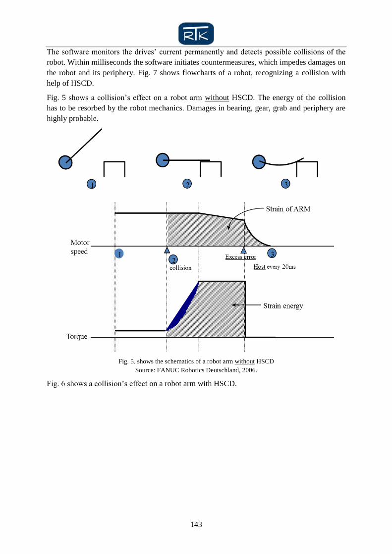
The software monitors the drives’ current permanently and detects possible collisions of the
robot. Within milliseconds the software initiates countermeasures, which impedes damages on
the robot and its periphery. Fig. 7 shows flowcharts of a robot, recognizing a collision with
help of HSCD.
Fig. 5 shows a collision’s effect on a robot arm without HSCD. The energy of the collision
has to be resorbed by the robot mechanics. Damages in bearing, gear, grab and periphery are
highly probable.
Fig. 5. shows the schematics of a robot arm without HSCD
Source: FANUC Robotics Deutschland, 2006.
Fig. 6 shows a collision’s effect on a robot arm with HSCD.

144
Fig. 6. Flowchart collision detection HSCD,
Source: FANUC Robotics Deutschland, Technical Presentations, 2006
In the moment of a collision the control recognizes an increase of moment and drive current
Fig. 7. The affected drives will be changed with maximum torque to the opposite direction
immediately. A great deal of the kinetic energy is resorbed by the drives which protects
expensive grabs or parts of damages.
Fig. 7. shows the schematics of a robot arm with HSCD
Source: FANUC Robotics Deutschland, Technical Presentations, 2006

145
Software tools also make robots faster and more precise. Several manufacturers offer
programs that optimize braking and acceleration curves of the different robot axes, which
allow faster movements. Other programs consider production tolerances and improve the
mathematic model of the robots kinematics. Thus, the robot is able to move on very precise
paths. This feature is used mainly for robots in the field of remote laser welding.
The software tools are processed in the electronic components of the robot control. Memory,
clock frequency, interfaces and BUS compatibility influence their performance.
3. 4 SAFETY ROBOTS SYSTEMS OR “SAFE ROBOT”
Robots of the security classes 3 and 4 are so-called “safe robots“ that are allowed for
operation in a common room with human workers [19]. This issue has been gaining
importance since the robot density (number of robots) per manufacturing plant has increased
more and more.
There still are processes that cannot be fulfilled by robots economically or technically. This
leads to the situation that working areas have to be shared by robots and humans [19]. Most
industrial countries allow such interactions between human workers and robots only under
strict security standards. Respective installations have to be constructed in a two-channeled
way. Operators of such robots have to secure each robot axis with two-channel cam rails.
On the one hand this measure is very expensive; on the other hand the robot kinematic is
impeded by the large components (Fig. 8.)
Fig. 8 shows axis 1 and 2 of a robot that are secured in a two-channeled hardware way
Source: FANUC Robotics, Technical Presentations 2006, Hardware zone switch

146
Modern robots are equipped with so-called dual check safety systems. It includes software as
well as a hardware component and also ensures the required two channels.
Dual Check Safety (DCS) hardware uses redundant magnetic contactors, I/O-channels and
CPUs. Mutual data and result checking are done by Main-CPU and Communication-CPU,
very similar to the redundant systems in airplanes. Same external interface (E-Stop, fence,
servo/MCC) are maintained as with the controller hardware based system Fig.9.
Fig. 9. shows the flowchart of the Dual-Check-Safety-system.
Source: FANUC Robotics, Technical Presentations, Dual-Check Safety, 2009
The robot position and speed can be safely monitored and the robot can be safely stopped to
avoid hazards for operators and other persons Fig. 10.
Fig. 10. Safety Zone
Source: FANUC Robotics, Technical Presentations, Safety Zone, 2009
147
3. 5 MULTI AXIS SYSTEMS AND COOPERATING ROBOTS
Multi axis systems have been reduced to 16 axes for a long time. This means that robots with
6 robot axes and 10 external axes were sufficient to realize most industrial applications [2].
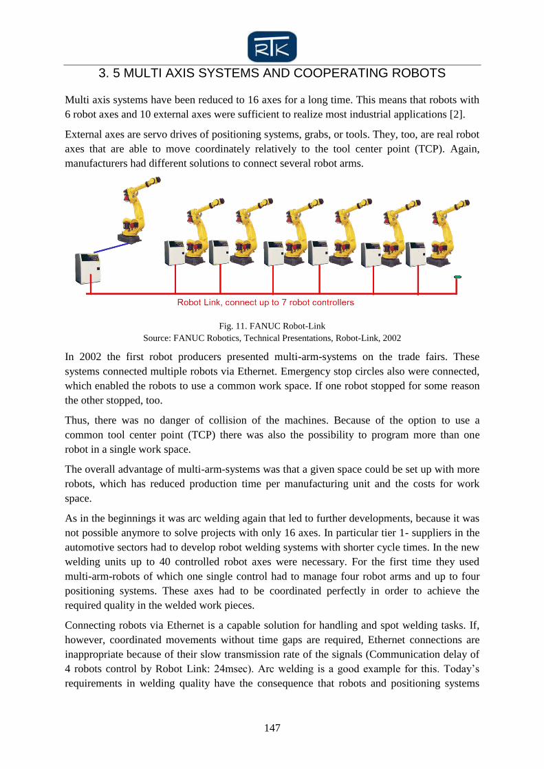
External axes are servo drives of positioning systems, grabs, or tools. They, too, are real robot
axes that are able to move coordinately relatively to the tool center point (TCP). Again,
manufacturers had different solutions to connect several robot arms.
Fig. 11. FANUC Robot-Link
Source: FANUC Robotics, Technical Presentations, Robot-Link, 2002
In 2002 the first robot producers presented multi-arm-systems on the trade fairs. These
systems connected multiple robots via Ethernet. Emergency stop circles also were connected,
which enabled the robots to use a common work space. If one robot stopped for some reason
the other stopped, too.
Thus, there was no danger of collision of the machines. Because of the option to use a
common tool center point (TCP) there was also the possibility to program more than one
robot in a single work space.
The overall advantage of multi-arm-systems was that a given space could be set up with more
robots, which has reduced production time per manufacturing unit and the costs for work
space.
As in the beginnings it was arc welding again that led to further developments, because it was
not possible anymore to solve projects with only 16 axes. In particular tier 1- suppliers in the
automotive sectors had to develop robot welding systems with shorter cycle times. In the new
welding units up to 40 controlled robot axes were necessary. For the first time they used
multi-arm-robots of which one single control had to manage four robot arms and up to four
positioning systems. These axes had to be coordinated perfectly in order to achieve the
required quality in the welded work pieces.
Connecting robots via Ethernet is a capable solution for handling and spot welding tasks. If,
however, coordinated movements without time gaps are required, Ethernet connections are
inappropriate because of their slow transmission rate of the signals (Communication delay of
4 robots control by Robot Link: 24msec). Arc welding is a good example for this. Today’s
requirements in welding quality have the consequence that robots and positioning systems
148
have to move simultaneously and in a coordinated way. These technical requirements can
only be fulfilled by multi-arm-robots who manage their whole movement with one CPU.
Complex welding units as they are often used by automotive suppliers can have up to 40
servo axes. The robot control, consequently, has to address these 40 axes without any time
delay. The controls are organized in a way that there is one main CPU and four additional side
controller-cabinets in which the power modules of the axes are installed.
For several years arc welding was the only application that required multi-arm-robot-systems
with more than 16 axes. This situation changed when robotics found their way into the
picking market.
Picking is the handling of mass production work pieces that leave the machines in huge
numbers on conveyor belts and have to be sorted, arranged or packed by robots. Robot arms
stand beside or hang above these conveyor belts and have the task to manipulate the products
in a given way at very fast speed. Working areas of the single robots overlap and there is the
necessity that the work pieces have to be assigned to certain robot arms. These circumstances
are the reason for using multi-arm-technology in this field of application.
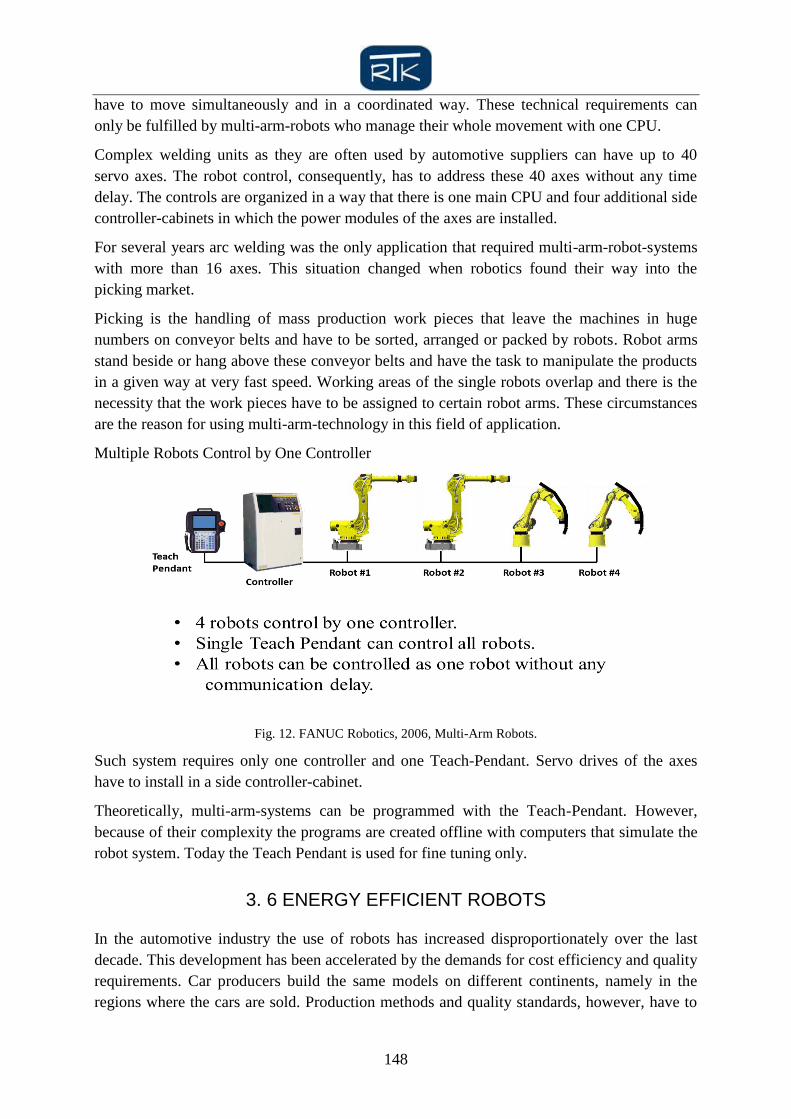
Multiple Robots Control by One Controller
Fig. 12. FANUC Robotics, 2006, Multi-Arm Robots.
Such system requires only one controller and one Teach-Pendant. Servo drives of the axes
have to install in a side controller-cabinet.
Theoretically, multi-arm-systems can be programmed with the Teach-Pendant. However,
because of their complexity the programs are created offline with computers that simulate the
robot system. Today the Teach Pendant is used for fine tuning only.
3. 6 ENERGY EFFICIENT ROBOTS
In the automotive industry the use of robots has increased disproportionately over the last
decade. This development has been accelerated by the demands for cost efficiency and quality
requirements. Car producers build the same models on different continents, namely in the
regions where the cars are sold. Production methods and quality standards, however, have to
149
be the same on each continent.
In the past producing a new car model required 500 to 1,000 robots for one project –
depending on the production quantities of cars. Spot welding at the car body was the main
application.
Today several car-types produced on one production line and the manufacturers have global
production strategies. This led to the situation that robot applications are much more wide-
spread today. Spot welding is still the most common task, but robots are as well used for
transport, assembling, measuring, painting, loading and much more duties. In such projects up
to 5,000 robots are needed.
Consequently, larger Car plants can reach robot populations of several 10,000 machines.
These numbers are responsible for an increase in energy consumption, which makes this
aspect an important cost factor [20].
Basically, energy consumption of robots is influenced by the number and use of their drives.
This depends on the size of moved work pieces as well as their acceleration. Technical
considerations like the size of drives and amplifiers or intelligent stand-by features are
secondary. Thus, the operator has the biggest influence on the robots energy consumption.
Choosing the right robots related primarily to the load the machine has to carry. A correctly
dimensioned robot is the basis for its efficient use. Even more important for an acceptable
consumption of energy is the way how robot movements are programmed.
Every car driver knows that too much acceleration and intense breaking between two traffic
lights leads to an increased mileage. Programming robots works in a similar way. The
stronger the machine has to work against physical mass inertia; the higher will be its energy
consumption.
Robot manufacturers react to these requirements by technical optimizations in mechanics,
drives and amplifiers, electronics, and software. Lightweight construction is one of the
keywords for this machine generation [7] [8].
Smaller and lighter robots not only reduce energy consumption, but also higher process
speeds as well as reduced space requirements. Controls are equipped with smaller amplifiers
that have less current drain and do not need the same cooling as larger amplifiers. Braking
energy is recuperation and can be used again by the network.
The Energy-Flow-Analysis in Fig. 13 from K. Wagner, shows how large the part of energy
demand only for the robot motion is. The basic of this analysis is the robot model FANUC
R2000- series, payload 165-250Kg. This is worldwide the most used robot-class. 73,1% of the
whole electrical energy is used for the robot-drives-units. This percentage distribution
indicates very clear the optimization potential.

150
Fig. 13. Wagner, Klaus; 2011; Fanuc Robotics; Energy flow analysis, Robot R2000 series.
The biggest potential of energy consumption, the robot’s kinetic energy, is dealt with by
developing innovative offline programming and simulation software. These software tools are
able to improve existing robot programs under consideration of energy aspects by having the
robot’s kinetic energy as close to the constant level as possible..
This method helps optimizing energy consumption for existing robot systems as well as
systems that yet have to be programmed. How powerful this simulation-software is, shows an
analysis of an optimizing-loop on a ROBOGUIDE station Fig. 13.
Fig. 14 Wagner, Klaus; 2011; Fanuc Robotics; Energy-Optimizing with ROBOGUIDE
Motion-optimizing reduces the energy consumption by 8,3 % versus the original motion-
program. Cycle time remains unchanged.

151
IV. CONCLUSIONS
If you had to name a megatrend that has influenced the development of robot technology the
last two decades and will keep influencing it in the future, it clearly has to be the issue of
software tools. As mentioned in the introduction computer producer APPLE and their easy
programmable APPS have shown that the world of software is as eternal as for instance the
literary world.
Every programmer is able to create something completely new and to extend the features of
computers, smartphones, and machines. If status quo of computer hardware stayed like it is
today and developments were restricted to software, most people would not notice a
slowdown of the overall development. Software unites competences and experiences of robot
users and developers. To build the infrastructure for software developers is possible at any
place of the world [18].
Even today software is a decisive factor in technological advancements. It calculates and
compensates the deflection of robot arms under heavy loads and at high speeds software
eliminates vibrations and resonance.
Also the communication management is controlled by software as robot security is almost
completely based on software models that monitor virtual safety rooms and evaluates the
situation by matching the redundancies of two processors. In the field of multi axis systems
and cooperating robots, software is the foundation for common planning of movement paths.
Beside CPU power on the hardware side this is an important technological part.
The advancements in energy efficiency of robots, too, are dominated by software tools. The
development of economical drives and lighter materials is a long process that takes several
years until noticeable results improve the efficiency. But intelligent software can optimize
robot programs immediately and, thus, realize large energy saving potentials [Fig. 14].
The model of APPS has not reached the industry yet. Many industrial companies cannot
imagine that software is open to third party users and those external programmers and
software developers create programs without their own influence. The immense potential of
development resources that already exists will enter the industry as well. Some robot
manufactures have been working on this topic actively since 2010.
However, the unquestionably exposed status of software is not supposed to curtail the worth
of controls and sensor systems. The simplified view that describes the control as the brain, the
software as the intelligence, and the sensors as the senses of a robot, will help to evaluate the
importance of each of the three factors. It is easy to recognize that robot control, sensor
system and software are equally important.
The main differences between the three fields of technology are speed of development,
necessary investment volumes, and potentials of resources. Controls will be developed at the
pace that is valid for machine tools and computer technology. A separate development of
robot controls cannot be expected.
The outlook for sensor systems is much more difficult. In particular the sector of vision
sensors is connected to the developments in photography and camera technology. Speaking of
152
consumer electronics advancements in these sectors are much faster than in the industry.
Thus, advancements in sensor systems will not develop evenly. While vision sensors will take
the speed of consumer electronics, touch sensors, force sensors, and measuring sensors will
keep the momentary speed of its industrial environment.
BIBLIOGRAPHY
[1] SNYDER, W.: Computergesteuerte Industrieroboter. Grundlagen und Einsatz. VCH Weinheim, 1990,
ISBN- 3 527 26630 5
[2] ZIVANOVIC; VUKOBRATOVIC, Multi-Arm Cooperating Robots: Dynamics and Control (Intelligent
Systems, Control and Automation: Science and Engineering), Springer 12/2005 ISBN-10: 140204268X
[3] SPUR, G. (Hrsg): Industrieroboter: Steuerung, Programmierung und Daten“, Hanser, Munich 1979 (ISBN
3-446-12686-4)
[4] CRAIG, John, 2005, Introduction to Robotics - Mechanics and Control. New York: Pearson Prentice Hall,
ISBN-10: 0201543613.
[5] VDI-Nachrichten 4/1999 „Die erste PC-basierte Robotersteuerung stellte Kuka selber bereits 1996 vor“.
www.vdi-nachrichten.com/artikel/Ein-Netz-fuer-alle-Anwendungen/795/2
[6] AUTOMATION 1/2012 “Klein wie ein Blatt Papier“
www.automationnet.de/index.cfm?pid=1440&pk=114558
[7] VDI-Nachrichten 5/2010 “Automatisierungstechnik im Dienst des Klimaschutzes“ www.vdi-
nachrichten.com/artikel/Automatisierungstechnik-im-Dienst-des-Klimaschutzes/47915/2
[8] VDI-Nachrichten 9/2011 “Wir brauchen auch im Leichtbau Leuchtturmprojekte“ www.vdi-
nachrichten.com/artikel/Wir-brauchen-auch-im-Leichtbau-Leuchtturmprojekte/54799/1
[9] MASCHINENMARKT 9/2006 „Die Leichtigkeit des Seins”
www.maschinenmarkt.vogel.de/themenkanaele/automatisierung/robotik/articles/3167/
[10] MASCHINENMARKT 9/2006 “Schwere Jungs”, Rüdiger Kroh
www.maschinenmarkt.vogel.de/themenkanaele/automatisierung/robotik/articles/2970/
[11] DER SPIEGEL 21/2007; “Kraftprotz aus der Provinz“; Thadeusz, Frank
http://www.spiegel.de/spiegel/print/d-51644732.html
[12] MASCHINENMARKT 4/2009 , Rüdiger Kroh “Fanuc-Robotics-Chef rechnet mit Ausweitung der
Traglasten nach oben und unten“
www.maschinenmarkt.vogel.de/themenkanaele/automatisierung/robotik/articles/182387/
[13] HESSE; Monkmann; Steinmann; Schunk ROBOTERGREIFR, Hansa Verlag, ISBN 3-446-22920-5
[14] RUOKANGAS, C.C: Black; Martin; Schönwald; INTEGRATION OF MULTIBLE SENSORS TO
PROVIDE FLEXIBLE CONTROL STRATEGIES, CH 2282-2/86/0000/1947$01.00,IEE, 1986
[15] ELEKTROTECHNIK 1/2012, “Ethernet-I/O-Module“, 25.01.2012, Ines Näther
www.elektrotechnik.vogel.de/feldkommunikation/articles/346129/
[16] VDI-Nachrichten 4/2000, “Roboter montiert mit geübter Hand“ www.vdi-nachrichten.com/artikel/Roboter-
montiert-mit-geuebter-Hand/2657/2
[17] VDI-Nachrichten 5/2008, “Künstliche Augen, Ohren, Nasen und mehr“ www.vdi-
nachrichten.com/artikel/Kuenstliche-Augen-Ohren-Nasen-und-mehr/38492/1
[18] VDI-Nachrichten 10/2011, H. Weiss www.vdi-nachrichten.com/artikel/Sehnsuechtiges-Warten-auf-
serienreife-Service-Roboter/55258/2
[19] VDI- Nachrichten 5/2003, B. ODR/IPA/KÄM “Japaner mögen Bi-Ped-Robots - Mensch-Roboter-
Interaktion” www.vdi-nachrichten.com/artikel/Japaner-moegen-Bi-Ped-Robots/11936/2
[20] PRODUKTION No. 19/2009, Annika Mentgen
www.produktion.de/imperia/md/content/ai/produktion/fachartikel/2009/19/pro09_19_014.pd
[21] FANUC Robotics Maintenance Handbook, S-420 Controller with Side-Cabinet, 1990 www.fanuc.co.jp
[22] FANUC Robotics Maintenance Handbook, Controller R-30iA, 2010 www.fanuc.co.jp.