prince wafer check technical data sizes 2-48 inch · prince wafer check technical data sizes 2-48...
TRANSCRIPT
Wafer Check Valves
0Tyco reserves the right to change product design and specifications KVUDD-0033-EN-0102without notice. Copyright © 2000 by Tyco International Ltd.
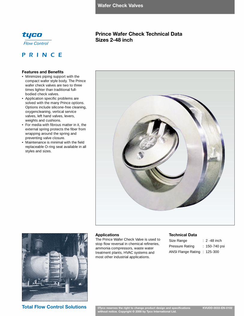
Prince Wafer Check Technical DataSizes 2-48 inch
Features and Benefits• Minimizes piping support with the
compact wafer style body. The Princewafer check valves are two to threetimes lighter than traditional full-bodied check valves.
• Application specific problems aresolved with the many Prince options.Options include silicone-free cleaning,oxygencleaning, vertical servicevalves, left hand valves, levers,weights and cushions.
• For media with fibrous matter in it, theexternal spring protects the fiber fromwrapping around the spring andpreventing valve closure.
• Maintenance is minimal with the fieldreplaceable O-ring seat available in allstyles and sizes.
ApplicationsThe Prince Wafer Check Valve is used tostop flow reversal in chemical refineries,ammonia compressors, waste watertreatment plants, HVAC systems andmost other industrial applications.
Technical DataSize Range : 2 -48 inch
Pressure Rating : 150-740 psi
ANSI Flange Rating : 125-300
Total Flow Control Solutions

Wafer Check Valves
Tyco reserves the right to change product design and specifications 2without notice. Copyright © 2000 by Tyco International Ltd.
Product Summary
ANSI Pressure
Flange Rating Size Body Bushing/ Plug or Outside
Series Rating (psi) (in.) Material Disc/Arm Bearing Seat Spring Shaft Seal Hardware
Figure 809 300 740 2”–12” Carbon Steel 316 SS N/A TFE 316 SS (Std.) Carbon Steel N/AInconel 750
Figure 810 125 150 2”–12” Cast Iron 316 SS N/A BUNA-N (Std.) 316 SS (Std.) Carbon Steel N/AEPDM 2–5 inch
Fluoroelastomer 17-7 PH SS (Std.)TFE 6–12 inch
Metal-to-metal Inconel 750150 285 2”–12” Carbon Steel 316 SS N/A BUNA -N (Std.) 316 SS (Std.) Carbon Steel N/A
316 SS EPDM 2–5 inchFluoroelastomer 17-7 PH SS (Std.)
TFE 6–12 inchMetal-to-metal Inconel 750
Figure 813 125 150 2”–12” Cast Iron 316 SS Bronze BUNA-N (Std.) 316 SS (Std.) BUNA-N (Std.) • 2 Pos AdjustableEPDM Inconel 750 EPDM Spring (Std.)
Fluoroelastomer Fluoroelastomer • LeverTFE • Adjustable Weight
Metal-to-metal150 285 2”–12” Carbon Steel 316 SS Bronze BUNA-N (Std.) 316 SS (Std.) BUNA-N (Std.) • 2 Pos Adjustable
316 SS 316 SS EPDM Inconel 750 EPDM Spring (Std.)Fluoroelastomer Fluoroelastomer • Lever
TFE • Adjustable WeightMetal-to-metal
Figure 815 125 150 12”–36” Cast Iron 316 SS Bronze BUNA-N (Std.) Carbon St. (Std) N/A • Adjustable SpringEPDM 316 SS • Lever
Fluoroelastomer • Adjustable Wt (Std.)Ni-AB • Hydraulic Cushion
316 SS • Limit Switch
150 230 12”–20” Carbon Steel 316 SS Bronze BUNA-N (Std.) Carbon St. (Std.) N/A • Adjustable Spring316 SS EPDM 316 SS • Lever
Fluoroelastomer • Adjustable Wt.(Std.)Ni-AB • Hydraulic Cushion
316 SS • Limit Switch150 150 24”–48” Carbon Steel 316 SS Bronze BUNA-N (Std.) Carbon St. (Std.) N/A • Adjustable Spring
316 SS EPDM 316 SS • LeverFluoroelastomer • Adjustable Wt.(Std.)
Ni-AB • Hydraulic Cushion• Limit Switch
Notes
1. Left hand versions available on allexternal spring models for horizontalservice.
2. Not for use in pulsating or reciprocatingservices.

Wafer Check ValvesCheck Valve Selection Diagram
Tyco reserves the right to change product design and specifications 3without notice. Copyright © 2000 by Tyco International Ltd.
Gather Service Condition Information• Media • Line Size• Temperature, Pressure • Maximum ∆P• Flow, Cv’s • Physical Valve Parameters
Prioritize and Evaluate Service Condition Information
Select Body Material based on Pressure Conditions and Fluid Compatability
Select Appropriate External Spring Material
Select Appropriate External Spring Valve withLever, Weight, Cushion and Limit Switches
Select Appropriate External Spring Valve with Lever
Select Valve Style Internal vs. External Spring
Based on Service Conditions
Select Appropriate Seat Materialbased on Fluid Compatability
No
Yes
No
No
Yes
No
Yes
No
No
Yes
Yes
Internal
External
Is Valve Body Pressure Rating withinANSI Class 125/150
or 300?
Will ServiceTemperature Conditions be within Seat Material
Limitations?
Is a Lever and Weight
Required?
Is Cushioning Required?
Are LimitSwitches Required?
Is a Lever Required?
START
A
Select Appropriate Internal Spring Material
Select Appropriate Internal Spring Valve
Select Appropriate External Spring Valve withLever, Weight and Limit Switches
Select AppropriateExternal SpringValve with Lever
and Weight
Select Appropriate External Spring Valve withLever, Weight and Cushion
Select Appropriate External Spring Valve
Select Appropriate External Spring Valve
Consult Factory
Yes
No
No
Yes
Is Alternate sat MaterialAvailable?
Are Limit SwitchesRequired?
Consult Factory
Yes
Wafer Check ValvesFlow Characteristics
Tyco reserves the right to change product design and specifications 4without notice. Copyright © 2000 by Tyco International Ltd.
1008060
40
20
108.06.0
4.0
2.0
1.00.80.6
0.4
0.2
0.1
10 20 40 60 80 100
200
400
600
800
1,00
0
2,00
0
4,00
0
6,00
08,
000
10,0
00
20,0
00
40,0
00
60,0
0080
,000
100,
000
200,
000
400,
000
600,
000
800,
000
1,00
0,00
0
2”
2 /
”1 2 3” 4” 5” 6” 8” 10”
12”
14”
16”
18”
20”
24”
30”
36”
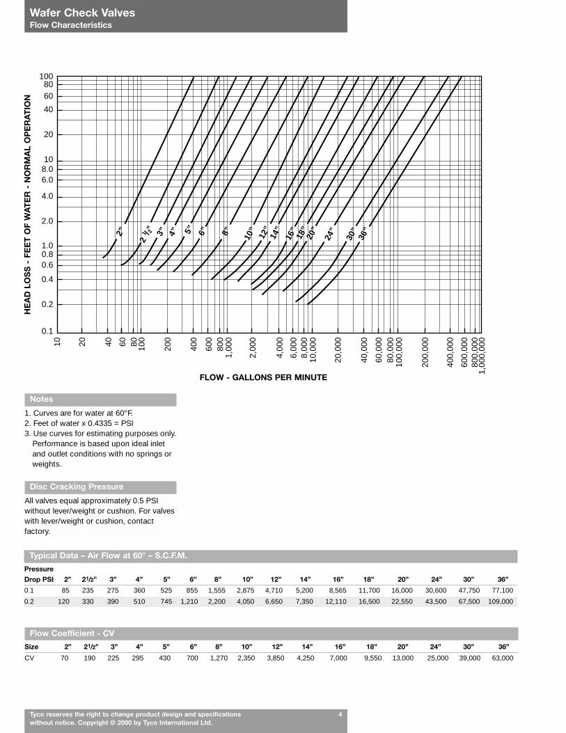
Typical Data – Air Flow at 60° – S.C.F.M.
Pressure
Drop PSI 2” 21/2” 3” 4” 5” 6” 8” 10” 12” 14” 16” 18” 20” 24” 30” 36”
0.1 85 235 275 360 525 855 1,555 2,875 4,710 5,200 8,565 11,700 16,000 30,600 47,750 77,100
0.2 120 330 390 510 745 1,210 2,200 4,050 6,650 7,350 12,110 16,500 22,550 43,500 67,500 109,000
Flow Coefficient - CV
Size 2” 21/2” 3” 4” 5” 6” 8” 10” 12” 14” 16” 18” 20” 24” 30” 36”
CV 70 190 225 295 430 700 1,270 2,350 3,850 4,250 7,000 9,550 13,000 25,000 39,000 63,000
Disc Cracking Pressure
All valves equal approximately 0.5 PSIwithout lever/weight or cushion. For valveswith lever/weight or cushion, contactfactory.
FLOW - GALLONS PER MINUTE
HE
AD
LO
SS
- F
EE
T O
F W
AT
ER
- N
OR
MA
L O
PE
RA
TIO
N
Notes
1. Curves are for water at 60°F.2. Feet of water x 0.4335 = PSI3. Use curves for estimating purposes only.
Performance is based upon ideal inletand outlet conditions with no springs orweights.
Tyco reserves the right to change product design and specifications 5without notice. Copyright © 2000 by Tyco International Ltd.
Wafer Check ValvesTechnical Information
For Gases
Pressure Drop = S.G.
Where:QV = Flow in standard cubic
feet per minuteP1 = Upstream pressure absolute
(psi + 14.7)G = Specific Gravity of GasT = Temperature (Rankine)
(°F + 460°)CV = Valve flow coefficient from table
Note: 120 fps is the nominal maximumvelocity for gases.
For Liquids
Pressure Drop = S.G.
Where:QL = Flow in gallons per minuteS.G. = Specific Gravity of LiquidCV = Valve flow coefficient from table
Note: 30 fps is the nominal maximumallowable velocity for liquids.
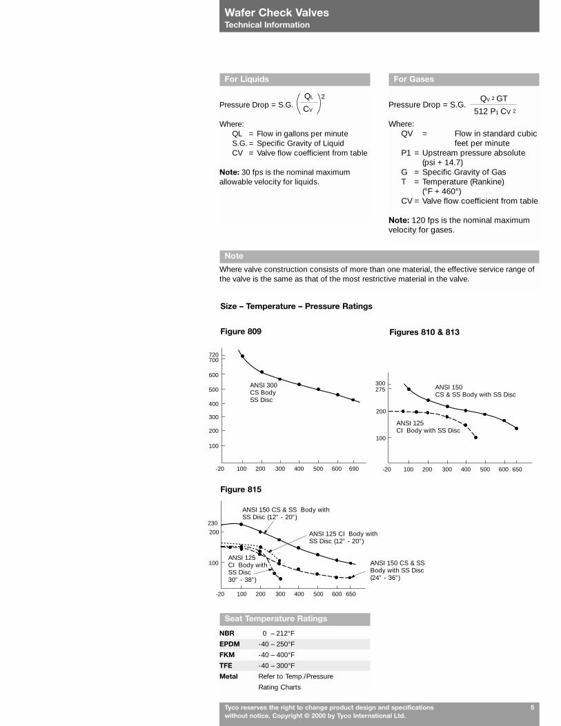
Size – Temperature – Pressure Ratings
QL 2
CV
QV 2 GT
512 P1 CV 2
Note
Where valve construction consists of more than one material, the effective service range ofthe valve is the same as that of the most restrictive material in the valve.
Seat Temperature Ratings
NBR 0 – 212°F
EPDM -40 – 250°F
FKM -40 – 400°F
TFE -40 – 300°F
Metal Refer to Temp./Pressure
Rating Charts
100
200
300
400
500
600
700720
-20 100 200 400300 500 600 690
100
200
-20 100 200 400300 500 600 650
275300
100
200
230
-20 100 200 400300 500 600 650
Figure 809 Figures 810 & 813
Figure 815
ANSI 300CS BodySS Disc
ANSI 150CS & SS Body with SS Disc
ANSI 125CI Body with SS Disc
ANSI 125 CI Body with SS Disc (12” - 20”)
ANSI 150 CS & SS Body with SS Disc (12” - 20”)
ANSI 150 CS & SS Body with SS Disc (24” - 36”)
ANSI 125 CI Body with SS Disc 30” - 38”)
Wafer Check Valves
Tyco reserves the right to change product design and specifications 6without notice. Copyright © 2000 by Tyco International Ltd.
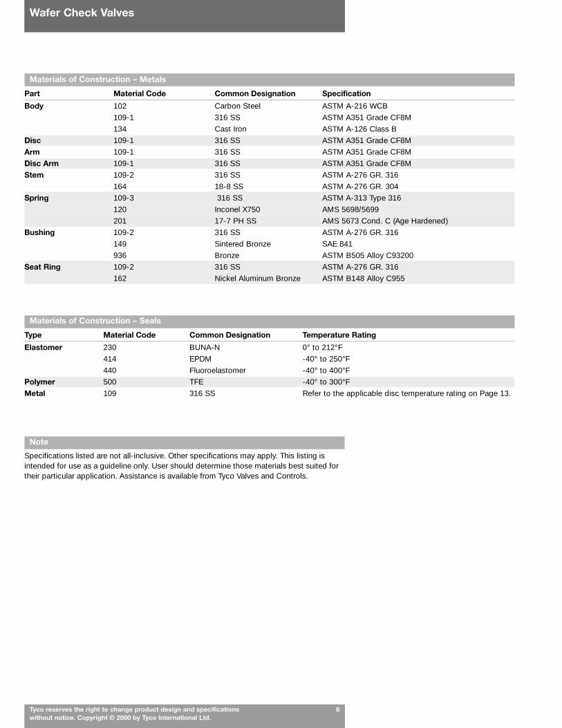
Materials of Construction – Metals
Part Material Code Common Designation Specification
Body 102 Carbon Steel ASTM A-216 WCB
109-1 316 SS ASTM A351 Grade CF8M
134 Cast Iron ASTM A-126 Class B
Disc 109-1 316 SS ASTM A351 Grade CF8M
Arm 109-1 316 SS ASTM A351 Grade CF8M
Disc Arm 109-1 316 SS ASTM A351 Grade CF8M
Stem 109-2 316 SS ASTM A-276 GR. 316
164 18-8 SS ASTM A-276 GR. 304
Spring 109-3 316 SS ASTM A-313 Type 316
120 Inconel X750 AMS 5698/5699
201 17-7 PH SS AMS 5673 Cond. C (Age Hardened)
Bushing 109-2 316 SS ASTM A-276 GR. 316
149 Sintered Bronze SAE 841
936 Bronze ASTM B505 Alloy C93200
Seat Ring 109-2 316 SS ASTM A-276 GR. 316
162 Nickel Aluminum Bronze ASTM B148 Alloy C955
Materials of Construction – Seals
Type Material Code Common Designation Temperature Rating
Elastomer 230 BUNA-N 0° to 212°F
414 EPDM -40° to 250°F
440 Fluoroelastomer -40° to 400°F
Polymer 500 TFE -40° to 300°F
Metal 109 316 SS Refer to the applicable disc temperature rating on Page 13.
Note
Specifications listed are not all-inclusive. Other specifications may apply. This listing isintended for use as a guideline only. User should determine those materials best suited fortheir particular application. Assistance is available from Tyco Valves and Controls.

Wafer Check ValvesInstallation Information
Tyco reserves the right to change product design and specifications 7without notice. Copyright © 2000 by Tyco International Ltd.
Flange and Bolting Data – Figures 810, 813, and 815
ANSI CLASS 125/150Size Diameter of No. of Bolt(in.) Bolt Circle Bolts Thread
2 4 3/4 4 5/8 – 1121/2 5 1/2 4 5/8 – 113 6 4 5/8 – 114 7 1/2 8 5/8 – 115 8 1/2 8 3/4 – 106 9 1/2 8 3/4 – 108 11 3/4 8 3/4 – 10
10 14 1/4 12 7/8 – 912 17 12 7/8 – 914 18 3/4 12 1 – 816 21 1/4 16 1 – 818 22 3/4 16 11/8 – 720 25 20 1 1/8 – 724 29 1/2 20 1 1/4 – 730* 36 28 1 1/4 – 736* 42 3/4 32 1 1/2 – 6
* ANSI Class 125 Only
Flange and Bolting Data – Figure 809
ANSI CLASS 300Size Diameter of No. of Bolt(in.) Bolt Circle Bolts Thread
2 5 8 5/8-113 6 5/8 8 3/4 – 104 7 7/8 8 3/4 – 105 9 1/4 8 3/4 – 106 10 5/8 12 3/4 – 108 13 12 7/8-910 15 16 1-812 18 16 1 1/8-7
Recommendations for Installation Position
1. Position the check valve to promote smooth flow.2. Allow clearance for disc movement.3. Install the valve in horizontal or upward flow for proper valve closure.
Caution: Do not use with reciprocating compressors, or in other pulsating services.
Note HingePosition
Normal Flow
Normal Flow
Normal Flow
Normal Flow
Note HingePosition
CORRECT POSITION INCORRECT POSITION
Wafer Check ValvesPhysical Dimensions
Tyco reserves the right to change product design and specifications 8without notice. Copyright © 2000 by Tyco International Ltd.
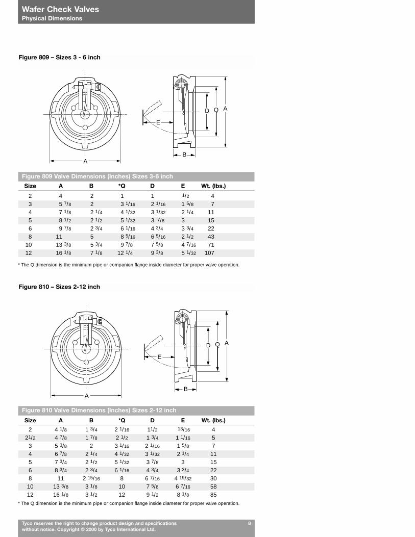
Figure 809 Valve Dimensions (Inches) Sizes 3-6 inch
Size A B *Q D E Wt. (lbs.)
2 4 2 1 1 1/2 43 5 7/8 2 3 1/16 2 1/16 1 5/8 74 7 1/8 2 1/4 4 1/32 3 1/32 2 1/4 115 8 1/2 2 1/2 5 1/32 3 7/8 3 156 9 7/8 2 3/4 6 1/16 4 3/4 3 3/4 228 11 5 8 5/16 6 5/16 2 1/2 43
10 13 3/8 5 3/4 9 7/8 7 5/8 4 7/16 7112 16 1/8 7 1/8 12 1/4 9 3/8 5 1/32 107
* The Q dimension is the minimum pipe or companion flange inside diameter for proper valve operation.
Figure 810 Valve Dimensions (Inches) Sizes 2-12 inch
Size A B *Q D E Wt. (lbs.)
2 4 1/8 1 3/4 2 1/16 11/2 13/16 421/2 4 7/8 1 7/8 2 1/2 1 3/4 1 1/16 5
3 5 3/8 2 3 1/16 2 1/16 1 5/8 74 6 7/8 2 1/4 4 1/32 3 1/32 2 1/4 115 7 3/4 2 1/2 5 1/32 3 7/8 3 156 8 3/4 2 3/4 6 1/16 4 3/4 3 3/4 228 11 2 15/16 8 6 7/16 4 19/32 3010 13 3/8 3 1/8 10 7 5/8 6 7/16 5812 16 1/8 3 1/2 12 9 1/2 8 1/8 85
* The Q dimension is the minimum pipe or companion flange inside diameter for proper valve operation.
A
E
D Q A
B
A
E
D Q A
B
Figure 810 – Sizes 2-12 inch
Figure 809 – Sizes 3 - 6 inch

Wafer Check ValvesPhysical Dimensions
Tyco reserves the right to change product design and specifications 9without notice. Copyright © 2000 by Tyco International Ltd.
Figure 813 Valve Dimensions (Inches) Sizes 2-12 inch
Size A B *Q D E F G H J K Wt. (lbs.)
2 4 1/8 1 3/4 2 1/16 1 1/2 13/16 3 1/16 4 23/32 6 1/2 5 5/32 2 21/32 52 1/2 4 7/8 1 7/8 2 15/32 1 3/4 1 1/16 3 5/16 5 7/32 7 1/2 5 7/8 3 3/32 6
3 5 3/8 2 3 1/16 2 1/16 1 5/8 3 15/16 5 11/16 8 1/2 6 13/16 3 5/8 94 6 7/8 2 1/4 4 1/32 3 1/32 2 1/4 3 15/16 6 13/32 8 1/2 6 3/4 3 13/32 135 7 3/4 2 1/2 5 1/32 3 7/8 3 5 15/32 7 7/32 8 3/8 6 19/32 3 1/2 196 8 3/4 2 3/4 6 1/16 4 3/4 3 25/32 5 29/32 7 3/4 8 3/8 6 21/32 3 1/4 248 11 2 15/16 7 31/32 6 7/16 4 5/8 6 31/32 9 5/32 9 3/8 7 7/16 3 5/8 3210 13 3/8 3 1/8 10 7 5/8 6 7/16 5 1/2 10 13/32 10 3/8 8 1/16 4 3/16 6012 16 1/8 3 1/2 12 9 1/2 8 1/8 6 7/16 12 7/32 12 9 3/8 4 11/16 87
* The Q dimension is the minimum pipe or companion flange inside diameter for proper valve operation.
Figure 815 Valve Dimensions (Inches) Sizes 12-48 inch
Size A B *Q D E F G H J K L M Wt. (lbs.)
12 16 1/8 4 3/4 12 9 1/2 7 7/8 17 9 17 17 4 7/8 – 9 9 212 14 17 5/8 7 3/4 13 1/4 10 3/16 7 30 13 31/64 21 18 3/4 3 1 – 8 7 35016 20 8 3/4 15 1/4 11 8 30 12 61/64 23 21 1/4 4 1 – 8 8 41018 21 1/2 8 3/4 17 1/4 12 1/2 10 30 12 61/64 24 22 3/4 3 1 1/8 – 7 10 45020 23 3/4 9 3/4 19 1/4 15 12 31 13 1/32 28 25 5 1 1/8 – 7 12 77524 28 1/4 9 3/4 23 1/4 18 1/2 15 31 13 1/32 32 29 1/2 6 1 1/4 – 7 15 92530 34 1/4 9 3/4 29 1/4 23 1/2 22 31 13 1/32 38 36 7 1 1/4 – 7 23 122536 41 1/8 14 1/2 35 28 19 3/8 32 13 1/8 44 42 3/4 8 1 1/2 – 6 18 13/16 210042 47 7/8 17 41 33 22 36 15 3/8 47 1/4 49 1/2 8 1 1/2 – 6 18 13/16 359048 54 3/8 20 5/8 47 37 1/2 24 1/4 42 16 1/4 50 3/4 56 10 1 1/2 – 6 18 13/16 4850
* The Q dimension is the minimum pipe or companion flange inside diameter for proper valve operation.
A
G
F
H
J K
PRINCE E
D Q A
B
Figure 813 (with Optional Lever & Weight) Sizes 2-12 inch
Figure 815 (with Optional Cushion) Sizes 12-48 inch
Open
Port
FM
Q D
B E
AG
KL
H

Wafer Check ValvesApplications
Tyco reserves the right to change product design and specifications 10without notice. Copyright © 2000 by Tyco International Ltd.
2
6
6
11
4
5 5 5
7
3
444
Diagram Key
1. Fractionating column2. Coolers3. Distillate drum4. Distillate reflux and product pumps5. Sour water pumps6. Quench oil pumps7. Quench oil rundown cooler8. Fuel oil stripping pumps
Diagram Key
1. Caustic scrubber2. Caustic surge tank3. Three-stage gas compressor4. Aftercollers5. Separators6. Caustic pumps7. Distillate stripper
2
1
76
8
34
5
6
Chemical – Fractionating Column
Petrochemical – Compressor and Light End Fractionating Section
Legend
= Prince Check Valve
= Block Valve
= Control Valve
Legend
= Prince Check Valve
= Block Valve
= Control Valve
Distillate
Make-up oil
Fuel oil
Steam
Steam
Distillate
Gas
Feed water
Caustic
Depropanizerchiller
To DistillateReservoir
ToBenzene Cracker
Quench oil
From cracking furnaceand heat exchangers

Wafer Check ValvesApplications
Tyco reserves the right to change product design and specifications 11without notice. Copyright © 2000 by Tyco International Ltd.
Diagram Key
1. Continuous digester2. Heat exchanger - calorisator3. Heat exchanger4. Condensate vessel5. Flash tanks
Diagram Key
1. Boilers2. Pumps3. Expansion tank4. Fan coil units
Legend
= Prince Check Valve
= Block Valve
= Control Valve
Legend
= Prince Check Valve
= Block Valve
= Control Valve
SteamCondensate
Chip Feed
3
1
2 2 2
45
5
44
44
2 2 2
1 1 1
2 2 2
3
Pulp and Paper – Continuous Digester
HVAC – Three Boiler Water Heating System
Presteamer
Whiteliquor
Blackliquor
Chipfeeder
Liquors
Switching valves
To presteamer
Continuous blow down system
Cold water supply

Wafer Check ValvesMaterial selection guide
Tyco reserves the right to change product design and specifications 12without notice. Copyright © 2000 by Tyco International Ltd.
Materials Selection Guide
Cast Carbon StainlessMaterial Iron Steel Steel BUNA-N EPDM Fluoroelastomer TFE
Acetaldehyde A A A C C B A
Acetic Acid, Air Free C C B C A C A
Acetone A A A C C C A
Acetylene A A A B A A A
Alcohols A A A A A B A
Aluminum Sulfate C C A A A A A
Ammonia A A A B B C A
Ammonium Nitrate C A A B A A A
Ammonium Sulfate C C A A A A A
Asphalt A A A C C B A
Beer B B A A A A B
Benzene A A A C C A A
Benzoic Acid C C A C C A A
Boric Acid C C A A A A A
Butane A A A B C B A
Calcium Chloride B B B A A A A
Carbolic Acid B B A C B A A
Carbon Dioxide, Dry A A A B A A A
Carbon Tetrachloride B B B C C A A
Citric Acid C D A A A A A
Coke Oven Gas A A A B C A A
Copper Sulfate C C B A A A A
Creosote A A A C C A A
Ether B B A C C B A
Ethyl Chloride C C A B A A A
Ethylene A A A B C B B
Ethylene Glycol A A A A A A B
Fatty Acids C C A B C A A
Ferric Chloride C C C C B A A
Ferrous Chloride C C C C B D A
Fluorocarbon Oil C C A D C C A
Formic Acid C C A C C C A
Freon 11 C C A B C C A
Freon 12 C C A A D C A
Freon 22 C C A C C C A
Fuel Oil C C A A C B A
Fruit Juices C B A B A A A
Gasoline B A A C C A A
Glucose D D A A A A A
Glycols A A A A A A A
Green Liquor C C A B B B A
Helium C B A A A B A
Hexane A A A B C A A
Hydrogen Gas B C A A A B A
Ink C C A B B A A
Isopropyl Alcohol A A A B A A A
Kerosene B A A A C A A
Ketones A A A C C C A
Lead Acetate C C B A A A A
Magnesium Hydroxide C A A A A A A
Mash C C A B A A A

Wafer Check ValvesMaterial selection guide
Tyco reserves the right to change product design and specifications 13without notice. Copyright © 2000 by Tyco International Ltd.
Materials Selection Guide (cont.)
Cast Carbon StainlessMaterial Iron Steel Steel BUNA-N EPDM Fluoroelastomer TFE
Mercury C A A A C D A
Methane (Gas) D B A A C D A
Mine Water (No Salts) C C A A A U D
Naptha B A A C C A A
Natural Gas (No H2S) B A A A A A A
Nitrogen Gas A A A A A A A
Oxygen Gas A A A B A A A
Ozone C B A C B A A
Paint Thinners C B A C C A A
Pentane A A A A C B A
Petrolatum A A A A C D A
Phosphorous C C A B C A A
Polystyrene Resins C C A C C D B
Potash C C A B A A A
Potassium Nitrate C A A A A A A
Propane (LPG) B B A A C D A
Pulp Stock C B A A A A A
Sea Water C C B A A A B
Sewage B B A A A B A
Sodium Acetate C B A B A A A
Sodium Chloride C C B A A A A
Sour Gas C B A C C A A
Steam C B A C C D B
Toluene A A A C C A A
Turpentine C B A C C A A
Vinyl Acetate C A A C D C B
Vinyl Chloride C C A C D D B
Water B B A B B A A
White Liquor C B A B B A A
Xylene C C A C C A A
Zinc Chloride C C A A A D A
Note
This information should be used as ageneral guide only.Many variables other than the chemicalresistance will influence the rate ofcorrosion and materials of construction.
Legend
A = Can be or is successfully being usedB = Proceed with cautionC = Should not be usedD = Information lacking

Wafer Check Valves
Tyco reserves the right to change product design and specifications 14without notice. Copyright © 2000 by Tyco International Ltd.
GeneralThe check valve shall be a wafer style(flangeless) swing check design utilizinga torsional spring to assist in fasterclosure. The valve must be capable ofgravity closure should the loss of springtension occur when system backpressure is present. Valves with discshinged in a line crossing the valvediameter, or with center posts, areunacceptable.
Body/SeatThe body shall be of the one-piececonstruction and shall possess amachined dovetail groove for a polymerseal. The seal shall not be vulcanized tofacilitate seat retention, and shall be fieldreplaceable. The seal shall providepositive shut-off at both low and highpressure.
DiscThe valve shall utilize a one-piecedisc/arm assembly. The disc shallcompletely cover the seal when in theclosed position to provide positive sealregardless of disc orientation.
Disc/Stem ConnectionThe stem shall possess a double “D”design that when mated to thecorresponding disc/arm assembly boreprovides positive connection. The valveshall be F809 as manufactured by TycoValves & Controls.
Figure 809 (Internal Spring) Specifications
Figure 810 (Internal Spring) Specifications
General The check valve shall be a wafer style(flangeless) swing check design utilizinga torsional spring to assist in fasterclosure. The valve must be capable ofgravity closure should the loss of springtension occur when system backpressure is present. Valves with discshinged in a line crossing the valvediameter, or with center posts, areunacceptable.
Body/SeatThe body shall be of one-piececonstruction and shall (1) possess amachined dovetail groove for elastomerand polymer seals, or (2) possess anintegral metal seat machined into thebody when metal-to-metal seats arerequired. The resilient seals shall not bevulcanized to facilitate seat retention.The resilient seals shall be fieldreplaceable. The resilient seals shallprovide positive shut-off at both low andhigh pressure.
DiscThe valve shall utilize a one-piecedisc/arm assembly. The disc shallcompletely cover the seal when in theclosed position to provide positive sealregardless of disc orientation.
Disc/Stem ConnectionThe stem shall possess a double “D”design that when mated to thecorresponding disc/arm assembly boreprovided positive connection.
The valve shall be F810 as manufacturedby Tyco Valves & Controls.

Wafer Check Valves
Tyco reserves the right to change product design and specifications 15without notice. Copyright © 2000 by Tyco International Ltd.
GeneralThe check valve shall be a wafer style(flangeless) swing check design utilizinga torsional spring to assist in fasterclosure. The valve must be capable ofgravity closure should the loss of springtension occur when system backpressure is present. Valves with discshinged in a line crossing the valvediameter, or with center posts, areunacceptable. The valve shall havecapability to add lever and/or weight forback-flush capabilities. The lever and/orweight assembly to be field installable.The external spring, lever and weightmust be field adjustable.
Body/SeatThe body shall be of one-piececonstruction and shall (1) possess amachined dovetail groove for elastomerand polymer seals, or (2) possess anintegral metal seat machined into thebodywhen metal-to-metal seats arerequired. The resilient seals shall not be
vulcanized to facilitate seal retention.The resilient seals shall be fieldreplaceable. The resilient seals shallprovide positive shut-off at both low andhigh pressure.
DiscThe valve shall utilize a one-piecedisc/arm assembly. The disc shallcompletely cover the seal when in theclosed position to provide positive sealregardless of disc orientation.
Bushing and Disc/Stem ConnectionThe valve shall possess (2) stainlesssteel or bronze bushings to providesupport and alignment to the disc/armand stem. The stem shall possess adouble “D” design that when mated tothe corresponding disc/arm assemblybore provides positive connection.The valve shall be F813 as manufacturedby Tyco Valves & Controls.
Figure 813 (External Spring) Specifications
Figure 815 (External Spring) Specifications
GENERAL
THE CHECK VALVE SHALL BE A SEMI-LUG,SWING CHECK DESIGN UTILIZING A TENSION
SPRING TO ASSIST IN FASTER CLOSURE. THE
VALVE MUST BE CAPABLE OF GRAVITY CLOSURE
SHOULD THE LOSS OF SPRING TENSION OCCUR
WHEN SYSTEM BACK PRESSURE IS PRESENT.THE VALVE SHALL HAVE THE CAPABILITY OF
ADDING AN ADJUSTABLE HYDRAULIC CUSHION
FOR THOSE APPLICATIONS THAT REQUIRE
DAMPING SYSTEMS. THE EXTERNAL SPRING
(AND THE DAMPING CUSHION) MUST BE FIELD
ADJUSTABLE.
BODY/SEAT
THE BODY SHALL BE OF ONE-PIECE
CONSTRUCTION AND SHALL (1) POSSESS A
MACHINED DOVETAIL GROOVE FOR ELASTOMER
AND POLYMER SEALS, OR (2) POSSESS A
STAINLESS STEEL OR NICKEL ALUMINUM
BRONZE SEAT RING. THE METAL SEAT RING
SHALL HAVE A MACHINED DOVETAIL GROOVE TO
MECHANICALLY RETAIN THE ELASTOMER SEAL.NO VULCANIZED BONDING OR CHEMICAL
BONDING IS PERMITTED TO FACILITATE SEAT
RETENTION. THE SEALS SHALL BE FIELD
REPLACEABLE. THE ELASTOMER SEALS TO
PROVIDE POSITIVE SHUT-OFF AT BOTH LOW AND
HIGH PRESSURE.
DISC
THE DISC SHALL COMPLETELY COVER THE SEAT
RING/SEAL WHEN IN THE CLOSED POSITION TO
PROVIDE POSITIVE SEAL REGARDLESS OF DISC
ORIENTATION.
THE VALVE SHALL BE F815 AS MANUFACTURED
BY TYCO VALVES & CONTROLS.
Wafer Check Valves
Tyco reserves the right to change product design and specifications 16without notice. Copyright © 2000 by Tyco International Ltd.
The data presented in this bulletin is for general information only. Manufacturer is not responsible for acceptability of these products in relation to system requirements. Patents andPatents Pending in U.S. and foreign countries. All rights reserves. Printed in U.S.A. Tyco reserves the right to change product design and specifications without notice. © Copyright 2000.
www.tycovalves.com