primary aluminum hpdc alloys for structural casts in...
TRANSCRIPT
Primary aluminum HPDC Alloys for Structural Casts
in Vehicle ConstructionRHEINFELDEN ALLOYS


Table of contents RHEINFELDEN ALLOYS – Ductile HPDC Aluminum Alloys for Automotive Structural Applications
General
Alloys
Technical information
RHEINFELDEN ALLOYS GmbH & Co. KG
Customer support and R & D
Aluminum casting alloys
Silafont ®-38 (Sf-38) – AlSi9MnMgZn
Castasil ®-37 (Ci-37) – AlSi9MnMoZr
Castasil ®-21 (Ci-21) – AlSi9SrE
Magsimal ®-59 ( Ma-59) – AlMg5Si2Mn
Magsimal ®-plus (Ma-plus) – AlMg6Si2MnZr Castaduct ®-42 (Cc-42) – AlMg4Fe2
Castaduct ®-18 (Cc-18) – AlMg4Zn3Fe2
Profile of the alloys for the die-casters
Processing datasheets
Fatigue strength
Design of structural die-casts
Design of the die-casting mold
Eight Target levels for HPDC
Surface coating techniques for die-casts
Joining techniques for die-casts
Disclaimer and imprint
2
3
4 – 5
6 – 11
12 – 13
14 – 17
18 – 19
20 – 25
26 – 35
36 – 37
38 – 39
40 – 47
48
49
51
53
54
55
56
1
RHEINFELDEN ALLOYS GmbH & Co. KG
“Progress by tradition”
ALUMINIUM RHEINFELDEN Group: This history of aluminum
in Germany started at Rheinfelden. In 1898 Europe’s first
river power station brought about the establishment of the first
aluminum smelter in Germany, at Rheinfelden, Baden.
The company has always operated in three business segments
and in October 2008 restructuring turned ALUMINIUM
RHEINFELDEN GmbH into a holding company and independent
GmbH & Co. KGs.
www.alurheinfelden.com
Our policy
RHEINFELDEN ALLOYS GmbH & Co. KG: Our innovative
character is what allows us to adapt rapidly to fast changing mar-
ket needs. The agility of a private family owned operated company,
the central geographic location in the European casting metal
market, the know-how and experience of our team, are factors
making a difference for customers looking for reliable tradition and
modern innovation. Efficient and effective use of casting aluminum
is on the forefront of our new developments in materials.
It is RHEINFELDEN ALLOYS philosophy to fulfill requested
standards of quality, either ISO/IATF or VDA. Please ask for our
actual certificates or have a look at our homepage.
Products of RHEINFELDEN ALLOYS can be found wherever
steel designs or iron casts can be replaced by light aluminum
casts. RHEINFELDEN ALLOYS is a powerful partner, especially
to the automotive and mechanical engineering sectors in provid-
ing alloys designed to the process and cast part based on the
customer’s particular needs. We also offer papers like this hand-
book about favorable alloys for designers of structural die-casts.
www.rheinfelden-alloys.eu · Tel. +49 7623 93 490
We offer customized alloys and new solutions for high perfor-
mance materials and light weight components with focus on
low carbon foot print products. In this mood we developed new
high strength die-casting alloys and an innovative alloy family for
structural casts in the automotive industry.
Please have a look to our alloy selecting tool:
www.rheinfelden-alloys.eu/alloytoy
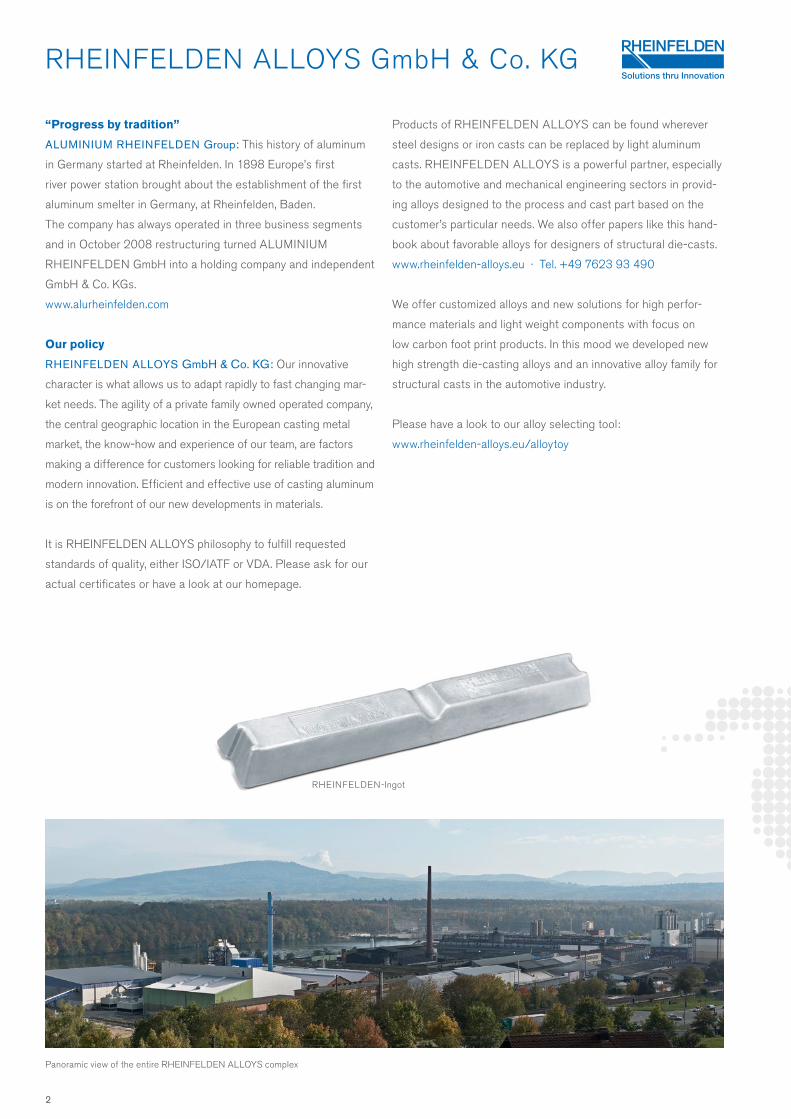
Panoramic view of the entire RHEINFELDEN ALLOYS complex
RHEINFELDEN-Ingot
2
R & D and Customer Support
When RHEINFELDEN ALLOYS develop new materials we always aim to achieve efficient and spe-
cific use of aluminum casts. Through the use of materials, tailored and refined to increase
performance, RHEINFELDEN ALLOYS helps to reduce vehicle weight and runs development proj-
ects with the goal to optimise the mechanical and casting properties of our aluminum HPDC alloys.
Our recent developed alloys are Silafont-38, Magsimal-plus, Castaduct-42 and Castaduct-18.
RHEINFELDEN Customer Support and RHEINFELDEN TechCenter
Every product and every customer has individual requirements of the material. The Customer
Support Team at RHEINFELDEN ALLOYS has the job of anticipating these needs and producing
tailored materials, fitting the casts and your requirements. Please contact our Customer Support
Team and use our TechCenter installations at RHEINFELDEN ALLOYS also for your foundry
concerns. We can advise on the use and design of casts and the choice of alloy. Use our experience
for your success as RHEINFELDEN ALLOYS customer.
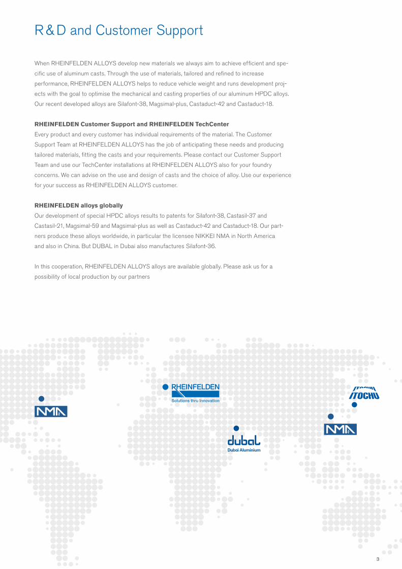
RHEINFELDEN alloys globally
Our development of special HPDC alloys results to patents for Silafont-38, Castasil-37 and
Castasil-21, Magsimal-59 and Magsimal-plus as well as Castaduct-42 and Castaduct-18. Our part-
ners produce these alloys worldwide, in particular the licensee NIKKEI NMA in North America
and also in China. But DUBAL in Dubai also manufactures Silafont-36.
In this cooperation, RHEINFELDEN ALLOYS alloys are available globally. Please ask us for a
possibility of local production by our partners
3
Alloys for Structural Casts by RHEINFELDEN ALLOYS
Structural components
Casted structural components are mostly large, but always stability
defining parts. They fulfill the idea of lightweight by dimensional
stability and functional integration. In the case of a crash high energy
absorption is recommended.
Dimensional stability is during the production process positively influenced by
• Easy castability
• Suitable die-cast design
• High strength achieved without heat treatment
RHEINFELDEN ALLOYS, as alloy producer support the use of
casted structural components and developed several HPDC
alloys for that purpose. Silafont-36, Castaman-35 as AlSi10MnMg
alloys are established since years. This handbook summarizes
the new alloys for structural casts.
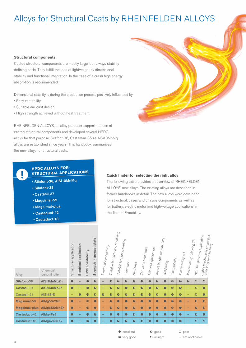
Quick finder for selecting the right alloy
The following table provides an overview of RHEINFELDEN
ALLOYS’ new alloys. The existing alloys are described in
former handbooks in detail. The new alloys were developed
for structural, cases and chassis components as well as
for battery, electric motor and high-voltage applications in
the field of E-mobility.
excellent
very good
good
all right
poor
— not applicable
AlloyChemical denomination S
truc
tura
l app
licat
ion
Ele
ctri
cal a
pplic
atio
n
HP
DC
cas
tabi
lity
Str
engt
h in
as-
cast
sta
te
Ele
ctric
al c
ondu
ctiv
ityS
uita
ble
for t
echn
ical
ano
disi
ngS
uita
ble
for p
unch
riv
etin
gE
long
atio
n
Har
dnes
s
Cor
rosi
on re
sist
ance
Impa
ct to
ughn
ess /
duc
tility
Wel
dabi
lity
Flan
geab
ility
Mac
hina
bilit
y at
FM
achi
nabi
lity
follo
win
g T6
Hig
h te
mpe
ratu
re a
pplic
atio
nS
tabl
e m
echa
nica
l pro
pert
ies
a
fter
long
-tim
e he
atin
g
Thin
wal
l app
licat
ion
Silafont-38 AlSi9MnMgZn – –
Castasil-37 AlSi9MnMoZr – – –
Castasil-21 AlSi9SrE – –
Magsimal-59 AlMg5Si2Mn – – –
Magsimal-plus AlMg6Si2MnZr – – –
Castaduct-42 AlMg4Fe2 – – –
Castaduct-18 AlMg4Zn3Fe2 – – –
HPDC ALLOYS FOR
STRUCTURAL APPLICATIONS
• Silafont-36, AlSi10MnMg
• Silafont-38
• Castasil-37
• Magsimal-59
• Magsimal-plus
• Castaduct-42
• Castaduct-18
4
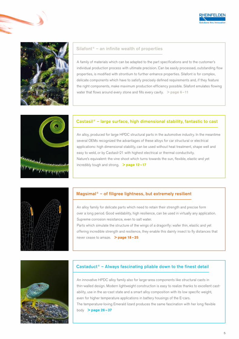
An alloy, produced for large HPDC structural parts in the automotive industry. In the meantime
several OEMs recognized the advantages of these alloys for car structural or electrical
applications: high dimensional stability, can be used without heat treatment, shape well and
easy to weld, or by Castasil-21 with highest electrical or thermal conductivity.
Nature’s equivalent: the vine shoot which turns towards the sun, flexible, elastic and yet
incredibly tough and strong. > page 12 – 17
Castasil ® – large surface, high dimensional stability, fantastic to cast
A family of materials which can be adapted to the part specifications and to the customer’s
individual production process with ultimate precision. Can be easily processed, outstanding flow
properties, is modified with strontium to further enhance properties. Silafont is for complex,
delicate components which have to satisfy precisely defined requirements and, if they feature
the right components, make maximum production efficiency possible. Silafont emulates flowing
water that flows around every stone and fills every cavity. > page 6 – 11
Silafont ® – an infinite wealth of properties
An alloy family for delicate parts which need to retain their strength and precise form
over a long period. Good weldability, high resilience, can be used in virtually any application.
Supreme corrosion resistance, even to salt water.
Parts which simulate the structure of the wings of a dragonfly: wafer thin, elastic and yet
offering incredible strength and resilience, they enable this dainty insect to fly distances that
never cease to amaze. > page 18 – 25
Magsimal ® – of filigree lightness, but extremely resilient
An innovative HPDC alloy family also for large-area components like structural casts in
thin-walled design. Modern lightweight construction is easy to realize thanks to excellent cast-
ability, use in the as-cast state and a smart alloy composition with its low specific weight,
even for higher temperature applications in battery housings of the E-cars.
The temperature-loving Emerald lizard produces the same fascination with her long flexible
body > page 26 – 37
Castaduct ® – Always fascinating pliable down to the finest detail
5
Silafont®-38 (Sf-38) An infinite wealth of properties
The HPDC alloy Silafont-38 was developed by RHEIN-
FELDEN ALLOYS to further increase yield strength
compared to Silafont-36 without significant change in
ductility.
Several hardening elements are alloyed in defined ranges in
the Silafont-38. That’s the cause why the advantage is with
a T6 heat treatment. The first step – solutionizing – is still
necessary, but the cooling may differ.
Even with an air quenching to lower distortion the complex
alloyed Silafont-38 reaches 180 MPa yield strength after
artificial aging.
Besides these moderate cooling rates it is possible to
cool down with water after the solutionizing treatment
to achive highest strength.
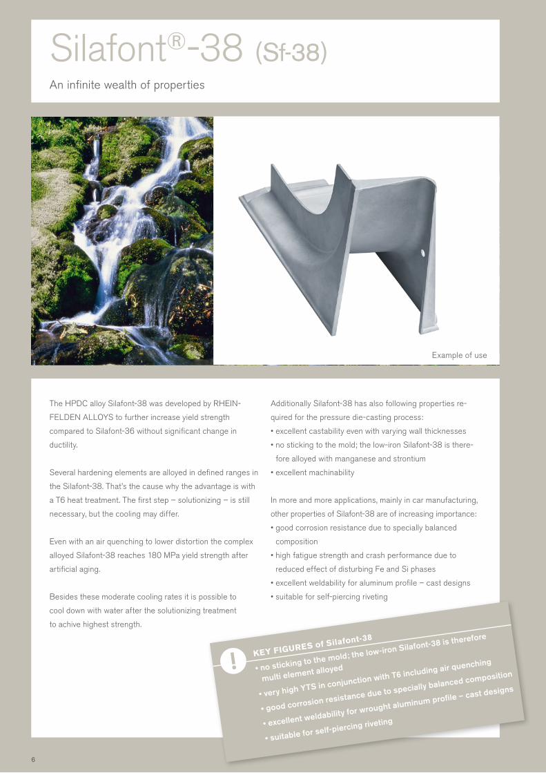
Additionally Silafont-38 has also following properties re-
quired for the pressure die-casting process:
• excellent castability even with varying wall thicknesses
• no sticking to the mold; the low-iron Silafont-38 is there-
fore alloyed with manganese and strontium
• excellent machinability
In more and more applications, mainly in car manufacturing,
other properties of Silafont-38 are of increasing importance:
• good corrosion resistance due to specially balanced
composition
• high fatigue strength and crash performance due to
reduced effect of disturbing Fe and Si phases
• excellent weldability for aluminum profile – cast designs
• suitable for self-piercing riveting
KEY FIGURES of Silafont-38
• no sticking to the mold; the low-iron Silafont-38 is therefore
multi element alloyed
• very high YTS in conjunction with T6 including air quenching
• good corrosion resistance due to specially balanced composition
• excellent weldability for wrought aluminum profile – cast designs
• suitable for self-piercing riveting
Example of use
6
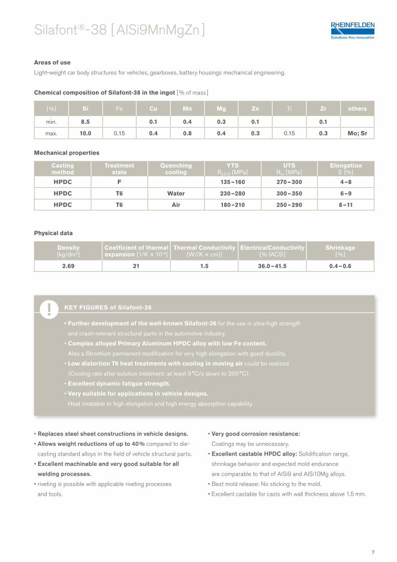
Areas of use
Light-weight car body structures for vehicles, gearboxes, battery housings mechanical engineering.
Chemical composition of Silafont-38 in the ingot [ % of mass ]
Mechanical properties
Physical data
Silafont ®- 38 [ AlSi9MnMgZn ]
Casting method
Treatment state
Quenching cooling
YTSRp0.2 [MPa ]
UTSRm [ MPa ]
ElongationE [ % ]
HPDC F 135 – 160 270 – 300 4 – 8
HPDC T6 Water 230 – 280 300 – 350 6 – 9
HPDC T6 Air 180 – 210 250 – 290 8 – 11
[ %] Si Fe Cu Mn Mg Zn Ti Zr others
min. 8.5 0.1 0.4 0.3 0.1 0.1
max. 10.0 0.15 0.4 0.8 0.4 0.3 0.15 0.3 Mo; Sr
Density [ kg/dm3 ]
Coefficient of thermal expansion [ 1/K × 10-6]
Thermal Conductivity [W/(K × cm)]
ElectricalConductivity [ % IACS ]
Shrinkage [ % ]
2.69 21 1.5 36.0 – 41.5 0.4 – 0.6
KEY FIGURES of Silafont-38
• Further development of the well-known Silafont-36 for the use in ultra-high strength
and crash-relevant structural parts in the automotive industry.
• Complex alloyed Primary Aluminum HPDC alloy with low Fe content.
Also a Strontium permanent modification for very high elongation with good ductility.
• Low distortion T6 heat treatments with cooling in moving air could be realized
(Cooling rate after solution treatment: at least 3 °C/s down to 200 °C).
• Excellent dynamic fatigue strength.
• Very suitable for applications in vehicle designs.
Heat treatable to high elongation and high energy absorption capability.
• Replaces steel sheet constructions in vehicle designs.
• Allows weight reductions of up to 40 % compared to die-
casting standard alloys in the field of vehicle structural parts.
• Excellent machinable and very good suitable for all
welding processes.
• riveting is possible with applicable riveting processes
and tools.
• Very good corrosion resistance:
Coatings may be unnecessary.
• Excellent castable HPDC alloy: Solidification range,
shrinkage behavior and expected mold endurance
are comparable to that of AlSi9 and AlSi10Mg alloys.
• Best mold release: No sticking to the mold.
• Excellent castable for casts with wall thickness above 1.5 mm.
7
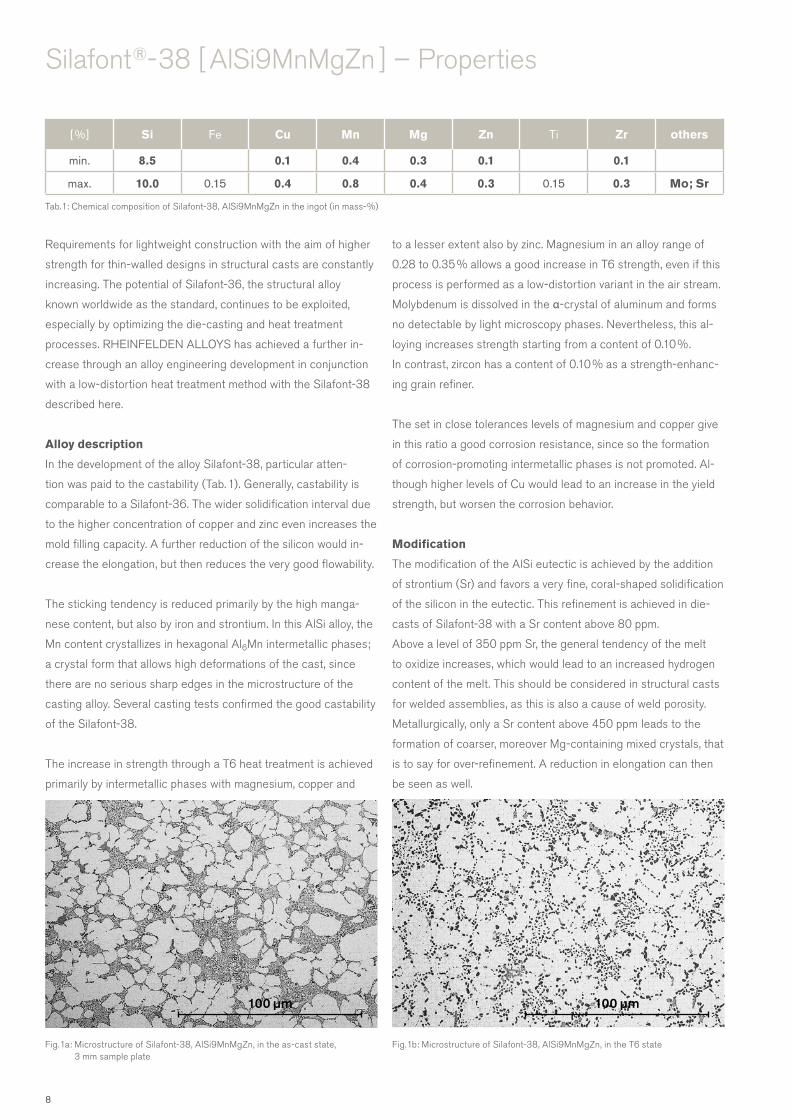
100 µm 100 µm
Silafont ®- 38 [ AlSi9MnMgZn ] – Properties
Tab. 1: Chemical composition of Silafont-38, AlSi9MnMgZn in the ingot (in mass-%)
[ %] Si Fe Cu Mn Mg Zn Ti Zr others
min. 8.5 0.1 0.4 0.3 0.1 0.1
max. 10.0 0.15 0.4 0.8 0.4 0.3 0.15 0.3 Mo; Sr
Fig. 1b: Microstructure of Silafont-38, AlSi9MnMgZn, in the T6 stateFig. 1a: Microstructure of Silafont-38, AlSi9MnMgZn, in the as-cast state, 3 mm sample plate
Requirements for lightweight construction with the aim of higher
strength for thin-walled designs in structural casts are constantly
increasing. The potential of Silafont-36, the structural alloy
known worldwide as the standard, continues to be exploited,
especially by optimizing the die-casting and heat treatment
processes. RHEINFELDEN ALLOYS has achieved a further in-
crease through an alloy engineering development in conjunction
with a low-distortion heat treatment method with the Silafont-38
described here.
Alloy description
In the development of the alloy Silafont-38, particular atten-
tion was paid to the castability (Tab. 1). Generally, castability is
comparable to a Silafont-36. The wider solidification interval due
to the higher concentration of copper and zinc even increases the
mold filling capacity. A further reduction of the silicon would in-
crease the elongation, but then reduces the very good flowability.
The sticking tendency is reduced primarily by the high manga-
nese content, but also by iron and strontium. In this AlSi alloy, the
Mn content crystallizes in hexagonal Al6Mn intermetallic phases;
a crystal form that allows high deformations of the cast, since
there are no serious sharp edges in the microstructure of the
casting alloy. Several casting tests confirmed the good castability
of the Silafont-38.
The increase in strength through a T6 heat treatment is achieved
primarily by intermetallic phases with magnesium, copper and
to a lesser extent also by zinc. Magnesium in an alloy range of
0.28 to 0.35 % allows a good increase in T6 strength, even if this
process is performed as a low-distortion variant in the air stream.
Molybdenum is dissolved in the α-crystal of aluminum and forms
no detectable by light microscopy phases. Nevertheless, this al-
loying increases strength starting from a content of 0.10 %.
In contrast, zircon has a content of 0.10 % as a strength-enhanc-
ing grain refiner.
The set in close tolerances levels of magnesium and copper give
in this ratio a good corrosion resistance, since so the formation
of corrosion-promoting intermetallic phases is not promoted. Al-
though higher levels of Cu would lead to an increase in the yield
strength, but worsen the corrosion behavior.
Modification
The modification of the AlSi eutectic is achieved by the addition
of strontium (Sr) and favors a very fine, coral-shaped solidification
of the silicon in the eutectic. This refinement is achieved in die-
casts of Silafont-38 with a Sr content above 80 ppm.
Above a level of 350 ppm Sr, the general tendency of the melt
to oxidize increases, which would lead to an increased hydrogen
content of the melt. This should be considered in structural casts
for welded assemblies, as this is also a cause of weld porosity.
Metallurgically, only a Sr content above 450 ppm leads to the
formation of coarser, moreover Mg-containing mixed crystals, that
is to say for over-refinement. A reduction in elongation can then
be seen as well.
8

Mg2SiQ_Prime
β"β_Prime
B_Prime
100 °C/min 10 °C/min
Silafont ®- 38 [ AlSi9MnMgZn ]
Fig. 3: Cooling curves with different cooling agents at 3 mm HPDC platesFig. 2: Calculated phase diagram for the time temperature curves of the different MgSi precipitations in Silafont-38
Metallography and phase simulation
In Fig. 1a, metallographic microstructures from the die-casted
alloy are shown in 500-times magnification. In condition F, a very
fine eutectic can be seen, which allows a very high deformability
already in the as-cast state. Intermetallic phases are under
10 microns in size, thus very small and evenly distributed.
The solidification of Silafont-38 starts with the Al6Mn-containing
phase at about 600 °C. Essential for the alloy, however, is the
formation of the modified Al-Si eutectic at 550 °C. A fine distribu-
tion of the AlMnFeSi phase is necessary for a high ductility and
is typically maintained in the die-cast structure with an Mn
content of between 0.4 and 0.8 %. The intermetallic Zr phases
also influence a fine structure of the Silafont-38.
For strength, submicroscopic precipitates in the Al solid solution
are essential. Such precipitates can be calculated using a phase
simulation. Fig. 2 shows the metastable MgSi phases, which
decisively influence the strength. For their shape, the initial state
of the material produced by the casting process, the solution
annealing and the quenching condition is important. If they have
a suitable size, they lead to high strength of the casting material.
Heat treatment
In the TechCenter Rheinfelden die-casted plates of dimension
200 × 60 mm are poured and T6 heat treated (Fig. 1b). An ad-
justment of the material characteristics achievable on 3 mm test
plates with large-area structural casts took place. The mold filling
of these panels resembles that of high-quality cast large struc-
tural casts more than might be expected. A significant difference
is the quench rate after removal from the mold or after the heat
treatment. Small plates can quench significantly faster, which
has an effect on material properties. The achievable strengths,
especially at the yield strength, increase considerably. For this
reason, a heat treatment installation has been built up which ap-
proximates the quenching conditions of an industrial production.
The quench rate was set at 3 °C/s for this laboratory method.
Fig. 3 shows temperature curves of 3 mm plates at different
quenching conditions. Clearly, the rapid temperature cooling
when immersed in water can be seen. After removal from the
oven, the onset of cooling only delayed by 8 seconds. The
different measuring curves when cooling with air are also due
to the different intensity of the air flow. In terms of metallurgy,
it is important to cool down to around 200 °C, below which the
cooling may then proceed more slowly.
With this determination, material characteristics such as Tab. 2
and Fig. 4 could be measured on test plates in the TechCenter.
These are comparable to those from typical industrial production
processes.
Silafont-38 can also be cooled down after solution annealing
with a considerably faster air cooling, as well as with the special
water-polymer cooling Aluquench®. The material characteristic
values are shown as the mean value of about 50 samples each
in Tab. 3. The respective increase of the yield strength from the
solution annealed state follows the higher cooling rates of these
processes.
Typically, with faster cooling, the distortion increases due to
higher residual stresses. Only the water-polymer cooling of the
Silafont-38 achieves maximum strength without significant
distortion. With water cooling, there is always a higher distortion
of the structural cast geometry.
0
100
200
300
400
500
600
0 50 100 150 200 250
Tem
pera
ture
[°C
]
Time [s]
Air flow
Water HISAQ
Air
9

Silafont ®- 38 [ AlSi9MnMgZn ] – Properties
Casting Method Treatmentstate
Quenching cooling
YTSRp0.2 [MPa ]
UTSRm [ MPa ]
ElongationE [ % ]
HPDC F 138 299 8.4
HPDC T6 Air 3 °C/s 192 264 10.5
HPDC T6 Air > 10 °C/s 209 288 11.0
HPDC T6 Aluquench 257 332 10.0
HPDC T6 Water 272 344 6.0
Tab. 3: Mechanical properties of Silafont 38, AlSi9MnMgZn in the T6 state and with different cooling agents
350
300
250
200
150
100
50
00 2 4 6 8 10 12
Elongation E [ %]
Str
ess
R [
MP
a ]
T 6 Air
F
T 6Water
Temper T6 Air
YTS = 185 MPa
UTS = 278 MPa
E = 10 %
Temper T6 Water
YTS = 272 MPa
UTS = 344 MPa
E = 6 %
Temper F
YTS = 147 MPa
UTS = 290 MPa
E = 5.5 %
Fig. 4: Stress-strain curve for Silafont-38, AlSi9MnMgZr, as-cast state and T6 cooled with air or water
Casting Method Treatmentstate
Quenching cooling
YTSRp0.2 [MPa ]
UTSRm [ MPa ]
ElongationE [ % ]
HPDC F 138 299 8.4
Standard deviation 3 8 0.8
HPDC T5 Water 220 317 6.2
Standard deviation 4 7 0.3
HPDC T6 Air 3 °C/s 192 264 10.5
Standard deviation 9 7 1.4
Tab. 2: Mechanical properties of Silafont-38, AlSi9MnMgZr plates in comparison F to T5 water cooled and T6 air cooled; the standard deviation is calculated of 50 casts
10
Silafont ®- 38 [ AlSi9MnMgZn ]
This shows the importance of the high alloy content in the
Silafont-38 in order to achieve the requirements of mechanical
properties with minimal component distortion.
Short-term and long-term stability
Aging of the casts is tested by testing at 205 °C for 1 hour and
at 150 °C for 1000 hours. Thereafter, the mechanical proper-
ties of the components made of Silafont-38 must not have fallen
below the specifications of mechanical strength.
Silafont-38 has passed this after heat treatment with the air
quenching used here at 3 °C/s after solution annealing.
Rivetability
The strength of a material affects the rivetability. Materials
with higher strengths must be joined with other rivets than
materials with low strengths. For this reason, the rivet geometry
and parameters of the die-casting alloy Silafont-38 have been
adjusted. The high deformability of the Silafont-38 led to crack-
free riveted joints.
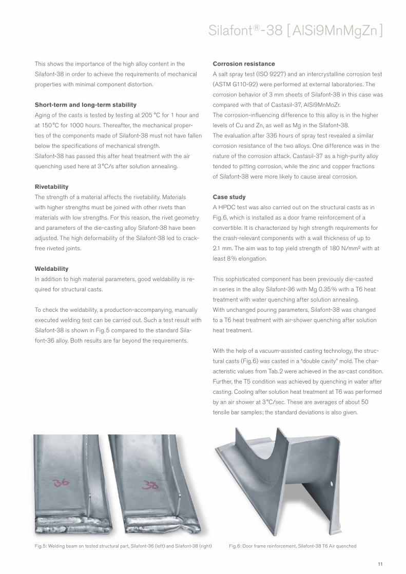
Weldability
In addition to high material parameters, good weldability is re-
quired for structural casts.
To check the weldability, a production-accompanying, manually
executed welding test can be carried out. Such a test result with
Silafont-38 is shown in Fig. 5 compared to the standard Sila-
font-36 alloy. Both results are far beyond the requirements.
Corrosion resistance
A salt spray test (ISO 9227) and an intercrystalline corrosion test
(ASTM G110-92) were performed at external laboratories. The
corrosion behavior of 3 mm sheets of Silafont-38 in this case was
compared with that of Castasil-37, AlSi9MnMoZr.
The corrosion-influencing difference to this alloy is in the higher
levels of Cu and Zn, as well as Mg in the Silafont-38.
The evaluation after 336 hours of spray test revealed a similar
corrosion resistance of the two alloys. One difference was in the
nature of the corrosion attack. Castasil-37 as a high-purity alloy
tended to pitting corrosion, while the zinc and copper fractions
of Silafont-38 were more likely to cause areal corrosion.
Case study
A HPDC test was also carried out on the structural casts as in
Fig. 6, which is installed as a door frame reinforcement of a
convertible. It is characterized by high strength requirements for
the crash-relevant components with a wall thickness of up to
2.1 mm. The aim was to top yield strength of 180 N/mm² with at
least 8 % elongation.
This sophisticated component has been previously die-casted
in series in the alloy Silafont-36 with Mg 0.35 % with a T6 heat
treatment with water quenching after solution annealing.
With unchanged pouring parameters, Silafont-38 was changed
to a T6 heat treatment with air-shower quenching after solution
heat treatment.
With the help of a vacuum-assisted casting technology, the struc-
tural casts (Fig. 6) was casted in a “double cavity” mold. The char-
acteristic values from Tab. 2 were achieved in the as-cast condition.
Further, the T5 condition was achieved by quenching in water after
casting. Cooling after solution heat treatment at T6 was performed
by an air shower at 3 °C/sec. These are averages of about 50
tensile bar samples; the standard deviations is also given.
Fig. 5: Welding beam on tested structural part, Silafont-36 (left) and Silafont-38 (right) Fig. 6: Door frame reinforcement, Silafont-38 T6 Air quenched
11

Castasil®-37 (Ci-37)Large areas, high dimensional stability, fantastic to cast
Development by RHEINFELDEN ALLOYS Castasil-37
shows good mechanical properties, especially elongation,
which are superior to those of conventional AlSi-type
alloys. Out-standing castability and weldability enable the
casting of complex designs. Self-piercing riveting trials
in the as-cast state led for example to good results.
The properties are mainly influenced by alloying with silicon,
manganese, molybdenum and strontium. A low magnesium
content is essential for the excellent stability of long-term
stability of mechanical properties.
Specially chosen chemical composition enables the
following casting properties:
• excellent castability
• suitable for minimum wall thicknesses
• no sticking to the mold
With increasing number of applications, mainly in car
manufacturing, other properties of Castasil-37 became
also important:
• high fatigue strength
• very good corrosion resistance
• excellent weldability
• excellent machinability
• suitable for self-piercing riveting
• suitable for adhesive bonding applications
KEY FIGURES of Castasil-37
• suitable for different wall thicknesses
• highest fatigue strength compared to AlSi-alloys
• very good corrosion resistance
• no aging, best dimensional stability in as-cast
• suitable for adhesive bonding applications
Example of use
12
Castasil ®- 37 [ AlSi9MnMoZr ]
Wall thickness [ mm ]
YTSRp0.2 [MPa ]
UTSRm [ MPa ]
ElongationE [ % ]
2 – 3 120 – 150 260 – 300 10 – 14
3 – 5 100 – 130 230 – 280 10 – 14
5 – 7 80 – 110 200 – 250 10 – 14
Density [ kg/dm3 ]
Coefficient of thermal expansion [ 1/K × 10-6]
Thermal Conductivity [W/(K × cm)]
ElectricalConductivity [ % IACS ]
Shrinkage [ % ]
2.69 22 1.4 31.0 – 38.0 0.4 – 0.6
[ %] Si Fe Cu Mn Mg Zn Mo Zr Ti Sr others
min. 8.5 0.35 0.1 0.1 0.006
max. 10.5 0.15 0.05 0.6 0.06 0.07 0.3 0.3 0.15 0.025 0.10
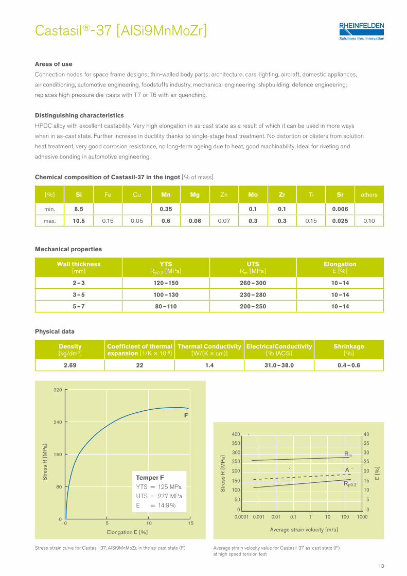
Areas of use
Connection nodes for space frame designs; thin-walled body parts; architecture, cars, lighting, aircraft, domestic appliances,
air conditioning, automotive engineering, foodstuffs industry, mechanical engineering, shipbuilding, defence engineering;
replaces high pressure die-casts with T7 or T6 with air quenching.
Distinguishing characteristics
HPDC alloy with excellent castability. Very high elongation in as-cast state as a result of which it can be used in more ways
when in as-cast state. Further increase in ductility thanks to single-stage heat treatment. No distortion or blisters from solution
heat treatment, very good corrosion resistance, no long-term ageing due to heat, good machinability, ideal for riveting and
adhesive bonding in automotive engineering.
Chemical composition of Castasil-37 in the ingot [ % of mass]
Mechanical properties
Physical data
Stress-strain curve for Castasil-37, AlSi9MnMoZr, in the as-cast state (F)
Elongation E [ %]
Str
ess
R [
MP
a]
Temper F
YTS = 125 MPa
UTS = 277 MPa
E = 14.9 %
F
Average strain velocity value for Castasil-37 as-cast state (F) at high speed tension test
Str
ess
R [
MP
a]
Average strain velocity [m/s]
0.01 1000.0001 1
400
350
300
250
200
150
100
50
01000100.10.001
Rp0.2
40
35
30
25
20
15
10
5
0
A
E [
%]
Rm
13

Castasil-21 is a HPDC alloy developed by RHEINFELDEN
ALLOYS for casts with outstanding requirements in terms
of electrical or thermal conductivity.
Aluminum 99.7E for rotors has indeed higher electrical
conductivity, but in praxis you need lower contraction for
huge casts, like with an alloy with more than 8 % silicon.
The application of Castasil-21 may help to lower the weight
of HPDC, especially for the light weight design of cars
with their additional casts like battery housing, conductor
plate for electronics, LED-lighting, but also for general
purposes of heating and cooling.
Chemical composition was optimized in order to have high
conductivity (up to 30 %) compared with usual HPDC
aluminum alloys and still around 10 % higher than with
Silafont-36.
The specially chosen chemical composition results in
following casting properties:
• excellent casting ability with good ejectability
• well usable for thin wall fins
More and more applications either in car design or in
telecommunication area need also following properties:
• very good corrosion resistance to weather
• good mechanical strength compared to Al for rotors
• excellent machinability
• flangeable or deformable to fix parts together
• suitable for adhesive bonding applications
• electrical conductivity comes up to 48.5 % IACS,
to substitute Cu in the idea of light weight design or
Al 99.7E in rotors
Castasil®-21 (Ci-21)Large areas, high dimensional stability, fantastic to cast
KEY FIGURES of Castasil-21
• well usable for thin wall fins
• very good corrosion resistance to weathering
• good mechanical strength; excellent machinability
• electrical conductivity comes up to 48.5 % IACS,
to substitute Cu in the idea of light weight design
or Al 99.7E in rotors
Example of use
14
Castasil ®- 21 [ AlSi9SrE ]
Temper YTSRp0.2 [MPa ]
UTSRm [ MPa ]
ElongationE [ % ]
Brinell hardness[ HBW ]
F 85 – 100 200 – 230 6 – 9 55 – 70
O 80 – 100 170 – 200 9 – 15 55 – 65
[ %] Si Fe Cu Mn Mg Zn Ti Sr others
min. 8.0 0.5 0.01
max. 9.0 0.7 0.02 0.01 0.03 0.07 0.01 0.03 0.10
Areas of use
Also for all kind of casts with requirements in terms of high thermal or electrical conductivity. Conductor plate for electronics,
automotive and mechanical engineering, LED-lighting, air cooling, electronic boxes or covers, E-mobil applications, inclusive
electric engines.
Chemical composition of Castasil-21 in the ingot [ % of mass]
Mechanical properties
Physical data
Density [ kg/dm3 ]
Coefficient of thermal expansion [ 1/K × 10-6]
Thermal Conductivity [W/(K × cm)]
ElectricalConductivity [ % IACS ]
Shrinkage [ % ]
2.69 22 1.9 43.0 – 48.5 0.4 – 0.6
• Very good values for the elongation at state O: Elongation
up to 15 %.
• Excellent machinable and very suitable for welding processes.
• Suitable for crimping processes.
• Excellent castable HPDC alloy. Solidification range,
shrinkage behavior and expected die-casting mold endurance
are comparable to that of AlSi9 and AlSi10Mg alloys.
• Existing die-casting cells for AlSi alloys must not be modified.
• Well suited for casts with minimum wall thickness (from
1.5 mm).
• Very low heat cracking tendency and very good release
properties.
KEY FIGURES of Castasil-21
• Very good electrical conductivity: 25 to 28 MS/m (43.0 to 48.5 % IACS) in the state O
• Very good thermal conductivity: 1.6 to in the state O 1.9 W/K × cm
Annealing of casts for the state O leads to the highest conductivities compared to other AlSi HPDC alloys.
• Very good corrosion resistance to water and weather. Coatings are often not necessary.
15

Castasil ®- 21 [ AlSi9SrE ] – Properties
Chemical composition
Table 1 shows the Castasil-21 composition with a silicon content
of 8 to 9 %. Thus, the processing temperature is 680 – 750 °C,
an area with typical thermal shock wear of casting chamber and
cavity. Strontium causes a further lowering of the eutectic point,
that is the melting temperature, of about 6 – 8 °C. In die-casting
alloys Strontium reduces the affinity of the melt to the mold, i.e.
the tendency to stick on, although Castasil-21 is already alloyed
with an Fe content from 0.5 to 0.7 %.
As an impurity in this conductive alloy are magnesium and zinc
contents of more than 0.08 % and a copper content more than
0.02 %. While forming the conductivity disturbing solid solution
phases these elements are already at lower levels, but this is
negligible compared to the effects from the die-casting process
(Fig. 1). Not so with the manganese and titanium content.
Here a value of only 0.01 % should not be exceeded in order to
keep the conductivity high. Because Castasil-21 is produced
with primary aluminum as base, further accompanying elements
are also kept very low.
Electrical conductivity
But more important is the modification of the silicon crystal during
solidification. The strontium addition causes a coralline
solidification structure of the Si crystal in the eutectic, the so
called modification. The relevant Castasil-21 advantage of this
modification is the higher conductivity of plus 2 – 4 MS /m.
Heat treatment
The processing in the die-casting is characterized by a very rapid
solidification. Although this achieves higher strength and hard-
ness, this microstructure is negative for achieving high conductiv-
ity ! Casts out of Castasil-21 can even further be increased
in their conductivity by one-stage heat treatment, whereby
the internal stress of the cast structure is equalized then. In the
as-cast state a die-cast with 6 mm wall thickness may reach
even 25 MS/m.
A heat treatment of 350 °C for 2 h or 250 °C for 3 h provides
superior conductivity of around 28 MS/m (Fig. 2). In this state,
the die-casts have 83 % of the conductivity of Al 99.7E. Upon
the cooling of the components after the stress-relieving may
only slowly air cooling to be made.
Handling instructions
Cleaning and processing the melt should result in a low achieved
oxide impurity. A strontium content of 100 to 350 ppm ensures
the modification. Ingate design and die-cast parameters must be
optimized to result in a solid structure without pores, due to these
technically disturb the conductivity. Please look for handling
instructions for details of melt preparation.
Ele
ctric
al c
ondu
ctiv
ity [
MS
/m ]
353433323130292827262524232221201918171615
AlSi12(Fe) 170 °C 250 °C 350 °C Al for rotors
1h 2 h 3 hFF F 1h 2 h 3 h 1h 2 h 3 h
Castasil-21
Con
duct
ivity
[M
S/m
]
Content of alloying element [ %]
35
30
25
20
15
10
Cr Mn
ZrTi
Cu
FeZn
Si
0 0.2 0.4 0.6 0.8 1.0 1.2 1.4
37
Tab. 1: Chemical composition of Castasil-21, AlSi9SrE in the ingot (in mass-%)
Fig. 1: Relationship between electrical conductivity of Al99.9 and added alloying elements
Fig. 2: Electrical conductivity of Castasil-21 through heat treatment of the HPDC
Mg
[ %] Si Fe Cu Mn Mg Zn Ti Sr others
min. 8.0 0.5 0.01
max. 9.0 0.7 0.02 0.01 0.03 0.07 0.01 0.03 0.10
16
Castasil ®- 21 [ AlSi9SrE ]
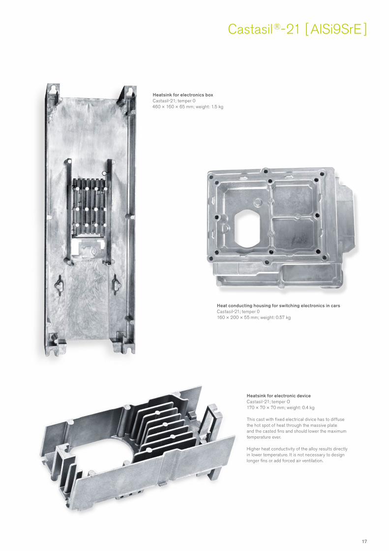
Heatsink for electronic deviceCastasil-21; temper O170 × 70 × 70 mm; weight: 0.4 kg
This cast with fixed electrical divice has to diffuse the hot spot of heat through the massive plate and the casted fins and should lower the maximum temperature ever.
Higher heat conductivity of the alloy results directly in lower temperature. It is not necessary to design longer fins or add forced air ventilation.
Heatsink for electronics boxCastasil-21; temper 0460 × 160 × 65 mm; weight: 1.5 kg
Heat conducting housing for switching electronics in carsCastasil-21; temper 0160 × 200 × 55 mm; weight: 0.57 kg
17

Magsimal® -59 (Ma-59)Of filigree lightness, but extremely resilient
Magsimal-59 developed by RHEINFELDEN ALLOYS
is a widely used HPDC alloy for automotive applications.
This alloy type has excellent properties in the as-cast state,
i.e. high yield strength in conjunction with high ductility.
High energy absorption capacity, e.g. in the event of a crash.
The fatigue strength is also higher than for conventional
pressure die-cast alloys.
Most applications are therefore safety components with
high performance requirements e.g. safety-belt pretensioners,
steering wheel frames, crossbeams, motorbike wheel rims,
control arm, suspension-strut brackets and other flap or
chassis components.
The properties of Magsimal-59 depend on the wall thickness
and on cooling method after HPDC. A one step heat treat-
ment is suggested to compensate these differences and to
result in up to 30 % higher YTS. Air quenching would be the
best, due it reduce distortions and results in high rigidity.
The alloy Magsimal-59 is produced on a primary metal
basis and therefore manifests high analytical purity.
This produces as a consequence outstanding mechanical
strength and an excellent corrosion behavior.
Specially chosen chemical composition enables the
following casting properties:
• very good castability
• suitable for minimum wall thicknesses
• low sticking to the mold
• excellent properties in the as-cast state
With increasing number of applications, mainly in car
manufacturing, other properties of Magsimal-59 became
also important:
• high yield strength in conjunction with high ductility
• very high energy absorption capacity
• excellent suitable for adhesive bonding applications
• very high fatigue strength
• excellent corrosion behavior
• suitable for self-piercing riveting
KEY FIGURES of Magsimal-59
• high yield strength in conjunction with high ductility
• very high energy absorption capacity
• excellent fatigue strength even with sea water contact
• excellent corrosion behavior
Example of use
18

Magsimal ®- 59 [ AlMg5Si2Mn ]
Areas of use
Architecture, cars, aircraft, domestic appliances, air conditioning, automotive engineering, foodstuffs industry,
mechanical engineering, optics and furniture, shipbuilding, chemical industry.
Distinguishing characteristics
HPDC alloy with excellent mechanical and dynamic properties with thin walls.
Very good weldability, suited to self-piercing riveting. Excellent corrosion resistance, excellent mechanical polishability
and good machinability, ideal adhesive bonding in car body design.
Chemical composition of Magsimal-59 in the ingot [ % of mass]
Mechanical properties
Physical data
Wall thickness [ mm ]
YTSRp0.2 [MPa ]
UTSRm [ MPa ]
ElongationE [ % ]
< 2 > 220 > 300 10 – 15
2 – 4 160 – 220 310 – 340 11 – 22
4 – 6 140 – 170 250 – 320 9 – 14
6 – 12 120 – 145 220 – 260 8 – 12
[ %] Si Fe Cu Mn Mg Zn Ti Be others
min. 1.8 0.5 5.0
max. 2.6 0.2 0.03 0.8 6.0 0.07 0.20 0.004 0.2
Density [ kg/dm3 ]
Coefficient of thermal expansion [ 1/K × 10-6]
Thermal Conductivity [W/(K × cm)]
ElectricalConductivity [ % IACS ]
Shrinkage [ % ]
2.65 24 1.1 24.0 – 27.5 0.6 – 1.1
Stress-strain curve for Magsimal-59, AlMg5Si2Mn, in the as-cast state. Wall thickness of samples: 3 mm
Elongation E [ %]
320
240
160
80
00 5 10 15 20
Str
ess
R [
MP
a]
Wöhler’s curve for Magsimal-59, AlMg5Si2Mn, in the as-cast state
105 106 107 108
200
180
160
140
120
100
80
60
40
20
0
Number of load cycles [n]
Str
ess
R [
MP
a]
Stress ratio r = -1Wall thickness 4 mm5 %, 50 %, 95 % fracture probability
95 %50 %
5 %
Temper F
YTS = 178 MPa
UTS = 313 MPa
E = 20.6 %
19
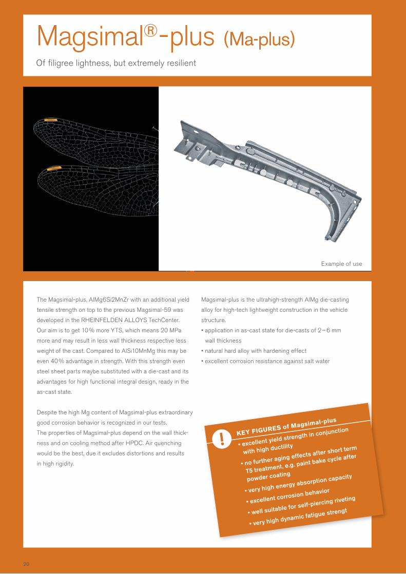
Magsimal® - plus (Ma-plus)Of filigree lightness, but extremely resilient
The Magsimal-plus, AlMg6Si2MnZr with an additional yield
tensile strength on top to the previous Magsimal-59 was
developed in the RHEINFELDEN ALLOYS TechCenter.
Our aim is to get 10 % more YTS, which means 20 MPa
more and may result in less wall thickness respective less
weight of the cast. Compared to AlSi10MnMg this may be
even 40 % advantage in strength. With this strength even
steel sheet parts maybe substituted with a die-cast and its
advantages for high functional integral design, ready in the
as-cast state.
Despite the high Mg content of Magsimal-plus extraordinary
good corrosion behavior is recognized in our tests.
The properties of Magsimal-plus depend on the wall thick-
ness and on cooling method after HPDC. Air quenching
would be the best, due it excludes distortions and results
in high rigidity.
Magsimal-plus is the ultrahigh-strength AlMg die-casting
alloy for high-tech lightweight construction in the vehicle
structure.
• application in as-cast state for die-casts of 2 – 6 mm
wall thickness
• natural hard alloy with hardening effect
• excellent corrosion resistance against salt water
KEY FIGURES of Magsimal-plus
• excellent yield strength in conjunction
with high ductility
• no further aging effects after short term
T5 treatment, e.g. paint bake cycle after
powder coating
• very high energy absorption capacity
• excellent corrosion behavior
• well suitable for self-piercing riveting
• very high dynamic fatigue strengt
Example of use
20

Magsimal ®- plus [ AlMg6Si2MnZr ]
Areas of use
Architecture, automotive or trucks, aircraft, domestic appliances, air conditioning, automotive engineering,
mechanical engineering, shipbuilding, chemical industry, substitution of complex steel sheet designs or forgings
Chemical composition of Magsimal-plus in the ingot [ % of mass]
Mechanical properties with 3 mm wall thickness
Physical data
[ %] Si Fe Cu Mn Mg Zn Ti Zr others
min. 2.1 0.5 6.0 0.1
max. 2.6 0.15 0.05 0.8 6.4 0.07 0.05 0.3 Mo; Be
Density [ kg/dm3 ]
Coefficient of thermal expansion [ 1/K × 10-6]
Thermal Conductivity [W/(K × cm)]
ElectricalConductivity [ % IACS ]
Shrinkage [ % ]
2.66 24 1.1 24.0 – 27.5 0.6 – 1.1
Treatment state
YTSRp0.2 [MPa ]
UTSRm [ MPa ]
ElongationE [ % ]
F 200 – 220 340 – 360 9 – 12
T5 230 – 250 350 – 380 8 – 12
KEY FIGURES of Magsimal-plus
• Magsimal-plus is an AlMgSi high pressure die-casting alloy with excellent mechanical properties
in the stabilized as-cast state for structural parts in the BIW of vehicles.
• The high strength of Magsimal-plus enables very thin lightweight designs. A weight reduction
up to 40 % in comparison to an AlSi10MnMg design may be achieved.
• No T6 or T7 heat treatment required: Cost cutting is possible due weight reduction of the cast and
due skipping heat treatment and straightening after heat treatment’s distortion.
• Excellent corrosion behavior.
• Advanced application range for casts in the as-cast state F.
• Very suitable for applications in vehicle designs: Excellent
energy absorption capacity in the event of a vehicle
crash or impact to battery trays and covers.
• Substitution of complex steel sheet designs in vehicle
designs is possible.
• Substitution of aluminum forgings in vehicle designs is possible.
• Excellent weldable, welding technique should be similar to
5000-series.
• Well suitable for self-piercing riveting, clinched joints and
adhesive bonds.
• Very high resistance to stress corrosion cracking.
Keep in mind:
• The casting of this alloy requires special casting
know-how in the die concept and attention to the specific
melting and casting technique.
21
100 µm
[ %] Si Fe Cu Mn Mg Zn Ti Zr others
min. 2.1 0.5 6.0 0.1
max. 2.6 0.15 0.05 0.8 6.4 0.07 0.05 0.3 Mo; Be
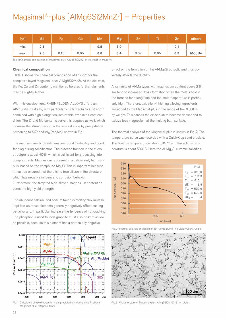
Tab. 1: Chemical composition of Magsimal-plus, AlMg6Si2MnZr in the ingot (in mass-%)
Magsimal ®- plus [ AlMg6Si2MnZr ] – Properties
Chemical composition
Table 1 shows the chemical composition of an ingot for the
complex alloyed Magsimal-plus, AlMg6Si2MnZr. At the die-cast,
the Fe, Cu and Zn contents mentioned here as further elements
may be slightly higher.
With this development, RHEINFELDEN ALLOYS offers an
AlMgSi die-cast alloy with particularly high mechanical strength
combined with high elongation, achievable even in as-cast con-
dition. The Zr and Mo contents serve this purpose as well, which
increase the strengthening in the as-cast state by precipitation
hardening to SiZr and Al12(Mn,Mo), shown in Fig 1.
The magnesium-silicon ratio ensures good castability and good
feeding during solidification. The eutectic fraction in the micro-
structure is about 40 %, which is sufficient for processing into
complex casts. Magnesium is present in a deliberately high sur-
plus, based on the compound Mg2Si. This is important because
it must be ensured that there is no free silicon in the structure,
which has negative influence to corrosion behavior.
Furthermore, the targeted high-alloyed magnesium content en-
sures the high yield strength.
The abundant calcium and sodium found in melting flux must be
kept low, as these elements generally negatively affect casting
behavior and, in particular, increase the tendency of hot cracking.
The phosphorus used to inert graphite must also be kept as low
as possible, because this element has a particularly negative
effect on the formation of the Al-Mg2Si eutectic and thus ad-
versely affects the ductility.
Alloy melts of Al-Mg types with magnesium content above 2 %
are tend to increased dross formation when the melt is hold in
the furnace for a long time and the melt temperature is particu-
larly high. Therefore, oxidation-inhibiting alloying ingredients
are added to the Magsimal-plus in the range of few 0.001 %
by weight. This causes the oxide skin to become denser and to
oxidize less magnesium at the melting bath surface.
The thermal analysis of the Magsimal-plus is shown in Fig. 2. The
temperature curve was recorded with a Quick-Cup sand crucible.
The liquidus temperature is about 615 °C and the solidus tem-
perature is about 590 °C. Here the Al-Mg2Si eutectic solidifies.
Fig. 3: Microstructure of Magsimal-plus, AlMg6Si2MnZr; 3 mm plates
Fig. 2: Thermal analysis of Magsimal-59, AlMg5Si2Mn, in a Quick-Cup-Crucible
0 2.5 5.0
640
630
620
610
600
590
580
570
560
550
540
Time [min]
Tem
pera
ture
[°C
]
[°C]
TG = 670.0TLu = 611.3TLo = 615.1dTL = 3.8TSu = 592.6TSo = 593.0dTS = 0.4
Fig. 1: Calculated phase diagram for main precipitations during solidification of Magsimal-plus, AlMg6Si2MnZr
22
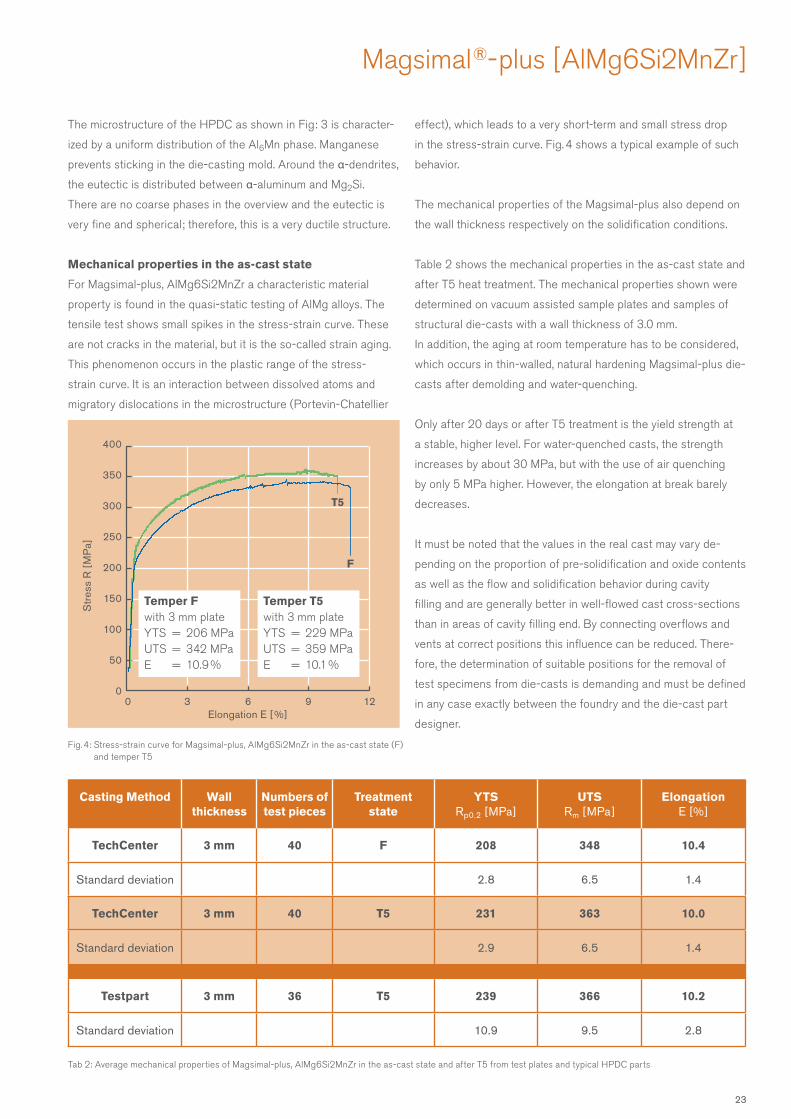
Fig. 4: Stress-strain curve for Magsimal-plus, AlMg6Si2MnZr in the as-cast state (F) and temper T5
Tab 2: Average mechanical properties of Magsimal-plus, AlMg6Si2MnZr in the as-cast state and after T5 from test plates and typical HPDC parts
Elongation E [ %]
Str
ess
R [
MP
a]
0 3 6 9 12
400
350
300
250
200
150
100
50
0
F
T5
Temper T5with 3 mm plateYTS = 229 MPaUTS = 359 MPaE = 10.1 %
Temper Fwith 3 mm plateYTS = 206 MPaUTS = 342 MPaE = 10.9 %
Magsimal ®- plus [ AlMg6Si2MnZr ]
The microstructure of the HPDC as shown in Fig: 3 is character-
ized by a uniform distribution of the Al6Mn phase. Manganese
prevents sticking in the die-casting mold. Around the α-dendrites,
the eutectic is distributed between α-aluminum and Mg2Si.
There are no coarse phases in the overview and the eutectic is
very fine and spherical; therefore, this is a very ductile structure.
Mechanical properties in the as-cast state
For Magsimal-plus, AlMg6Si2MnZr a characteristic material
property is found in the quasi-static testing of AlMg alloys. The
tensile test shows small spikes in the stress-strain curve. These
are not cracks in the material, but it is the so-called strain aging.
This phenomenon occurs in the plastic range of the stress-
strain curve. It is an interaction between dissolved atoms and
migratory dislocations in the microstructure (Portevin-Chatellier
effect), which leads to a very short-term and small stress drop
in the stress-strain curve. Fig. 4 shows a typical example of such
behavior.
The mechanical properties of the Magsimal-plus also depend on
the wall thickness respectively on the solidification conditions.
Table 2 shows the mechanical properties in the as-cast state and
after T5 heat treatment. The mechanical properties shown were
determined on vacuum assisted sample plates and samples of
structural die-casts with a wall thickness of 3.0 mm.
In addition, the aging at room temperature has to be considered,
which occurs in thin-walled, natural hardening Magsimal-plus die-
casts after demolding and water-quenching.
Only after 20 days or after T5 treatment is the yield strength at
a stable, higher level. For water-quenched casts, the strength
increases by about 30 MPa, but with the use of air quenching
by only 5 MPa higher. However, the elongation at break barely
decreases.
It must be noted that the values in the real cast may vary de-
pending on the proportion of pre-solidification and oxide contents
as well as the flow and solidification behavior during cavity
filling and are generally better in well-flowed cast cross-sections
than in areas of cavity filling end. By connecting overflows and
vents at correct positions this influence can be reduced. There-
fore, the determination of suitable positions for the removal of
test specimens from die-casts is demanding and must be defined
in any case exactly between the foundry and the die-cast part
designer.
Casting Method Wallthickness
Numbers of test pieces
Treatmentstate
YTSRp0.2 [MPa ]
UTSRm [ MPa ]
ElongationE [ % ]
TechCenter 3 mm 40 F 208 348 10.4
Standard deviation 2.8 6.5 1.4
TechCenter 3 mm 40 T5 231 363 10.0
Standard deviation 2.9 6.5 1.4
Testpart 3 mm 36 T5 239 366 10.2
Standard deviation 10.9 9.5 2.8
23
100 µm 2,049 mm
0,603 mm
1,008 mm
0,744 mm
1,773 mm
Mechanical properties after T5 treatment
A further increase in strength can be achieved by a T5 treatment
of the cast at only 200 °C in 30 – 60 minutes. It has been indi-
cated that the cast must be quenched immediately after demold-
ing from the die-casting mold, so that the appropriate increase in
strength during artificial ageing can be achieved. Only a cooling
in air after demolding does not achieve the full effect.
The increase in mechanical properties compared to the as-
cast state is shown in Fig. 4. These mechanical properties were
determined on 3.0 mm sample plates as well as on large-sized
structural die-casts, designed and manufactured to suit the alloy
features.
This short T5 artificial aging treatment thus significantly shortens
the otherwise waiting for natural aging.
In the automotive industry also demands on the short and long
term stability of the mechanical properties are made. Such aging
tests at 205 °C for 1 h or 150 °C for 1000 h, the casts from Magsi-
mal-plus has been successfully passed after short T5 treatment.
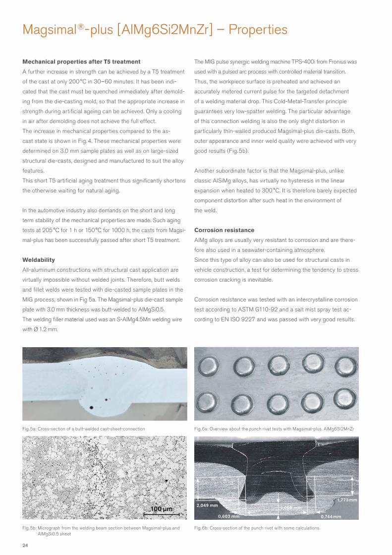
Weldability
All-aluminum constructions with structural cast application are
virtually impossible without welded joints. Therefore, butt welds
and fillet welds were tested with die-casted sample plates in the
MIG process, shown in Fig 5a. The Magsimal-plus die-cast sample
plate with 3.0 mm thickness was butt-welded to AlMgSi0.5.
The welding filler material used was an S - AlMg4.5Mn welding wire
with Ø 1.2 mm.
The MIG pulse synergic welding machine TPS-400i from Fronius was
used with a pulsed arc process with controlled material transition.
Thus, the workpiece surface is preheated and achieved an
accurately metered current pulse for the targeted detachment
of a welding material drop. This Cold-Metal-Transfer principle
guarantees very low-spatter welding. The particular advantage
of this connection welding is also the only slight distortion in
particularly thin-walled produced Magsimal-plus die-casts. Both,
outer appearance and inner weld quality were achieved with very
good results (Fig. 5b).
Another subordinate factor is that the Magsimal-plus, unlike
classic AlSiMg alloys, has virtually no hysteresis in the linear
expansion when heated to 300 °C. It is therefore barely expected
component distortion after such heat in the environment of
the weld.
Corrosion resistance
AlMg alloys are usually very resistant to corrosion and are there-
fore also used in a seawater-containing atmosphere.
Since this type of alloy can also be used for structural casts in
vehicle construction, a test for determining the tendency to stress
corrosion cracking is inevitable.
Corrosion resistance was tested with an intercrystalline corrosion
test according to ASTM G110-92 and a salt mist spray test ac-
cording to EN ISO 9227 and was passed with very good results.
Magsimal ®- plus [ AlMg6Si2MnZr ] – Properties
Fig. 5b: Micrograph from the welding beam section between Magsimal-plus and AlMgSi0.5 sheet
Fig. 5a: Cross-section of a butt-welded cast-sheet-connection
Fig. 6b: Cross-section of the punch rivet with some calculations
Fig. 6a: Overview about the punch rivet tests with Magsimal-plus, AlMg6Si2MnZr
24
Riveting capability
In body construction with its various materials, the connection
technology punch riveting plays a major role (Fig. 6a). In this
process semi-hollow punch rivets pierce the overhead steel or
aluminum sheet and dig into the cast (Fig. 6b).
The casting material must be able to withstand the deformations
on the closing head of the riveting mold. A further evaluation
is carried out at closely side by side placed rivets or with rivets
placed close to the cast’ edge in the demand for crack-free clos-
ing heads on the casted surface.
The rivet mold significantly influences the riveting result. The
semi-hollow punch riveting processes have to be optimized for
high-strength Magsimal-plus applications. Sections of the
cast intended for punch riveting should not be designed thinner
than 3 mm to have the required ductility.
Surface finishing
Magsimal-plus can be painted, powder-coated, polished or anod-
ized. Polishing results into a typical slight blue coloration of the
surface gloss. When anodizing, it should be noted that a gray
shade should be formed because of the low silicon content. For
decorative purposes, it is therefore advisable to use a chrome
layer or the polished surface.
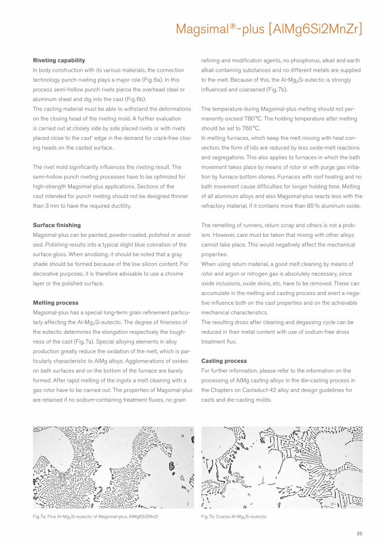
Melting process
Magsimal-plus has a special long-term grain refinement particu-
larly affecting the Al-Mg2Si eutectic. The degree of fineness of
the eutectic determines the elongation respectively the tough-
ness of the cast (Fig. 7a). Special alloying elements in alloy
production greatly reduce the oxidation of the melt, which is par-
ticularly characteristic to AlMg alloys. Agglomerations of oxides
on bath surfaces and on the bottom of the furnace are barely
formed. After rapid melting of the ingots a melt cleaning with a
gas rotor have to be carried out. The properties of Magsimal-plus
are retained if no sodium-containing treatment fluxes, no grain
refining and modification agents, no phosphorus, alkali and earth
alkali containing substances and no different metals are supplied
to the melt. Because of this, the Al-Mg2Si eutectic is strongly
influenced and coarsened (Fig. 7b).
The temperature during Magsimal-plus melting should not per-
manently exceed 780 °C. The holding temperature after melting
should be set to 760 °C.
In melting furnaces, which keep the melt moving with heat con-
vection, the form of lids are reduced by less oxide-melt reactions
and segregations. This also applies to furnaces in which the bath
movement takes place by means of rotor or with purge gas initia-
tion by furnace bottom stones. Furnaces with roof heating and no
bath movement cause difficulties for longer holding time. Melting
of all aluminum alloys and also Magsimal-plus reacts less with the
refractory material, if it contains more than 85 % aluminum oxide.
The remelting of runners, return scrap and others is not a prob-
lem. However, care must be taken that mixing with other alloys
cannot take place. This would negatively affect the mechanical
properties.
When using return material, a good melt cleaning by means of
rotor and argon or nitrogen gas is absolutely necessary, since
oxide inclusions, oxide skins, etc. have to be removed. These can
accumulate in the melting and casting process and exert a nega-
tive influence both on the cast properties and on the achievable
mechanical characteristics.
The resulting dross after cleaning and degassing cycle can be
reduced in their metal content with use of sodium-free dross
treatment flux.
Casting process
For further information, please refer to the information on the
processing of AlMg casting alloys in the die-casting process in
the Chapters on Castaduct-42 alloy and design guidelines for
casts and die-casting molds.
Magsimal ®- plus [ AlMg6Si2MnZr ]
Fig. 7a: Fine Al-Mg2Si-eutectic of Magsimal-plus, AlMg6Si2MnZr Fig. 7b: Coarse Al-Mg2Si-eutectic
25
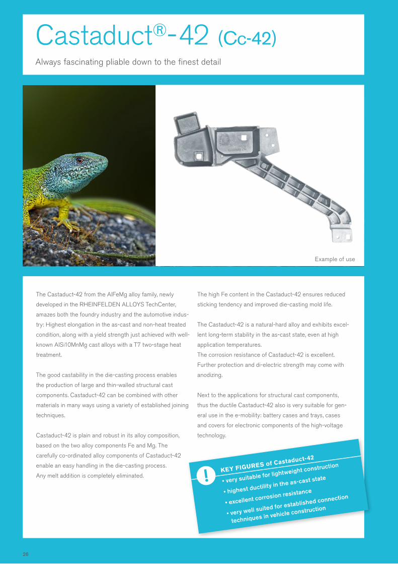
Castaduct®- 42 (Cc-42)Always fascinating pliable down to the finest detail
The Castaduct-42 from the AlFeMg alloy family, newly
developed in the RHEINFELDEN ALLOYS TechCenter,
amazes both the foundry industry and the automotive indus-
try: Highest elongation in the as-cast and non-heat treated
condition, along with a yield strength just achieved with well-
known AlSi10MnMg cast alloys with a T7 two-stage heat
treatment.
The good castability in the die-casting process enables
the production of large and thin-walled structural cast
components. Castaduct-42 can be combined with other
materials in many ways using a variety of established joining
techniques.
Castaduct-42 is plain and robust in its alloy composition,
based on the two alloy components Fe and Mg. The
carefully co-ordinated alloy components of Castaduct-42
enable an easy handling in the die-casting process.
Any melt addition is completely eliminated.
The high Fe content in the Castaduct-42 ensures reduced
sticking tendency and improved die-casting mold life.
The Castaduct-42 is a natural-hard alloy and exhibits excel-
lent long-term stability in the as-cast state, even at high
application temperatures.
The corrosion resistance of Castaduct-42 is excellent.
Further protection and di-electric strength may come with
anodizing.
Next to the applications for structural cast components,
thus the ductile Castaduct-42 also is very suitable for gen-
eral use in the e-mobility: battery cases and trays, cases
and covers for electronic components of the high-voltage
technology.
KEY FIGURES of Castaduct-42
• very suitable for lightweight construction
• highest ductility in the as-cast state
• excellent corrosion resistance
• very well suited for established connection
techniques in vehicle construction
Example of use
26
KEY FIGURES of Castaduct-42
• Castaduct-42 is an easy to handle alloy for BIW parts like structure casts.
• Innovative and plain alloy composition.
Developed on base of AlFe-eutectic composition.
• No T5, T6 or T7 heat treatment required:
Cost cutting is possible due skipping heat treatment and straightening of distortion.
• Excellent resistance to sea water atmosphere.
Areas of use
Large and thin-walled structural casts; connection nodes for space frame designs; battery housings, electronic covers
or shelter housings; thin-walled body parts; for architecture, cars, lighting, aircraft, domestic appliances, air conditioning,
automotive engineering, foodstuffs industry, mechanical engineering, shipbuilding, defense engineering.
Replaces typical AlSi10MnMg high pressure die-casts with O/T4/T7 treatment, but also Magnesium-based HPDC.
Chemical composition of Castaduct-42 in the ingot [ % of mass]
Mechanical properties
Physical data
• Excellent suitable for BIW automotive structural appli-
cations with requirements of medium strength, but highest
deformability.
• High percentages of in-house scrap can easily be remelted.
• Easy melt preparing without any modifying or grain
structure treatment.
• Very low sticking behavior in the mold, due the high
Fe-content.
• Easy castability in HPDC process, moderate casting tem-
perature, low tendency for pre-solidifications and hot cracks.
• High resistance against high temperature ageing, up to
350 °C no influence to the mechanical strength at RT.
• Well suitable for self-piercing rivets, clinched joints and
crimping. High values of deforming in a bending test are
constantly measured. Much better than with AlSi10MnMg in
the as-cast state.
• Well weldable, with welding technique similar to 5000-series.
• Very well suitable for anodizing, due to the low Silicon
content a bright surface image may be achieved.
• Well suitable for adhesive bonds.
Keep in mind:
• The casting of this alloy requires special casting
know-how in the die concept and attention to the specific
melting and casting technique.
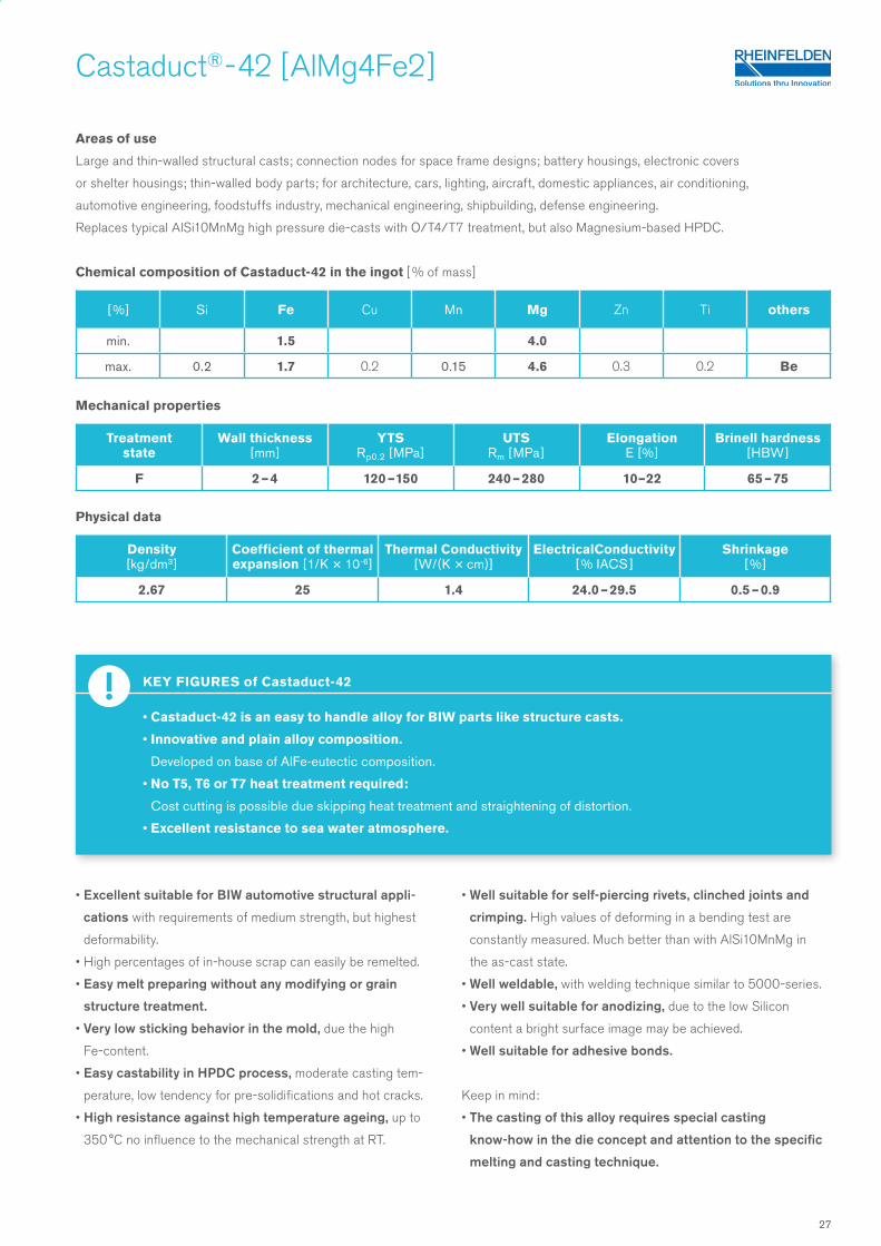
Castaduct® - 42 [ AlMg4Fe2 ]
[ %] Si Fe Cu Mn Mg Zn Ti others
min. 1.5 4.0
max. 0.2 1.7 0.2 0.15 4.6 0.3 0.2 Be
Treatment state
Wall thickness[mm ]
YTSRp0.2 [MPa ]
UTSRm [ MPa ]
ElongationE [ % ]
Brinell hardness[ HBW ]
F 2 – 4 120 – 150 240 – 280 10– 22 65 – 75
Density [ kg/dm3 ]
Coefficient of thermal expansion [ 1/K × 10-6]
Thermal Conductivity [W/(K × cm)]
ElectricalConductivity [ % IACS ]
Shrinkage [ % ]
2.67 25 1.4 24.0 – 29.5 0.5 – 0.9
27
100 µm 20 µm
Castaduct® - 42 [ AlMg4Fe2 ] – Properties
[ %] Si Fe Cu Mn Mg Zn Ti others
min. 1.5 4.0
max. 0.2 1.7 0.2 0.15 4.6 0.3 0.2 Be
Tab. 1: Chemical composition of Castaduct-42, AlMg4Fe2 in the ingot (in mass-%)
Chemical Composition
The Castaduct-42 high pressure die-casting alloy is simple and
robust in its alloy composition, based on the Al-Fe-Mg eutectic
in hypereutectic composition of the two alloying components
Fe and Mg. Iron is present in a necessary high content of about
1.6 %. The magnesium content is about 4.3 %.
For Castaduct-42, the Mg content should not fall below 4.0 %
and should not exceed 4.6 %. This is easy to handle at the
melting and casting plant because the Mg content need not be
precisely controlled and not set to tolerances of less than 0.05 %
by weight.
Also, a modification of the eutectic phases is omitted in this type
of alloy. The elimination of silicon as an alloying element elimi-
nates any Mg2Si precipitation hardening, i.e. the Castaduct-42
is naturally hard and has an excellent long-term stability even at
higher temperatures.
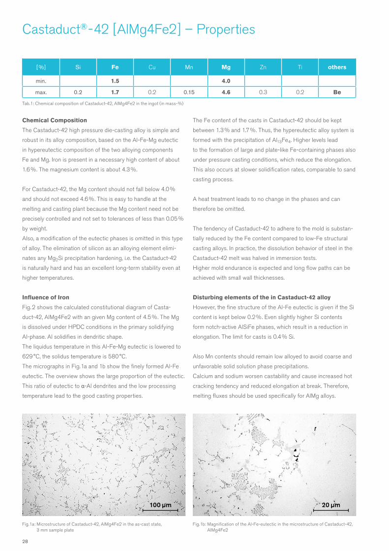
Influence of Iron
Fig. 2 shows the calculated constitutional diagram of Casta-
duct-42, AlMg4Fe2 with an given Mg content of 4.5 %. The Mg
is dissolved under HPDC conditions in the primary solidifying
Al-phase. Al solidifies in dendritic shape.
The liquidus temperature in this Al-Fe-Mg eutectic is lowered to
629 °C, the solidus temperature is 580 °C.
The micrographs in Fig. 1a and 1b show the finely formed Al-Fe
eutectic. The overview shows the large proportion of the eutectic.
This ratio of eutectic to α-Al dendrites and the low processing
temperature lead to the good casting properties.
The Fe content of the casts in Castaduct-42 should be kept
between 1.3 % and 1.7 %. Thus, the hypereutectic alloy system is
formed with the precipitation of Al13Fe4. Higher levels lead
to the formation of large and plate-like Fe-containing phases also
under pressure casting conditions, which reduce the elongation.
This also occurs at slower solidification rates, comparable to sand
casting process.
A heat treatment leads to no change in the phases and can
therefore be omitted.
The tendency of Castaduct-42 to adhere to the mold is substan-
tially reduced by the Fe content compared to low-Fe structural
casting alloys. In practice, the dissolution behavior of steel in the
Castaduct-42 melt was halved in immersion tests.
Higher mold endurance is expected and long flow paths can be
achieved with small wall thicknesses.
Disturbing elements of the in Castaduct-42 alloy
However, the fine structure of the Al-Fe eutectic is given if the Si
content is kept below 0.2 %. Even slightly higher Si contents
form notch-active AlSiFe phases, which result in a reduction in
elongation. The limit for casts is 0.4 % Si.
Also Mn contents should remain low alloyed to avoid coarse and
unfavorable solid solution phase precipitations.
Calcium and sodium worsen castability and cause increased hot
cracking tendency and reduced elongation at break. Therefore,
melting fluxes should be used specifically for AlMg alloys.
Fig. 1a: Microstructure of Castaduct-42, AlMg4Fe2 in the as-cast state, 3 mm sample plate
Fig. 1b: Magnification of the Al-Fe-eutectic in the microstructure of Castaduct-42, AlMg4Fe2
28
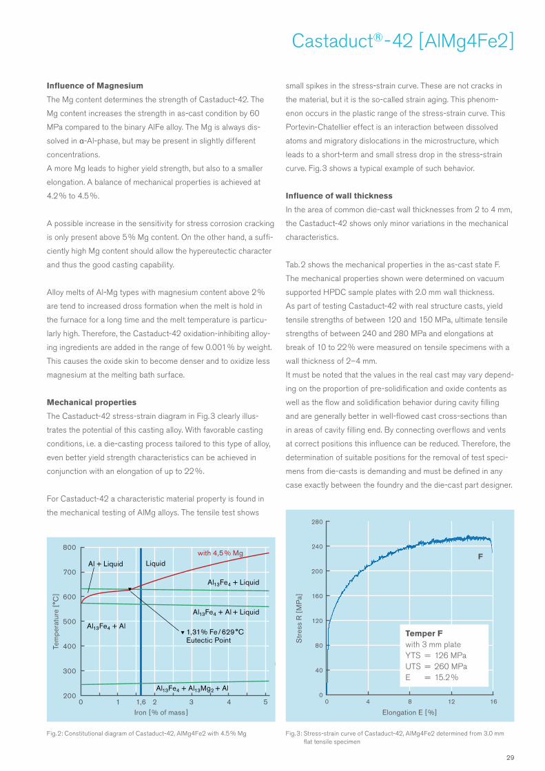
Fig. 3: Stress-strain curve of Castaduct-42, AlMg4Fe2 determined from 3.0 mm flat tensile specimen
Fig. 2: Constitutional diagram of Castaduct-42, AlMg4Fe2 with 4.5 % Mg
Elongation E [ %]
Str
ess
R [
MP
a]
F
0 4 8 12 16
280
240
200
160
120
80
40
0
Temper Fwith 3 mm plateYTS = 126 MPaUTS = 260 MPaE = 15.2 %
Castaduct® - 42 [ AlMg4Fe2 ]
Influence of Magnesium
The Mg content determines the strength of Castaduct-42. The
Mg content increases the strength in as-cast condition by 60
MPa compared to the binary AlFe alloy. The Mg is always dis-
solved in α-Al-phase, but may be present in slightly different
concentrations.
A more Mg leads to higher yield strength, but also to a smaller
elongation. A balance of mechanical properties is achieved at
4.2 % to 4.5 %.
A possible increase in the sensitivity for stress corrosion cracking
is only present above 5 % Mg content. On the other hand, a suffi-
ciently high Mg content should allow the hypereutectic character
and thus the good casting capability.
Alloy melts of Al-Mg types with magnesium content above 2 %
are tend to increased dross formation when the melt is hold in
the furnace for a long time and the melt temperature is particu-
larly high. Therefore, the Castaduct-42 oxidation-inhibiting alloy-
ing ingredients are added in the range of few 0.001 % by weight.
This causes the oxide skin to become denser and to oxidize less
magnesium at the melting bath surface.
Mechanical properties
The Castaduct-42 stress-strain diagram in Fig. 3 clearly illus-
trates the potential of this casting alloy. With favorable casting
conditions, i.e. a die-casting process tailored to this type of alloy,
even better yield strength characteristics can be achieved in
conjunction with an elongation of up to 22 %.
For Castaduct-42 a characteristic material property is found in
the mechanical testing of AlMg alloys. The tensile test shows
small spikes in the stress-strain curve. These are not cracks in
the material, but it is the so-called strain aging. This phenom-
enon occurs in the plastic range of the stress-strain curve. This
Portevin-Chatellier effect is an interaction between dissolved
atoms and migratory dislocations in the microstructure, which
leads to a short-term and small stress drop in the stress-strain
curve. Fig. 3 shows a typical example of such behavior.
Influence of wall thickness
In the area of common die-cast wall thicknesses from 2 to 4 mm,
the Castaduct-42 shows only minor variations in the mechanical
characteristics.
Tab. 2 shows the mechanical properties in the as-cast state F.
The mechanical properties shown were determined on vacuum
supported HPDC sample plates with 2.0 mm wall thickness.
As part of testing Castaduct-42 with real structure casts, yield
tensile strengths of between 120 and 150 MPa, ultimate tensile
strengths of between 240 and 280 MPa and elongations at
break of 10 to 22 % were measured on tensile specimens with a
wall thickness of 2–4 mm.
It must be noted that the values in the real cast may vary depend-
ing on the proportion of pre-solidification and oxide contents as
well as the flow and solidification behavior during cavity filling
and are generally better in well-flowed cast cross-sections than
in areas of cavity filling end. By connecting overflows and vents
at correct positions this influence can be reduced. Therefore, the
determination of suitable positions for the removal of test speci-
mens from die-casts is demanding and must be defined in any
case exactly between the foundry and the die-cast part designer.
Iron [ % of mass ]
Tem
pera
ture
[°C
]
0 1 1,6 2 3 4 5
800
700
600
500
400
300
200Al13Fe4 + Al13Mg2 + Al
Al13Fe4 + Al + Liquid
1,31 % Fe / 629 °C Eutectic Point
Al13Fe4 + Liquid
Liquidwith 4,5 % Mg
Al13Fe4 + Al
Al + Liquid
29

1,574 mm
0,837 mm 0,398 mm 0,311 mm
1,841 mm
Castaduct® - 42 [ AlMg4Fe2 ] – Properties
Deformation capability
The Castaduct-42 alloy has a very high deformability in as-cast
condition and is thus also well suited for crash-relevant applica-
tions in vehicle design. The evidence was provided in the context
of alloy development by means of plate bending test for metallic
materials, according to VDA 238 – 100 (Fig. 4) and with Erichsen
cupping tests and confirmed several times by samples of real
casts. Plate bending angles of up to 60 ° are achieved. Bending
angles of more than 70 ° could be achieved with proper casting
conditions. These high measurement values indicate a very good
behavior in punch riveting and similar joining methods.
The Erichsen cupping test is another test for the suitability of a
casting alloy for structural components in vehicle design. Here,
a sheet-like test strip from the cast is deliberately deformed to a
point of first fissure by a ball lowering in the measurement setup.
With increasing sample plate thickness the Erichsen depression
decreases. For a 2.0 mm sample plate in AlSi alloy deformation
values around 3 mm are common. For the same sample plate in
Castaduct-42 the values of 4.5 mm are very high and indicate a
high deformation capacity in the event of a crash.
In the context of alloy development, a hudge amount of punching
tests were carried out with very good results on 3.0 mm sample
plates and on samples of real Castaduct-42 casts (Fig. 5a/5b).
Castaduct-42 was always tested in as-cast condition and showed
very good results.
Welding performance
In addition to the very good punch riveting ability, a good degree
of welding suitability is of great importance for the use of Casta-
duct-42 in vehicle design.
In the MIG process, Castaduct-42 die-cast sample plates 3.0 mm
were butt-welded and fillet-welded to AW-AlMgSi0.5 to test the
weldability (Fig. 6a/6b). The welding filler material used was an
S - AlMg4.5Mn welding wire with Ø 1.2 mm.
The micrographs of the welded seams show a low-pore and finely
structured microstructure, which results in homogeneous material
properties in the joining zone. The silicon free welding conditions
leads here to no significant changes in the mechanical character-
istics. The right choice of welding filler material leads to crack-
free and ductile welds.
For welded joints on aluminum sheets of the 6000 series, i.e.
AlMgSi alloys, the alloy S - AlMg4.5Mn is also recommended as
the welding filler material.
Distance [mm]
Forc
e [N
]
Fig. 4: Load-extension diagram of plate bending test Castaduct-42 , AlMg4Fe2 Fig. 5b: Crossection with calculation of the HSN rivet test in Castaduct-42, AlMg4Fe2
Fig. 5a: Rivet tests connecting steel sheet to HPDC in Castaduct-42, AlMg4Fe2
0 2 4 6 8
4000
3500
3000
2500
2000
1500
1000
500
0
Bending testwith 2 mm platefollowing VDA 238 – 100distance = 6.86 mmAngle α = 56.7 °
Tab 2: Mechanical properties of Castaduct-42, AlMg4Fe2 in the as-cast state; the typical wall thickness of the several tested HPDC are 2–4 mm
Treatment state
Wall thickness[mm ]
YTSRp0.2 [MPa ]
UTSRm [ MPa ]
ElongationE [ % ]
Brinell hardness[ HBW ]
F 2 – 4 120 – 150 240 – 280 10– 22 65 – 75
30
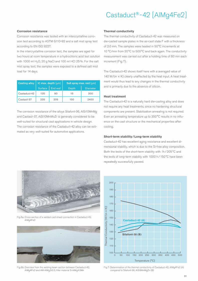
Castaduct® - 42 [ AlMg4Fe2 ]
Corrosion resistance
Corrosion resistance was tested with an intercrystalline corro-
sion test according to ASTM G110-92 and a salt mist spray test
according to EN ISO 9227.
In the intercrystalline corrosion test, the samples are aged for
two hours at room temperature in a hydrochloric acid test solution
with 1000 ml H2O, 20 g NaCl and 100 ml HCl 25 %. For the salt
mist spray test, the samples were exposed to a defined salt mist
load for 14 days.
The corrosion resistance of the alloys Silafont-36, AlSi10MnMg
and Castasil-37, AlSi10MnMoZr is generally considered to be
well-suited for structural cast applications in vehicle design.
The corrosion resistance of the Castaduct-42 alloy can be esti-
mated as very well-suited for automotive applications.
Thermal conductivity
The thermal conductivity of Castaduct-42 was measured on
die-casted sample plates in the as-cast state F with a thickness
of 2.0 mm. The samples were heated in 50 °C increments at
10 °C /min from 20 °C to 500 °C and back again. The conductivity
measurement was carried out after a holding time of 60 min each
increment (Fig. 7).
The Castaduct-42 shows itself here with a averaged value of
140 W/(m × K) clearly unaffected by the heat input. A heat treat-
ment would thus lead to any changes in the thermal conductivity
and is primarily due to the absence of silicon.
Heat treatment
The Castaduct-42 is a naturally hard die-casting alloy and does
not require any heat treatments, since no hardening structural
components are present. Stabilization annealing is not required.
Even an annealing temperature up to 350 °C results in no influ-
ence on the cast structure or the mechanical properties after
cooling.
Short-term stability / Long-term stability
Castaduct-42 has excellent aging resistance and excellent di-
mensional stability, which is due to the Si-free alloy composition.
Both the tests of the short-term stability with 1h / 205 °C and
the tests of long-term stability with 1000 h / 150 °C have been
repeatedly successfully passed.
Fig. 6a: Cross-section of a welded cast-sheet-connection in Castaduct-42, AlMg4Fe2
Fig. 6b: Overview from the welding beam section between Castaduct-42, AlMg4Fe2 and AW-AlMgSi0.5; filler material S - AlMg4.5Mn
Fig. 7: Determination of the thermal conductivity of Castaduct-42, AlMg4Fe2 (A) compared to Silafont-38, AlSi9MnMgZn (B)
Temperature [°C]
Ther
mal
Con
duct
ivity
[W
/(m
× K
)]
0 50 100 150 200 250 300 350 400 450 500
200
190
180
170
160
150
140
130
120
110
100
Castaduct-42 (A)
Casting alloy IC max. depth [µm] Salt spray max. raid [µm]
Surface End wall Depth Diameter
Castaduct-42 135 90 15 200
Castasil-37 235 205 150 2400
Silafont-38 (B)
31
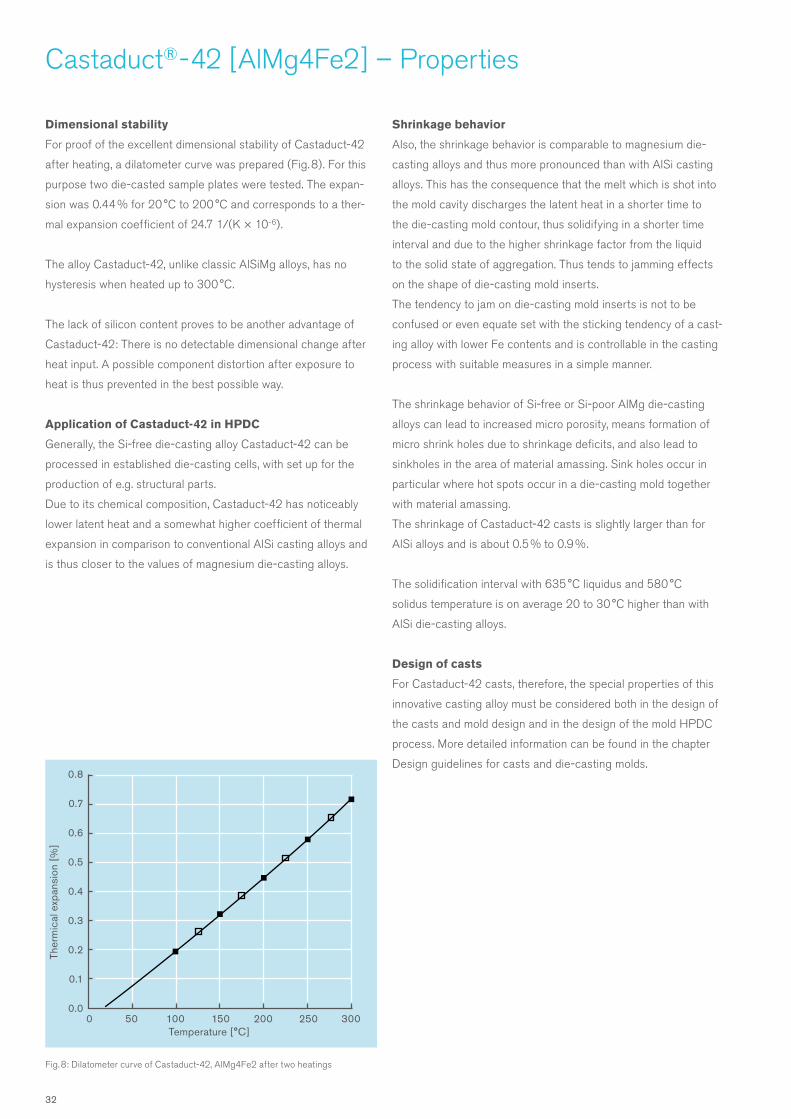
Castaduct® - 42 [ AlMg4Fe2 ] – Properties
Dimensional stability
For proof of the excellent dimensional stability of Castaduct-42
after heating, a dilatometer curve was prepared (Fig. 8). For this
purpose two die-casted sample plates were tested. The expan-
sion was 0.44 % for 20 °C to 200 °C and corresponds to a ther-
mal expansion coefficient of 24.7 1/(K × 10-6).
The alloy Castaduct-42, unlike classic AlSiMg alloys, has no
hysteresis when heated up to 300 °C.
The lack of silicon content proves to be another advantage of
Castaduct-42: There is no detectable dimensional change after
heat input. A possible component distortion after exposure to
heat is thus prevented in the best possible way.
Application of Castaduct-42 in HPDC
Generally, the Si-free die-casting alloy Castaduct-42 can be
processed in established die-casting cells, with set up for the
production of e.g. structural parts.
Due to its chemical composition, Castaduct-42 has noticeably
lower latent heat and a somewhat higher coefficient of thermal
expansion in comparison to conventional AlSi casting alloys and
is thus closer to the values of magnesium die-casting alloys.
Shrinkage behavior
Also, the shrinkage behavior is comparable to magnesium die-
casting alloys and thus more pronounced than with AlSi casting
alloys. This has the consequence that the melt which is shot into
the mold cavity discharges the latent heat in a shorter time to
the die-casting mold contour, thus solidifying in a shorter time
interval and due to the higher shrinkage factor from the liquid
to the solid state of aggregation. Thus tends to jamming effects
on the shape of die-casting mold inserts.
The tendency to jam on die-casting mold inserts is not to be
confused or even equate set with the sticking tendency of a cast-
ing alloy with lower Fe contents and is controllable in the casting
process with suitable measures in a simple manner.
The shrinkage behavior of Si-free or Si-poor AlMg die-casting
alloys can lead to increased micro porosity, means formation of
micro shrink holes due to shrinkage deficits, and also lead to
sinkholes in the area of material amassing. Sink holes occur in
particular where hot spots occur in a die-casting mold together
with material amassing.
The shrinkage of Castaduct-42 casts is slightly larger than for
AlSi alloys and is about 0.5 % to 0.9 %.
The solidification interval with 635 °C liquidus and 580 °C
solidus temperature is on average 20 to 30 °C higher than with
AlSi die-casting alloys.
Design of casts
For Castaduct-42 casts, therefore, the special properties of this
innovative casting alloy must be considered both in the design of
the casts and mold design and in the design of the mold HPDC
process. More detailed information can be found in the chapter
Design guidelines for casts and die-casting molds.
Fig. 8: Dilatometer curve of Castaduct-42, AlMg4Fe2 after two heatings
Temperature [°C]
Ther
mic
al e
xpan
sion
[%
]
0 50 100 150 200 250 300
0.8
0.7
0.6
0.5
0.4
0.3
0.2
0.1
0.0
32

Castaduct® - 42 [ AlMg4Fe2 ]
Melt process
The Castaduct-42 is an AlMg-type alloy with high Fe content
and must not be contaminated with Si or Mn. A microstructural
modification as required with AlSi structural casting alloys is
not required. The tendency to oxidation on the surface of the
melt bath is considerably reduced by a low content of oxidation-
inhibiting alloying ingredients. Agglomerations of oxides on bath
surfaces and on the bottom of the furnace barely form.
After rapid melting of the ingots a melt cleaning with a gas rotor
have to be carried out. The properties of Castaduct-42 are re-
tained if no sodium-containing treatment fluxes, no grain refining
or modification, no phosphorus, alkali and earth alkali containing
substances and no different metals are supplied to the melt.
The temperature during melting should not permanently exceed
780 °C. The holding temperature after melting should be set
to 760 °C (Fig. 9).
In melting furnaces, which keep the melt moving with heat con-
vection, the form of lids are reduced by less oxide-melt reactions
and segregations. This also applies to furnaces in which the bath
movement takes place by means of rotor or purge gas initiation
by furnace bottom stones.
Furnaces with roof heating and no bath movement cause difficul-
ties for longer holding time without additional refilling due to the
production with AlMg alloys.
Melting of all aluminum alloys and also Castaduct-42 reacts
less with the refractory material, if it contains more than 85 %
aluminum oxide.
The remelting of runners, return scrap and others is not a prob-
lem. However, care must be taken that mixing with other alloys
cannot take place. In particular, an increase in the silicon content
has a negative effect on the mechanical properties.
When using return material, a good melt cleaning by means of
rotor and argon or nitrogen gas is absolutely necessary, since
oxide inclusions, oxide skins, etc. have to be removed. These
can accumulate in the melting and casting process and exert a
negative influence on the component properties.
The resulting dross after cleaning and degassing cycle can
be reduced in their metal content with use of sodium-free
treatment flux.
Casting process
The quality of the cast, with regard to the mechanical charac-
teristics, the ability to deform and the weldability, is primarily
determined by the proportion of oxides and other impurities in
the melt and by the gases entrapped in the casts.
These may be due to the H2 content of the melt, residual air
in the die-casting mold cavity, release agent residues, casting
piston lubricants and residuals of moisture.
Already the melt handling in the foundry can have a big influence
on the quality of the casts. A high melt temperature can lead
to increased oxidation of the melt, which on the other hand leads
to higher oxide and hydrogen levels.
Fig 9: Typical temperature losses in melt handling during casting process; here with Castaduct-42, AlMg4Fe2
740 °C
760 °C
Metal in the HPDC chamber
Holding furnaceDosing
Transport
Melt cleaningImpeller
Melting
720 °C
680 °C
720 °C
740 °C
690 °C
650 °C
730 °C
700 °C
33
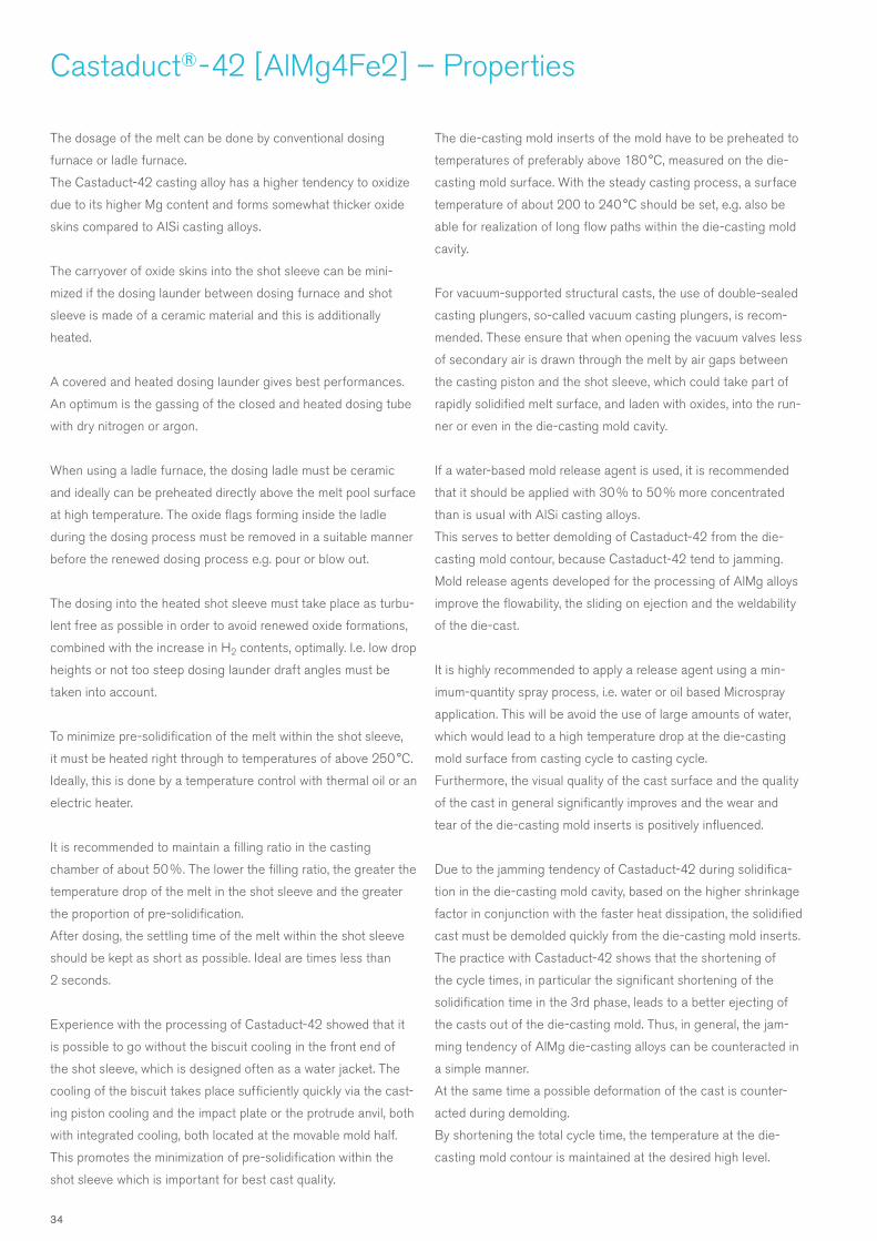
Castaduct® - 42 [ AlMg4Fe2 ] – Properties
The dosage of the melt can be done by conventional dosing
furnace or ladle furnace.
The Castaduct-42 casting alloy has a higher tendency to oxidize
due to its higher Mg content and forms somewhat thicker oxide
skins compared to AlSi casting alloys.
The carryover of oxide skins into the shot sleeve can be mini-
mized if the dosing launder between dosing furnace and shot
sleeve is made of a ceramic material and this is additionally
heated.
A covered and heated dosing launder gives best performances.
An optimum is the gassing of the closed and heated dosing tube
with dry nitrogen or argon.
When using a ladle furnace, the dosing ladle must be ceramic
and ideally can be preheated directly above the melt pool surface
at high temperature. The oxide flags forming inside the ladle
during the dosing process must be removed in a suitable manner
before the renewed dosing process e.g. pour or blow out.
The dosing into the heated shot sleeve must take place as turbu-
lent free as possible in order to avoid renewed oxide formations,
combined with the increase in H2 contents, optimally. I.e. low drop
heights or not too steep dosing launder draft angles must be
taken into account.
To minimize pre-solidification of the melt within the shot sleeve,
it must be heated right through to temperatures of above 250 °C.
Ideally, this is done by a temperature control with thermal oil or an
electric heater.
It is recommended to maintain a filling ratio in the casting
chamber of about 50 %. The lower the filling ratio, the greater the
temperature drop of the melt in the shot sleeve and the greater
the proportion of pre-solidification.
After dosing, the settling time of the melt within the shot sleeve
should be kept as short as possible. Ideal are times less than
2 seconds.
Experience with the processing of Castaduct-42 showed that it
is possible to go without the biscuit cooling in the front end of
the shot sleeve, which is designed often as a water jacket. The
cooling of the biscuit takes place sufficiently quickly via the cast-
ing piston cooling and the impact plate or the protrude anvil, both
with integrated cooling, both located at the movable mold half.
This promotes the minimization of pre-solidification within the
shot sleeve which is important for best cast quality.
The die-casting mold inserts of the mold have to be preheated to
temperatures of preferably above 180 °C, measured on the die-
casting mold surface. With the steady casting process, a surface
temperature of about 200 to 240 °C should be set, e.g. also be
able for realization of long flow paths within the die-casting mold
cavity.
For vacuum-supported structural casts, the use of double-sealed
casting plungers, so-called vacuum casting plungers, is recom-
mended. These ensure that when opening the vacuum valves less
of secondary air is drawn through the melt by air gaps between
the casting piston and the shot sleeve, which could take part of
rapidly solidified melt surface, and laden with oxides, into the run-
ner or even in the die-casting mold cavity.
If a water-based mold release agent is used, it is recommended
that it should be applied with 30 % to 50 % more concentrated
than is usual with AlSi casting alloys.
This serves to better demolding of Castaduct-42 from the die-
casting mold contour, because Castaduct-42 tend to jamming.
Mold release agents developed for the processing of AlMg alloys
improve the flowability, the sliding on ejection and the weldability
of the die-cast.
It is highly recommended to apply a release agent using a min-
imum-quantity spray process, i.e. water or oil based Microspray
application. This will be avoid the use of large amounts of water,
which would lead to a high temperature drop at the die-casting
mold surface from casting cycle to casting cycle.
Furthermore, the visual quality of the cast surface and the quality
of the cast in general significantly improves and the wear and
tear of the die-casting mold inserts is positively influenced.
Due to the jamming tendency of Castaduct-42 during solidifica-
tion in the die-casting mold cavity, based on the higher shrinkage
factor in conjunction with the faster heat dissipation, the solidified
cast must be demolded quickly from the die-casting mold inserts.
The practice with Castaduct-42 shows that the shortening of
the cycle times, in particular the significant shortening of the
solidification time in the 3rd phase, leads to a better ejecting of
the casts out of the die-casting mold. Thus, in general, the jam-
ming tendency of AlMg die-casting alloys can be counteracted in
a simple manner.
At the same time a possible deformation of the cast is counter-
acted during demolding.
By shortening the total cycle time, the temperature at the die-
casting mold contour is maintained at the desired high level.
34

Castaduct® - 42 [ AlMg4Fe2 ]
HPDC start and die-casting cycle
Due to the jamming tendency also the initial casts must be com-
pletely poured on the die-casting machine.
Casting at too low shot speed will not ensure the integrity of the
cast and a safely demold of the cast is not possible. The ejector
pins may pierce through the unfinished cast.
It is recommended to pour the initial casts with at least 70 % of
the plunger speed selected for the series process. Furthermore, it
is necessary to avoid any termination of the started 2nd phase in
the course of the HPDC cycle.
As part of testing the Castaduct-42 in existing AlSi die-casting
molds, the solidification times could be reduced down to the
single-digit seconds range!
The total cycle times in the die-casting process could be reduced
by one- or two-digit seconds using the Castaduct-42 die-casting
alloy!
Trimming process
The Castaduct-42 casts can be cooled directly from the casting
heat in a water bath or in air. The type of cooling has no notice-
able influence on the material properties of the finished cast.
For ductile die-casting alloys it is recommended to use a cutting
blade designed with a sloping surface, so that the ingate section,
runners, burrs, overflows and venting channels are cut off with
less force. Flat-faced punching blades squeeze with greater ef-
fort from the ingate section, with the risk of break-outs may exist.
When using cutting blades that are sloped with an angle of
approx. 3° to 5°, the required stroke for the deburring cut only
increases minimally.
The trials in the context of alloy development showed that after
demolding the cast from the die-casting mold, the shrinkage
of the solid is only slightly greater than with casts made of AlSi
casting alloys: The casts made with Castaduct-42 were punched
on a trimming tool without damage, even if designed for trimming
of AlSi casts.
Case Study
The sample cast was a structural casting with 910 mm length,
510 mm width and 6.5 kg part weight, with Castaduct-42 alloy
in a die-casting cell designed for AlSi10MnMg applications. The
shot weight was about 11 kg.
The wall thickness was over the flow path length of 850 mm in
the region of the ingate 3.5 mm and in the back wall 2.5 mm.
The Castaduct-42 was stored and kept warm in a conventional,
closed dosing furnace at 710 °C, later in the course of the trial
at 690 °C.
The temperature level of the die-casting mold was raised to
above 200 °C. As a result, the die-casting mold temperature was
on average 50 °C higher than that with AlSi alloys.
Significant is the reduction of the solidification time until ejection
in the context of the trial of originally 16 seconds to 10 seconds.
The biscuit cooling at the front end of the casting chamber was
switched off.
The plunger speed for the die-casting shot was set for a cavity
filling time of 49 ms, which made possible by the higher die-
casting mold temperature.
For the startup of the HPDC trial the release agent to water ratio
was increased for a more rich mixture from 1:100 for AlSi alloys
to 1:50 for AlMg alloys.
A total of about 175 shots were poured, of which 130 shots
continuously without any interruptions. Overall, the casting result
was classified as very good. The mold filling capacity is pleas-
ingly good. The casts could be poured cleanly without signs of
cold flow, hot cracks or pulling marks. The die-casting mold itself
showed no adhesions or soldering in the area of the hollow cavity,
which would have led to pulling marks. All Castaduct-42 casts
were trimmed hand-hot without problems with the standard
trimming tool by use of the automatic sequence in the die-casting
cell.
The measured mechanical properties for yield strength (Rp0.2),
tensile strength (Rm) and elongation (E) from Castaduct-42
structural in as-cast condition were better at yield strength and
elongation when compared to alloy AlSi10MnMg plus annealing
treatment to the state O.
Mechanical properties of HPDC trials with Castaduct-42, AlMg4Fe2
In critical cast areas with strongly turbulent filling, individual lower
values for the elongation at break were measured analogously to
the alloy AlSi10MnMg at annealing state O.
Rp0.2 (YTS)[ MPa ]
Rm (UTS)[ MPa ]
A (E)[ % ]
Structural cast 120 – 137 241 – 268 7.5 – 17.6
average 129 250 11.4
35
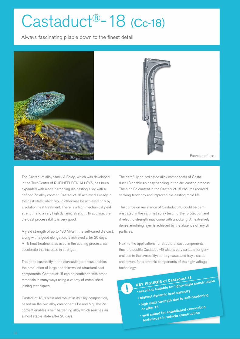
Castaduct®- 18 (Cc-18)Always fascinating pliable down to the finest detail
The Castaduct alloy family AlFeMg, which was developed
in the TechCenter of RHEINFELDEN ALLOYS, has been
expanded with a self-hardening die casting alloy with a
defined Zn alloy content. Castaduct-18 achieved already in
the cast state, which would otherwise be achieved only by
a solution heat treatment. There is a high mechanical yield
strength and a very high dynamic strength. In addition, the
die-cast processability is very good.
A yield strength of up to 180 MPa in the self-cured die cast,
along with a good elongation, is achieved after 20 days.
A T5 heat treatment, as used in the coating process, can
accelerate this increase in strength.
The good castability in the die-casting process enables
the production of large and thin-walled structural cast
components. Castaduct-18 can be combined with other
materials in many ways using a variety of established
joining techniques.
Castaduct-18 is plain and robust in its alloy composition,
based on the two alloy components Fe and Mg. The Zn-
content enables a self-hardening alloy which reaches an
almost stable state after 20 days.
The carefully co-ordinated alloy components of Casta-
duct-18 enable an easy handling in the die-casting process.
The high Fe content in the Castaduct-18 ensures reduced
sticking tendency and improved die-casting mold life.
The corrosion resistance of Castaduct-18 could be dem-
onstrated in the salt mist spray test. Further protection and
di-electric strength may come with anodizing. An extremely
dense anodizing layer is achieved by the absence of any Si
particles.
Next to the applications for structural cast components,
thus the ductile Castaduct-18 also is very suitable for gen-
eral use in the e-mobility: battery cases and trays, cases
and covers for electronic components of the high-voltage
technology.
KEY FIGURES of Castaduct-18
• excellent suitable for lightweight construction
• highest dynamic load capacity
• high yield strength due to self-hardening
or after T5
• well suited for established connection
techniques in vehicle construction
Example of use
36
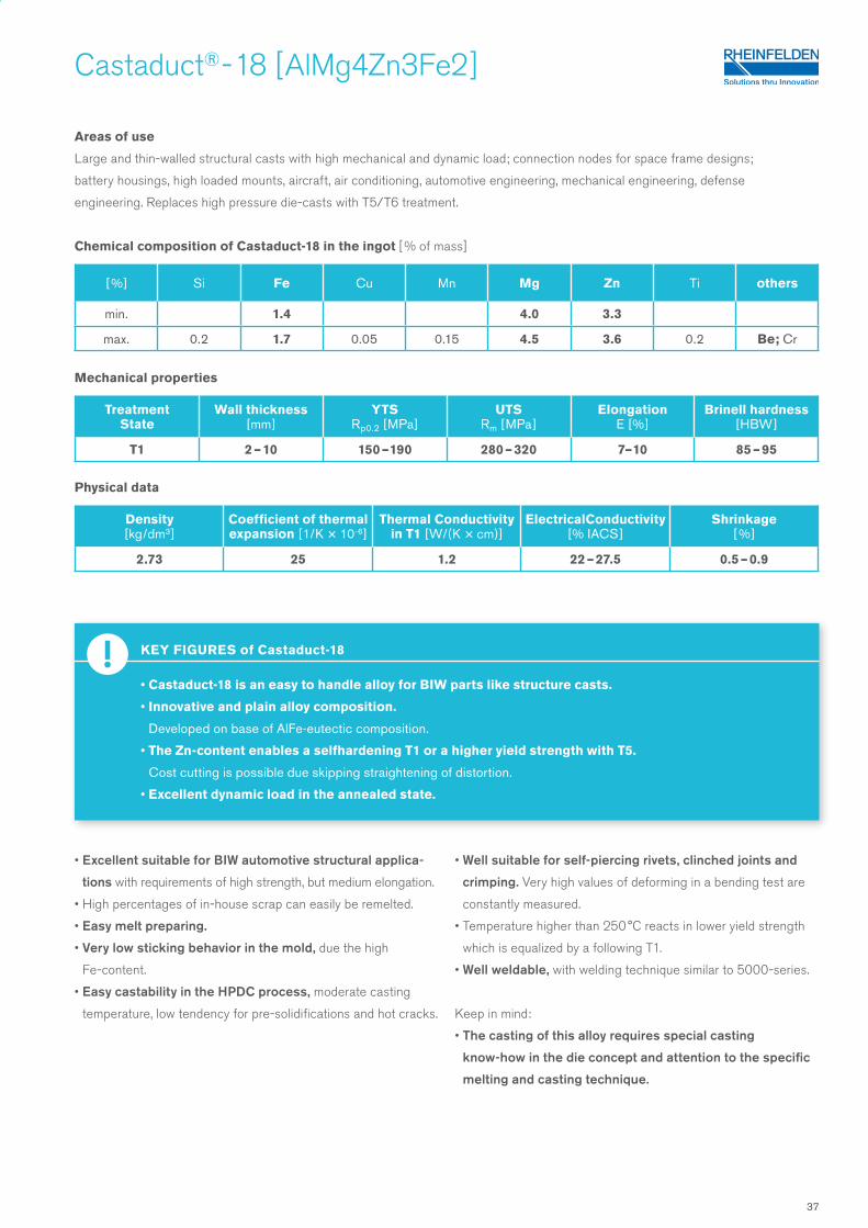
KEY FIGURES of Castaduct-18
• Castaduct-18 is an easy to handle alloy for BIW parts like structure casts.
• Innovative and plain alloy composition.
Developed on base of AlFe-eutectic composition.
• The Zn-content enables a selfhardening T1 or a higher yield strength with T5.
Cost cutting is possible due skipping straightening of distortion.
• Excellent dynamic load in the annealed state.
Areas of use
Large and thin-walled structural casts with high mechanical and dynamic load; connection nodes for space frame designs;
battery housings, high loaded mounts, aircraft, air conditioning, automotive engineering, mechanical engineering, defense
engineering. Replaces high pressure die-casts with T5/T6 treatment.
Chemical composition of Castaduct-18 in the ingot [ % of mass]
Mechanical properties
Physical data
• Excellent suitable for BIW automotive structural applica-
tions with requirements of high strength, but medium elongation.
• High percentages of in-house scrap can easily be remelted.
• Easy melt preparing.
• Very low sticking behavior in the mold, due the high
Fe-content.
• Easy castability in the HPDC process, moderate casting
temperature, low tendency for pre-solidifications and hot cracks.
• Well suitable for self-piercing rivets, clinched joints and
crimping. Very high values of deforming in a bending test are
constantly measured.
• Temperature higher than 250 °C reacts in lower yield strength
which is equalized by a following T1.
• Well weldable, with welding technique similar to 5000-series.
Keep in mind:
• The casting of this alloy requires special casting
know-how in the die concept and attention to the specific
melting and casting technique.
Castaduct® - 18 [ AlMg4Zn3Fe2 ]
[ %] Si Fe Cu Mn Mg Zn Ti others
min. 1.4 4.0 3.3
max. 0.2 1.7 0.05 0.15 4.5 3.6 0.2 Be; Cr
Treatment State
Wall thickness[mm ]
YTSRp0.2 [MPa ]
UTSRm [ MPa ]
ElongationE [ % ]
Brinell hardness[ HBW ]
T1 2 – 10 150 – 190 280 – 320 7– 10 85 – 95
Density [ kg/dm3 ]
Coefficient of thermal expansion [ 1/K × 10-6]
Thermal Conductivity in T1 [W/(K × cm)]
ElectricalConductivity [% IACS ]
Shrinkage [ % ]
2.73 25 1.2 22 – 27.5 0.5 – 0.9
37
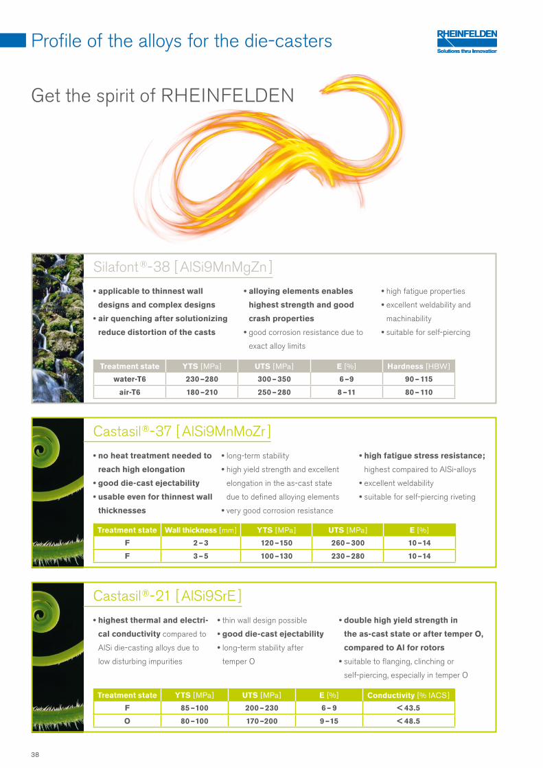
Get the spirit of RHEINFELDEN
Profile of the alloys for the die-casters
• no heat treatment needed to
reach high elongation
• good die-cast ejectability
• usable even for thinnest wall
thicknesses
• highest thermal and electri-
cal conductivity compared to
AlSi die-casting alloys due to
low disturbing impurities
Castasil ®- 21 [ AlSi9SrE ]
• long-term stability
• high yield strength and excellent
elongation in the as-cast state
due to defined alloying elements
• very good corrosion resistance
• thin wall design possible
• good die-cast ejectability
• long-term stability after
temper O
• high fatigue stress resistance;
highest compaired to AlSi-alloys
• excellent weldability
• suitable for self-piercing riveting
• double high yield strength in
the as-cast state or after temper O,
compared to Al for rotors
• suitable to flanging, clinching or
self-piercing, especially in temper O
Castasil ®- 37 [ AlSi9MnMoZr ]
Treatment state YTS [ MPa ] UTS [ MPa ] E [ % ] Conductivity [ % IACS ]
F 85 – 100 200 – 230 6 – 9 < 43.5
O 80 – 100 170 –200 9 – 15 < 48.5
Treatment state Wall thickness [ mm ] YTS [ MPa ] UTS [ MPa ] E [ % ]
F 2 – 3 120 – 150 260 – 300 10 – 14
F 3 – 5 100 – 130 230 – 280 10 – 14
Silafont ®- 38 [ AlSi9MnMgZn ]
• applicable to thinnest wall
designs and complex designs
• air quenching after solutionizing
reduce distortion of the casts
• alloying elements enables
highest strength and good
crash properties
• good corrosion resistance due to
exact alloy limits
• high fatigue properties
• excellent weldability and
machinability
• suitable for self-piercing
Treatment state YTS [ MPa ] UTS [ MPa ] E [ % ] Hardness [ HBW ]
water-T6 230 – 280 300 – 350 6 – 9 90 – 115
air-T6 180 – 210 250 – 280 8 – 11 80 – 110
38
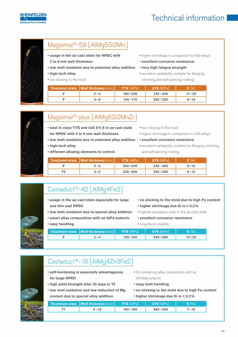
Technical information
Magsimal ®- plus [ AlMg6Si2MnZr ]
Magsimal ®- 59 [ AlMg5Si2Mn ]
• best in class YTS and still 8 % E in as-cast state
for HPDC with 2 to 6 mm wall thickness
• low melt oxidation due to patented alloy addition
• high-tech alloy
• different alloying elements to control
• usage in the as-cast state for HPDC with
2 to 8 mm wall thickness
• low melt oxidation due to patented alloy addition
• high-tech alloy
• low sticking to the mold
• low sticking to the mold
• higher shrinkage in comparison to AlSi-alloys
• excellent corrosion resistance
• excellent weldability, suitable for flanging, clinching
and self-piercing riveting
• higher shrinkage in comparison to AlSi-alloys
• excellent corrosion resistance
• very high fatigue strength
• excellent weldability, suitable for flanging,
clinching and self-piercing riveting
Treatment state Wall thickness [ mm ] YTS [ MPa ] UTS [ MPa ] E [ % ]
F 2 – 4 160 – 220 310 – 340 11 – 22
F 4 – 6 140 – 170 250 – 320 9 – 14
Castaduct ®- 42 [ AlMg4Fe2 ]
Castaduct ®- 18 [ AlMg4Zn3Fe2 ]
• usage in the as-cast state especially for large
and thin wall HPDC
• low melt oxidation due to special alloy addition
• smart alloy composition with an AlFe eutectic
• easy handling
• self-hardening is especially advantageous
for large HPDC
• high yield strength after 20 days or T5
• low melt oxidation and low reduction of Mg
content due to special alloy addition
• no sticking to the mold due to high Fe content
• higher shrinkage due Si is < 0.2 %
• highest elongation even in the as-cast state
• excellent corrosion resistance
• long therm stability
• Zn-containing alloy composition with an
AlFeMg eutectic
• easy melt handling
• no sticking to the mold due to high Fe content
• higher shrinkage due Si is < 0.2 %
Treatment state Wall thickness [ mm ] YTS [ MPa ] UTS [ MPa ] E [ % ]
F 2 – 4 120 – 150 240 – 280 10 – 22
Treatment state Wall thickness [ mm ] YTS [ MPa ] UTS [ MPa ] E [ % ]
T1 2 – 10 150 – 190 280 – 320 7 – 10
Treatment state Wall thickness [ mm ] YTS [ MPa ] UTS [ MPa ] E [ % ]
F 2 –3 200 – 220 340 – 360 9 – 12
T5 2 –3 230 – 250 350 – 380 8 – 12
39
1 Reinigung
2 Einschmelzen der Masseln
3 Salzbehandlung
4 Strontiumabbrand
5 Abkrätzen
6 Temperatur nach dem Einschmelzen und im
Warmhalteofen 7 Entgasen und Reinigen
der Schmelze
8 Abkrätzen
9 Gießtemperatur ( Richtwerte )
10 Formtemperatur
11 Gießwerkzeug- und Gießkammer-Temperatur
Castasil ®- 37 [ AlSi9MnMoZr ]
Arbeitsfolge bei der Herstellung von Druckgussstücken aus Castasil-37 Öfen, Tiegel, Behandlungs- und Gießwerkzeuge reinigen, um Verunreinigungen mit
unerwünschten Elementen wie Cu, Zn und insbesondere Mg zu vermeiden !
Die Schmelze sollte zügig über 670 °C gebracht werden, um Seigerungen, z. B. des
Mn-haltigen Mischkristalles in der Schmelze zu vermeiden. Die Schmelzetemperatur
sollte 780 °C nicht übersteigen. Ein Abbrand von Sr beim Schmelzen und Warm-
halten ist zu erwarten – und umso stärker, je höher die Temperatur ist. Besonders
beim Einschmelzen von Kreislaufmaterial ist der Sr-Abbrand zu beachten und eine
Entgasungsbehandlung zum Entfernen von H2 und Oxiden empfohlen. Mit zuneh-
mendem Sr-Gehalt steigt die Neigung der Schmelze Wasserstoff aufzunehmen;
daher sollte dieser nicht über 350 ppm liegen.
beim Schmelzen nicht nötigüblicherweise Abbrand von 30 – 50 ppm je Schmelzung; Sr ist nur aufzulegieren,
wenn der Gehalt in der Schmelze unterhalb von 60 ppm liegt, mit AlSr5 oder AlSr10.
Bei erstmaligem Aufschmelzen in einem neuen Tiegel oder einem Tiegel, der
bisher nicht für Sr-veredelte Legierungen verwendet wurde, fällt der Sr-Gehalt stark
ab. Dabei diffundiert Strontium in den Tiegel; eine Sättigung ist nach erstem Auf-
schmelzen erreicht.
nach dem Einschmelzen erforderlich; kalte Werkzeuge führen, neben ihrem
Gefährdungspotenzial, eventuell zur Seigerung von Molybdän.
Dauertemperatur: maximal 780 °C ( Temperatur kontrollieren ! ); nicht unter 680 °C
sinken lassen und für Schmelzebewegung sorgen
• im Transporttiegel, besser im Gießofen bzw. Dosierofen; wirkungsvolle Reinigung
und schnellste Methode mit schnell laufendem Rotor zur Gaseinleitung,
7 – 10 l/min Argon oder Stickstoff, 6 – 10 min; bei der Entgasung im Transport-
tiegel ist mit einer Abkühlung von 30 – 50 °C zu rechnen
• Spüllanze mit feinporösem Kopf benötigt längere Behandlungszeiten ( Abkühlung ! )
nach dem Entgasen erforderlich; der Metallgehalt der Krätze kann durch die Zugabe
von Schmelzhilfssalzen bei oder nach Impellerbehandlung reduziert werden
680 – 720 °C abhängig von Gestalt, Fließweg und Wanddicke des Druckgussstückes,
aber auch von Fließrinnenlänge und -isolierung des Dosierofens sowie vom Einsatz
einer FüllbüchsenheizungTemperaturverluste können Vorerstarrungen verursachen und sind daher zu
vermeiden. 200 – 300 °C, je nach Gussstück und Anforderungen an die mechanischen
EigenschaftenGenerell gilt: je wärmer die Form, desto höher ist die Dehnung und niedriger die
Festigkeit, aber je wärmer die Form, desto dünnwandiger kann das Gussstück
gegossen werden, desto länger sind die realisierbaren Fließlängen in der Form.
Gießwerkzeug-Oberfläche: zwischen 250 und 350 °C
(abhängig von Gussstückgröße und -wanddicke)
Gießkammer elektrisch oder über Thermoöl temperiert > 200 °C
1 Einschmelzen der Masseln
2 Salzbehandlung 3 Magnesiumabbrand
4 Strontiumabbrand
5 Abkrätzen 6 Temperatur 7 Entgasen und Reinigen
der Schmelze
8 Abkrätzen
9 Gießtemperatur ( Richtwerte )
10 Formtemperatur 11 Aushärtung durch T5 12 Lösungsglühen
13 Abkühlen von
Lösungsglühtemperatur
14 Zwischenlagerzeit vor dem
Warmauslagern 15 Vollaushärtung T6 16 Überalterung T7
Silafont ®- 36 [ AlSi10MnMg ]
Arbeitsfolge bei der Herstellung von Druckgussstücken aus Silafont-36
möglichst rasch in leistungsfähigen Öfen, damit Magnesium-Abbrand, Gasaufnahme
und Oxidation der Schmelze gering bleiben; nachsetzen von vorgewärmten Masseln
und Kreislaufmaterial in kleinen Mengen, sonst Seigerungen und Oxideinschlüsse;
Kreislaufanteil kann bis 50 % betragen
beim Schmelzen nicht nötig
normalerweise Abbrand von 0,03 % je Schmelzung; ist nur zu kompensieren, wenn
der Magnesium-Gehalt der Schmelze außerhalb der Toleranz liegt, mit Magnesium-
Vorlegierung oder Reinmagnesium
üblicherweise Abbrand von 30 – 50 ppm je Schmelzung; Sr ist nur aufzulegieren,
wenn der Gehalt in der Schmelze unterhalb von 80 ppm liegt, mit AlSr5 oder AlSr10.
Bei erstmaligem Aufschmelzen in einem neuen Tiegel oder einem Tiegel, der
bisher nicht für Sr-veredelte Legierungen verwendet wurde, fällt der Sr-Gehalt stark
ab. Dabei diffundiert Strontium in den Tiegel, eine Sättigung ist nach erstem Auf-
schmelzen erreicht. nach dem Einschmelzen erforderlich
Dauertemperatur: nach dem Einschmelzen maximal 780 °C ( Temperatur kontrollieren ! )
• im Transporttiegel, besser im Warmhaltetiegel, -gefäß oder im Dosierofen mit
Bodensteinen; wirkungsvolle Reinigung und schnellste Methode mit schnell
laufendem Rotor zur Gaseinleitung, 7 – 10 l/min Argon oder Stickstoff, 6 – 10 min
• Spüllanze mit feinporösem Kopf benötigt längere Behandlungszeiten ( Abkühlung ! )
• Stickstoff abgebende Spülgastabletten im Tauchglockenverfahren sind wenig geeignet.
nach dem Entgasen erforderlich; der Metallgehalt der Krätze kann durch die Zugabe
von Schmelzhilfssalzen bei oder nach der Impellerbehandlung reduziert werden
680 – 710 °C – abhängig von Gestalt, Fließweg und Wanddicke des Druckguss-
stückes, aber auch von Fließrinnenlänge des Dosierofens und von evtl. Kammerheizung
200 – 250 °C je nach Gussstück;
Gießwerkzeug-Oberfläche: zwischen 250 und 350 °C
Wasserabschrecken direkt nach der Gussentnahme, möglichst hohe Temperatur
( dann auslagern wie 15/16 )
480 – 490 °C / 2 – 3 Stunden
für Sonderbauteile möglich: Absenkung bis 400 °C / 0,5 Stunden
möglichst ohne Verzögerung in Wasser ( 10 – 60 °C ); bei Abkühlung an Luft erreicht
man nur eine erheblich geringere Dehngrenze
nur wenn Richtarbeit notwendig, üblicherweise maximal 12 Stunden
155 – 170 °C / 2 – 3 Stunden
190 – 230 °C / 2 – 3 Stunden
Die angegebenen Glüh- und Auslagerungszeiten gelten ohne Aufheizdauer.
1 Einschmelzen der Masseln 2 Salzbehandlung
beim Einschmelzen
3 Magnesiumabbrand
4 Abkrätzen 5 Temperatur nach dem Einschmelzen
6 Temperatur im Warmhalteofen 7 Entgasen und Reinigen
der Schmelze
8 Abkrätzen
9 Kornfeinen 10 Veredelung
11 Gießtemperatur ( Richtwerte )
12 Gießwerkzeug- und
Gießkammer-Temperatur
13 Abschrecken der Gussstücke
14 Wärmebehandlung
15 Entspannungsglühen
Magsimal ®- 59 [ AlMg5Si2Mn ]
Arbeitsfolge bei der Herstellung von Druckgussstücken aus Magsimal-59
möglichst zügig in leistungsfähigen Öfen, damit Mg-Abbrand, Gasaufnahme und
Oxidation der Schmelze gering bleiben; nachsetzen von vorgewärmten Masseln und
grobstückigem Kreislaufmaterial in kleinen Mengen, sonst Seigerungen möglich;
Feuerfestmassen mit hohem Tonerdeanteil oder dichte Stampfmassen verwenden;
Phosphor- und Natrium-Aufnahme vermeiden!
Übliches Schmelzhilfssalz verboten ! Es besteht die Gefahr der Na-Aufnahme.
normalerweise Abbrand von 0,1 % je Schmelzung, Korrektur unüblich; bei einem
Mg-Gehalt erheblich unter 5,0 % Zugabe von bis zu 0,5 % Reinmagnesium möglich
nach dem Einschmelzen erforderlich
Dauertemperatur: maximal 780 °C ( Temperatur kontrollieren ! )
nicht unter 650 °C sinken lassen und für Schmelzebewegung sorgen durch:
• Wärmekonvektion
• Rotor ( Impeller )
• Spülgaseinleitung am besten über Bodensteine
• Schmelze-Nachfüllung
keine tiefen Öfen mit Deckenheizung bei ruhender Schmelze verwenden !
• wirkungsvolle Reinigung und schnellste Methode mit schnell laufendem Rotor zur
Gaseinleitung, 7 – 10 l/min Argon oder Stickstoff, 6 – 10 min
• Spüllanze mit feinporösem Kopf benötigt längere Behandlungszeiten ( Abkühlung ! )
• Spülgastabletten erreichen nicht die erforderliche Wirkung !
sorgfältiges Abkrätzen erforderlich
Um den Metallgehalt der Krätze zu verringern, dürfen nur ausgesprochen Na-freie
Salze verwendet werden !
verboten ! TiB 2 als Kornfeiner vergröbert das Eutektikum
verboten ! Die erreichbare Dehnung würde erheblich gesenkt werden.
690 – 730 °C, variiert je nach Gestalt, Größe und Wanddicke der Druckgussstücke
Gießwerkzeug-Oberfläche: zwischen 250 und 350 °C
(abhängig von Gussstückgröße und -wanddicke)
Gießkammer elektrisch oder über Thermoöl temperiert > 200 °C
Sofortiges Abschrecken in Wasser senkt die Dehngrenze und steigert die Dehnung
(bis 70 °C).Normalerweise keine
nur in Sonderfällen T5 und O; T5 je nach Bedarf auslagern bis 250 °C und bis 90 min,
wobei Dehngrenze ansteigt und Dehnung abnimmt; O je nach Bedarf über 320 °C
bis 380 °C und bis 90 min, wobei Dehngrenze abnimmt und Dehnung ansteigt
Castaduct ®- 42 [ AlMg4Fe2 ]
Always fascinating pliable down to the finest detail
1 Melting down the ingots
2 Salt treatment during melting down
3 Silicon limit and pickup
4 Magnesium burnout
5 Iron solubility
6 Skimming
7 Temperature after melting down
8 Degassing and refining the melts
9 Skimming 10 Temperature in holding furnace
11 Grain refining
12 Modification of Si
13 Pouring temperature
(approx. values)
14 Die temperature and
die chamber temperature
15 Quenching casts after removal
from mold
16 Heat treatment
As quickly as possible in efficient furnaces to keep Mg melting loss, gas absorption
and oxidation of melts low; replenish preheated ingots and returns in small volumes to
avoid segregation.
Not needed when melting ingots; useful for avoiding oxidation when using small
returns. Prohibited to use usual salt! There is a risk of Sodium (Na) pickup.
Si is an impurity and should be below 0,15 % in the casting. Don’t melt after AlSi al-
loys.Normally melting loss of 0.1-0.2 %
per fusion, correction not normally needed; if the
Mg content is significantly below 4.0 %, add pure magnesium in portion of 0.4 %
.
Fe corrections are possible, while waiting 15 minutes at 720 °C
Needed after melting down
Maximum of 760 °C (check temperature!)
• Effective refining and fastest method using quick-running rotor for gas feeding,
7 – 10 l/min argon or nitrogen, 6 – 10 min
• Gas flushing lance with fine porous head, needs longer treatment times (cooling!)
• Gas flushing tablets do not achieve the necessary effect!
Careful skimming needed.
Only special Na-free salts may be used to reduce the metal content of skimmings!
Do not allow to fall below 660 °C and keep melt moving by means of:
• convection
• rotor (impeller)
• use bottom injection of N2
• melt pouring
Do not use deep furnace with cover heating if melt stays calm!
If needed with grain refiner based on TiB2 : 0.10 %
master alloy wire ,
wait 5 minutes before next casting.
Silicon content is below 0.15 % in the Castaduct-42. Modifying elements like Sr and P
are without any influence. Na content > 10 ppm should be avoided.
680 – 710 °C, varies depending on design, size and wall thickness of high pressure
die castingsDie surface temperature: between 200 and 350 °C
(depending on design, size and wall thickness of cast)
Preheat the chamber electrical or with oil > 200 °C
No variation in mechanical properties either with rapid water cooling nor with cooling
with airNormally none
Up to 350 °C no influence to the metallic structure!
44
Technical informations
This chapter is provided on how to work with our casting alloys in the melt process and how to gain optimum pouring
results. In the various steps in the die-cast process as possible grain refinement, strontium modification, quality of
melt, heat treatment for HPDC, surface coating, and joining techniques for the HPDC is hereby received.
We consider this a very important part of the manual as it isn’t just the quality of casting alloy used which is key
to successful applications, the right way of working before, during and after pouring is also of great importance.
More questions will certainly arise during your work and as new developments enter the market.
The RHEINFELDEN ALLOYS foundry specialists will happily answer these.
The mechanical properties are based on in-house measurements of our alloys.
The mechanical values were measured at tensile bars, machined from HPDC. The ranges of mechanical properties
stated indicate the performance of the alloys and the amount of scatter depending on material and pouring. The re-
spective maximum value is for the designer’s information. These values can also be reached in the cast or sub-areas
with favorable casting conditions and corresponding casting technology work.
The HPDC alloys supplied by RHEINFELDEN ALLOYS have small and precisely defined analysis ranges in order to
ensure good uniformity in the casting process and other properties.
Processing datasheets
RHEINFELDEN ALLOYS provides the following processing data sheets in order to detail how
to work with the various alloys. If you use our casting alloys, please feel free to copy the
following pages and use them in your company. They contain practical instructions and
demonstrate the processes step by step.
Not all alloys are listed here, but the processing data sheet from within the corresponding
alloy family can be used. The recommendations correspond to typical foundry circumstances.
For example a crucible or tower melting furnace is considered for melting down;
the circumstances in a huge melting furnace may differ from the recommendations. Fine returns should also
not be used for primary aluminum HPDC alloys.
The volumes listed here are all percentages by weight, calculated for the charge weight. The temperatures quoted all
relate to the temperature of melt, even for casting. The heat treatment recommendations apply for the standard process
and may be varied, to minimise distortion for example.
If you have any questions relating to your specific alloy application and processing, please contact our foundry experts.
40

1 Melting down the ingots
2 Flux treatment
3 Magnesium burnout
4 Strontium burnout
5 Skimming
6 Temperature
7 Degassing and refining the melts
8 Skimming
9 Pouring temperature (approx. values )
10 Mold temperature
11 Solution heat treatment
12 Cooling with air
13 Cooling with water
14 Delay time before artificial ageing
15 Full artificial ageing T6-water
16 Full artificial ageing T6-air
Silafont ®- 38 [ AlSi9MnMgZn ] Sequence of work when producing high pressure die-casts from Silafont-38
As quickly as possible in efficient furnaces to keep magnesium melting loss, gas
absorption and oxidation of melts low; replenish preheated ingots and returns
in small volumes to avoid segregation and entrapped oxides; proportion of returns
may extend to 50 %
Not needed when melting
Normally a melting loss of 0.03 % per fusion; compensation is only required if the
magnesium content of the melts is outside tolerance, add magnesium master alloy
or pure magnesium
Usually melting loss of 30 – 50 ppm per fusion; Sr should only be added if the Sr
content of the melts is less than 80 ppm, add AlSr5 or AlSr10.
When fusing for the first time in a new crucible or in a crucible which has not yet
been used for Sr- modified alloys, the Sr content falls sharply. Strontium will diffuse
into the crucible, saturation is reached after the first fusion
Needed after melting down
After melting down maximum of 780 °C for holding temperature
• In the transport crucible, better in a holding crucible or receptacle or in a dosing
furnace with bottom blocks; effective refining and fastest method using
quick- running rotor for gas feeding, 7 – 10 l/min argon or nitrogen, 6 – 10 min
• Gas flushing lance with fine porous head, needs longer treatment times ( cooling ! )
• Gas flushing tablets emitting nitrogen in the bell plunger procedure are not very
suitable
Required after melting down; the metal content of the skimmings may be reduced
by adding melt fluxes within or after the impeller treatment
680 – 710 °C – depends on design, flow path and wall thickness of high pressure
die-cast, but also on the length of the flow channel in the dosing furnace and pos-
sibly on chamber heating
Mold surface temperature 250 – 350 °C
470 – 490 °C / 2 – 3 hours; for special components: 420 °C / 0.5 hours
Immediate air cooling with a cooling rate of > 3 °C / s is only achieved with an inten-
sive air stream (down to 200 °C) and results in lower distortion. If cooling in the air,
only a significantly lower yield tensile strength can be obtained
In water ( 10 – 60 °C ) without a delay wherever possible
Only if straightening is needed, usually maximum of 12 hours
155 – 190 °C / 1 – 3 hours
155 – 210 °C / 1 – 3 hours
The annealing and ageing times stated apply without a heating-up time
41
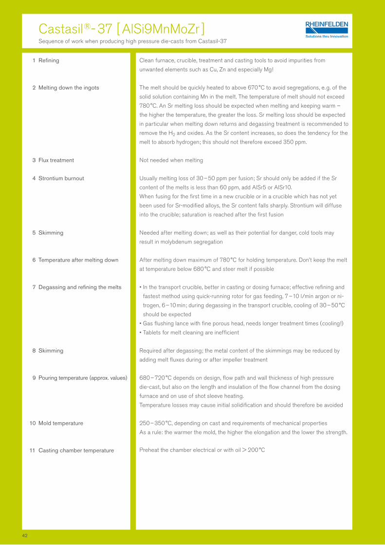
1 Refining
2 Melting down the ingots
3 Flux treatment
4 Strontium burnout
5 Skimming
6 Temperature after melting down
7 Degassing and refining the melts
8 Skimming
9 Pouring temperature ( approx. values )
10 Mold temperature
11 Casting chamber temperature
Castasil ®- 37 [ AlSi9MnMoZr ]Sequence of work when producing high pressure die-casts from Castasil-37
Clean furnace, crucible, treatment and casting tools to avoid impurities from
unwanted elements such as Cu, Zn and especially Mg !
The melt should be quickly heated to above 670 °C to avoid segregations, e. g. of the
solid solution containing Mn in the melt. The temperature of melt should not exceed
780 °C. An Sr melting loss should be expected when melting and keeping warm –
the higher the temperature, the greater the loss. Sr melting loss should be expected
in particular when melting down returns and degassing treatment is recommended to
remove the H2 and oxides. As the Sr content increases, so does the tendency for the
melt to absorb hydrogen; this should not therefore exceed 350 ppm.
Not needed when melting
Usually melting loss of 30 – 50 ppm per fusion; Sr should only be added if the Sr
content of the melts is less than 60 ppm, add AlSr5 or AlSr10.
When fusing for the first time in a new crucible or in a crucible which has not yet
been used for Sr-modified alloys, the Sr content falls sharply. Strontium will diffuse
into the crucible; saturation is reached after the first fusion
Needed after melting down; as well as their potential for danger, cold tools may
result in molybdenum segregation
After melting down maximum of 780 °C for holding temperature. Don’t keep the melt
at temperature below 680 °C and steer melt if possible
• In the transport crucible, better in casting or dosing furnace; effective refining and
fastest method using quick-running rotor for gas feeding, 7 – 10 l/min argon or ni-
trogen, 6 – 10 min; during degassing in the transport crucible, cooling of 30 – 50 °C
should be expected
• Gas flushing lance with fine porous head, needs longer treatment times ( cooling ! )
• Tablets for melt cleaning are inefficient
Required after degassing; the metal content of the skimmings may be reduced by
adding melt fluxes during or after impeller treatment
680 – 720 °C depends on design, flow path and wall thickness of high pressure
die-cast, but also on the length and insulation of the flow channel from the dosing
furnace and on use of shot sleeve heating.
Temperature losses may cause initial solidification and should therefore be avoided
250 – 350 °C, depending on cast and requirements of mechanical properties
As a rule: the warmer the mold, the higher the elongation and the lower the strength.
Preheat the chamber electrical or with oil > 200 °C
42
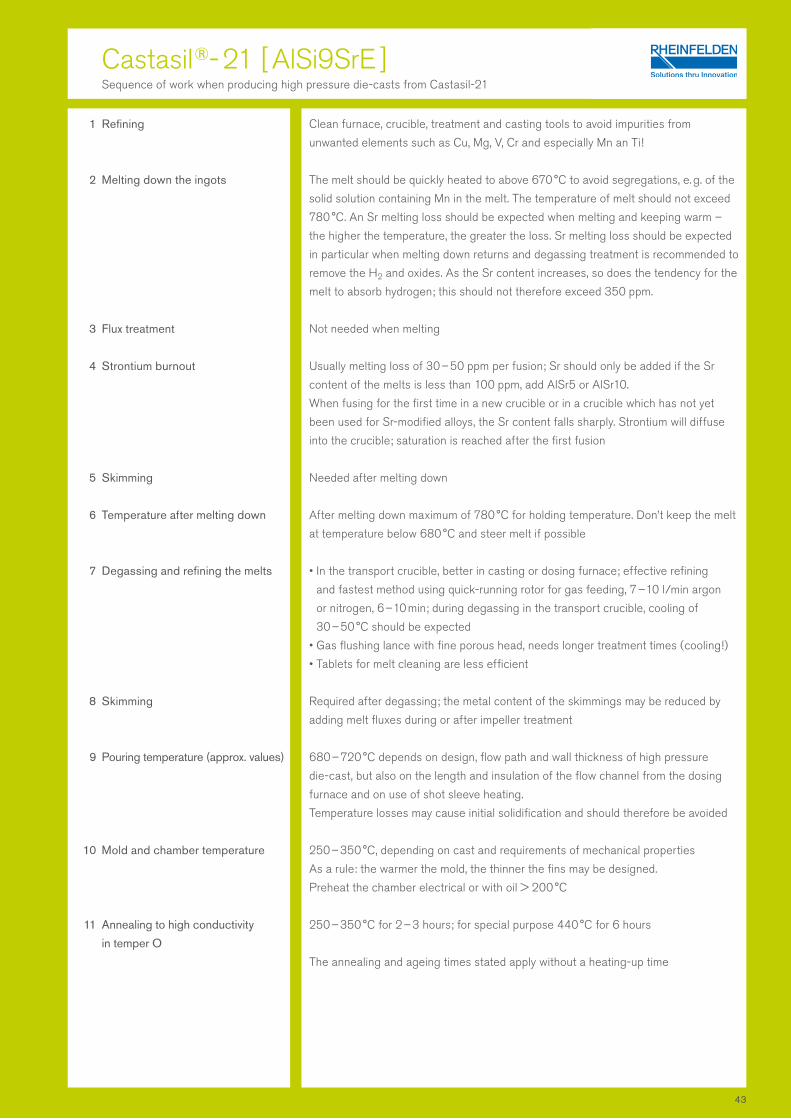
Castasil ®- 21 [ AlSi9SrE ]Sequence of work when producing high pressure die-casts from Castasil-21
1 Refining
2 Melting down the ingots
3 Flux treatment
4 Strontium burnout
5 Skimming
6 Temperature after melting down
7 Degassing and refining the melts
8 Skimming
9 Pouring temperature ( approx. values )
10 Mold and chamber temperature
11 Annealing to high conductivity
in temper O
Clean furnace, crucible, treatment and casting tools to avoid impurities from
unwanted elements such as Cu, Mg, V, Cr and especially Mn an Ti!
The melt should be quickly heated to above 670 °C to avoid segregations, e. g. of the
solid solution containing Mn in the melt. The temperature of melt should not exceed
780 °C. An Sr melting loss should be expected when melting and keeping warm –
the higher the temperature, the greater the loss. Sr melting loss should be expected
in particular when melting down returns and degassing treatment is recommended to
remove the H2 and oxides. As the Sr content increases, so does the tendency for the
melt to absorb hydrogen; this should not therefore exceed 350 ppm.
Not needed when melting
Usually melting loss of 30 – 50 ppm per fusion; Sr should only be added if the Sr
content of the melts is less than 100 ppm, add AlSr5 or AlSr10.
When fusing for the first time in a new crucible or in a crucible which has not yet
been used for Sr-modified alloys, the Sr content falls sharply. Strontium will diffuse
into the crucible; saturation is reached after the first fusion
Needed after melting down
After melting down maximum of 780 °C for holding temperature. Don’t keep the melt
at temperature below 680 °C and steer melt if possible
• In the transport crucible, better in casting or dosing furnace; effective refining
and fastest method using quick-running rotor for gas feeding, 7 – 10 l/min argon
or nitrogen, 6 – 10 min; during degassing in the transport crucible, cooling of
30 – 50 °C should be expected
• Gas flushing lance with fine porous head, needs longer treatment times ( cooling ! )
• Tablets for melt cleaning are less efficient
Required after degassing; the metal content of the skimmings may be reduced by
adding melt fluxes during or after impeller treatment
680 – 720 °C depends on design, flow path and wall thickness of high pressure
die-cast, but also on the length and insulation of the flow channel from the dosing
furnace and on use of shot sleeve heating.
Temperature losses may cause initial solidification and should therefore be avoided
250 – 350 °C, depending on cast and requirements of mechanical properties
As a rule: the warmer the mold, the thinner the fins may be designed.
Preheat the chamber electrical or with oil > 200 °C
250 – 350 °C for 2 – 3 hours; for special purpose 440 °C for 6 hours
The annealing and ageing times stated apply without a heating-up time
43

1 Melting down the ingots
2 Flux treatment
3 Magnesium burnout
4 Skimming
5 Temperature after melting down
6 Temperature in holding furnace
7 Degassing and refining the melts
8 Skimming
9 Grain refining
10 Modification
11 Pouring temperature ( approx. values )
12 Mold temperature and
casting chamber temperature
13 Quenching casts after removal
from mold
14 Heat treatment
15 stress-relief annealing
Magsimal ®- 59 [ AlMg5Si2Mn ]Sequence of work when producing high pressure die-casts from Magsimal-59
As quickly as possible in efficient furnaces to keep Mg melting loss, gas absorption
and oxidation of melts low; replenish preheated ingots and returns in small volumes to
avoid segregation; use refractory materials with a high clay content; avoid phospho-
rous and sodium absorption
Prohibited to use usual flux ! There is a risk of sodium (Na) pick up
Normally melting loss of 0.1 % per fusion, correction not normally needed; if the Mg
content is significantly below 5.0 %, add pure magnesium of maximum 0.5 %
Needed after melting down
Maximum of 780 °C ( check temperature ! )
Holding furnance temerature: 700 – 720 °C
Do not allow to fall below 650 °C and keep melt moving by means of:
• convection
• rotor ( impeller )
• use bottom injection of N2
• melt pouring
Do not use deep furnace with cover heating if melt is calm !
• Effective refining and fastest method using quick-running rotor for gas feeding,
7 – 10 l/min argon or nitrogen, 6 – 10 min
• Gas flushing lance with fine porous head, needs longer treatment times ( cooling ! )
• Gas flushing tablets do not achieve the necessary effect !
Careful skimming needed!
Only totally Na-free fluxes may be used to reduce the metal content of skimmings!
Prohibited !
Prohibited ! The elongation achievable would be reduced considerably
690 – 730 °C, varies depending on design, size and wall thickness of high pressure
die-casts
Mold surface temperature 250 °C to 350 °C, depending on cast and requirements of
mechanical properties
As a rule: the warmer the mold, the higher the elongation and the lower the strength.
Preheat the chamber electrical or with oil > 200 °C
Immediate quenching in water reduces the yield tensile strength and
increases elongation
Normally none
Only in special cases for T5 and O; if necessary, age T5 at up to 250 °C and
for up to 90 min, the yield tensile strength will increase and elongation decrease;
if necessary, age O at between 320 °C and 380 °C and for up to 90 min,
the yield tensile strength will decrease and elongation increase
44
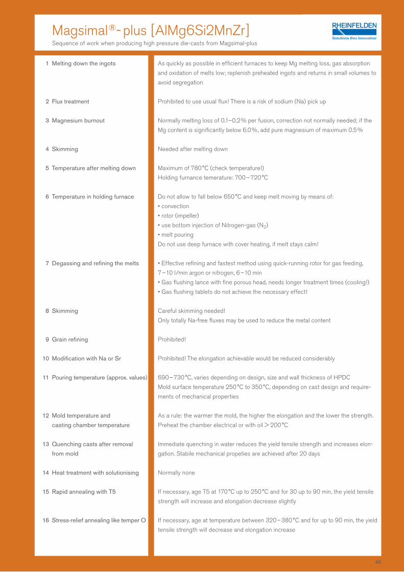
1 Melting down the ingots
2 Flux treatment
3 Magnesium burnout
4 Skimming
5 Temperature after melting down
6 Temperature in holding furnace
7 Degassing and refining the melts
8 Skimming
9 Grain refining
10 Modification with Na or Sr
11 Pouring temperature (approx. values)
12 Mold temperature and
casting chamber temperature
13 Quenching casts after removal
from mold
14 Heat treatment with solutionising
15 Rapid annealing with T5
16 Stress-relief annealing like temper O
As quickly as possible in efficient furnaces to keep Mg melting loss, gas absorption
and oxidation of melts low; replenish preheated ingots and returns in small volumes to
avoid segregation
Prohibited to use usual flux! There is a risk of sodium (Na) pick up
Normally melting loss of 0.1–0.2 % per fusion, correction not normally needed; if the
Mg content is significantly below 6.0 %, add pure magnesium of maximum 0.5 %
Needed after melting down
Maximum of 780 °C (check temperature!)
Holding furnance temerature: 700 – 720 °C
Do not allow to fall below 650 °C and keep melt moving by means of:
• convection
• rotor (impeller)
• use bottom injection of Nitrogen-gas (N2)
• melt pouring
Do not use deep furnace with cover heating, if melt stays calm!
• Effective refining and fastest method using quick-running rotor for gas feeding,
7 – 10 l/min argon or nitrogen, 6 – 10 min
• Gas flushing lance with fine porous head, needs longer treatment times (cooling!)
• Gas flushing tablets do not achieve the necessary effect!
Careful skimming needed!
Only totally Na-free fluxes may be used to reduce the metal content
Prohibited!
Prohibited! The elongation achievable would be reduced considerably
690 – 730 °C, varies depending on design, size and wall thickness of HPDC
Mold surface temperature 250 °C to 350 °C, depending on cast design and require-
ments of mechanical properties
As a rule: the warmer the mold, the higher the elongation and the lower the strength.
Preheat the chamber electrical or with oil > 200 °C
Immediate quenching in water reduces the yield tensile strength and increases elon-
gation. Stabile mechanical propeties are achieved after 20 days
Normally none
If necessary, age T5 at 170 °C up to 250 °C and for 30 up to 90 min, the yield tensile
strength will increase and elongation decrease slightly
If necessary, age at temperature between 320 – 380 °C and for up to 90 min, the yield
tensile strength will decrease and elongation increase
Magsimal ®- plus [ AlMg6Si2MnZr ]Sequence of work when producing high pressure die-casts from Magsimal-plus
45
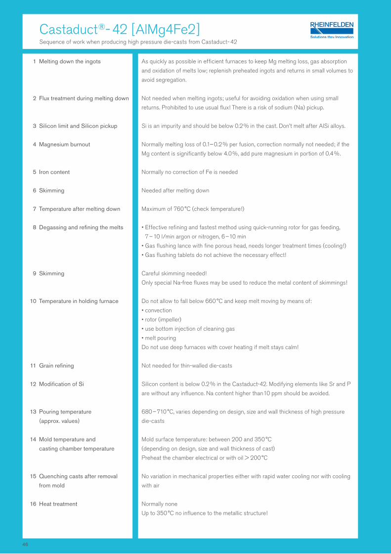
1 Melting down the ingots
2 Flux treatment during melting down
3 Silicon limit and Silicon pickup
4 Magnesium burnout
5 Iron content
6 Skimming
7 Temperature after melting down
8 Degassing and refining the melts
9 Skimming
10 Temperature in holding furnace
11 Grain refining
12 Modification of Si
13 Pouring temperature
(approx. values)
14 Mold temperature and
casting chamber temperature
15 Quenching casts after removal
from mold
16 Heat treatment
As quickly as possible in efficient furnaces to keep Mg melting loss, gas absorption
and oxidation of melts low; replenish preheated ingots and returns in small volumes to
avoid segregation.
Not needed when melting ingots; useful for avoiding oxidation when using small
returns. Prohibited to use usual flux! There is a risk of sodium (Na) pickup.
Si is an impurity and should be below 0.2 % in the cast. Don’t melt after AlSi alloys.
Normally melting loss of 0.1– 0.2 % per fusion, correction normally not needed; if the
Mg content is significantly below 4.0 %, add pure magnesium in portion of 0.4 %.
Normally no correction of Fe is needed
Needed after melting down
Maximum of 760 °C (check temperature!)
• Effective refining and fastest method using quick-running rotor for gas feeding,
7 – 10 l/min argon or nitrogen, 6 – 10 min
• Gas flushing lance with fine porous head, needs longer treatment times (cooling!)
• Gas flushing tablets do not achieve the necessary effect!
Careful skimming needed!
Only special Na-free fluxes may be used to reduce the metal content of skimmings!
Do not allow to fall below 660 °C and keep melt moving by means of:
• convection
• rotor (impeller)
• use bottom injection of cleaning gas
• melt pouring
Do not use deep furnaces with cover heating if melt stays calm!
Not needed for thin-walled die-casts
Silicon content is below 0.2 % in the Castaduct-42. Modifying elements like Sr and P
are without any influence. Na content higher than 10 ppm should be avoided.
680 – 710 °C, varies depending on design, size and wall thickness of high pressure
die-casts
Mold surface temperature: between 200 and 350 °C
(depending on design, size and wall thickness of cast)
Preheat the chamber electrical or with oil > 200 °C
No variation in mechanical properties either with rapid water cooling nor with cooling
with air
Normally none
Up to 350 °C no influence to the metallic structure!
Castaduct ®- 42 [ AlMg4Fe2 ]Sequence of work when producing high pressure die-casts from Castaduct - 42
46
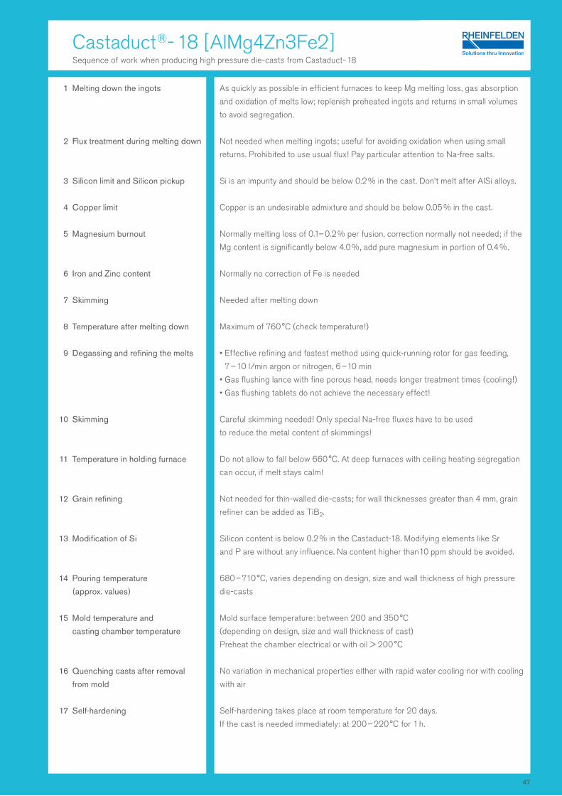
Castaduct ®- 18 [ AlMg4Zn3Fe2 ]Sequence of work when producing high pressure die-casts from Castaduct - 18
1 Melting down the ingots
2 Flux treatment during melting down
3 Silicon limit and Silicon pickup
4 Copper limit
5 Magnesium burnout
6 Iron and Zinc content
7 Skimming
8 Temperature after melting down
9 Degassing and refining the melts
10 Skimming
11 Temperature in holding furnace
12 Grain refining
13 Modification of Si
14 Pouring temperature
(approx. values)
15 Mold temperature and
casting chamber temperature
16 Quenching casts after removal
from mold
17 Self-hardening
As quickly as possible in efficient furnaces to keep Mg melting loss, gas absorption
and oxidation of melts low; replenish preheated ingots and returns in small volumes
to avoid segregation.
Not needed when melting ingots; useful for avoiding oxidation when using small
returns. Prohibited to use usual flux! Pay particular attention to Na-free salts.
Si is an impurity and should be below 0.2 % in the cast. Don’t melt after AlSi alloys.
Copper is an undesirable admixture and should be below 0.05 % in the cast.
Normally melting loss of 0.1– 0.2 % per fusion, correction normally not needed; if the
Mg content is significantly below 4.0 %, add pure magnesium in portion of 0.4 %.
Normally no correction of Fe is needed
Needed after melting down
Maximum of 760 °C (check temperature!)
• Effective refining and fastest method using quick-running rotor for gas feeding,
7 – 10 l/min argon or nitrogen, 6 – 10 min
• Gas flushing lance with fine porous head, needs longer treatment times (cooling!)
• Gas flushing tablets do not achieve the necessary effect!
Careful skimming needed! Only special Na-free fluxes have to be used
to reduce the metal content of skimmings!
Do not allow to fall below 660 °C. At deep furnaces with ceiling heating segregation
can occur, if melt stays calm!
Not needed for thin-walled die-casts; for wall thicknesses greater than 4 mm, grain
refiner can be added as TiB2.
Silicon content is below 0.2 % in the Castaduct-18. Modifying elements like Sr
and P are without any influence. Na content higher than 10 ppm should be avoided.
680 – 710 °C, varies depending on design, size and wall thickness of high pressure
die-casts
Mold surface temperature: between 200 and 350 °C
(depending on design, size and wall thickness of cast)
Preheat the chamber electrical or with oil > 200 °C
No variation in mechanical properties either with rapid water cooling nor with cooling
with air
Self-hardening takes place at room temperature for 20 days.
If the cast is needed immediately: at 200 – 220 °C for 1 h.
47
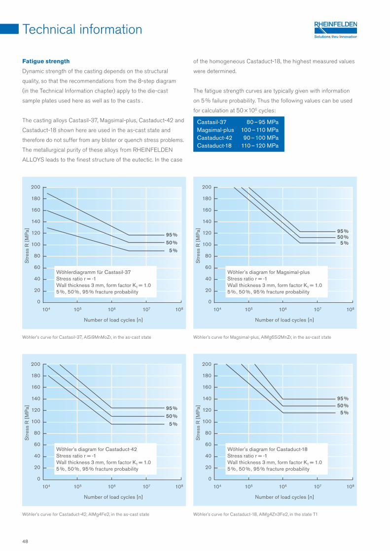
104 105 106 107 108
200
180
160
140
120
100
80
60
40
20
0
95 %50 %
5 %
104 105 106 107 108
200
180
160
140
120
100
80
60
40
20
0
95 %50 %
5 %
104 105 106 107 108104 105 106 107 108
200
180
160
140
120
100
80
60
40
20
0
200
180
160
140
120
100
80
60
40
20
0
95 %50 %
5 %95 %50 %
5 %
Fatigue strength
Dynamic strength of the casting depends on the structural
quality, so that the recommendations from the 8-step diagram
(in the Technical Information chapter) apply to the die-cast
sample plates used here as well as to the casts .
The casting alloys Castasil-37, Magsimal-plus, Castaduct-42 and
Castaduct -18 shown here are used in the as-cast state and
therefore do not suffer from any blister or quench stress problems.
The metallurgical purity of these alloys from RHEINFELDEN
ALLOYS leads to the finest structure of the eutectic. In the case
of the homogeneous Castaduct-18, the highest measured values
were determined.
The fatigue strength curves are typically given with information
on 5 % failure probability. Thus the following values can be used
for calculation at 50 × 106 cycles:
Castasil-37 80 – 95 MPaMagsimal-plus 100 – 110 MPaCastaduct-42 90 – 100 MPaCastaduct-18 110 – 120 MPa
Technical information
Wöhler’s curve for Magsimal-plus, AlMg6Si2MnZr, in the as-cast state
Wöhler’s curve for Castaduct-18, AlMg4Zn3Fe2, in the state T1
Wöhler’s curve for Castasil-37, AlSi9MnMoZr, in the as-cast state
Wöhler’s curve for Castaduct-42, AlMg4Fe2, in the as-cast state
Number of load cycles [n]
Number of load cycles [n]
Number of load cycles [n]
Number of load cycles [n]
Str
ess
R [
MP
a]S
tres
s R
[M
Pa]
Str
ess
R [
MP
a]S
tres
s R
[M
Pa]
Wöhlerdiagramm für Castasil-37 Stress ratio r = -1Wall thickness 3 mm, form factor K t = 1.05 %, 50 %, 95 % fracture probability
Wöhler’s diagram for Magsimal-plus Stress ratio r = -1Wall thickness 3 mm, form factor K t = 1.05 %, 50 %, 95 % fracture probability
Wöhler’s diagram for Castaduct-18Stress ratio r = -1Wall thickness 3 mm, form factor K t = 1.05 %, 50 %, 95 % fracture probability
Wöhler’s diagram for Castaduct-42Stress ratio r = -1Wall thickness 3 mm, form factor K t = 1.05 %, 50 %, 95 % fracture probability
48

C
D D
A
B
C
A
B
B
B
C
Technical information
Design of structural die-casts
Die-casted structural components are typically large stability-
giving components, in which high component reliability is required
and which should withstand high deformations in the event of
crash of vehicles. This structural casts has to meet demands for
high strength and elongation with fewest errors as possible in the
cast structure. A structural cast is connected in individual areas
with other components by welding, gluing, riveting or crimping.
The material-side fulfillment of high strength requirements, as
possible without heat treatment to be applied, improves the
dimensional accuracy of structural casts. The additional demand
for lightweight construction is also met by thin-walled design and
high functional integration.
Important for the production of structural casts is a castable
component design with reliable processing technology of the
HPDC alloys presented in this manual. Some hints for the design
of the casts as well as the die-casting molds are given here. We
recommend that you follow these design suggestions, especially
when using our Magsimal-59 / -plus and Castaduct-42 alloys.
On the machine side, thin-walled structural casts with wall thick-
nesses of around 2.0 mm can be realized with flow path length
of approximately 1.0 m. However, it is important to ensure that
the wall thickness from casting ingate section to the end of mold
filling is performed from thick to thin, so for example from 3.5 mm
to 2.0 mm.
In the case of the more strong shrinking AlMg casting alloys, the
draft angles should be performed on contours and cores prefer-
ably minimum 1.5 °. Cast contours that tend to shrink more strong,
as well as deep, slender fin contours must be supported with
sufficient amount of ejectors for demolding from the die-casting
mold. Examples are expressed in Fig. 1.
The diameter of the ejector pins should not be less than 6.0 mm,
since AlMg casting alloys are expected to have significantly high-
er demolding forces compared to AlSi casting alloys. Also, the
risk of buckling of the ejector pins can be avoided in a practicable
way. In practice, the demolding forces are about one-third higher
and may be even higher depending on the cast design. Additional
ejector pins also significantly reduce the surface pressure on the
hot cast and with this the possible distortion of the cast.
Fig. 2: An example of good fin design
A: Fin node reducing massive concentration
B: High incoming forces are spreaded by several fins
C: Thicker diameter of ejector pins to reduce pressure force
Fig. 1: An example of good fin design
A: Thin fin with lowered height in the middle of the length, also to reduce thickness at the fin ground
B: Adjusted core depth in small core areas
C: Ejector pin location in a tilted wall
D: Additional core pins in the area of narrow high fins
Technical information
49
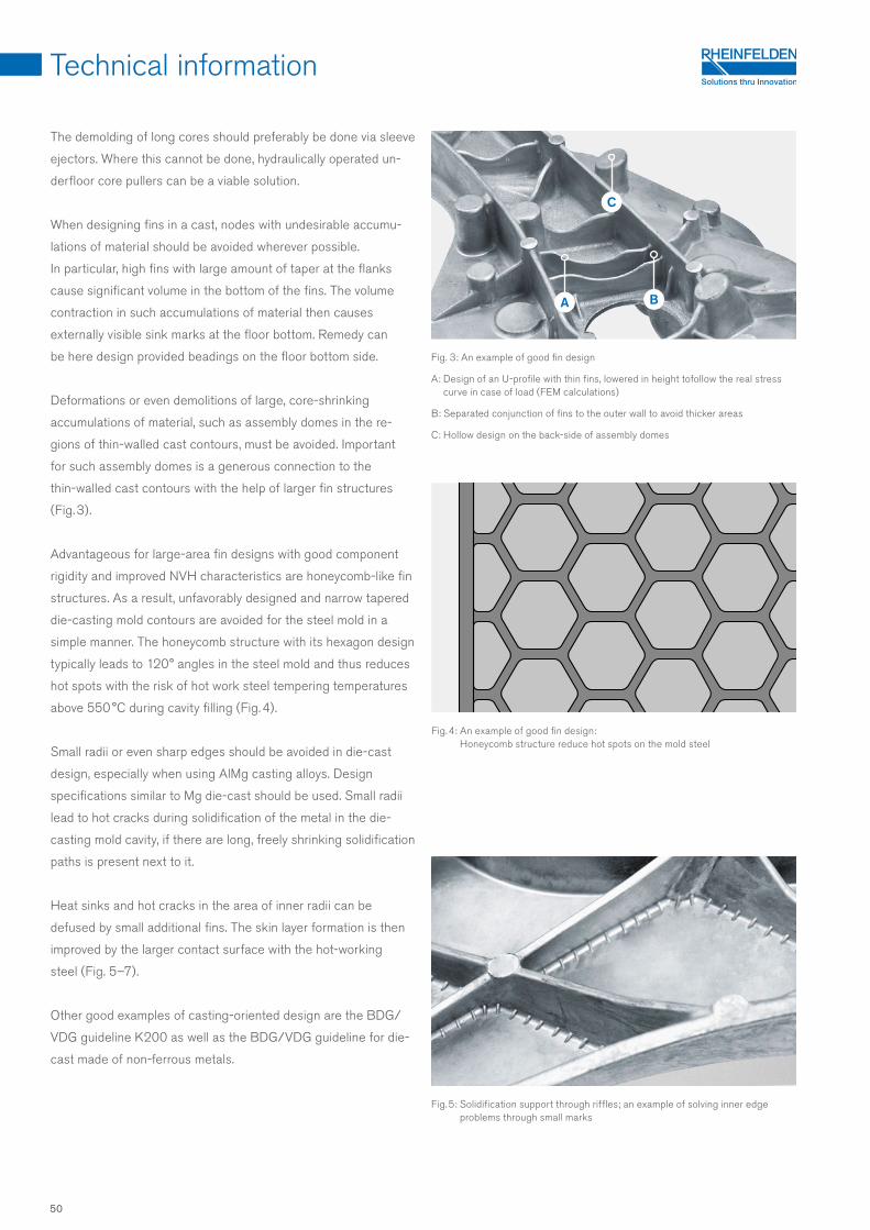
C
A B
The demolding of long cores should preferably be done via sleeve
ejectors. Where this cannot be done, hydraulically operated un-
derfloor core pullers can be a viable solution.
When designing fins in a cast, nodes with undesirable accumu-
lations of material should be avoided wherever possible.
In particular, high fins with large amount of taper at the flanks
cause significant volume in the bottom of the fins. The volume
contraction in such accumulations of material then causes
externally visible sink marks at the floor bottom. Remedy can
be here design provided beadings on the floor bottom side.
Deformations or even demolitions of large, core-shrinking
accumulations of material, such as assembly domes in the re-
gions of thin-walled cast contours, must be avoided. Important
for such assembly domes is a generous connection to the
thin-walled cast contours with the help of larger fin structures
(Fig. 3).
Advantageous for large-area fin designs with good component
rigidity and improved NVH characteristics are honeycomb-like fin
structures. As a result, unfavorably designed and narrow tapered
die-casting mold contours are avoided for the steel mold in a
simple manner. The honeycomb structure with its hexagon design
typically leads to 120 ° angles in the steel mold and thus reduces
hot spots with the risk of hot work steel tempering temperatures
above 550 °C during cavity filling (Fig. 4).
Small radii or even sharp edges should be avoided in die-cast
design, especially when using AlMg casting alloys. Design
specifications similar to Mg die-cast should be used. Small radii
lead to hot cracks during solidification of the metal in the die-
casting mold cavity, if there are long, freely shrinking solidification
paths is present next to it.
Heat sinks and hot cracks in the area of inner radii can be
defused by small additional fins. The skin layer formation is then
improved by the larger contact surface with the hot-working
steel (Fig. 5–7).
Other good examples of casting-oriented design are the BDG/
VDG guideline K200 as well as the BDG/VDG guideline for die-
cast made of non-ferrous metals.
Fig. 5: Solidification support through riffles; an example of solving inner edge problems through small marks
Fig. 3: An example of good fin design
A: Design of an U-profile with thin fins, lowered in height tofollow the real stress curve in case of load (FEM calculations)
B: Separated conjunction of fins to the outer wall to avoid thicker areas
C: Hollow design on the back-side of assembly domes
Fig. 4: An example of good fin design: Honeycomb structure reduce hot spots on the mold steel
Technical information
50

C
A
B
C
A
B
Technical information
Design of the die-casting mold
For the production of large and thin-walled structural die-casts,
not only the casting alloy used, but also the die-casting mold
itself has to be designed to reproduce long flow paths.
Ideal for thin-walled die-casts with Castaduct-42, Magsimal-59
or Magsimal-plus is the close-to-contour design of the cool-
ing and tempering inside the mold inserts. For the die-casting
process, a temperature control of the mold inserts to over 200 °C
is recommended.
An adjustment of the thermal balance of the die-casting mold by
spraying the die-casting mold contour with the help of water
in combination with release agents should be avoided as far
as possible. This is because stress cracks on the steel occur
early when the temperature difference is particularly high.
It is recommended to carry out the release agent application
using a minimum-quantity spraying process. In this case, water,
powder or oil-based release agents can be used. Modern
simulation programs are of great help in the design of the
thermal balance of a die-casting mold.
An intensive cooling of the mold inserts in the area of the cast
runner allows rapid removal of the cast from the die-casting
mold. Although a flat and wide developed cast runner increases
the pressure surface within the die-casting mold and thus the
necessary locking force, but it leads to significantly reduced so-
lidification times. Thus, the casts can be demold in a faster way.
Furthermore, large, flat cast runners can be divided more easily
with less effort during the deburring cut. An advantage when
it comes to the handling of return scraps.
The runner as well as the ingate section has to be designed for
low turbulence and fluid flow favorable run, so without small radii
and without sharp-edged transitions. Because these increase
the flow resistance significantly and it is a greater casting force
needed for the cavity filling. Cavitation effects lead to local
vacuum zones with cross-sectional constrictions in flow-cross
sections and can suck in air via the die-casting mold parting lines
and with this into the melt.
The runner ingate section has to be placed into areas of the cast,
where the incoming melt do not immediately encounters a trans-
verse and rise barrier inside of the cavity within the flow direction.
This leads, regardless of the casting alloy used, to very strong
friction of the melt on the die-casting mold contour, so very
quickly to local heat up, and as a result, to sticking and strong
erosion. Even a significant loss of flow energy is expected.
Fig. 6: HPDC design to ensure forced solidification in the cast
A: Thinnered wall with small waffle pattern design to enlarge contact area
B: Separated fin connections
C: Outer contour casted with core to cast a wall with uniform thickness
Fig. 7: Good HPDC design to ensure forced solidification in the cast
A: Thin wall with narrow small waffle pattern design to enlarge intensively the contact surface
B: Assembly domes with hollow casted center
C: Solving inner edge problems through small marks
Technical information
51
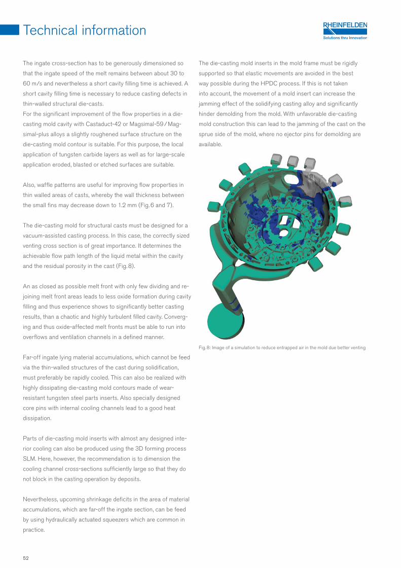
The ingate cross-section has to be generously dimensioned so
that the ingate speed of the melt remains between about 30 to
60 m/s and nevertheless a short cavity filling time is achieved. A
short cavity filling time is necessary to reduce casting defects in
thin-walled structural die-casts.
For the significant improvement of the flow properties in a die-
casting mold cavity with Castaduct-42 or Magsimal-59 / Mag-
simal-plus alloys a slightly roughened surface structure on the
die-casting mold contour is suitable. For this purpose, the local
application of tungsten carbide layers as well as for large-scale
application eroded, blasted or etched surfaces are suitable.
Also, waffle patterns are useful for improving flow properties in
thin walled areas of casts, whereby the wall thickness between
the small fins may decrease down to 1.2 mm (Fig. 6 and 7).
The die-casting mold for structural casts must be designed for a
vacuum-assisted casting process. In this case, the correctly sized
venting cross section is of great importance. It determines the
achievable flow path length of the liquid metal within the cavity
and the residual porosity in the cast (Fig. 8).
An as closed as possible melt front with only few dividing and re-
joining melt front areas leads to less oxide formation during cavity
filling and thus experience shows to significantly better casting
results, than a chaotic and highly turbulent filled cavity. Converg-
ing and thus oxide-affected melt fronts must be able to run into
overflows and ventilation channels in a defined manner.
Far-off ingate lying material accumulations, which cannot be feed
via the thin-walled structures of the cast during solidification,
must preferably be rapidly cooled. This can also be realized with
highly dissipating die-casting mold contours made of wear-
resistant tungsten steel parts inserts. Also specially designed
core pins with internal cooling channels lead to a good heat
dissipation.
Parts of die-casting mold inserts with almost any designed inte-
rior cooling can also be produced using the 3D forming process
SLM. Here, however, the recommendation is to dimension the
cooling channel cross-sections sufficiently large so that they do
not block in the casting operation by deposits.
Nevertheless, upcoming shrinkage deficits in the area of material
accumulations, which are far-off the ingate section, can be feed
by using hydraulically actuated squeezers which are common in
practice.
The die-casting mold inserts in the mold frame must be rigidly
supported so that elastic movements are avoided in the best
way possible during the HPDC process. If this is not taken
into account, the movement of a mold insert can increase the
jamming effect of the solidifying casting alloy and significantly
hinder demolding from the mold. With unfavorable die-casting
mold construction this can lead to the jamming of the cast on the
sprue side of the mold, where no ejector pins for demolding are
available.
Technical information
Fig. 8: Image of a simulation to reduce entrapped air in the mold due better venting
52
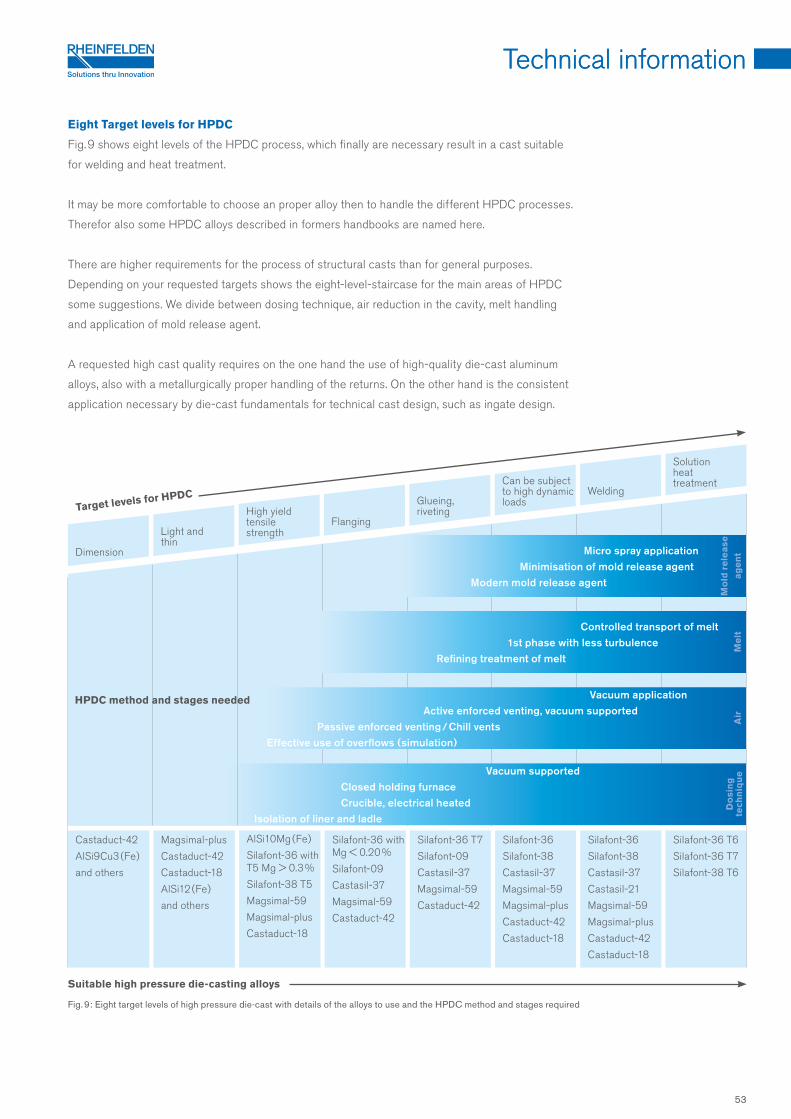
Technical information
Eight Target levels for HPDC
Fig. 9 shows eight levels of the HPDC process, which finally are necessary result in a cast suitable
for welding and heat treatment.
It may be more comfortable to choose an proper alloy then to handle the different HPDC processes.
Therefor also some HPDC alloys described in formers handbooks are named here.
There are higher requirements for the process of structural casts than for general purposes.
Depending on your requested targets shows the eight-level-staircase for the main areas of HPDC
some suggestions. We divide between dosing technique, air reduction in the cavity, melt handling
and application of mold release agent.
A requested high cast quality requires on the one hand the use of high-quality die-cast aluminum
alloys, also with a metallurgically proper handling of the returns. On the other hand is the consistent
application necessary by die-cast fundamentals for technical cast design, such as ingate design.
Suitable high pressure die-casting alloys
Fig. 9: Eight target levels of high pressure die-cast with details of the alloys to use and the HPDC method and stages required
AlSi10Mg ( Fe )
Silafont-36 with T5 Mg > 0.3 %
Silafont-38 T5
Magsimal-59
Magsimal-plus
Castaduct-18
Dimension
Light and thin
High yield tensile strength
Flanging
Glueing, riveting
Can be subject to high dynamic loads
Welding
Castaduct-42
AlSi9Cu3 ( Fe )
and others
Magsimal-plus
Castaduct-42
Castaduct-18
AlSi12 ( Fe )
and others
Silafont-36 with Mg < 0.20 %
Silafont-09
Castasil-37
Magsimal-59
Castaduct-42
Silafont-36 T7
Silafont-09
Castasil-37
Magsimal-59
Castaduct-42
Silafont-36
Silafont-38
Castasil-37
Magsimal-59
Magsimal-plus
Castaduct-42
Castaduct-18
Silafont-36
Silafont-38
Castasil-37
Castasil-21
Magsimal-59
Magsimal-plus
Castaduct-42
Castaduct-18
Silafont-36 T6
Silafont-36 T7
Silafont-38 T6
Micro spray application Minimisation of mold release agent Modern mold release agent
Mo
ld r
ele
ase
a
ge
nt
Target levels for HPDC
Controlled transport of melt 1st phase with less turbulence Refining treatment of melt
Me
ltA
ir
Vacuum supported Closed holding furnace Crucible, electrical heated Isolation of liner and ladle
Do
sin
gte
chn
iqu
e
HPDC method and stages needed Vacuum application Active enforced venting, vacuum supported Passive enforced venting / Chill vents Effective use of overflows (simulation)
Solution heat treatment
Technical information
Fatigue strength 48
Design of structural die-casts 49
Design of the die-casting mold 51
Eight Target levels for HPDC
53
53
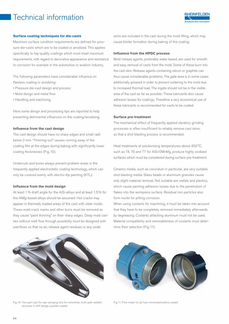
Surface coating techniques for die-casts
Maximum surface condition requirements are defined for pres-
sure die-casts which are to be coated or anodized. This applies
specifically to top-quality coatings which must meet maximum
requirements, with regard to decorative appearance and resistance
to corrosion for example in the automotive or aviation industry.
The following parameters have considerable influence on
flawless coating or anodizing:
• Pressure die-cast design and process
• Mold design and metal flow
• Handling and machining
Here some design and processing tips are reported to help
preventing detrimental influences on the coating/anodizing.
Influence from the cast design
The cast design should have no sharp edges and small radii
below 2 mm. “Thinning-out” causes running away of the
coating film at the edges during baking with significantly lower
coating thicknesses (Fig. 10).
Undercuts and bores always present problem areas in the
frequently applied electrostatic coating technology, which can
only be covered evenly with electro-dip painting (KTL).
Influence from the mold design
At least 1 % draft angle for the AlSi-alloys and at least 1.5 % for
the AlMg-based alloys should be assumed. Hot cracks may
appear in thermally loaded areas of the cast with older molds.
These mold crack marks and other burrs must be removed as
they cause “paint thinning” on their sharp edges. Deep mold cavi-
ties without melt flow through possibility must be designed with
overflows so that no air, release agent residues or any oxide
skins are included in the cast during the mold filling, which may
cause blister formation during baking of the coating.
Influence from the HPDC process
Mold release agents, preferably water based, are used for smooth
and easy removal of casts from the mold. Some of these burn into
the cast skin. Release agents containing silicon or graphite can
thus cause considerable problems. The gate area is in some cases
additionally greased in order to prevent soldering to the mold due
to increased thermal load. The ingate should not be in the visible
area of the cast as far as possible. These lubricants also cause
adhesion losses for coatings. Therefore a very economical use of
these lubricants is recommended for casts to be coated.
Surface pre-treatment
The mechanical effect of frequently applied vibratory grinding
processes is often insufficient to reliably remove cast skins,
so that a shot blasting process is recommended.
Heat treatments at solutionizing temperatures above 450 °C,
such as T4, T6 and T7 for AlSi10MnMg, produce highly oxidized
surfaces which must be considered during surface pre-treatment.
Ceramic media, such as corundum in particular, are very suitable
shot blasting media. Glass beads or aluminum granules cause
only slight material removal. Not suitable are metals and plastics,
which cause painting adhesion losses due to the penetration of
flakes into the workpiece surface. Residual iron particles also
form nuclei for pitting corrosion.
When using coolants for machining, it must be taken into account
that they have to be completely removed immediately afterwards
by degreasing. Coolants attacking aluminum must not be used.
Material compatibility and removableness of coolants must deter-
mine their selection (Fig. 11).
Fig. 10: Two-part cast for rear swinging fork for motorbike; multi-path welded structure in stiff design; powder coated
Fig. 11: Flow meter for jet fuel; chromated before coated
Technical information
54
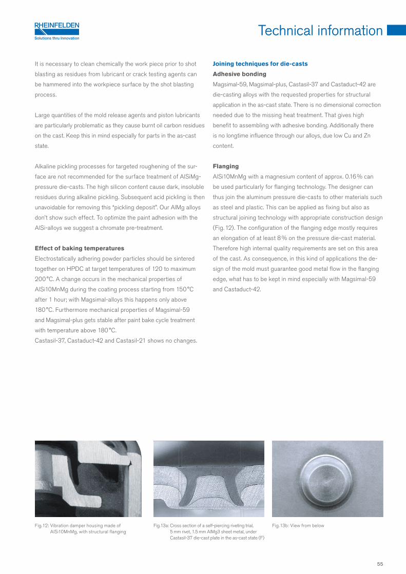
Technical information
It is necessary to clean chemically the work piece prior to shot
blasting as residues from lubricant or crack testing agents can
be hammered into the workpiece surface by the shot blasting
process.
Large quantities of the mold release agents and piston lubricants
are particularly problematic as they cause burnt oil carbon residues
on the cast. Keep this in mind especially for parts in the as-cast
state.
Alkaline pickling processes for targeted roughening of the sur-
face are not recommended for the surface treatment of AlSiMg-
pressure die-casts. The high silicon content cause dark, insoluble
residues during alkaline pickling. Subsequent acid pickling is then
unavoidable for removing this “pickling deposit”. Our AlMg alloys
don’t show such effect. To optimize the paint adhesion with the
AlSi-alloys we suggest a chromate pre-treatment.
Effect of baking temperatures
Electrostatically adhering powder particles should be sintered
together on HPDC at target temperatures of 120 to maximum
200 °C. A change occurs in the mechanical properties of
AlSi10MnMg during the coating process starting from 150 °C
after 1 hour; with Magsimal-alloys this happens only above
180 °C. Furthermore mechanical properties of Magsimal-59
and Magsimal-plus gets stable after paint bake cycle treatment
with temperature above 180 °C.
Castasil-37, Castaduct-42 and Castasil-21 shows no changes.
Joining techniques for die-casts
Adhesive bonding
Magsimal-59, Magsimal-plus, Castasil-37 and Castaduct-42 are
die-casting alloys with the requested properties for structural
application in the as-cast state. There is no dimensional correction
needed due to the missing heat treatment. That gives high
benefit to assembling with adhesive bonding. Additionally there
is no longtime influence through our alloys, due low Cu and Zn
content.
Flanging
AlSi10MnMg with a magnesium content of approx. 0.16 % can
be used particularly for flanging technology. The designer can
thus join the aluminum pressure die-casts to other materials such
as steel and plastic. This can be applied as fixing but also as
structural joining technology with appropriate construction design
(Fig. 12). The configuration of the flanging edge mostly requires
an elongation of at least 8 % on the pressure die-cast material.
Therefore high internal quality requirements are set on this area
of the cast. As consequence, in this kind of applications the de-
sign of the mold must guarantee good metal flow in the flanging
edge, what has to be kept in mind especially with Magsimal-59
and Castaduct-42.
Fig. 13a: Cross section of a self-piercing riveting trial, 5 mm rivet, 1.5 mm AlMg3 sheet metal, under Castasil-37 die-cast plate in the as-cast state (F)
Fig. 12: Vibration damper housing made of AlSi10MnMg, with structural flanging
Fig. 13b: View from below
Technical information
55
Patented by RHEINFELDEN ALLOYS are the alloys Silafont-38, Castasil-37 and Castasil-21, Magsimal-59 and Magsimal-plus as
well as Castaduct-42 and Castaduct-18.
We would like to thank all our business partners who have provided have provided casts or photographs for this publication.
Special thanks to AUDI AG for the ASF picture on the front side and RWP Simtec for a picture about casting simulation.
All the details in this publication have been checked and are provided to the best of our knowledge. But just like all technical
recommendations for applications, they are not binding, are not covered by our contractual obligations ( this also applies to copy-
rights of third parties ) and we do not assume liability for them. In particular they are not promises of characteristics and do
not exempt the user from checking the products we supply for suitability for their intended purpose. Reprints, translations and
copies, including extracts, require our express approval. New alloy developments made as technology progresses after printing
are included in later versions. Version 3 – 08/2018
High pressure die-casts made from Silafont-36, Silafont-38 and
Castasil-37 are particularly well suited to welding, with both MIG
and TIG standard methods. The S - AlSi5 or S - AlSi10 welding
addition material is preferred for welded designs with AlMgSi0.5
wrought alloys.
The AlMg-based alloys, like Magsimal-59, Magsimal-plus as well
as Castaduct-42 and Castaduct-18 have a higher shrinkage rate
and force than AlSi HPDC alloys. Mold release agents recently
developed for work with alloy family improve both the ease
of flow, i.e. ability to slide during ejection, and therefore the suit-
ability of the high pressure die-casts for welding.
Design welding with casts made from Magsimal-59 and Magsi-
mal-plus and Castaduct-42 are undertaken with the addition ma-
terial S - AlMg4.5Mn using the TIG method. Unlike the case with
elongation, the mechanical properties in the heat influence zone
are hardly affected. The use of S-AlSi5 in AlMg die-cast alloys
would result in a decrease in elongation, and also to cracking in
the weld.
All die-casting alloys are well suited for friction stir welding or
spot welding. Spot and laser beam welding processes must take
the special features of aluminum material into account.
Self-piercing riveting
Joints in which the cast is the lower layer in the riveting joint,
have particularly high requirements concerning the absence
of defects in the casting material. Figures 13a and 13b show the
result of a self-piercing riveting trial in our laboratory.
It should be noted that Castasil-37 can be self-piercing riveted
in the as-cast state also under these severe design conditions,
i.e. using a rivet mold with flat geometry. The Castasil-37 batch
used for this trial had a yield strenght of 114 MPa, an ultimate
tensile strength of 255 MPa and 14 % elongation. A further
improvement in deformability is achieved in temper O.
Ask for our experience in self-piercing riveting with our other
alloys for structural design demands.
Welding
All here mentioned HPDC alloys are suitable for friction stir
welding and other pressure welding methods.
The suitability of HPDC for fusion welding is highly dependent
on the processes. There is no tendency for hot tearing with these
die-cast alloys. Alloys, melting and die-casting methods which
ensure low gas absorption and oxide impurity during HPDC are
needed.
The designer may place weld seams in zones with less loading,
but preferable they should also be close to the ingate, due cast
quality generally is there higher.
Technical information
Wall thickness 4 mm
YTS[MPa]
UTS[MPa]
E[ %]
Ma-59 not welded 165 287 17
Ma-59 welded 148 246 6
56

GRU
PPE
DREI®
082
018
RHEINFELDEN ALLOYS GmbH & Co. KG A company of the ALUMINIUM RHEINFELDEN group Sales and Customer Support Friedrichstraße 80 D-79618 Rheinfelden
Tel. + 49 . 76 23 . 93-490 Fax + 49 . 76 23 . 93-546
alloys @ rheinfelden-alloys.eu www.rheinfelden-alloys.eu