prima spanaesthetic machine range service manualdiagramasde.com/diagramas/otros2/sp service...
TRANSCRIPT

Prima SP AnaestheticMachine RangeService Manual
Quality and Assurance in Anaesthesia

THE IMPORTANCE OF PATIENT MONITORING
WARNING
Anaesthetic systems have the capabilityto deliver mixtures of gases and vapoursto the patient which could cause injury ordeath unless controlled by a qualifiedanaesthetist.
There can be considerable variation inthe effect of anaesthetic drugs on indi-vidual patients so that the setting andobservation of control levels on theanaesthesia systems does not in itselfensure total patient safety.
Anaesthesia system monitors and patientmonitors are very desirable aids for theanaesthetist but are not true clinical moni-tors as the condition of the patient isalso dependent on his respiration and thefunctioning of his cardio-vascular system.
IT IS ESSENTIAL THAT THESE ELEMENTSARE MONITORED FREQUENTLY ANDREGULARLY AND THAT ANY OBSERVA-TIONS ARE GIVEN PRECEDENCE OVERMACHINE CONTROL PARAMETERS INJUDGING THE STATE OF A CLINICALPROCEDURE.

Servicing and Repairs
In order to ensure the full operational life ofthis anaesthetic machine, servicing by aPenlon-trained engineer should beundertaken periodically.
The machine must be serviced to theschedule detailed in section 8.Details of these operations are given in thisService Manual, available only for Penlontrained engineers.
For any enquiry regarding the servicing orrepair of this machine, contact the nearestaccredited Penlon agent:
or communicate directly with:
Technical Support DepartmentPenlon LimitedAbingdon Science Park, Barton LaneAbingdonOX14 3PHUK
Tel: +44 (0) 1235 547076Fax: +44 (0) 1235 547062E-mail: [email protected]
Always give as much of the followinginformation as possible:
1. Type of equipment2. Product name3. Serial number4. Approximate date of purchase5. Apparent fault
IMPORTANT
(i)

This manual has been produced to provideauthorised personnel with information on thefunction, routine performance, maintenancechecks and repair procedures applicable tothe Prima SP anaesthetic machine range.
Information contained in this manual iscorrect at the date of publication.The policy of Penlon Limited is one ofcontinued improvement to its products.Because of this policy, Penlon Limitedreserves the right to make any changeswhich may affect instructions in this manual,without giving prior notice.
Personnel must make themselves familiarwith the contents of this manual and themachine’s function before using theapparatus.
Copyright © Penlon Limited, 2004. All rights reserved.
FOREWORD
(ii)

Page No.
USER RESPONSIBILITY 01
1. WARNINGS AND CAUTIONS 02
2. PURPOSE 05
3. DESCRIPTION 063.1 Framework and General Construction 063.2 Gas Circuit Non-AHD MACHINES 083.3 Gas Circuit Schematic 093.4 Gas Supply Safety Devices 103.5 Mechanical AHD 113.6 Pressure Gauges 123.7 Flowmeters and Controls 133.8 Vaporizers 143.9 Common Gas Outlet (CGO) Block 153.10 Electrical Power Supply 163.11 Third/Fourth Gas Options 173.12 Auxiliary Gas Outlets 173.13 Oxygen Monitor 183.14 A100 and A100SP Absorber 233.15 Prima SP Anaesthetic System - MRI Compatibility 23
4. SPECIFICATION 244.1 Physical Dimensions 244.2 Gas Supplies 254.3 Flowmeters 254.4 Gas Pressures 264.5 Auxiliary Gas Outlets 274.6 Oxygen Failure Warning Devices 274.7 Oxygen Flush 274.8 Mechanical AHD Systems 274.9 Environmental 274.10 Third and Fourth Gas Options 284.11 Electrical Supply 284.12 Oxygen Monitor 29
5. PRE-USE CHECKS 315.1 Pre-use Check List 315.2 Pre-use Checks (Non-AHD Machines) 335.3 Pre-use Checks (Machines with Mechanical AHD) 355.4 Leak Rate Check 375.5 Electrical Supply 375.6 Patient Breathing System 385.7 Oxygen Flush 425.8 Anaesthetic Gas Scavenge System (AGSS) 425.9 Alarm System Testing 435.10 Vaporizers 445.11 Ventilator 445.12 Oxygen Monitor 45
6. FUNCTION TEST 496.1 Introduction 496.2 Machine Frame 506.3 Electrical Safety Tests 506.4 Pipeline Gas Supply and Non-Return Valve 516.5 Cylinder Gas Supply and Pressure Reducing Valves 52
CONTENTS
(iii)

6.6 Flowmeter Unit 546.7 Gas Safety Devices 566.8 Vaporizers and Back Bar Manifold Assembly 576.9 Reduced Pressure Gas Circuit Leakage 586.10 Emergency Oxygen Flush Control Test 586.11 Auxiliary Outlets 58
7. FAULT FINDING7.1 Introduction 597.2 Fault Diagnosis Table 60
8. SERVICE SCHEDULE8.1 Service Schedule 698.2 Six Month Service Checks 698.3 Twelve Month Service Checks 728.4 Twenty-four Month Service Checks 758.5 Seventy-two Month Service Checks 78
9. SERVICING PROCEDURES9.1 Servicing 829.2 Ancillary Equipment 829.3 Cleaning and Sterilisation 839.4 Gas System Components 859.5 Internal Gas Pipework 859.7 Front Cover - Remove and Refit 889.7 Flowmeter Cover 899.8 Mechanical AHD System
Basal Flow Check - O2 Concentration Check - Gear Linkage Reset 909.9 Control Valve Capsule Removal/Replacement 969.10 Oxygen Reservoir - Removal/Replacement 979.11 Secondary Regulators 989.12 Gas Block - Remove and Refit 999.13 Selectatec Compatible Manifold Block 1009.14 Gas Delivery Switch 1019.15 Air/N2O Interlock Switch 1029.16 Oxygen Failure Visual Indicator 1039.17 CGO - Clippard Valve Replacement 1049.18 Flowmeter Tubes - Removal 1059.19 Flowmeter Assembly - Removal 1069.20 Flowmeter Lighting - Removal 1079.21 Oxygen Monitor - Battery Replacement 1089.22 Oxygen Monitor Sensor 1099.23 A100 Circle System Absorber - removal 110
10. SPARE PARTS LIST 111
11. APPENDIXCare of Back-up Battery 140Product Classification and Labelling Terminology 141Wiring Diagram - Lighting 142Wiring Diagram - General 143Tightening Torques 144A100SP Absorber User Information 145
CONTENTS
(iv)

USER RESPONSIBILITY
This anaesthetic machine has been built toconform with the specification and operatingprocedures stated in this manual and/oraccompanying labels and notices whenchecked, assembled, operated, maintainedand serviced in accordance with theseinstructions.
To ensure the safety of this device it must bechecked and serviced to at least theminimum standards laid out in this manual.A defective, or suspected defective, productmust not under any circumstances be used.
The user must accept responsibility for anymalfunction which results from non-compliance with the servicing requirementsdetailed in this manual.
Additionally, the user must acceptresponsibility for any malfunction which mayresult from misuse of any kind or non-compliance with other requirements detailedin this manual.
Worn, broken, distorted, contaminated ormissing components must be replacedimmediately. Should such a repair becomenecessary it is recommended that a requestfor service advice be made to the nearestPenlon accredited agent.
This device and any of its constituent partsmust be repaired only in accordance withwritten instructions issued by PenlonLimited and must not be altered or modifiedin any way without the written approval ofPenlon Limited. The user of this equipmentshall have the sole responsibility for anymalfunction which results from improperuse, maintenance, repair, damage oralteration by anyone other than Penlon or itsappointed agents.
USA and Canadian Federal Law restricts thesale and use of this device to, or on the orderof, a licensed practitioner.
Statements in this manual preceded by thefollowing words are of special significance:
WARNING means there is apossibility of injury toyourself or others.
CAUTION means there is a possibilityof damage to the apparatusor other property.
NOTE indicates points ofparticular interest for moreefficient and convenientoperation.
Always take particular notice of thewarnings, cautions and notes providedthroughout this manual.
1

The following WARNINGS andCAUTIONS must be read andunderstood before using thisanaesthetic apparatus.
WARNINGS
1. This apparatus is designed for useonly with non flammable anaestheticagents. It must not be used with or inclose proximity to flammableanaesthetic agents, due to a possiblefire or explosion hazard.
2. Exterior panels must not be removedby unauthorised personnel and theapparatus must not be operated withsuch panels missing.On machines with an electrical powersupply, there is a possible electricshock hazard.
3. No oil, grease or other flammablelubricant or sealant must be used onany part of the machine in closeproximity to medical gas distributioncomponents.There is a risk of fire or explosion.
Unless otherwise stated, O-rings andother elastomeric seals must only belubricated with an oxygen compatiblelubricant. Use sparingly.
4. When attaching cylinders of medicalgases ensure that the machine yokeand cylinder faces are dust free andclean and that the sealing washerprovided is in position between thecylinder valve and the yoke.Tighten the yoke securely beforeopening the cylinder valve. Dust anddirt presents a fire hazard in thepresence of high pressure gas.Leakage of high pressure gas cancause serious injury.
5. Anaesthesia apparatus must beconnected to an anaesthetic gasscavenging system (AGSS) todispose of waste gas and preventpossible health hazards to operatingroom staff.
This requirement must be observedduring test procedures as well asduring use with a patient.
6. Prima SP machines must only beused with Sigma Delta vaporizers (orother vaporizers approved by PenlonLimited) installed by means of theCagemount or Selectatec system.Free-standing vaporizers may beaccidentally tipped, resulting inexcessive and uncalibrated volumesof anaesthetic drug entering thebreathing system
Do not install or connect anyvaporizers of any descriptionbetween the Common Gas Outlet(CGO) and the breathing systemunless they are specifically designedfor such use. (If this is done, theoxygen flush flow will pass throughthe vaporizer and may result in grossoverdosage when the flush valve isoperated.)
7. The breathing system whichconveys gases from the anaestheticmachine to the patient and disposesof expired gases is a vital part of theanaesthetic delivery system. Because breathing systems requirefrequent cleaning and disinfectionthey are not a permanent part of theanaesthetic machine and thereforecannot be directly under the controlof the anaesthetic machinemanufacturer. However, we strongly recommendthat only breathing systems whichhave been approved and authorisedby Penlon for use with the Prima SPrange should be employed.This is particularly important whenmechanical ventilation is employed.
8. When mechanical ventilation isemployed the patient breathingsystem must be connected directly toan over-pressure relief valve toprevent the possibility ofbarotrauma.
2
1. WARNINGS AND CAUTIONS

9. Always perform a pre-use check ofthe machine, including vaporizers,ventilator, circle absorber andmonitors before clinical use. Followthe pre-use checklist (see section 5)as a minimum requirement. Many clinical accidents occurbecause of a failure to check forcorrect function.
10. The machine must not be used if anyof the alarm, monitoring or protectionsystem devices are not functioningcorrectly.
11. The machine must not be fitted withmore than four operator accessiblemains socket outlets. There is a riskof an excessive leakage current.
12. The use of antistatic or electricallyconductive breathing hoses is notrecommended when using highfrequency electrical surgeryequipment (e.g. : Diathermy).Burns may be caused.
14. Before any electrically poweredmachine is used clinically for thefirst time, check that the hospitalengineering department has carriedout an earth continuity test.
15. Before using any additional electricalequipment powered by the auxiliarysockets on the machine, check thatthe additional equipment is correctlywired and is earthed through its plug.A missing or defective protectiveearth conductor may increase earthleakage currents to the patient tovalues exceeding the allowablelimits, resulting in ventricularfibrillation, or interference with thepumping action of the heart.
16. Additional equipment placed on thetop shelf must be securely attached.Take care when moving a fully loadedmachine, particularly whennegotiating ramps. Check that hoses or power leads arenot trailing on the floor.
3
WARNINGS AND CAUTIONS
CAUTIONS
1. Flowmeter needle valves are designedto seal with light torque and may bedamaged if tightened excessively.Take particular care with the carbondioxide flowmeter control (if fitted); donot force the control knob past either thefully open or fully closed positions.
2. Open cylinder valves slowly to avoiddamage to pressure reducing valves. Ensure that cylinder valves are at leastone full turn open when in use.
3. Under no circumstances shouldanaesthetic agents be used for cleaningpurposes.
4. After use, always disconnect themachine from the piped gas supplyand/or close the gas cylinder valves.
5. Mechanical AHD system - The oxygenflow control is restricted to prevent theneedle valve from fully closing. Thisensures a minimum basal flow ofoxygen. DO NOT attempt to close the flow tozero.Do not overtighten.
6. Compressed gas supplies must beclean and dry.
7. When the auxiliary gas outlets are in useon a machine with cylinder supply only, orif the pipeline supply is not in use, checkflow rate requirements, and ensure thatadequate back-up cylinders are available.
NOTES1. In the text, litres per minute is
abbreviated to L/min to avoid confusionthat may occur due to the typeface usedin this manual.
2. All tightening torques, unless specifiedotherwise, are to the relevant Standardfor each fixing type.

WARNINGS AND CAUTIONS- O2 Monitor
4
Oxygen Monitor
WARNINGS1. We recommend calibration of the
oxygen monitor every time thesystem is turned on, as a safetyprecaution.
2. Do not attempt to open the fuelcell. The sensor contains a smallquantity of electrolyte, classified asa harmful irritant which ispotentially hazardous.
3. ALWAYS check the integrity of thesensor assembly before use. Seesection 3.4.
4. Once exhausted, the sensor mustbe disposed of according tohospital, local, state and federalregulations.
5. The sensor measures oxygenpartial pressure, and its output willrise and fall due to pressurechange.An increase in pressure of 10% athe sensor inlet will produce a 10%increase in sensor output.
Using the oxygen monitor6. When the battery voltage has fall-
en to the minimum safe level, theoxygen monitor will automaticallyshut down to avoid permanentdamage to the battery.
7. If the internal battery is fully dis-charged, the oxygen monitor willnot function in the event of mainspower failures.The battery must be rechargedbefore the oxygen monitor is usedclinically, otherwise back-up timecan not be guaranteed.See section 3.13.
CAUTIONS1. Do not sterilise the oxygen sensor or
control unit components.These components are notcompatible with sterilisationtechniques and damage may result.
2. Do not autoclave or expose thesensor to high temperatures.
3. If the sensor shows signs of beingaffected by condensation, dry thesensor with soft tissue.Do not use heat to dry the sensor.
NOTES1. The O2 SENSOR FAULT alarm
indicates that one of the followingconditions has occurred.a) Internal electrical faultb) Software/electronics faultc) Oxygen sensor fault.
2. The concentration read-out may, incertain conditions of excess pressure,show a value above 100%.To accommodate these conditions it ispossible to set the high alarm value upto 105% (see section 5).
3. To maintain maximum sensor life,always remove the unit from thebreathing circuit after use.

The Prima SP anaesthesia workstationrange is intended to provide controlledconcentrations and flows of anaesthesiagases into a patient breathing system, fromwhere the anaesthesia ventilator andbreathing circuit will then deliver this freshgas mixture to the patient
Use the Prima SP in conjunction withanaesthetic vaporizers, breathing hoses andpatient connection fittings which comply withthe relevant ISO standard or equivalent.
Depending upon the patient circuit selected,the machines can be used in open, semi-open, semi-closed or closed circuitconfigurations.
The range has been designed to give a widechoice of configurations and accessories, asfollows:
Machine sizePrima SP101 Induction machine with asingle vaporizer on the backbar manifold,and up to three gas cylinders.
Prima SP102 Medium width machine withcapacity for two vaporizers on the backbarmanifold, and up to four gas cylinders.
Gas suppliesSP101 Up to three gases
SP102 Up to four gases: Oxygen, nitrous oxide, carbondioxide, and air (other optionsavailable), with pin-index cylinderyokes, and provision for up tothree pipeline supply inlets.
Vaporizer mounting systemsBackbar manifold for Selectatec Compatible,or Cagemount type vaporizers.
Anti-hypoxic Device (AHD)Machines can be specified with amechanical AHD system, designed tominimise the risk of a hypoxic mixturereaching the patient, see section 3.
Oxygen monitor (optional)
The Oxygen Monitor is intended tocontinuously measure and display theconcentration of oxygen in breathing gasmixtures used in anaesthesia, and isintended for adult, paediatric and neonatalpatients. The oxygen monitor is a module within ananaesthesia system.The oxygen monitor is intended for use byhealth care providers, i.e. Physicians,Nurses and Technicians for use with patientsduring general anaesthesia.
5
2. PURPOSE

3.1 Framework and GeneralConstruction
FrameThe machine has a cast aluminium base,extruded aluminium uprights, with aluminiumand plastic panels.
MobilityTrolley models have four castors, with abrake on each of the front castors. Thecastors are five inches diameter.A footrest is built into the front of themachine.To aid manoeuvrability, two side handles areprovided.
Mounting posts and bracketsA ‘T-slot’ mounting system is built into eachside upright, to allow the use of pole-mountbrackets, V-brackets, and ventilatormounting brackets.The pole mount upright (see illustration) canbe used to mount a complete AV-seriesVentilator, or bellows unit only. V-brackets can be used to mount a gasscavenging system, suction units, andaccessories.
Draw units and work surfacesThe machine can be fitted with a basedrawer unit (as illustrated) plus twoadditional smaller drawers.The work surface has raised edges toprevent instruments, vials etc., from rollingoff.
The Prima SP 102 illustrated on this page isequipped with a standard full-width top shelfunit suitable for a large monitor, and optionalpull-out writing tablet mounted under thework surface.Other options include additional high levelshelves and a CPU tray mounted on thedrawer unit.
6
3. DESCRIPTION
Pole mount systemfitted to frame upright
Prima SP 102 withstandard top shelfand base drawer unit

3.2 Gas Circuit
Gas SuppliesFor each size machine, a variety of cylinderand pipeline combinations can be added tothe basic specification of oxygen and nitrousoxide cylinder and pipeline supply.
For example, the Prima SP102 can be sup-plied with two extra gas cylinders (choosefrom one additional oxygen, one additionalnitrous oxide, one carbon dioxide, one air),and one extra pipeline supply - Air.
Note a) Kits are available for fitment toexisting machines - see section7 (Ordering Information).
b) Carbon dioxide is not availableon US specification machines.
c) Helium and Xenon are availableto special order
Cylinder YokesThe cylinder yokes are rear mounted andconform with ISO standards for pin-indexfitting. To ensure that only cylinders of theappropriate gas may be installed the yokesare designed so that the retaining latchcannot be closed unless the index pins arefully engaged.
Pipeline InletsMachines can be fitted with up to threepipeline gas inlets mounted on the rear ofthe machine.
Pipeline supply hoses are connected bynon-interchangeable, screw threaded unions(NIST).
FiltersTo prevent dirt entering the gas system,cylinder yokes and pipeline inlets are fittedwith filters.
Gas Inlet BlockEach individual gas supply, from a cylinderor pipeline, is routed through a separate gasblock.Each gas block has an integral high
pressure gauge tapping for direct mountingof a pressure gauge, and a non-return valveto prevent back flow of gas.
In addition, gas blocks for cylinder supplieshave a diaphragm pressure regulator toreduce the pressure of the compressed gassupply, and a pressure relief valve, factoryset to prevent any pressure build up underthe diaphragm should any leakage developacross the reducing valve seat.
Secondary Pressure RegulatorFor oxygen, nitrous oxide, and air, a secondstage regulator reduces the pressuresupplied to each flowmeter controls (seesection 4.8).
The fitment of a secondary regulator foroxygen and nitrous oxide enhances theperformance of the mechanical AHD system(if fitted).
Secondary regulation of the air supply isalso utilised to allow connection to highpressure (7 bar) air pipeline supplies.
Carbon Dioxide Flow RestrictorOn machines with a carbon dioxide supply,an integral, factory set, flow valve is fitted torestrict the flow of carbon dioxide to 500ml/min.
3.3 Gas Circuit Schematics
Gas circuit schematics for: a) Non-AHD machinesb) Mechanical AHD machinesare shown on the following pages, and bothshow a four-gas machine.All available gas supply options are shown.
Note that carbon dioxide is not available forUS specification machines.
7
DESCRIPTION

8
Prima SP (non-AHD)
2004 UK specification four-gasmachine with dual cascadeoxygen and nitrous oxideflowmeters. Air / Nitrous Oxide interlock
Note: US specification machinesare not fitted with CO2 facility
O2 Air CO2 N2O
O2 Air CO2 N2O
Gas Tray
FlowmeterAssembly
Pneumatic pressuresource
Filter
Pressure gauge
Pressure regulator
Pressure relief valve
Audible alarm
Restrictor
Gas cut-off valve(normally open)
Pneumatic switch(optional Air/N2Ointerlock)
Reservoir
Pneumatic on/offswitch
Flow control valve(variable)
Flowmeter
Vaporizer
Oxygen flush valve
Non-return valve
Power take-off point(or test point)
Visual indicator
NOTEThe non-returnvalve, adjacent tothe O2 reservoiris fitted onmachines builtfrom July 2003

9
Prima SP withMechanical AHD
2004 UK specification four-gasmachine with dual cascadeoxygen and nitrous oxideflowmeters. Air / Nitrous Oxide interlock
Note: US specification machinesare not fitted with CO2 facility
O2 Air CO2 N2O
O2 Air CO2 N2O
Pneumatic pressuresource
Filter
Pressure gauge
Pressure regulator
Pressure relief valve
Audible alarm
Restrictor
Gas cut-off valve(normally open)
Pneumatic switch(optional Air/N2Ointerlock)
Reservoir
Pneumatic on/offswitch
Flow control valve(variable)
Flowmeter
Vaporizer
Oxygen flush valve
Non-return valve
Power take-off point(or test point)
Mechanicalconnection
Visual indicator
Gas Tray
FlowmeterAssembly
NOTEThe non-returnvalve, adjacent tothe O2 reservoiris fitted onmachines builtfrom July 2003

3.4 Gas Supply SafetyDevices
3.4.1 Gas Supply Cut-off DeviceA gas cut-off device, triggered by low oxygensupply pressure, cuts the supply of nitrousoxide, and carbon dioxide (if fitted).
The cut-off operates when the oxygenpressure falls to 186 ±14 kPa (27 ±2 psig).
Gas supplies are reinstated only when theoxygen supply pressure rises above 227±14 kPa (33 ±2 psig).
3.4.2 Oxygen Supply FailureWarning Whistle
A whistle gives an audible warning whenthere is a reduction of oxygen supplypressure. Operated solely by the remaining oxygen inthe machine system, the warning whistle isprolonged by an oxygen reservoir built intothe gas circuit, allowing a minimum warningwhistle of 7 seconds duration.
The whistle will start to sound when thepressure falls to 200 ±21kPa (29 ±3 psig),and will continue to sound until the pressurefalls to approximately 70 kPa (10 psig).
Oxygen consumption of the whistle isapproximately 2 L/min when sounding andnil at other times.
3.4.3 Fresh Gas Pressure ReliefValve
A pressure relief valve is mounted betweenthe vaporizer back bar and the common gasoutlet (CGO) on the inside face of themachine right hand upright.
It is designed to prevent fresh gas beingdelivered to the breathing system atpressures exceeding 41 kPa (6 psi).This valve also protects machinecomponents against excessive pressure inthe event of a total blockage of the CGO.
3.4.4 Air/N2O Interlock (optional)
The user can switchbetween Air and NitrousOxide (A).
NOTEa) The machine will NOTdeliver a mixture of Airand nitrous oxide.b) On machines withMechanical AHD, theO2/N2O linkage continuesto operate.
3.4.5 Oxygen Supply VisualIndicator
The indicator (B) is operated from theoxygen supply and shows GREEN when thesupply is at working pressure, and RED ifthe pressure falls.
3.4.6 CO2 Flow RestrictionThe maximum flow of carbon dioxide isrestricted to 500 ml/min by a pre-set flowcontrol valve.This valve is not user-adjustable.Note that carbon dioxide is not available forUS specification machines.
3.4.7 Mechanical AHDA mechanical link between the oxygencontrol valve and a needle valve in thenitrous oxide flow ensures that the machinedelivers a fresh gas mixture with a minimum27% oxygen, irrespective of the flow ofnitrous oxide set by the anaesthetist. With the nitrous oxide control valve fullyopen, the oxygen and nitrous oxide flows arethen both controlled by the oxygen controlvalve.See section 3.5 for a full description
3.4.8 Low Pressure Gas TubingDiameter-indexed tubing is used for the lowpressure gas system - see section 4.
10
DESCRIPTION
A
B

3.5 Mechanical AHD(Anti Hypoxic Device)
3.5.1 IntroductionThe Mechanical AHD is housed within theflowmeter module and comprises a gearlinkage between the oxygen control valveand a needle valve in the nitrous oxide flow.
The system is designed to control therelative flow rates of oxygen and nitrousoxide. A predetermined minimum oxygenconcentration of 30% ±3% in the oxygen /nitrous oxide mixture is maintained over theflow range to ensure that a hypoxic mixtureis not supplied from the anaestheticmachine.
3.5.2 Gas Delivery SwitchThe Gas Delivery Switch (A) operates on theoxygen supply and must be in the ‘On’position for normal operation of theanaesthetic machine.
The switch consequently controls the supplyof all gases provided with a gas cut-offtriggered by a predetermined pressure levelwithin the oxygen supply (see section 3.4.1).
A whistle (oxygen failure warning whistle)will sound briefly whenever the gas deliveryswitch is turned on or off. Note that thewhistle functions continuously if the oxygensupply fails (see section 3.4.2).
NOTEThe switch also controls the electrical supply tothe optional flowmeter lighting unit, oxygenmonitor and integrated AV900 V4 ventilator.
3.5.3 Gear Linkage and NitrousOxide Control Valves
A gear linkage connects the oxygen controlknob on the flowmeter module and a needlevalve in the nitrous oxide flow. This linkagelimits the flow of nitrous oxide relative to theflow of oxygen set by the user.Note that this needle valve acts as theprimary nitrous oxide valve, and is actuatedonly by movement of the oxygen control. NOTE Machines with Air option have the additional
option of an Air/N2O Interlock switch (B).The machine will NOT deliver a mixture of Air andnitrous oxide - see section 3.4.4) .This switch must be in the N2O position to allow aflow of Nitrous Oxide.
The nitrous oxide control knob on theflowmeter module operates a secondaryneedle valve in the nitrous oxide flow. It ispositioned downstream of the primary valveand therefore is used only to restrict the flowalready set by the primary valve, which itselfhas been determined by the position of theoxygen control knob.
Therefore, for any oxygen flow set by theuser, the mixture delivered will still contain aminimum 30% ±3% oxygen even with thenitrous oxide control knob fully open. As the nitrous oxide knob is progressivelyclosed, the oxygen content of the mixtureincreases to 100%.
3.5.4 Oxygen Basal FlowTo allow the system to function correctly, anoxygen basal flow is continuously supplied.Single Flow Tubes: 100 - 200 ml/minDual Cascade System Flow Tubes:
50 - 75 ml/minThis basal flow can only be turned on and offby using the Gas Delivery Switch.
CAUTIONThe oxygen control is restricted to prevent theneedle valve from fully closing. This ensures aminimum oxygen basal flow. DO NOT attempt to close the flow to zero. Do notovertighten the knob.
11
DESCRIPTION
A
B

3.6 Pressure Gauges
Pressure gauges (50 mm diameter) arelocated on the front panel below theflowmeter bank.
The gauges for the third and fourth gases (iffitted) are positioned between oxygen andnitrous oxide. Unused gauge positions areblanked out.
All pressure gauges are colour coded andlabelled for the gases whose pressures theyare indicating.
Cylinder gauges are marked: CYLINDER.Pipeline gauges are marked: PIPELINE.
The gauges are calibrated in kPa x 100.
12
DESCRIPTION

3.7 Flowmeters andControls
3.7.1 All modelsThe flowmeters, mounted behind theperspex cover on the left hand side of themachine, are length-indexed to preventinadvertent, incorrect installation. All floats indicate flow rate in line with theupper surface as shown below.
Each flow control valve is positioned directlyunderneath the flow tube assembly to whichit corresponds, and the control knob iscolour-coded for the gas which it controls.
The oxygen flow control knob is madephysically distinguishable from the other flowcontrols for identification by touch inaccordance with ISO standards.
When fitted, air and carbon dioxideflowmeters are always installed in the innerpositions on the flowmeter assembly. Thesepositions are blanked out if air or carbondioxide are not specified for the machine.
NOTEMachines with an Air supply option have theadditional option of an Air/N2O Interlock switch(The machine will NOT deliver a mixture of Airand nitrous oxide - see 3.4.4) .On these machines, this switch must be in theN2O position to allow a flow of Nitrous Oxide.
The gas delivery switch, positioned to theright of the flowmeter bank, controls thesupply of oxygen and must be in the ONposition for normal operation of themachine.
Flow control of each gas is achieved by aneedle valve comprising a polished stainlesssteel needle mounted concentrically in acommon manifold block. To minimise wearand material pick-up the needle seat ismanufactured from silver. The flow controlknob is turned counter-clockwise to increasethe gas flow.
CAUTIONNeedle valves are designed to seal with lighttorque and may be damaged if tightenedexcessively.DO NOT USE EXCESSIVE FORCE.
3.7.2 Optional Dual CascadeFlow Tubes
The flow of gas through dual cascadesystem flow tubes always flows through thelow-flow tube first. The high-flow tube shouldnot show any flow until more than 1 L/min isset.
At flows above 1 L/min, the high-flow tubereading indicates the rate of flow for that gas.
3.7.3 Carbon Dioxide FlowRestriction
The maximum flow of carbon dioxide (iffitted) is restricted to 500 ml/min.
13
DESCRIPTION
Read flow atthis level

3.8 Vaporizers
CAUTIONRead the instruction manual supplied with thevaporizer before clinical use.
3.8.1 Vaporizer MountingSystems
Vaporizers for the administration of volatileanaesthetic agents can be fitted tocustomer’s requirements as follows:
(a) Up to two Penlon Sigma DeltaSelectatec compatible vaporizers,mounted on a Selectatec compatibleuniversal backbar.
(b) One or two Penlon Sigma DeltaCagemount vaporizers mounted on aModura rail (check that relevantnational standards for your countryallow fitment of more than onecagemount type vaporizer).
WARNINGVaporizers must always be securely mounted,and never used free-standing.Unmounted vaporizers may be accidentallytipped resulting in uncalibrated and excessivevolumes of liquid anaesthetic drug enteringthe breathing system.
Vaporizers of any description must not beinstalled or connected between the CommonGas Outlet (CGO) and the BreathingSystem, unless they are specificallydesigned for such use. (If this is done, theoxygen flush flow will pass through thevaporizer, and severe overdosage mayresult).
3.8.2 Selectatec CompatibleVaporizers
Selectatec compatible vaporizers, (e.g. theSigma Delta with the Selectatec connectorblock), may be mounted on a universal backbar manifold, built onto the Prima SP rangeas an option.
Single and two-station manifolds areavailable, with each station fitted with twovalve capsule assemblies for vaporizerconnector block attachment.
When a vaporizer is installed on a station thevalves on that station open automatically toallow gas flow into and out of the vaporizer.Removal of the vaporizer from the stationcloses the valves on that station.
Selectatec compatible vaporizer interlocksystems are described in the literaturesupplied with the vaporizer.
3.8.3 Cagemount VaporizerVaporizers fitted with cagemount tapershave the male taper (inlet port) on the left,and the female taper on the right (viewingthe front of the vaporizer).
It is recommended that detachablecagemount connectors are retained with asafety clip (catalogue number 52275) toprevent inadvertent disconnection.
14
DESCRIPTION

3.9 Common Gas Outlet (CGO)Block
The CGO block is mounted on the rail on the frontof the machine, and can be moved along the rail. Slacken the securing screw (1) under the block andcarefully slide the block along the rail to the requiredposition.Tighten the screw to hold the block in place.
The fresh gas outlet (2) is located on the front faceof the block, with 22 mm male taper and concentric15 mm female taper. The male taper incorporatesthe Penlon Safelock system designed to preventaccidental disconnection of the breathing system.
A high mounting position for the CGO is availableas an option for all machines.
Oxygen FlushAn emergency oxygen flush valve button (3) ismounted on the top front of the CGO block and ismarked ‘O2 FLUSH’.Depressing the button provides a delivery ofbetween 35-75 litres/min of oxygen into thecommon gas outlet (2). Releasing the button allows the spring-loaded valveto return to its normal position.
Optional two-position Switch on CGO
An optional switch on the CGO outlet enables theuser to choose to divert the fresh gas flow: a) directly to the absorber, orb) through the CGO outlet to an open patient
circuit.
Switch in vertical position (A)The fresh gas flow is directed to an open patientcircuit via the outlet (B) on the front of the commongas outlet.
Switch in horizontal position (C)The fresh gas flow is directed to the absorber viatubing connected to the rear outlet of the commongas outlet block.
15
DESCRIPTION
1
3
2
A
C
B
Optional high mounting position
Optional CGO switch

3.10 Electrical PowerSupply (if specified)
3.10.1 Mains Power SupplyPower is fed to the machine via the mainslead, to power an auxiliary output panel, andoptional flowmeter bank light.NOTEa) It is the user’s responsibility to ensure that thetotal sum of leakage currents from additionalequipment plugged into the auxiliary sockets plusthe leakage current from the machine does notexceed the values specified in any relevantnational standards that may apply in the countrywhere the machine is in use.b) Each socket is protected with two 5 A fuses.
3.10.2 Auxiliary Power SupplySockets (if fitted)
An optional mains electricity auxiliary panelwith three or four sockets can be specified,and fitted to the rear of the machine.
The supply to the sockets is controlled by anON/OFF switch (A), which also incorporatesa circuit breaker.
3.10.3 Flowmeter Bank Lighting(Optional)
The lighting system is controlled by themain ON/OFF switch (A).
3.10.4 AV900 or AV800 Ventilator(if fitted) Power Supply
The mains lead for an AV-series ventilatorcan be plugged into one of the auxiliarypower sockets on the rear of the machine.
AV900 V4 with interface link to Prima SP(See section 3.15)a) Turn the machine Gas Delivery Switch ON.
The ventilator will power-up.b) While the Prima SP power is ON, the
Ventilator can be turned OFF and ON, usingthe ventilator On/Off switch.
c) Turn the Gas Delivery Switch to OFF. The ventilator will power-down.
Ventilator Back-up BatteryIf the power supply to the ventilator fails, theventilator back-up battery will power theventilator for 60 minutes, if the battery hasbeen maintained in a fully charged condition.Refer also to the user instruction manualsupplied with the ventilator
Battery charging takes place automaticallywhen the ventilator mains lead is connectedto a ‘live’ mains supply. The OFF indicator on the ventilator frontcontrol panel will show a yellow light duringcharging.
NOTEThe stated battery back-up period will only beavailable if the battery is kept fully charged. If the battery has been allowed to dischargebelow the LOW BATTERY condition, theventilator will not function correctly until thevoltage raises above the LOW BATTERY level.A fourteen hours recharge will be necessary tobring the battery to full charge.
3.10.5 Monitor and otherAccessories (if fitted)
The mains lead (or adaptor) for a monitorsystem or other accessories requiring anelectrical supply can be plugged into one ofthe auxiliary sockets on the rear of themachine.Penlon Oxygen Monitor - see section 3.13.7.
16
DESCRIPTION
A

3.11 Third/Fourth GasOptions
3.11.1 AirWhen air is specified as the third/fourth gas,the machine specification is modified asstated in 4.10.1.NOTEMachines with an Air supply option can befitted with an optional Air/N 2O Interlockswitch (A) The machine will NOT deliver a mixture ofAir and nitrous oxide - see section 3.4.4.This switch must be in the N2O position toallow a flow of Nitrous Oxide.
3.11.2 Carbon DioxideWhen carbon dioxide is specified as thethird/fourth gas, the machine specification ismodified as stated in 4.10.2.
Gas supply cut-off devices operate oncarbon dioxide in all machines.
An integral flow restrictor is fitted to reducethe flow of carbon dioxide to 500 ml/min.
Note that carbon dioxide is not available onUS specification machines.
3.12 Auxiliary Gas OutletsCAUTIONWhen the auxiliary gas outlets are in use on amachine with cylinder supply only, or if thepipeline supply is not in use, check flow raterequirements, and ensure that adequate back-upcylinders are available.
OxygenAuxiliary oxygen outlets are mounted on theright hand side frame upright.
AirOn machines fitted with an aircylinder/pipeline supply, an auxiliary airoutlet is fitted above the oxygen outlets.
Supply pressureSee section 4.5
17
DESCRIPTION
A

DESCRIPTION - O2 Monitor
3.13 Oxygen Monitor (Optional)
The oxygen monitor continuously measures andindicates the concentration of oxygen in the breathingsystem, and triggers an alarm when the concentrationvaries from the set levels.
CAUTIONIf your machine is fitted with an AV900 Ventilator witha built-in Oxygen Monitor, please refer to the AV900user manual for instructions on setting up andoperation.
3.13.1 System DescriptionThe Oxygen Monitor uses a fast-responding, oxygen-specific, self powered sensor that achieves 90% offinal value in less than 10 seconds.
Sensor life:approximately 1,500,000 O2 percent hours at20oC (minimum one year in most normal applications).
An external probe is supplied with a 2 m (6 ft)extendable cable and diverter fitting for a standard 15mm Tee adaptor.
The system has user-adjustable high-level and low-level alarms with visual and audible indication ofalarm conditions.
Easy-to-read, seven segment LED display for high-set, low-set, and oxygen concentration readings.
The monitor is controlled by the machine gas systemmaster On/Off switch (A).
A back-up battery provides a minimum of 60 minutesoperation in the event of mains failure.The battery is charged when the machine isconnected to the mains supply.
3.13.2 System On/Off SwitchThe switch (A) controls gas delivery from theanaesthetic machine, and electrical power to theoxygen monitor.
The switch must be in the On position to use theoxygen monitor and anaesthetic machine.
When switched to On, the monitor will always defaultto previous settings.
A
18

Oxygen monitor control panel1. O2 Concentration display 6. High set key2. Low alarm set/calibration display 7. Low set key3. High alarm set 8. Calibrate key4. Alarm LEDs 9. Low alarm set / Calibration control5. Alarm mute key 10. High alarm set control
3
45
8
9 7
6
1
10
2
3.13.3 Displays
Oxygen Percentage ReadoutThe display provides direct readout of oxygen concentrations in the range of 0-100%. If the oxygen concentration exceeds 100%, the display will flash.
Low Alarm Set ReadoutThe indicated value represents the oxygen percentage at which the low alarm will be activated. The low alarm set value is limited within 18-99%.To set the low oxygen concentration alarm, see section 5.12.
High Alarm Set ReadoutThe indicated value represents the oxygen percentage at which the high alarm will be activated. The high alarm set value is limited within 19-105% (Note that in certain conditions of excess pressure,the readout may show a value above 100%.)To set the high oxygen concentration alarm, see section 5.12.
DESCRIPTION - O2 Monitor
19

3.13.4 Alarm ConditionsHIGH O2 ALARMThe high O2 alarm is triggered when theoxygen concentration is 1% above thesetting. In this alarm condition, a red HIGH O2ALARM LED will flash at a 0.5 second rate,accompanied by a high priority sound. To cancel this alarm, the high alarm settingmust be equal to, or above the oxygenconcentration.
LOW O2 ALARMThe low alarm is triggered when the oxygenconcentration is 1% below the setting. In this alarm condition, a red LOW O2ALARM LED will flash at a 0.5 second rate,accompanied by a high priority sound. To cancel this alarm, the low alarm settingmust be equal to, or below the oxygenconcentration.
O2 MONITOR INOP (inoperative) This alarm indicates when the oxygenmonitor is in malfunction condition. The alarm can be triggered by electroniccomponents failure or software malfunction. In this alarm condition, a red O2 MONITORINOP ALARM LED will flash at a 0.5 secondrate, accompanied by a high priority sound. If this mode occurs you can reset the systemby pressing the ALARM MUTE and LOWALARM SET buttons simultaneously for 3seconds.
O2 SENSOR FAULTThe alarm is triggered: a) when either the oxygen sensor isdisconnected or approaching the end of itslife.b) if the the oxygen concentration exceeds110%.In the alarm condition, a red O2 SENSORFAULT ALARM LED will flash at a 0.5second rate, accompanied by a high prioritysound. To cancel this alarm, check the sensorconnection or replace the sensor.
O2 SENSOR LOWThis alarm indicates the sensor hasapproached the end of its life. The yellow O2 SENSOR LOW LED will lightup, and a low priority sound will be triggered.
The sensor must be replaced as the outputwill fall very quickly to zero within two tothree weeks of normal usage.See section 6 for sensor replacement.NOTETo maintain maximum sensor life, alwaysremove from breathing circuit after use.
LOW BATTERYThis alarm indicates that the battery isdisconnected or the battery voltage hasdropped below acceptable limits. If the monitor is in use under battery power,and the battery voltage is less than 11.5volts, a low priority alarm is triggered, toindicate that the battery has less than 20minutes life left. If the battery voltage falls to less than 10.8volts a flashing medium priority alarm istriggered to indicate there is less than 5minutes power left in the battery. To cancel this alarm, mains power must beOn.NOTE If this condition persists, contact yourPenlon Service Centre, or Penlon CustomerService Department in the UK.
At the end of the final 5 minute warningperiod, the oxygen monitor will shut down, toprevent damage to the battery.
MAINS FAILUREThis alarm indicates mains power failure orcut-off. The yellow MAINS FAILURE LED willilluminate, and a low priority sound will betriggered.
3.13.5 Alarm MuteIn an alarm condition, pressing the ALARMMUTE button will deactivate the alarmsounder but the alarm LED will continue toflash. The yellow MUTE ALARM LED willilluminate, accompanied with a SINGLE‘beep’ sound.
The alarm mute cannot be operated:a) until the mute time is over, or the alarmcondition has been rectified. b) when the oxygen concentration dropsbelow 18%.
In high priority and medium alarm conditionsthe alarm mute deactivates the sounder for30 seconds and 120 seconds respectively.
DESCRIPTION - O2 Monitor
20

3.13.6 The MOX-3 Oxygen SensorThe MOX-3 oxygen sensor offers quickresponse, linear output over the entire 0-100% oxygen range, and long service life.
The MOX-3 is a self-powered galvanic cellthat generates a current proportional tooxygen concentration.
The cell has a highly stable output over itsoperating life. Significant output loss is onlyshown at the very end of its life. Typical sensor drift rates are less than 1%per month when the sensor is exposed togas in typical applications. Sensor lifetime is governed by the mass oflead available to react with the oxygen andits rate of consumption. High oxygen partialpressure and high temperature will increasethe sensor output current, thus shorteningthe operation life. At the point where all lead has beenconsumed, the output will fall very quickly tozero over a period of two to three weeks.
NOTETo maintain maximum sensor life, always removefrom breathing circuit after use.
DESCRIPTION - O2 Monitor
21
Sensor
Sensor
Sensor LocationThe sensor assembly consists of anexternal probe and 2 m (6 ft) cable.
1. Prima SP with A100SP AbsorberPlease refer to the datasheet, Doc No A100SP103DS(U), supplied with the absorber.
2. Mounted on the dome of theabsorber inspiratory valve
3. ‘T’ piece adaptor on CGO block

DESCRIPTION - O2 Monitor
22
3.13.7 Power Supply - O2 Monitor
Mains Power SupplyPower is fed to the machine via the mains lead to aswitching mode power supply.The oxygen monitor is powered by 14.2 V. The monitor is controlled by the machine gas systemmaster On/Off switch (see 3.13.2).
Back-up BatteryShould the electrical power supply to the machinefail, the emergency battery supply for the unit comesinto action automatically.This is indicated by the illuminated yellow ‘MAINSFAILURE’ LED alarm, accompanied by a singleaudible tone. The battery is maintained in a fully charged stateduring normal use (i.e. the machine connected to themains power supply). A fully charged battery will power the unit for aminimum of 60 minutes.
Low Priority Battery Low AlarmWhen the battery is discharged, and the mainspower supply is not restored, the ‘BATTERY LOW’LED alarm will illuminate, accompanied with a lowpriority alarm sound.
Medium Priority Battery Low AlarmWhen the battery is further discharged, and themains power supply is not restored, the ‘BATTERYLOW’ LED will flash at a two second rate and amedium priority audible warning will be given whenthe minimum safe level of voltage is reached.
Low Battery Shut DownWARNINGWhen the battery voltage has fallen to the minimumsafe level, the oxygen monitor will automatically shutdown to avoid permanent damage to the battery.
Recharging the BatteryCharging of the back-up battery takes placeautomatically when the mains power supply is on,irrespective of the position of the machine gassystem On/Off switch position.NOTEThe stated battery back-up period will only be available ifthe battery is kept fully charged. After the back-up powersupply has been run down, the oxygen monitor will notfunction until the battery is recharged. An eight hours recharge will be necessary to bring thebattery to full charge.

3.14 A100 / A100SPAbsorber
A100 Absorber In-board MountingThe canister and valve block assemblies aremounted under the work surface and can bedetached separately for cleaning (section 6).
A100SP AbsorberPlease refer Appendix 4.
3.15 AV900 V4 VentilatorInterface to Prima SPThe interface cable links the socket (A) atthe rear of the ventilator control unit tosocket (B) on the rear panel of theanaesthetic machine.
AV900 V4 ON/OFF functiona) Turn the machine Gas Delivery Switch (C)
ON. The ventilator will power-up.
b) While the Prima SP power is ON, theVentilator can be turned OFF and ON, usingthe ventilator On/Off switch.
c) Turn the Gas Delivery Switch to OFF. The ventilator will power-down.
3.16 Prima SP System -MRI Compatibility
CAUTION Field strengths vary at individual MRIfacilities - for additional information, contactPenlon Ltd.
The following system components are MRIcompatible:1. Prima SP basic* machine *A 'basic' machine includes any variant of Back Bar Flowmeter BankDrawers Monitor ShelvesAdditional Gases
2. A100 and A100SP Absorber (Non-magnetic inspiratory/expiratory valvediscs must be fitted - Part No. 2930-623).CAUTION A100SP Absorber is normally part ofan Prima SP integrated system with the AV900V4 ventilator - this system is not MRI compatible.
3. Nuffield 200 Ventilator 4 . Delta Vaporizer
The following components are currently notMRI compatible:1. Oxygen Monitor2. Flowmeter lighting3. Electrical power outlets4. AV-series ventilator
NOTEa) MRI Compatible Plastic Laryngoscopes -
see section 3.9 in the Penlon Price List.b) The IDP Pressure Failure Alarm must be:
a) mounted securely and b) fitted with appropriate batteries - seesection 1.5 in the Penlon Price List.
DESCRIPTION
23
C
AB
A100 Absorber

4.1 Physical Dimensions
Overall frame size: Height x Width x Depth (cm)SP 101 139 x 45 x 70SP 102 139 x 71 x 70
Work surfaceHeight: 86 cm Size: SP 101: 45 cm x 25 cm
SP 102: 58 cm x 25 cm Loading: 30 kg (66 lb) - evenly distributed.
Writing tablet: 30 x 22 cm
Top shelf: SP 101: 58.5 cm x 35 cm SP 102: 71 cm x 35 cm
Loading: 30 kg (66 lb) - evenly distributed.
Base Drawer: Prima 101: 16 x 37 x 35 cmPrima 102: 12 x 54.5 x 35 cm
Loading: 10 kg (22 lb) evenly distributed
Castors: Front pair braked
Ventilator bellows post Bushed to accept 25.4 mm (1 inch) or 22mm (7/8 inch) poles.
Loading 30 kg (66 lb)
Gas scavenging fixing Bracket on frame uprightLoading 30 kg (66 lb)
Common gas outlet: 22 mm male taper with coaxial 15 mmfemale taper connections, Safelock fitting
Weight (approximate, depending on specification):SP 101 70 kg (154 lb)SP 102 75 kg (165 lb)
24
4. SPECIFICATION

4.2 Gas Supplies
Cylinders: Oxygen, nitrous oxide, air, and carbon dioxidecylinder fittings can be specified to the maximumnumbers given below. All cylinder yokes are pin-indexed
SP 101 Maximum of threeSP 102 Maximum of four
Special order options: Helium, Xenon
Pipeline:SP 101/102 Maximum of three (oxygen, nitrous oxide, air).
All to relevant national standards.
Medical gas colour codes:Oxygen White* or GreenNitrous oxide BlueMedical air Black/White* or YellowCarbon dioxide GreyHelium BrownXenon Green (bright)
*To comply with relevant national standards.
Internal pipework is diameter indexed for each gas:
Oxygen: 8 mm Carbon Dioxide: 4 mmNitrous oxide 6 mm Helium 4 mmAir 5 mm Xenon 4 mmMixed gas 10 mm
4.3 Flowmeters
Flow ranges:Single flow tubes
Oxygen: 0 - 10 L/minNitrous Oxide: 0 - 10 L/minAir 0 - 10 L/minCarbon Dioxide 0 - 500 ml/min (flow limited to 500 ml/min)Helium 0 - 10 L/min
Cascade flow tubesOxygen /Air /Nitrous Oxide (1) 0 - 1000 ml/min
(2) 0 - 10 L/min
Flowmeter AccuracyThe accuracy of the flowmeter tubes is ± 2.5% of full scale reading.
25
SPECIFICATION

Flowmeter construction and dimensionsTubes and floats are matched, and must not be interchanged.Flowmeter tubes have antistatic coatings.
Tubes are length indexed:Oxygen 260 mm (10.24 inch)Nitrous oxide 250 mm (9.84 inch)Other gases 240 mm (9.45 inch) (see 3.12)
Scale length 152 mm (6 in) minimum(all flow tubes except carbon dioxide)
4.4 Gas PressuresUSA/ UK
Canada/Japan
Pipeline supplies: 340 kPa 400 kPa(50 psig) (58 psig)
Cylinder supplies:Reduced pressure from regulator 310 kPa +15 kPa / -35 kPa 380 kPa +15 kPa / -35 kPa(at 5 L/min flow) (45 psig +2 psig / -5 psig) (55 psig +2 psig / -5 psig)
Regulator diaphragm bursting pressure 2800 kPa 2800 kPa(406 psig) (406 psig)
Reduced pressure system safety valve 600 kPa 600 kPa(87 psig) (87 psig)
Reduced pressure from secondary regulators (at 5 L/min flow)Oxygen and Nitrous Oxide 152 - 241 kPa (22 - 35 psi) Air 207 - 283 kPa (30 - 41 psi)Machines built before March 2002:All gases 207 - 283 kPa (30 - 41 psi)
Safety valve 41 kPa ±10% (6 psi ±10%)(to protect flowmeter, vaporizer etc.)
4.5 Auxiliary Gas OutletsPipeline supply: Gas is supplied at pipeline supply pressure (see above)Cylinder supply: Gas is supplied at reduced pressure from cylinder regulator (see above)
OxygenTwo self sealing connections on side frame upright Total flow rate: not less than 100 L/min to free air
80 L/min against 243 kPa (36 psig) resistance70 L/min against 270 kPa (40 psig) resistance50 L/min against 297 kPa (44 psig) resistance
Air (on machines with Air supply option)One self sealing connection on side frame upright.
26
SPECIFICATION

4.6 Oxygen Failure Warning Devices
1. Gas system whistle 2. Visual indicator, direct pressure operated
4.7 Oxygen Flush
Button on CGO blockThe system supplies 35 - 75 L/min when fully depressed.
4.8 Mechanical AHD System
Minimum oxygen concentration 30% ±3% (of total O2 + N2O flow)
Basal FlowCascade flow tubesOxygen basal flow 50-75 ml/min
Single Flow tubesOxygen basal flow 100-200 ml/min
All models - up to March 2002:Oxygen basal flow 100-200 ml/min
Reduced pressure from secondary regulators:See section 4.4.
4.9 Environmental
Operating ConditionsTemperature +10 to 38oC (50 to 100oF)Atmospheric Pressure range 70 kPa to 106 kPaAltitude 2438 m (8000 ft) maximumHumidity 10 - 95% R.H. non-condensing.
Transport and storage temperature:Basic machine -5 to 60oC (23 to 140oF)Oxygen monitor option -5 to 50oC (23 to 122oF )
Cleaning Wipe external surfaces with dry or damp cloth.Use mild soap, or disinfectant solution if necessary.
27
SPECIFICATION

MRI CompatibilitySee additional notes in section 3.16.
The following Prima SP system components are MRI compatible:Prima SP basic machine (includes any variant of Back Bar, Flowmeter Bank, Drawers, Monitor Shelves, Additional Gases)A100 (In-board and pole-mounted) - see section 3.16. A100SP Absorber Caution - A100SP is normally fitted as part of an integrated system, comprising Prima SP and AV900 V4ventilator - this system is not MRI compatible.
Nuffield 200 Ventilator Delta Vaporizer
IDP Pressure Failure Alarm (when secured to the machine, and used with appropriate batteries)
The following components are currently not MRI compatible:Oxygen Monitor, Flowmeter lighting, Electrical power outlets, AV-series ventilator
4.10 Third and Fourth Gas Options4.10.1 AirAir flowmeter range: 1 - 10 L/min.Cylinder yoke pin-indexed for medical air.Pipeline inlet for air.Cylinder pressure gauge.Pipeline pressure gauge.Air pipework is colour coded at each junction.
4.10.2 Carbon DioxideCarbon dioxide flowmeter range 20 - 500 ml/min (flow restricted to 500 ml/min).Cylinder yoke pin-indexed for carbon dioxide.Cylinder pressure gaugeCarbon dioxide pipework is colour coded at each junction.
4.11 Electrical Supply (if fitted)Standard: 5.5 amp, 220-240 V, 50 Hz Optional: 6 amp, 110-120 V, 60 Hz
Permanently attached 3 metre lead.Stowage hooks for cable on rear.Auxiliary electrical power outlets (if fitted):
SP102 4 outletsSP101 3 outlets
Max. total current 5A
Battery back-up (oxygen monitor):12 V, 1.8-1.9.9 AH, rechargeable sealed lead acid battery, provides a minimum of 60 minutesoperation.
28
SPECIFICATION

4.12 Oxygen Monitor
Measurement Range: 0 - l00%Resolution: ±1%Accuracy and Linearity: ±2% of full scale (at constant temperature and pressure)Response Time: 90% of final value in approx. 10 seconds (air to 100% O2)
Operating Temperature: +10 to 38oC (50 to 100oF)Storage Temperature: -5°C to 50°C (23°F to 122°F )Transport Temperature: -5°C to 50°C (23°F to 122°F )Relative Humidity Range: 5% to 95% (non-condensing)
Battery Back-up: See section 4.11Sensor Type: MOX-3 galvanic fuel cell
High Priority Alarm: Flashing, 5 audio pulses with 6 seconds repeat time.Medium Priority Alarm: Flashing, 3 audio pulses with 24 seconds repeat timeLow Priority Alarm: Static with single beep soundAlarm Mute: 30 seconds for high priority alarm
120 seconds for medium priority alarmLow Alarm Set Range: 18%-99% (+/- 1%)High Alarm Set Range: 19%-105% (+/- 1%)
Cable length: 2 m (6 ft), fully extended
Sensor Type: Galvanic fuel cell sensor (0 -100%)Life: 1,500,000 O2 percent hours at 20oC
(One year minimum in typical applications)
Interference Gases and Vapours (in 30% Oxygen, 70% Nitrous Oxide)
Interference Volume % Dry Interference in O2%
Nitrous Oxide 80% <1%Carbon Dioxide 5% <1%Halothane 5% <1%Enflurane 5% <1%lsoflurane 5% <1%Sevoflurane 5% <1%
Humidity EffectsSensor output is relatively unaffected by prolonged operation in either high or very low relativehumidity.If the sensor shows signs of being affected by condensation, dry the sensor with soft tissue.CAUTION DO NOT use heat to dry the sensor.
29
SPECIFICATION - O2 Monitor

Oxygen Monitor - continued
Temperature EffectsThe sensor has a built-in temperature compensation circuit, and is relatively unaffected bytemperature changes within the operating temperature range given above.
Pressure Effects The sensor measures O2 partial pressure, and its output will rise and fall due to pressurechange (e.g. changes in barometric pressure, or breathing system pressure).An increase in pressure of 10% at the sensor inlet will produce a 10% increase in sensoroutput.
30
SPECIFICATION - O2 Monitor

5.1 Pre-use Checklist
A pre-use checklist for the Prima SP range ofmachines is printed on the next page.This checklist is also supplied with themachine.
Where necessary, subsequent sections in thismanual provide an explanation and procedurefor setting up the machine and ancillaryequipment and the various checks that mustbe carried out before clinical use.
In addition, checks specific to non-AHDmachines, and mechanical AHD machinesare explained in separate sub-sections:
5.2 Non-AHD machines5.3 Machines with mechanical AHD
Details of checks common to ALL types ofmachine (e.g. Check correct connection andfunctioning of vaporizers) are explained insections 5.4 onwards.
WARNINGPre-use checks must be performed before eachperiod of clinical use. These checks must be supplemented byperiodic Function Testing, and full ServiceTesting by a Penlon-trained engineer to theService Schedule given in the Prima SP ServiceManual.
These checks will not in themselves ensurethe safe use of the apparatus, which remainsthe responsibility of the qualified practitionerin charge of it.
31
5. PRE-USE CHECKS

PRE-USE CHECKLIST
The machine must be carefully inspected and checked as follows.
An incorrectly functioning machine must be repaired by a suitablyqualified person before use.
1. Check for visible damage, machine stability, and condition of gassupply hoses.
2. Check for labelling which may indicate status of machine, includingfaults or recent servicing.
3. Check correct connection of electrical supply.4. Check correct connections of gas supplies.5. Check adequate pipeline supply and back-up cylinder supply.6. Switch on gas delivery switch, and note special operating system:
Check functioning of flowmeters.Check function of Mechanical AHD (if fitted).Check function of Air/N2O interlock switch (if fitted).
7. Check correct connection and functioning of the vaporizers.8. Check functioning of oxygen flush.9. Check leak rate of low pressure gas system.10. Check the integrity of the patient circuit.11. Test the alarm system.
Refer to Section 5 in the User Manual for further information.
Ancillary equipment12. Check operation of the AGSS.13. Check functioning of ventilator, including disconnect alarm.14. Check that the oxygen analyser and other patient monitoring
equipment functions correctly.
Refer to the relevant user manual for further information.
32
PRE-USE CHECKS

5.2 Pre-use ChecksGas Supply (Non-AHD)
5.2.1 Gas Pipeline Supplies1. Connect the oxygen pipeline hose
only. Check that the warning whistlesounds briefly as the hose isconnected.Check that the correct pressure gaugereading is obtained.
2. Switch Gas Delivery Switch (A) to ON.On machines with Air, set the Air/N2Ointerlock switch (B, if fitted) to N2O(see 5.2.3).Open the oxygen and nitrous oxideflowmeter needle valves.Check that flow is only shown in theoxygen flowmeter.
3. Close the flowmeter valves.4. Connect the other pipeline hoses in
turn, and check the gauge reading foreach gas.Check that gas flows when therelevant needle valve is operated.For Air, set the interlock switch (B, iffitted) to Air.
NOTEIf the machine is not equipped for connection to apipeline supply, carry out the above proceduresusing the cylinder supplies.
5.2.2 Gas Cylinder SuppliesCAUTIONOpen the cylinder valves slowly to avoid damageto the pressure reducing valve and pressuregauges. Ensure that valves are at least one fullturn open when in use.
1. Fit the gas cylinders to theirrespective yokes, open the cylindervalves one at a time.Check the pressure on each cylindergauge.
NOTEA) When two cylinders are provided for a singlegas, test each separately, clearing pressure aftereach test by opening the flowmeter valve. B) Turn off the reserve cylinders during normaluse.C) N2O - cylinder pressure does not indicatecylinder content.
33
PRE-USE CHECKS - (Non-AHD Machines)
A
B
2. Open the cylinder valve of the thirdand fourth gas cylinders (if fitted).Check the reading on the pressuregauge for each gas.
3. Ensure that all flowmeters are keptclosed until gas supplies are required.

PRE-USE CHECKS - (Non-AHD Machines)
5.2.3 Flowmeters
1. Operate each flowmeter control knobin turn.
2. Check that full scale of flow can beachieved, and that the floats in alltubes move freely and rotate when ata steady flow.
3. On machines with Air and the optionalAir/N2O Interlock switch (B), use theswitch to select air and nitrous oxidein turn
4. Check the supply of each gas.
5. Check that the flow can be turned offby gentle rotation of the control knob,and that the float reseats on thebottom stop.
6. On machines with optional dualcascade flow tubes, check that gasflow is through the low flow tubeinitially until full flow is achieved, thenthrough the high flow tube.
5.2.4 Air/N2O Interlock
NOTE: This is an additional option on machineswith Air supply
1. Switch the Gas Delivery Switch (A) toON.
2. Set the Air/N2O Interlock switch (B) toAir.
3. Open the Air flowmeter control andcheck that Air is delivered.
4. Open the N2O flowmeter control.5. Check that N2O is NOT delivered.6 Set the Air/N2O Interlock switch to
N2O.7. Check that the flow of Air has stopped.8. Check that N2O is now delivered.
Continue Pre-use Checks atsection 5.4
A
B
34

5.3 Pre-use Checks - Gas Supply(Machines with Mechanical AHD)
5.3.1 Gas Pipeline Supplies - Machines withMechanical AHD
1. Connect the oxygen pipeline hose only. Check that the correct pressure gauge reading isobtained.
2. Turn on the Gas Delivery switch (A). Check that the warning whistle sounds briefly, andthat the correct basal flow of oxygen is delivered (seesection 4.8).
3. Open both oxygen and nitrous oxide flowmetervalves. NOTE: On machines with Air, and the optionalAir/N2O interlock system, set the switch (B) to N2O(see section 5.3.4).Check that flow is only shown in the oxygenflowmeter.
4. Close both valves. Turn off the Gas Delivery switch.Check that the warning whistle sounds briefly, andthat the oxygen basal flow is stopped.
5. Connect the other pipeline hoses, in turn.Check the gauge reading for those gases. Check that gas flows when the relevant needle valveis operated.
6. On machines with Air, and the optional Air/N2Ointerlock system, set the switch (B) to Air (see section5.3.4).
NOTEIf the machine is not equipped for connection to a pipeline supply,carry out the above procedures using the cylinder supplies.
5.3.2 Gas Cylinder SuppliesCAUTION Open the cylinder valves slowly to avoid damage tothe pressure reducing valve and pressure gauges. Ensure thatvalves are at least one full turn open when in use.
1. Fit the gas cylinders to their respective yokes, openthe cylinder valves one at a time and check thepressure on each gauge.
NOTEA) When two cylinders are provided for a single gas, test eachseparately, clearing pressure after each test by opening theflowmeter valve. B) Turn off the reserve cylinders during normal use.C) N2O - cylinder pressure does not indicate cylinder content.
2. Check the third and fourth gas cylinders (if fitted),open the cylinder valve and check the contents onthe pressure gauge.
3. Ensure that all flowmeters are kept closed until gassupplies are required.
PRE-USE CHECKS - Machines with Mechanical AHD
A
B
35
CAUTIONOn machines fitted with a mechanicalAHD, the oxygen flowmeter control isrestricted to prevent the needle valvefrom fully closing. This ensures a minimum oxygen basalflow. DO NOT attempt to close the flow tozero. Do not overtighten the knob.

5.3.3 Flowmeter - Machines withMechanical AHD
1. Turn on the Gas Delivery switch (A) and check thatthe warning whistle sounds briefly, and that thecorrect basal flow of oxygen is delivered (seesection 4.8).
2. On machines with Air, and the optional Air/N2Ointerlock system, set the switch (B) to N2O (seesection 5.3.4).
3. Open the nitrous oxide needle valve and check thatthere is no nitrous oxide flow.
4. Operate the oxygen flowmeter needle valve.Check that full scale of flow of oxygen and nitrousoxide can be achieved, and that the floats in bothtubes move freely and rotate when at a steady flow.
5. Check that the nitrous oxide flow can be turned offby gentle rotation of the oxygen knob. Check also that the nitrous oxide float reseats onthe bottom stop, and that the oxygen basal flowcontinues to flow.
6. Operate the other control knobs in turn to check:the full scale of flow can be obtained;the floats move freely and rotate at a steady flow; the flow can be turned off by gentle rotation of theknob; and thatthe floats reseat on the bottom stop.
7. On machines with Air, and the optional Air/N2Ointerlock system, set the switch (B) to Air, to checkthe supply for this gas.
8. On machines with optional dual cascade flowtubes, check that gas flow is through the low flowtube initially until full flow is achieved, then throughthe high flow tube.
5.3.4 Air/N2O Interlock(machines with Air supply option)
1. Switch the Gas Delivery Switch (A) to ON.2. Set the Air/N2O Interlock switch (B) to Air.3. Open the Air flowmeter control and check that Air is
delivered.4. Turn on the oxygen supply at the flowmeter.5. Open the N2O flowmeter control.6. Check that N2O is NOT delivered.7 Set the Air/N2O Interlock switch to N2O.8. Check that the flow of Air has stopped.9. Check that N2O is now delivered.
Continue Pre-use checks at section 5.4
36
PRE-USE CHECKS - Machines with Mechanical AHD
A
B

5.4 Leak Rate Check - LowPressure Gas System
1. Attach a side branch connector to the freshgas outlet on the CGO block outlet.Connect the side branch tube to asphygmomanometer.
2. Turn on a flow of 150 ml/min of oxygen.Block the open port of the connector with afinger. The pressure in the low pressure gas systemwill rise and be displayed on thesphygmomanometer.
3. Check that the pressure rises to at least 100mmHg. Release the finger seal immediately thepressure is reached.
CAUTIONDo not maintain closure of the open port longer thannecessary to perform the test.
This test should be performed:(a) With all vaporizers ‘off’ and isolated.(b) With each vaporizer in turn set to 1%.
If an optional CGO switch is fitted (see section 3.9), thelever must be set to the vertical position.
5.5 Electrical Supply (if fitted)1. Connect the machine power lead to a
suitable mains supply socket.
2. Set the switch (A) to ON.Check for correct function of all electricalequipment, including devices powered by theauxiliary power outlets on the rear of themachine.
3. Machines with optional O2 Monitor:Check for correct fitment of the mains lead(B) into the rear of the monitor unit.Switch the Gas Delivery Switch (C) to ON.Check that the monitor control panel LEDsactivate.
4. Machines with optional flowmeter lighting:Check for correct operation.
37
PRE-USE CHECKS - All models
A
C
B
O2 Monitor

PRE-USE CHECKS - All models
5.6 Patient BreathingSystem
5.6.1 Hose ConnectionsCheck that all hoses are correctlyconnected, as illustrated:
5.6.2 A100 / A100SP Absorber
Always follow the pre-use checkprocedures given in the instructionmanual supplied with the absorber.The use of an oxygen monitor (and a carbondioxide analyser) is highly recommendedwhen using any partial rebreathinganaesthetic system.
5.6.3 Breathing System Hose,Reservoir Bag, Ventilator
Refer to illustrations on next pageConnectors for the Inspiratory hose (A) andExpiratory hose (B), and the reservoir bagconnector (C) are 22 mm male.All connectors comply with ISO 5356/1.
The ventilator connection point (D) is also 22mm male.
Hose and bag connections are fitted withPenlon Safelock high security fittings.
Check all connections for gas tightness.
5.6.4 Fresh Gas SupplyRefer to illustrations on next pageThe fresh gas hose assembly (E) suppliedwith the machine has a Penlon connector atthe absorber inlet and a 22 mm Safelocktaper at the other end. This should be connected to the commongas outlet (F) of the anaesthetic machine.
Check all connections for gas tightness.
38
Prima SPwith A100SPAbsorberFor additionalinformation,refer toAppendix 4.
A100SP / AV900 V4 connections1. Inlet - from DRIVE GAS outlet on
AV900 control unit.2. Exhaust outlet from APL Valve -
connect to Anaesthetic Gas ScavengeSystem
3. Inlet - fresh gas hose fromanaesthetic machine Common GasOutlet
4. Outlet - sample line to PressureMonitor Port on ventilator
5. Interface cable - Bag/Vent switch (connects internally to Prima SPOn/Off Switch interface, then toconnector on AV900 rear panel).
6. Spirometer signal cable - connectedto socket on AV900 V4 rear panel.
1
2 3
4
5 6

Spirometer and pressuremonitor connections. Refer also to AV900 V4 usermanual
AV900
A100Canister
A100ValveBlock
CGOBlock
In-board A100 AbsorberAV900 Ventilator and Bellows Unitmounted on side bracket or shelfFor A100SP Absorber, refer to the relevantuser documentation
AV900 Control UnitSpirometer and pressuremonitor connections. Refer also to AV900 V4 usermanual.
AV900 Bellows
A100Canister A100
ValveBlock
CGO Block
In-board A100 Absorber and AV900 Ventilator Bellows (AV900 Control Unit mounted on side bracket or shelf)For additional information, refer to the A100 user documentation.
A
A
B
B
C
C
D
D
E
E
F
F
39

PRE-USE CHECKS - All models
40
Breathing System ConnectionsNote1. Schematic shows AV900V4 with O2 monitor.
On Prima SP with a built-in O2 monitor, item23 is located on the monitor rear panel (see5.12.1).
2. Prima SP interface cabling is shown.3. The absorber is fitted with a Bag/Vent switch.
1. Bellows2. Control Unit3. Outlets to Anaesthetic Gas
Scavenging System (AGSS)4. Bacterial Filter5. Absorber valve block6. Heat and moisture exchanger7. Patient8. CGO Block on anaesthetic
machine (Fresh Gas Supply)9. Auxiliary Outlet on anaesthetic
machine (Drive Gas Supply)10. Flow sensor - expiratory
11. Flow sensor - inspiratory12 Sensor - pressure monitor13. Expiratory Valve - Absorber14. Inspiratory Valve - Absorber15. Inlet - from Ventilator16. Connector - Reservoir Bag17. Inlet - Absorber - Fresh Gas
Supply18. Drive Gas Inlet - Ventilator19. Drive gas Outlet - control unit to
bellows20. Outlet - Exhaust Valve21. Inlet - Bellows Drive Gas
22. Outlet - to breathing system23. Input socket - Oxygen monitor sen-
sor24. Input socket - spirometer25. Input socket - Prima SP interface
(SP on/off switch, and A100SPAbsorber Bag/Vent lever position)
26. Interface connection on Prima SP(if fitted)
27. Connector - pressure monitor28. APL Valve29. Oxygen sensor (for alternative
locations , see section 3.13.6)
1
2
3
67
8
12
13
14
15
16
17
18 19 20
2425 2723
28
29
26
2122
9
1011
4
5

5.6.5 Breathing Circuit Schematic
Note1. To protect the expiratory limb of the breathing
circuit, and the spirometer, use a breathingcircuit bacterial filter (4), or a heat and moistureexchanger (6) at the patient Y-piece.CAUTIONReplacement/Disposal - always follow theinstructions supplied with the filter or heat andmoisture exchanger.Always renew components at the recommendedinterval.
2. Follow the instructions in the relevant usermanual for connection to analysers andmonitors.
3. Ventilator connections shown are for AV900 V4with spirometry and oxygen monitor.For AV900 V.3 and AV800 ventilators, pleaserefer to section 5 in the relevant user manual.
4. For A100SP, refer also to the userdocumentation supplied with the absorber.
5.6.6 Breathing System Pre-use TestConnect the CGO block outlet on the machine to thefresh gas inlet of the breathing system.If an optional CGO switch is fitted (see section 3.9),the lever must be set to the vertical position.
NOTEThis machine must be fitted with a breathing systemcomplying with approved design parameters, at theselection of the qualified practitioner.
The breathing system components do not constitutepart of the machine but connections between themachine and breathing system should be verified asfollows:
1. Occlude the adjustable pressure limiting(APL) valve (if fitted), and the patientconnection port .Press the oxygen flush valve button briefly.Check that the reservoir bag inflates. If the system includes a manometer, inflatethe bag to approximately 40 cmH2O.
2. Release the oxygen flush valve.Check that the pressure is maintained in thesystem with less than 200 ml/min fresh gasdelivered into the breathing system, showingthat no leaks are present.
PRE-USE CHECKS - All models
41

PRE-USE CHECKS
5.7 Oxygen Flush
Check for a high flow of oxygen through theCGO outlet when the flush valve button ispressed and that the flow ceases when thebutton is released. NOTEIf an optional CGO switch is fitted (see section3.9), the lever must be set to the vertical position.
This test is most conveniently done after thebreathing system has been attached, usingthe reservoir bag as an indicator of gas flow.
5.8 Anaesthetic Gas Scavenge System (AGSS)
By inspection, check that all sources ofexpired anaesthetic gases, e.g. the absorberAPL valve, and the ventilator bellows patientgas exhaust port, are connected to anapproved collection system leading to anAGSS.
WARNINGVacuum systems must not be connecteddirectly to the APL valve on the absorber. Areceiving system with a positive and negativepressure control function must be interposed.Systems must comply with standard ISO 8835part 2.
42

5.9 Alarm System TestWARNINGThe anaesthetic machine must not be used if any alarm isnot functioning correctly.
Primary Oxygen Failure Alarm The machine is fitted with a warning whistle and a visualindicator (A).These components act as oxygen supply failure devicesand constitute the primary alarm system, powered only bythe residual oxygen supply, as described in section 3.
The system can be checked whenever the low pressureoxygen system is first pressurised by turning on a cylinderor connecting a pipeline.a) The whistle will sound briefly as pressure increases,and, b) The visual indicator will turn from red to green.
Whistle, Visual Indicator, and Gas Cut-offDevice TestA formal test (including the action of the internal gas cut-off device) is performed as follows:1. Connect both oxygen and nitrous oxide supplies. 2. Set the Gas Delivery switch (B) to ON, and check
that the warning whistle sounds briefly. 3. On machines with Air, and an optional Air/N2O
interlock system, set the switch (C) to N2O.4. Set a flow of 2 L/min on both flowmeters.
(include CO2, if this gas is provided).5. Disconnect the oxygen supply at the wall socket or
close the oxygen cylinder valve and check:a) that as the oxygen flow slows down, the whistlestarts to sound and continues for at least 7 seconds.b) that the flow of nitrous oxide (and carbon dioxideif fitted) is cut off completely before the oxygenflowmeter shows zero flow.c) that the visual indicator (A) turns red before theoxygen flow is entirely stopped.NOTE All gases must be included in the pre-use check.
6. Reinstate the oxygen supply.Check that all gas flows are reinstated, and that thevisual indicator turns green again.
Oxygen Monitor (if fitted)See section 5.12.
PRE-USE CHECKS
A
C
B
43

5.10 VaporizersAlways follow the procedures and checklistgiven in the instruction manual supplied withthe vaporizer, particularly when filling thevaporizer with anaesthetic agent.
WARNINGVaporizers must always be mounted, neverused free-standing.Free standing vaporizers may be accidentallytipped resulting in excessive and uncalibratedvolumes of anaesthetic drug entering thebreathing system.
Do not install or connect any vaporizer of anydescription between the CGO and thebreathing system, unless it is specificallydesigned for such use. (This allows theoxygen flush flow to pass through thevaporizer, and severe overdosage may result).
5.10.1 Selectatec Mounting SystemDependent on choice of backbar manifoldsystem, up to two Selectatec compatiblevaporizers may be fitted.To install the vaporizer, carefully offer thevaporizer up to the manifold.Check that the gas connection ports on thevaporizer are aligned with the valves on themanifold.Carefully lower the vaporizer onto themanifold and lock the vaporizer into positionby clockwise rotation of the locking leverthrough 90o.NOTE Do not use excessive force to lock thevaporizer onto the manifold. Damage to thelocking fastener will result.CAUTIONTo prevent damage to the locking shaft, ensurethat the gas connection ports are aligned with thevalves on the manifold, and are correctlyengaged, before tightening the locking lever.
5.10.2 Selectatec CompatibleVaporizers with Interlock
WARNINGOnly vaporizers with the Selectateccompatible interlock function will interlock ifinstalled on a two station manifold.The installation of non-interlock vaporizersallows the possible operation of more than onevaporizer at the same time.Check that the interlock mechanisms of allthe vaporizers on the manifold are working
correctly, i.e. check that only one vaporizerat a time can be turned on.
5.10.3 Cagemount VaporizerSome international standards demand thatthis type of vaporizer should only be used onmachines with a single mounting station.In addition, use safety clip (Cat. No. 52275)to retain the cagemount taper cones in posi-tion on the vaporizer.
5.10.4 Pre-use Checks On ALL vaporizers, before use:1. Check all joints for gas tightness.2. Check vaporizer agent level.3. Check for correct agent delivery
concentrations - use an agentanalyser.
Always follow the pre-use check proceduresgiven in the vaporizer instruction manual.
5.11 Ventilator (if fitted)Always follow the pre-use check proceduresgiven in the ventilator instruction manual. Check all hose and tubing connections forgas tightness. Check all wiring connections for correctfitment and security.
AV900 V4 VentilatorCheck for correct fitment of the interfacecable at each connector (A).
Check the interface system function:a) Turn the Gas Delivery Switch ON.
The ventilator will power-up.b) While the Prima SP power is ON, the AV900
V4 can be turned off and on, using theventilator On/Off switch.
c) Turn the Gas Delivery Switch to OFF. The ventilator will power-down.
44
PRE-USE CHECKS
A

5.12 Oxygen MonitorThe pre-use checks for the oxygen monitorinclude a set-up and calibration procedure.NOTEPrima SP with A100SP Absorber:Please refer to Appendix 4, (Doc No A100SP103DS(U), supplied with the absorber).
5.12.1 Sensor LocationCheck that the sensor (1) is correctly fitted, asillustrated, depending on the system installed onyour anaesthetic machine
1. Prima SP with A100SP Absorber2. Mounted on the dome of the absorber inspira-
tory valve 3. ‘T’ piece adaptor (2) on CGO block
a) using a 22 mm taper and Safelock nut, orb) using a 22 mm male/female tee fitting ofsuitable design.
Check that the cables and leads (3) are correctlyfitted at the rear of the monitor control unit.For AV900 V4 ventilator with built-in oxygenmonitor, please refer to the ventilator user manual.
5.12.2 System Set-upSwitch on the oxygen monitor using the GasDelivery switch (4) on the front panel.NOTEThe Gas Delivery switch must be in the On position forgas delivery from the anaesthetic machine, and tosupply electrical power to the oxygen monitor.
Check that the display LEDs (5) and the alarmindicators (6) are lit for two seconds, and that theaudible alarm sounds.
5.12.3 CalibrationA new unit must be calibrated before clinical use. Thereafter, we recommend calibration everytime the system is switched on, as a safetyprecaution.
Calibration must also be performed: A) when the sensor is replaced, or B) when point-of-use elevation changes by morethan 160 m (500 ft).
We recommend calibration with a 100%oxygen standard source, at a pressure andflow similar to your application. Calibration at lower concentrations or with roomair is possible, but less desirable.
PRE-USE CHECKS - Oxygen Monitor
4
5
1
6
3
2
45
A100Absorber
A100SPAbsorber

3
45
6
8
7
1
2
PRE-USE CHECKS - Oxygen Monitor
6. Turn the SET/CAL knob (7) until thedisplay shows 100%.
7. When value is set, press the CALbutton (6) again to accept thecalibration setting. The O2 concentration display LED (1)will now stop flashing (and a single‘beep’ warning will sound),The display will return to normaloperation.
Sensor Low IndicationThe unit has a self detect feature to indicatewhen the sensor life is low. During calibration, if the O2 SENSOR LOWalarm LED (8) illuminates (and a single‘beep’ warning sounds) this indicates thatthe sensor must be replaced. Sensor output will fall very quickly tozero over a period of two to three weeksfrom the first time that the alarm isactivated.
5.12.4 Calibration Procedure -Using 100% Oxygen
1. Switch on the oxygen monitor usingthe Gas Delivery switch on themachine front panel. The LEDs (1, 2, 3) and alarm visualindicators (4 and 5) will illuminate, andthe audible alarm will sound.
2. Ensure the oxygen sensor is mountedcorrectly at the CGO hose connector -see section 5.12.1. All vaporizers must be OFF.
3. Flush 100% oxygen through the CGOand maintain the flow through thetotal breathing circuit forapproximately 20 seconds.
4. Allow the oxygen reading to stabilise.This will take at least 30 seconds.
5. Press the CAL button (6) to enablesensor calibration mode. The O2 CONC LED (1) will flash, anda single ‘beep’ warning will sound.
46

PRE-USE CHECKS - Oxygen Monitor
5.12.5 Calibration Procedure -Using Room Air
NOTE Calibration in room air may notprovide as great an accuracy as calibrationcarried out in 100% oxygen.
1. Switch on the oxygen monitor usingthe Gas Delivery switch on themachine front panel. The LEDs (1, 2, 3) and alarm visualindicators (4 and 5) will illuminate, andthe audible alarm will sound.
2. Remove the sensor from theanaesthetic machine, gently move itthrough the air to allow room air tocirculate for 20 seconds.
3. Allow the O2 Concentration reading(1) to stabilise.This will take at least 30 seconds.
4. Press the CAL button (6) to enablesensor calibration mode. The O2 CONC LED (1) will flash, anda single ‘beep’ warning will sound.
3
45
6
7
1
2
5. Turn the SET/CAL knob (7) until thedisplay shows 21%.
6. When value is set, press the CALbutton (6) again to accept calibrationsetting. The display LED (1) will now stopflashing and a single ‘beep’ warningwill sound.The display will return to normaloperation.
Sensor Low IndicationThe unit has a self detect feature to indicatewhen the sensor life is low. During calibration, if the O2 SENSOR LOWalarm LED (8) illuminates (and a single‘beep’ warning sounds) this indicates thatthe sensor must be replaced. Sensor output will fall very quickly tozero over a period of two to three weeksfrom the first time that the alarm isactivated.
8
47

PRE-USE CHECKS - Oxygen Monitor
5.12.6 Set Alarms
Set High AlarmThe high alarm value cannot be set below19%, or above 105%.(Note that in certain conditions of excesspressure, the readout may show a valueabove 100%.).
1. Press the HIGH ALARM SET button(1) to enable high alarm set mode. The HIGH ALARM LED (2) will flash,and a single ‘beep’ warning willsound.
2. Turn the adjacent ‘SET’ knob (3) tothe desired setting.
3. Press HIGH ALARM SET button (1)again. The unit will then exit the high alarmset mode. The LED display (2) will now stopflashing, and a single ‘beep’ warningwill sound.
Set Low AlarmThe low alarm value cannot be set lowerthan 18%, or above 99%.
1. Press the LOW ALARM SET button(4) to enable low alarm set mode. The LOW ALARM display (5) willflash, and a single ‘beep’ warning willsound.
2. Turn the adjacent SET/CAL knob (6)to desired setting.
3. Press LOW ALARM SET button (4)again. The unit will exit low alarm set mode. The LED display will now stopflashing, and a single ‘beep’ warningwill sound.
2
5
46
13
5
48

49
6.1 Introduction
Every PrimaSP anaesthetic machine istested thoroughly before leaving the factory,but it is essential to undertake a completeperformance check as described in thissection before the machine is first usedclinically. This can be done initially by a Penlon trainedengineer as part of the commissioning of anew machine. Subsequently, this functiontesting should be repeated at regularintervals.
Full function testing should be carried out, atsix month intervals, by a Penlon trainedengineer or other persons certificated byPenlon Limited.Procedures for machine servicing aredescribed in subsequent sections in thisService Manual.
Read the procedure carefully before carryingout each test, noting references to machinespecifications and equipment. Perform these tests in sequence.
Mechanical AHDFunction tests specific to non-AHD, andMechanical AHD systems are detailedseparately. These sections have specialpage headings
Equipment RequiredNo complex test equipment is required forthe series of tests described below.
Leak testsApply a Leak Test Spray or a diluted solutionof soap in water to the suspect connector,(not on high pressure cylinders) and checkfor a stream of bubbles at the joint.
Flow ratesCheck with a respirometer or other suitableflow measurement device.
Electrical circuitsCheck with a multi-meter.
PressureCheck with a manometer.
Safety Precautions
WARNINGBefore commencing any test work ensure thatall vaporizers are in the "Off" position.Note that the OFF position may be indicatedon the vaporizer as a 0 (zero). Refer to thevaporizer instruction manual.
WARNINGDuring any test procedure the release ofNitrous Oxide or anaesthetic vapours into theworking environment must be controlled.Connect the machine to an approvedanaesthetic gas scavenging system (AGSS).
WARNINGDo not contaminate pipeline connections,cylinder yokes, regulators or pressure gaugeswith oil or grease, or any other flammablelubricant or sealant.
6. FUNCTION TEST

50
6.2 Machine Frame
1. Check the main structure of themachine is firmly assembled, freefrom obvious distortion and damageand that all attachments are secure.
2. Check that the castor wheels aresecurely attached to the machineframe and that the wheels run andswivel freely. Check that the wheellocking mechanism is working.
3. Check the drawer unit(s) (where fitted)open and close smoothly.
4. Check that the writing tablet (if fitted)opens and closes smoothly.
6.3 Electrical Safety Tests
1. Disconnect the mains lead from theelectrical supply.
2. Disconnect all equipment from theauxiliary power outlet panel (A).
3. Perform Electrical Safety Tests asspecified by the National Standardsapplicable to your country.
4. Check electrical outlet sockets forcorrect output and earth continuity.
FUNCTION TEST
A

51
6.4 Pipeline Gas Supply and Non-ReturnValve
1. Ensure that all reserve gas cylinders are turned off,and removed from the machine.
2. Leave the Gas Delivery ON/OFF switch in the "OFF"Position.
3. Check ALL Pipeline Hose assemblies for correctprobes, colour coding, and attachment to the machine.
4. Inspect ALL Pipeline hoses for cracks, and check thatall clips and connections are secure.
5. Connect the Oxygen Supply to the anaestheticmachine using the pipeline hose.
6. Check that the oxygen pipeline pressure gaugeindicates the correct pipeline pressure.
7. Check the security of the Oxygen Hose connectionsby tug-testing the hose (A). Perform this test at both ends of the hose by tugginggently whilst grasping the hose between thumb andforefinger. Firm leak free joints should be maintained, without anyrelative movement of the spigot, ferrule or hose. Note: Renew all faulty hose assemblies.
8. Hoses:Test for leaks from each hose by brushing leakdetecting fluid generously about both end fittings.
9. Pipeline Non-return Valve (NRV) Test for leaks, using a pipeline non-return valve or ballvalve assembly. The leak rate should be less than 10 kPa in oneminute. Alternatively, fit a tube securely to cover the hole in thecentre of the Oxygen Cylinder Yoke Seal (B). Brush leak detecting fluid over the other end of thetube. Leaks will be indicated by bubbling of the fluid.
10 Dry with paper towel, fix any leaks (replace hose/NRVif necessary).
11. Connect the Nitrous Oxide Supply to the anaestheticmachine using the pipeline hose.Repeat tests 5, to 10 for this gas.
12. Connect the Air Supply to the anaesthetic machineusing the pipeline hose.Repeat tests 5 to 10 for this gas.
A
B
FUNCTION TEST

52
6.5 Cylinder Gas Supply AndPressure Reducing Valves.
1. Ensure that all flowmeter control valves areshut. Disconnect all the pipeline gas supplies.
2. Remove all gas cylinders.
3. Check each cylinder yoke for security ofattachment, and free movement of the clampbar (A) and clamp screw (B). Check Pin Index system pins (C) are secureand undamaged.
4. Check that a seal (D) is in place andundamaged, in each cylinder yoke.
5. Attach each gas cylinder to its appropriateyoke, ensuring full engagement of the "PinIndex" system. Note: Use full bottles only.
6. Turn on the Oxygen Cylinder.Check that the Cylinder pressure is indicatedon the Oxygen Cylinder pressure gauge in asmooth sweeping movement. Check that all other gauges indicate zeropressure. Check that there is no flow of gas indicated onthe Oxygen flow tube.
7. Turn on the Gas Delivery Switch (E).Check that the warning whistle sounds briefly.Check that a basal flow of oxygen is delivered,as indicated in the table.
FUNCTION TEST
B
C
DA
CAUTIONThis machine is fitted with an hypoxia guard known as a Mechanical Anti Hypoxic Device(MAHD). This device prevents the delivery of hypoxic mixtures to the patient and must only beadjusted by a Penlon-trained Engineer or other persons certificated to do so by PenlonLimited.Incorrect adjustment of the MAHD could result in the failure of this device and the loss ofhypoxia protection.
The oxygen control is restricted to prevent the needle valve from fully closing. This ensuresa minimum flow of oxygen at all times while the machine is switched on. This small flow of oxygen is known as the Basal Flow. DO NOT attempt to fully close the oxygen flow to zero. DO NOT overtighten Flow Control knobs for the other gases as this will reduce the life ofthe needle valves.
Basal Flow
All models 100-200 ml/min(up to March 2002)
Cascade O2 flowmeter 50-75 ml/min(March 2002 onwards)
Single O2 flowmeter 100-200 ml/min(March 2002 onwards)

53
Leak TestsFor each Leak Test, allow a minimum 2minute period.
8. Turn OFF Gas Delivery Switch (E).9. Turn the Oxygen Cylinder OFF.10. Drain down the oxygen system and
blank off the output of the O2secondary regulator. Turn on the O2cylinder then turn off again.
11. Observe the pressure gauge reading;a leak will be indicated by the needlepointer falling towards zero. Maximum acceptable leak is 500 kPa.
12. Drain down the oxygen system andremove the blank. Reconnect theoutput of the secondary regulator.
13. Turn the Oxygen Cylinder ON.14. Turn the Gas Delivery Switch (E) ON
(warning whistle will sound briefly).15. Check that all flow control valves are
in the OFF position and that the onlyflow indicated is the Oxygen BasalFlow.
16. Switch the Nitrous Oxide / Air Control(F) to select Nitrous Oxide.
17. Turn the Nitrous Oxide Cylinder ON.Check that the Nitrous Oxide pressuregauge responds in a smoothsweeping movementCheck that the only Gauges indicatingpressure are those for Oxygen andNitrous OxideCheck again that the only indicatedflow is the Oxygen Basal Flow.
18. Turn the Nitrous Oxide Cylinder OFF.19. Observe the pressure gauge reading;
a leak will be indicated by the needlepointer falling towards zero.Maximum acceptable leak is 200 kPa.
20. Turn the Nitrous Oxide Cylinder ON.21. Turn the Nitrous Oxide / Air Control
Switch (F) to select Air.22. Turn the Air Cylinder ON.
Check that the Air pressure gaugeresponds in a smooth sweepingmovement.Check that the only Gauges indicatingpressure are those for Oxygen,Nitrous Oxide and Air. Check again that the only indicatedflow is the Oxygen Basal Flow.
23. Turn the Air Cylinder OFF.24. Observe the pressure gauge reading.
E
F
A leak will be indicated by the needlepointer falling towards zero.Maximum acceptable leak is 500 kPa.
25. Turn the Air Cylinder ON.26. If Carbon Dioxide (CO2) Cylinder
supply is fitted - turn CO2 cylinder ON. Check that the CO2 pressure gaugeresponds in a smooth sweepingmovement.Check that ALL cylinder pressuregauges are indicating pressure. Check again that the only indicatedflow is the Oxygen Basal Flow.
27. Turn the CO2 cylinder OFF.28. Observe the pressure gauge reading;
a leak will be indicated by the needlepointer falling towards zero.Maximum acceptable leak is 200 kPa.
29. Turn the CO2 Cylinder ON.30. Set all gas flows, as required, to 5
litres/min (except CO2, set this to 500ml/min).
31. Connect a manometer to eachPrimary regulator test point in turn andcheck regulator is set in accordancewith specification for relevant country.
32. Connect a manometer to eachSecondary regulator test point in turnand check regulator is set inaccordance with specification forrelevant gas.
33. Reduce gas flows to minimumsettings.
FUNCTION TEST

54
6.6 Flowmeter Unit, Nitrous Oxide / Air Selection Switch,Oxygen Fail Cut-off and Warning
1. Visually inspect the flowmeter tubes for damage.Check that the transparent shield is in place.
2. Turn the Gas Delivery Switch (A) to ON. Check that a basal flow of oxygen is delivered, as follows:
All models 100-200 ml/min(up to March 2002)
Cascade O2 flowmeter 50-75 ml/min(March 2002 onwards)
Single O2 flowmeter 100-200 ml/min(March 2002 onwards)
3. Open the Oxygen Flowmeter control slowly.Check that a full flow can be obtained.
4. Set a flow rate of 6 L/minCheck that the float is stable in its setting and spins freely. Repeat test at a flow rate of 500 ml/min.
5. Without rotating the control knob, check for wear bygently pulling on the knob, and check that any fluctuationin flow rate is within the range of ±100 ml/min.
6. Close the Oxygen Flowmeter control valve gently until themechanical stop engages.
7. Check Oxygen Basal Flow (see operation 2).
8. Nitrous Oxide / Oxygen LinkageSwitch the Nitrous Oxide / Air control (B) to select NitrousOxide
9. Fully open the Nitrous Oxide Flow control and check thatno flow is indicated on the flow tube.
10. Slowly open the Oxygen Flowmeter control and checkthat the Nitrous Oxide flow tube float rises.Pause briefly at an indicated Nitrous Oxide flow of 4L/min.Check that the Nitrous Oxide flow tube float is stable in itssetting and spins freely.Increase the Oxygen flow until maximum flow of NitrousOxide has been achieved.
11. Close the Oxygen Flowmeter control valve gently.Pause briefly when Nitrous Oxide flow indicates 500ml/min.Check the stability of the Nitrous Oxide float and that itspins freely.Decrease the Oxygen flow until the mechanical stopengages.
FUNCTION TEST
A
B

55
Check that as the Oxygen flow rate isreduced, so is the flow of Nitrous Oxide. Check again that the only flow indicatedis the Oxygen Basal Flow.
12. Close the Nitrous Oxide Flowmetercontrol.
13. Nitrous Oxide / Air Selection Switch(machines with Air supply fitted).Set the Nitrous Oxide / Air switch (B) toselect Air.
14. Open the Air Flowmeter control slowlyand see that a full flow can be obtained.
15. Set an Air flow of 5 L/min and check thatthe Air flow tube float is rotating andstable.
16. Close the Air Flowmeter control gentlyuntil no gas flows.
17. Carbon Dioxide Supply ( if fitted)Open the Carbon Dioxide flow controland check that the maximum flow rateavailable is 600 ml/min.
18. Check that the float is stable and that itspins within the glass flow tube.
19. Close the Carbon Dioxide Flowmetercontrol gently until no gas flows.
20. Set the following flow rates: Oxygen: 5 L/minN2O: 5 L/min Air: 5 L/min.
21. Check that the only flows indicated arethat of Oxygen and Air. Check that the Nitrous Oxide flow tubeindicates a flow of zero.
22. Set the Nitrous Oxide / Air switch (B) toselect Nitrous Oxide.
23. Observe that the Air supply is cut off andthat of Nitrous Oxide is reinstated. Check that flow tubes now indicate flowsof Oxygen and Nitrous Oxide, while theAir float has dropped to zero.
A
B
C
FUNCTION TEST

56
6.7 Gas Safety Devices -Mechanical AHD
1. Fully open the Nitrous OxideFlowmeter and check that there is noflow of gas indicated on the N2O flowtube.
2. Fit an Oxygen Analyser to the outputof the Common Gas Outlet.Refer to the table below, and check %Oxygen concentration at the oxygenflows specified . Adjust the Oxygen Flowmeter con-trol only - Do NOT adjust the N2Oflowmeter.Note The flow rates for N2O aregiven as a guide only.
O2 Flow %O2 N2O Flow(L/min) (in O2/N2O
mixture)
*0.25 27 - 33 % 0.5 - 0.67*0.5 27 - 33 % 1.0 - 1.350.8 27 - 33 % 1.6 - 2.11.5 27 - 33 % 3.0 - 4.13.0 27 - 33 % 6.1 - 8.1
*Cascade flowmeter models - March 2002onwards
3. Turn OFF the Gas Delivery Switch.Check that both gas flows arestopped.
4. Turn ON the Gas Delivery SwitchCheck that both flows are reinstated.
5. Partially close the Nitrous Oxideflowmeter to check that it limits theNitrous Oxide flow.Check that the reducing flow gives anincreased Oxygen concentration. Fully open the Nitrous Oxide flowme-ter.
FUNCTION TEST
6. Close the Oxygen flowmeter controlvalve gently until the mechanical stopengages.Check that the same correspondingvalues of Oxygen and Nitrous Oxideflows are achieved as tabled above.
7. Ensure that when the Oxygen flow isat its basal level, all Nitrous Oxideflows have ceased.Check that only the Oxygen BasalFlow is indicated on the flow tubes.Close the Nitrous Oxide Flowmeterand switch the Gas Delivery Switch toOFF.
Oxygen Fail Cut-off8. Set the following flow rates:
Oxygen: 5 L/minN2O: 5 L/min CO2 (if fitted) : 500 ml/min.
9. Turn Off the Oxygen Cylinder andobserve that the Oxygen Cylinderpressure gauge indicates fallingOxygen pressure.
10. Check that the warning whistle(Oxygen Fail Alarm) sounds beforethe supply of oxygen is exhaustedfrom the anaesthetic machine and thatits duration is a minimum of 7seconds.
11. Check that before the supply ofOxygen is exhausted from theanaesthetic machine, that NitrousOxide and Carbon Dioxide flows arecut off automatically by the OxygenFail System.
12. Oxygen Fail WarningCheck that before the supply ofOxygen is fully exhausted, that thevisual indicator (C) has turned fullyred.
13. Turn OFF all Flowmeters and turn ONthe Oxygen cylinder so that only theOxygen Basal Flow is indicated.
14. Check that the visual indicator (C) isshowing fully green.

57
6.8 Vaporizers and Back Bar ManifoldAssembly
6.8.1 Selectatec Compatible Vaporizer
1. Check that all the vaporizers are securelymounted on the manifold. If a vaporizer is not secure, check the condition ofthe locking shaft (A).
2. On interlock vaporizers check that the interlockmechanism of each vaporizer is working correctly,i.e only one vaporizer at a time can be turned on.
3. Selectatec Manifold - check all pillar valves openand seal correctly. Check pillar valve inserts sitproud or flush with the pillar valve. A sunken pillar valve insert denotes failure of theinternal spring.
6.8.2 Cagemount VaporizerVaporizers fitted with the Cagemount tapers have themale taper (Inlet Port - C) on the left and the femaletaper on the right as viewed from the front of thevaporizer. Two M6 studs with nuts, washers and a clamp plate (D)are provided to fix the vaporizer to the anaestheticmachine.
NOTESome international standards demand that this type ofvaporizer should only be used on machines with a singlemounting station.
In addition, use a safety clip (Catalogue No 52275) toretain the Cagemount taper cones in position on thevaporizer.
Fitting the Vaporizer1. The taper cone joints must be engaged axially
and not sideways loaded. Use the shims provided so that the distance fromthe back bar to the taper joint can be adjusted byadding or removing shims from the vaporizer.
2. The cone joints should then be lightly smearedwith an Oxygen compatible lubricant such as"Fomblin".The taper joints must be engaged by applyingaxial pressure, and the fixing nuts tightened.Check all joints for gas tightness.
3. Check flexible hoses for security of attachmentand integrity.
FUNCTION TEST
A B
C
DE

58
6.9 Reduced Pressure GasCircuit Leakage.(Back Bar Leak Test andPressure Relief Test)
1 Connect a suitable test pressuregauge (Manometer) to the CommonGas Outlet (CGO) using suitable tub-ing and connector.
2 Ensure all vaporizers attached to themachine are turned OFF.
3 Using the Oxygen Flow Control Valve,raise the pressure in the circuit slowlyuntil a flow of 10 L/min is set.Check that the Pressure Relief Valve(PRV) mounted under the gaugecover, on the right hand side, begins toleak in the range of 37 to 45 kPa.
4 Do not exceed this pressure.
5 Alter the pressure by reducing theOxygen Flow Rate until the displayedreading on the test gauge is 20 kPa(150 mmHg).
6 The maximum permissible flow tomaintain the above pressure is 200ml/min.
7 If a higher flow rate is required to main-tain a pressure of 20 kPa (150 mmHg)there is a leak in the system that mustbe fixed. Use soap solution to detect leak, repairand repeat above tests (5, 6 & 7).
8 Repeat the above tests (5, 6 & 7) withall fitted vaporizers turned on (Test oneat a time) to check gas tightness ofeach individual vaporizer.
A leaking vaporizer must be withdrawnfrom use.Return the unit to Penlon (UKCustomers) for repair, or arrangerepair by a Penlon Approved Dealer(Non-UK Customers).
6.10 Emergency Oxygen FlushControl Test
1 Ensure all flowmeter control valvesare turned off.
2 Oxygen Cylinder is turned on andOxygen Pipeline is unconnected fromthe wall outlet.
3 Depress the Emergency OxygenFlush (O2 Flush) button on the CGOblock.
4 Check that the delivered flow rate isbetween 35 - 75 L/min.
5 Ensure the spring action cuts off theOxygen flow when the button isreleased.
6. Check that the whistle does not soundwhen the Oxygen flush is operated. If this occurs check that the OxygenCylinder Valve is fully open.If the problem is not rectified, instructthe service engineer to check:a) filters and Non-return valves forrestriction.b) the pressure of the primary Oxygenregulator.
7. Connect the oxygen pipeline andclose the cylinder valve and repeattests 3 - 6.
6.11 Auxiliary Outputs - Test
1 Check outputs for security and correctfunction.
2 With a suitable flowmeter measure theoutput from each outlet to ensure thatgreater than 100 litres/min can flow tofree air.
3 Ensure that the oxygen failure alarmdoes not function during this test.
4. Repeat the test for both pipeline andcylinder supplies.
FUNCTION TEST

7.1 Introduction
Provided the Prima SP Anaesthetic Machine isregularly serviced and correctly used, it is unlike-ly that serious component faults will occur.
After several years’ usage, some items mayrequire replacement and regular performancechecks - see section 8.
To trace possible faults, refer to the FaultDiagnosis Table, which will indicate the requiredaction. In many cases, apparent machine faults may beattributable to causes other than machine mal-functions; these causes are also listed.
7. FAULT FINDING
59

60
7.2 Fault Diagnosis Table
Component
Cylinder pressurereducing valves,gauges and yokes.
Pressure relief valveleaks or out of adjust-ment.
Symptom
Leaking high pressureconnection from cylin-der to yoke.
Diaphragm or valvedisc worn, damaged.
Outlet pressure toohigh,- may occur with leak-ing pressure relief valve(above).
Outlet pressure too low.
Diaphragm or valvedisc worn/damaged orregulator out of adjust-ment.
Pressure gauge readszero when cylindervalve opened.
Possible Fault
Bodok seal absent orworn.
Cylinder clamp screwassembly damaged.
Inadequate engage-ment of pin-index sys-tem.
Adjust/replace regulatoras necessary.
Faulty relief valve.
Diaphragm worn, dam-aged or out of adjust-ment.Regulator seat dam-aged.
Loose connections.Tighten leaking joints.(DO NOT use exces-sive force)
Adjust/replace regulatoras necessary.
Cylinder empty.
Bodok seal absent orworn.
Cylinder clamp screwassembly damaged.Pressure gauge sealdamaged.
Remedy
Fit/replace seal.
Replace as necessary.
Ensure correct gascylinder is attached.Check index pins notloose or damaged.Replace as necessary.
Fit new relief valve.
Adjust/replace regulatoras necessary.
Replace regulator.
Test for leaks.
Replace cylinder.
Fit/replace seal.
Replace as necessary.
Replace as necessary.
FAULT FINDING

61
FAULT FINDING
Component
Pipeline supply hosesand inlet blocks
Flowmeter units
Symptom
Pressure gauge pointersticks at above zeroreading.
Leaking high pressurenon-return valve.
Pressure gauge readszero when connectionto supply made.
Insufficient free flow.
Float stays at bottom oftube when control valveopened.
Possible Fault
Inadequateengagement of pin-index system.
Defective gauge.
Defective gauge.
Gas trapped in system.
Damaged ‘O’ seal.
Loose connections.Tighten leaking joints.(DO NOT useexcessive force).
Defective gauge.
Faulty probe or hose.
Blocked filter.
Pipeline supplydefective.
Blocked filter.
Pipeline supplydefective.
No gas supply.
Pressure reductionvalve defect.
Pipeline supplydefective.
Control knob loose onshaft.
Machines with Air sup-ply - N2O/Air Interlockswitch correctly set.
Remedy
Ensure correct gascylinder is attached.Check index pins notloose or damaged.
Replace gauge.
Replace gauge.
Open flowmeter andempty system.
Replace plunger ‘O’seal assembly.
Test for leaks.
Replace gauge.
Replace as necessary.
Replace as necessary.
Contact hospital engi-neer.
Replace as necessary.
Contact hospital engi-neer.
Check cylinder/pipelineconnections.
See instructions undercomponent group
See instructions undercomponent group.
Tighten.
Check position ofswitch.

62
FAULT FINDING
Component
Flowmeter units(Mechanical AHD only)
Symptom
Float stays at bottom oftube when control valveopened(N2O flowmeter)
Restricted flow throughflowmeter (Controlvalve opening does notachieve expected flow)
Incorrect O2 concentra-tion.
Possible Fault
Gas delivery switch leftin off position.
Gear linkage loose onO2 or N2O primaryvalve shaft.
Gear linkage loose onvalve shaft.
N2O flow limited byN2O control valve.
Secondary regulatorsout of alignment.
Gear linkage loose onvalve shaft.
Remedy
Turn on gas deliveryswitch
Reset gears and tight-en
Reset gears and tight-en
Open N2O control valve
Check and reset sec-ondary regulators.Replace if necessary
Reset gears and tight-en

63
FAULT FINDING
Component
Flowmeter unit
Symptom
Float sticks at abovezero reading when con-trol valve closed.
Float level unstableafter start up.
Possible Fault
Dirt in tube.
Build up of electrostaticcharge.
Flowmeter unit not ver-tical.
Upper float retainingpeg not centralised ormoulding flash notremoved.
Worn needle valve.
Pressure reducingvalve defect.
Flowmeter unit not ver-tical.
Remedy
Remove tube andclean.
Check earthing con-tacts at bottom offlowmeter tubes.
Increase flow ratesharply to breakcharge, then closevalve.
Ensure trolley is onlevel surface.
Remove flow tube andretaining peg. Clean off mouldingflash and re-positionretaining peg.
Replace completevalve and/orseat.assembly.
See instruction undercomponent group.
Ensure machine is onlevel surface.

64
FAULT FINDING
Component
Flowmeter unit
Symptom
Restricted flow throughflowmeter (Controlvalve opening does notachieve expected flow).
Float level falls after ini-tial setting.
Possible Fault
Faulty cylinder pres-sure reducing valve,yoke or connections.
Faulty pipeline supplyhoses or connections.
Blocked flowmeter filter.
Control knob loose onshaft.
Incorrect valve restric-tion shimming.
Damaged valve seatassembly.
Reducing valve defect.
Pipeline supply defect.
Leak in ‘upstream’ con-nection.
Blockage in ‘down-stream’ gas circuit.
(Not oxygen flowmeter)Gas cut-off units inoperation or defective.
Worn needle valveand/or seat.
Remedy
See instruction undercomponent group.
See instructions undercomponent group.
Clean or replace lowerbobbin assembly.
Tighten.
Reset valve shims.
Replace completevalve.
See instructions underrelevant componentgroup.
See instructions undercomponent group.
Test for leaks.Tighten leaking joints.(DO NOT use exces-sive force.)
Trace site of blockageand clear.
See instructions undercomponent group.
Replace completevalve assembly.

65
FAULT FINDING
Component
Vaporizer mountingfacility.
Selectatec compatiblesystem.
N2O and CO2 gas cut-off unit.
Symptom
Leakage at back barmanifold or vaporizerinterlock joints.
Leakage from back bar.
Leakage from vaporizerconnections. Vaporizerdifficult to remove.
No nitrous oxide, thirdor fourth gas.
No N2O, third or fourthgas (or restricted flowof these gases)
Safety capsule valve fails to operate correct-ly.
Leaks at joint betweenmanifold and valveseating.
Valve cuts flow ofnitrous oxide asrequired but does notrestore it.
Possible Fault
Loose manifold orvaporizer retainingscrews.
Missing ‘O’ seals
Damaged or worn gasvalves.
Damaged or worn ’O’seals or seal faces.Damaged or worn lock-ing system.
Oxygen supply notturned on.
Mechanical AHD gasdelivery switch left in‘Off’ position.
Faulty safety capsulevalve.
Valve shuttle or sealsdefective.
Loose valve retainingscrews. Worn or damaged ‘O’seals.
Vent port blocked.
Loose valve.
Worn O seals.
Valve shuttle or sealsdefective.
Remedy
Tighten.
Replace ‘O’ seals.
Replace valve.
Replace as necessary.
Replace componentsas necessary.
Turn on supply.
Turn on gas deliveryswitch
Replace valve.
Fit replacement cap-sule valve.
Tighten.
Replace seals.
See instructions undercomponent group.
Tighten retainingscrews
Replace seals
Fit replacement valve.

66
FAULT FINDING
Component
Warning Whistle.
Pressure relief valve(fresh gas circuit)
Symptom
Leakage at whistle.
Whistle continuallysounds when oxygenon.
Whistle fails to sound.
Leakage through valve.
Relief pressure toohigh.
Relief pressure too low.
Possible Fault
Loose connection.
Faulty whistle.
Faulty whistle.
Low pressure in circuit.
Faulty whistle.
Low pressure in circuit.
High pressure in circuit.
Faulty valve
Faulty valve
Remedy
Tighten. (DO NOT useexcessive force).
Replace whistle.
Replace whistle.
See instructions undercomponent group.
Replace whistle.
See instructions undercomponent group.
Reduce pressure.Check for blockage in‘downstream’ circuit.
Replace completevalve
Replace completevalve.

67
FAULT FINDING
Component
Emergency oxygenflush
Symptom
Valve does not operate.
Low Oxygen flow (lessthan 35 l/min).
Leaks around controlbutton.
O2 flow into breathingcircuit or atmosphere(valve does not shut offflow).
Possible Fault
No oxygen supply.
Defective valve.
Low oxygen supplypressure.
Worn valve seals.
Incorrect adjustment ofvalve shaft.
Incorrect control jet.
Worn valve seals.
Worn valve seals.
Incorrect adjustment ofvalve shaft.
Defective valve.
Remedy
See instructions undercomponent groups.
Replace valve.
See instructions undercomponents group.
Fit new seals orreplace valves as nec-essary.
Replace valve.
Replace control jet.
Fit new seals orreplace valve as neces-sary.
Replace valve.
Replace valve.
Replace valve.

68
FAULT FINDING
Component
Electrical power supply
Oxygen Monitor
Symptom
Machine ‘dead’.
Display blank whenpowered-up
O2 concentration dis-play shows ‘E--’
O2 MONITOR INOPalarm is On
Battery Low LED andMains On LED illumi-nated.
Battery In Use LED illu-minated (Mains supplyconnected)
Possible Fault
Mains supply /socket
Faulty on/off switch
Mains supply faulty.
Mains power off orfaulty.
Battery not charged.
Faulty battery.
Battery missing.
Sensor not connected.
Faulty battery.
Faulty circuitry.
Mains supply faulty.
Remedy
Check supply (plugON).
Replace switch (frontpanel).
Reset circuit breaker(rear panel).
Check supply(plug/socket ON)
Charge
Replace battery
Fit Battery
Check connections
Press and hold bothALARM MUTE andLOW ALARM SET but-ton. All the LEDs shouldilluminate for 2 sec-onds. The high alarm set andlow alarm set willdefault to 100 and 18respectively.
Replace batteries.
Replace control PCB oralarm PCB.
A) Check supply (plug/socket, ON).
B) Reset circuit breaker (rear panel).

8. SERVICE SCHEDULE
69
8.1 Service Schedule
Recommended Service FrequencySix Month ServiceAnnual ServiceTwo Year ServiceSix Year Service
NOTE: Preventive Maintenance Kit Part Numbers are listed in section 10.
8.2 Six Month Service Checks(To be performed at 6, 18, 30, 42, 54, & 66 months of a 72-month cycle.)
Machine Frame:1. Check integrity of structure and security of all attachments.2. Check for damage.3. Check wheels for freedom of movement, check front braking.4. Check that drawers and writing tablet move freely.
Electrical Safety Test:1. Check mains lead and plug for damage.2. Perform Electrical Safety Tests as relevant for country of use.3. Check output sockets for correct function.
Pipeline Hose Checks:1. Examine pipeline connectors, probes and hoses for cleanliness and damage.2. Perform anti-confusion checks.3. Perform pressure Leak Checks of all hoses, with cylinders removed and Gas
Delivery Switch in the OFF position.
Cylinder Yoke Assemblies:1. Check for damage, cleanliness, all fittings are tight and clamping screws for freedom
of movement.2. Replace Bodok seals. DO NOT apply grease or lubricant
Pressure Gauge and Regulator Checks:1. Examine all pressure gauges for damage and clarity.2. Check movement of needles is smooth.4. Perform pressure Leak Test of all cylinder Gas Supplies with all Pipelines
disconnected from supply. Perform this test with Gas Delivery Switch turned ON and Oxygen Basal Flowblanked off.
5. For Air / N20 repeat the test with the selector switch in the required position.6. On completion of tests reinstate basal flow by removing test blanking plug.2. Check output pressure of Primary Regulators.3. Check output pressure of Secondary Regulators.
Flowmeter and Mechanical AHD Checks:1. Check Flow Control Valves for smooth operation and positive off position.2. Turn On Gas Delivery Switch
Check Basal Flow of Oxygen is delivered with all Flow Control Valves closed down.All models - up to March 2002 100-200 ml/minCascade O2 flowmeter- March 2002 onwards 50-75 ml/min Single O2 flowmeter - March 2002 onwards 100-200 ml/min

SERVICE SCHEDULE
70
3. Check flow tubes.4. Check Bobbin Floats move freely and rotate within the glass tube.5. Check maximum flow capability of all gases.6. If CO2 is fitted check that the maximum flow is restricted to 500-600 ml/min flow rate.7. Connect O2 Monitor to CGO.
8. Check no other gas flows are indicated.9. Ensure N2O / Air Selection switch is positioned for N2O.10. Fully open N2O Flow Control Valve
Check that NO flow of N2O occurs.11. Slowly operate O2 control valve throughout range and check that N2O now flows12. Operate N2O/Air selector switch to Air position and check that N2O ceases to flow
and that Air is now available.13. Return switch to the N2O position and set the oxygen flow back to minimum.
14. Refer to the table below. Check % O2 concentration at the oxygen flows specified. Adjust the O2 Flowmeter control only - Do NOT adjust the N2O flowmeter.Note The flow rates for N2O are given as a guide only.
O2 Flow %O2 (in O2/N2O mixture) N2O Flow
*0.25 L/min 27 - 33 % 0.5 - 0.67*0.5 L/min 27 - 33 % 1.0 - 1.350.8 L/min 27 - 33 % 1.6 - 2.11.5 L/min 27 - 33 % 3.0 - 4.13.0 L/min 27 - 33 % 6.1 - 8.1
*Cascade flowmeter models - March 2002 onwards
15. Repeat tests by reducing Oxygen flow back to Basal Flow conditions, referring to thevalues in the above table.
16. Check Gas Delivery Switch for correct operation.
Oxygen Fail Alarms:1. Simulate an Oxygen fail by unplugging the Oxygen Pipeline from the outlet.
Check that before the supply of oxygen is exhausted that the Oxygen Fail Whistlesounds for a minimum of 7 seconds.Check that any Nitrous Oxide and Carbon Dioxide (if fitted) Gas Flows are cut off.
2. Check that the Oxygen Supply Visual Indicator turns from fully green to fully red.3. Turn on Oxygen cylinder.
Check Oxygen Basal flow reinstated and whistle sounds briefly.4. Turn off Oxygen cylinder and repeat above tests.
Back Bar Assembly - Selectatec - Checks.1. Replace Selectatec O-rings. DO NOT apply grease or lubricant2. Check all pillar valves open and seal correctly.3. Check pillar valve inserts sit proud or flush with the pillar valve.
A sunken pillar valve insert denotes failure of the internal spring.4. Check vaporizer interlock system for correct operation.
Back Bar Assembly - Cagemount - Checks.1. Check flexible hoses.2. Check security of taper connectors
Use Fomblin or other Oxygen-safe grease to lightly lubricate the metal surface wheremale and female connector come into contact with each other.

SERVICE SCHEDULE
71
Fresh Gas Pressure Relief Valve (PRV) Test.1. Occlude CGO with a manometer.2. At 10 L/min flow rate of Oxygen the PRV relieves at 41 kPa ± 10 %
Leak Test From Flowmeter to Common Gas Outlet1. Fit a suitable Manometer Test gauge to the CGO.2. Set Oxygen Flow to maintain a pressure of 20 kPa (3 psi).
Maximum permissible flow is 200 ml/min.3. Perform test with and without Vaporizer(s) fitted and with vaporizer(s) turned both
ON and OFF.4. Set oxygen flow to minimum and remove test equipment.
Common Gas Outlet Checks (CGO):1. Check security and freedom of movement of CGO.2. Check Safelock O-ring. DO NOT apply grease or lubricant3. Check O2 Emergency Flush flow rate is 35 - 75 L/min
Auxiliary Outlets:1. Check outlets for security, damage and correct lock and release movement.2. Check dynamic flow rate and that Oxygen Fail Whistle does not operate.
Oxygen Monitor (if fitted)Function and Calibration Tests.1. Connect a Test O2 Analyser into the patient circuit.2. Check that the machine O2 sensor is inserted into the absorber O2 sampling point.3. Test both O2 sensors in 100% Oxygen.4. Expose both sensors to air and check reading is 21% ± 2.
Adjust high and low O2 alarms and check alarms trigger when values are lower orhigher than reading on O2 analyser respectively. Return the alarm levels to original settings.
5. Restore the sensor to correct location. Remove the test O2 analyser.
Final Gas Concentration Tests.1. Check concentration by Gas.2. Check flowrate from CGO corresponds with flowmeter by concentration.3. Set 3 L/min Oxygen and Nitrous Oxide flows.
Check, using O2 Monitor that the concentration from the CGO is 50% ± 2%.4. Set Oxygen to 0.5 L/min, set N2O to 0.5 L/min.
Allow O2 monitor to stabilise then check concentration is 50% ± 2%.5. If fitted repeat above test substituting Carbon Dioxide for N2O.6. If fitted set Air to 3 L/min, set Oxygen to 3 L/min.
Check Concentration reading on O2 Monitor is 60% ± 2%.
Test Completion / Paperwork1. Remove all test equipment from machine.2. Drain all Gas from machine.3. Turn OFF Gas Delivery Switch.4. Turn Off all cylinders.5. Turn off all Flow Control Valves.6. Attach Service and Warning Labels.
Penlon recommends that after servicing the Anaesthetic Machine should be given an"Acceptance Check" by an Anaesthetist before being returned to Operational Use.

SERVICE SCHEDULE
72
8.3 Twelve Month Service Checks(To be performed at 12, 36, and 60 Months of a 72-month cycle.)
NOTE: AT 36 MONTHS ALL GAS-CARRYING PIPELINE HOSES SHOULD BE REPLACED. These are notincluded in the Preventive Maintenance Kits, please order separately.AT 60 MONTHS ALL CYLINDER GAS SUPPLY PRESSURE REDUCING VALVES SHOULD BEREPLACED. These are not included in the Preventive Maintenance Kits, please order separately.
Machine Frame:1. Check integrity of structure and security of all attachments.2. Check for damage.3. Check wheels for freedom of movement, check front braking.4. Check that drawers and writing tablet move freely.
Electrical Safety Test:1. Check mains lead and plug for damage.2. Perform Electrical Safety Tests as relevant for country of use.3. Check outlet sockets for correct function.
Pipeline Hose Checks:1. Examine pipeline connectors, probes and hoses for cleanliness and damage.2. Perform anti-confusion checks.3. Replace pipeline filters4. Perform pressure Leak Checks of all hoses with cylinders removed and Gas Delivery
Switch in the OFF position.
Cylinder Yoke Assemblies:1. Check for damage, cleanliness, all fittings are tight and clamping screws for freedom
of movement.2. Replace Bodok seals. DO NOT apply grease or lubricant3. Replace yoke inlet filters.
Pressure Gauge and regulator checks:1. Examine all pressure gauges for damage and clarity.2. Check movement of needles is smooth.3. Perform pressure Leak Test of all cylinder Gas Supplies with all Pipelines
disconnected from supply. Perform this test with Gas Delivery Switch turned ON and Oxygen Basal Flowblanked off.
4. For Air / N20 repeat the test with the selector switch in the required position.5. On completion of tests reinstate basal flow by removing test blanking plug.6. Check output pressure of Primary Regulators.7. Check output pressure of Secondary Regulators.
Flowmeter and Mechanical AHD Checks:1. Check Flow Control Valves for smooth operation and positive off position.2. Turn On Gas Delivery Switch
Check Basal Flow of O2 is delivered with all Flow Control Valves closed down.All models - up to March 2002 100-200 ml/minCascade O2 flowmeter- March 2002 onwards 50-75 ml/min Single O2 flowmeter - March 2002 onwards 100-200 ml/min
3. Check flow tubes.
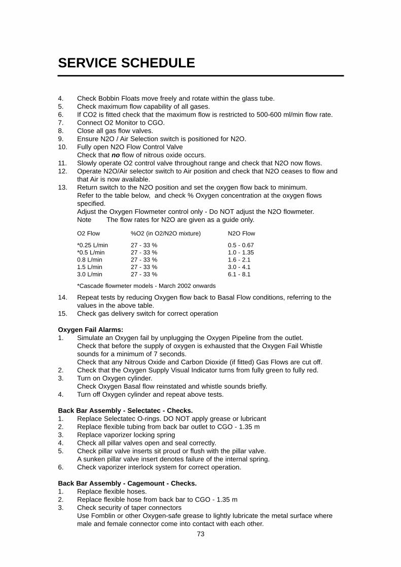
SERVICE SCHEDULE
73
4. Check Bobbin Floats move freely and rotate within the glass tube.5. Check maximum flow capability of all gases.6. If CO2 is fitted check that the maximum flow is restricted to 500-600 ml/min flow rate.7. Connect O2 Monitor to CGO.8. Close all gas flow valves.9. Ensure N2O / Air Selection switch is positioned for N2O.10. Fully open N2O Flow Control Valve
Check that no flow of nitrous oxide occurs.11. Slowly operate O2 control valve throughout range and check that N2O now flows.12. Operate N2O/Air selector switch to Air position and check that N2O ceases to flow and
that Air is now available.13. Return switch to the N2O position and set the oxygen flow back to minimum.
Refer to the table below, and check % Oxygen concentration at the oxygen flowsspecified. Adjust the Oxygen Flowmeter control only - Do NOT adjust the N2O flowmeter.Note The flow rates for N2O are given as a guide only.
O2 Flow %O2 (in O2/N2O mixture) N2O Flow
*0.25 L/min 27 - 33 % 0.5 - 0.67*0.5 L/min 27 - 33 % 1.0 - 1.350.8 L/min 27 - 33 % 1.6 - 2.11.5 L/min 27 - 33 % 3.0 - 4.13.0 L/min 27 - 33 % 6.1 - 8.1
*Cascade flowmeter models - March 2002 onwards
14. Repeat tests by reducing Oxygen flow back to Basal Flow conditions, referring to thevalues in the above table.
15. Check gas delivery switch for correct operation
Oxygen Fail Alarms:1. Simulate an Oxygen fail by unplugging the Oxygen Pipeline from the outlet.
Check that before the supply of oxygen is exhausted that the Oxygen Fail Whistlesounds for a minimum of 7 seconds.Check that any Nitrous Oxide and Carbon Dioxide (if fitted) Gas Flows are cut off.
2. Check that the Oxygen Supply Visual Indicator turns from fully green to fully red.3. Turn on Oxygen cylinder.
Check Oxygen Basal flow reinstated and whistle sounds briefly.4. Turn off Oxygen cylinder and repeat above tests.
Back Bar Assembly - Selectatec - Checks.1. Replace Selectatec O-rings. DO NOT apply grease or lubricant2. Replace flexible tubing from back bar outlet to CGO - 1.35 m3. Replace vaporizer locking spring4. Check all pillar valves open and seal correctly.5. Check pillar valve inserts sit proud or flush with the pillar valve.
A sunken pillar valve insert denotes failure of the internal spring.6. Check vaporizer interlock system for correct operation.
Back Bar Assembly - Cagemount - Checks.1. Replace flexible hoses.2. Replace flexible hose from back bar to CGO - 1.35 m3. Check security of taper connectors
Use Fomblin or other Oxygen-safe grease to lightly lubricate the metal surface wheremale and female connector come into contact with each other.

SERVICE SCHEDULE
74
Fresh Gas Pressure Relief Valve (PRV) Test.1. Occlude CGO with a manometer.2. At 10 L/min Flowrate of Oxygen, the PRV relieves at 41 kPa ± 10%.
Leak Test From Flowmeter to Common Gas Outlet1. Fit a suitable Manometer Test gauge to the CGO.2. Set Oxygen Flow to maintain a pressure of 20 kPa (3 psi).
Maximum permissible flow is 200 ml/min.3. Perform test with and without Vaporizer(s) fitted and with vaporizer(s) turned both ON
and OFF.4 Set oxygen flow to minimum and remove test equipment.
Common Gas Outlet Checks (CGO):1. Check security and freedom of movement of CGO.2. Replace Safelock O-ring. DO NOT apply grease or lubricant3. Check O2 Emergency Flush flowrate is 35 - 75 L/min
Auxiliary Outlets:1. Check outlets for security, damage and correct lock and release movement.2. Check dynamic flowrate and that Oxygen Fail Whistle does not operate.
Oxygen Monitor (if fitted)Function and Calibration Tests.1. Connect a Test O2 Analyser into the patient circuit.2. Check that the machine O2 sensor is inserted into the absorber O2 sampling point.3. Test both O2 sensors in 100% Oxygen.4. Expose both sensors to air and check reading is 21% ± 2.
Adjust high and low O2 alarms and check alarms trigger when values are lower orhigher than reading on O2 analyser respectively. Return the alarm levels to original settings.
5. Restore the sensor to correct location. Remove the test O2 analyser.
Final Gas Concentration Tests.1. Check concentration by Gas.2. Check flowrate from CGO corresponds with flowmeter by concentration.3. Set 3 L/min Oxygen and Nitrous Oxide Flows.
Check, using O2 Monitor that the concentration from the CGO is 50% ± 2%.4. Set Oxygen to 0.5 L/min, set N2O to 0.5 L/min.
Allow O2 monitor to stabilise then check concentration is 50% ± 2%.5. If fitted repeat above test substituting Carbon Dioxide for N2O.6. If fitted set Air to 3 L/min, set Oxygen to 3 L/min.
Check Concentration reading on O2 Monitor is 60% ± 2%.
Test Completion / Paperwork1. Remove all test equipment from machine.2. Drain all Gas from machine.3. Turn OFF Gas Delivery Switch.4. Turn Off all cylinders.5. Turn off all Flow Control Valves.6. Attach Service and Warning Labels.
Penlon recommends that after servicing the Anaesthetic Machine should be given an"Acceptance Check" by an Anaesthetist before being returned to Operational Use.

SERVICE SCHEDULE
75
8.4 Twenty-Four Month Service Checks(To be performed at 24, and 48 Months of a 72-month cycle.)
Machine Frame:1. Check integrity of structure and security of all attachments.2. Check for damage.3. Check wheels for freedom of movement and braking.4. Check drawers, writing tablet move freely.
Electrical Safety Test:1. Check mains lead and plug for damage.2. Perform Electrical Safety Tests as relevant for country of use.3. Check outlet sockets for correct function.
Pipeline Hose Checks:1. Examine pipeline connectors, probes and hoses for cleanliness and damage.2. Perform anti-confusion checks.3. Replace pipeline filters4. Perform pressure Leak Checks of all hoses with cylinders removed and Gas Delivery
Switch in the OFF position.
Cylinder Yoke Assemblies:1. Check for damage, cleanliness, all fittings are tight and clamping screws for freedom
of movement.2. Replace Bodok seals. DO NOT apply grease or lubricant3. Replace yoke inlet filters.
Pressure Gauge and regulator checks:1. Examine all pressure gauges for damage and clarity.2. Check movement of needles is smooth.3. Perform pressure Leak Test of all cylinder Gas Supplies with all Pipelines
disconnected from supply. Perform this test with Gas Delivery Switch turned ON and Oxygen Basal Flowblanked off.
4. For Air / N20 repeat the test with the selector switch in the required position.5. On completion of tests reinstate basal flow by removing test blanking plug.6. Check output pressure of Primary Regulators.7. Check output pressure of Secondary Regulators.
Flowmeter and Mechanical AHD Checks:1. Turn off all cylinders disconnect pipeline hoses and drain all gases from the machine.2. Replace flowmeter tube seals and filters.3. Check Flow Control Valves for smooth operation and positive off position.4. Turn On Gas Delivery Switch
Check Basal Flow of Oxygen is delivered with all Flow Control Valves closed down.All models - up to March 2002 100-200 ml/minCascade O2 flowmeter- March 2002 onwards 50-75 ml/min Single O2 flowmeter - March 2002 onwards 100-200 ml/min
5. Check flow tubes.6. Check Bobbin Floats move freely and rotate within the glass tube.7. Check maximum flow capability of all gases.8. If CO2 is fitted check that the maximum flow is restricted to 500-600 ml/min flow rate.9. Connect O2 Monitor to CGO.10. Close all gas flow valves.

SERVICE SCHEDULE
76
11. Ensure N2O / Air Selection switch is positioned for N2O.12. Fully open N2O Flow Control Valve
Check that NO flow of N2O occurs.13. Slowly operate O2 control valve throughout range and check that N2O now flows14. Operate N2O/Air selector switch to Air position and check that N2O ceases to flow
and that Air is now available.15. Return switch to the N2O position and set the oxygen flow back to minimum.
Refer to the table below, and check % Oxygen concentration at the oxygen flowsspecified . Adjust the Oxygen Flowmeter control only - Do NOT adjust the N2O flowmeter.Note The flow rates for N2O are given as a guide only. O2 Flow %O2 (in O2/N2O mixture) N2O Flow*0.25 L/min 27 - 33 % 0.5 - 0.67*0.5 L/min 27 - 33 % 1.0 - 1.350.8 L/min 27 - 33 % 1.6 - 2.11.5 L/min 27 - 33 % 3.0 - 4.13.0 L/min 27 - 33 % 6.1 - 8.1*Cascade flowmeter models - March 2002 onwards
16. Repeat tests by reducing Oxygen flow back to Basal Flow conditions, referring to thevalues in the above table.
17. Check gas delivery switch for correct operation
Oxygen Fail Alarms:1. Simulate an Oxygen fail by unplugging the Oxygen Pipeline from the outlet.
Check that before the supply of oxygen is exhausted that the Oxygen Fail Whistlesounds for a minimum of 7 seconds.Check that any Nitrous Oxide and Carbon Dioxide (if fitted) Gas Flows are cut off.
2. Check that the Oxygen Supply Visual Indicator turns from fully green to fully red.3. Turn on Oxygen cylinder.
Check Oxygen Basal flow reinstated and whistle sounds briefly.4. Turn off Oxygen cylinder and repeat above tests.
Back Bar Assembly - Selectatec - Checks.1. Replace Selectatec O-rings. DO NOT apply grease or lubricant2. Replace flexible tubing from back bar outlet to CGO - 1.35 m3. Replace vaporizer locking spring4. Check all pillar valves open and seal correctly.5. Check pillar valve inserts sit proud or flush with the pillar valve.
A sunken pillar valve insert denotes failure of the internal spring.6. Check vaporizer interlock system for correct operation.
Back Bar Assembly - Cagemount - Checks.1. Replace flexible hoses.2. Replace flexible hose from back bar to CGO - 1.35 m3. Check security of taper connectors
Use Fomblin or other Oxygen-safe grease to lightly lubricate the metal surface wheremale and female connector come into contact with each other.
Fresh Gas Pressure Relief Valve (PRV) Test.1. Occlude CGO with a manometer.2. At 10 L/min Flowrate of Oxygen the PRV relieves at 41 kPa ± 10%.

SERVICE SCHEDULE
77
Leak Test From Flowmeter to Common Gas Outlet1. Fit a suitable Manometer Test gauge to the CGO.2. Set Oxygen Flow to maintain a pressure of 20 kPa (3 psi).
Maximum permissible flow is 200 ml/min.3. Perform test with and without Vaporizer(s) fitted and with vaporizer(s) turned both ON
and OFF.4 Set oxygen flow to minimum and remove test equipment.
Common Gas Outlet Checks (CGO):1. Check security and freedom of movement of CGO.2. Replace Safelock O-ring. DO NOT apply grease or lubricant3. Check O2 Emergency Flush flow rate is 35 - 75 L/min
Auxiliary Outlets:1. Check outlets for security, damage and correct lock and release movement.2. Check dynamic flowrate and that Oxygen Fail Whistle does not operate.
Oxygen Monitor (if fitted)Function and Calibration Tests.1. Connect a Test O2 Analyser into the patient circuit.2. Check that the machine O2 sensor is inserted into the absorber O2 sampling point.3. Test both O2 sensors in 100% Oxygen.4. Expose both sensors to air and check reading is 21% ± 2.
Adjust high and low O2 alarms and check alarms trigger when values are lower orhigher than reading on O2 analyser respectively. Return the alarm levels to original settings.
5. Restore the sensor to correct location. Remove the test O2 analyser.
Final Gas Concentration Tests.1. Check concentration by Gas.2. Check flowrate from CGO corresponds with flowmeter by concentration.3. Set 3 L/min Oxygen and Nitrous Oxide Flows.
Check, using O2 Monitor that the concentration from the CGO is 50% ± 2%.4. Set Oxygen to 0.5 L/min, set N2O to 0.5 L/min.
Allow O2 monitor to stabilise then check concentration is 50% ± 2%.5. If fitted repeat above test substituting Carbon Dioxide for N2O.6. If fitted set Air to 3 L/min, set Oxygen to 3 L/min.
Check Concentration reading on O2 Monitor is 60% ± 2%.
Test Completion / Paperwork1. Remove all test equipment from machine.2. Drain all Gas from machine.3. Turn OFF Gas Delivery Switch.4. Turn Off all cylinders.5. Turn off all Flow Control Valves.6. Attach Service and Warning Labels.
Penlon recommends that after servicing the Anaesthetic Machine should be given an"Acceptance Check" by an Anaesthetist before being returned to Operational Use.

SERVICE SCHEDULE
78
8.5 Seventy-Two Month Service Checks(To be performed at 72 Months of a 72-month cycle.)
Machine Frame:1. Check integrity of structure and security of all attachments.2. Check for damage.3. Check wheels for freedom of movement and braking.3. Check wheels for freedom of movement, check front braking.4. Check that drawers and writing tablet move freely.
Electrical Safety Test:1. Check mains lead and plug for damage.2. Perform Electrical Safety Tests as relevant for country of use.3. Check outlet sockets for correct function.
Pipeline Hose Checks:1. Examine pipeline connectors, probes and hoses for cleanliness and damage.2. Perform anti-confusion checks.3. Replace pipeline filters4. Replace non-return valve o-rings.5. Perform pressure Leak Checks of all hoses with cylinders removed and Gas Delivery
Switch in the OFF position.
Cylinder Yoke Assemblies:1. Check for damage, cleanliness, all fittings are tight and clamping screws for freedom
of movement.2. Replace Bodok seals. DO NOT apply grease or lubricant3. Replace yoke inlet filters..4. Replace non-return valve O-rings.
Pressure Gauge and regulator checks:1. Examine all pressure gauges for damage and clarity.2. Check movement of needles is smooth.3. Perform pressure Leak Test of all cylinder Gas Supplies with all Pipelines
disconnected from supply. Perform this test with Gas Delivery Switch turned ON and Oxygen Basal Flowblanked off.
4. For Air / N20 repeat the test with the selector switch in the required position.5. On completion of tests reinstate basal flow by removing test blanking plug.6. Check output pressure of Primary Regulators.7. Replace secondary regulators8. Check output pressure of Secondary Regulators.
Flowmeter and Mechanical AHD Checks:1. Turn off all cylinders, disconnect pipeline hoses, and drain all gases from the
machine.2. Replace flowmeter tube seals and filters.3. Check Flow Control Valves for smooth operation and positive off position.4. Turn On Gas Delivery Switch
Check Basal Flow of Oxygen is delivered with all Flow Control Valves closed.All models - up to March 2002 100-200 ml/minCascade O2 flowmeter- March 2002 onwards 50-75 ml/min Single O2 flowmeter - March 2002 onwards 100-200 ml/min

SERVICE SCHEDULE
79
5. Check flow tubes.6. Check Bobbin Floats move freely and rotate within the glass tube.7. Check maximum flow capability of all gases.8. If CO2 is fitted check that the maximum flow is restricted to 500-600 ml/min flow rate.9. Connect O2 Monitor to CGO.10. Close all gas flow valves.11. Ensure N2O / Air Selection switch is positioned for N2O.12. Fully open N2O Flow Control Valve
Check that NO flow of N2O occurs.13. Slowly operate O2 control valve throughout range. Check that N2O now flows14. Operate N2O/Air selector switch to Air position and check that N2O ceases to flow
and that Air is now available.15. Return switch to the N2O position and set the oxygen flow back to minimum.
Refer to the table below, and check % Oxygen concentration at the oxygen flowsspecified . Adjust the Oxygen Flowmeter control only - Do NOT adjust the N2O flowmeter.Note The flow rates for N2O are given as a guide only.
O2 Flow %O2 (in O2/N2O mixture) N2O Flow
*0.25 L/min 27 - 33 % 0.5 - 0.67*0.5 L/min 27 - 33 % 1.0 - 1.350.8 L/min 27 - 33 % 1.6 - 2.11.5 L/min 27 - 33 % 3.0 - 4.13.0 L/min 7 - 33 % 6.1 - 8.1
*Cascade flowmeter models - March 2002 onwards
16. Repeat tests by reducing Oxygen flow back to Basal Flow conditions, referring to thevalues in the above table.
17. Check gas delivery switch for correct operation
Oxygen Fail Alarms:1. Simulate an Oxygen fail by unplugging the Oxygen Pipeline from the outlet.
Check that before the supply of oxygen is exhausted that the Oxygen Fail Whistlesounds for a minimum of 7 seconds.Check that any N2O and Carbon Dioxide (if fitted) Gas Flows are cut off.
2. Check the Oxygen Supply Visual Indicator turns from fully green to fully red.3. Turn on Oxygen cylinder.
Check Oxygen Basal flow reinstated and whistle sounds briefly.4. Turn off Oxygen cylinder and repeat above tests.
Back Bar Assembly - Selectatec - Checks.1. Replace Selectatec O-rings. DO NOT apply grease or lubricant2. Replace flexible tubing from back bar outlet to CGO - 1.35 m3. Replace vaporizer locking spring.4. Check all pillar valves open and seal correctly.5. Check pillar valve inserts sit proud or flush with the pillar valve.
A sunken pillar valve insert denotes failure of the internal spring.6. Check vaporizer interlock system for correct operation.
Back Bar Assembly - Cagemount - Checks.1. Replace flexible hoses.2. Replace flexible hose from back bar to CGO - 1.35 m

SERVICE SCHEDULE
80
3. Check security of taper connectorsUse Fomblin or other Oxygen-safe grease to lightly lubricate the metal surface wheremale and female connector come into contact with each other.
Fresh Gas Pressure Relief Valve (PRV) Test.1. Occlude CGO with a manometer.2. At 10 L/min Flowrate of Oxygen check the PRV relieves at 41 kPa ± 10%.
Leak Test From Flowmeter to Common Gas Outlet1. Fit a suitable Manometer Test gauge to the CGO.2. Set Oxygen Flow to maintain a pressure of 20 kPa (3 psi).
Maximum permissible flow is 200 ml/min.3. Perform test with and without Vaporizer(s) fitted and with vaporizer(s) turned both ON
and OFF.4 Set oxygen flow to minimum and remove test equipment.
Common Gas Outlet Checks (CGO):1. Check security and freedom of movement of CGO.2. Replace Safelock O-ring. DO NOT apply grease or lubricant3. Replace emergency flush valve.4. Check O2 Emergency Flush flow rate is 35 - 75 L/min
Auxiliary Outlets:1. Check outlets for security, damage and correct lock and release movement.2. Check dynamic flowrate and that Oxygen Fail Whistle does not operate.
Oxygen Monitor (if fitted)1 Replace backup battery.
Oxygen Monitor - Function and Calibration Tests.1. Connect a Test O2 Analyser into the patient circuit.2. Check that the machine O2 sensor is inserted into the absorber O2 sampling point.3. Test both O2 sensors in 100% Oxygen.4. Expose both sensors to air and check reading is 21% ± 2.
Adjust high and low O2 alarms and check alarms trigger when values are lower orhigher than reading on O2 analyser respectively. Return the alarm levels to original settings.
5. Restore the sensor to correct location. Remove the test O2 analyser.
Final Gas Concentration Tests.1. Check concentration by Gas.2. Check flowrate from CGO corresponds with flowmeter by concentration.3. Set 3 L/min Oxygen and Nitrous Oxide Flows.
Check, using O2 Monitor that the concentration from the CGO is 50% ± 2%.4. Set Oxygen to 0.5 L/min, set N2O to 0.5 L/min.
Allow O2 monitor to stabilise then check concentration is 50% ± 2%.5. If fitted repeat above test substituting Carbon Dioxide for N2O.6. If fitted set Air to 3 L/min, set Oxygen to 3 L/min.
Check Concentration reading on O2 Monitor is 60% ± 2%.
Test Completion / Paperwork1. Remove all test equipment from machine.

SERVICE SCHEDULE
2. Drain all Gas from machine.3. Turn OFF Gas Delivery Switch.4. Turn Off all cylinders.5. Turn off all Flow Control Valves.6. Attach Service and Warning Labels.
Penlon recommends that after servicing the Anaesthetic Machine should be given an"Acceptance Check" by an Anaesthetist before being returned to Operational Use.
81

82
9.1 Servicing
The Prima SP range of anaestheticmachines must only be serviced by aPenlon-trained engineer to the followingservice schedule:
Every 6 monthsInspection and Function CheckEvery 12 monthsAnnual service which includes routinereplacement of seals, etc. as preventivemaintenanceAt 3 years intervalPipeline hoses - replaceAt 5 years intervalPrimary regulators - replaceEvery 2 and 6 yearsAdditional tests / component replacement
Details of these service operations aregiven in this Prima SP Service Manual,available only to Penlon trained engineers.
Mechanical AHD SystemAdditional servicing for the mechanical AHDsystem only.Function Test (At 6 month intervals, see section 6.8to 6.11) Additional Servicing(At 12 month intervals)Secondary Regulators - check pressuresetting Gear linkage - inspect
Service Tools015067Regulator Spanner - Regulators manufacturedby ‘Gas Arc’
800612Flow setting tool
9.2 Ancillary Equipment9.2.1 Sigma Delta Vaporizer Follow the instructions given in section 8 ofthe user instruction manual. These include:Every 6 monthsFunction test and calibration testEvery 10 yearsMajor overhaul (if unit to be used beyond10 years).Note: Halothane vaporizers - majoroverhaul required at 5 years.On vaporizers with interlock, test thefunction of the interlock system during thevaporizer calibration test.9.2.2 MonitorFollow the service recommendationsdetailed in the monitor user instructionmanual.
9.2.3 AV800 / AV900 VentilatorIf the anaesthetic machine was supplied withan AV-series ventilator, follow theinstructions given in section 7 of the userinstruction manual. These include:
Every 6 monthsInspection and Function Check
Every 12 months (or 1200 hours)Replace bellows
Every 12 monthsReplace O-seals and oxygen inlet filter,etc., as preventive maintenance.
Every 5 yearsReplace batteriesFit service-exchange pneumatic assembly
9.2.4 Anaesthetic GasScavenging SystemFollow the service recommendationsdetailed in the AGSS user instructionmanual.
9.2.5 Circle System AbsorberFollow the service recommendationsdetailed in the circle absorber user instruction manual.
9. SERVICING PROCEDURES

83
9.3 Cleaning and Sterilisation
Frequently wipe over the external surfacesof the machine, the vaporizers, with a dampcloth. Always allow the machine to dry offthoroughly before using it.
(Mild antiseptic solutions may be used butshould be rinsed off with clean water.)
Breathing system hoses and other compo-nents must be sterilised to the manufactur-er’s recommended methods.
MonitorRefer to the monitor user instruction manual.
VentilatorAV-series Ventilator Bellows AssemblyCleaningThe user must follow the detailed instruc-tions included in section 7.5 of the ventilatoruser instruction manual.
Never use any hard object or abrasive agentto clean any of the components, only a softcloth.
If the valve seat is damaged, the diaphragmvalve will leak and this may cause seriousmalfunction. CAUTIONDo not use any cleaning solution containingalcohol or any harsh abrasive cleaning agenton the bellows housing.
SterilisationThe user must follow the detailed instruc-tions included in section 7 of the ventilatoruser instruction manual.WARNINGDo not autoclave the bellows housing. Theexhalation diaphragm valve assembly mustbe disassembled prior to sterilisation - do notsterilise the diaphragm.
SERVICING PROCEDURES

84
1. CGO block2. Auxiliary outlet block3. Reservoir (O2 - for whistle)4. Low pressure block (O2)5. High pressure block (O2)6. Low pressure block (Air)7. High pressure block (Air)8. Low pressure block (N2O)9. High pressure block (N2O)10. High pressure regulator11. Fresh gas pressure relief valve12. Pipeline supply inlet block13. Cut-off valve capsules14. Secondary regulator (O2)15. Secondary regulator (N2O)
16. Secondary regulator (Air)Note: a) Test points are mounted beneath
each secondary regulator.b) On pre-2002 machines, the regu-lators are mounted vertically.
17. Hose from flowmeter18. Fresh gas hose19. O2 flush hose20. Manifold block 21. Test point - primary regulator22. Warning whistle23. Air/N2O interlock switch24. O2 failure visual indicator25. Gas delivery switch
Gas System Components(UK Specification 3-gas machine)
1
3
54
76
19
18
8
9
10
10
11
12
10 21
2121
17
22
23
25
24 1313
14 1516
20
2
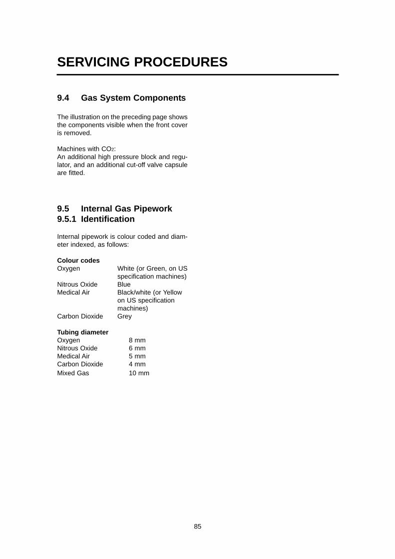
85
9.4 Gas System Components
The illustration on the preceding page showsthe components visible when the front coveris removed.
Machines with CO2:An additional high pressure block and regu-lator, and an additional cut-off valve capsuleare fitted.
9.5 Internal Gas Pipework9.5.1 Identification
Internal pipework is colour coded and diam-eter indexed, as follows:
Colour codesOxygen White (or Green, on US
specification machines)Nitrous Oxide BlueMedical Air Black/white (or Yellow
on US specificationmachines)
Carbon Dioxide Grey
Tubing diameterOxygen 8 mmNitrous Oxide 6 mmMedical Air 5 mmCarbon Dioxide 4 mmMixed Gas 10 mm
SERVICING PROCEDURES

86
9.5.2 Tubing Connectors
Push-in type fittings are used throughout thelow pressure circuit
To connect and disconnect the tubing fromthe connectors, follow the proceduresdetailed below.
Do not use excess force.
Disconnecting tubing from connector
Push in the tube and the connectorend piece ‘A’.
Hold the end piece ‘A’ in place.
Pull the tube out to disconnect.
Fitting tubing to connector
Push in the tube as far as possibleDo not use excessive force.
The connector end piece ‘A’ will also moveinwards.
Pull the tube carefully outwards.The end piece ‘A’ will be pulled outwards tothe ‘locked’ position.
SERVICING PROCEDURES
A
A

87
9.5.3 Cascade FlowmeterAssembly Tubing
The illustration shows the rear of a three-gasflowmeter assembly, with cascade oxygenand nitrous-oxide flowmeter assemblies, asfitted to a UK specification machine withmechanical AHD.
1. Oxygen supply
2. Oxygen - low flow tube to high flowtube
3. Nitrous oxide - supply to primaryneedle valve
4. Nitrous oxide - link to secondaryneedle valve (mechanical AHD)
5. Nitrous oxide - low flow tube to highflow tube
6. Air - supply to flowmeter needle valve
7. Mixed gas supply to backbarmanifold.
SERVICING PROCEDURES
1
4
6
3
25 7

88
9.6 Front Cover - Remove and Refit
CAUTIONEnsure that any residual gas in the machine is exhaustedbefore commencing the dismantling procedure.Removal1. Remove all cylinders, and disconnect Pipeline
supply hoses.2. At the rear of the machine, slacken the screws
(1) securing the gas blocks. 3. Remove the two top fixing screws (2) securing
the panel to the front of the machine.4. Slacken each screw (3) on the side of the
machine, to loosen the side clamp plates.5. Carefully pull the cover (4) away from the front of
the machine.
Refit6. Line up the cover with the gauges and switches.7. Check that the clamp plate on each side of the
machine is positioned to allow the sides of thecover to fit between each plate and the frame.
8. Carefully push the cover into place.9. Screw in the top fixings (2). Do NOT tighten.10. Tighten the clamp plate screws (3).11. Tighten the top fixings (2).12. At the rear of the machine, tighten the screws (1)
SERVICING PROCEDURES
1
2
4
3

89
9.7 Flowmeter Cover
Removal 1. Slacken the screws (1) securing the
filler strip (2).2. Remove the screws (3) and top
guard (4).3. Remove the cover (5).
Refitting4. Reverse the removal procedure.
SERVICING PROCEDURES
2
1
43
5

9.8 Mechanical AHD System
9.8.1 Check and Adjust Basal Flow
All models - up to March 2002Oxygen basal flow 100-200 ml/min
Cascade flowmeter models - March 2002 onwardsOxygen basal flow 50-75 ml/min
Single flowmeter models - March 2002 onwardsOxygen basal flow 100-200 ml/min
NOTE: The machine must be on a flat surface.
1. Check that all flowmeter controls are OFF.
2. Switch the gas delivery switch (1) to ON.
3. Check that a basal flow of oxygen is indicated, asshown above.If the basal flow is outside the range givenabove:a) adjust the output of the secondary Oxygenregulator, (see section 9.11) to achieve thecorrect basal flow.b) check the oxygen concentration, see section9.8.2.
4. Switch the Gas Delivery switch to OFF.
5. If the correct basal flow can not be achieved,reset the gear linkage - see section 9.8.3.
1
SERVICING PROCEDURES
90

SERVICING PROCEDURES
91
9.8.2 Check Oxygen ConcentrationNOTE: The machine must be on a flat surface.
1. If the machine is not fitted with an Oxygen monitor, connecta stand-alone analyser to the CGO outlet.
2. Set the Gas Delivery switch (1) to ON.
3. Turn the Nitrous Oxide flowmeter control to maximum.
4. Refer to the table below, and check % Oxygen concentrationat the oxygen flows specified . Adjust the Oxygen Flowmeter control only - Do NOTadjust the N2O flowmeter.Note The flow rates for N2O are given as a guide only.
O2 Flow %O2 (in O2/N2O mixture) N2O Flow
*0.25 L/min 27 - 33 % 0.5 - 0.67*0.5 L/min 27 - 33 % 1.0 - 1.350.8 L/min 27 - 33 % 1.6 - 2.11.5 L/min 27 - 33 % 3.0 - 4.13.0 L/min 27 - 33 % 6.1 - 8.1
*Cascade flowmeter models - March 2002 onwards
If the %O2 concentration is outside the range givenabove, at any of the set flows, adjust the output ofeither or both of the secondary regulators (oxygen - 2)(nitrous oxide - 3), as follows:
5. Switch the Gas Delivery switch to OFF.
6. Remove the front cover - follow the procedure given insection 9.6.Retighten the screws (5) securing the gas blocks.Reconnect the cylinder and pipeline supplies.
7. Attach a pressure gauge to the regulator test point (4).
8. Switch the Gas Delivery switch to ON.
9. To increase output: turn the regulator cap, (2 or 3) slowlyclockwise.To decrease output: turn the regulator cap fully anti-clock-wise, then clockwise to the correct setting.Maintain the output pressure within the ranges:
All models - up to March 2002Secondary regulator pressure 207 - 283 kPa (30 - 41 psi)
All models - March 2002 onwardsSecondary regulator pressure 152 - 241 kPa (22 - 35 psi)
10. If the correct basal flow can not be achieved, reset the gearlinkage - see section 9.8.3.
11. Recheck the Oxygen Concentration.
1
32
4
5
NOTE:Early type regulatorsshown in illustration

9.8.3 Gear Linkage - Reset Cascade and Single Flowmeter Tube SystemsMarch 2002 Onwards
NOTE: The machine must be on a flat surface.
Set the secondary regulators1. Set the Gas Delivery Switch to OFF.2. Disconnect all pipeline and cylinder supplies.3. Remove the front cover - see section 9.6.
Retighten the screws securing the gas blocks.Reconnect the cylinder and pipeline supplies.
4. Attach a pressure gauge to the oxygen regulator test point (1).(Early type regulators shown in illustration)
5. Set the Gas Delivery Switch to ON.
6. Set a flow of 5 L/min Oxygen.Reset the O2 secondary regulator to 172 kPa (25.0 psi).
7. To increase output: turn the regulator cap, (3) slowly clockwise.To decrease output: turn the regulator cap fully anti-clockwise,then clockwise to the correct setting.
8. Return the flow to minimum.9. Attach a pressure gauge to the N2O regulator test point (2).
10. Set a flow of 5 L/min nitrous oxide.Reset the N2O secondary regulator to 186 kPa (27.0 psi).To increase output: turn the regulator cap, (3) slowly clockwise.To decrease output: turn the regulator cap fully anti-clockwise,then clockwise to the correct setting.Return the flow to minimum.
11. Set the Gas Delivery Switch to OFF.
Gear Linkage12. Remove the flowmeter control knobs (4), screws (5) and control
knob cover (6).
13. Loosen the grubscrews and remove the O2 gear (7) and smallN2O gear (8).
14. Check the condition of the gears and grubscrews. Replace withnew components if necessary.Clean all traces of Loctite from the grubscrews and apply newLoctite 242.
15. Check that each gear slides easily on its shaft.
16. Set the Gas Delivery Switch to ON.17. Open the N2O valve to maximum, to check full flow.
18. Close the valve gently until the N2O bobbin ceases to rotate.Do not over tighten the valve when closing - this will causeirreparable damage to the valve seat.
19. Fit the O2 gear (7) on the shaft.Fit the Setting Tool (9). Part No. 800612.
4
4 65
5
3
21
8
7
9
SERVICING PROCEDURES
92

20. Fit the O2 control knob and open the O2 control valve, tocheck full flow.Cascade Flowmeter Tube Models:Close the valve until a flow of 50-75 ml/min is obtained.Single Flowmeter Tube Models:Close the valve until a flow of 100-200 ml/min is obtained.
21 Distance the inner face of the O2 gear with a 0.1 mm feelergauge at ‘A’. Tighten the grubscrews.Check the flow returns to the basal flow set in operation 20,above.
22. Refit the N2O gear (8) - be careful not to move either shaft. Tighten the grub screws.
23. Apply a small amount of BG 87 to the gears.
24. If the machine is not fitted with an Oxygen monitor, connecta stand-alone analyser to the CGO outlet.
25. Check Oxygen concentration:
26. Turn the Nitrous Oxide flowmeter control to maximum.Refer to the table below, and check % Oxygen concentrationat the Oxygen flows specified . Adjust the Oxygen Flowmeter control only - Do NOTadjust the N2O flowmeter.Note The flow rates for N2O are given as a guide only.
O2 Flow %O2 (in O2/N2O mixture) N2O Flow
*0.25 L/min 27 - 33 % 0.5 - 0.67*0.5 L/min 27 - 33 % 1.0 - 1.350.8 L/min 27 - 33 % 1.6 - 2.11.5 L/min 27 - 33 % 3.0 - 4.13.0 L/min 27 - 33 % 6.1 - 8.1
*Cascade flowmeter models - March 2002 onwards
If the %O2 concentration is outside the range givenabove, at any of the set flows, adjust the output ofeither or both of the secondary regulators - see 9.8.2.
NOTE Maintain output pressures within the range:152 - 241 kPa (22 - 35 psi)
27. Check the Oxygen basal flow - see 9.8.1.28. Recheck the Oxygen Concentration.29. Remove the O2 control knob and the Setting Tool (9).30. Carefully refit the control knob cover (6) and screws (5),
ensuring that the basal flow does not change.Fit the O2 and N2O control knobs.
9
65
5
A
8
SERVICING PROCEDURES
93

94
9.8.4 Gear Linkage - Reset(Models built up to Feb 2002
CAUTIONEnsure that any residual gas in the machine isexhausted before commencing the dismantling pro-cedure.Removal1. Remove all cylinders, and disconnect
Pipeline supply hoses.2. Remove the two screws (1) and control
knob cover (2).3. Check the condition of the gears and
grubscrews, and replace if necessary.4. To reset the gears, first remove the O2
gear (4) only.5. Turn the Gas Delivery switch (5) to On.
Gently close the N2O primary valve sothat the N2O flowmeter bobbin reseats.NOTEa) This valve is closed by turning the
needle anti-clockwise.b) On machines with Air, set the
Air/N2O interlock switch (6) to N2O).
6. Set the oxygen control valve so that abasal flow of 150 ml/min of oxygen issupplied.
7. Remove the N2O gear (7).Carefully replace the O2 gear so that thegear stop (8) is positioned anti-clock-wise, and just touching the mechanicalstop (9) in the front of the manifold block(see illustration).
8. Distance the inner face of the O2 gearfrom the mechanical stop with a 0.1 mmfeeler gauge.Tighten the grubscrews (10) to securethe O2 gear.
9. With the O2 gear against the stop,replace the N2O gear and push on sothat the front faces of the gears are flush,see X-X as illustrated. Note that the rear face of the N2O gear iscloser to the manifold block than the O2
gear.
Tighten the grubscrews (11) to securethe N2O gear.Apply a small amount of Molycote BG87grease, evenly distributed, to the O2 andN2O gear teeth.
SERVICING PROCEDURES
12
3
5
6
7
X
X
4
810
11
9
0.1 mm

95
Gas Flow10. Check the gas flows. See Function Test,
section 6.7.11. If the gas flows are inaccurate, small
adjustments can be made by adjusting theoxygen basal flow within the range 150 -200 ml, and then using the secondary reg-ulators, as follows.
12. Attach a pressure gauge to the test pointon each regulator (12 - oxygen, 13 -nitrous oxide). At 5 L/min flow both regulators should beset at 275 kPa (40 psi), but adjustment isavailable from 261 to 289 kPa (35 to 41psi).
13. If the N2O flow is low the N2O pressureshould be increased to 289 kPa (41 psi),before the O2 pressure is reduced to 261kPa (35 psi).
14. Similarly, if the N2O flow is high, the O2
pressure should be increased, before theN2O pressure is reduced.
15. Carry out a full function test on themachine, see section 6.
SERVICING PROCEDURES
1213
Note: On machines built from March 2002,the regulators are mounted horizontally
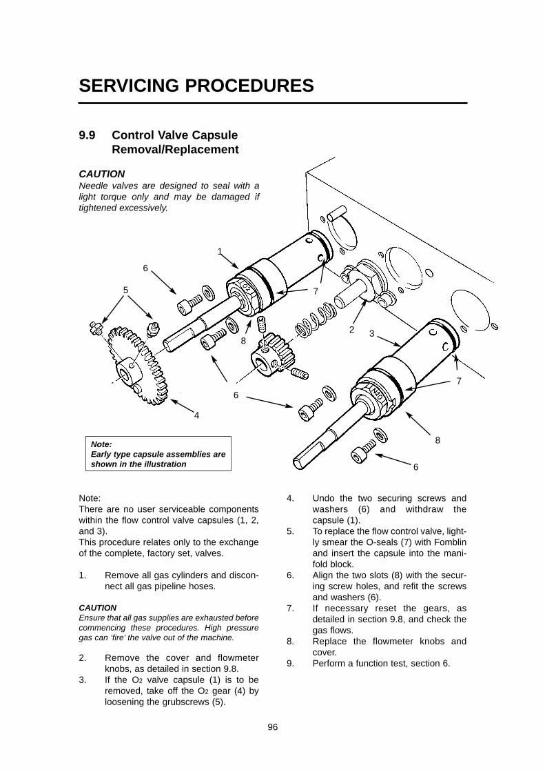
5
6
6
6
8
8
7
7
1
32
4
96
Note:There are no user serviceable componentswithin the flow control valve capsules (1, 2,and 3). This procedure relates only to the exchangeof the complete, factory set, valves.
1. Remove all gas cylinders and discon-nect all gas pipeline hoses.
CAUTIONEnsure that all gas supplies are exhausted beforecommencing these procedures. High pressuregas can ‘fire’ the valve out of the machine.
2. Remove the cover and flowmeterknobs, as detailed in section 9.8.
3. If the O2 valve capsule (1) is to beremoved, take off the O2 gear (4) byloosening the grubscrews (5).
4. Undo the two securing screws andwashers (6) and withdraw thecapsule (1).
5. To replace the flow control valve, light-ly smear the O-seals (7) with Fomblinand insert the capsule into the mani-fold block.
6. Align the two slots (8) with the secur-ing screw holes, and refit the screwsand washers (6).
7. If necessary reset the gears, asdetailed in section 9.8, and check thegas flows.
8. Replace the flowmeter knobs andcover.
9. Perform a function test, section 6.
SERVICING PROCEDURES
9.9 Control Valve Capsule Removal/Replacement
CAUTIONNeedle valves are designed to seal with alight torque only and may be damaged iftightened excessively.
Note:Early type capsule assemblies areshown in the illustration

97
9.10 Oxygen Reservoir - Removal/Replacement
1. Remove all oxygen cylinders and dis-connect the oxygen pipeline hose.
CAUTIONEnsure that any residual gas in the machine isexhausted before commencing the dismantlingprocedure.
2. Remove the cover at the back of themachine to gain access to the rear ofthe flowmeter assembly.
3. Unscrew the nut (1) to release theoxygen reservoir (2) from the mount-ing bracket.
4. After refitting, perform a function test,section 6.
SERVICING PROCEDURES
1
2
Note:Early type reservoir isshown in the illustration

Note:Early type regulators areshown in the illustration
98
SERVICING PROCEDURES
9.11 Secondary RegulatorsCheck and Reset PressureOutput
1. Turn the Gas Delivery Switch to OFF.
2. Disconnect all pipeline and cylindersupplies
3. Remove the front cover - see section9.6.Retighten the screws securing the gasblocks.Reconnect the cylinder and pipelinesupplies.
4. Attach a pressure gauge to the oxygenregulator test point (1).(Early type regulators shown inillustration)
5. Turn the Gas Delivery Switch to ON.
6. Set a flow of 5 L/min Oxygen.Reset the Oxygen secondary regulatorto the figure given in the table.
7. To increase output: turn the regulatorcap, (2) slowly clockwise.To decrease output: turn the regulatorcap fully anti-clockwise, then clockwiseto the correct setting.
8. Return the flow to minimum.
9. Attach a pressure gauge to the nitrousoxide regulator test point (3).
10. Set a flow of 5 L/min nitrous oxide.Reset the N2O secondary regulator tothe figure given in the table.To increase output: turn the regulatorcap, (4) slowly clockwise.To decrease output: turn the regulatorcap fully anti-clockwise, then clockwiseto the correct setting.Return the flow to minimum.
11. Turn the Gas Delivery Switch to OFF.
12. Check the oxygen basal flow - seesection 9.8.1.
13. Check % oxygen concentration. - seesection 9.8.2.
3
42
1
Secondary regulatorsPressure output at 5 L/min flow
Machines built from March 2002 onwardsOxygen and Nitrous Oxide 152 - 241 kPa (22 - 35 psi)
Air 207 - 283 kPa (30 - 41 psi)
Machines built before March 2002All gases 207 - 283 kPa (30 - 41 psi)

99
9.12 High Pressure (Cylinder)Gas BlockRemove and Refit
CAUTIONEnsure that any residual gas in the machine isexhausted before commencing the dismantlingprocedure.
1. Remove all cylinders and disconnectall pipeline supplies.
2. At the rear of the machine, remove thetwo screws (1) at the rear of the blockto be removed.Refer to 9.6.2 if necessary.
3. Remove the screws (2) at the rear ofthe adjacent gas block.
4. At the front of the machine, carefullypull the blocks (3 and 4) from themachine.Separate the blocks - detach the block(4) from the tubing connector (5).
5. To refit. reverse the above procedureand then carry out a full function test(see section 6).
Yoke Filter - Remove and RefitCAUTIONEnsure that any residual gas in the machine isexhausted before commencing the dismantlingprocedure.
1. Remove all cylinders and disconnectall pipeline supplies.
2. remove the Bodok seal (1).3. Unscrew the yoke insert (2).4. Use a suitable rod to carefully remove
the filter (3).5. To refit. reverse the above procedure.
Fit a new Bodok seal.Function test the machine (see sec-tion 6).
SERVICING PROCEDURES
1 2
3
3
2
1
45

100
SERVICING PROCEDURES
OverhaulCAUTION Ensure that any residual gas inthe machine is exhausted beforecommencing the dismantling procedure.
Removal1. Remove all cylinders and
disconnect all pipeline supplies.2. Remove the front cover, (see
section 9.6), to gain access to themanifold block.
3. Disconnect the inlet and outletfresh gas hoses.
4. Remove the screws at the rear ofthe machine, to allow removal ofthe manifold block.
Overhaul and Refit5. Dismantle the block as illustrated.
Note that later Prima SP modelsare fitted with a one-piecemanifold block assembly.
6. Renew all O-seals.7. To refit. reverse the dismantling
procedure.Function test the machine - seesection 6.
9.13 Selectatec CompatibleManifold Block
1. The valve capsule top O-seal(arrowed on the illustration) mustbe regularly changed to preventthe possible occurrence of leakingCheck for splitting, perishing, andexpansion, and also check if theseal is sticking to the vaporizer.
To ensure satisfactory performance:a. ALWAYS perform a leak test
before using the manifold block orafter changing the vaporizer.
b. Replace these O-seals regularly(maximum 6 months interval).DO NOT apply grease or lubricant
One-piece manifold block- fitted to later Prima SP models

101
9.14 Gas Delivery Switch
CAUTIONEnsure that any residual gas in the machine isexhausted before commencing the dismantlingprocedure.1. Remove all cylinders and disconnect
all pipeline supplies.2. Remove the front cover (see 9.6).3. Remove the cover at the back of the
machine4. Remove the screws (1) to release the
switch mounting bracket (2).5. Disconnect the tubing from the rear of
the switch assembly (3). 6. Slacken the screws (4).7. Twist the front of the switch, as illus-
trated, to unlock the two halves of theswitch assembly.
Refitting8. Reverse the removal procedure.
Fit the front cover - see section 9.6.Carry out a Function test, section 6.
SERVICING PROCEDURES
34
1
12

102
9.15 Air/N2O Interlock SwitchCAUTIONEnsure that any residual gas in the machine is exhausted beforecommencing the dismantling procedure.
1. Remove all cylinders and disconnect all pipelinesupplies.
2. Remove the front cover (see 9.6).3. Disconnect the tubing from the switch assembly (1). 4. Remove the cover at the back of the machine5. Remove the screws (2) to release the switch
mounting bracket (3).6. Turn the lever (4) clockwise to unlock the two
halves of the switch assembly. 7. Unscrew the locking ring (5), and detach the toggle
switch (6).Refitting8. Reverse the removal procedure.
Align the toggle switch (6) as illustrated.Fit the front cover - see section 9.6.
Carry out a Function Test, section 6.
SERVICING PROCEDURES
Turn this wayto remove
Align, as illustrated
2
1
32
4
5

103
9.16 Oxygen Failure Visual Indicator
CAUTIONEnsure that any residual gas in the machine is exhaust-ed before commencing the dismantling procedure.
Removal1. Remove all cylinders and disconnect all
pipeline supplies.2. Remove the front cover (see 9.6).3. Disconnect the tubing at the rear of the
visual indicator (1). 4. Remove the cover at the back of the
machine5. Remove the screws (2) to release the
switch mounting bracket (3).6. Unscrew the locking ring (4), and detach
the visual indicatorRefitting8. Reverse the removal procedure.
Fit the front cover - see section 9.6.Carry out a Function test, section 6.
SERVICING PROCEDURES
2
2
1
3
4

104
9.17 CGO Block- Clippard Valve Replacement
CAUTIONEnsure that any residual gas inthe machine is exhausted beforecommencing the dismantlingprocedure.
Removal1. Remove all cylinders
and disconnect allpipeline supplies.
2. Depress the button (1)to allow access at (2)to the grubscrew thatretains the button.
3. Slacken the grubscrew,using a M1.3 Allen key,and gently prise out thebutton.
4. Remove the two screws (3), and withdrawthe shield (4), valve (5) and O seal (6).
Refitting5. Lightly coat the seal (6) with Fomblin.6. Reverse the removal sequence.
Carefully refit the Clippard Valve (5) toprevent damage to the seals.Check that the countersunk screw andlocating screw (3) are fitted in the correctorientation, as illustrated
7 Carry out a machine function check - section6.
SERVICING PROCEDURES
1
2
3
3
456

105
SERVICING PROCEDURES
9.18 Flowmeter Tubes - Removal
CAUTION Ensure that any residual gas in themachine is exhausted before commencing the dis-mantling procedure.
Removal1. Remove all cylinders and disconnect all
pipeline supplies.2. Remove the flowmeter cover, (see section
9.7).3. Hold the tube, as illustrated, and press
upwards (X) against the resistance of thespring.
4. Carefully detach the lower end of the tubefrom the bobbin.
5. Remove the tube, ensuring that the topbobbin remains in place (Y).
Overhaul - Bobbin Assemblies6. Remove and refit the components, as illus-
trated below, taking care not to damage theO-seals when refitting the bobbins.
Refitting the Flowmeter7. Reverse the removal procedure, noting:
a) the scale must be centralised.b) the tube is touching the contact strip (1).
8. Carry out a machine Function Test - sec-tion 6.
0293O-seal
400262Bobbin
400224Bobbin
0508 Filter
0293O-seal
0691O-seal
0691O-seal
36075Washer
01057Washer
36247Bobbin
36247Bobbin
X
Y
1
Cascade flowmeter system illustrated.On non-cascade models, a filter (0508)is fitted to each flow tube.

106
9.19 Flowmeter Assembly - Removal
CAUTIONEnsure that any residual gas in the machine isexhausted before commencing the dismantlingprocedure.
Removal1. Remove all cylinders and disconnect
all pipeline supplies.2. Disconnect the machine from the
mains electrical supply (if necessary).3. Remove the flowmeter cover, (see
section 9.7).4. Remove the four screws (1) securing
the flowmeter assembly to themachine frame.
5. Disconnect the wiring connector (2) -machines with flowbank lighting only.
6. Disconnect the tubing (3) where nec-essary to allow the removal of theflowmeter assembly.
Refitting7. Reconnect the tubing at the back of
the flowmeter assembly - see section9.5.
8. Reverse the removal procedure.9. Carry out a machine Function Test -
section 6.
SERVICING PROCEDURES
1
3
2
3

107
SERVICING PROCEDURES
9.20 Flowmeter Lighting - Removal
CAUTIONEnsure that any residual gas in the machine isexhausted before commencing the dismantlingprocedure.
Removal1. Remove all cylinders and disconnect
all pipeline supplies.2. Disconnect the machine from the
mains electrical supply.3. Remove the flowmeter cover, (see
section 9.7).4. Remove the flowmeter tubes and
flowmeter assembly (see sections9.18 and 9.19).
5. Disconnect the tubing connector (1).6. Remove the three screws (2), and
detach the manifold (3).7. Remove the lighting assembly (4).
Refitting8. Reverse the removal procedure.
Refer to section 9.5 for tubing connec-tions.
9. Carry out a machine Function Test,see section 6.
1 2
34

108
SERVICING PROCEDURES
9.21 Oxygen Monitor - Battery Replacement
Removal1. Disconnect the machine from the
mains electrical supply.2. Remove the four screws (1).3. Carefully detach the front cover
assembly (2), to allow access to thebattery (3).
4. The battery is attached to the sidepanel with an adhesive pad.Disconnect the battery wiring anddetach the battery and pad.
Refitting5. Reverse the removal procedure.
Carry out a machine function test -section 6.
1
1
2
3

9.22 Oxygen Monitor Sensor.
Sensor - Cleaning and Disinfection
CAUTIONIf you use ethylene oxide for sterilisation, use only a lowtemperature ethylene oxide method. Do not immerse thesensor in any cleaning solution. Do not autoclave or expose the sensor to high temperatures.
Sensor ReplacementWARNINGThe sensor contains:a) A small quantity of electrolyte, classified as a harmfulirritant which is potentially hazardous. b) LeadDo not attempt to open a cell. ALWAYS check the integrity of the sensor assembly beforeuse.Once exhausted, the sensor must be disposed of according tohospital, local, state and federal regulations.
Sensor Expiry DateThe approximate expiry date is marked on the sensor label,using two boxes which represent the year and month. Thus, for a sensor marked as below, the approximate expirydate is end of December 2004.
YR 0 1 2 3 4 5 6 7 8 9
MTH J F M A M J J A S O N D
Sensor Unit - Remove and Refit
1. Pull out the cable connector (A) from the expiredsensor (B).
2. Remove sensor from the absorber or Tee adaptor.3. Discard the expired sensor and flow diverter (C).4. Insert the cable connector into the new sensor (B).5. Screw the new flow diverter (C) onto the new sensor,
and fit new O rings.6. Fit the assembly into the Tee adaptor or absorber.7. Reconnect the cable8. Calibrate the new sensor, see section 5.12.9. Dispose of the used components according to hospital
regulations and relevant national legislation.
xx
109
SERVICING PROCEDURES
Replacement parts102714 Sensor (B)
(includes flow diverter (C) and O rings)58779 Tee adaptor (CGO fitting)
A
C
B
Sensor
Oxygen Sensor Location
1. Prima SP with A100SP Absorber
2. Mounted on the dome of theabsorber inspiratory valve
3. ‘T’ piece adaptor on CGO block

110
9.23 A100 Circle System AbsorberFollow the user maintenance procedures and servicerecommendations detailed in the A100 circle absorber userinstruction manual.
Inboard Mounting System on Prima SP- access to theCanister and Valve Block
Absorber Canister Absorber ValveBlock AssemblyRemoval
Remove1. Slide the canister and sup-
port plate out from themachine.
2. Disconnect the hoses.Rotate the retainer (A), andsupport the canister as it isremoved from the machine.
1. Lift the retainingpin (C).Disconnect thehoses.Support theweight of thevalve block as itis removed fromthe machine.
A
C
Refit1. Align the buttons (B) on the top of
the canister block with the slotsin the support plate.
2. Slide the canister into the supportplate, and rotate the retainer (A)to lock the canister in position.
3. Reconnect the hoses (see 5.6.4),Slide the canister and supportplate under the machine worksurface.
Refit1. Align the buttons
(D) on the top ofthe canister blockwith the slots (E).
2. Slide the canisterinto the supportplate.
3. Reconnect thehoses (see 5.6.4).
4. Fit the retaining pin(C).
B
D
A
SERVICING PROCEDURES
NoteFor A100SPAbsorber, seeAppendix 4

111
Part No. DescriptionPrima SP Mechanical AHD and Selectatec57455 6 month57476 12 month57479 24 month57476 36 month57479 48 month57476 60 month57490 72 month
Prima SP Mechanical AHD andCagemount Backbar57455 6 month58614 12 month57480 24 month58614 36 month57480 48 month58614 60 month57489 72 month
A100 Absorber58615 12 month58609 60 month
AV900 Ventilator57453 12 month57453 24 month57453 36 month57453 48 month57454 60 month
AV800 Ventilator57633 12 month57633 24 month57633 36 month57633 48 month57635 60 month
Nuffield 200 Ventilator57139 12 month57139 24 month57139 36 month57139 48 month57450 60 month
Circle System Module57451 12 month57451 24 month57451 36 month57451 48 month57452 60 month
Delta Vaporizer Overhaul Kits55146 5 year Halothane -
Pour Filler55145 Halothane - Agent Specific
(Key) Filler55144 10 year Enflurane -
Pour Filler55143 10 year Enflurane -
Agent Specific (Key) Filler55142 10 year Isoflurane -
Pour Filler55141 10 year Isoflurane -
Agent Specific (Key) Filler55140 10 year Sevoflurane -
Pour Filler 55139 10 year Sevoflurane -
Agent Specific (Key) Filler55147 10 year Sevoflurane -
Quik Fil Filler
10. PARTS LIST
Prima SP System - Preventive Maintenance Kits

Preventive Maintenance Kit6 Month Service (use also for UK customer specified 3 month service)
Part No. 57455
Kit ContentsPart No Qty. Component Description016 5 Bodok Seal041115 6 O-ring - Selectatec043 1 O-ring - Safelock Connector on CGO Block
WARNING Do NOT apply grease or lubricant
041115O-ring
016Bodok Seal
043O-ring
PARTS LIST
112

113
PARTS LIST
0226O-sealOffline
Hose016 BodokSeal
0762 Filter - Yoke
0762 Filter - Pipeline
37950 OfflineHose
0226O-seal
462526Hose -
Backbarto CGO
043O-seal- Safelock
Cagemount BackbarPreventive Maintenance Kit12 / 36 / 60 Month ServicePart No. 58614
Kit ContentsPart No Qty. Component Description462526 1.35 m Hose - Backbar Outlet to CGO
(not shown)37946 12 Hose Support37947 12 Seal Support37951 12 Split Ring37950 4 Off-line Hose016 5 Bodok Seal0762 8 Filter - Yoke and Pipeline043 1 O-seal - Safelock0226 12 O-seal - Hose Assembly011017 1 Tubing - Sample Block
37946Hose Support
37947Seal Support37951
Split Ring
Do NOT apply greaseor lubricant to:016, Bodok Seal043, O-seal - Safelock

114
PARTS LIST
Cagemount BackbarPreventive Maintenance Kit24 / 48 Month ServicePart No. 57480
Kit ContentsPart No Qty. Component Description462526 1.35 m Hose - Backbar Outlet to CGO37950 4 Off-line Hose016 5 Bodok Seal400224 3 Flowmeter Bobbin - Metal with Filter400262 3 Flowmeter Bobbin - Metal with Filter0762 8 Filter - Yoke and Pipeline0508 3 Filter - Flowmeter36247 6 Flowmeter Bobbin - Tube Seals01057 3 Washer36075 6 Shock Washer0691 6 O-seal - Flowmeter043 1 O-seal - Safelock0226 12 O-seal - Hose Assembly37946 12 Hose Support37947 12 Seal Support37951 12 Split O-ring011017 1 Tubing - Sample Block
0226O-seal
Offline Hose
016 BodokSeal
0762 Filter - Yoke
0762 Filter - Pipeline
37950 OfflineHose
37946Hose Support
37947Seal Support
37951Split Ring
Do NOT apply greaseor lubricant to:016, Bodok Seal043, O-seal - Safelock

115
PARTS LIST
0226O-seal
0226O-seal
462526Hose - Backbar
Outlet to CGO
043O-seal- Safelock
0293O-seal
400262Bobbin
400224Bobbin
0508 Filter
0293O-seal
0691O-seal
0691O-seal
36075Washer
01057Washer
36247Bobbin
36247Bobbin
Cascade flowmeter system illustrated. On non-cascade models, a filter (0508) is fitted to eachflow tube.

116
PARTS LIST
37946Hose Support
37947Seal Support37951
Split Ring
Cagemount BackbarPreventive Maintenance Kit72 Month ServicePart No. 57489
Kit ContentsPart No Qty. Component Description462526 1.35 m Hose - Backbar Outlet to CGO0226 4 O Seal - Hose Assembly37946 4 Hose Support37947 4 Seal Support37951 4 Split Ring37950 4 Off-Line Hose016 5 Bodok Seal400224 3 Flowmeter Bobbin - Metal with Filter400262 3 Flowmeter Bobbin - Metal withoutFilter0762 8 Filter - Yoke and Pipeline0508 3 Filter - Flowmeter36247 6 Flowmeter Bobbin - Tube Seals01057 4 Washer36075 6 Shock Washer0691 6 O Seal - Flowmeter
043 1 O Seal - Safelock011017 1 Tubing - Sample Block045438 2 Secondary Regulators - Mech AHD90183 1 Clippard Valve - Oxygen Flush0314 2 O Ring - Oxygen Flush Clippard
Valve0691 6 O Ring - Cylinder/Pipeline NRVFollowing not shown:462544 3 m 8 mm Hose - Oxygen - Internal462543 2 m 6 mm Hose - Nitrous Oxide - Internal462542 2 m 5 mm Hose - Air - Internal462541 1 m 4 mm Hose - Switch Feeds/CO2 -
Internal01089 1strip Gas ID Label White - Oxygen011026 1strip Gas ID Label Blue - Nitrous Oxide011027 1strip Gas ID Label Black - Air011023 1strip Gas ID Label Grey - Carbon Dioxide
016 Bodok Seal
90183Clippard Valve
0314O-ring 0762
Filter - Yoke
0762 Filter - Pipeline
0226O-seal
Offline Hose
37950 OfflineHose
Do NOT apply greaseor lubricant to:016, Bodok Seal043, O-seal - Safelock

117
PARTS LIST
0293O-seal
400262Bobbin
400224Bobbin
0508 Filter
0293O-seal
0691O-seal
0691O-seal
36075Washer
01057Washer
36247Bobbin
36247Bobbin
Cascade flowmeter system illustrated. On non-cascade models, a filter (0508) isfitted to each flow tube.
0226O-seal462526 Hose
- Backbar Outletto CGO
043O-seal
0691O-ring
0691O-ring
045438Secondary Regulators
0691O-seal

118
PARTS LIST
Selectatec BackbarPreventive Maintenance Kit12 / 36 / 60 Month ServicePart No. 57476
Kit ContentsPart No Qty. Component Description462526 1.35 m Hose - Backbar Outlet to CGO37946 4 Hose Support37947 4 Seal Support37951 4 Split Ring022533 2 Dzus Clip041115 4 O-ring - Selectatec016 5 Bodok Seal0762 8 Filter - Yoke and Pipeline043 1 O-seal - Safelock011017 1 Tubing - Sample Block
022533Dzus Clip
041115O-ring
016 Bodok Seal
0762 Filter - Yoke
0762 Filter -Pipeline
0226O-seal
462526Hose - Backbar
Outlet to CGO
043O-seal- Safelock
Do NOT apply grease orlubricant to:016, Bodok Seal043, O-seal - Safelock041115, O-ring -Selectatec

119
PARTS LIST
Selectatec BackbarPreventive Maintenance Kit24 / 48 Month ServicePart No. 57479
Kit ContentsPart No Qty. Component Description462526 1.35 m Hose - Backbar Outlet to CGO37946 4 Hose Support37947 4 Seal Support37951 4 Split Ring041115 4 O-ring - Selectatec016 5 Bodok Seal400224 3 Flowmeter Bobbin - Metal with Filter400262 3 Flowmeter Bobbin - Metal without Filter0762 8 Filter - Yoke and Pipeline0508 3 Filter - Flowmeter36247 6 Flowmeter Bobbin - Tube Seals01057 3 Washer36075 6 Shock Washer0691 6 O-seal - Flowmeter043 1 O-seal - Safelock011017 1 Tubing - Sample Block022533 2 Dzus Clip
022533Dzus Clip
041115O-ring
016 Bodok Seal
0762 Filter - Yoke
0762 Filter -Pipeline
Do NOT apply grease orlubricant to:016, Bodok Seal043, O-seal - Safelock041115, O-ring -Selectatec

120
PARTS LIST
0226O-seal
0226O-seal
462526Hose - Backbar
Outlet to CGO
043O-seal- Safelock
0293O-seal
400262Bobbin
400224Bobbin
0508 Filter
0293O-seal
0691O-seal
0691O-seal
36075Washer
01057Washer
36247Bobbin
36247Bobbin
37946Hose Support
37947Seal Support37951
Split Ring
Cascade flowmeter system illustrated. On non-cascade models, a filter (0508) is fittedto each flow tube.

121
PARTS LIST
Mechanical AHDSelectatec BackbarPreventive Maintenance Kit72 Month ServicePart No. 57490
Kit ContentsPart No Qty. Component Description462526 1.35 m Hose - Backbar Outlet to CGO0226 4 O-seal - Fresh Gas Sampling Adapter041115 4 O-ring - Selectatec016 5 Bodok Seal400224 3 Flowmeter Bobbin - Metal with Filter400262 3 Flowmeter Bobbin - Metal without Filter0762 8 Filter - Yoke and Pipeline0508 3 Filter - Flowmeter36247 6 Flowmeter Bobbin - Tube Seals01057 4 Washer36075 6 Shock Washer0691 6 O-seal - Flowmeter043 1 O-seal - Safelock011017 1 Tubing - Sample Block045438 2 Secondary Regulator - Mech AHD022533 2 Dzus Clip
90183 1 Clippard Valve - Oxygen Flush0314 2 O-ring - Oxygen Flush Clippard
Valve0691 6 O-ring - Cylinder/Pipeline NRV37946 4 Hose Support37947 4 Seal Support37951 4 Split RingFollowing not shown:462544 3 m 8 mm Hose - Oxygen - Internal462543 2 m 6 mm Hose - Nitrous Oxide -
Internal462542 2 m 5 mm Hose - Air - Internal462541 1 m 4 mm Hose - Switch Feeds/CO2 -
Internal01089 1strip Gas ID Label White - Oxygen011026 1strip Gas ID Label Blue - Nitrous Oxide011027 1strip Gas ID Label Black - Air011023 1strip Gas ID Label Grey - Carbon
Dioxide
022533Dzus Clip
041115O-ring
0762 Filter - Pipeline
90183Clippard Valve
0314O-ring
016 BodokSeal
0762 Filter - Yoke
37946Hose Support
37947Seal Support37951
Split Ring
Do NOT apply grease orlubricant to:016, Bodok Seal043, O-seal - Safelock041115, O-ring -Selectatec

122
PARTS LIST
0226O-seal462526 Hose
- Backbar Outletto CGO
043O-seal
0691O-ring
0691O-ring
045438Secondary Regulators
0691O-seal

0293O-seal
400262Bobbin
400224Bobbin
0508 Filter
0293O-seal
0691O-seal
0691O-seal
36075Washer
01057Washer
36247Bobbin
36247Bobbin
Cascade flowmeter system illustrated. On non-cascade models, a filter (0508) isfitted to each flow tube.
PARTS LIST
123

Flowmeter Assembly - Two gas Cascade (UK specification)Ref Part No. Description Qty.
1 14978 Mechanical AHD Label 12 800341 Flowmeter Overlay 13 800196 Flow Tube Cover 14 800231 Knob - O2 15 800269 `Anti-tamper’ Block 16 800230 Knob - N2O, Air, CO2 17 015043 Spur Gear (50 Teeth) 18 019025 M4 x 8 Grubscrew 29 01023 M4 Nut 210 800225 Flow Tube, O2 - Low 111 38315 Needle Valve, O2 - up to March 2002 1
800408 Needle Valve, O2 - up to March 2002 112 015044 Spur Gear (20 Teeth) 113 01031 M4 x 35 Screw (Cap Head St St) 214 800223 Flow Tube, O2 - Cascade 115 38317 Needle valve capsule, N2O - up to March 2002 1
800409 Needle valve capsule, N2O - from March 2002 116 019011 M3 x 6 Screw (Socket Head) 617 0360 Ball - 0.25" 418 700362 Manifold Block - Cascade (UK spec) 119 38316 Needle Valve 120 01067 M3 Plain washer 621 800270 Spacer Plate 122 019123 Screw, M4 x10 (CSK St. St). 223 800239 Label - Prima SP 124 700366 Mixing Chamber - Cascade (UK spec) 125 800285 Top Cover 126 800234 Flowmeter Panel 127 054515 Elbow - 8 mm Tube 228 402736 Luminescent Panel 129 054524 Elbow - 10 mm Tube 130 019067 Screw, M4 x 12 SKT HD Cap 831 800226 Flow Tube N2O Low 132 800222 Flow Tube N2O Cascade 133 019133 Screw, M3 x 6 234 01056 Screw, M5 x12 235 462543-A/R 6 mm Tube As required36 054514 Elbow - 6mm Tube 437 031048 Spring (not required on pre-March 2002 models) 138 01027 Grubscrew, M4 x 6 239 15252 Label O2 UK 140 15277 Label N2O 141 38349 Stop Pin 142 019083 Grubscrew, M4 x 4 244 0770 Selon Seal, 2 BA 245 054519 Coupling 146 054518 Tube Connector 147 462543--A/R 6 mm Tube As required48 462544--A/R 8 mm Tube As required49 15023 Product Label, including CE Mark 1
PARTS LIST
124

0293O-seal
400262Bobbin
400224Bobbin
0508 Filter
0293O-seal
0691O-seal
0691O-seal
36075Washer
01057Washer
36247Bobbin
36247Bobbin
Cascade flowmeter system illustrated. On non-cascade models, the filter (0508)is fitted to each flow tube.
125

Air Cylinder / Pipeline Kit
Ref Part No. Description Qty.
1 800230 Knob, Air 12 38318 Needle Valve 13 800224 Flow Tube, Air 1
4 800310 HP Gas Block, Air UK 1800306 HP Gas Block, Air USA 1
5 462542-A/R 5 mm Tube As required6 053207 Plug, G 1/8 with O-ring 2
7 800205 Low Pressure Gas Block, Air, UK 1800206 Low Pressure Gas Block, Air, USA 1
8 054519 Coupling 19 462542 5 mm Tube 110 462542 5 mm Tube 111 462542-A/R 5 mm Tube As required
12 054917 Quick Release Coupling (auxiliary outlet, Air) 113 045068 Valve, Air 114 0581 Dowty Seal G1/8 1
15 054543 Elbow - 5 mm Tube 216 020014 Nut, M16 Lock 117 15064 Label, Air 218 0762 Filter 119 21240 Spring 120 700382 NIST Air Connector Body 1
700389 DISS Air Connector Body 1
21 01067 M3 Plain Washer 222 019011 Screw, M3 x 6 223 054528 Stem Adaptor 124 01007 Screw, M6 x 16 425 054517 Tube Connector 126 01027 Grubscrew , M4 x 6 127 462542 5 mm Tube 128 045069 Actuator Switch 1
MA7 Supply58267 Pipeline hose assembly kit, comprising: 158268 Hose 1064274 Pressure reducing TU 1
PARTS LIST
126

127

CO2 Cylinder kitRef Part No. Description Qty.
1 800230 Knob, CO2 12 15279 Label, CO2 13 38320 Needle Valve 14 019011 Screw, M3 x 6 25 800227 Flow Tube, CO2 Low 16 462541-A/R 4 mm Tube As required7 800311 High Pressure Gas Block, CO2 18 053207 Plug, G 1/8, with O-ring 29 054512 Elbow - 4 mm Tube 110 462542-A/R 5 mm Tube As required11 045057 Valve, CO2 112 01067 M3 Plain Washer 213 01007 Screw, M6 x 16 214 01027 Grubscrew, M4 x 6 115 054516 Tube Connector 1
PARTS LIST
128

CGO Block Ref Part No. Description Qty.
1 15045 O2 Flush Label 12 043 O-Ring BS116 13 034331 Safelock Nut 14 800471 Flush Button 15 800472 Button Shield 16 800473 Screw -Flush Button 18 89247 Outlet Male Connector 110 90183 Clippard Valve 111 0251 O-Ring Ø19.0 x 1.75 CSØ 112 0314 O-Ring 113 800257 CGO Block 114 0360 1/4" Ball 315 011107 Cap, M5 ‘Skiffy’ 116 019164 Screw, M5 X 80 117 800258 CGO Rail Mount 118 054519 Coupling 119 800259 Wear Pad 120 0408 Dowty Seal G1/4 121 01130 Screw, M5 x 16 222 019073 Screw, M3 x 10 123 700650 Outlet Connector 124 0581 Dowty Seal G1/8 125 15135 Label O2 Flush (Green) 1
26 800360 Adaptor (Orifice) 1
PARTS LIST
129

PARTS LIST
130
High Pressure Gas BlockRef Part No. Description Qty.
800308 High Pressure Gas Block Assembly - O2, UK 1800305 High Pressure Gas Block Assembly - O2 (USA spec) 1800309 High Pressure Gas Block Assembly - N2O 1800311 High Pressure Gas Block Assembly - CO2 1800310 High Pressure Gas Block Assembly - Air, UK 1800306 High Pressure Gas Block Assembly - Air (USA spec) 1
1 019129 Screw, M6 x 40 22 011171 Knob 13 700447 Yoke Catch Plate 14 016 Bodok Seal 15 700446 Yoke Spacer 26 020406 Circlip 17 32444 Yoke Insert 18 0762 Filter 19 32058 Pin 210 700440 Gas Block, High Pressure 111 15252 Label, O2, UK 1
15051 Label, O2, USA 115277 Label, N2O 1TBA Label, CO2 115064 Label, Air, UK 115278 Label, Air, USA 1
12 041122 O-ring 113 045444 HP Regulator 114 041121 O-ring 115 90283 Pressure Relief Valve 116 404194 Spacer 117 700438 Plunger 118 053207 Plug (G 1/8) complete with O-ring 119 049046 Gauge - O2, UK, Cylinder 1
049047 Gauge - O2, USA, Cylinder 1049048 Gauge - N2O, Cylinder 1049049 Gauge - CO2, Cylinder 1049050 Gauge - Air, UK, Cylinder 1049051 Gauge - Air, USA, Cylinder 1
20 0691 O-ring 1/8" I/D x 0.07 CS 1

131
PARTS LIST

132
12
3
4
5
67
89
10
1115
12
12
1313
14
13
16
Ref Part No. Description Qty.
1* 01253 Screw, M4 x 25 socket head 42 15464 Leak check label 23* 700636 Left hand end block 14* 700631 Manifold 25 045051 Valve capsule 46 01056 Screw, M5 x 12 socket head 27 71577 TEC 3 location button 28 700634 Clip retaining plate 29 022533 Dzus spring 210 01059 Screw, M2.5 x 6 811 01250 Nut, M2.5 412* 700647 Tie rod 213* 041202 O-ring 314* 700638 Right hand end block 115 71553 Interlock peg 216 019067 Screw, M4 x 12 socket head 417 041115 O-seal 418 041214 O-seal 419 041222 O-seal 420 041223 O-seal 4
21 800482 Manifold Block - two station - one piece 1
Not illustrated:800481 Manifold Block - one station - one piece 1054540 Coupling (inlet and outlet) 2
* These components are not used on later, one-piece manifolds
Selectatec Compatible BackbarNote:Main illustration shows original split typemanifold.Inset illustration shows later, one-piecemanifold.
17
18
19
20
21
PARTS LIST

2
1
3
PARTS LIST
133
Ref Part No. Description Qty.
1 045055 Gas delivery switch assembly 1
2 054945 Oxygen supply visual indicator assembly 1
3 045069 Gas interlock switch assembly 1

134
Gauge Cover
PARTS LIST
Ref Part No. Description Qty.
1 800157 Cover - Prima SP 102 1800255 Cover - Prima SP 101 1
2 019033 Screw, M4 x 40 Csk Cross SS 23 019123 Screw, M4 x 10 Blk 2
1
2
3

PARTS LIST
135
1
Oxygen Monitor Ref Part No. Description Qty.
1 700823 Battery 12 103472 Cable 13 102714 Sensor assembly 1
- includes flow diverter and O-ring
4 800512 Tee-piece 15 043 O-ring (for Safelock connector) 1
2
3
4
5
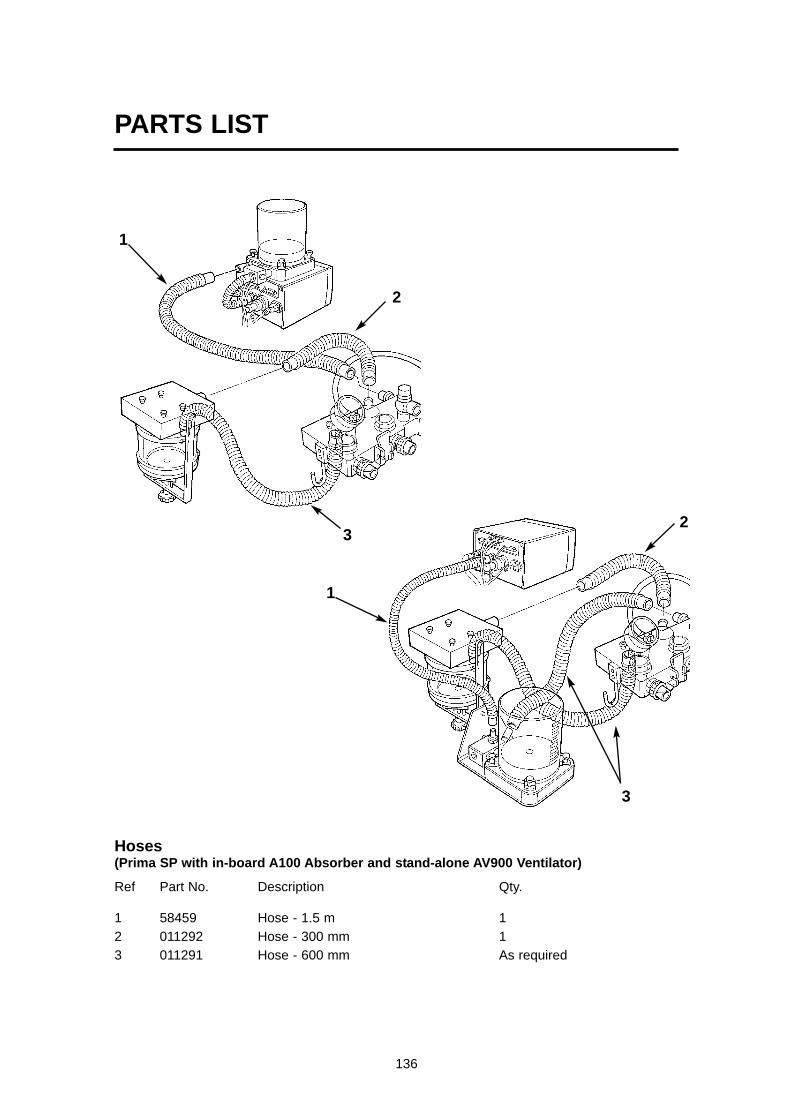
PARTS LIST
136
1
1
3
3
2
2
Hoses(Prima SP with in-board A100 Absorber and stand-alone AV900 Ventilator)
Ref Part No. Description Qty.
1 58459 Hose - 1.5 m 12 011292 Hose - 300 mm 13 011291 Hose - 600 mm As required
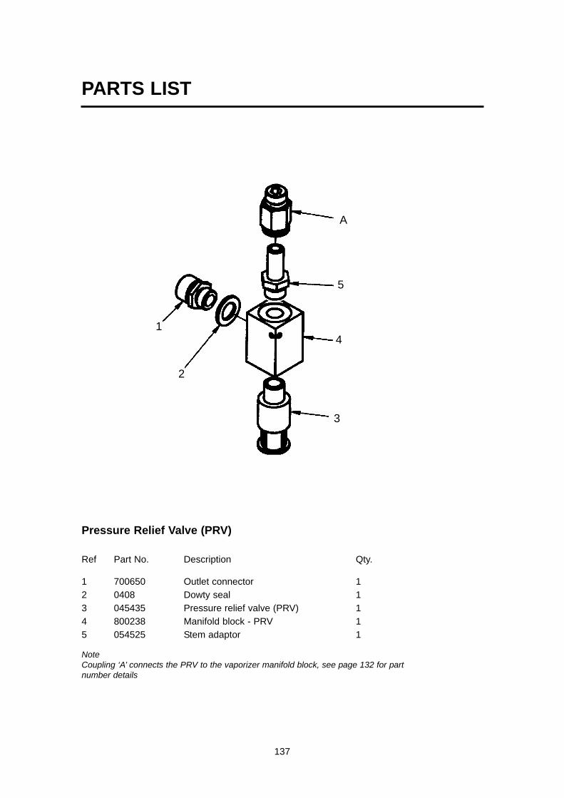
PARTS LIST
137
Pressure Relief Valve (PRV)
Ref Part No. Description Qty.
1 700650 Outlet connector 12 0408 Dowty seal 13 045435 Pressure relief valve (PRV) 14 800238 Manifold block - PRV 15 054525 Stem adaptor 1
NoteCoupling ‘A’ connects the PRV to the vaporizer manifold block, see page 132 for partnumber details
5
4
3
2
1
A

PARTS LIST
138
Miscellaneous Components
Ref Part No. Description Qty.
1 000083 Castor - locked (front) 22 000084 Castor (rear) 2
01252 Star washer, M6 As required800644 Tube hook As required025206 Spring washer, dia 16 mm 4
3 011163 Handle 201028 Screw, M6 x 30 401015 Washer, M6 4800192 T-nut 4
4 800483 Bump stop As required800548 Screw, No 12 x 20 As required
Interface and Spirometry Cables5 300414 1 Interface Cable - AV900 V4 to Prima SP (560 mm)
- 300415 1 Interface Cable Assembly - A100SP Absorber to Prima SP- consists of socket assembly and two cables
4
3
2
1
5

139
Tubing Connectors
2054531Equal tee 5 mm tube
054534Stem adaptor4 mm tube
054528Stem adaptor8 mm tube
054521Straight connector 8 mm tube
054529Stud fitting -male 4 mmtube
054513Equal elbow5 mm tube
054514Swivel elbow6 mm tube
054518Straightadaptor 6 mm tube
054528Stem adaptor8 mm tube
054528Swivel elbow4 mm tube
PARTS LIST

140
11. Appendix
APPENDIX 1
Machines with Oxygen MonitorCare of Back-up Battery
A. Batteries installed in machinesThe batteries must be charged before the machine is releasedfor use with a 24 hour charge. Subsequently the recharge periods for batteries on machinesin store are similar to those in B, below.
Batteries in machines in normal use will be kept charged by theinternal power supply and will only require special charging carefollowing the discharge test carried out during function testing.
B. Battery care/storage requirements.
During storage the batteries will require a periodic recharge, thefrequency of which is determined by the storage temperature,which must not exceed 122oF (50oC).
Storage Rechargetemperature period
38 to 50oC (100 to 122oF) 1 month21 to 38oC (70 to 100oF) 3 months
7 to 21oC (45 to 70oF) 6 months0 to 7oC (32 to 45oF) 9 months-5 to 0oC (23 to 32oF) 12 months
Duration - recharge until the charge current is less than 25 mA(typically overnight).
It is recommended that at each charge an updated label isaffixed to each battery to indicate date of the last charge.
C. Disposal of used batteries
Used batteries must be disposed of according to hospital,local, state and federal regulations.

141
Appendix
APPENDIX 2
Product Classification and Labelling TerminologyThe terms Class 1 and Type B are defined in IEC 601-1 (thestandard for electrical medical equipment).
This symbol denotes: Type B equipment
Type B equipment calls for a particular degree of protection againstelectric shock.
Class 1 equipment has additional protection such that metal parts ofthe unit that are accessible to the user (e.g. the metal casing of theoxygen monitor unit) cannot become live in the event of failure of thebasic insulation of the electrical components within the unit.
This symbol denotes: Refer to the User Manual !

142
APPENDIX 3Lighting System - Wiring Diagram

143
Wiring Diagram

APPENDIX 4Fixings Tightening TorquesNote:Only suitably skilled and trained persons should carry out service andmaintenance procedures on this anaesthesia equipment.
Specific torque values are given where required.
Where specific torque values are not provided, screws and fittings should betightened using a reasonable degree of tightness and skill. Where torqueguidance is required, the following values may be used.
1 General tightening torques.Diameter Type Torque Nm
M3 Cap Head screws 1.7 - 2.0Csk & Button head screws 0.9 - 1.2
M4 Cap Head screws 4.2 - 4.5Csk & Button head screws 3.1 - 3.4
M5 Cap Head screws 7.0 - 7.5Csk & Button head screws 6.0 - 6.5
M6 Cap Head screws 7.5 - 8.0Csk & Button head screws 6.5 - 6.8
M8 Cap Head screws 13 - 13.6Csk & Button head screws 11.5 -12
2 Specific torque values
Diameter Where used Torque NmM4 Cylinder bump stop Tighten to take up slack,
and then 2.5 turnsM6 Cylinder Yokes 7 - 8M6 Yoke mounting plate into rivet bushes 6 - 7M8 Top tray fixings 10 -12M8 Work surface to vertical extrusion 12 -14M16 Castor fixings 20 - 22
CGO Taper fitting 38 - 42M8 Base to vertical extrusions 14 - 16M6 Vertical extrusion T nuts 5 - 6M6 Main control box to vertical extrusions 3 - 4M3 AHD gear grub screws 0.5 - 1.0M4 Front panel 1.0 - 2.0M2.5 Flowmeter cover screws 0.27 - 0.32
Appendix
144

APPENDIX 5
A100SP AbsorberThis information must be used in conjunction with theA100 User Instruction Manual (Cat No 52689).
A100SP Absorber Features
1. Interface with AV900 V4 VentilatorThe A100SP is fitted with fitted with a sensor thatdetects the position of the absorber bag/vent lever.Note that the Bag/Vent lever is fitted on the lefthand side of the manifold block (viewed fromthe front of the machine).The sensor signal cabling is routed internally to aconnector at the rear of the absorber valve block
Operation of the Bag/Vent lever will triggerautomatic Mode switching on the AV900 ventilator,as follows:a) If the Absorber Bag/Vent Lever is moved fromVent to Bag, the ventilator will change from VolumeMode, or Pressure Mode, into Spontaneous Mode.b) Switching the absorber Bag/Vent lever from Bagto Vent will reset the ventilator from SpontaneousMode to Standby Mode.If the ventilator is in any mode other than thosedetailed above, operation of the absorber Bag/Ventlever will not affect the ventilator.NOTE This function can be enabled/disabled through the AV900V4 on-screen menus (Service Sub-menu, see section3.5.4 in the ventilator User Manual).
2. The spirometer flow sensor heads are built into theinspiratory and expiratory airways within theabsorber.The sensor signal cabling is routed internally to aconnector at the rear of the absorber valve block
3. The sensor for the oxygen monitor is built into theinspiratory airway within the absorber.
4. The breathing bag is mounted on a rotating arm.
5. The canister-release mechanism is operated by alever at the base of the canister assembly.
6. Gas flow through the canisters is from top tobottom.
Appendix
145

A100SP Circle System Absorber mounted on Prima SP Anaesthetic Machine The absorber is fitted with optional on/off (bypass) switch, and manometer
1. Adjustable pressure limiting valve (APL valve) 9. Condensate drain
2. Expiratory non-return valve (NRV) 10. Canister lever
3. Manometer (optional) 11. Canister assembly
4. Inspiratory non-return valve (NRV) 12. Reservoir bag
5. Absorber on/off (bypass) switch (optional) 13. Bag swivel arm
6. Inspiratory hose connector 14. Oxygen sensor
7. Bag/ventilator switch
8. Expiratory hose connector
1
23
65
9
7
10
811
12
13
4
14
146

A100SP / AV900 V4 connections
1. Inlet - from DRIVE GAS outlet on AV900control unit.
2. Exhaust outlet from APL Valve - connectto Anaesthetic Gas Scavenge System
3. Inlet - fresh gas hose from anaestheticmachine Common Gas Outlet
4. Outlet - sample line to Pressure MonitorPort on ventilator (AV900 / AV800 etc)
5. Interface cable - Bag/Vent switch (connects internally to Prima SP On/OffSwitch interface, then to connector onAV900 rear panel).
6. Spirometer signal cable - connected tosocket on AV900 V4 rear panel.
7. Oxygen monitor sensor - connected tosocket on AV900 rear panel
1
2 3
4
5 6
Input socket - O2 monitor sensor
Pressure Monitor Port
Prima SP / A100SP AbsorberInterface connector
Drive gas outlet
Spirometer connector
AV900 V4 VentilatorControl Unit Rear Panel
7
DRIVE GAS
147

Breathing System ConnectionsNote1. This Schematic shows an AV900 with
spirometry and oxygen monitor.2. Prima SP interface cabling is shown.3. The absorber is fitted with a Bag/Vent switch.
1. Bellows2. Ventilator Control Unit3. Outlets to Anaesthetic Gas
Scavenging System (AGSS)4. Bacterial Filter5. Absorber valve block6. Heat and moisture exchanger7. Patient8. CGO Block on anaesthetic
machine (Fresh Gas Supply)9. Auxiliary Outlet on anaesthetic
machine (Drive Gas Supply)10. Flow sensor - expiratory
11. Flow sensor - inspiratory12 Connectors - sensor - pressure
monitor13. Expiratory Valve - Absorber14. Inspiratory Valve - Absorber15. Inlet - from Ventilator16. Connector - Reservoir Bag17. Inlet - Absorber - Fresh Gas
Supply18. Drive Gas Inlet - Ventilator19. Drive gas Outlet - ventilator
control unit to bellows20. Outlet - Exhaust Valve
21. Inlet - Bellows Drive Gas22. Outlet - to breathing system23. Input socket - Oxygen monitor
sensor24. Spirometer cable connectors25. Input socket - Prima SP interface
(SP on/off switch, and A100SPAbsorber Bag/Vent lever position)
26. Interface connections on PrimaSP and A100SP
27. APL Valve28 Outlet from APL Valve to AGSS29 Oxygen sensor
1
2
3
67
829
12
101314
15
16
17
18 19 20
24
24
25
12
26
23
27
28
26
21
22
9
11
4
5
Schematic - Breathing System Connections
148

AV900 Ventilator - OxygenSensor Calibration
Calibrate the AV900 oxygen monitorsystem with the sensor in position inthe absorber.
1. Pull the Absorber On / Off lever (1)down to its OFF position. The flow will bypass the absorbent.
2. Remove the breathing circuit hosesfrom the inspiratory and expiratoryconnectors (2) on the absorber.This will give a free flow of oxygenthrough the sensor.
3. Switch on the ventilator and theanaesthetic machine gas deliveryswitch (3).The oxygen monitor automaticallyswitches ON when the ventilator isswitched on.Ensure that all vaporizers are OFF.
4. Apply 100% oxygen only, at 5 L/min,from the flowmeter.
5. Allow the oxygen to flow until theoxygen monitor readout stabilises.
6. Calibrate the sensor, using the AV900ventilator menu procedure.
7. Press the menu switch and select theO2 monitor sub-menu.
8. Scroll to CALIBRATION.If the menu shows 21% (calibrationusing air), press the navigator wheelto switch to 100% (calibration usingoxygen).
9. A message will flash on the screen:O2 AT 100% ?
Press the button to confirmNOTEThe message:
OXYGEN SENSOR LOW OUTPUTwill appear on screen if the user attemptsto calibrate at 21% in 100% oxygen.
10. Repeat operations 8 and 9 twicemore.
11. Scroll to ESCAPE FROM MENUSand press the wheel to exit.
12. Turn off the flow of oxygen.
12
O2 MONITOR : ON> CALIBRATION: 100%
HIGH ALARM SETLOW ALARM SETESCAPE FROM MENUS
O2 Monitor sub-menu - calibration
AV900OFFON~ On/Off Switch
Alarm Mute
Menu Switch
Navigator Wheeland Press Button
3
149

AV900 Ventilator - SpirometryCalibration
The Spirometry heads must be calibratedwith zero flow going through them.
1. Turn the Prima SP off at the Gas Deliveryswitch (1).This will stop all gas flows (including theAHD basal flow).This will also turn the AV900 off.
2. Turn the AV900 on at the ventilator (Do notuse the SP Gas Delivery switch).
3. Remove the breathing circuit hoses fromthe inspiratory and expiratory connectors(2) on the absorber.
4. Disconnect the fresh gas hose from theCGO block on the anaesthetic machine.
5. Disconnect the hose from the APL valveoutlet (3) at the rear of the manifold block
6. a) Ensure that the ventilator bellows isempty, or, b) Remove the bag, and set the Bag/Ventlever (4) to Bag position.
7. Calibrate the spirometer via the ventilatormenu procedure.NOTEDo NOT remove the spirometer heads.
8. Press the menu switch on the front panel.
9. Scroll down the main menu and selectSPIROMETRY.
10. Scroll down the sub-menu and selectCALIBRATION.
11. Turn the wheel to switch display toCALIBRATION: cal
12. A message will appear:Remove the spirometer head
Do NOT remove the spirometer heads
13. Press the wheel to initiate calibration.
14. Repeat operations 8 to 12, twice more.
15. Calibration is completed.
16. Scroll to ESCAPE FROM MENUS.
17. Press the wheel to confirm.
21
O2 MONITOR> SPIROMETRY
FRESH GAS COMPENSATION : ONGAS MIXTUREVOLUME TYPEWAVEFORM SERVICEESCAPE FROM MENUS
SPIROMETRY : ON> CALIBRATION : cal
ESCAPE FROM MENUS
Spirometry sub-menu
Main menu
AV900OFFON~ On/Off Switch
Alarm Mute
Menu Switch
Navigator Wheeland Press Button
4
3
150

Filling and Changing CO2Absorbent
WARNINGIf the absorbent is to be changed duringclinical use, the bypass switch (1) must be inthe ‘Absorber OFF’ position, and adequatefresh gas flow must be maintained to preventexcessive build up of CO2.
Removing the canisters1. Turn the lever (2) at the base of the
absorber anti-clockwise. This leaves space between the topand bottom of the canister frame forthe top canister (3) to be removedsideways after disengaging the rubberseals by vertical movement.
2. The absorbent in the top canister isalways exhausted first, so thecanisters should be rotated as follows:
(a) lift the top canister from the frame andreplace the absorbent. Place to oneside, for refitment in the lowerposition,
(b) the lower canister should be refitted inthe upper position - see below.
Refitting the canisters
CAUTIONEfficient use of soda lime is only achieved if thenewly refilled canister is replaced in the lowerposition.
1. Refit the canisters into the frame, withthe newly filled canister in the lowerposition.Check that the seals and canistersalign
2. Ensure that the top canister (3)engages correctly into the top seal (4)as you rotate the lever (2) clockwise tothe vertical, locked-on position .
3. Leak test the absorber – see section6.2 in the A100 User Manual.
1
2
4
3
151

SterilisationCaution Do not autoclave:
Oxygen Sensor ManometerTop cover Bottom cover
Absorber Assembly - removal beforeSterilisation
WARNING The absorber assembly weighs approximately 17 kg. Take care when the absorber is removed from the machine.
Remove1. Disconnect the cable (1) from the O2 sensor (2).
Unscrew the sensor from the manifold block.Do not autoclave.
2. At the rear of the absorber manifold block,disconnect the hoses (apart from the fresh gas hose- 3) and cables.Disconnect the fresh gas hose from the CGO blockon the anaesthetic machine.
3. Drain the condensate from the absorber.Refer to section 7.3.1 in the A100 User Manual.WARNING Condensation, which may collect inthe bottom of the absorber is caustic and caremust be taken not to spill it on the skin whendraining the condensate trap. After draining ensure that the drain valve (4) isfully closed.
4. Apply the brake on the anaesthetic machine.Lift the right-hand side of the absorber and slowlyslide the assembly out from the side of the machine.The absorber assembly weighs approximately17 kg - support the absorber at the front andside as it is removed from the machine.
Remove the covers and canisters5. Press the retaining clip and detach the manometer
(5). Do not autoclave6. Unscrew the retaining nut (6) and remove the bag
arm (7).7. Remove the screws (8) securing the top cover (9),
and detach the cover from the absorber.Do not autoclave.
8. Turn the lever (10) at the base of the absorber anti-clockwise, and remove the top canister (11)sideways after disengaging the rubber seals byvertical movement.Remove the bottom canister.Dispose of the soda lime granules, and wash thecanisters.Do not refit the canisters until the autoclaveprocedure is completed.
9. Remove the screws (12) securing the bottom cover(13), and detach the cover from the absorber.Do not autoclave.
12
3
4
10
9
5
12
13
67
8
11
152

Sterilisation and Autoclave
CAUTIONTo prevent possible damage to components, peak sterilisation temperatures mustnot exceed :54oC (130oF) for gas (ethylene oxide) or,
134oC (275oF) for steam autoclave.
Low temperature autoclave must not exceed 120oC
Following sterilisation with ethylene oxide, components must be quarantined in awell ventilated area to allow dissipation of any residual gases.Follow the recommendations given by the steriliser manufacturer for aerationperiods required.
Sterilisation and Autoclave Treatment Table
ITEM METHOD
A100SP Absorber assembly Gas, liquid, autoclave
Absorber canisters Liquid, low temperature autoclave
Ventilator bellows assembly components:
Bellows Gas, liquid, autoclave (20 cycles max.)
Hoses Gas, liquid, autoclave
Bellows base Gas, liquid, autoclave.
Bellows canister Liquid, autoclave
Exhalation valve assembly Gas, liquid, pasteurise, low temperature autoclave
NOTEExamples of suitable liquid agents are: Nu-Cidex, Sporicidin, and Sonacide.
Bellows Assembly10. Turn the bellows housing (12) anti-clockwise,
then lift it from the base.Remove the bellows (13).
11 Undo the three retaining screws, thenremove the exhalation valve assembly (14).
Cleaning procedures before sterilisation
Absorber :Clean the frame and inspiratory and expiratoryvalve assemblies - refer to section 8.4 in the A100User Manual.The absorber assembly can then be autoclaved asa single unit.
Ventilator Bellows Assembly:Refer to section 7.2 in the AV900 V4 user manual
12
13
14
153

After Cleaning / Sterilisation1. Check that all hoses and cables are
secure and correctly routed.
2. Refit the covers.
3. Refit the canisters - see page 7 of thisdatasheet - Filling and Changing CO2Absorbent.
4. Refit the bag arm and bag.
5. Refit the Manometer.
Refitting the Absorber to themachine
WARNING The absorber assembly weighsapproximately 17 kg. Take care when lifting the absorber andduring installation.
1. Apply the brake on the anaestheticmachine.
2. Align the mounting buttons (1) on thetop of the absorber manifold blockwith the slots in the mounting plate (2)on the anaesthetic machine.
3. Slide the absorber into position.Continue to push the unit inwardsuntil the right-hand side mountingbuttons (1) drop into recesses in themounting plate. This indicates thatthe assembly is correctly installed.Check that the assembly cannot bemoved to the left.
4. Reconnect the hoses and cables atthe rear of the absorber manifoldblock (3).Check for correct fitment with theillustration on page 3 of thisdatasheet.
5. Refit the oxygen sensor (4) andreconnect the cable (5).
Ventilator Bellows Assembly6. Reassemble the bellows
components.Refer to sections 7.2 and 5.2 in theAV900 User Manual.Important - check that the O-rings(6 and 7) are in position.
54
1
2
3
6
7154

Pre-use Checks
Carry out the Pre-use Checks listed in Section 6 of the A100User Manual.
NOTEA) The A100SP is not fitted with a PEEP valve.
B) Check the operation of the Bag/Vent switch detector - seesection 3.5.14 in the AV900 V4 ventilator user manual.
Ordering Information
Retrofit Kits
To retrofit an A100SP absorber to an existing Prima SP (notapplicable to Prima), order one of the following kits:
58113 A100SP (UK specification) retrofit kit - Prima SP102
58114 A100SP (US specification) retrofit kit - Prima SP102
58115 A100SP (UK specification) retrofit kit - Prima SP101
58116 A100SP (US specification) retrofit kit - Prima SP101
Each kit consists of an A100SP absorber, complete with AV-seriesbellows assembly, and mounts.
Accessories
Fresh gas hose 52590Manometer 58112Breathing circuit (black rubber) 58436Absorber detachables 52582
Note:1. Absorber detachables consists of:
3 litre breathing bag1.05 m (42 inch) breathing tubeFemale mountConnector mountFacemask elbowY piece
2. All standard connectors are for use with 30 mm taper anti-pollutionsystems. Models compatible with 19 mm systems are available on request.
155


Cat. No. 52793Doc. No. PR SP 0204SMMarch 2004
Copyright © Penlon Ltd 2004 All rights reserved.
Penlon Limited, Abingdon Science Park, Barton Lane, Abingdon, OX14 3PH, UK.
Service Tel: 44 (0) 1235 547076 UK Sales Tel: 01235 547036 International Sales Tel: 44 (0) 1235 547001 Service Fax: 44 (0) 1235 547062 UK Sales Fax: 01235 547023 International Sales Fax: 44 (0) 1235 547021E-mail: [email protected] [email protected] [email protected]