prima - godiva...prima workshop manual p1 single pressure model p2 twin pressure model prima p1...
TRANSCRIPT
Prima Workshop Manual
P1 Single Pressure Model P2 Twin Pressure Model
Prima P1
Prima P2
GODIVA LIMITED A Unit of IDEX Corporation Charles St Warwick CV34 5LR England +44 (0)1926 623600 +44 (0)1926 623666 www.godiva.co.uk [email protected]
GP/290 Issue 7, July 2019
1
©Godiva Ltd. Our policy is one of continuous development. We therefore reserve the right to amend specifications without notice or obligation.
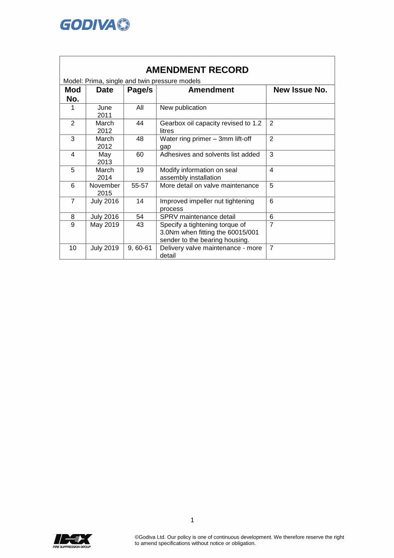
AMENDMENT RECORD Model: Prima, single and twin pressure models
Mod No.
Date Page/s Amendment New Issue No.
1 June 2011
All New publication
2 March 2012
44 Gearbox oil capacity revised to 1.2 litres
2
3 March 2012
48 Water ring primer – 3mm lift-off gap
2
4 May 2013
60 Adhesives and solvents list added 3
5 March 2014
19 Modify information on seal assembly installation
4
6
November 2015
55-57 More detail on valve maintenance 5
7 July 2016 14 Improved impeller nut tightening process
6
8 July 2016 54 SPRV maintenance detail 6
9 May 2019 43 Specify a tightening torque of 3.0Nm when fitting the 60015/001 sender to the bearing housing.
7
10 July 2019 9, 60-61 Delivery valve maintenance - more detail
7

2
©Godiva Ltd. Our policy is one of continuous development. We therefore reserve the right to amend specifications without notice or obligation.
CONTENTS
AMENDMENT RECORD ................................................................................. 1
CONTENTS ..................................................................................................... 2
SAFETY ........................................................................................................... 5
IN OPERATION ......................................................................................................... 5 TRAINING ................................................................................................................ 5 MAINTENANCE ........................................................................................................ 5 ENVIRONMENTAL PROTECTION ................................................................................ 5 RISK ASSESSMENT .................................................................................................. 5 TRANSPORTATION AND STORAGE ............................................................................. 5 WARRANTY ............................................................................................................. 6 ASSOCIATED PUBLICATIONS .................................................................................... 6
PUMP SPECIFICATION NUMBERING ........................................................... 6
......................................................................................................................... 6
ENVIRONMENTAL PROTECTION ................................................................. 7
OPERATOR MAINTENANCE LOG ................................................................ 8
MAINTENANCE SCHEDULE .......................................................................... 9
REMOVAL & INSTALLATION ...................................................................... 10
INTRODUCTION ...................................................................................................... 10 PRECAUTIONS ....................................................................................................... 10 POST REPAIR AND ASSEMBLY ................................................................................ 10 1. SUCTION TUBE AND FRONT WEARING RING .......................................................... 11
Removal .......................................................................................................................... 11 Installation ....................................................................................................................... 11
2. LOW PRESSURE IMPELLER ................................................................................. 13 Removal .......................................................................................................................... 13 Installation ....................................................................................................................... 14
3. REAR WEAR RING ............................................................................................. 14 Removal .......................................................................................................................... 14 Installation ....................................................................................................................... 15 Removal .......................................................................................................................... 15 Installation ....................................................................................................................... 16
4. P2 ONLY - HIGH PRESSURE IMPELLER ................................................................ 17 Removal .......................................................................................................................... 17
5. P2 ONLY - HIGH PRESSURE IMPELLER - MAINTENANCE ........................................ 17 Installation ....................................................................................................................... 17
6. MECHANICAL SEAL MAINTENANCE ...................................................................... 20 Removal .......................................................................................................................... 20 Installation ....................................................................................................................... 20
7. VOLUTE BODY ................................................................................................... 22 Removal .......................................................................................................................... 22 Installation ....................................................................................................................... 22
8. LOW PRESSURE MANIFOLD AND HIGH/LOW PRESSURE FILTER HOUSING (P2) ...... 22 Removal – High/Low pressure Filter Housing ................................................................ 22 Removal – Low pressure manifold ................................................................................. 23 Removal .......................................................................................................................... 23
9. PRIMING VALVE ................................................................................................. 24 Removal .......................................................................................................................... 24
10. PRIMER SYSTEM – RECIPROCATING PISTON PRIMER ......................................... 25 Removal / Maintenance .................................................................................................. 25
3
©Godiva Ltd. Our policy is one of continuous development. We therefore reserve the right to amend specifications without notice or obligation.
11. PUMP HEAD .................................................................................................... 32 Removal .......................................................................................................................... 32 Installation ....................................................................................................................... 32
12. FRONT END OIL SEAL ...................................................................................... 33 Removal .......................................................................................................................... 33 Installation ....................................................................................................................... 33
12. REAR OIL SEAL ............................................................................................... 33 Removal .......................................................................................................................... 33 Installation ....................................................................................................................... 33
13. BEARING HOUSING .......................................................................................... 33 Removal .......................................................................................................................... 33 Rebuild / Installation ........................................................................................................ 35
14. GEARBOX (OPTIONAL) ..................................................................................... 45 15. WATER RING PRIMER (OPTIONAL) .................................................................... 47
To Remove ..................................................................................................................... 47 Maintenance ................................................................................................................... 47 To Refit............................................................................................................................ 49
16. PUMP TESTS ................................................................................................... 50 Vacuum Test ................................................................................................................... 50 Pressure Test .................................................................................................................. 50 Water Ring Primer (optional priming system) ................................................................. 50 Pressure Relief Valve (PRV) and Thermal Relief Valve (TRV) Test .............................. 51 Thermal Relief Valve Maintenance ................................................................................. 51 Suction Pressure Relief Valve Maintenance ................................................................... 54
17. DELIVERY VALVES ........................................................................................... 57 Ball Valve Type ............................................................................................................... 57 Screw-down Type ........................................................................................................... 59 Continental Delivery Valves ............................................................................................ 64 Instantaneous Connector Servicing Procedure: ............................................................. 66
17. TIGHTENING TORQUES ..................................................................................... 67 18. SPECIAL TOOLS ............................................................................................... 67 19. ADHESIVES, SOLVENTS AND GREASES LIST ...................................................... 68

4
©Godiva Ltd. Our policy is one of continuous development. We therefore reserve the right to amend specifications without notice or obligation.
Page intentionally left blank.

5
©Godiva Ltd. Our policy is one of continuous development. We therefore reserve the right to amend specifications without notice or obligation.
SAFETY
Please read this manual before operating the machinery. Safety notices -
= non-compliance could affect safety = in case of damage to pump
In operation
▪ Rotating parts must be guarded against accidental contact.
▪ Do not insert items into the suction tube when pump is running.
▪ Discharge hoses must not be disconnected when the unit is running.
▪ No components must be unfastened when the unit is running.
▪ When installing or removing the pump, suitable lifting equipment must be used.
▪ Suitable ear protection must be worn when pump is running – if necessary.
Training
Godiva pumps must only be operated by trained personnel.
Maintenance
The user must maintain the equipment in an operational condition, as per regulation 5 in the Provision and Use of Work Equipment Regulations 1998.
Environmental Protection
Used oil from the pump must be disposed of in accordance with your local regulations
Risk Assessment
It is the duty of the pump installer to make a risk assessment of their operations when installing the pump, please contact Godiva Ltd. if assistance is required.
Transportation and Storage
The pump is supplied mounted on a wooden pallet and covered with a tri-walled cardboard box. This protection is suitable for standard methods of freight handling using forklift trucks. No more than one pump should be stacked on top of another. The tri-walled cardboard box is not suitable for storage when open to the elements. The pump is sprayed internally with a moisture inhibitor when leaving the factory, this treatment may be required if the pump is in long term storage (6 months or more) before use. On receipt of the pump a full inspection must be carried out, if any damage has occurred please contact Godiva Ltd.
IMPORTANT
!

6
©Godiva Ltd. Our policy is one of continuous development. We therefore reserve the right to amend specifications without notice or obligation.
Warranty
For all issues relating to warranty claims please contact Godiva Ltd.. Please be prepared to quote the six figure pump serial number located on the pump volute. Gauges (if fitted) Do not clean the glass surfaces of the gauges with abrasive or solvent cleaners. These will cloud the glass surface. Use a mild detergent and water.
Associated Publications
Publication Part No Installation and Operation Manual GP/287 P1 Spare Parts Manual GP/281 P2 Spare Parts Manual GP/258
PUMP SPECIFICATION NUMBERING
P C 1 A 20 10 601123 = typical six figure serial number
Stamped on volute body (boss at top left)
Nominal pressure in bars Nominal flow in litres / minute x 100 A = Aluminium B = Bronze 1 = Single pressure, 2 = Twin pressure C = Compressed air foam system fitted (option) P = Prima series
7
©Godiva Ltd. Our policy is one of continuous development. We therefore reserve the right to amend specifications without notice or obligation.
ENVIRONMENTAL PROTECTION
It is prohibited to pour oil and other contaminants onto the ground, down sewers, drains, or into water courses. Dispose of lubricants through authorised waste disposal contractors, licensed waste disposal sites, or to the waste reclamation trade. If in doubt, contact your Local Environmental Agency for advice regarding disposal policies.
8
©Godiva Ltd. Our policy is one of continuous development. We therefore reserve the right to amend specifications without notice or obligation.
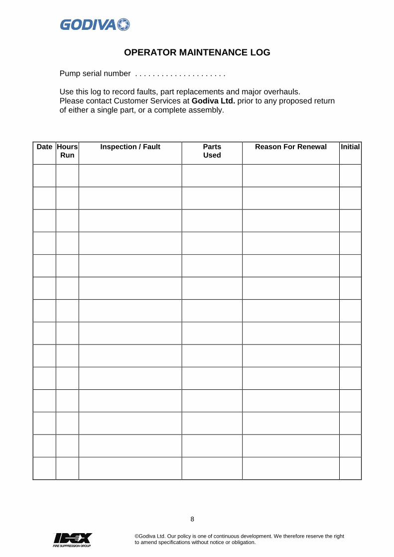
OPERATOR MAINTENANCE LOG
Pump serial number . . . . . . . . . . . . . . . . . . . . . Use this log to record faults, part replacements and major overhauls. Please contact Customer Services at Godiva Ltd. prior to any proposed return of either a single part, or a complete assembly.
Date Hours Run
Inspection / Fault Parts Used
Reason For Renewal Initial
9
©Godiva Ltd. Our policy is one of continuous development. We therefore reserve the right to amend specifications without notice or obligation.
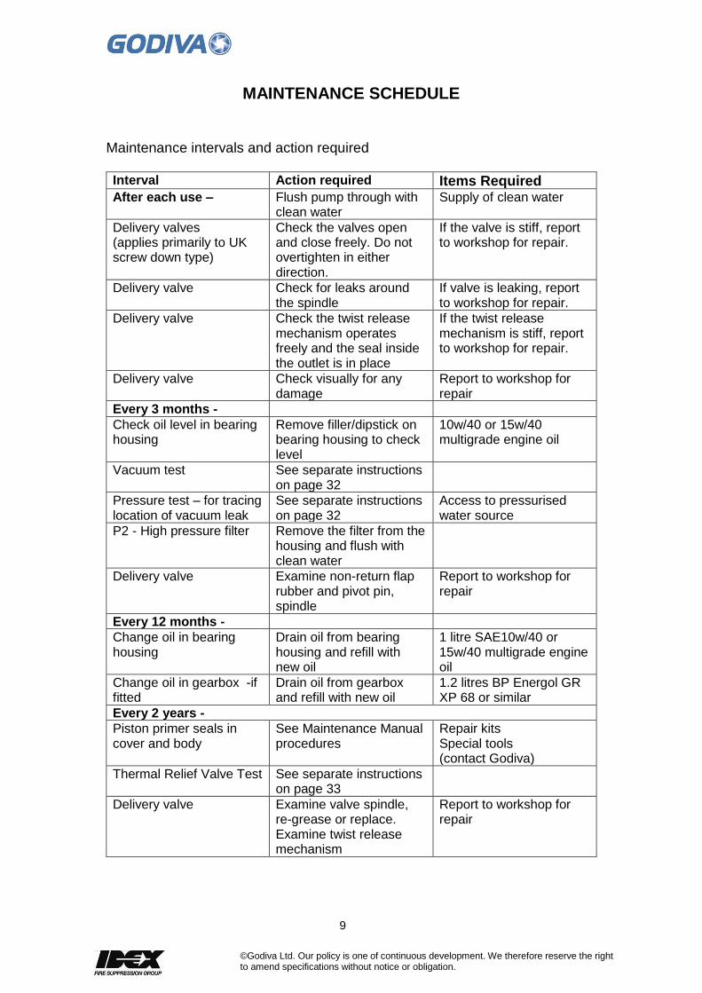
MAINTENANCE SCHEDULE
Maintenance intervals and action required Interval Action required Items Required After each use –
Flush pump through with clean water
Supply of clean water
Delivery valves (applies primarily to UK screw down type)
Check the valves open and close freely. Do not overtighten in either direction.
If the valve is stiff, report to workshop for repair.
Delivery valve Check for leaks around the spindle
If valve is leaking, report to workshop for repair.
Delivery valve Check the twist release mechanism operates freely and the seal inside the outlet is in place
If the twist release mechanism is stiff, report to workshop for repair.
Delivery valve Check visually for any damage
Report to workshop for repair
Every 3 months -
Check oil level in bearing housing
Remove filler/dipstick on bearing housing to check level
10w/40 or 15w/40 multigrade engine oil
Vacuum test
See separate instructions on page 32
Pressure test – for tracing location of vacuum leak
See separate instructions on page 32
Access to pressurised water source
P2 - High pressure filter Remove the filter from the housing and flush with clean water
Delivery valve Examine non-return flap rubber and pivot pin, spindle
Report to workshop for repair
Every 12 months -
Change oil in bearing housing
Drain oil from bearing housing and refill with new oil
1 litre SAE10w/40 or 15w/40 multigrade engine oil
Change oil in gearbox -if fitted
Drain oil from gearbox and refill with new oil
1.2 litres BP Energol GR XP 68 or similar
Every 2 years -
Piston primer seals in cover and body
See Maintenance Manual procedures
Repair kits Special tools (contact Godiva)
Thermal Relief Valve Test See separate instructions on page 33
Delivery valve
Examine valve spindle, re-grease or replace. Examine twist release mechanism
Report to workshop for repair

10
©Godiva Ltd. Our policy is one of continuous development. We therefore reserve the right to amend specifications without notice or obligation.
REMOVAL & INSTALLATION
Introduction
Instructions particular to the repair of Godiva Prima Fire Pump series are detailed in the following sections. These instructions describe the complete strip-down of the pump. To reduce unnecessary work and avoid the introduction of other issues, only dismantle those parts necessary to effect inspection and or repair. P1 and P2 Models – for both pumps the majority of parts are common. Where parts are unique to the P1 or P2 pump, this is indicated in the text.
Precautions
Before carrying out repair work, take the following precautions:
o Drain the volute of water.
Post Repair and Assembly
On completion of work:
o Carry out vacuum test. o Complete the maintenance log.

11
©Godiva Ltd. Our policy is one of continuous development. We therefore reserve the right to amend specifications without notice or obligation.
1. Suction tube and front wearing ring
Removal
1.1 Undo the 12 x hexagon head bolts (shown). If necessary remove the tank to pump line, collecting head and RTP unit. Disconnect the vacuum gauge tubing from the top of the suction tube.
To remove and replace the front wearing ring in the locating bore in the suction cover plate, undo the 4 x cap screws and washers
Check the large internal diameter of the wearing ring in several places. If dimension A exceeds the limit given in the table the wearing ring must be replaced.
Pump Internal Ø Limit - mm
P1_2010 / P2_3010 140.16 / 140.10
P1_4010 170.685 / 170.632
P1_6010 187.07 / 187.00
Pump Internal Ø Limit - mm
P2_2010 / P2_3010 140.16 / 140.10
P2_4010 170.685 / 170.632
P2_6010 187.07 / 187.00
Ø
Installation
Installation is the reverse of removal noting: When replacing the front wear ring apply Loctite 243 to screw threads and torque to 12 Nm.
12
©Godiva Ltd. Our policy is one of continuous development. We therefore reserve the right to amend specifications without notice or obligation.
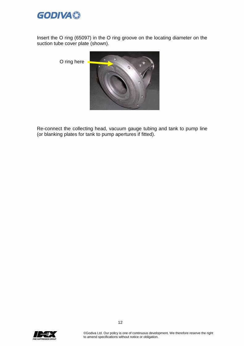
Insert the O ring (65097) in the O ring groove on the locating diameter on the suction tube cover plate (shown).
Re-connect the collecting head, vacuum gauge tubing and tank to pump line (or blanking plates for tank to pump apertures if fitted).
O ring here

13
©Godiva Ltd. Our policy is one of continuous development. We therefore reserve the right to amend specifications without notice or obligation.
2. Low Pressure Impeller
Removal
To remove and inspect the low pressure impeller, remove the suction tube and associated parts as described in section 1. This gives direct access to the low pressure impeller leaving the volute body in-situ. To remove the impeller it may be necessary to fit a shaft locking screw in the aperture provided at the rear of the bearing housing. Remove the impeller nut and the pair of lock washers, withdraw the impeller from the keyed pump shaft.
Check the wearing diameter on the impeller in several places. If the diameter is less than stated in the table below, a new impeller should be fitted. P1 Model
Pump Front Diameter A mm Rear Diameter B mm
P1_2010 / 3010 139.3 mm 146.1
P1_4010 169.5 mm 170.8
P1_6010 188.6mm 184.2
14
©Godiva Ltd. Our policy is one of continuous development. We therefore reserve the right to amend specifications without notice or obligation.
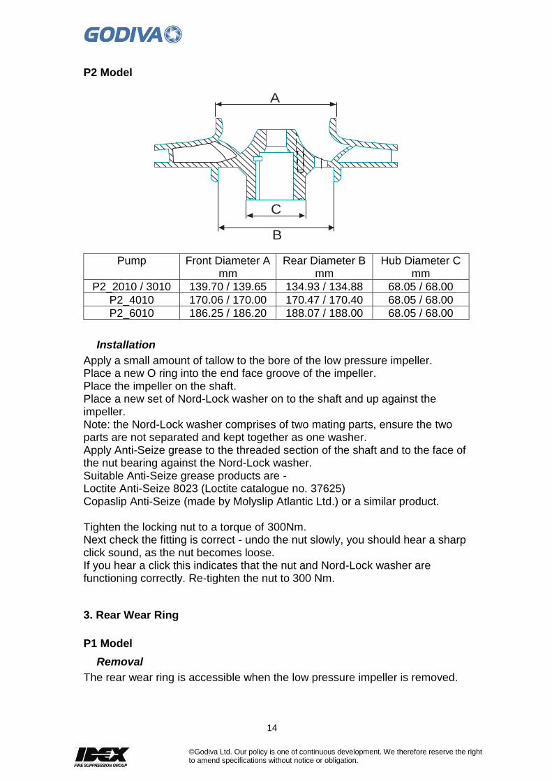
P2 Model
A
C
B
Pump Front Diameter A mm
Rear Diameter B mm
Hub Diameter C mm
P2_2010 / 3010 139.70 / 139.65 134.93 / 134.88 68.05 / 68.00
P2_4010 170.06 / 170.00 170.47 / 170.40 68.05 / 68.00
P2_6010 186.25 / 186.20 188.07 / 188.00 68.05 / 68.00
Installation
Apply a small amount of tallow to the bore of the low pressure impeller. Place a new O ring into the end face groove of the impeller. Place the impeller on the shaft. Place a new set of Nord-Lock washer on to the shaft and up against the impeller. Note: the Nord-Lock washer comprises of two mating parts, ensure the two parts are not separated and kept together as one washer. Apply Anti-Seize grease to the threaded section of the shaft and to the face of the nut bearing against the Nord-Lock washer. Suitable Anti-Seize grease products are - Loctite Anti-Seize 8023 (Loctite catalogue no. 37625) Copaslip Anti-Seize (made by Molyslip Atlantic Ltd.) or a similar product. Tighten the locking nut to a torque of 300Nm. Next check the fitting is correct - undo the nut slowly, you should hear a sharp click sound, as the nut becomes loose. If you hear a click this indicates that the nut and Nord-Lock washer are functioning correctly. Re-tighten the nut to 300 Nm.
3. Rear Wear Ring
P1 Model
Removal
The rear wear ring is accessible when the low pressure impeller is removed.

15
©Godiva Ltd. Our policy is one of continuous development. We therefore reserve the right to amend specifications without notice or obligation.
To remove the wear ring undo the four screws and washers retaining the ring against the pump head. The wear ring can be eased away from the pump head by means of two screws inserted into the adjacent tappings. Check the wearing diameters as follows –
Pump Ø X
P1_2010/3010 144.9mm
P1_4010 169.5mm
P1_6010 183mm
Installation
When relocating the rear wear ring into the pump head, ensure the priming port in the ring is located at the top. When replacing the rear wear ring apply Loctite 243 to screw threads and torque to 12 Nm. P2 Model
Removal
The rear wear ring is accessible when the low pressure impeller is removed. To remove the wear ring undo the four screws and washers retaining the ring against the high pressure cover plate. The wear ring can be eased away from the cover plate by means of two screws inserted into the adjacent tappings. Check the wearing diameters as follows –
X
Y
Pump Ø X Ø Y
P2_2010/3010 134.440 / 134.400 68.500 / 68.450
P2_4010 170.000 / 169.937 68.500 / 68.450
P2_6010 187.45 / 187.40 68.500 / 68.450
P1_2010/3010 P1_4010/6010
16
©Godiva Ltd. Our policy is one of continuous development. We therefore reserve the right to amend specifications without notice or obligation.
Installation
When relocating the rear wear ring into the cover plate, ensure the priming port in the ring is located at the top. When replacing the rear wear ring apply Loctite 243 to screw threads and torque to 12 Nm.
17
©Godiva Ltd. Our policy is one of continuous development. We therefore reserve the right to amend specifications without notice or obligation.
4. P2 Only - High Pressure Impeller
Removal
To access the high pressure impeller the suction tube and low pressure impeller must be removed as per sections 1 and 2. Remove the high pressure cover plate by undoing the 12 off cap screws. Insert 3 off M8 bolts into the extractor holes around the edge of the plate. Screw the bolts in evenly until the plate moves forward. Remove the cover plate and high pressure impeller. Clean the cover plate and pump body jointing faces.
5. P2 Only - High Pressure Impeller - Maintenance
Check the high pressure impeller, pump body, mechanical seal assembly for wear. Replace any worn parts.
Installation
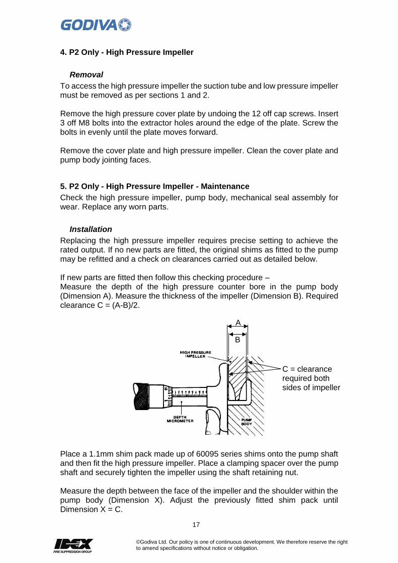
Replacing the high pressure impeller requires precise setting to achieve the rated output. If no new parts are fitted, the original shims as fitted to the pump may be refitted and a check on clearances carried out as detailed below. If new parts are fitted then follow this checking procedure – Measure the depth of the high pressure counter bore in the pump body (Dimension A). Measure the thickness of the impeller (Dimension B). Required clearance C = (A-B)/2.
Place a 1.1mm shim pack made up of 60095 series shims onto the pump shaft and then fit the high pressure impeller. Place a clamping spacer over the pump shaft and securely tighten the impeller using the shaft retaining nut. Measure the depth between the face of the impeller and the shoulder within the pump body (Dimension X). Adjust the previously fitted shim pack until Dimension X = C.
A
B
C = clearance required both sides of impeller

18
©Godiva Ltd. Our policy is one of continuous development. We therefore reserve the right to amend specifications without notice or obligation.
Remove the impeller to re-fit the mechanical seal and main key on the pump shaft – if they have been removed. Replace the high pressure impeller on the pump shaft. Available shims for setting the high pressure impeller -
0.0508mm /0.002”
0.127mm /0.005”
0.254mm /0.010”
0.3810mm /0.015”
Pack Thickness mm
Pack Thickness inches
Part No. 60095/01
Part No. 60095/02
Part No. 60095/03
Part No. 60095/04
0.0508 0.002 Qty 1
0.1016 0.004 Qty 2
0.127 0.005 Qty 1
0.1524 0.006 Qty 3
0.1778 0.007 Qty 1 Qty 1
0.2032 0.008 Qty 4
0.2286 0.009 Qty 2 Qty 1
0.254 0.010 Qty 1
0.2794 0.011 Qty 3 Qty 1
0.3048 0.012 Qty 1
0.3302 0.013 Qty 4 Qty 1
0.355 0.014 Qty 2 Qty 1
0.3810 0.015 Qty 1
0.4064 0.016 Qty 3 Qty 1
0.4318 0.017 Qty 1 Qty 1 Qty 1
0.4572 0.018 Qty 4 Qty 1
0.4826 0.019 Qty 2 Qty 1
0.508 0.020 Qty 2
0.5334 0.021 Qty 3 Qty 1
0.5588 0.022 Qty 1 Qty 2
0.5842 0.023 Qty 4 Qty 1
0.6096 0.024 Qty 2 Qty 2
0.635 0.025 Qty 1 Qty 1
0.6604 0.026 Qty 3 Qty 2
0.6858 0.027 Qty 1 Qty 1 Qty 2
0.7112 0.028 Qty 4 Qty 2
0.7366 0.029 Qty 2 Qty 1 Qty 1
0.7620 0.030 Qty 2
Clamping spacer

19
©Godiva Ltd. Our policy is one of continuous development. We therefore reserve the right to amend specifications without notice or obligation.
Before replacing the high pressure cover plate, ensure the auto drain ball bearing is moving freely in the high pressure drain valve. If the retaining plate does have to be removed ensure the two cap screws are secured with Loctite 243 to the threads.
Replace the high pressure cover plate against the pump body. Retain with 12 off cap screws and torque to 44 Nm. Apply Molykote P37 or similar under the head of the cap screws to prevent galling.
Place the O ring (57044) into the groove on the end of the pump shaft, and two O rings into the grooves in the transfer tube openings in the pump body ready to receive the low pressure manifold and high/low pressure filter housing.
20
©Godiva Ltd. Our policy is one of continuous development. We therefore reserve the right to amend specifications without notice or obligation.
6. Mechanical Seal Maintenance
With the high pressure impeller (P2) or low pressure impeller (P1) removed the carbon seal can be examined for wear. If there has been excessive leakage past the carbon seal and through the drain hole in the pump head, examine the carbon seal. If the face of the carbon seal is scored, this will have to be replaced along with the mating part, the silicon carbide ring located in the rear side of the HP impeller (P2) or low pressure impeller (P1).
Removal
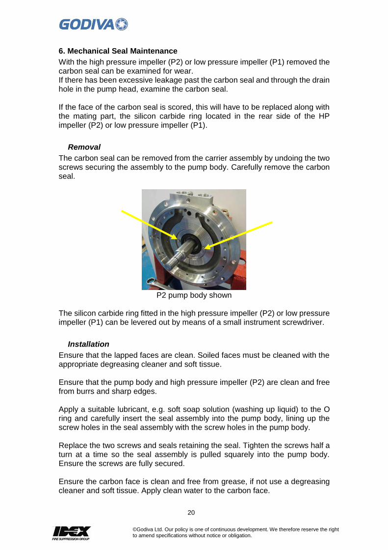
The carbon seal can be removed from the carrier assembly by undoing the two screws securing the assembly to the pump body. Carefully remove the carbon seal.
P2 pump body shown
The silicon carbide ring fitted in the high pressure impeller (P2) or low pressure impeller (P1) can be levered out by means of a small instrument screwdriver.
Installation
Ensure that the lapped faces are clean. Soiled faces must be cleaned with the appropriate degreasing cleaner and soft tissue. Ensure that the pump body and high pressure impeller (P2) are clean and free from burrs and sharp edges. Apply a suitable lubricant, e.g. soft soap solution (washing up liquid) to the O ring and carefully insert the seal assembly into the pump body, lining up the screw holes in the seal assembly with the screw holes in the pump body. Replace the two screws and seals retaining the seal. Tighten the screws half a turn at a time so the seal assembly is pulled squarely into the pump body. Ensure the screws are fully secured. Ensure the carbon face is clean and free from grease, if not use a degreasing cleaner and soft tissue. Apply clean water to the carbon face.
21
©Godiva Ltd. Our policy is one of continuous development. We therefore reserve the right to amend specifications without notice or obligation.
Fit the opposite seal mating ring assembly into the high pressure impeller bore using fitting tool 60275/08. Ensure the face of the mating ring is fitted squarely in the impeller housing within 0.1mm. Use a soft soap solution on seal cup to ease fitting. Carefully fit the high pressure impeller onto the shaft and continue with pump build.

22
©Godiva Ltd. Our policy is one of continuous development. We therefore reserve the right to amend specifications without notice or obligation.
7. Volute Body
It is unlikely that the volute body will need to be removed during normal service. But if removal is required -
Removal
Remove the suction tube as in section 1. The volute is mounted to the pump body by 12 off capscrews. The volute may be mounted on either standard rotation or reverse rotation pumps, and must be fitted the correct way for the rotation of the pump. The arrow cast on the volute will point in the direction of rotation.
Installation
Installation is a reversal of the removal process.
8. Low Pressure Manifold and High/Low Pressure Filter Housing (P2)
The low pressure manifold and the high/low pressure filter housing are attached to the top of the volute.
Removal – High/Low pressure Filter Housing
P2 only – first disconnect the high pressure pump discharge connections together with gauge, thermal relief valve and foam connections. The high/low pressure filter housing is removed by undoing the six bolts securing the housing to the manifold below.

23
©Godiva Ltd. Our policy is one of continuous development. We therefore reserve the right to amend specifications without notice or obligation.
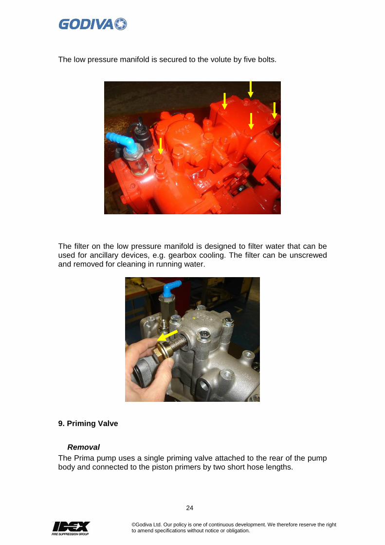
Below the high/low pressure filter housing, the low pressure manifold is secured to the volute by five bolts.
The filter in the high/low pressure housing is designed to prevent large particles from entering the high pressure stage. During pump operation in low pressure mode and at any time the pressure relief valve is open, a flow of water is directed across the filter helping to flush the exterior of the filter. The change over valve is clamped between the filter housing and the bypass connector housing and is retained by four off bolts. Also constrained between the two housings is the cylindrical pressure relief valve and sealed on its outside diameter by two O rings. This valve contains a strong internal spring and must not be stripped down. It is reinstalled with its open end towards the filter housing. It is retained by an external circlip.
Removal – Low pressure manifold
P1 only The low pressure manifold, with filter housing, is attached to the top of the volute.
Removal
To remove this entire assembly disconnect the pressure gauge connections together with any foam connection options that may be fitted.
24
©Godiva Ltd. Our policy is one of continuous development. We therefore reserve the right to amend specifications without notice or obligation.
The low pressure manifold is secured to the volute by five bolts.
The filter on the low pressure manifold is designed to filter water that can be used for ancillary devices, e.g. gearbox cooling. The filter can be unscrewed and removed for cleaning in running water.
9. Priming Valve
Removal
The Prima pump uses a single priming valve attached to the rear of the pump body and connected to the piston primers by two short hose lengths.

25
©Godiva Ltd. Our policy is one of continuous development. We therefore reserve the right to amend specifications without notice or obligation.
1. Disconnect the priming pipes (A) from the priming valve. 2. The priming valve can be removed from the pump as a complete
assembly by undoing the nuts on the two studs (B). 3. To dismantle the priming valve undo the two bolts (D)
Remove the priming valve cover and discard the diaphragm (C). 4. Remove the screw (F) from the piston and separate the piston parts.
Discard the seal (G). 5. Discard the ‘O’ ring (E). 6. Inspect all parts for signs of wear or damage, check that they are in good
condition. Replace damaged parts if necessary. 7. Assemble parts in reverse order, making sure that a new ‘O’ ring (E),
seal (G) and diaphragm (C) are installed. Tighten bolts (D) to complete the unit.
8. Install the priming valve assembly to the pump and secure with the nuts (B) and washers.
9. Connect the priming pipes (A) to the priming valve
10. Primer System – Reciprocating Piston Primer
Removal / Maintenance
The reciprocating piston primer system features two identical pistons located each side of the pump shaft in the bearing housing. Both primers are connected by a flexible hose to the priming valve and through this to the suction tube.
A
B
C
G
E
C
G
E
F
D
B
A

26
©Godiva Ltd. Our policy is one of continuous development. We therefore reserve the right to amend specifications without notice or obligation.
End Cover 1. Disconnect the hose (A).
2. Remove four bolts (B) and washers. Remove the cover (C).
3. The rubber inlet (D p/n 65009) and outlet (E p/n 65008/002) valves must be changed.
4. To replace the valves, remove the screw (F). Remove the valves from the cover.
5. Clean the inside of the cover.
6. Install new valves in the cover. Apply Loctite 380e to the threads of the screw (F). Avoid placing Loctite on the underside of the screw head.
7. Secure the valves with the screw.
A
B
C

27
©Godiva Ltd. Our policy is one of continuous development. We therefore reserve the right to amend specifications without notice or obligation.
Primer Piston and Cylinder These assemblies contain a number of seals that should be replaced.
The piston (G) and cylinder liner (H) assembly comprise two ‘O’ rings (J p/n 65134) and K p/n 61097) and a water seal (L p/n 65119).
1. Replace the two ‘O’ rings and water seal.
2. The water seal and O ring are best replaced using the Godiva special tool P/n 65239/65240 Piston Seal Assembly Tool. This helps to slide the water seal over the edge of the piston.
3. O ring 65134 is placed in the groove of the piston, this is a loose fit. Cone locator 65239 sits on top of the piston, using the piston ring edge as a location guide.
4. Water seal 65119 is placed over the locator at the narrow end. The water seal is placed with the O ring groove facing downwards, so the already fitted O ring can be accommodated. A small amount of water can be used as lubrication around the seal and locator surfaces.
5. Place the seal expander 65240 over the cone with the outer edge pressing down on the water seal.
6. Press down on the seal expander to force the water seal down towards the piston groove. A final push will force the water seal into the piston groove resting on top of the O ring already in the groove.
7. The seal expander and cone locator are now removed.
8. O ring K (p/n 61097) rests in a groove on the outside of the cylinder liner H (p/n 65006/002) and can hand fitted.
G
H
J K
L
M N
P
R S

28
©Godiva Ltd. Our policy is one of continuous development. We therefore reserve the right to amend specifications without notice or obligation.
9. The cylinder body (M) assembly has an outer ‘O’ ring (N) and an inner seal arrangement (P) that comprises three ‘o’ rings, two shaft seals and a wiper carrier. These items are secured in the cylinder bore with a retaining disc (R) and circlip (S).
10. Replace O ring N (p/n 61097) on the cylinder M by pressing the O ring into the groove.
11. To replace the inner seal arrangement P a set of special tools are available to assist correct fitting.
12. First insert the seal (p/n 65159) with its O ring (p/n 65160). It is useful to use the piston shaft as a guidance tool inserted into the cylinder at the reverse side to the working position. Note how the O ring is pointing downwards when inserting in the cylinder.
Piston inserted into reverse side of cylinder to act as seal guide
Seal (65159) with O ring (65160) placed into cylinder recess and hand pushed to bottom

29
©Godiva Ltd. Our policy is one of continuous development. We therefore reserve the right to amend specifications without notice or obligation.
13. Next - the second group of seals (p/n 52816, 65161, 65162) can be prepared for fitting. These three parts locate onto the wiper carrier (p/n 65158/001), a component that should not need replacing.
This picture shows how the seals assemble on the carrier.
Apply a smear of general purpose grease to the O ring A, to assist inserting the assembly into the cylinder.
14. When inserting the seal assembly into the cylinder a suitable press can be used to push the seal to the bottom of the cylinder, using the special tools and retaining disc (p/n 65157) described in section 16 – but without inserting the circlip
15. The seal assembly is retained in the cylinder body by a retaining disc and circlip.
16. To fully insert the seals and O rings use the special tools as indicated in this diagram -
A = O ring p/n 52816 B = Wiper carrier p/n 65158/001 C = seal p/n 65161 D = O ring p/n 65162
The complete assembly is placed in the cylinder using the piston shaft as a location guide.
A B C D

30
©Godiva Ltd. Our policy is one of continuous development. We therefore reserve the right to amend specifications without notice or obligation.
16. Cylinder support tool (p/n 65466) is used to raise the cylinder a short height. 17. Insert the retaining disc (p/n 65167) to rest on top of the previously inserted seals and O ring assemblies. 17. Place the circlip fitting tool (p/n 65436) over the end of piston shaft and resting on the cylinder casting. 18. Insert the circlip (p/n 60914) into the circlip fitting tool.
19. Place the Circlip Drift tool inside the fitting tool to rest on the circlip. By applying pressure to the fitting tool, using a suitable manual press, the circlip will be pushed down until it fits into the groove inside the cylinder liner. This secures and retains the seal assemblies, as below.
31
©Godiva Ltd. Our policy is one of continuous development. We therefore reserve the right to amend specifications without notice or obligation.
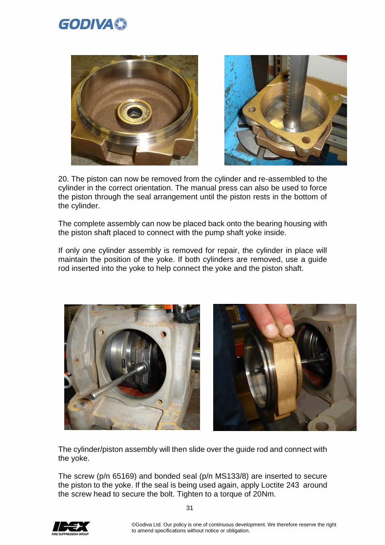
20. The piston can now be removed from the cylinder and re-assembled to the cylinder in the correct orientation. The manual press can also be used to force the piston through the seal arrangement until the piston rests in the bottom of the cylinder. The complete assembly can now be placed back onto the bearing housing with the piston shaft placed to connect with the pump shaft yoke inside. If only one cylinder assembly is removed for repair, the cylinder in place will maintain the position of the yoke. If both cylinders are removed, use a guide rod inserted into the yoke to help connect the yoke and the piston shaft.
The cylinder/piston assembly will then slide over the guide rod and connect with the yoke. The screw (p/n 65169) and bonded seal (p/n MS133/8) are inserted to secure the piston to the yoke. If the seal is being used again, apply Loctite 243 around the screw head to secure the bolt. Tighten to a torque of 20Nm.
32
©Godiva Ltd. Our policy is one of continuous development. We therefore reserve the right to amend specifications without notice or obligation.
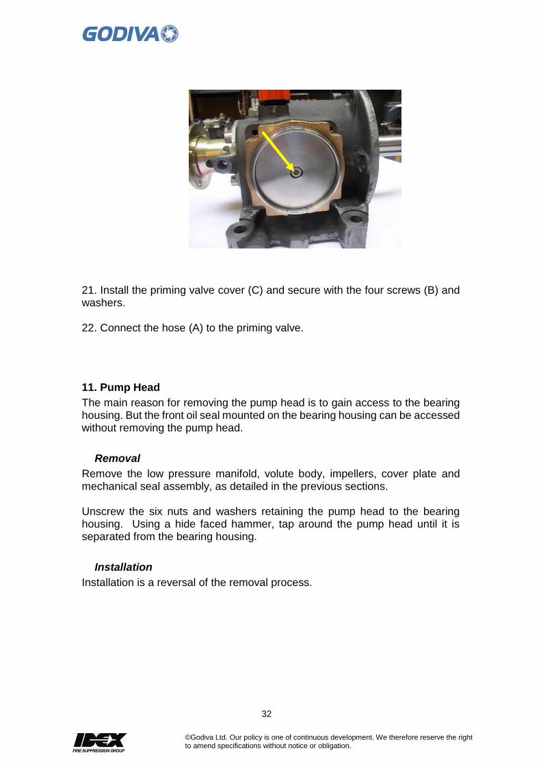
21. Install the priming valve cover (C) and secure with the four screws (B) and washers. 22. Connect the hose (A) to the priming valve.
11. Pump Head
The main reason for removing the pump head is to gain access to the bearing housing. But the front oil seal mounted on the bearing housing can be accessed without removing the pump head.
Removal
Remove the low pressure manifold, volute body, impellers, cover plate and mechanical seal assembly, as detailed in the previous sections. Unscrew the six nuts and washers retaining the pump head to the bearing housing. Using a hide faced hammer, tap around the pump head until it is separated from the bearing housing.
Installation
Installation is a reversal of the removal process.

33
©Godiva Ltd. Our policy is one of continuous development. We therefore reserve the right to amend specifications without notice or obligation.
12. Front End Oil Seal
Removal
To access the front end oil seal, remove the low pressure impeller, cover plate, high pressure impeller and mechanical seal and other relevant sections. Remove the seal housing by undoing the four cap screws.
Installation
When re-fitting, insert a new oil seal into the seal housing. Secure the seal housing with the four cap screws.
12. Rear Oil Seal
Removal
For access to the rear end shaft and oil seal it is necessary to disconnect the drive shaft from the pump drive flange and drain oil from the bearing housing.
Installation
When re-fitting, insert a new oil seal into the seal housing. Secure the seal housing with the four cap screws.
13. Bearing Housing
The following section will only be necessary if worn or damaged bearings or a faulty clutch are suspected.
Removal
Remove from the bearing housing all the assemblies mentioned in previous sections, leaving the bearing housing as a separate module. Drain the bearing housing of all oil. Remove the front and rear oil seal housings. Lightly tap the shaft assembly with a hammer, forwards from the rear (drive flange end), the entire assembly will move forward and free of the bearing housing. The shaft assembly can be dissembled by reversing the assembly process described below. To remove the components on the shaft it is necessary to remove the bearing inner race (at the drive flange end). This can be removed by using a special extractor tool that grips the flinger assembly behind the bearing inner race.

34
©Godiva Ltd. Our policy is one of continuous development. We therefore reserve the right to amend specifications without notice or obligation.
The shaft assembly is set upright on a work bench. By turning the extractor tool the flinger assembly is moved up the shaft and the bearing inner race is pulled away from the shaft.
Note: the majority of the components will slide off the shaft (flinger assembly, shims, balance weight/sliders/yoke/eccentric assembly) but the clutch rotor/stator and two shaft bearings require careful separartion. To remove the clutch rotor from the stator it may be necessary to lever it away from the stator with a suitable tool.
The clutch stator can now be forced off the shaft using a suitable press tool or tapping with a soft headed hammer around the outer edge.
Lever here to remove clutch rotor
35
©Godiva Ltd. Our policy is one of continuous development. We therefore reserve the right to amend specifications without notice or obligation.
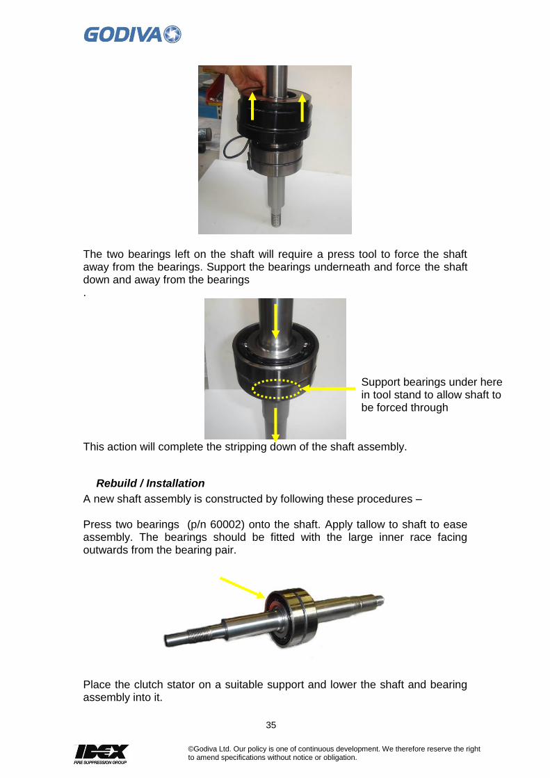
The two bearings left on the shaft will require a press tool to force the shaft away from the bearings. Support the bearings underneath and force the shaft down and away from the bearings .
This action will complete the stripping down of the shaft assembly.
Rebuild / Installation
A new shaft assembly is constructed by following these procedures – Press two bearings (p/n 60002) onto the shaft. Apply tallow to shaft to ease assembly. The bearings should be fitted with the large inner race facing outwards from the bearing pair.
Place the clutch stator on a suitable support and lower the shaft and bearing assembly into it.
Support bearings under here in tool stand to allow shaft to be forced through

36
©Godiva Ltd. Our policy is one of continuous development. We therefore reserve the right to amend specifications without notice or obligation.
Fit the lip seal (p/n 60012) into the seal housing (p/n 65019/001). Place the O ring (p/n 65171) on the seal housing.
Secure the seal housing to the clutch stator with 6 off MS164/20 screws. Apply Loctite 243 to the threads and torque to 20Nm.
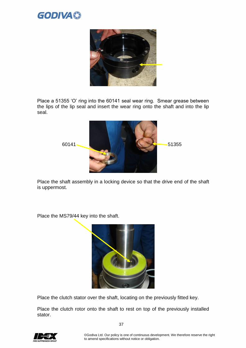
Fit the 53526 ‘O’ ring onto the outside of 65017/004 clutch stator.
37
©Godiva Ltd. Our policy is one of continuous development. We therefore reserve the right to amend specifications without notice or obligation.
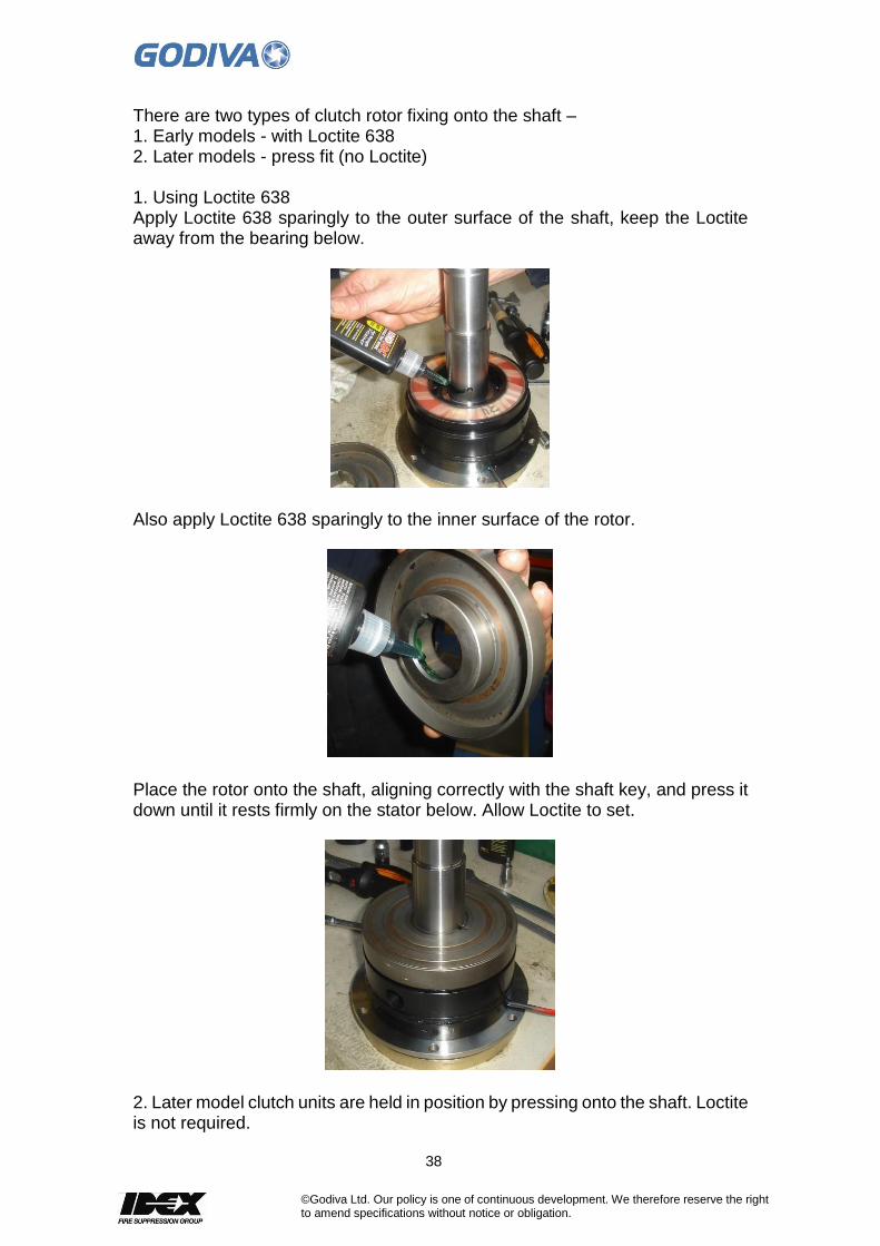
Place a 51355 ‘O’ ring into the 60141 seal wear ring. Smear grease between the lips of the lip seal and insert the wear ring onto the shaft and into the lip seal.
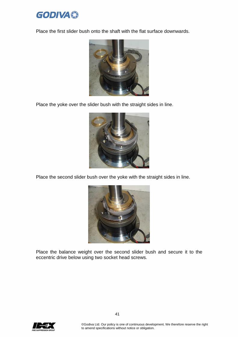
Place the shaft assembly in a locking device so that the drive end of the shaft is uppermost. Place the MS79/44 key into the shaft.
Place the clutch stator over the shaft, locating on the previously fitted key.
Place the clutch rotor onto the shaft to rest on top of the previously installed stator.
51355 60141
38
©Godiva Ltd. Our policy is one of continuous development. We therefore reserve the right to amend specifications without notice or obligation.
There are two types of clutch rotor fixing onto the shaft – 1. Early models - with Loctite 638 2. Later models - press fit (no Loctite) 1. Using Loctite 638 Apply Loctite 638 sparingly to the outer surface of the shaft, keep the Loctite away from the bearing below.
Also apply Loctite 638 sparingly to the inner surface of the rotor.
Place the rotor onto the shaft, aligning correctly with the shaft key, and press it down until it rests firmly on the stator below. Allow Loctite to set.
2. Later model clutch units are held in position by pressing onto the shaft. Loctite is not required.

39
©Godiva Ltd. Our policy is one of continuous development. We therefore reserve the right to amend specifications without notice or obligation.
Turn the assembly over 180° and into a suitable press plate hole.
Press down on the shaft (low force of 20kN) until the stator is fully home.
Using a suitable press tool insert the 56949/008 DU bush into the 65021/005 eccentric drive. The bush should be pushed through the balance weight so it is slightly below or flush with the rear face.
DU bearing slightly below rear face of eccentric drive

40
©Godiva Ltd. Our policy is one of continuous development. We therefore reserve the right to amend specifications without notice or obligation.
Secure the clutch friction plate (part of 65017/004) to the eccentric drive using the (3) screws and washers supplied by clutch manufacturer. Apply Loctite 243 to the threads, Tighten to a torque of 28Nm. Then measure the distance between the surface of the friction plate and the lower surface of the eccentric drive. The measurement will be approximately 4.0 – 4.1mm. Note this measurement.
A gap of 0.24/0.40mm is required between the clutch rotor and friction plate. Selection of an appropriate shim from the table at the end of this section will give the required gap. E.g. gap is 4.1mm, add .3mm for the gap, therefore a shim of 4.4mm is required. A shim of 4.4mm is green coded. See table on page 42.
The previously assembled eccentric drive and friction plate can now be lowered over the shaft onto the clutch rotor face. Check the gap between the friction plate and rotor, it should be 0.3mm.
Next proceed to add the slider bush, yoke and balance weight components.
41
©Godiva Ltd. Our policy is one of continuous development. We therefore reserve the right to amend specifications without notice or obligation.
Place the first slider bush onto the shaft with the flat surface downwards.
Place the yoke over the slider bush with the straight sides in line.
Place the second slider bush over the yoke with the straight sides in line.
Place the balance weight over the second slider bush and secure it to the eccentric drive below using two socket head screws.
42
©Godiva Ltd. Our policy is one of continuous development. We therefore reserve the right to amend specifications without notice or obligation.
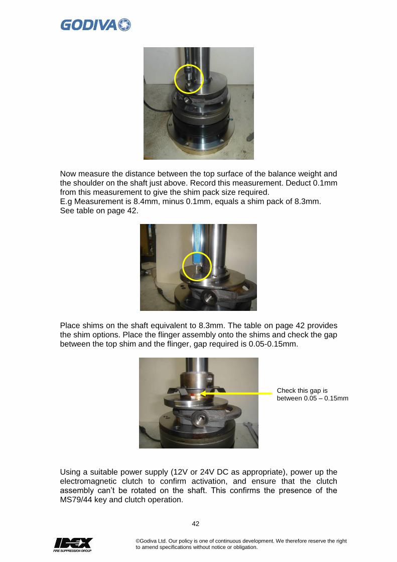
Now measure the distance between the top surface of the balance weight and the shoulder on the shaft just above. Record this measurement. Deduct 0.1mm from this measurement to give the shim pack size required. E.g Measurement is 8.4mm, minus 0.1mm, equals a shim pack of 8.3mm. See table on page 42.
Place shims on the shaft equivalent to 8.3mm. The table on page 42 provides the shim options. Place the flinger assembly onto the shims and check the gap between the top shim and the flinger, gap required is 0.05-0.15mm.
Using a suitable power supply (12V or 24V DC as appropriate), power up the electromagnetic clutch to confirm activation, and ensure that the clutch assembly can’t be rotated on the shaft. This confirms the presence of the MS79/44 key and clutch operation.
Check this gap is between 0.05 – 0.15mm
43
©Godiva Ltd. Our policy is one of continuous development. We therefore reserve the right to amend specifications without notice or obligation.
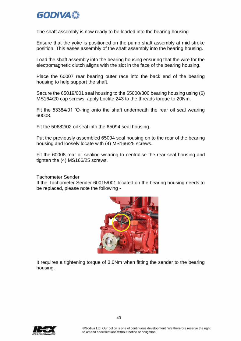
The shaft assembly is now ready to be loaded into the bearing housing Ensure that the yoke is positioned on the pump shaft assembly at mid stroke position. This eases assembly of the shaft assembly into the bearing housing. Load the shaft assembly into the bearing housing ensuring that the wire for the electromagnetic clutch aligns with the slot in the face of the bearing housing. Place the 60007 rear bearing outer race into the back end of the bearing housing to help support the shaft. Secure the 65019/001 seal housing to the 65000/300 bearing housing using (6) MS164/20 cap screws, apply Loctite 243 to the threads torque to 20Nm. Fit the 53384/01 ‘O-ring onto the shaft underneath the rear oil seal wearing 60008. Fit the 50682/02 oil seal into the 65094 seal housing. Put the previously assembled 65094 seal housing on to the rear of the bearing housing and loosely locate with (4) MS166/25 screws. Fit the 60008 rear oil sealing wearing to centralise the rear seal housing and tighten the (4) MS166/25 screws. Tachometer Sender If the Tachometer Sender 60015/001 located on the bearing housing needs to be replaced, please note the following -
It requires a tightening torque of 3.0Nm when fitting the sender to the bearing housing.
44
©Godiva Ltd. Our policy is one of continuous development. We therefore reserve the right to amend specifications without notice or obligation.
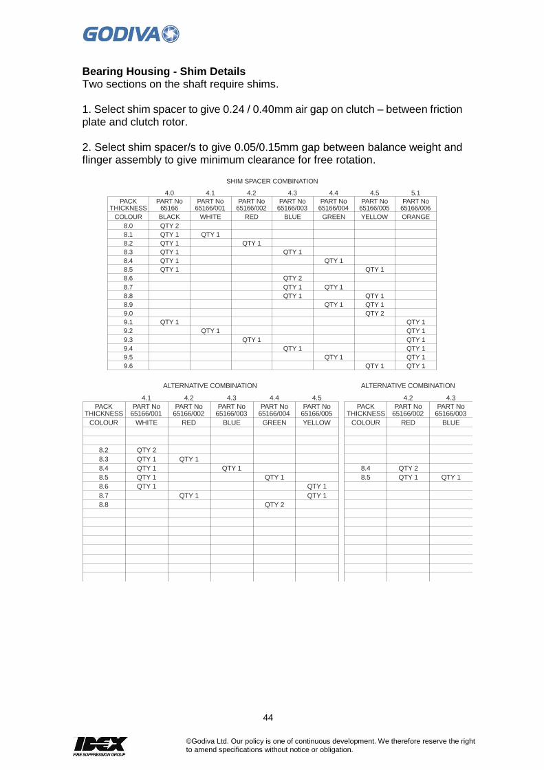
Bearing Housing - Shim Details Two sections on the shaft require shims. 1. Select shim spacer to give 0.24 / 0.40mm air gap on clutch – between friction plate and clutch rotor. 2. Select shim spacer/s to give 0.05/0.15mm gap between balance weight and flinger assembly to give minimum clearance for free rotation.
THICKNESS
8.0
9.6
9.5
9.4
9.3
9.2
9.1
9.0
8.9
8.8
8.7
8.6
8.5
8.4
8.3
8.2
8.1
PACK65166
QTY 2
4.0 4.1
QTY 1
PART No65166/002 65166/003 65166/00665166/00565166/004
QTY 1
QTY 1
QTY 1
QTY 1
QTY 1
QTY 2
QTY 2
QTY 1
QTY 1
QTY 1
QTY 1
QTY 1QTY 1
QTY 1 QTY 1
QTY 1QTY 1
QTY 1 QTY 1
QTY 1QTY 1
QTY 1 QTY 1
QTY 1 QTY 1
QTY 1QTY 1
QTY 1
4.2 4.3 5.14.54.4
PART No PART No PART NoPART NoPART No65166/001
QTY 1
PART No
COLOUR BLACK ORANGEYELLOWGREENBLUEREDWHITE
SHIM SPACER COMBINATION
THICKNESS THICKNESS
8.8
8.7
8.6
8.5 8.5
8.4 8.4
8.3
8.2
PACK PACK
4.1
65166/002 65166/00265166/003 65166/00365166/00565166/004
QTY 1
QTY 2
QTY 1
QTY 1QTY 1
QTY 1QTY 1
QTY 1QTY 1
QTY 1
QTY 1 QTY 1
QTY 1
QTY 2
QTY 2
4.2 4.24.3 4.34.54.4
PART No PART NoPART No PART NoPART NoPART No65166/001PART No
COLOUR COLOURYELLOWGREENBLUE BLUERED REDWHITE
ALTERNATIVE COMBINATIONALTERNATIVE COMBINATION
45
©Godiva Ltd. Our policy is one of continuous development. We therefore reserve the right to amend specifications without notice or obligation.
14. Gearbox (Optional)
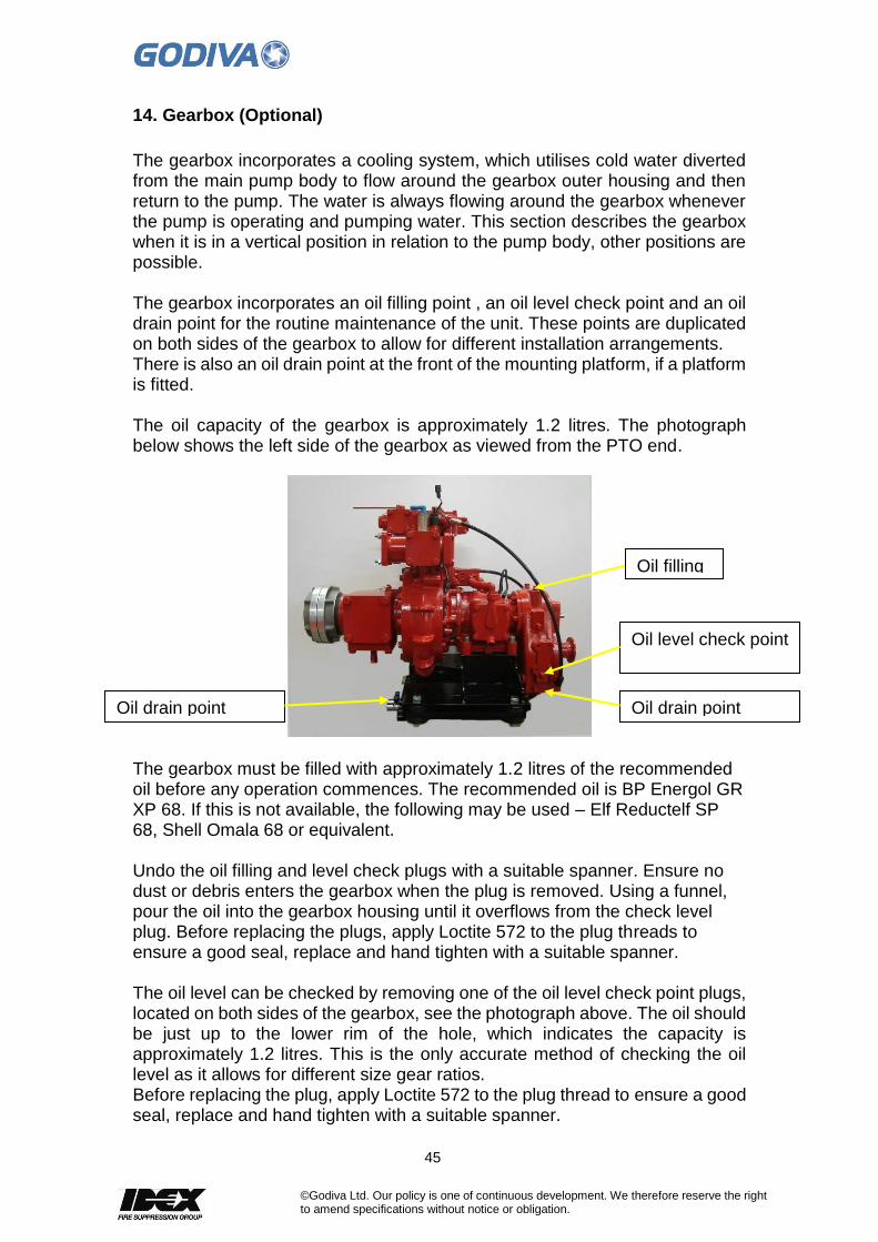
The gearbox incorporates a cooling system, which utilises cold water diverted from the main pump body to flow around the gearbox outer housing and then return to the pump. The water is always flowing around the gearbox whenever the pump is operating and pumping water. This section describes the gearbox when it is in a vertical position in relation to the pump body, other positions are possible. The gearbox incorporates an oil filling point , an oil level check point and an oil drain point for the routine maintenance of the unit. These points are duplicated on both sides of the gearbox to allow for different installation arrangements. There is also an oil drain point at the front of the mounting platform, if a platform is fitted. The oil capacity of the gearbox is approximately 1.2 litres. The photograph below shows the left side of the gearbox as viewed from the PTO end.
The gearbox must be filled with approximately 1.2 litres of the recommended oil before any operation commences. The recommended oil is BP Energol GR XP 68. If this is not available, the following may be used – Elf Reductelf SP 68, Shell Omala 68 or equivalent. Undo the oil filling and level check plugs with a suitable spanner. Ensure no dust or debris enters the gearbox when the plug is removed. Using a funnel, pour the oil into the gearbox housing until it overflows from the check level plug. Before replacing the plugs, apply Loctite 572 to the plug threads to ensure a good seal, replace and hand tighten with a suitable spanner. The oil level can be checked by removing one of the oil level check point plugs, located on both sides of the gearbox, see the photograph above. The oil should be just up to the lower rim of the hole, which indicates the capacity is approximately 1.2 litres. This is the only accurate method of checking the oil level as it allows for different size gear ratios. Before replacing the plug, apply Loctite 572 to the plug thread to ensure a good seal, replace and hand tighten with a suitable spanner.
Oil filling
Oil level check point
Oil drain point
Oil drain point
46
©Godiva Ltd. Our policy is one of continuous development. We therefore reserve the right to amend specifications without notice or obligation.
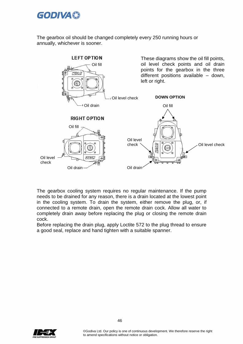
The gearbox oil should be changed completely every 250 running hours or annually, whichever is sooner.
The gearbox cooling system requires no regular maintenance. If the pump needs to be drained for any reason, there is a drain located at the lowest point in the cooling system. To drain the system, either remove the plug, or, if connected to a remote drain, open the remote drain cock. Allow all water to completely drain away before replacing the plug or closing the remote drain cock. Before replacing the drain plug, apply Loctite 572 to the plug thread to ensure a good seal, replace and hand tighten with a suitable spanner.
These diagrams show the oil fill points, oil level check points and oil drain points for the gearbox in the three different positions available – down, left or right.
Oil fill
Oil level check
Oil drain
Oil fill
Oil level check
Oil drain
Oil fill
DOWN OPTION
Oil level check
Oil drain
Oil level check
47
©Godiva Ltd. Our policy is one of continuous development. We therefore reserve the right to amend specifications without notice or obligation.
15. Water Ring Primer (Optional)
The Water Ring Primer is available as an alternative to the Piston Primer system. It is mounted above the bearing housing and driven by a fibre wheel (47) in contact with a pulley at the end of the main pump shaft. Operation of the Water Ring Primer is fully automatic, when the pump is started the primer is driven by the pulley wheel turning the fibre wheel, air is evacuated from the pump allowing water to enter and build water pressure inside the volute. The water pressure inside the pump is then used, via the redundant piston primer housing, to act on a lever which pivots, and through a second lever (61), lifts the Water Ring Primer clear of the drive pulley on the pump shaft. When the primer disengages from the pulley it stops operating, if the pump pressure falls e.g. when the pump is turned off, the primer fibre wheel will re-engage with the pulley ready for priming operation when the pump is started again.
To Remove
To remove the entire Water Ring Primer unit, slacken the hose clip (19) retaining the 3/4inch hose to the top of the primer. Disconnect the hose and secure the hose end away from the primer. Disconnect and remove the primer return spring (62) from the lower part of the primer. If connected, remove the air outlet connection from the top and the water inlet connection from the bottom of the primer. Slacken the two screws (79, 80) securing the primer to the hinge pin (69). Carefully ease the primer unit off the primer hinge pin.
Maintenance
To dismantle the primer for internal inspection, remove the 10 bolts (38) securing the primer bearing housing (54) to the primer body (1). Remove the primer bearing housing complete with shaft, bearings, impeller and pulley. Examine the inner diameter of the impeller (12) and the corresponding surface of the suction and delivery cover (6) for excessive scoring, renewing these parts if necessary. To fit a new suction and delivery cover (6), remove the self-locking screws (7) which secure the cover plate (5) to the suction and delivery cover (6). Fit this cover plate to the new part, noting that no gasket is used but jointing compound should be used on the contacting faces. To fit a new impeller (12), undo the impeller retaining screw (10) and pull off the impeller. Note: if the impeller binds on the shaft it will be necessary to remove the primer shaft as follows - At the pulley end of the shaft, knock back the tabwasher (49) and remove the nut (50) securing the pulley to the shaft. Remove the pulley and extract the woodruff key (41) and the circlip (46). Tap out the shaft (40) from the impeller end. The shaft will bring the bearings (42, 45) with it and these can now be replaced if necessary. The shaft seal (13) will remain in position and if this requires renewing it should be drifted out, together with its backing washer (14), towards the impeller end.

48
©Godiva Ltd. Our policy is one of continuous development. We therefore reserve the right to amend specifications without notice or obligation.
49
©Godiva Ltd. Our policy is one of continuous development. We therefore reserve the right to amend specifications without notice or obligation.
When fitting a new seal ensure that the lip on the backing washer and the open end of the seal face is towards the impeller. To fit a new friction drive pulley (47), remove the pulley from the shaft as detailed above, undo the four nuts, bolts and washers (51, 52, 53) securing the pulley to the centre piece. Fit the new pulley. Refitting of the pulley assembly is a reversal of the dismantling instructions. Ensure that a new tab washer (49) is always used on re-assembly. To examine the non-return valve on top of the primer, undo the four bolts and washers retaining the priming valve inlet (20) to the valve body (26) and cover (30). Examine the seals (23, 25), spring (27) and diaphragm (30) for wear, if necessary replace these parts.
To Refit
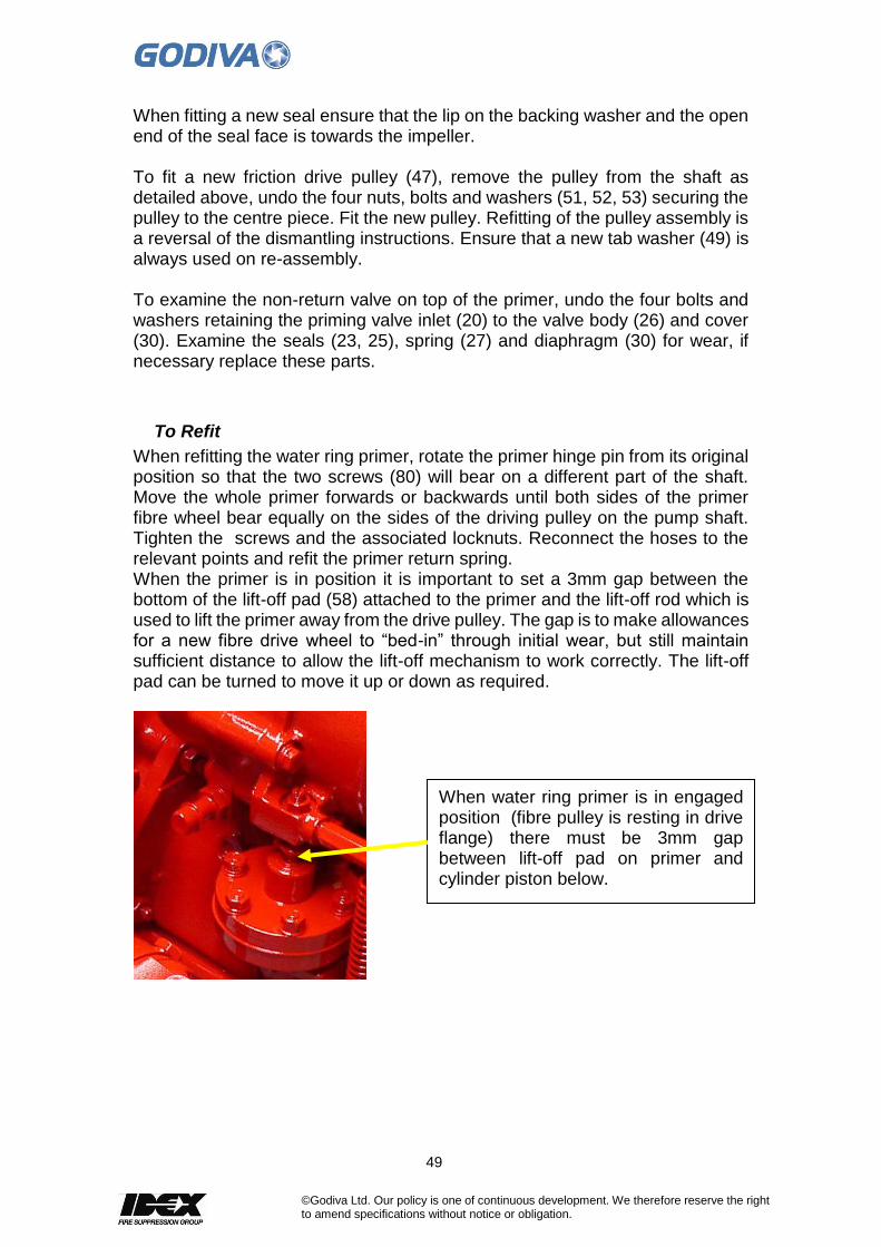
When refitting the water ring primer, rotate the primer hinge pin from its original position so that the two screws (80) will bear on a different part of the shaft. Move the whole primer forwards or backwards until both sides of the primer fibre wheel bear equally on the sides of the driving pulley on the pump shaft. Tighten the screws and the associated locknuts. Reconnect the hoses to the relevant points and refit the primer return spring. When the primer is in position it is important to set a 3mm gap between the bottom of the lift-off pad (58) attached to the primer and the lift-off rod which is used to lift the primer away from the drive pulley. The gap is to make allowances for a new fibre drive wheel to “bed-in” through initial wear, but still maintain sufficient distance to allow the lift-off mechanism to work correctly. The lift-off pad can be turned to move it up or down as required.
When water ring primer is in engaged position (fibre pulley is resting in drive flange) there must be 3mm gap between lift-off pad on primer and cylinder piston below.

50
©Godiva Ltd. Our policy is one of continuous development. We therefore reserve the right to amend specifications without notice or obligation.
16. Pump Tests
Vacuum Test
Place the blanking cap(s) in position on the inlet(s) of the pump and close the delivery valves. Run the pump at 1300-1500 rpm and observe the vacuum/compound needle. When a vacuum of 0.81bar is obtained, stop the pump. This vacuum should be maintained for at least 15 seconds or drop no more than 0.07bar in a minute. If the pump will not hold the vacuum with the blanking caps in position, a leak is present in the pump, and the pressure test detailed below must be carried out to trace it. Should the pump not reach a vacuum of 0.81bar but will hold a lower pressure, a fault in the priming system is indicated.
Pressure Test
This test is to be carried out if the pump will not hold a vacuum with blanking cap(s) in position, and is intended to trace the leaks responsible for the loss of vacuum. Apply a water pressure of 3.5 - 7.0 bar to the pump and check for leaks. The area causing the leak should be visible, and can be dismantled and rectified. Check each primer drain hole for water leakage. If leakage is found, replace the primer seals and O rings as described in the Maintenance Manual Procedures. If the pump will not achieve 0.81 bar vacuum, and will not hold what it does achieve, there is a leak, and possibly also a fault, in the priming system. If no leaks are apparent, the leakage must lie between the priming valve and the primer. Points to be checked are: The inlet seal in the primer end cap The priming valve diaphragm
Water Ring Primer (optional priming system)
If a water ring primer is fitted carry out the same vacuum test as described above but run the pump at 2300rpm to achieve a vacuum. Should the pump not reach a vacuum of 0.78bar but will hold a lower pressure, a fault in the priming system is indicated. Check as follows – See that the primer drive (fibre pulley) is engaged with the pump pulley and runs without slipping Check that the primer is filled with water Check the primer seal drain hole for leakage. If leakage is found, fit a new seal to the primer. If the pump will not hold a vacuum apply the pressure test (as above) and check for leaks. Defective joints and seals must be replaced. If no leaks are apparent, the leakage must be in the line from form the priming valve to the water ring primer, points to be checked are the priming valve sealing washer, the water ring primer non-return valve and the rubber hose and clip.

51
©Godiva Ltd. Our policy is one of continuous development. We therefore reserve the right to amend specifications without notice or obligation.
Pressure Relief Valve (PRV) and Thermal Relief Valve (TRV) Test
With the pump primed, and HP operation selected, close all discharges. Run the pump at approximately 2800rpm. The HP stage pressure should not exceed 50bar if the PRV is working satisfactorily. Continue running the pump, to permit it to heat up. The TRV should open and discharge water when the pump temperature is about 48°C (for a Standard 42°C TRV, for a 74°C it will open about 80°) . Observe the discharge, if it open to atmosphere, or feel the discharge pipe become warm if it returns to the vehicle tank. Open a pump discharge valve to permit cool water to enter the pump. The flow from the TRV should now cease. If the TRV is not operating as it should follow this procedure –
Thermal Relief Valve Maintenance
The Thermal Relief Valve (TRV) fitted usually requires minimum maintenance attention, but should the valve be failing to open at the specified temperature or remaining open after the water temperature has lowered, follow these instructions to clean the valve. 1. Location. The TRV is located on the top surface of the discharge manifold –
2. Remove the TRV with a suitable adjustable spanner to grip the main TRV body.

52
©Godiva Ltd. Our policy is one of continuous development. We therefore reserve the right to amend specifications without notice or obligation.
3. Remove the internal parts from the outer housing. Secure the TRV vertically in a vice. With an adjustable spanner undo the top part of the TRV.
4. The TRV internal parts will now slide out of the housing
5. The thermal actuator (p/n 57053) can now be pushed out of the main housing from the cone end for inspection
6. All the main internal parts can now be inspected for wear and/or the build-up of mineral deposits. If there is significant deposit build-up, this can be removed by cleaning the outer housing and internal parts in a proprietary lime scale remover.
Thermal actuator, p/n 57053
Housing p/n 60806
Seal p/n UFP2303/10
Elbow p/n 59392
O ring p/n 51894 inside cone
53
©Godiva Ltd. Our policy is one of continuous development. We therefore reserve the right to amend specifications without notice or obligation.
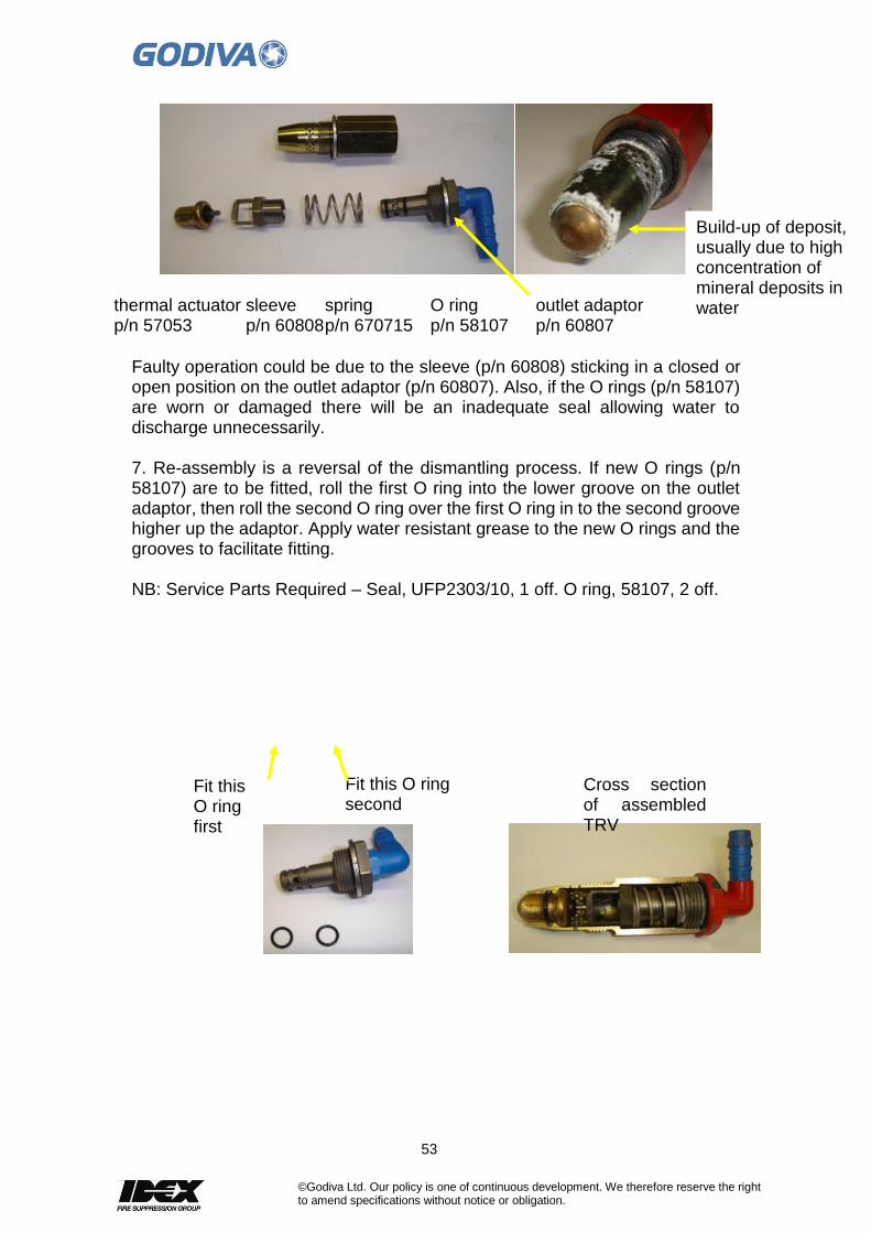
Faulty operation could be due to the sleeve (p/n 60808) sticking in a closed or open position on the outlet adaptor (p/n 60807). Also, if the O rings (p/n 58107) are worn or damaged there will be an inadequate seal allowing water to discharge unnecessarily. 7. Re-assembly is a reversal of the dismantling process. If new O rings (p/n 58107) are to be fitted, roll the first O ring into the lower groove on the outlet adaptor, then roll the second O ring over the first O ring in to the second groove higher up the adaptor. Apply water resistant grease to the new O rings and the grooves to facilitate fitting. NB: Service Parts Required – Seal, UFP2303/10, 1 off. O ring, 58107, 2 off.
Build-up of deposit, usually due to high concentration of mineral deposits in water thermal actuator sleeve spring O ring outlet adaptor
p/n 57053 p/n 60808 p/n 670715 p/n 58107 p/n 60807
Fit this O ring first
Fit this O ring second
Cross section of assembled TRV

54
©Godiva Ltd. Our policy is one of continuous development. We therefore reserve the right to amend specifications without notice or obligation.
Suction Pressure Relief Valve Maintenance
The Suction Pressure Relief Valve (SPRV, p/n 60388) is fitted to the Prima multi-pressure pump. We recommend that the SPRV is checked for correct operation every 12 months, regardless of the amount of pump use. The valve is designed to protect the main parts of the pump from a sudden build-up of internal pressure from the closing of HP discharge hoses at the nozzle end. The valve will open at 13 Bar to allow the discharge of a small amount of pressurised water and close when the pressure drops below this point. The valve is pre-set at the factory to open at 13 Bar and we recommend that valves failing to meet this specification are replaced as a unit. Follow this procedure for checking the valve, especially the valve spring - IMPORTANT: Ensure the pump PTO is disengaged and the pump is drained before proceeding.
1. Remove the rubber discharge pipe by undoing the hose clip.
2. Insert a wire through the hole on the end of the valve. The wire must be sufficiently strong to pull against the internal spring of the valve.

55
©Godiva Ltd. Our policy is one of continuous development. We therefore reserve the right to amend specifications without notice or obligation.
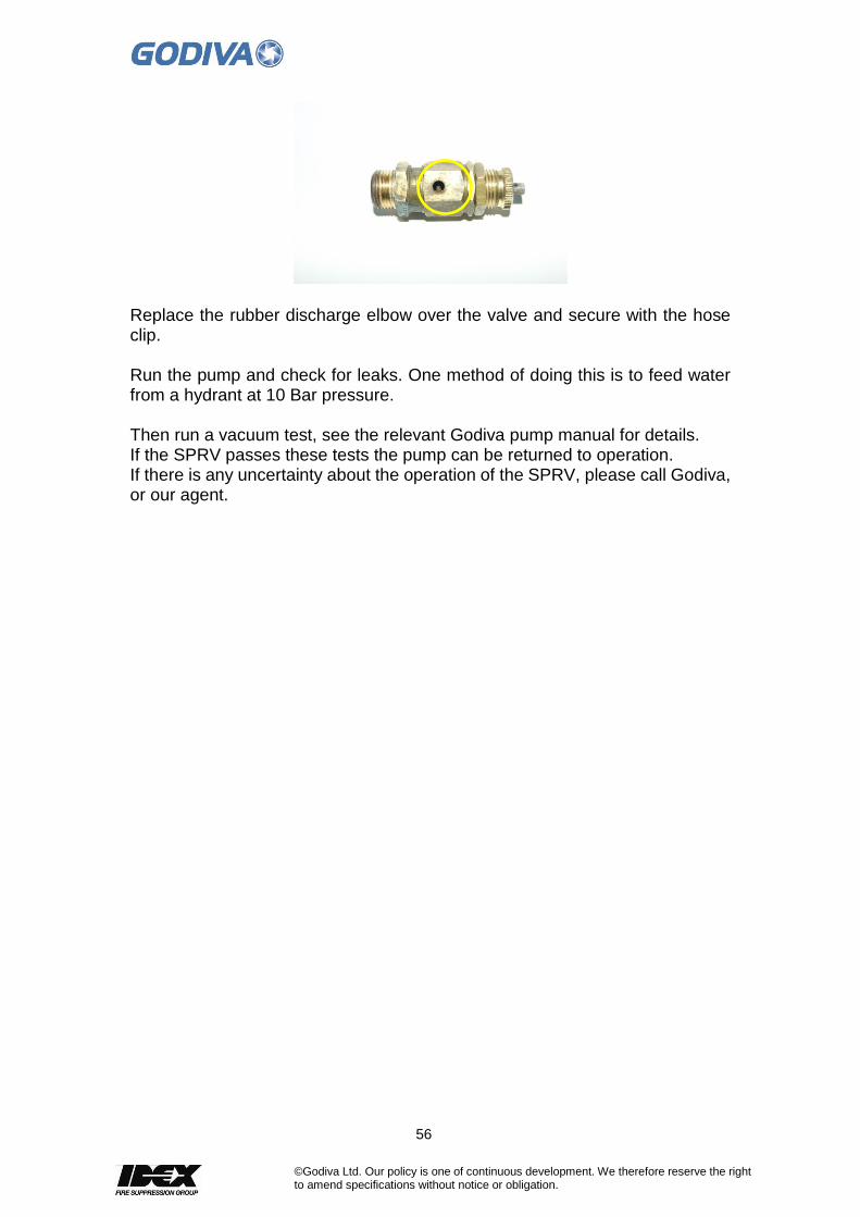
3. If the valve is functioning correctly and free of corrosion, the valve can be pulled outward against the spring - by approximately 3mm and will re-seat when released. Notice the aperture opening on the left of the valve in this picture. This is where the pressurised water will discharge through if it reaches 13 bar or more.
4. If the valve spring is not corroded and functioning correctly it will look like this photograph. There is a small hole in the side of the valve to observe the condition of the spring.
5. A corroded valve spring will look similar to this photograph. If the valve is sticking or the spring corroded, it is necessary to replace the valve completely. Unscrew the valve from the pump and insert a new one - part number 60388.
56
©Godiva Ltd. Our policy is one of continuous development. We therefore reserve the right to amend specifications without notice or obligation.
Replace the rubber discharge elbow over the valve and secure with the hose clip. Run the pump and check for leaks. One method of doing this is to feed water from a hydrant at 10 Bar pressure. Then run a vacuum test, see the relevant Godiva pump manual for details. If the SPRV passes these tests the pump can be returned to operation. If there is any uncertainty about the operation of the SPRV, please call Godiva, or our agent.

57
©Godiva Ltd. Our policy is one of continuous development. We therefore reserve the right to amend specifications without notice or obligation.
17. Delivery Valves
Ball Valve Type
The ball valve should not be dismantled unless it is functioning unsatisfactorily. There are two possible faults and the method of correcting them is as follows: 1. Water leaking round the ball This is due to the O Ring not pressing tightly enough against the ball. Remove the bolts and spring washers and separate the coupling end tube from the ball valve housing. Turn the O Ring over so that it presents a new face to the Ball Valve, or fit a new O Ring. Rub a little Molybdenum Disulphide Powder into the surface of the ball where it contacts the O Ring. Leave the original washers or the same thickness of new washers, between the faces of the coupling end tube and the valve housing. In the case of old valves which have seen extremely arduous service, it may be necessary to fit a new ball, pivot or valve stem. To do this, remove the screw securing the valve stem cap to the ball valve housing and lift off the handle assembly. Remove the nut on the underside of the valve housing and push the ball pivot pin towards the centre of the ball. Remove the spring and take out the two half-rings securing the valve stem. Push out the valve stem and withdraw the ball. Fit the new part required and reassemble, reversing the above procedure. Use a right angled screwdriver to hold the pivot pin when tightening the pivot pin nut. Ensure that the handle is fitted in the correct position. Fit the stem O Ring and ensure that the two half rings are correctly positioned. 2. Water leaking up the valve stem If this occurs, remove the handle and stem as in "1" above and fit a new valve stem O Ring, rubbing a little molybdenum Disulphide Powder into the bore of the valve stem cap.

58
©Godiva Ltd. Our policy is one of continuous development. We therefore reserve the right to amend specifications without notice or obligation.
1 Valve Stem 9 Spring
2 Valve Stem Seal 10 Coupling Release Cap
3 Valve Housing 11 Release Cam
4 Ball Valve 12 Closure Disc
5 Ball pivot and Spring 13 Operating Handle
6 O Ring 14 Circlip
7 Coupling End Tube 15 Joint Washers
8 Coupling Release Bolt
Part Nos
Light Alloy I/C
Gunmetal I/C
LH TH137 TH153/100
RH TH138 TH154/100

59
©Godiva Ltd. Our policy is one of continuous development. We therefore reserve the right to amend specifications without notice or obligation.
Screw-down Type
Godiva Part Number 56544/01 Light Alloy and 56544/05 Gunmetal (Instantaneous Connector Versions)
ITEM DESCRIPTION QTY.
1 Main Body N/A
2 Inlet N/A
3 Outlet 1
4 Pivot Pin 1
5 ‘O’ Ring 2
6 Circlip 2
7 Screw Down Handle 1
8 Domed Nut 1
9 Spring Washer 1
10 ‘O’ Ring 1
11 Screw Down Spindle 1
12 M12 Stainless Steel Washer 1
13 Non Return Flap 1
14 Non Return Flap Washer 1
15 Retaining Washer 1
16 Washer Insert 2
17 Instantaneous Washer 1
18 Twist Release Knob 1
19 Release Cam 1
20 Release Spring 1
21 Release Plunger 1
22 Knob Closure Bung 1
23 Nyloc Nut 1
24 ‘O’ Ring 1
25 ‘C’ Sunk Screw 2
26 Plain Washer 1
27 Moly Grease 1
28 M12 Stainless Steel Nyloc Nut 1

60
©Godiva Ltd. Our policy is one of continuous development. We therefore reserve the right to amend specifications without notice or obligation.
Inspection and Maintenance 1. After each use - Check that the valve opens and closes freely without the need to exert excessive torque to the handwheel. Do not overtighten in either direction. If stiff, dismantle the spindle and investigate. Check that there are no leaks around the spindle. If leaking, change O ring (9). Check that the twist release mechanism operates freely and that the female instantaneous seal is in place. Check visually for any damage. 2. Every three months - Fully open the valve and, using a torch, examine the non return flap rubber sealing washer (14) If damaged or worn, replace the rubber sealing washer. To do this it is first necessary to remove the outlet adaptor, (2) see page 3, section 1, for instructions. Then remove one of the circlips (5) and withdraw the pivot pin (3). The flap (13) can then be extracted from the valve. Replace the rubber sealing washer (14) and plastic inserts (16). Apply Loctite 222 to the screw threads before hand tightening. Reassemble by reversing the above instructions. Fully close the valve, and using a small brush, apply Lithium EP21 plus Moly Grease to the exposed spindle threads. If the spindle stop is the old roll pin type replace with the latest Nyloc nut type. If the spindle is of the latest Nyloc nut type check that the nut is still tight, and that the spindle protrudes through the nut. DO NOT ATTEMPT TO UNSCREW IT (ANTI-CLOCKWISE) UNLESS THE NUT IS TO BE CHANGED. If the spindle end has worn flush with the nut it should be replaced immediately. Check there is no leakage from the flap pivot pin O rings (4) and change if necessary. Grease pivot pin (3) and check that the non return flap is free to articulate. Check that circlips (5) are firmly in place. 3. Every two years - Remove the spindle (see instructions page 3), regrease it, fit a new Nyloc nut (12) and O ring (9) and refit. Inspect the twist release mechanism components and instantaneous seal for damage or corrosion and replace as necessary.

61
©Godiva Ltd. Our policy is one of continuous development. We therefore reserve the right to amend specifications without notice or obligation.
Screw down valve
Screw down valve, view through the connector showing the spindle with the Nyloc nut and washer fitted to the end of the spindle.
Instructions for Removing / Changing Spindles The spindle retaining nut may be removed and replaced by accessing through the instantaneous coupling. Access is much easier if the coupling is removed, but this will take longer. 1. With the valve still bolted to the pump, remove the outlet adaptor. To do this dismantle the twist release mechanism, taking care to retain all components. Using a soft mallet strike the cam boss so that the adaptor turns anti-clockwise. Note: Alternatively special spanners are available to enable the adaptor to be removed without dismantling the twist release mechanism, see photograph below. If a storz connector is fitted this may also need a special spanner to remove from the valve body.
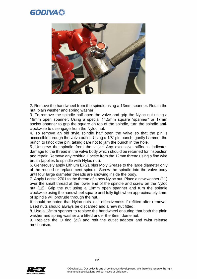
62
©Godiva Ltd. Our policy is one of continuous development. We therefore reserve the right to amend specifications without notice or obligation.
2. Remove the handwheel from the spindle using a 13mm spanner. Retain the nut, plain washer and spring washer. 3. To remove the spindle half open the valve and grip the Nyloc nut using a 19mm open spanner. Using a special 14.5mm square “spanner” or 17mm socket spanner to grip the square on top of the spindle, turn the spindle anti-clockwise to disengage from the Nyloc nut. 4. To remove an old style spindle half open the valve so that the pin is accessible through the valve outlet. Using a 1/8” pin punch, gently hammer the punch to knock the pin, taking care not to jam the punch in the hole. 5. Unscrew the spindle from the valve. Any excessive stiffness indicates damage to the thread in the valve body which should be returned for inspection and repair. Remove any residual Loctite from the 12mm thread using a fine wire brush (applies to spindle with Nyloc nut). 6. Generously apply Lithium EP21 plus Moly Grease to the large diameter only of the reused or replacement spindle. Screw the spindle into the valve body until four large diameter threads are showing inside the body. 7. Apply Loctite 2701 to the thread of a new Nyloc nut. Place a new washer (11) over the small thread at the lower end of the spindle and screw on the Nyloc nut (12). Grip the nut using a 19mm open spanner and turn the spindle clockwise using the handwheel square until fully tight when approximately 4mm of spindle will protrude through the nut. It should be noted that Nyloc nuts lose effectiveness if refitted after removal. Used nuts should always be discarded and a new nut fitted. 8. Use a 13mm spanner to replace the handwheel ensuring that both the plain washer and spring washer are fitted under the 8mm dome nut. 9. Replace the O ring (23) and refit the outlet adaptor and twist release mechanism.

63
©Godiva Ltd. Our policy is one of continuous development. We therefore reserve the right to amend specifications without notice or obligation.

64
©Godiva Ltd. Our policy is one of continuous development. We therefore reserve the right to amend specifications without notice or obligation.
Continental Delivery Valves
1 Body, incl. Nipple
3 Spindle
4 Guide Sleeve
4.1 O-Ring
5 X-Ring
6 Guide Axle Complete
7 Tap Washer
8 Valve Plate Complete
9 Tap Washer
10 Compression Spring
11 Release Knob Assembly
12 Handwheel
13 Washer
65
©Godiva Ltd. Our policy is one of continuous development. We therefore reserve the right to amend specifications without notice or obligation.
14 Cap Nut
Function The valve opens and closes by turning the handwheel anti-clockwise and clockwise respectively and has an integrated, automatic non-return device. The handwheel should be opened until the spindle travels against the stop and then twisted half a turn in the opposite direction. When the pump is temporarily stopped, the non-return valve keeps the delivery hose filled and prevents the water in the hoses from draining via the pump inlet. To drain filled delivery hoses, especially when hoses are connected to a dry riser at buildings, pull Release Knob (11). The handwheel may now be turned further in the opening direction and water is allowed to drain via the pump.
Maintenance The spindle should be greased (lubricated) on a quarterly basis, using a proprietary waterproof grease such as Shell Retinex A or equivalent. Caution When opening the valve do not force the handwheel against its stop. NB. Max. working pressure is 16bar.

66
©Godiva Ltd. Our policy is one of continuous development. We therefore reserve the right to amend specifications without notice or obligation.
Instantaneous Connector Servicing Procedure:
Item Description
1 Twist release bolt
2 Self-lock pin
3 Spring, twist release
4 Nyloc nut
5 Closure disc / red plug
6 Twist release knob
7 Twist release cam
8 2½” FM Twist release body
9 2½” Instantaneous seal
Inspection A. Flush out equipment with clean water after use B. Inspect equipment monthly and follow maintenance procedures at least
once every year C. Inspect release mechanism for free movement D. Inspect the rubber seal Maintenance If signs of wear or breakdown of the mechanism occur, strip down and replace parts as follows: 1. Remove Knob Closure Disc 5. If the disc is of plastic type, insert pointed
tool into hole in disc and prise out. If the disc is metal, use an Ajax ladder key locating in the 2 holes in the disc and unscrew anti-clockwise.
2. Unscrew nut 4 using a socket spanner and Knob 6 can then be removed. 3. Withdraw Bolt 1 and Spring 3 from the inside of the female instantaneous
body. 4. Check for signs of dirt, wear or corrosion of the Spring, clean the parts and
reassemble. If wear has occurred replace the affected parts with spares. 5. Reassemble the mechanism by reversing the foregoing instructions using
a lubricating grease on the Spring and the Bolt. 6. When tightening Nut 4 the tension on the spring is correct when the
leading edge of the curved face of Bolt 1 is level with the bolt hole edge as shown in diagram above.
7. Check Seal 9 for dirt, cuts or damage to seal lip after cleaning. If damaged, replace with spare seal.
Special Notes
The recommended lubricant for the bolt and spring is Molybdenum Disulphide Grease (Lithium Grease)
Always use a new locknut when reassembling the mechanism.
5
4
3
2
1
6
7
8
9

67
©Godiva Ltd. Our policy is one of continuous development. We therefore reserve the right to amend specifications without notice or obligation.
17. Tightening Torques
Part Description Torque
Nm Lbs ft MS164/20 65019/001 Seal Housing to Clutch Stator 20 15
NPN 65017/004 Friction plate to eccentric drive. (Clutch manufacturers supply)
28 21
MS166/25 65094 Seal housing to bearing housing 20 15
MS165/35 65040 Cover plate to pump head 44 32
65405 65004 Rear wear ring to cover plate 10 7.5
MS164/25 65078 Front wear ring to suction tube 12 9
65181 Impeller retaining nut 300 225
MS07/35 Drive flange retaining screw 103 76
65169 Screw retaining piston primer to yoke in bearing housing 20 15
60015/001 Tachometer sender, tightening into bearing housing 3 2.2
18. Special Tools
Part For Piston Primer Equipped Pumps
Description
60275/03 Clamping spacer
65486 Mechanical seal extraction tool
65239 Piston seal assembly tool – cone locator
65240 Piston seal assembly tool – seal expander
65436 Circlip fitting tool – piston primer seal replacement
65466 Cylinder support tool – piston primer seal replacement
65467 Circlip drift - piston primer seal replacement
Part For Water Ring Primer Pumps
Description
60275/03 Clamping spacer
65486 Mechanical seal extraction tool

68
©Godiva Ltd. Our policy is one of continuous development. We therefore reserve the right to amend specifications without notice or obligation.
19. Adhesives, Solvents and Greases List
The following is a summary of the adhesives, solvents and greases required and the area of application.
Page reference Location Adhesive
12 Front wear ring, securing to suction tube
Loctite 243. Tighten to 12Nm.
14 Inside bore of low pressure impeller
Tallow
15 Rear wear ring, securing to pump head or cover plate
Loctite 243. Tighten to 12Nm.
18 HP cover plate, auto drain ball plate, 2 off screws
Loctite 243
18 HP cover plate to pump body, under head of capscrews
Molykote 37. Tighten to 44Nm
19 Mechanical seal assembly, inserting into pump head or impeller
Soft soap solution
25 Piston primer – screw retaining inlet and outlet valves
Loctite 380e
28 Piston primer – o ring (52816) on piston shaft
General purpose grease
31 Piston to yoke, 2 off screws
Loctite 243. Tighten to 20Nm
34 Bearing housing. Fitting bearings to shaft, 2 off.
Tallow
35 Seal housing to clutch stator
Loctite 243. Tighten to 20Nm.
37 Clutch rotor to shaft, inner surface. Early type of assembly only.
Loctite 638
39 Clutch friction plate to eccentric drive, 3 off screws
Loctite 243. Tighten to 28Nm
42 Seal housing to bearing housing, 6 off cap screws
Loctite 243. Tighten to 20Nm
44, 45 Gearbox – drain plugs, oil level check plugs
Loctite 572
52 TRV – o rings on actuator Water resistant grease
53 Delivery valve, ball type. Valve ball and stem.
Molybdenum disulphide powder
57 Delivery valve,
continental type. Spindle
Shell Retinax A or equivalent
58 Instantaneous connector bolt and spring
Molybdenum Disulphide grease (Lithium grease)