pricing scenario #2 - u.s. communities scenario #2 drawings and details provides detailed...
TRANSCRIPT

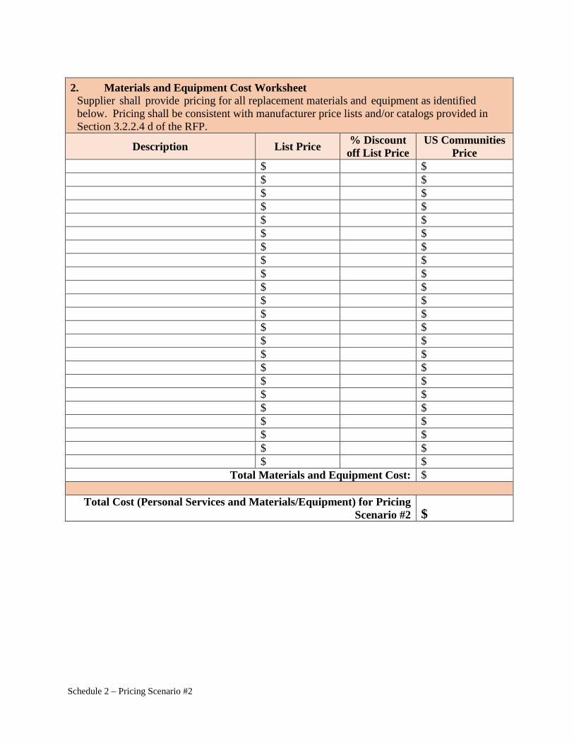
Schedule 2 – Pricing Scenario #2
SCHEDULE 2 PRICING SCENARIO #2
Variable Frequency Drives and Unitary HVAC Equipment
Description The project consists of the installation of Variable Frequency AC Drives (VFDs) and a rooftop-mounted packaged air-conditioning unit. Pricing Scenario #2 Drawings and Details provides detailed information about the replacement equipment. Instructions Supplier must provide all personal services classifications, billing rates, materials and equipment costs, for Pricing Scenario #2 below. Classifications and billing rates shall be consistent with the rates provided in Section 3.2.2.4 e of the RFP. Do not include labor costs associated with trade services or the construction installation portion of the Pricing Scenario. Cost Worksheet Pricing is provided for evaluation purposes only and shall not be construed as Supplier’s complete offer.
1. Personal Services Cost Worksheet Please provide a list of all personal services classifications required to execute an Energy Savings Performing Contract, including the billing rate and estimated number of hours.
Position Classification Billing Rate Total Estimated Project Hours Total Cost
$ $ $ $ $ $ $ $ $ $ $ $ $ $ $ $ $ $ $ $ $ $ $ $ $ $ $ $ $ $ $ $ $ $ $ $ $ $ $ $
Total Personal Services Costs $
Schedule 2 – Pricing Scenario #2
2. Materials and Equipment Cost Worksheet
Supplier shall provide pricing for all replacement materials and equipment as identified below. Pricing shall be consistent with manufacturer price lists and/or catalogs provided in Section 3.2.2.4 d of the RFP.
Description List Price % Discount off List Price
US Communities Price
$ $ $ $ $ $ $ $ $ $ $ $ $ $ $ $ $ $ $ $ $ $ $ $ $ $ $ $ $ $ $ $ $ $ $ $ $ $ $ $ $ $ $ $ $ $
Total Materials and Equipment Cost: $
Total Cost (Personal Services and Materials/Equipment) for Pricing Scenario #2 $
1.2
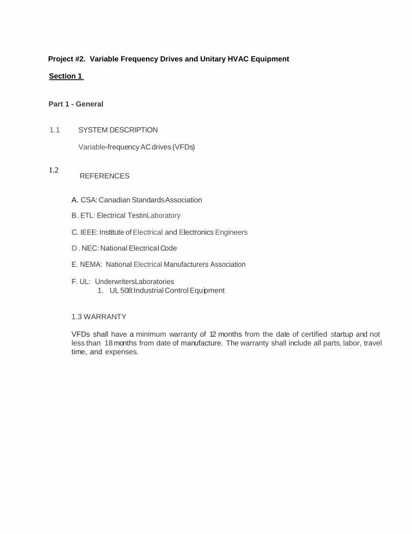
Project #2. Variable Frequency Drives and Unitary HVAC Equipment Section 1
Part 1 - General
1.1
SYSTEM DESCRIPTION Variable-frequency AC drives (VFDs)
REFERENCES
A. CSA: Canadian Standards Association
B . ETL: Electrical TestinLaboratory
C. IEEE: Institute of Electrical and Electronics Engineers
D . NEC: National Electrical Code
E. NEMA: National Electrical Manufacturers Association F. UL: UnderwritersLaboratories
1. UL 508:Industrial Control Equipment
1.3 WARRANTY
VFDs shall have a minimum warranty of 12 months from the date of certified startup and not less than 18 months from date of manufacture. The warranty shall include all parts, labor, travel time, and expenses.

A. Acceptable Manufacturers: Allen Bradley, Robicon, ABB, or pre-bid approved equal.
PART 2 - PRODUCTS
2.1 VARIABLE-FREQUENCY MOTOR CONTROLLERS
A. General Description:
1. AC motor variable frequency controller (VFC) shall be of pulse width modulated (PWM) inverter type. The VFC shall be designed to convert 60 Hz input power to adjustable frequency output power to provide positive speed control to standard induction motors. The VFC shall be dedicated variable torque design for specific use with centrifugal loads.
2. Provide complete solid state variable frequency power and logic unit 3. Frequency control shall be stepless throughout the range under variable torque load on
a continuous basis. Frequency controlled by remote building energy management system providing 4-20MA input signal to drive and remote start/stop signal.
4. Provide adjustable frequency control with diode bridge/capacity input designed to provide high, constant power factor of 0.95 regardless of load or speed and eliminate SCR line noise.
5. Each VFD shall contribute no more than 5 percent total harmonic voltage distortion at the VFD input terminals while operating under full-load conditions. If proposed VFD equipment is anticipated to exceed these limits, multi-pulse converters and/or harmonic filtering devices shall be provided.
6. Equipment shall be designed and manufactured in accordance with applicable current NEMA and IEEE recommendations and be designed for installation in accordance with NEC. Equipment shall have UL and/or CSA approval.
7. Control shall be suitable for operation in ambient temperatures of O to 40"C. 8. Every VFD shall be factory tested with an AC induction motor I00 percent loaded and
temperature cycled within an environmental chamber at 104°F.
C. Self -Protection and Reliability Features: 1. Adjustable current limit from 60 to 110percent of drive rating. 2. Adjustable instantaneous over current trip. 3. Under voltage trip. 4. Over temperature trip. 5. Short circuit protection phase to phase and phase to ground faults phase rotation
insensitive. 6. Momentary power loss, more than 17 milliseconds. 7. Transient protection against all normal transients and surges in incoming power line. 8. Orderly shutdown in event of any of above conditions, drive shall be designed to shut down
safely without component failure. 9. Provide visual indication and manual reset.
D. Standard Features:
I. Drive logic shall be microprocessor based. Control logic shall be isolated from power circuitry.
2. Standalone operation to facilitate startup and troubleshooting procedures. 3. VFD shall have a lockable circuit breaker disconnect and be UL 508C listed for use on
distribution systems with 22,000 AIC. 4. Door interlock protection which shall be defeatable by qualified personnel to
troubleshoot during operation as required. 5. Input power 460V 60 Hz,3-phase output voltages shall be equal to applied input voltage. 6. Isolated signal inputs.

7. Frequency Stability: Output frequency shall be held to +0.1 percent of maximum frequency regardless of load, +10 percent input voltage change or temperature changes within ambient specification.
8. Built-in digital display located in panel face shall indicate output frequency, voltage and current and shall provide indication of over current, over voltage, current limit, ground fault, over temperature, input power on, minimum or maximum speed adjustment, power on, and fault condition.
9. Start/Stop Control: Controlled decelerated stop. 10. Primary and secondary fused for a control circuit transformer. 11. Minimum and maximum speed control. 12. Adjustable Aecel/Deccl: Independently adjustable 10-100 second. 13. Hands-off auto switches. 14. Programmable auto restart after power outage. 15. Fused disconnects shall include auxiliary contacts to isolate control circuit when
disconnect is in "off" position. 16. Remote contacts for fault, and on/off status. 17. Adjustable motor output voltage. 18. Analog output voltage of 0-10 VDC, 4-2-0MA proportional to control output frequency. 19. RS232 communications port, and programming software capability.
E. Additional Features:
I. NEMA I enclosure shall isolate each motor starter and control section with its associated disconnect switch.
2. Manual speed control for each motor. 3. Manual bypass shall provide ability to service control while motor is operational. 4. Provide radio frequency and electromagnetic interference noise suppression network to limit
radio frequency and electromagnetic interference. 5. Provide isolated analog output signals for volts, amps, and frequency, from each VFD for
connection to the building energy management system. 6. Provide line (input) reactors. 7. Provide output filters for all VFD's located more than 150 conductor feet from the motor they
serve. 8. VFD shall be designed to catch a spinning load in forward and reverse direction. 9. Harmonic calculations shall be performed on a manufacturer-supplied harmonic analysis program for conformance with IEEE 519-1992
F. CSA, ETL, or UL label.
END OF SECTION 1
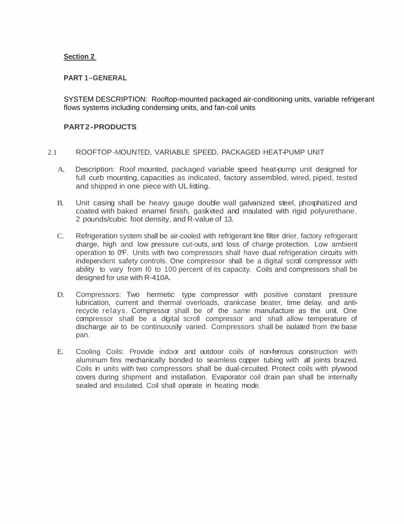
Section 2 PART 1 –GENERAL SYSTEM DESCRIPTION: Rooftop-mounted packaged air-conditioning units, variable refrigerant flows systems including condensing units, and fan-coil units
PART 2 - PRODUCTS
2.1 ROOFTOP-MOUNTED, VARIABLE SPEED, PACKAGED HEAT-PUMP UNIT
A. Description: Roof mounted, packaged variable speed heat-pump unit designed for full curb mounting, capacities as indicated, factory assembled, wired, piped, tested and shipped in one piece with UL listing.
B. Unit casing shall be heavy gauge double wall galvanized steel, phosphatized and
coated with baked enamel finish, gasketed and insulated with rigid polyurethane, 2 pounds/cubic foot density, and R-value of 13.
C. Refrigeration system shall be air-cooled with refrigerant line filter drier, factory refrigerant
charge, high and low pressure cut-outs, and loss of charge protection. Low ambient operation to 0°F. Units with two compressors shall have dual refrigeration circuits with independent safety controls. One compressor shall be a digital scroll compressor with ability to vary from I0 to 100 percent of its capacity. Coils and compressors shall be designed for use with R-410A.
D. Compressors: Two hermetic type compressor with positive constant pressure
lubrication, current and thermal overloads, crankcase beater, time delay, and anti-recycle relays. Compressor shall be of the same manufacture as the unit. One compressor shall be a digital scroll compressor and shall allow temperature of discharge air to be continuously varied. Compressors shall be isolated from the base pan.
E. Cooling Coils: Provide indoor and outdoor coils of non-ferrous construction with
aluminum fins mechanically bonded to seamless copper tubing with all joints brazed. Coils in units with two compressors shall be dual-circuited. Protect coils with plywood covers during shipment and installation. Evaporator coil drain pan shall be internally sealed and insulated. Coil shall operate in heating mode.

G. Wheel Heat Exchanger Section: Wheel shall be mounted in a rigid frame containing drive motor, drive belt, wheel seals and bearings and shall be removable from the unit without the use of tools. Bypass damper shall be installed at wheel on both the supply and exhaust paths. Manufacturers that do not provide integral wheel in main unit cabinet must provide all required mounting curbs, posts, required accessories, fans, pre-filters, dampers and insulated cabinet to provide fully assembled working unit. Sensible energy recovery wheels shall be constructed of lightweight polymer and shall be provided without desiccant coating and shall not degrade nor require additional coatings for application in marine or coastal environments. Segments shall be washable with detergent or alkaline coil cleaner and water.
H. Fans: Indoor fans shall be the centrifugal type, permanently lubricated, belt-
driven by a permanently lubricated motor. Outdoor fans shall be a propeller type direct-driven by a permanently lubricated motor. Provide with vibration isolation, 2-inch deflection.
I. Variable Frequency Motor Controllers: Provide variable frequency
motor controllers as specified.
J. Electrical heat Electric heaters shall be controlled by a SCR (Silicone Controlled Rectifier). Emergency heat is for operation when compressors arc in a defrost cycle. Auxiliary heat is for use to supplement the heating capacity of the unit heat pump.
K. Filters: 2-inch-thick throw-away type filters.
L. Controls: Provide a complete control systems package. Provide analog and digital control points to interface with building control system.
M. Electrical: Furnish magnetic con.tactors, separate fusing for compressors,
condenser fans, and evaporator fans, and control transformer. Arrange unit for single point electrical connection. Provide with factory-mounted unit disconnect.
N. Acoustical Roof Curb: Acoustically treated, formed, 16-gaugc galvanized steel
with wood nailer strip capable of supporting entire unit weight. Provide integral I-inch deflection spring isolation with flexible weather seal.
2.2 VARIABLE REFRIGERANT FLOW SYSTEM

A. Indoor Unit (FCU)- Ceiling Concealed Ducted : 1. Description: The unit shall be a ceiling-concealed ducted fan coil designed to
mount above the ceiling with a 2-position, field adjustable return and a fixed horizontal discharge supply. Furnish complete unit including cabinet, mounti.ng kit and accessories, refrigerant line set, electronic expansion valve, fan and motor assembly, cooling coil, condensate drain pan, filter and filter housing. Unit as scheduled on drawing, factory- tested and assembled, factory wired, refrigerant-to-air beat exchanger, fan/motor assembly, compressor, controls and safety devices, control circuit transformer, shipped in one piece with ARI certification and UL listing. Unit model selection shall be made after clearance limitations are field verified.
2. Cabinet: The cabinet shall be space saving, ceiling-concealed, ducted and shall have provisions for a field installed filtered outside air intake. Constructed of 18 gauge steel, removable panels for access to components. Provide drain connection.
3. Fan and Motor: The evaporator fan shall be an assembly with one or two lines-flow fan(s) direct driven by a single motor. The fan shall be statically and dynamically balanced and run on a motor with permanently lubricated bearings. The fun shall consist of two (2) speeds, High and Low.
4. Coil/Piping: The indoor coil shall be direct expansion type of nonferrous construction with smooth plate fins on copper tubing. A condensate pan shall be located under the coil. Both refrigerant lines shall be insulated.
5. Filter: Provide return filter box with high-efficiency MERV-13 filters. 6. Electrical: Furnish all starters, contactors and disconnects. Arrange for single
point electrical connection. 7. Condensate Pump: Provide condensate lift pump for each unit Condensate pumps
shall be powered from Fan Coil.
B.. VRF Controls: I. Provide a complete, factory-installed VRF control system with all operating and
safety controls, consisting of remote controllers and centralized controllers. Network together using a high-speed communication bus and wiring as recommended by manufacturer. Provide all control wiring for a complete and operational system. Provide Control Interface hardware to allow communication between the VRF system and the Building Control system. Provide all required controllers for stand-alone temperature sensors. The controls network to support operation monitoring, scheduling, error email distribution, personal browsers, and online maintenance support.
2. Standard Room Thermostat: Simple MA Remote Controller, with ability to allow the user to change on/off, temperature setting, and fan speed setting. The room temperature shall be sensed at either the Simple MA Remote Controller or the Indoor Unit dependent on the indoor unit dipswitch setting. Use a PAC remote sensor to replay space temperature from the space where adjustable thermostats are not allowed. Remote sensor shall not display or allow changes to any settings. Provide display of a four-digit error code in the event of system abnormality/error.

3. Centralized Controller: Capable of controlling via a PC a maximum of 50 indoor units with multiple outdoor units. The Centralized Controller shall able to override remote controllers every 2 hours, system configuration, daily/weekly/annual scheduling, monitoring of operation status, error email notification, online maintenance tool and malfunction monitoring. Provide basic operation controls which can be applied to an individual indoor unit, a group of indoor units (up to 50 indoor units),or all indoor units (collective batch operation) including on/off, operation mode selection (cool, heat, auto, dry, and fan), temperature setting, fan speed setting, airflow direction setting, error email notification, and online maintenance.
4. Power Supply: Provide 12V power supply for centralized controllers.
C. Outdoor Unit: I. Description:
a. Provide air cooled heat pump (with heat recovery system for simultaneous heating and cooling) designed for outdoor installation with factory supplied supports, properly assembled and tested at the factory.
b. Unit shall be completely weatherproofed and include compressor, condenser coils, condensing fans, motor, refrigerant reservoir, charging valve, all controls and a holding charge of refrigerant
c. Provide guards on condenser fans and coil guard. Unit shall have a power coated finish.
d. Unit shall be completely factory assembled, piped, wired and tested. c. Both refrigerant lines shall be insulated between the outside and inside units. f. Unit shall have a sound rating no higher than 63 dB(A). g. The units shall be modular in design and allow for side-by-side installation
with minimum spacing. h. Provide accessories and kits required for a complete installation including
field connection of heat pump units. 2. Cabinet: The casing(s) shall be fabricated of galvanized steel, bonderized and
finished with baked enamel. 3. Condenser Fans and Motors: Direct driven variable speed propeller type fans
with permanently lubricated motors. All fans shall be provided with a raised guard to prevent contact with moving parts. The outdoor unit shall have vertical discharge airflow.
4. Refrigerant Circuits: Units shall hold a charge of R4I0A refrigerant. Unit shall include back seating service valve and gauge ports in liquid and suction lines. Provided refrigerant filter-dryer. The refrigeration circuit of the condensing unit shall consist of a scroll compressor, motors, fans, condenser coil, electric expansion valve, solenoid valves, 4-way valve, distribution headers, capillaries, filters, shut-off valves, oil separators, service ports, liquid receivers and accumulators.
5. Coil: The outdoor coil shall be of nonferrous construction with lanced or corrugated plat fins on copper tubing.

6. Compressors: Furnish inverter driven scroll hermetic sealed compressor isolation and sound muffling. Units shall have overload and inherent winding thermostat protection to prevent burn out. Provided crankcase beater. Multiple compressors shall be manifolded for single joint connection on liquid and suction lines. The capacity shall be completely variable down to 16% of rated capacity.
7. Controls: Provide high and low pressure cutouts, contractors and internal overload protection on all motors. Provide low ambient operation to 0°F outside to maintain condensing temperature on part load operation. Provide short cycle timer.
8. Controls: Complete, factory-installed control system with all operating and safety
controls. Include all remote sensors and devices for field installation.
9. Warranty: Provide five year warranty on all compressors.
D. Branch Circuit Controller: 1. General: The unit shall have a galvanized steel finish. The BC Controller shall be
completely factory assembled, piped and wired. Each unit shall be run tested at the factory. This unit shall be mounted indoors. Unit shall operate so that different zones served by each controller can be in heating and cooling mode simultaneously.
2. Cabinet: a. The casing shall be fabricated of galvanized steel. b. Each cabinet shall house a liquid-gas separator and multiple refrigeration
control valves. c. The unit shall contain tube-in-tube heat exchangers.
3. Refrigerant Valves: a. The unit shall be furnished with multiple two position refrigerant valves. b. Each circuit shall have a two-position liquid line valve and a two-position
suction line valve. c. When connecting a 54,000 BTU-h or larger indoor unit section, two branch circuits
shall be joined together at the branch controller to deliver an appropriate amount of refrigerant. The two refrigerant valves shall operate simultaneously.
d. Linear electronic expansion valves shall be used to control the variable refrigerant flow.
4. Refrigeration Isolation Valves: The unit shall be provided with isolation valves on each port, including spare ports.
5. Integral Drain Pan: An integral condensate pan and drain shall be provided. 6. Controls: The control circuit between the indoor units and the outdoor unit shall
be 24VDC completed using a 2-conductor, twisted pair shielded cable to provide total integration of the system.
7. Condensate pump: Provide condensate pump with bard-wired electrical connection when required.
8. Electrical: Furnish all starters and contactors. Arrange for single point electrical connection.
9. Controls: Complete, factory-installed control system with all operating and safety controls. Include all remote sensors and devices for field installation.
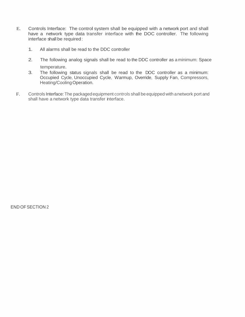
E. Controls Interface: The control system shall be equipped with a network port and shall have a network type data transfer interface with the DOC controller. The following interface shall be required : 1. All alarms shall be read to the DDC controller
2. The following analog signals shall be read to the DDC controller as a minimum: Space
temperature. 3. The following status signals shall be read to the DOC controller as a minimum:
Occupied Cycle, Unoccupied Cycle, Warmup, Override, Supply Fan, Compressors, Heating/Cooling Operation.
F. Controls Interface: The packaged equipment controls shall be equipped with a network port and
shall have a network type data transfer interface.
END OF SECTION 2

PRICING SCENARIO #2 - DRAWINGS AND DETAILS
DISCLAIMER: The contents may not print to scale. 1) CD POX 2012 0501 00 0024 0 SCHEDULES· MECHANICAL EAN: 20110049 Section: M0.03 2) CD POX 2012 0501 00 0034 0 ROOF PLAN- EAST· MECHANICAL EAN: 20110049 Section: M2.05 3) CD POX 2012 0501 00 0036 0 DETAILS· MECHANICAL EAN: 20110049 Section: M5.02 4) SP POX 2012 0003 00 0053 O Variable-Frequency Motor Controllers EAN: 20110049 Section: 232923 5) SP POX 2012 0003 00 0058 O Decentralized Unitary HVAC Equipment EAN: 20110049 Section: 238100
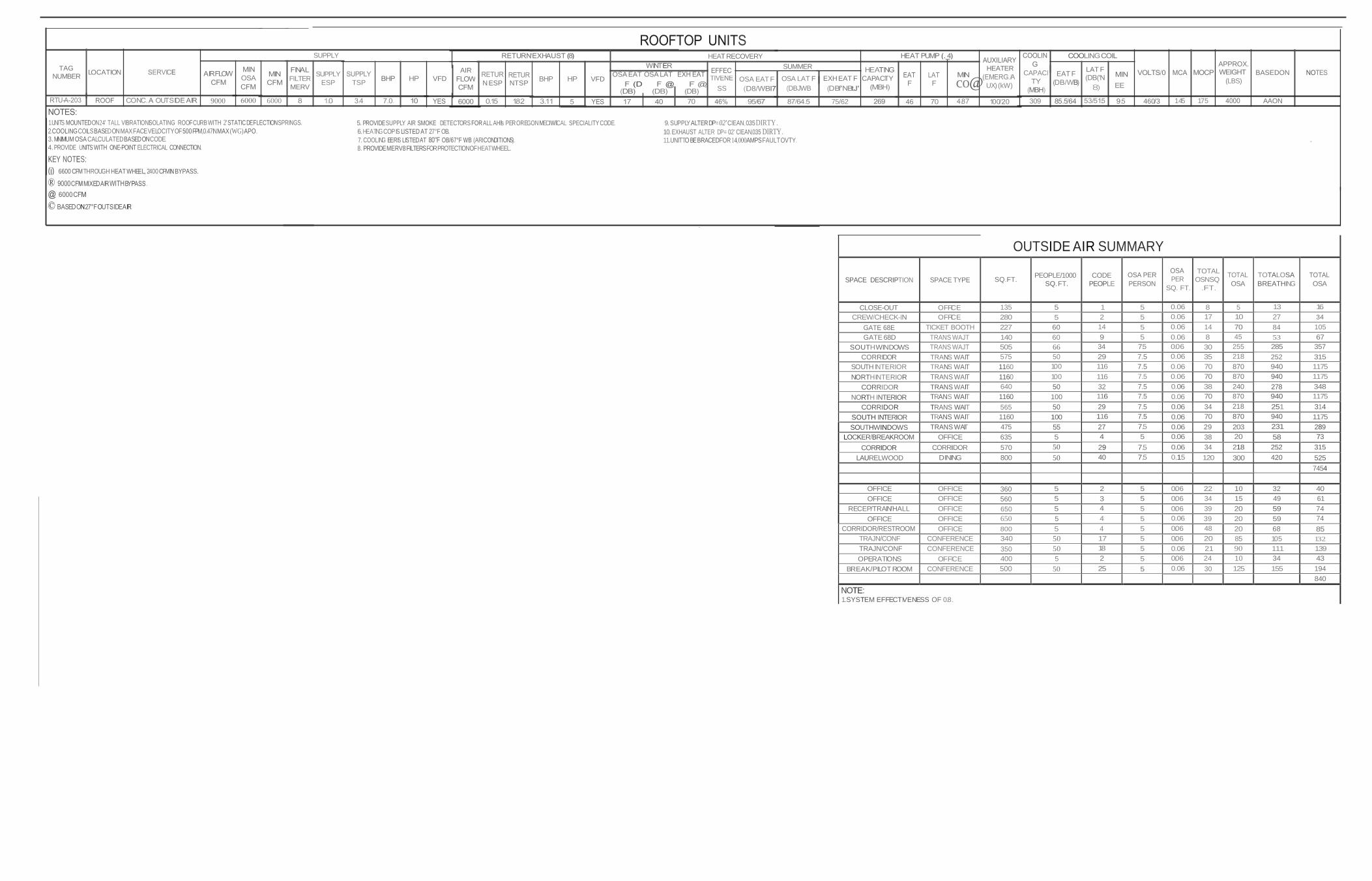
SUPPLY
TAG NUMBER LOCATION
FILTERMERV
SUPPLY ESP
TSP VFD
AIR
HEAT RECOVERY
N ESP
NTSP VFD
OSA EAT OSA LAT
SUMMER
OSA LAT F(DBJWB
EXH EAT F CAPACITY
HEATER
9000 6000
SS
OSA EAT F
75/62
co@ UX) (kW)
46
CAPACI
EAT F
LAT F
APPROX.
BASEDON (LBS)
460/3 145 175 AAON
1.UNITS MOUNTEDON24' TALL VIBRATIONISOLATING ROOFCURB WITH 2'STATICDEFLECTIONSPRINGS. 2.COOLINGCOILS BASEDONMAX FACEVELOCITY OF500 FPM,0.47INMAX (WG) APO.
5. PROVIDESUPPLY AIR SMOKE DETECTORS FORALL AHl!s PEROREGONMECIWllCAL SPECIALITY CODE. 6. HEATING COP IS LISTED AT 27°F OB.
9. SUPPLY ALTER DP= 02' ClEAN,0.35 DIRTY. 10. EXHAUST ALTER DP= 0.2' ClEAN,0.35 DIRTY.
3. MINIMUM OSA CALCULATEDBASEDONCODE. 4. PROVIDE UNITS WITH ONE-POINT ELECTRICAL CONNECTION.
7. COOLING EERIS LISTEDAT 80"F OB/67°F WB (ARICONDITIONS). 8. PROVIDE MERV8 FILTERS FOR PROTECTION OF HEAT WHEEL.
11.UNIT TOBE BRACEDFOR 14,000AMPS FAULT OVTY.
KEY NOTES: (j) 6600 CFMTHROUGH HEAT WHEEL, 2400 CFMIN BYPASS.
OUTSIDE AIR SUMMARY
SPACE DESCRIPTION
SPACE TYPE
SQ.FT.
PEOPLE/1000 SQ. FT.
CODE PEOPLE
OSA PER PERSON
OSA PER
SQ. FT.
TOTAL
OSNSQ .FT.
TOTAL OSA
TOTALOSA BREATHING
TOTAL OSA
CLOSE-OUT OFFICE 135 5 1 5 0.06 8 5 13 16 CREW/CHECK-IN OFFICE 280 5 2 5 0.06 17 10 27 34
GATE 68E TICKET BOOTH 227 60 14 5 0.06 14 70 84 105 GATE 68D TRANS WAJT 140 60 9 5 0.06 8 45 53 67
SOUTHWINDOWS TRANS WAJT 505 66 34 7.5 0.06 30 255 285 357 CORRIDOR TRANS WAIT 575 50 29 7.5 0.06 35 218 252 315
SOUTH INTERIOR TRANS WAIT 1160 100 116 7.5 0.06 70 870 940 1175 NORTH INTERIOR TRANS WAIT 1160 100 116 7.5 0.06 70 870 940 1175
CORRIDOR TRANS WAIT 640 50 32 7.5 0.06 38 240 278 348 NORTH INTERIOR TRANS WAIT 1160 100 116 7.5 0.06 70 870 940 1175
CORRIDOR TRANS WAIT 565 50 29 7.5 0.06 34 218 251 314 SOUTH INTERIOR TRANS WAIT 1160 100 116 7.5 0.06 70 870 940 1175 SOUTHWINDOWS TRANS WAIT 475 55 27 7.5 0.06 29 203 231 289
LOCKER/BREAKROOM OFFICE 635 5 4 5 0.06 38 20 58 73 CORRIDOR CORRIDOR 570 50 29 7.5 0.06 34 218 252 315
LAURELWOOD DINING 800 50 40 7.5 0.15 120 300 420 525
7454
OFFICE OFFICE 360 5 2 5 0.06 22 10 32 40 OFFICE OFFICE 560 5 3 5 0.06 34 15 49 61
RECEP/TRAIN/HALL OFFICE 650 5 4 5 0.06 39 20 59 74 OFFICE OFFICE 650 5 4 5 0.06 39 20 59 74
CORRIDOR/RESTROOM OFFICE 800 5 4 5 0.06 48 20 68 85 TRAJN/CONF CONFERENCE 340 50 17 5 0.06 20 85 105 132 TRAJN/CONF CONFERENCE 350 50 18 5 0.06 21 90 111 139 OPERATIONS OFFICE 400 5 2 5 0.06 24 10 34 43
BREAK/PILOT ROOM CONFERENCE 500 50 25 5 0.06 30 125 155 194
840
NOTE: 1.SYSTEM EFFECTIVENESS OF 0.8.

o
.-N-
& I . I
. I d'<
UJ I . (j)
UJ UJ (j)
U'J z
- -0
.- . ---- - -e
\ TRUE\ NI n.....;RITH.
!
·
LOCATION PLAN SCALE : N T.S.
ROOF PLAN EAST - MECHANICAL 1 SCALE: 1/8" = 1'0" M2.05

g
CONDENSATE PUMP AT FAN COIL
ED SATE
SECTION 283100 FIREALARM CONTROL
PANEL
OPEN @
END SWITCH @
FSD (120V)
1'CD
HEAT TRACEWITH 22 LINEAL FEET OF CHROMALOX SRF OR EQUAL. 8w/LINEAL FOOT HEAT TRACE 120V-1 PHASE INSULATE HEAT TRACED PORTION OF CONDENSATEDRAIN WITH 1" OF FIBERGLASS INSULATIONWrrH VAPOR BARRIER.__ ,
BRICK WALL
CMU WALL
. . DISCHARGE TO MOP SINK OR EXTERIOR AS
SLOPE
KEY NOTE:
CONDENSATE DRAIN MAIN
DOC CONTROL PANEL
SECTION230900 120V
-ii-
FIRE SMOKE DAMPER (FSD) BY SECTION 233300
FDSTO BEPOWERED BYAHUFSD CIRCUIT.
24 v
ST,A.TUS
@
ACCESS PANEL
(SEEARCH)
SHOWN ON PLANS CD PUMPEDCONDENSATE IS NOT SHOWN ON PLANS. REQUIREDAT EACHFAN COILAND BC CONTROLLER.
MINIMUM 12'ABOVE FINISHED GRADE
STATUS FAIL r --------------- DI
EXHAUST AIR
@ SIS @l@ STATUS
SIS @
ALARM
RETURNAIR
SMK DI
\ \
\
STAND ALONE UNIT CONDITIONER
--------OUTSIDE
CONDENSATEDRAIN PAN
EXHAUST DAMPER RETURN/
EXHAUST FAN
....--t lli .-.----- ...--------' u::
::c
MAT
Q)0
ROOF
SUMP ALARM FLOAT SWITCH (INSIDERTU)
T _, 8
SUPPLY FAN
.--Atl--------tl 1-- --.t :z: g w 1--.--i---iu1 -------- i
FIREALARM CONTROL
PANEL ._ _ _ _ _ _ -L------ .
_ _J
OUTSIDEAIR
OUTSIDE @) AIR DAMPER
u:: 1:§
-o@ @DX STAGE 1
I. L_ _
RA ..........
·-·-
VENTILATION SA
OUTSIDEAIR
KEY NOTES:
ALARM \ - @ ox STAGE 2
....._ , \_ BYPASS DAMPER
SMK DI
.CD PROVIDEPER SECTION 606 OFIBELATEST EDITIONOF IBESTATEOF OREGONMECHANICAL SPECIALTY CODE
TYPICALFOR
RTU-A-203 Q)SMOKEDETECTOR FURNISHEDANDWIRED BY DIV.26,INSTALLED IN DUCT BY DIV.23.
(D HARD WIRE IN SISCONTROLCIRCUIT.
SPACE Q)0
SUPPLYAIR
CONDENSATE DRAIN 1 SCALE: NOT TO SCALE M5.02
FIRE/SMOKE DAMPER CONTROL (TYPICAL) 2 SCALE: NOT TO SCALE M5.02
EXTERIOR CONDENSATE DRAIN 5 SCALE: NOT TO SCALE M5.02
SCALE: NOT TO SCALE
f
3/4'PUMP CONDEN
ROOFTOP AIR CONDITIONING UNIT (RTU) CONTROL DIAGRAM 4 SCALE: NOT TO SCALE M5.02