prevention of power outages and forest … avifauna_012018_en.pdf · • implementation of a...
TRANSCRIPT

15kV – 132kV MV/HV NETWORKS.
CA
TAV
IF_0
12
01
8
https://envertec.eu
FOREWORD
GENERAL CONTENTS
PERFORMANCE MONITORING
INTERACTIVE CATALOGUE
BIRD PROTECTION SYSTEMS AND DEVICES· ANTI-ELECTROCUTION· ANTI-PERCHING· ANTI-COLLISION ·
PREVENTION OF POWER OUTAGES AND FOREST FIRES

• An Innovation due to the material used: HTV SILICONE with HYDROPHOBICITY levelHc2/WC2 and Shore A >65 _ FLAMMABILITY TYPE V0 IEC60695-11-10:2013.
TRACK RECORD OF ENVERTEC S.L. IN THIS FIELD.
• Full awareness and expert field knowledge of the existing problems.
• The CAON®-KORWI® brand products were pioneers in this field with thedevelopment in 2011 and 2015 – in collaboration with Spanish utility ENDESADISTRIBUCIÓN ELÉCTRICA – of a specific solution for new power lines:
o Polymer Bird Protection Insulators models C3670EBAV and C3670EBAV_AR .
o More than 20,000 Bird Protection Insulators installed over the past 7 years
with no reported incidents.
• Implementation of a pioneering Quality and Traceability assurance system that was thefirst of its kind in the industry: R+D+I - In-House Design and Engineering, included in thescope of our >> ISO 9001:2015 certification, control of production throughout allstages, traceability of the end product and batch control of the safe raw materials used,allowing the assessment of the product throughout its entire life cycle and properrecycling at the end of its service life CAON®-KORWI® SILICONE COVERS _ PROVEN EFFECTIVENES
• Repels moisture build-up: Optimum performance in Saline Atmospheres.
• Exceptional performance under exposure to UV Radiation: Shows no colourdegradation or crystallisation. >>Ongoing field performance assessment report.
• Withstands high continuous operating temperatures up to 105°C.
• Minimum silicone thickness of 3 -3.5 mm: High Dielectric Strength–Safe Devices.
• Design and type tests carried out with successful results by prestigious officially accredited independent testing laboratories.
• Track record of installed devices in the field: More than 60,000 Pre-Molded
Covers and over 100,000m of bare conductor Covers installed without any incidents in SPAIN– PORTUGAL – MEXICO -
https://envertec.euCATAVIF_012018 [email protected] 2
BIRD PROTECTION SYSTEMS FOR 15kV – 132kV MV / HV NETWORKS
EFFECTIVE SOLUTIONS DESIGNED TO PRESERVE WILDLIFEAND ENSURE A CONTINUOUS POWER SUPPLY.
PRODUCTION FACILITY
ISO 9001 – ISO 140126,000 m2
ENGINEERING DEPARTMENT_ R+D+I Made in Spain.
VERIFIED QUALITY AND PERFORMANCE – SHORT REFERENCES
/ 52

BACKGROUND:
The development of rural areas requires a suitable power distribution and supply network based on medium andhigh voltage lines.
These lines frequently have to run across high environmental value areas (ZEPA).
The natural heritage of the areas affected is an essential pillar of their natural wealth and financial income.
The coexistence of these two factors leads to specific situations that compromise both: Natural Heritage and
Continuous Power Supply , therefore our efforts and developments are focused on
o Electrocution of birds belonging to protected species.
o Forest Fires arising from short circuits caused by bird-related accidents, among others.
o Outages in electric power supply.
BIRD PROTECTION SYSTEMS FOR15kV – 132kV MV / HV NETWORKS
CURRENTLY EXISTING PROBLEMS AND REGULATORY FRAMEWORK.
Effective solutions suitable for new-build systems andsystems currently in operation.
Compliance with applicable legislation and regulations:
o Royal Decree (RD) 1432/2008
o Official Andalusian Government Gazette(BOJA) 209 178/2006 and other regionalRegulations and Utility internal regulations.
o AENOR EA0058: 2016 Specification
o Quality and Traceability assurance for installeddevices. Monitoring of Environmental Impact.
https://envertec.eu3
In view of the currently existing problem and the requirementslaid down in the applicable legislation, ENVERTEC made thecommitment to devote all its technological and industrialinventive capabilities – evidenced by the patents to its name –to developing a range of recyclable and environmentally safeproducts aimed at preserving bird species and preventing poweroutages, both in newly built lines (bird-protection insulators)and in existing lines (polymer spacers and anti-electrocutionprotective covers), for use on high voltage overhead lines. Wewere pioneers in establishing quality parameters, some of whichwere finally included in Specification EA0058:2016 published bySpanish standards body AENOR, where we had the privilege ofbeing invited from the outset – 2014 – to participate in thedrafting of the specification as members of the BIRDPROTECTION WORKING GROUP .
CATAVIF_012018
PROACTIVE EFFORTS BY ENVERTECCURRENT REGULATORY REQUIREMENTS
[email protected] / 52

ISO 9001:2015 CERTIFIED QUALITYRESEARCH, DEVELOPMENT AND INNOVATION. R+D+I
CATAVIF_012018 4 / 52 https://[email protected]

BIRD ANTI-ELECTROCUTION PROTECTION SYSTEMS FOR MV / HV NETWORKS - ANTI-PERCHING AND ANTI-COLLISION DEVICES
General Contents List of Solutions. Regulations: R.D. 1432/2008 - BOJA 209 178/2006 – EA 0058.
POLYMER PHASE SPACERS.USE ON 15-132kV MEDIUM AND HIGH VOLTAGEDISTRIBUTION AND TRANSMISSION OVERHEAD LINES.
RETROFITTING OF EXISTING LINES
CAON-KORWI® SILICONE DEVICES USE ON 15 – 45kV
DISTRIBUTION OVERHEAD LINES.
ANTI-COLLISION AND ANTI-PERCHING DEVICESDESIGNED TO PREVENT BIRD COLLISIONS WITH BARE CONDUCTORS
ON DISTRIBUTION LINES AND PREVENT PERCHING ON POWER SYSTEM
STRUCTURES.
CATAVIF_012018
INSTALLATION IMAGE GALLERY
PRODUCT SUPPLY HIGHLIGHTS
General Contents List of Solutions
NEW LINE CONSTRUCTION AND LINE RETROFITS
CAON®-KORWI® BIRD PROTECTION INSULATORS FOR ZEPA
USE ON 15-36kV DISTRIBUTION LINES.
CERTIFIED QUALITY R + D + I
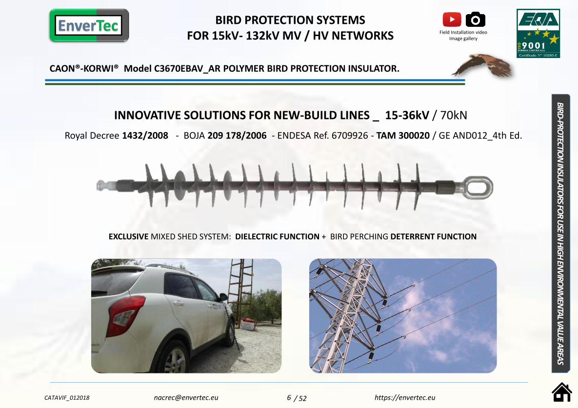
CAON®-KORWI® Model C3670EBAV_AR POLYMER BIRD PROTECTION INSULATOR.
INNOVATIVE SOLUTIONS FOR NEW-BUILD LINES _ 15-36kV / 70kN
Royal Decree 1432/2008 - BOJA 209 178/2006 - ENDESA Ref. 6709926 - TAM 300020 / GE AND012_4th Ed.
EXCLUSIVE MIXED SHED SYSTEM: DIELECTRIC FUNCTION + BIRD PERCHING DETERRENT FUNCTION
BIRD PROTECTION SYSTEMS FOR 15kV- 132kV MV / HV NETWORKS
BIRD-PRO
TECTION
INSU
LATORS
FOR
USE IN
HIG
HEN
VIRO
NM
ENTA
LVALU
EA
REAS
https://envertec.euCATAVIF_012018 [email protected] 6
Field Installation video Image gallery
/ 52

• Model C3670EBAV_AR is an evolved version of the CAON®-KORWI® Model C3670EBAV insulator:
This exclusive revolutionary design by ENVERTEC S.L. is an evolution of model C3670EBAV (more than 14,140 units installed in Spain with zero
incidents), which has been fitted with 12 star-shaped sheds to provide the insulator with UNIQUE ADDITIONAL FEATURES, turning it into a PERCHING
DETERRENT element.
• Excellent Dielectric Performance:
Insulator suitable for MEDIUM VOLTAGE LINES UP TO 36 kV with a Rated Mechanical Load of 70 kN.
•LEVEL IV Leakage path design:
Engineered to achieve a Limited leakage distance to avoid overprotecting the line, through simulations to balance the shed diameters with the total
insulation length provided by this insulator (> 1m) . The result is an Insulator with a Leakage distance of 1,350 mm - VERY HIGH POLLUTION –
AND012, Ed. 4/2015 - and a Protected Leakage Distance >1,000 mm.
Regulations and TYPE APPROVALS
Designed in accordance with Standard UNE-EN 61109:2010 (IEC 61109:2008).
The CAON®-KORWI® model C3670EBAV _AR insulator is the first of its kind to have been type-approved by an electric utility, in this case ENDESA
DISTRIBUCION , according to its regulation GE AND012-4ªEd. Hence, since 23/06/2015 it is an Approved Product with SIE Code No 6709926 – TAM
300020 .
Very easy to INSTALL AND MAINTAIN _ Reduction in Associated Costs
SINGLE-PIECE INSULATOR: Better performance under mechanical stress and reduced insulator string weight (3.16 kg), leading to easier
transport and installation (vs. articulated insulator string).
No need to cover clamps or conductor, preventing moisture build-up due to condensation, and facilitating the detection of Hot Spots and
faults on the conductors. THE MOST ECONOMICAL AND COMPETITIVE SOLUTION FOR COMPLIANCE WITH CURRENT REGULATIONS.
The star-shaped auxiliary sheds protect the insulator from damage by birds (crow family), through their perching deterrent effect, while
also providing a protective barrier for the 5 sheds with a purely dielectric function.
IMPROVED FEATURES AND PERFORMANCE. DESIGN EVOLUTION.
C3670EBAV C3670EBV_AR
BIRD PROTECTION SYSTEMS FOR 15kV- 132kV MV / HV NETWORKS
CATAVIF_012018 7 https://[email protected]
Field Installation video
Image gallery
/ 52

IMPROVED FEATURES AND PERFORMANCE. DIELECTRIC SHEDS AND ANTI-PERCHING SHEDS.
C3670EBAV_AR
BIRD protection function against Electrocution.
COMPLIANCE WITH CURRENT NATIONAL AND REGIONAL REGULATIONS ON ANTI-ELECTROCUTION BIRD PROTECTION
(Royal Decree 1432/2008 ):
The guaranteed clearance between Live parts and Perching areas exceeds 1 m. This distance, of totally insulated length is moreover assured by means
of the star-shaped sheds which deter the birds from perching along the entire length of the insulator.
• Close-up view of Design:
ANTI-PERCHING function
12 STAR-SHAPED SHEDS are alternated along the insulator with the 5 sheds with a purely dielectric function, providing an effective deterrent element
against bird perching:
• During the Design development stage of these Sheds with a 4-pointed star shape, the nature and level of consistency of the material used to
manufacture them, as well as the angles, radii and thicknesses used, were carefully considered to ensure they effectively performed a Perching
Deterrent Function, without constituting a hazard for birds.
IMPROVEMENT OF THE CONTINUITY OF POWER SUPPLY
• These ANTI-PERCHING SHEDS have been geometrically designed so as not to affect the insulator’s dielectric performance.
• They are larger-sized (the star is inscribed in a 130mm circumference) than the dielectric sheds, to perform the ANTI-PERCHING FUNCTION
and to protect the dielectric sheds from attack by birds like the crow family, acting as a protective barrier for the 5 sheds with a purely
dielectric function, thereby reducing outages and improving the continuity of the power supply.
CIRCULAR SHEDS WITH DIELECTRIC FUNCTION
SHEDS WITH PERCHING DETERRENT FUNCTION
+ PROTECTION OF DIELECTRIC FUNCTION SHEDS
BIRD PROTECTION SYSTEMS FOR 15kV- 132kV MV / HV NETWORKS
CATAVIF_012018 8 https://[email protected]
Field Installation video
Image gallery
/ 52
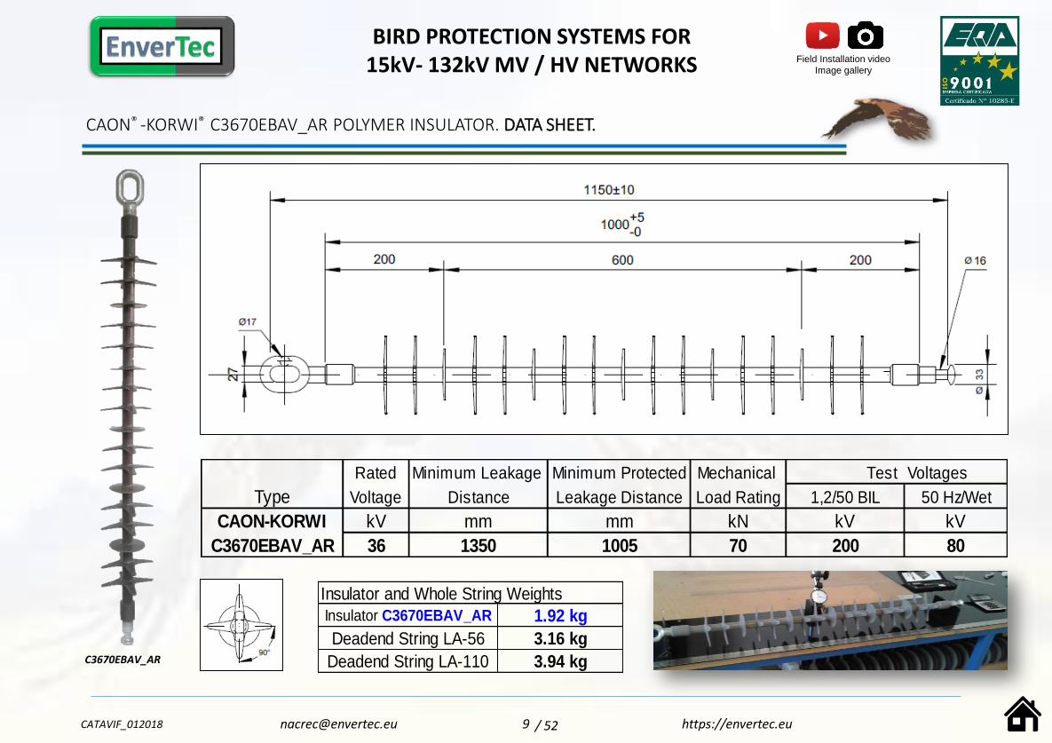
CAON® -KORWI® C3670EBAV_AR POLYMER INSULATOR. DATA SHEET.
Rated Minimum Leakage Minimum Protected Mechanical Test Voltages
Type Voltage Distance Leakage Distance Load Rating 1,2/50 BIL 50 Hz/Wet
CAON-KORWI kV mm mm kN kV kV
C3670EBAV_AR 36 1350 1005 70 200 80
Insulator and Whole String Weights
Insulator C3670EBAV_AR 1.92 kg
Deadend String LA-56 3.16 kg
Deadend String LA-110 3.94 kgC3670EBAV_AR
BIRD PROTECTION SYSTEMS FOR 15kV- 132kV MV / HV NETWORKS
CATAVIF_012018 9 https://[email protected]
Field Installation video
Image gallery
/ 52

MATERIALS , FEATURES AND VALUE ADDED. PROVEN PERFORMANCE.
C3670EBAV_AR
INSULATING CORE: Fibreglass reinforced Epoxy resin – Acid resistant – High Mechanical Stress resistance (70kN).
• HTV SILICONE CONTINUOUS ENVELOPE WITH Hc2 HYDROPHOBICITY LEVEL: Owing to its composition and nature it repels the build-up of
moisture. This insulator has a minimum silicone thickness of 4.5mm , ensuring excellent performance in highly polluted areas.
• METAL FITTINGS: The Zinc (Zn) coating thickness on the fittings –Ring/Ball- has been reinforced to 120 μm, in accordance with the EN 60383-1
standard.
• DESIGN 100% by EnverTec S.L. (Granada – Spain).
• Detailed specification of each manufacturing batch.
• Monitoring of the insulator manufacturing process. Traceability Assurance.
• Extended quality control:
•Testing at independent accredited laboratory of the polymer envelope material used for each batch.
• Individual and sampling tests as per UNE-EN 61109:2010 and the criteria set out in the ISO 17025 Standard.
•QUALITY AND TRACEABILITY ASSESSMENT report for each batch of insulators supplied.
BIRD PROTECTION SYSTEMS FOR 15kV- 132kV MV / HV NETWORKS
CATAVIF_012018 10
COMPONENTS AND MATERIALS
VALUE ADDED THROUGH
https://[email protected]
> 5,500 pcsinstalled2015 - 2017
Field Installation video
Image gallery
/ 52
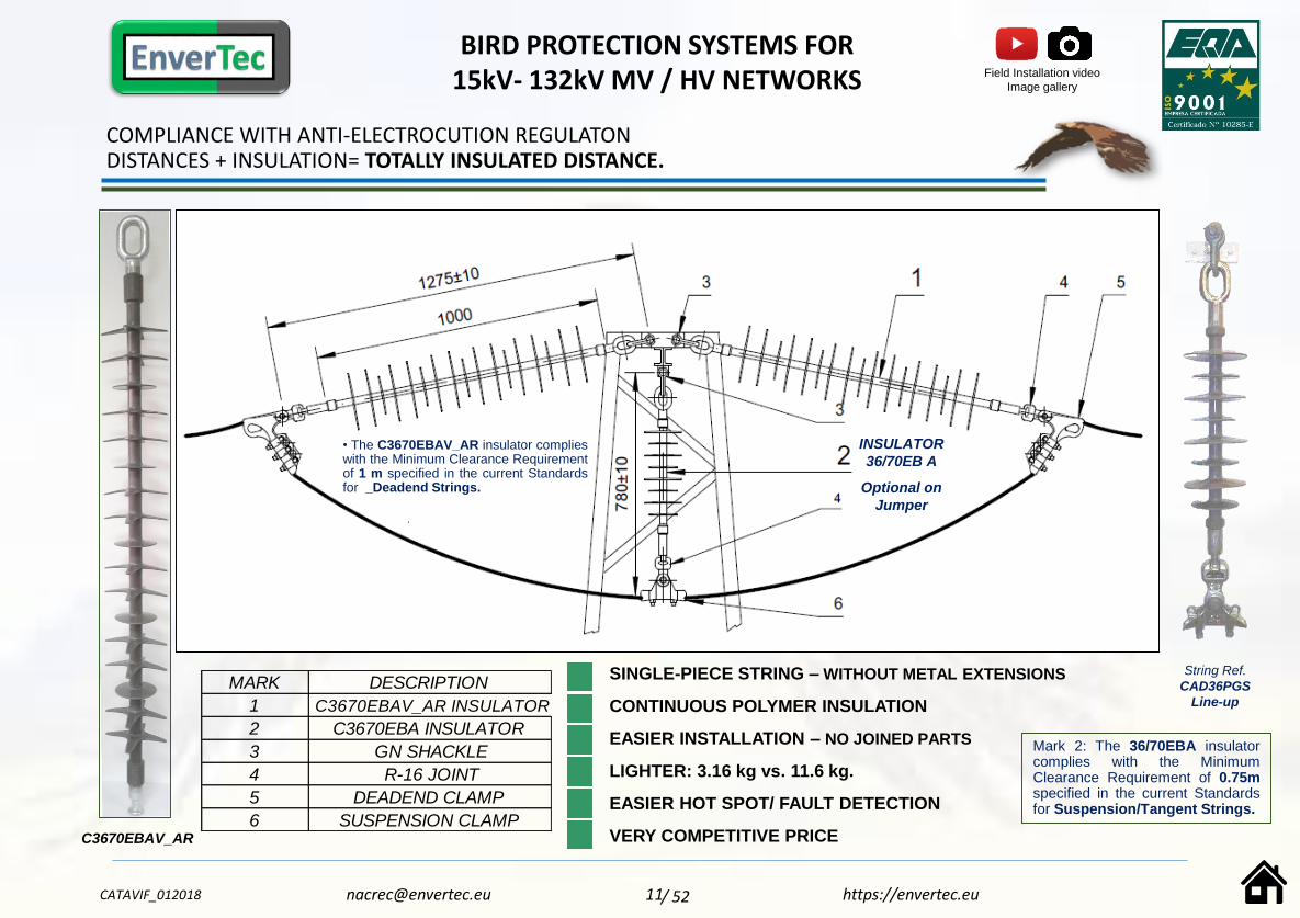
COMPLIANCE WITH ANTI-ELECTROCUTION REGULATONDISTANCES + INSULATION= TOTALLY INSULATED DISTANCE.
MARK DESCRIPTION
1 C3670EBAV_AR INSULATOR
2 C3670EBA INSULATOR
3 GN SHACKLE
4 R-16 JOINT
5 DEADEND CLAMP
6 SUSPENSION CLAMP
SINGLE-PIECE STRING – WITHOUT METAL EXTENSIONS
CONTINUOUS POLYMER INSULATION
EASIER INSTALLATION – NO JOINED PARTS
LIGHTER: 3.16 kg vs. 11.6 kg.
EASIER HOT SPOT/ FAULT DETECTION
VERY COMPETITIVE PRICE
• The C3670EBAV_AR insulator complieswith the Minimum Clearance Requirementof 1 m specified in the current Standardsfor _Deadend Strings.
INSULATOR
36/70EB A
Optional on
Jumper
C3670EBAV_AR
String Ref.
CAD36PGS
Line-up
Mark 2: The 36/70EBA insulatorcomplies with the MinimumClearance Requirement of 0.75mspecified in the current Standardsfor Suspension/Tangent Strings.
BIRD PROTECTION SYSTEMS FOR 15kV- 132kV MV / HV NETWORKS
CATAVIF_012018 11 https://[email protected]
Field Installation video
Image gallery
/ 52

24-36kV SUSPENSION-TANGENT INSULATOR STRINGS . CLEARANCE >750mm.
CAD36PGS SUSPENSION STRING – WITH MODEL 36/70EB A INSULATOR- 36 kV 70kN -
ENDESA STANDARD GE-AND012 / Endesa Code 6702343 – TAM 300032
• The CAD36PGS insulator string provides a clearance in excess of 0.75 m between the conductor
and the crossarm shackle, thereby assuring compliance with the requirements of the current
Standard requirements for Line-up Strings.
Complete String. CAD36PGS Line-up
Rated Minimum Leakage Min. Protected Mechanical Test Voltages
Type Voltage Distance Leakage Dist. Load 1,2/50 BIL 50 Hz/Wet
kV mm mm kN kV kV
C3670 EB A 36 980 415 70 170 70
MODEL 36/70EB INSULATOR
BIRD PROTECTION SYSTEMS FOR 15kV- 132kV MV / HV NETWORKS
CATAVIF_012018 12 https://[email protected]
Field Installation video
Image gallery
/ 52

CAON® -KORWI® C3670EBAV_AR POLYMER INSULATOR. IMAGE GALLERY 2013 - 2017.
Installation Platform Prototype
BIRD PROTECTION SYSTEMS FOR 15kV- 132kV MV / HV NETWORKS
CATAVIF_012018 13 https://[email protected]
> 5,500 pcsInstalled2015 - 2017
/ 52

CAON®-KORWI® POLYMER PHASE SPACERS _ Models DP – DPS .
INNOVATIVE SOLUTIONS FOR EXISTING LINES _ 15 - 132kV
Lengths ≤ 3,000mm – Conductor size range Ø6 – Ø28mm
BIRD-PROTECTION AND POWER SUPPLY CONTINUITY SYSTEMS FOR 15kV – 132kV
MV / HV NETWORKS
PO
LYM
ERP
HA
SESPA
CER
S
CATAVIF_012018 14
EXCLUSIVE LIVE INSTALLATION SYSTEM USING HOTSTICKS
https://[email protected]
- Patent Pending
Field Installation video
Image gallery
/ 52
ModeLDPS
≥45kV
≤132kV
© ENVERTEC S.L.
05/2017
ModeL DP
≥15kV
≤45kV
© ENVERTEC S.L.
05/2017© ENVERTEC S.L.
05/2017
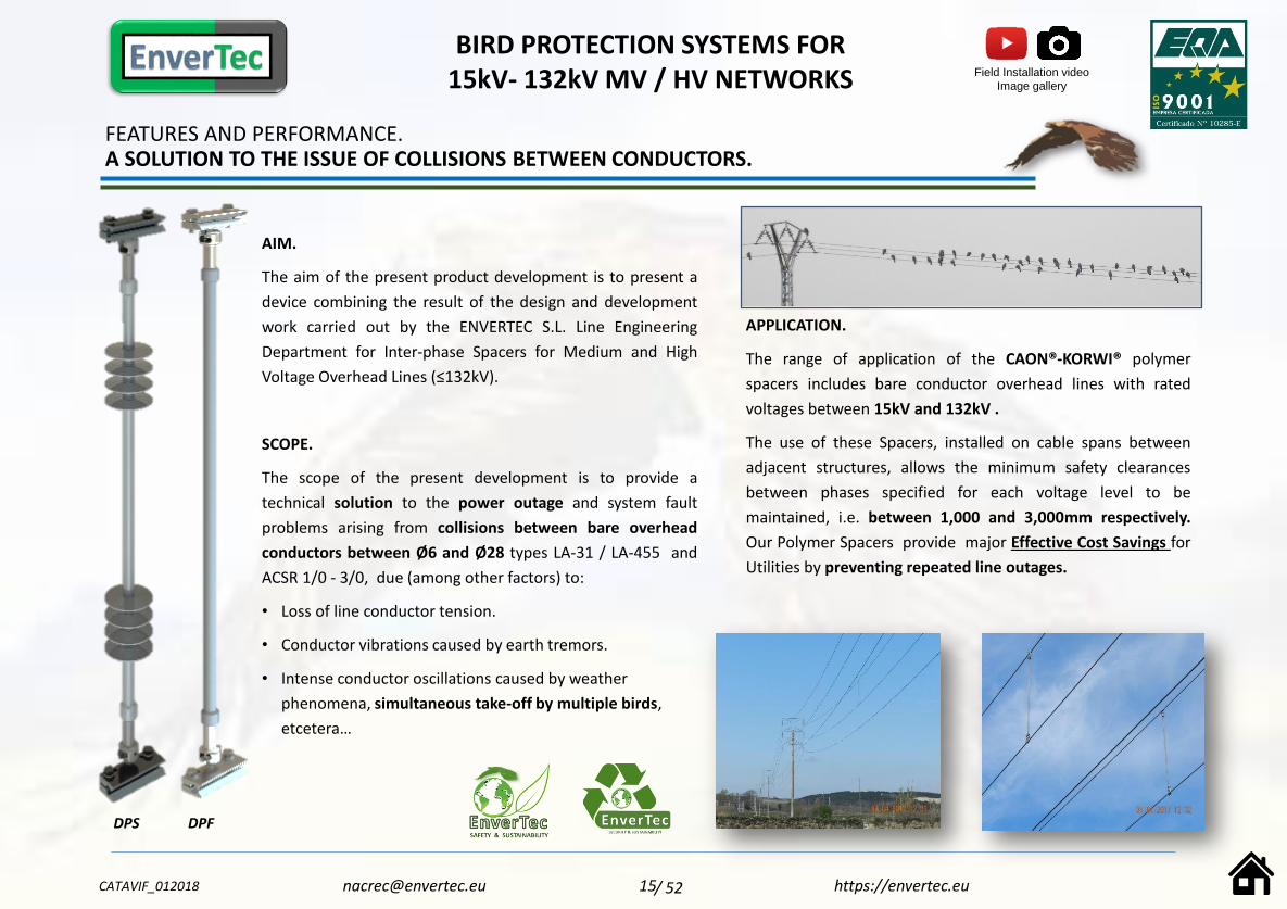
FEATURES AND PERFORMANCE. A SOLUTION TO THE ISSUE OF COLLISIONS BETWEEN CONDUCTORS.
AIM.
The aim of the present product development is to present a
device combining the result of the design and development
work carried out by the ENVERTEC S.L. Line Engineering
Department for Inter-phase Spacers for Medium and High
Voltage Overhead Lines (≤132kV).
SCOPE.
The scope of the present development is to provide a
technical solution to the power outage and system fault
problems arising from collisions between bare overhead
conductors between Ø6 and Ø28 types LA-31 / LA-455 and
ACSR 1/0 - 3/0, due (among other factors) to:
• Loss of line conductor tension.
• Conductor vibrations caused by earth tremors.
• Intense conductor oscillations caused by weather
phenomena, simultaneous take-off by multiple birds,
etcetera…
DPS DPF
BIRD PROTECTION SYSTEMS FOR 15kV- 132kV MV / HV NETWORKS
CATAVIF_012018 15 https://[email protected]
APPLICATION.
The range of application of the CAON®-KORWI® polymer
spacers includes bare conductor overhead lines with rated
voltages between 15kV and 132kV .
The use of these Spacers, installed on cable spans between
adjacent structures, allows the minimum safety clearances
between phases specified for each voltage level to be
maintained, i.e. between 1,000 and 3,000mm respectively.
Our Polymer Spacers provide major Effective Cost Savings for
Utilities by preventing repeated line outages.
Field Installation video
Image gallery
/ 52

MOST RELEVANT DESIGN FEATURES
• INSTALLATION IN ENERGISED CONDITION USING HOTSTICKS.
• Our specific clamp, by means of an exclusive system, stays open
until it is installed and secured onto the conductor using
insulated hotsticks. The coupling system between the Fixing
Clamp and the Spacer fittings is based on the Ball and Socket
system, in accordance with the IEC60120-11(B) Standard. This
system allows simple installation and/or easy replacement of the
Spacer Fixing Clamp.
• The articulation allowed by this coupling system is limited to 5° in
all directions, which is ideal for attenuating the effects on the
Spacer of sudden, whiplash type movements, and other
oscillations experienced by conductors due to several causes:
Weather conditions: wind, storms…
Loss of line conductor tension and earth tremors.
Simultaneous take-off by multiple birds.
• The main purpose of the Spacers is to maintain a minimum
safety clearance between phases, therefore the rated tensile
stress of between 45kN and 70kN is enough to fulfil their
intended purpose, and adhere to one of the basic precepts of
design: devices with the lightest possible weight. This aspect
becomes more important as the diameter of the conductor on
which they are installed decreases.
FEATURES AND PERFORMANCE. PREVENTING POWER OUTAGES.
BIRD PROTECTION SYSTEMS FOR 15kV- 132kV MV / HV NETWORKS
Installations in northern Spain – July_ 45kV line. Total phase-phase distance 1,400mm.
CATAVIF_012018 16 https://[email protected]
DPS DPF
Patent Pending
Installation, - on energisedlines using hotsticks - ,
fitted onto conductor bymeans of insulated hotsticks
with universal toolaccessories.
> Request further information, drawings and data sheets.
Field Installation video
Image gallery
/ 52

CAON-KORWI ® Phase spacers
Length range 1,000 – 3,000mm _ Rated Voltage 15kV- 132kV.
IMAGE GALLERY – MV LINE ENDESA / ENEL -ELECTRICAL SYSTEM PROTECTION _
OUTAGE PREVENTION AND BIRD PRESERVATION.
DP TYPE POLYMER SPACERS
AIM OF PROCEDURE:
Prevent electrocution of
local bird species by maintaining
minimum phase-phase distances, on MV overhead
lines experiencing incidents due to massive bird
presence and their simultaneous take-
off, thereby assuring continuous
power supply.
LOCATION:
Mancha Real (Jaén-Spain).
La Pagoda – Arroyo Vil Altitude 770m above sea level.
INSTALLATION CONDITIONS:
LIVE LINE WORK_ ENERGISED LINE
CONDUCTOR: LA-56 (54.6mm2) – Vr. 20kV.
DATE AND TIME:
06/09/2017_10h/12h.
WEATHER CONDITIONS:
DRY AND SUNNY
+20ºC.
Acknowledgements:
ENDESA DAOR JAEN
JUAN GALINDO S.L..
2
3
4
5
1.- Retrofitting 2,40m. Herringbone line with loss of conductor tension.
2.- Locating DP Spacer at lowest point in mid span.
3.- Measuring spacing distance required.
4.- Trimming the spacer to the required length.
5.- Attaching the DP spacer by means of specific ties.
ACTUAL INSTALLATION TIME: 15 minutes.
https://envertec.eu
+ info: [email protected]
1
CATAVIF_012018
17 / 52

RETROFITTING OF EXISTING LINES WITH DEVICES OF PROVEN EFFECTIVENESS.
COMPLIANT WITH CURRENT BIRD ELECTROCUTION REGULATIONS
CAON®-KORWI® SILICONE COVERS FOR USE ON MEDIUM VOLTAGE OVERHEADDISTRIBUTION LINES. 15 – 45kV.
BIRD PROTECTION SYSTEMS FOR 15kV – 45kV MV / HV NETWORKS.
SILICO
NE
DEV
ICES
SWP
STSC
SPSC
SPGSA
SPP
SPPL
SPAV
SAP
SPSA
SPEB
P R O T E C T I V E C O V E RF O R C O N D U C T O R S
P R O T E C T I V E C O V E RF O R D E A D E N D C L A M P S
P R O T E C T I V E C O V E RF O R S U S P E N S I O N C L A M P S
P R O T E C T I V E C O V E RF O R R E I N F O R C E D
S U S P E N S I O N C L A M P S 4 5 k V
P R O T E C T I V E C O V E R F O RT R A N S F O R M E R B U S H I N G S
P R O T E C T I V E C O V E R F O RP I N - T Y P E P O L I M E R
I N S U L A T O R W I T H 2 O U T L E T S .
P R O T E C T I V E C O V E R F O RG L A S S P I N - T Y P E I N S U L AT O R
A R V I S T Y L E
P R O T E C T I V E C O V E RF O R S U R G E A R R E S T E R S
P R O T E C T I V E C O V E RF O R C A B L E T E R M I N AT I O N S
P R O T E C T I V E C O V E RF O R A M PA C T / G R I M P I
S P L I C E S
pg
20
pg
21
pg
23
pg
25
pg
26
pg
28
pg
29
pg
30
pg
31
pg
32
CATAVIF_012018 18 https://[email protected]
Specific solutions for Protecting Electrical Systems and ensuring a Continuous Power Supply
/ 52
pg
19

HIGH PERFORMANCE MATERIALS _ APPLIED R&D&I FOR RESPONSIBLE INSTALLATIONS.
INTRODUCTION.
The CAON®-KORWI® Silicone Covers have been developed as a protective measure against bird electrocutionon overhead distribution power lines up to 36kV.
These devices are designed for retrofitting on existing lines where the installation of our model C3670EBAV orC3670EBAV_AR. Bird-Protection Insulators is not feasible.
The purpose of these devices is to offer protection to bird species from electrocution due either to
simultaneous contact by the bird with a conductor and the structure, or simultaneous contact with two phases.
These devices are also effective in protecting overhead lines from other short-circuit causes, such as tree
branches, vandalism, etc., thereby preventing fire hazards and power outages.
NOMINAL MATERIAL CHARACTERISTICS COMMON TO ALL COVERS
MANUFACTURED WITH >> SPECIFIC ADVANCED FORMULATION SILICONE WITH A HYDROPHOBICITY LEVEL
of Hc2. Due to their composition and nature they repel the build-up of moisture and are permeable to
Oxygen. These devices have a minimum silicone thickness of 3 to 3.5mm (depending on the model), ensuring
excellent performance under exposure to UV radiation , with no colour degradation or crystallisation, and
they are effective even in areas with extremely high saline pollution. Thanks to their advanced technology,
our covers show Lower Leakage Currents, thanks to the hydrophobic properties they transmit to the
contaminant layer.
• GUARANTEE: Our Silicone is Ozone Resistant (UNE EN 60811-403) and thanks to its advanced formulation itcan improve its dielectric strength after passing the 1000h Weathering Test – UNE EN 60243-1. In addition,the 5 000h Weathering Tests , -IEC 6119 Annex C- , performed at the STRI (Sweden) Laboratory - whichinclude the harmful effects of Saline Fog - allow us to estimate the service life of our covers at a minimum of20 years.
• ENVIRONMENT FRIENDLY AND SUSTAINABLE: The material used to manufacture the covers is a safe inert
material,, containing no microbial agents and giving off no contaminants to the surrounding environment. It
can be easily recycled at the nearest waste collection point. The packaging is made with recycled carton sealed
with organic paper adhesive tape.
Test Laboratories CAON Ltd. & ENVERTEC S.L.
SWEDEN MEXICO
SPAIN
BIRD PROTECTION SYSTEMS FOR 15kV – 45kV MV / HV NETWORKS
NOMINAL MATERIAL CHARACTERISTICS
NameSilicone Rubber (White carbon
black)
TypeHTV. High temperature
vulcanised (180°) siliconerubber component
Model110-2 (60W molecular film at
65W)
Hydrophobic coatingWater permeability level Hc2 –
WC2
MECHANICAL CHARACTERISTICS
Flammability 650ºC (UNE 60695-2-11)
Density >1,1 g/cm 3 (ISO-868)
Strength >50 Shore A (ISO-868)
Tensile Strength >4N/mm 2 (EN 60811-501)
Elasticity Modulus >200% (EN 60811-501)
Tear Resistance >10N/mm 2 (UNE-HD-605)
Dielectric Strength >18kV/mm (UNE 60243-1)
Ozone Resistance 250ppm (UNE 60811-403:2012)
CATAVIF_012018 19 https://[email protected] / 52

PROTECTIVE CONDUCTOR COVER. SWP FAMILYModels SWP-12_SWP-16 _SWP-22 – TAM 30100/30013/300012.
Models:
Conductor covers are available in three different reference numbers with internal diameters of 12,16, and 22 mm respectively, to cover the range of conductors from LA-31 to LA-280/HAWK.
Installation:
Installation of the SWP covers is carried out by hand, requiring no tools, following a simpleprocedure, thanks to the properties of the silicone material they are made of.
The tongue and groove locking design allows a quick, but secure and enduring installation,.
Fitting of the cover is performed by means of AISI-316 STAINLESS STEEL ties, or alternatively usingSelf-vulcanising Silicone tape, depending on the criteria followed by the local utility. To ensureproper locking of the cover on long sections, self-vulcanising silicone tape must be applied atregular intervals and on the end points.
Advantages:
• The properties and flexibility of the cover’s silicone material makes it very easy to work with,easily adapting to the installation requirements of each specific application, including small radiuscurves (Fig A-B). Another advantage is that it allows fast and easy trimming to the required length.
• The shape and size of the SWP hose, considerably smaller than other models on the market,ensures better performance under wind conditions (the “snaking” effect causes slipping along thespan when the cover detaches from its fixing point), and an exceptional response to the effectscaused by snow and ice, thanks to its hydrophobic properties.
Standard Format and Packaging:
The SWP conductor cover is supplied in 20 m long coils in RAL 3031 colour, packed in recyclablecardboard boxes.
Each package is clearly marked with the cover model it contains, as well as information on themonth/year of manufacture, Batch No, and handling and storage instructions. It includes a QRCode providing access to the field installation video.
Inside the carton is a detailed Instruction Manual, in A4 size, double-side printed in colour, forproper installation of the cover and its fixing and lock securing accessories.
G Ø D
AISI-316 Stainless Steel Ties4.6x0.25x200mm MOCAP X-TREME
Self-VulcanisingSilicone Tape
Standard format: 20m coils packed in cartons
Ref. D G Format Protection
Model (mm) (mm) Coils / m Range (kV)
SWP-12 12 +1/-0 3 +0,1/-0 20 36
SWP-16 16 +1/-0 3 +0,1/-0 20 36
SWP-22 22 + 1/-0 3,5+0,1/-0 20 36
Fig. A: Effectiveness of SWP Device to cover small radius
curves.
BIRD PROTECTION SYSTEMS FOR 15kV – 36kV MV / HV NETWORKS
CATAVIF_012018 20 https://[email protected]
Field Installation video Image gallery
> 100,000m Installed2014 - 2017
Fig. B
/ 52

DEADEND CLAMP COVER. MODEL STSCUSE ON GA-1 / GA-2 DEADEND CLAMPS TAM 300100.
Design Features:
The STSC protective cover is designed to cover the GA-1 and GA-2 type ball joints and deadend clampsfor a conductor size range of 6 to 16mm diameter, on distribution lines up to 36kV.
With a silicone thickness of 3.5 mm, this device has the required and adequate dielectric strength to
ensure satisfactory performance throughout its entire service life.
Installation:
Its clamshell opening design, with 11 locking points by means of pins, (preinstalled on each device),
allows easy installation by hand with no tools on existing lines. (Figs. 1 & 2 ).
Advantages: Its design includes features to prevent moisture condensation and rainwater ingress; in
addition to the lower rectangular opening, its design includes two sections, a cylinder-shaped and a
cone-shaped one, which, by means of silicone tape or UV resistant plastic ties and thanks to the
inherent properties of the silicone material, allow fitting over the metal ball joint of the insulator on
one side and the conductor cover on the other, performing a twofold function: on the one hand
hindering water ingress and on the other providing an additional fixing for the SWP conductor cover,
securing it to prevent it from slipping along the conductor. The inherent flexibility and nature of the
material allows the device to be easily adapted to the specific needs of each application and to trim off
excess portions (cylindrical section) depending on the type of insulator installed on the line: Polymer
(Figs. 3-4), or Glass( Fig. 5). For the latter, the cover’s “hinge-less” design allows perfect insulation of
the metal ball joint, as the glass insulator is “flush” against the STSC device.
Standard Format and Packaging:
Model STSC covers are supplied in recyclable cartons holding 6 RAL 3031 red units each.
Each package includes information on the month and year of manufacture, Batch No, as well as handling, storage and recycling instructions. Inside the carton is a detailedInstruction Manual, for proper installation of the cover. Includes a QR Code providing access to the field installation video.
1
2
Installation on Polymer Insulators. Sealing of cone-shaped section and cylinder-shaped
section.Installation on U-40, U-70 , U-100 glassinsulators. Sealling of cone-shaped section.
BIRD PROTECTION SYSTEMS FOR 15kV – 36kV MV / HV NETWORKS
CATAVIF_012018 21 https://[email protected]
Field Installation video
Image gallery
> 30,000 pcmInstallled2014 - 2017
3
5
4
2
/ 52

Design Features:
The STSC13 protective cover is designed to cover the metal ball joint and GA-3 type deadendclamps. (Figs. 1 &2 ). Its design also allows its use to cover Compression Clamps, on a conductorsize range up to LA-180, on distribution lines from 15 to 36kV. (Fig. 3).
With a silicone thickness of 3.5 mm, this device has the required and adequate dielectric strength to
ensure satisfactory performance throughout its entire service life.
Installation:
Its clamshell opening design, with 13 locking points by means of pins, (preinstalled on each device),
allows easy installation by hand with no tools on existing lines. (Fig. 1).
Advantages: Its design includes features to prevent moisture condensation and rainwater ingress;
in addition to the lower rectangular opening, its design includes two sections, a cylinder-shaped
and a cone-shaped one, which, by means of silicone tape or UV resistant plastic ties and thanks to
the inherent properties of the silicone material, allow fitting over the metal ball joint of the
insulator on one side and the conductor cover on the other, performing a twofold function: on the
one hand hindering water ingress and on the other providing an additional fixing for the SWP
conductor cover, securing it to prevent it from slipping along the conductor.
The inherent flexibility and nature of the material allows the device to be easily adapted to the
specific needs of each application and to trim excess portions (cylinder-shaped section) depending
on the type of insulator installed on the line: Polymer (Figs. 5a-5b), or Glass (Figs. 4a-4b). For the
latter, the cover’s design allows perfect insulation of the metal ball joint, as the glass insulator is
“flush” against the STSC13 device.
Standard Format and Packaging:
Model STSC13 clamp covers are supplied in recyclable cartons holding 2 RAL 3031 red units each.
Each package includes information on the month and year of manufacture, Batch No, as well as handling, storage and recycling instructions. Inside the carton is a detailedInstruction Manual, for proper installation of the cover. Includes a QR Code providing access to the field installation video.
BIRD PROTECTION SYSTEMS FOR 15kV – 36kV MV / HV NETWORKS
CATAVIF_012018 22 https://[email protected]
DEADEND CLAMP COVER. MODEL STSC13USE ON GA-3 DEADEND CLAMPS and COMPRESSION CLAMPS. TAM 300023.
Installation on Polymer Insulators.
Sealing of cone-shaped section and
cylinder-shaped section.
Installation on U-70, U100,U-120 glass
insulators. Sealing of cone-shaped section.
1
5b 5a
2
Representation
of installation on
Compression
Clamps up to
L-180.
3
4b 4a5
4
/ 52

SUSPENSION CLAMP COVER MODEL SPSC
Installation on Polymer Insulatorsand sealing of upper cone.
4
6
1
Installation on U-40 GlassInsulators (Fig. 6) , and U-70,
U-100 , U-120 (Fig.7).
4
BIRD PROTECTION SYSTEMS FOR 15kV – 36kV MV / HV NETWORKS
Design Features:
The SPSC protective cover is designed to effectively cover the GS-1 and GS-2 type ball joints and
suspension clamps for a conductor size range of 5 to 17 mm diameter, on distribution lines up to
36kV. (Fig.2)
The silicone thickness used is 3.5 mm, conferring the device the necessary dielectric strength
and ensuring its enduring effective performance.
Installation:
Its clamshell opening design, with 6 locking points by means of pins, (preinstalled on each
device), allows easy installation by hand with no tools on existing lines.
Two water draining holes with a 12° depression have been incorporated to minimise potential
water ingress. (Fig. 1) .
Advantages:
The design features to avoid moisture condensation and prevent rainwater ingress caused by the
vertical installation of these clamp covers are reinforced by the cone-shaped design of the top
part of the device (Fig.1 ), which can be sealed, depending on the type of insulator present on
the line, using silicone tape. The inherent properties of the material allow the device to be
easily adapted to the specific needs of each application, covering up all the metal parts and
allowing easy trimming of excess portions of this cone when performing its installation on some
of the existing insulator types: Polymer (Figs. 3 & 4) , or Glass (Figs. 5 & 6).
Standard Format and Packaging:
Model SPSC clamp covers are supplied in recyclable cartons holding 6 RAL 3031 red units each.
Each package includes information on the month and year of manufacture, Batch No, as well as handling, storage and recycling instructions. Inside the carton is a detailedInstruction Manual, for proper installation of the cover. Includes a QR Code providing access to the field installation video.
2
3
CATAVIF_012018 23 https://[email protected]
> 6,500 pcsinstalled2014 - 2017
Field Installation video
Image gallery
/ 52
3
5

Design Features:
The SPSC13 protective cover is designed to effectively cover the GS-3 and GS-4 type ball joints and
deadend clamps for a conductor size range of up to 28 mm, on distribution lines up to 36kV.
The silicone thickness used is 3.5 mm, conferring the device the necessary dielectric strength and
ensuring its enduring effective performance .
Installation:
Its clamshell opening design, with 14 locking points by means of pins, (preinstalled on each device),
allows easy installation by hand with no tools on existing lines.
Two water draining holes with an angular depression have been incorporated to minimise potential
water ingress. (Fig. 1) .
Ventajas: The design features to avoid moisture condensation and prevent rainwater ingress
caused by the vertical installation of these clamp covers are reinforced by the cone-shaped design
of the top part of the device (Fig.2 ), which can be sealed, depending on the type of insulator
present on the line, using silicone tape. The inherent properties of the material allow the device to
be easily adapted to the specific needs of each application, covering up all the metal parts and
allowing easy trimming of excess portions of this cone when performing its installation on some of
the existing insulator types: Polymer (Figs. 3 & 4), or Glass (Figs. 5 & 6).
The design and dimensions of the SPSC13 protective cover allow its installation on glass insulators
with either long or short ball joints; the length of the section required to be trimmed off is specified
in the Manual.
Standard Format and Packaging:Model SPSC13 clamp covers are supplied in recyclable cartons holding 3 RAL 3031 red units each.
Each package includes information on the month and year of manufacture, Batch No, as well as handling, storage and recycling instructions. Inside the carton is a detailedInstruction Manual , for proper installation of the cover. Includes a QR Code providing access to the field installation video.
Installation on PolymerInsulators
Adjustment for Installation onU-70 , U-100 , and U-120 (Fig.5-6) Glass Insulators.
21
3 4
5 6
BIRD PROTECTION SYSTEMS FOR 15kV – 36kV MV / HV NETWORKS
CATAVIF_012018 24 https://[email protected]
SUSPENSION CLAMP COVER. MODEL SPSC13USE ON GS-3 / GS-4 SUSPENSION CLAMPS. TAM 300025.
/ 52

SILICONE COVER FOR GS-4 / GSA-4 SUSPENSION CLAMPSCONDUCTOR SIZE RANGE UP TO CONDOR / Ø28mm . Vr 45kV / Vc 25.98kV.
1,370mm
215mm
128mm
21
0m
m
BIRD PROTECTION SYSTEMS FOR 15kV – 45kV MV / HV NETWORKS
CATAVIF_012018 25 https://[email protected] / 52
COVER SUITABLE FOR HOUSING REGULAR and REINFORCED SUSPENSION CLAMPS
COVER FOR POLYMER POST INSULATORS. MODEL SPPCOVER FOR POLYMER SUPPORT INSULATORS AND TRANSFORMER BUSHINGS.
Design Features:
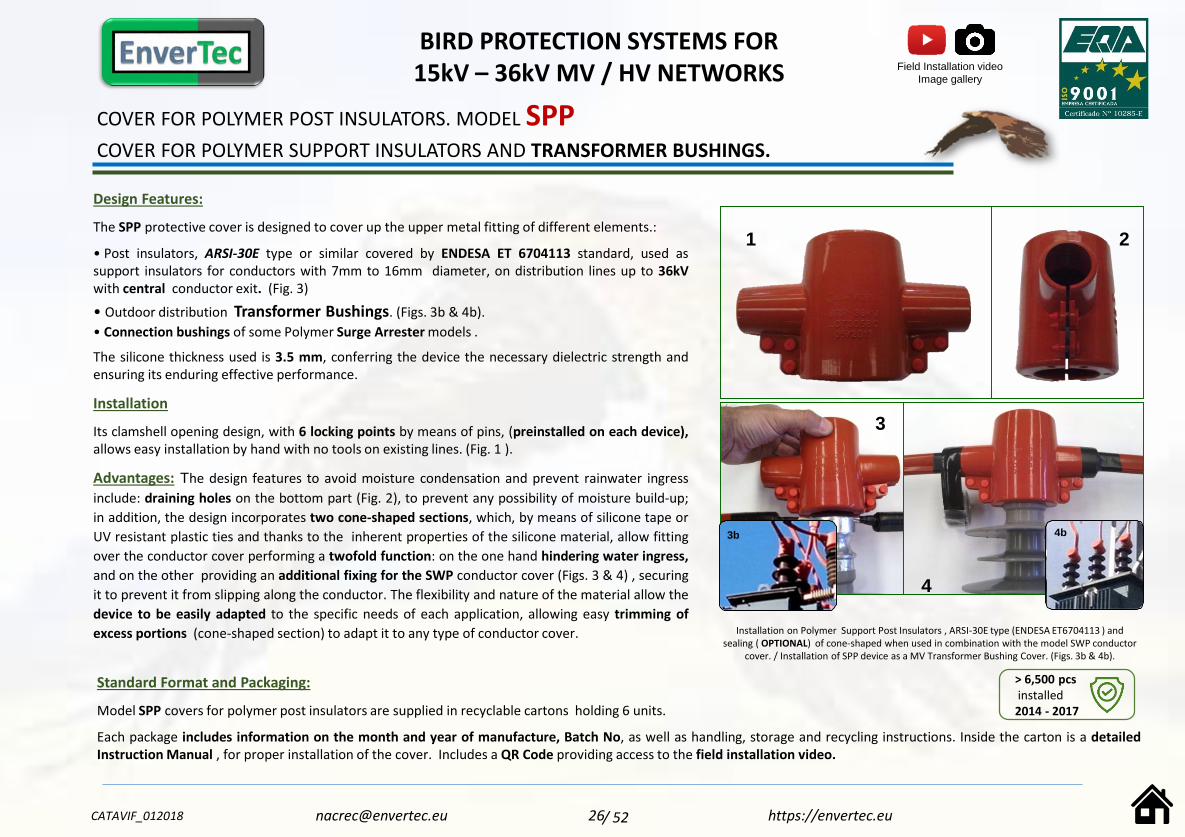
The SPP protective cover is designed to cover up the upper metal fitting of different elements.:
• Post insulators, ARSI-30E type or similar covered by ENDESA ET 6704113 standard, used assupport insulators for conductors with 7mm to 16mm diameter, on distribution lines up to 36kVwith central conductor exit. (Fig. 3)
• Outdoor distribution Transformer Bushings. (Figs. 3b & 4b).
• Connection bushings of some Polymer Surge Arrester models .
The silicone thickness used is 3.5 mm, conferring the device the necessary dielectric strength andensuring its enduring effective performance.
Installation
Its clamshell opening design, with 6 locking points by means of pins, (preinstalled on each device),allows easy installation by hand with no tools on existing lines. (Fig. 1 ).
Advantages: The design features to avoid moisture condensation and prevent rainwater ingress
include: draining holes on the bottom part (Fig. 2), to prevent any possibility of moisture build-up;
in addition, the design incorporates two cone-shaped sections, which, by means of silicone tape or
UV resistant plastic ties and thanks to the inherent properties of the silicone material, allow fitting
over the conductor cover performing a twofold function: on the one hand hindering water ingress,
and on the other providing an additional fixing for the SWP conductor cover (Figs. 3 & 4) , securing
it to prevent it from slipping along the conductor. The flexibility and nature of the material allow the
device to be easily adapted to the specific needs of each application, allowing easy trimming of
excess portions (cone-shaped section) to adapt it to any type of conductor cover.
Standard Format and Packaging:
Model SPP covers for polymer post insulators are supplied in recyclable cartons holding 6 units.
Each package includes information on the month and year of manufacture, Batch No, as well as handling, storage and recycling instructions. Inside the carton is a detailedInstruction Manual , for proper installation of the cover. Includes a QR Code providing access to the field installation video.
2
Installation on Polymer Support Post Insulators , ARSI-30E type (ENDESA ET6704113 ) and sealing ( OPTIONAL) of cone-shaped when used in combination with the model SWP conductor
cover. / Installation of SPP device as a MV Transformer Bushing Cover. (Figs. 3b & 4b).
1
3
4
4b
BIRD PROTECTION SYSTEMS FOR 15kV – 36kV MV / HV NETWORKS
CATAVIF_012018 26 https://[email protected]
Field Installation video
Image gallery
/ 52
3b
> 6,500 pcsinstalled2014 - 2017

COVER FOR COMBINATION OF PD TYPE POST INSULATOR + ACSR CONDUCTOR 1/0_3/0_336
COVER FOR USE ON MV LINE POST INSULATORS. MODEL SPPMX336
Design Features: The SPPMX336 cover has been specifically designed to address the bird
electrocution issues and constant outages on the MV overhead lines (13<34.5kV) of the C.F.E.
power grid in Mexico. These covers are suitable for simultaneously covering up the PD type post
insulators and the ACSR type conductor. The main feature of the SPPMX336 cover is that it is a
one-piece device (Fig.1) consisting of:
· A cylinder-shaped middle section whose purpose is to cover a ceramic (Fig.2) or polymer (Fig. 1)insulator with sheds up to 120mm in diameter, intended to cover up both the top of the insulatorand the tied conductor section.
· Two cylindrical sections with tapered fitting ends on either side (Fig.4), intended to cover up atotal length of 1,050mm . The cylinder has an inner capacity of 39mm , allowing it to insulate theACSR 1/0_3/0_336 conductor range, together with its metal ties. The silicone thickness used is 3.5mm, conferring the device the necessary dielectric strength and ensuring its enduring effectiveperformance.
Installation: Its clamshell opening design, with 14 locking points by means of pins, (preinstalled
on each device), allows easy installation by hand with no tools on existing lines. (Fig. 3 ).
Advantages: Design features have been incorporated to avoid moisture condensation and for
draining rainwater, providing the device with a non-watertight longitudinal locking system.
• The tapered top part of the central cylinder-shaped body (Fig.1 a), prevents water build-up and
protects the insulator from the harmful effects of bird droppings.
• The tapered sections on either end (Fig.4), fit tightly onto the conductor, keeping it free from
contamination, dirt and potential nesting.
Standard Format and Packaging:Model SPPMX336 covers for rigid polymer insulators are supplied in recyclable cartons holding 3 or 6 RAL 3031 red units.
Each package includes information on the month and year of manufacture, Batch No, as well as handling, storage and recycling instructions. Inside the carton is a detailedInstruction Manual , for proper installation of the cover. Includes a QR Code providing access to the field installation video.
The inherent flexibility and properties of the materialallow the device to be easily installed and adapted tothe specific needs of each individual application. Thetapered ends on either side can be adapted to theconductor diameter, only leaving the recommendedgap for proper water drainage.
1
2
3
4
1a
BIRD PROTECTION SYSTEMS FOR 15kV – 36kV MV / HV NETWORKS
CATAVIF_012018 27 https://[email protected]
ImageGallery
/ 52

COVER FOR POLYMER POST INSULATORS.
CONDUCTOR CENTRAL AND SIDE EXIT. MODEL SPPL
Design Features:
The SPPL protective cover is designed to cover the upper metal fitting of different elements:
•ARSI-30E type or similar post insulators covered by ENDESA Standard ET 6704113, used assupport insulators for conductors between 7mm and 16mm in diameter, on distribution lines up to36kV with conductor central or side exit.
• Outdoor distribution Transformer Bushings.
• Connection bushings of some Polymer Surge Arrester models.
The silicone thickness used is 3.5 mm, conferring the device the necessary dielectric strength andensuring its enduring effective performance.
Installation:
Once the conductor (A) has been covered up with a suitable protective cover for the conductordiameter, this is fitted to ensure the conductor is protected as close as possible to the neck of theinsulator. Then open the SPPL device and fit it over the insulator’s metal neck, so as to cover it upcompletely, and secure it by means of the 4 preinstalled pins provided. The images show our Mod.SWP silicone conductor cover (B), secured by means of self-welding silicone tape Mod. X-TREME®(C) .
Advantages:
The design features to avoid moisture condensation and prevent rainwater ingress include: draining
holes on the bottom part (Fig. 2), to prevent any possibility of moisture build-up. The inherent
properties and flexibility of the material allow the device to be easily adapted to the specific needs
of each individual application, and trimming of excess portions, to allow fitting it to any type of
conductor cover.
Standard Format and Packaging:
Model SPPL covers for polymer post insulators are supplied in recyclable cartons holding 6 RAL 3031 red units.
Each package includes information on the month and year of manufacture, Batch No, as well as handling, storage and recycling instructions. Inside the carton is a detailedInstruction Manual , for proper installation of the cover. Includes a QR Code providing access to the field installation video.
C BA
Installation 1
Conductor Side Exit
Installation 2
Conductor Central Exit
BIRD PROTECTION SYSTEMS FOR 15kV – 36kV MV / HV NETWORKS
CATAVIF_012018 28 https://[email protected]
3D Video
/ 52

Configuration 1:
Conductor Side Exit.
BC
A
Configuration 2: Conductor Central Exit.
Configuration 3: Double Conductor Exit _ False Deadend.
COVER FOR ARVI-32 TYPE GLASS PIN INSULATORS.
CONDUCTOR CENTRAL AND SIDE EXIT. MODEL SPAV
Design Features:The SPAV cover is designed for installation on ARVI-32 type pin insulators; optionally, it can beused on , ARVI-42 and on ceramic pin type insulators on distribution lines up to 36kV.Its design allows it to fit onto and cover the first shed of the ARVI-32 type insulator so that both theconductor and the ties are fully protected. This fixing is reinforced by the presence of a lower rimthat effectively secures it to the insulator shed. Its design has taken into account its volume, whichhas been adjusted as much as possible to achieve a streamlined shape that is not affected by thewind and prevents water build-up, while protecting the insulator form the harmful effects of birddroppings.The silicone thickness used is 3.5 mm, conferring the device the necessary dielectric strength andensuring its consistent enduring effective performance.
Installation: Once the conductor (A) has been covered up with a suitable protective cover for theconductor diameter, this is fitted to ensure the conductor is protected as close as possible to theneck of the insulator. Then the SPAV device is fitted over the first shed of the insulator, so as tocover it completely, and secured by means of the 4 preinstalled pins provided. The images showour Mod. SWP silicone conductor cover (B), secured by means of self-welding silicone tape Mod.X-TREME® (C) .
Advantages: The SPAV ,model’s versatility allows it to be used for retrofitting structures with
mixed pin-type insulators, both glass and ceramic.
Easily installed on the structure, it is fitted over the insulator without requiring any tools, as it is
assembled by means of the preinstalled cone-shaped pins provided. The inherent properties and
flexibility of the Silicone material it is made of make this device very easy to work with and to
adapt to the specific requirements of each individual installation.
Model SPAV covers for rigid polymer insulators are supplied in recyclable cartons holding 6 RAL3031 red units. Each package includes information on the month and year of manufacture, BatchNo, as well as handling, storage and recycling instructions. Inside the carton is a detailedInstruction Manual , for proper installation of the cover. Includes a QR Code providing access tothe field installation video.
BIRD PROTECTION SYSTEMS FOR 15kV – 36kV MV / HV NETWORKS
CATAVIF_012018 29 https://[email protected]
> 600 pcsInstalled2016 - 2017
Field Installation video
Image gallery
/ 52
Standard Format and Packaging:

COVER FOR USE ON MV VALVE TYPE SURGE ARRESTERS.
COVER. MODEL SPSA
Design Features: The SPSA cover is designed as a universal device for covering up the upper metal
hardware and fittings of most types of MV Polymer and Ceramic Surge Arresters available on the
market (Fig. 5) . Its inner diameter allows it to house sheds of up to 120mm diameter. In addition to
its main intended purpose, this device, given its adaptability and dimensions, can also be used in the
following applications:
• Its design and inner capacity (Figs. 1 & 2) allow it to cover up the upper hardware of some typesof Post Insulators and Substation Busbar Support Insulators (Fig.5b). Its cones (Fig. 3) are ofsufficient diameter to house busbars of up to 34mm diameter.
• The SPSA can be optionally used to cover up distribution Transformer Bushings.The silicone thickness used is >3.5 mm, conferring the device the necessary dielectric strength(<36kV) and ensuring its enduring effective performance.
Installation: Its clamshell opening design, with 2 locking points by means of pins, (preinstalled on
each device), allows easy installation by hand with no tools on existing lines (Fig.6).
Advantages: The design features to avoid moisture condensation and prevent rainwater ingress
include: an exclusive drainage system has been designed on its bottom part (Fig. 4) to prevent any
possibility of moisture build-up. In addition, it incorporates two cone-shaped sections which, by
means of silicone tape or UV resistant plastic ties and thanks to the inherent properties of the
silicone material, allow fitting over the conductor cover, performing a twofold function: on the one
hand hindering water ingress, and on the other providing an additional fixing for the SWP
conductor cover, (Fig. 6b), securing it to prevent it from slipping along the conductor. The inherent
flexibility and nature of the material allow the device to be easily adapted to the specific needs of
each application, allowing easy trimming of excess portions (cone-shaped section) to adapt it to
any type of conductor cover.
Standard Format and Packaging:Model SPSA covers for polymer post insulators are supplied in recyclable cartons holding 6 RAL 3031 red units. Each package includes information on the month and year of manufacture, Batch No, as well as handling, storage and recycling instructions. Inside the carton is a detailed Instruction Manual , for proper installation of the cover. Includes a QR Code providing access to the field installation video.
2
Installation on Surge Arresters and Support Insulators. The cones incorporatedin the device can be sealed OPTIONALLY, and secured to the conductor cover,
providing an additional anti-slipping protection for the mod. SWP cover.
1 3
4
5 6
5b 6b
BIRD PROTECTION SYSTEMS FOR 15kV – 36kV MV / HV NETWORKS
CATAVIF_012018 30 https://[email protected]
> 7,700 pcsInstalled2015 - 2017
Field Installation video
Image gallery
/ 52

COVER FOR MV CABLE TERMINATIONS.
COVER MODEL SPEB
Design Features:
The SPEB cover is designed for covering up the energised parts of Overhead/Underground CableSealing Ends (Terminations) with vertical, horizontal and even double conductor exit or Bypass(Fig. 2), on distribution lines up to 36kV. The silicone thickness used is 3.5 mm, conferring thedevice the necessary dielectric strength and ensuring its consistent enduring effective performance.
Installation: Once the conductor has been covered up with a suitable protective cover (B), this is
fitted to ensure the conductor is protected as close as possible to the terminal (A). Then the SPEB,
device is opened and fitted over the termination neck, so that it fully covers the energised parts,
and fixed in place by means of the 4 preinstalled pins provided. Then the conductor cover (B) is
secured to the SPEB device by means of self-welding silicone tape (C). For configurations where the
initially sealed cone-shaped exit is also used, this must be cut open. Once the device has been
installed, secure the conductor cover to the cone(s) using tape.
The images show our Mod. SWP silicone conductor cover (B), secured by means of self-weldingsilicone tape Mod. X-TREME® (C) .
Advantages: The design features to avoid moisture condensation and prevent rainwater ingressinclude: an exclusive drainage system has been designed on its bottom part (Fig. 1) to prevent anypossibility of moisture build-up. In addition, it incorporates two cone-shaped sections which, bymeans of silicone tape or UV resistant plastic ties and thanks to the inherent properties of thesilicone material, allow fitting over the conductor cover performing a twofold function: on the onehand hindering water ingress, and on the other providing an additional fixing for the SWPconductor cover, (B), (Figs. 3 & 4) securing it to prevent it from slipping along the conductor. Theinherent flexibility and properties of the material allow the device to be easily adapted to thespecific needs of each application, allowing easy trimming of excess portions (cone-shaped section)to adapt it to any type of conductor cover.
Standard Format and Packaging:
Model SPEB covers for rigid polymer insulators are supplied in recyclable cartons holding 6 RAL 3031 red units. Each package includes information on the month and year ofmanufacture, Batch No, as well as handling, storage and recycling instructions. Inside the carton is a detailed Instruction Manual , for proper installation of the cover. Includesa QR Code providing access to the field installation video.
1
2
3
A BC
4
BIRD PROTECTION SYSTEMS FOR 15kV – 36kV MV / HV NETWORKS
CATAVIF_012018 31 https://[email protected] / 52
3D Video

BIRD PROTECTION SYSTEMS FOR 15kV – 36kV MV / HV NETWORKS
CATAVIF_012018 32 https://[email protected]
Design Features:
The SAP protective cover is designed for covering up splices performed using AMPACT, GRIMPI orsimilar connectors, on conductors ranging from 7mm to 14mm (fig.1) , and from 15 to 18mm (fig.2),on distribution lines up to 36kV.
With a silicone thickness of 3.5 mm, this device has the required and adequate dielectric strength to
ensure satisfactory performance throughout its entire service life.
Installation:
Its clamshell opening design, with 5 locking points by means of pins, (preinstalled on each device),allows easy installation by hand with no tools required to cover up existing splices. (Figs. 1 & 2 ).
Advantages: The design features to avoid moisture condensation and prevent rainwater ingress
include: when properly installed, the flap fitted with 4 pins is facing down, allowing the evacuation
of any moisture as it is not watertight. In addition, the SAP protective cover incorporates two cone-
shaped sections which, by means of silicone tape or UV resistant plastic ties and thanks to the
inherent properties of the silicone material, allow OPTIONAL fitting over the conductor cover,
performing a twofold function: on the one hand hindering water ingress, and on the other
providing an additional fixing for the SWP conductor cover, (Figs. 3 & 4) securing it to prevent it
from slipping along the conductor. The flexibility and nature of the material allow the device to be
easily adapted to the specific needs of each application, allowing easy trimming of excess portions
(cone-shaped section) to adapt it to any type of conductor cover as well as to tap splices. (Figs. 5 &
6).
2
Standard Format and Packaging:
Model SAP covers for rigid polymer insulators are supplied in recyclable cartons holding 6 RAL 3031 red units.
Each package includes information on the month and year of manufacture, Batch No, as well as handling, storage and recycling instructions. Inside the carton is a detailedInstruction Manual , for proper installation of the cover. Includes a QR Code providing access to the field installation video.
Example of use for covering up GRIMPI or AMPACT type connectors (Figs.4-5) and
OPTIONAL sealing of cone-shaped section when used in combiniation with the SWP
model conductor cover SWP, (Fig.3). Example of adaptation to tap splice (Fig.6).
1
4
56
CONNECTOR COVER.
MODEL SAP AMPACT / GRIMPI Ø7 – Ø18. TAM 300002.
Field Installation video
Image gallery
> 10,000 pcsInstalled2013 - 2017
34
/ 52
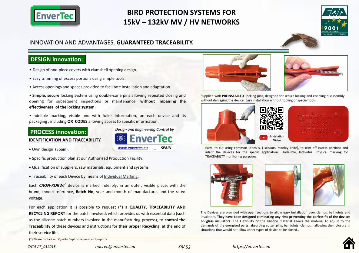
DESIGN innovation:
• Design of one-piece covers with clamshell opening design.
• Easy trimming of excess portions using simple tools.
• Access openings and spaces provided to facilitate installation and adaptation.
• Simple, secure locking system using double-cone pins allowing repeated closing and
opening for subsequent inspections or maintenance, without impairing the
effectiveness of the locking system.
• Indelible marking, visible and with fuller information, on each device and its
packaging , including QR CODES allowing access to specific information.
INNOVATION AND ADVANTAGES. GUARANTEED TRACEABILITY.
PROCESS innovation:IDENTIFICATION AND TRACEABILITY.
• Own design (Spain).
• Specific production plan at our Authorised Production Facility.
• Qualification of suppliers, raw materials, equipment and systems.
• Traceability of each Device by means of Individual Marking:
Each CAON-KORWI® device is marked indelibly, in an outer, visible place, with the
brand, model reference, Batch No, year and month of manufacture, and the rated
voltage.
For each application it is possible to request (*) a QUALITY, TRACEABILITY AND
RECYCLING REPORT for the batch involved, which provides us with essential data (such
as the silicone batch numbers involved in the manufacturing process), to control the
Traceability of these devices and instructions for their proper Recycling at the end of
their service life.
(*) Please contact our Quality Dept. to request such reports.
Supplied with PREINSTALLED locking pins, designed for secure locking and enabling disassemblywithout damaging the device. Easy installation without tooling or special tools.
Easy to cut using common utensils, ( scissors, stanley knife), to trim off excess portions andadapt the devices for the speciic application. Indelible, Individual Physical marking forTRACEABILTY monitoring purposes.
The Devices are provided with open sections to allow easy installation over clamps, ball joints andinsulators. They have been designed eliminating any rims preventing the perfect fit of the deviceson glass insulators. The Flexibility of the silicone material allows the material to adjust to thedemands of the energised parts, absorbing cotter pins, ball joints, clamps… allowing their closure insituations that would not allow other types of device to be closed..
BIRD PROTECTION SYSTEMS FOR 15kV – 132kV MV / HV NETWORKS
CATAVIF_012018 33 https://[email protected] / 52
InstalationVideo

ANTI-COLLISION DEVICES ANTI-PERCHING DEVICES
APPLICABLE REGULATIONS ON ANTI-ELECTROCUTION BIRD PROTECTION.
ANTI-COLLISION– ANTI-PERCHING DEVICES FOR USE ON 15-36kV MEDIUM VOLTAGE
DISTRIBUTION OVERHEAD LINES.
BIRD PROTECTION SYSTEMS FOR 15kV – 36kV MV / HV NETWORKS
AN
TI-CO
LLISION
AN
D A
NTI-P
ERC
HIN
GD
EVIC
ES
CATAVIF_012018 34 https://[email protected] / 52

ANTI-COLLISION DEVICES
BIRD PROTECTION SYSTEMS FOR 15kV – 36kV MV / HV NETWORKS
CATAVIF_012018 35 https://[email protected] / 52
Material: Polyvinyl Chloride (PVC) with UV
impact modifier.
Ends: Tapered
Colours: Red Similar to RAL 3031 / Other
options available upon request.

ANTI-PERCHING DEVICES
BIRD PROTECTION SYSTEMS FOR 15kV – 36kV MV / HV NETWORKS
CATAVIF_012018 36 https://[email protected] / 52
Item Currently under Distribution
BBG 2.000TM SPIKE SYSTEM INDUSTRY-LEADING PRODUCT, ECONOMICAL AND LONG-LASTINGNumber 1 – the most recommended by Architects and Public AdministrationsThe Bird·B·Gone 2.000 TM spikes are made of polycarbonate resin with ultraviolet (UV) radiation inhibitors, showing the same durability and strength as steel.They represent the best solution in terms of cost-effectiveness / permanent protection to prevent perching or nesting by birds. The spikes can be easily installed on ledges, cornices, signs, advertising billboards, electricity poles, roofs, eaves and building perimeters, water drainpipes and any other place where birds are a nuisance.Once installed, the BBG 2.000 TM spikes are virtually invisible to passers-by
BBG 2.000 TM requires no assembly, take it out of its box and install it!!!
The BIRD·B·GONE 2.000 TM spikes are not electrically conductive and do not interfere with electrical safety systems, radio frequencies or electronic transmissions. It is the spike system with the widest physical coverage in the market (20cm) but it can be adapted to cover surfaces from 3 cm. One row of BBG 2.000 TM spikes will cover an area twice as large as any other spike system. BBG 2.000 TM is available in cartons containing 10 units of one metre
length each.
» Permanent, economical and maintenance-free method» Wider physical coverage - 20cm.!» Causes no harm to birds EASY SAFE, FAST INSTALLATION » It is not electrically conductive» Protected with ultraviolet radiation inhibitors» Available in several colours including white, grey, tile red, brown and clear!!» Low installation cost» Cuts down labour time and costs» VIRTUALLY INVISIBLE
ANTI-PERCHING DEVICES
BIRD PROTECTION SYSTEMS FOR 15kV – 36kV MV / HV NETWORKS
CATAVIF_012018 37 https://[email protected] / 52
Item Currently under Distribution
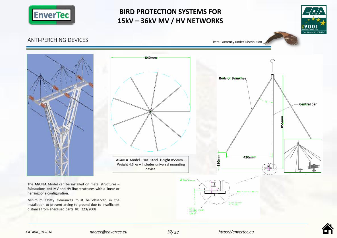
The AGUILA Model can be installed on metal structures –Substations and MV and HV line structures with a linear orherringbone configuration.
Minimum safety clearances must be observed in theinstallation to prevent arcing to ground due to insufficientdistance from energised parts. RD. 223/2008
840mm
420mm
85
5m
m
Rods or Branches
Central bar
13
0m
m
AGUILA Model –HDG Steel- Height 855mm –Weight 4.5 kg – Includes universal mounting
device.

INSTALLATION IMAGE GALLERY AND SALES DATA SHEETS
APPLICABLE LEGISLATION ON ANTI-ELECTROCUTION BIRD PROTECTION.
CAON-KORWI ® BRAND DEVICES FOR USE ON MEDIUM VOLTAGE DISTRIBUTION
OVERHEAD LINES. 15 – 45kV.
BIRD PROTECTION SYSTEMS FOR 15kV – 45kV MV / HV NETWORKS
INSTA
LLATIO
NIM
AG
EG
ALLER
Y
CATAVIF_012018 38/ 52 https://[email protected]
PR
OD
UC
TSU
PP
LYH
IGH
LIGH
TS

CAON-KORWI ®
Mod. CKSP1.2
IMAGE GALLERY – INSTALLATION PROCEDURE
SUSPENSION BIRD PROTECION KIT
Image 2: Easy trimming, installation and closing of Mod.
SWP-12 conductor cover, even at low temperatures.
Image 3: Secure attachment of SWP-12 cover to the clamp
by means of two (2) stainless steel ties.
Image 4: Easy trimming, installation and adaptation of
SPSC device to the specific application requirements. Full
insulation of Ball joint and Suspension clamp.
UTILITY:
• ENDESA DISTRIBUCION
INSTALLER COMPANY:
• ELECNOR S.A. – JAEN
LOCATION:
• Mancha Real_JAEN_Altitude 759 m
TYPE OF APPLICATION _ ( Image1 ):
• HERRINGBONE TANGENT STRUCTURE, LA-30 CONDUCTOR
DATE AND TIME:
• Nov. 2013 – 09.00h to 11.00h
WEATHER CONDITIONS:
• DRY AND SUNNY_ +1ºC / +4ºC
MATERIALS USED:
SWP-12 _ 9 m
SPSC _ 3PC..
STAINLESS TIES._ 12 PC.
SILICONE TAPE _ 9m
1
2
3
4 5
6
7
Image 5: Securing cover closure using cold vulcanising silicone
tape, Mod. X-TREME by MOCAP®
Image 6: Close-up view of taping on far end of clamp, without
covering the SWP cover outlet to allow drainage.
Image 7: Structure elements insulated in accordance with RD-
1432/2008_ BOJA 209.
Instalaciones KIT’s AVIFAUNA CAON-KORWI® – Nov.2013 [email protected] www.envertec.eu39/ 52

CAON-KORWI ®
Mod. CKST1.2
IMAGE GALLERY – INSTALLATION PROCEDURE
DEADEND BIRD PROTECTION KIT
Images 4 & 5: Easy trimming, installation and adaptation of STSC
clamp cover to the specific application requirements. Full insulation
of Ball joint and Deadend clamp. . Interaction with SAP device to
cover up existing connectors and splices, even hard-to cover ones
due to their proximity to the deadend clamp.
Images 6 & 7: Structure elements insulated in accordance with RD-
1432/2008_ BOJA 209.
UTILITY: ENDESA DISTRIBUCION
LOCATION: JAEN_PERIURBAN AREA Altitude 603 m
APPLICATION TYPE _ ( Image.1):
• HERRINGBONE DEADEND/BRANCH TOWER _ LA-56
DATE AND TIME: Nov. 2013 – 09.00h at 12h
WEATHER CONDITIONS: DRY AND SUNNY_ +3ºC / +7ºC
Instalaciones KIT’s AVIFAUNA CAON-KORWI® – Nov.2013
1
CONTRACTOR: ELECNOR S.A.
MATERIALS
USED:
SWP-12 _ 9 m
STSC _ 9PC. STAINLESS TIES._ 18PC. SILICONE TAPE_ 15m
SAP_ 9PC.
2
3
Image 2: Easy trimming, installation
and closing of Mod. SWP-12 conductor
cover, even at low temperatures
Trimming is performed working from
the structure itself, quickly and to the
lengths required by the jumper.
Image 3: Secure
attachment of SWP-12
cover to the clamp by
means of two (2) stainless
steel ties.
54
9
6 8
7
Image 8: Securing SWP cover closure using cold vulcanising
silicone tape, Mod. X-TREME by MOCAP® , showing view of
taping on cone – extra safety measure – to prevent slipping of
SWP cover along conductor, and view of far end of clamp,
without covering the SWP cover outlet to allow drainage.
Image 9: Close-up view of “flush” fit against glass insulator disc.

Installations using CAON-KORWI® Silicone Bird Protection Devices
STSC-SWP-SPSA-SPP
Mod. SWP: Capacity of conductor cover to
adapt to small radiuscurves
Mod. SPSA: Surge Arrester Cover with conductor entry/exit protected with Mod.
SWP.
Mod. SAP: Cover forAMPACT-GRIMPI. Easilyadaptable on site for use on Bypass – shunt line.
Used in combination withMod. SWP.
Mod. SPP: Cover forPolymer Post Insulator
6704113 used as Transformer Bushing
cover.
Installation without tools of the various CAON-KORWISilicone devices. Easy toinstalla working from the
tower.
Mod. SPSA: Alternative use as cover
for ARVI-32.
LOCATION:
Ubeda_PERIURBAN AREA _Altitude 748 m
TYPE OF APPLICATION:
36kV TRANSFORMER STATION_ LA-56
DATE AND TIME: Dec. 2014 – 09.00h to 12h
WEATHER CONDITIONS:
DRY AND SUNNY_ +5ºC / +7ºC
IMAGE GALLERY–ENDESA MONITORING INSPECTIONS
36kV TRANSFORMER BIRD PROTECTION
Mod. STSC (GA-1/GA-2) , used in combination with Mod. SWP-12
CATAVIF_012018 41 https://[email protected] / 52

Installations using CAON-KORWI® Silicone Bird Protection Devices
SPAV - SWP _ 36kV
LOCATION:
HINOJOSA DEL DUQUE (CORDOBA)
PERIURBAN AREA _ Altitude 545 m.
TYPE OF APPLICATION:
LIVE LINE WORK _ TOWERS WITH ARVI-32 _ ARVI-42 PIN TYPE INSULATORS
CONDUCTOR: LA-56.
DATE AND TIME: November 2016 – 12h.
WEATHER CONDITIONS:
DRY_SUNNY_ +5ºC / +9ºC.
IMAGE GALLERY –ENDESA MV GRID
BIRD PROTECTION ON ARVI-32 INSULATOR
Cover-up of conductor using mod. SWP Silicone
conductor cover
Securing Coverby means of Self-
vulcanisingSilicone Tape
mod. TPE-X10R.
Installation of mod. SPAV
SiliconeCover on
ARVI-42 pin type glassinsulators
Installation of the variousCAON-KORWI® Silicone
Devices without using tools, Easy to adapt working from
the Structure.
Installation of SPAVCover on Ceramic Pin
Type Insulators.
Close-up view of fit of model SPAVCover over model
ARVI-32 glasspin-type insulator.
Fitting ontoinsulator withouttools by means of preinstalled pins.
Middle phase ARVI-32fully covered up with
conductor length >1m on either side by means
of CAON-KORWI®Silicone covers models
SWP - SPAV.
Versatilty of model
SPAV forretrofittingStructureswith MixedPin Type
Insulators: Glass and Ceramic.
CATAVIF_012018 42 https://[email protected] / 52

Installations using CAON-KORWI® Bird Protection Devices
SPPMX - SWP _ 36kV
IMAGE GALLERY – MV POWER NETWORK. C.F.E. MEXICO -
SYSTEM PROTECTION _ POWER OUTAGE PREVENTION AND WILDLIFE
PRESERVATION.
PD LINE POST INSULATORS
LOCATION:
MEXICO D.F. - MEXICO
PERIURBAN AREA _ Altitude 2,250 m.
INSTALLATION CONDITIONS:
HOTLINE WORK_ LIVE LINE PD LINE POST INSULATORS
CONDUCTOR: ACSR 1/0.
DATE AND TIME: January 2017 – 12h.
WEATHER CONDITIONS:
DRY_SUNNY_ +9ºC / +19ºC.
Images provided by courtesy of:
- C.F.E. _ MEXICO DF
- HV TEST S.A. DE C.V.
ACSR 1/0 conductor fullyinsulated over a length
>1m ,by means of CAON-KORWI® model SPPMX
Silicone cover.
Insulation of conductor up to transformer bushinigs
by means of CAON-KORWI® model SWP
Silicone cover.
Versatilty of Mod. SPPMX336 allowinguse on different insulator types
Fitting on insulatorwithout tools, by
means of preinstalled pins
Flexibility of model SPPMX336 allows fittingsimultaneously over insulator and ACSR
conductor.
Tongue and groove closingsystem of SWP model
allows installation withouttools. Easy to fit working
from the Structure.
PURPOSE OF WORK:
Solve theconstant poweroutages causedby electrocutionof local wildlife.
Model SWP cover.
CATAVIF_012018 43 https://[email protected] / 52

Installations using CAON-KORWI® Bird Protection Devices
SPPMX - SWP _ 36kV
IMAGE GALLERY – MV POWER NETWORK. C.F.E. MEXICO -
SYSTEM PROTECTION _ POWER OUTAGE PREVENTION AND WILDLIFE
PRESERVATION.
COVERS FOR PD LINE POST INSULATORS
Model SWP silicone cover.
Model SWP silicone cover
LOCATION AND DATE:
AGUASCALIENTES – MEXICO - February, 2017 .
ZEPA – Special bird protection area.
PROGRAMME: PRESERVATION- GPS MONITORINGOF IMPERIAL EAGLE.
SCOPE OF APPLICATION:
Retrofitting of ANTI-ELECTROCUTION devices onlines with PD LINE POST insulators and ACSRconductors.
Images provided by courtesy of:
HV TEST S.A. DE C.V.
Programme sponsored by:
HV TEST S.A. DE C.V.
CATAVIF_012018 44 https://[email protected] / 52

MV Deadend Structure – 36kV
Close-up view of fit on Polymer Insulator pin showing marking and
Batch Number from the ground using 21x Zoom
Installation Work in Jaen ProvinceAndalusia_Spain
Installations using CAON-KORWI® Silicone Bird Protection Devices
STSC - SWP
CATAVIF_012018 45 https://[email protected] / 52

SUPPLY HISTORY HIGHLIGHTS. ESTABLISHED PRODUCT.
BIRD PROTECTION SYSTEMS FOR 15kV – 36kV MV / HV NETWORKS
Power line elements fitted withCAON-KORWI ® Silicone Protective
Devices
CATAVIF_012018 46 https://[email protected] / 52
More than 6,500 deadend structuresprotected with ourSTSC – SWP covers
CAON®-KORWI® Silicone CoversPerfect balance between
CONSISTENCY and FLEXIBILITY
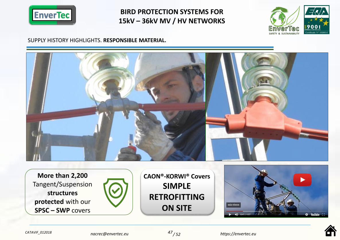
SUPPLY HISTORY HIGHLIGHTS. RESPONSIBLE MATERIAL.
BIRD PROTECTION SYSTEMS FOR 15kV – 36kV MV / HV NETWORKS
CATAVIF_012018 47 https://[email protected] / 52
CAON®-KORWI® Covers
SIMPLE RETROFITTING
ON SITE
More than 2,200 Tangent/Suspension
structuresprotected with ourSPSC – SWP covers

SUPPLY HISTORY HIGHLIGHTS. ASSURED TRACEABILITY.
BIRD PROTECTION SYSTEMS FOR 15kV – 36kV MV / HV NETWORKS
CATAVIF_012018 48 https://[email protected] / 52
More than 97,000 metres of conductor protected
with our SWP cover
SWP Cover
The most sought-after conductor cover due to its Safety, Flexibility,
Swift Installation and Performance on Small Radius Curves
Contained dimensions and
Streamlined Geometry toensure they Remain in
original location.
Secure and fast closing withno tools required
Easy to trim and adaptstraight on conductor even
at low temperatures.

SUPPLY HISTORY HIGHLIGHTS. INNOVATION ON HIGH PERFORMANCE COVERS
BIRD PROTECTION SYSTEMS FOR 15kV – 36kV MV / HV NETWORKS
CATAVIF_012018 49 https://[email protected] / 52
Highly flexible covers, easy toadapt on site
More than 10,000 AMPACT type splices
protected with ourSAP covers
More than 7,700 medium voltage valve
surge arresters protectedwith our SPSA covers

SUPPLY HISTORY HIGHTLIGTS. SIMPLE AND SECURE CLOSURE SYSTEMS.
BIRD PROTECTION SYSTEMS FOR 15kV – 36kV MV / HV NETWORKS
CATAVIF_012018 50 https://[email protected] / 52
More than 1,200 MV Transformers protected with our
SPP device

SPECIFIC ADVANCED FORMULATION SILICONE.
“ […] the dielectric strength improves with ageing.“ (*)
The Ongoing Field Installation Performance Monitoring carried out by us over the past 5 years onour CAON®-KORWI® brand Silicone covers, together with the positive results in the recently carriedout OZONE RESISTANCE tests according to IEC EN 60811-403:2012, as well as the remarkableShore A Hardness and Dielectric Strength measurements obtained after passing the 1000h
ACCELERATED WEATHERING test as per IEC EN 60243-1:2013(*) allow us to assure a Unique andOutstanding Enduring Performance of our Covers.
(*) The initial Dielectric Strength value of our silicone is 20kV/mm, which improves up to 23.14kV/mmafter the test.
The initial Shore A hardness value is 69, which improves up to a Shore A value of 71 after passing the test.Source: Report dated April 2018 – CENTRO DE ENSAYOS INNOVACIÓN Y SERVICIOS – CEIS.
ONGOING INSTALLATION PERFORMANCE ASSESSMENT REPORT: YEARS 2013-2014-2015-2016-2017
ESTIMATED DURABILITY GUARANTEE > 20 YEARS.
2013/11/27
a
Fig.1 - 2013
Fig.2 - 2014 Fig.3 - 2015
The use of utility approved fixing and closure securing elements in combination with the Mod. SWP Silicone protective cover ensures optimum performance of the installation,enduring over time. - Fig. 1: Use of self-welding silicone tape (a) on deadend phase. The application points are specified in the installation manual provided with each device. Fig. 2: Securing ofSWP cover to the cone forming part of the Mod.STC clamp cover (a). Fig. 2: Use of self-welding silicone tape (a) and stainless steel fixing ties (b . The application points are specified in theinstallation manual provided with each device.
a
b
Figs. 1, 2 , 3 , 4 & Fig. 5: Photos taken at one-year intervals of thesame deadend phase: 2013 – 2014 – 2015-2016-2017.
Fig.4 - 2016
2017.12.03Fig.5 - 2017
https://envertec.euCATAVIF_012018
Total absence of incidents or signs of weather degradation.
51/ 52

https://envertec.eu
ENVERTEC S.L.Pol. Ind. LA FUENTE
C/ Huelva, parcela nº 1018340 – Fuente Vaqueros
Granada (Spain)
+34 958 511 669
BIRD PROTECTION SYSTEMS FOR 15kV – 132kV MV / HV NETWORKS
Supplier No 116.563
Supplier No 643.478
Nicaragua
MV Insulators & Switchgear
ENGINEERING DEVELOPMENT DEPT. AND WAREHOUSE
CATAVIF_012018 52
THANK YOU
ENVERTEC-CAON PRODUCTION FACILITY
/ 52