prevention of barite sag in water-based drilling fluids by
TRANSCRIPT

sustainability
Article
Prevention of Barite Sag in Water-Based DrillingFluids by A Urea-Based Additive for DrillingDeep Formations
Abdelmjeed Mohamed 1 , Saad Al-Afnan 1, Salaheldin Elkatatny 1,* andIbnelwaleed Hussein 2
1 College of Petroleum Engineering and Geosciences, King Fahd University of Petroleum & Minerals,Dhahran 31261, Saudi Arabia; [email protected] (A.M.); [email protected] (S.A.-A.)
2 Gas Processing Center, College of Engineering, Qatar University, Doha 2713, Qatar; [email protected]* Correspondence: [email protected]; Tel.: +966-594663692
Received: 13 February 2020; Accepted: 26 March 2020; Published: 30 March 2020�����������������
Abstract: Barite sag is a challenging phenomenon encountered in deep drilling with barite-weightedfluids and associated with fluid stability. It can take place in vertical and directional wells, whether indynamic or static conditions. In this study, an anti-sagging urea-based additive was evaluated toenhance fluid stability and prevent solids sag in water-based fluids to be used in drilling, completion,and workover operations. A barite-weighted drilling fluid, with a density of 15 ppg, was usedwith the main drilling fluid additives. The ratio of the urea-based additive was varied in the range0.25–3.0 vol.% of the total base fluid. The impact of this anti-sagging agent on the sag tendencywas evaluated at 250 ◦F using vertical and inclined sag tests. The optimum concentration of theanti-sagging agent was determined for both vertical and inclined wells. The effect of the urea-additiveon the drilling fluid rheology was investigated at low and high temperatures (80 ◦F and 250 ◦F).Furthermore, the impact of the urea-additive on the filtration performance of the drilling fluid wasstudied at 250 ◦F. Adding the urea-additive to the drilling fluid improved the stability of the drillingfluid, as indicated by a reduction in the sag factor. The optimum concentration of this additive wasfound to be 0.5–1.0 vol.% of the base fluid. This concentration was enough to prevent barite sag inboth vertical and inclined conditions at 250 ◦F, with a sag factor of around 0.5. For the optimumconcentration, the yield point and gel strength (after 10 s) were improved by around 50% and 45%,respectively, while both the plastic viscosity and gel strength (after 10 min) were maintained atthe desired levels. Moreover, the anti-sagging agent has no impact on drilling fluid density, pH,or filtration performance.
Keywords: barite sag; water-based drilling fluid; anti-sagging agent; urea-based additive
1. Introduction
Drilling fluids are introduced to a formation to fulfill many functions, but mainly to control theformation pressure [1,2]. Overbalanced drilling is a common technique for well control, where thedrilling fluid provides a hydrostatic pressure higher than the formation pressure. To achieve thisfunction, the required fluid density is maintained by adding weighting materials to the drilling fluid.There are many weighting materials introduced to increase the drilling fluid density, such as barite,siderite, magnetite, iron oxides, ilmenite, hematite, and calcite [2–10]. Barite (BaSO4) is a commonweighting material used to attain the desired density of drilling and completion fluids [2,11] becausebarite has a high density, low production cost, and less environmental impact [12,13]. However,the invasion of solid particles causes formation damage and reduces the permeability near thewellbore [14,15]. Another issue encountered with barite-weighted fluids is solids sag or barite sag.
Sustainability 2020, 12, 2719; doi:10.3390/su12072719 www.mdpi.com/journal/sustainability

Sustainability 2020, 12, 2719 2 of 19
Barite sag is a phenomenon that occurs when barite particles separate from the liquid phase andsettle down, causing variations in fluid density. These variations may cause a loss of well control thatcould lead to severe kick [16,17]. Barite sag is a serious issue encountered in vertical and directionalwells, but more commonly in directional wells. It can occur under either static conditions or dynamicconditions, particularly at low shear rates [16,18]. Several cases of barite sag have been encounteredin drilling and completion operations [19]. For instance, a severe kick was detected during a wellcompletion operation in the North Sea. In that operation, oil-based mud was used as a completionfluid. The kick resulted due to barite sag, with a significant contribution of well geometry to the solidssag issue [20]. However, the consequences of barite sag can be mitigated by maintaining the drillingfluid rheology, implementing sound strategies, and training rig personnel [19]. Using drilling fluidadditives is the most effective solution to the problem of barite sag as it greatly enhances the drillingfluid rheology and stability, which are considered the main controlling factors of barite sag.
Many studies have been conducted to mitigate the solids sag phenomenon in both oil-basedand water-based drilling fluids by adding drilling fluid additives and controlling the weightingmaterial. Temple et al. [21] introduced a new method to enhance the stability of oil-based fluids withoutincreasing the drilling fluid viscosity. Polyalkyl methacrylate, with low molecular weight, was added tothe drilling fluid, while no copolymer such as vinylpyrrolidone was used. Davis et al. [22] introduced anew method to prevent solids sag in oil-based fluid by using a sag stability enhancer. The sag stabilityenhancer comprises polyethylene glycol (PEG) that has a molecular weight equal to or higher than200 g/mol. Basfar et al. [23] and Elkatatny [24] evaluated a new copolymer to mitigate solids sag inoil-based mud at high temperatures, up to 350 ◦F. Just 1 lbm/bbl of the copolymer was enough tosolve the barite sag issue in both vertical and inclined conditions. Boyou et al. [25] performed anexperimental study on the use of nano-silica to improve the suspension capability of water-based fluidsfor directional well drilling applications. Different concentrations of nano-silica were used, and theexperiments were conducted in a flow loop setup at different inclination angles. It was found thatnano-silica increased the colloidal interaction with cuttings; therefore, the cuttings’ transport efficiencywas significantly improved in all inclination angles.
Another technique for reducing barite sag is to modify the weighting material without adding astability enhancer to the drilling fluid. Alabdullatif et al. [26] proposed a combination of manganesetetra oxide (Mn3O4) and barite as a weighting material in water-based kill fluid to mitigate theproblem of barite sag. Adding Mn3O4 to the fluid formulation effectively enhanced the fluid stabilityand minimized the possibility of solids sag, particularly over a long time under static conditions.Mohamed et al. [13] investigated the impact of barite particle size reduction on the stability ofwater-based mud using the sag test and zeta potential measurements. It was concluded that decreasingthe barite particle size to micronized size slightly enhances the drilling fluid stability, but it doesnot eliminate the sag issue. Basfar et al. [27] and Mohamed et al. [28] studied the effect of using abarite-ilmenite combined weighting material on the properties of water-based and oil-based drillingfluids. It was found that the combined weighting material greatly enhanced the rheological propertiesand the stability of the drilling fluid and prevented solids sag in both vertical and inclined conditions.However, using a combined weighting agent would add more cost and introduce another challengeto the drilling fluid operation, that is, the removal of composite filter cake, as the weighting materialcontributes greatly to filter cake formation, at 70–80 wt.% [29].
For successful operations, the rheology of the drilling fluid should be monitored and maintainedthroughout drilling operations by adding the proper drilling fluid additives such as viscosifiers,thinners, and stability enhancers. Most of the previous studies related to barite sag were conducted onoil-based fluids, and barite sag in water-based drilling fluids has received little attention. The previousstudies focused on measuring the sag tendency and tried to correlate the results with the rheologicaland viscoelastic properties (see Table 1).
In this study, an anti-sagging additive is introduced as another solution to enhance fluid stabilityand eliminate solids sag in water-based drilling, completion, and workover fluids, without introducing
Sustainability 2020, 12, 2719 3 of 19
a combined weighting material to the drilling fluid that would lead to a complex solids system, oradding high cost to the drilling operation, because very low concentrations of this additive are required.This additive is a modified urea solution and was originally used in water-based applications foranti-sag in other industries, such as coatings, lubricants, foundries, and detergent industries [30,31].The extension of the application of this additive to water-based drilling fluids for deep wells isinvestigated. First, the materials used are described, and the experimental procedure and conditions toconduct this work are explained. Then, the results of this study are discussed, and lastly, the findingsof this work are summarized.
Table 1. Summary of the methods used to prevent barite sag.
Study Method Drilling Fluid System Findings
Temple et al., 2004 Adding polyalkylmethacrylate Oil-based The optimum concentration to prevent barite sag was 0.5–3 lb/bbl.
Davis et al., 2017 Adding polyethyleneglycol (PEG) Oil-based A concentration of 0.5 lb/bbl was enough to eliminate barite sag.
Basfar et al., 2018 Adding a copolymer Oil-basedA concentration of 1 lbm/bbl of copolymer was enough to prevent barite
sag up to 350◦F.Elkatatny, 2019
Boyou et al., 2019 Adding nano-silica Water-based The cuttings’ transport efficiency was significantly improved in differentinclination angles.
Alabdullatif et al., 2015Adding a combination of
Mn3O4 and barite as aweighting material
Water-based Mn3O4 effectively enhanced the fluid stability and minimized barite sag.
Mohamed et al., 2017 Using micronized barite Water-based Micronized barite improved the stability, but it did not eliminate barite sag.
Basfar et al., 2019 Using a barite-ilmenitecombined weighting
material
Water-based A proportion of 50 wt.% ilmenite (of the total weighting material) wasadequate to prevent barite sag.
Mohamed et al., 2019 Oil-based A proportion of 40 wt.% ilmenite (of the total weighting material) wasadequate to prevent barite sag.
2. Materials
The barite sample, obtained from a service company, was used as a weighting material forwater-based drilling fluid. The elemental composition of the barite sample was obtained using theX-ray fluorescence technique, XRF. The barite sample mainly contains 82 wt.% barium, 12.6 wt.% sulfur,1.99 wt.% silicon, and 1.33 wt.% iron, with small traces (<1 wt.%) of other elements, such as potassium,calcium, nickel, copper, and strontium (Table 2). The particle size distribution of this sample wasmeasured using a particle size analyzer. The sample exhibited a normal distribution with a D10 of4.5 µm, average particle size (D50) of 30 µm, D75 of 52 µm, and D90 of 79 µm (Figure 1). Defoamer(D-Air 4000L™) was added to the water to prevent the formation of foam. The defoamer comprises anamide of carboxylic acid, a polypropylene glycol, an ethoxylated and propoxylated fatty alcohol, anethoxylated alcohol comprising from 3 carbons to 6 carbons, and a hydrophobic silica in an amountof up to about 3% by weight of the defoaming composition. Soda ash was used to maintain theconcentration of calcium in the water. Xanthan gum polymer and bentonite were used as viscosifiersto improve the drilling fluid rheology. Starch and Polyanionic Cellulose Regular Viscosity (PAC-R)were used to control fluid loss. Clay stabilization was maintained by adding potassium chloride to thedrilling fluid. Calcium carbonate was used as a bridging agent, and potassium hydroxide was used tocontrol the pH of the drilling fluid [7].
The anti-sagging additive was added in different concentrations, 0.25–3 vol.% of the total base fluid,to improve the stability of the drilling fluid and prevent solid settlement. It was added right before theweighting material, barite, and mixed for 10 min. This additive works as an anti-sagging agent, and itis a solution of modified urea that mainly contains pentanoic acid, 5-(dimethylamino)-2-methyl-5-oxo-,methyl ester, and lithium chloride (Table 3). It was obtained from a service company, and it wasoriginally used in coatings, lubricants, foundries, and detergent industries as an anti-sagging agent. Ithas a density of 1.11 g/cc and dynamic viscosity of 700 mPa.s at ambient temperature, with completesolubility in water.

Sustainability 2020, 12, 2719 4 of 19
Table 2. The elemental composition of the barite sample measured by the X-ray fluorescence(XRF) technique.
Element wt.%
Si 1.9916S 12.6341K 0.6331Ca 0.1109Fe 1.3338Ni 0.0157Cu 0.0354Sr 0.5518
Mo 0.017Ba 82.6171Ta 0.023Pb 0.0366
Sustainability 2020, 11, x FOR PEER REVIEW 4 of 21
K 0.6331
Ca 0.1109
Fe 1.3338
Ni 0.0157
Cu 0.0354
Sr 0.5518
Mo 0.017
Ba 82.6171
Ta 0.023
Pb 0.0366
The anti-sagging additive was added in different concentrations, 0.25–3 vol.% of the total base
fluid, to improve the stability of the drilling fluid and prevent solid settlement. It was added right
before the weighting material, barite, and mixed for 10 min. This additive works as an anti-sagging
agent, and it is a solution of modified urea that mainly contains pentanoic acid, 5-(dimethylamino)-
2-methyl-5-oxo-, methyl ester, and lithium chloride (Table 3). It was obtained from a service
company, and it was originally used in coatings, lubricants, foundries, and detergent industries as an
anti-sagging agent. It has a density of 1.11 g/cc and dynamic viscosity of 700 mPa.s at ambient
temperature, with complete solubility in water.
Figure 1. The particle size distribution of the barite sample (D50 = 30 microns).
Table 3. The properties and main components of the anti-sagging additive.
Parameter Description
Main components [Pentanoic acid, 5-(dimethylamino)-2-methyl-5-oxo-, methyl ester] 58–59%
[Lithium chloride] 1–2%
Density 1.11 g/cc
Dynamic viscosity 770 mPa.s
Water solubility Completely miscible
Flash point > 212 °F
3. Experimental Work
3.1. Fluid Preparation
A barite-weighted drilling fluid, 15 ppg, was prepared using the main drilling fluid additives.
Drilling fluid additives were added individually and mixed for a specific time initially by adding
viscosifiers (xanthan gum polymer and bentonite). The mixing started with 10,000 rpm rotational
Figure 1. The particle size distribution of the barite sample (D50 = 30 microns).
Table 3. The properties and main components of the anti-sagging additive.
Parameter Description
Main components• [Pentanoic acid, 5-(dimethylamino)-2-methyl-5-oxo-, methyl ester] 58–59%• [Lithium chloride] 1–2%
Density 1.11 g/ccDynamic viscosity 770 mPa.s
Water solubility Completely miscibleFlash point > 212 ◦F
3. Experimental Work
3.1. Fluid Preparation
A barite-weighted drilling fluid, 15 ppg, was prepared using the main drilling fluid additives.Drilling fluid additives were added individually and mixed for a specific time initially by adding
Sustainability 2020, 12, 2719 5 of 19
viscosifiers (xanthan gum polymer and bentonite). The mixing started with 10,000 rpm rotationalspeed, then increased to 14,000 rpm and then to 17,000 rpm as the viscosity built up. Afterward, otheradditives were added to the drilling fluid following the fluid formulation used (Table 4). Followingthe same procedure, many fluid samples were prepared by adding different concentrations of theurea-additive to the drilling fluid formulation (0.25, 0.5, 1.0, 1.5, 2.0, and 3.0 vol.% of the total basefluid). The urea-additive was added right before adding the weighting material and mixed for 10 min.
Table 4. Drilling fluid formulation (lab scale).
Component Amount, g Mixing Time, min Function
Water 245 - BaseDefoamer (D-Air 4000L™) 0.08 1 Anti-foam agent
Soda ash 0.5 1 Maintains calcium concentrationXanthan gum polymer 1.5 20 Viscosity control
Bentonite 4 10 Viscosity controlPotassium hydroxide 0.5 1 pH adjustment
Starch 6 10 Fluid loss controlPAC-R 1 10 Fluid loss control
Potassium chloride 20 10 Clay stabilizationCalcium carbonate 5 10 Bridging agent
Barite 350 10 Weighting material
3.2. Sag Tests
First, the sag test was conducted using the base drilling fluid at two different temperatures, 200 and250 ◦F, to identify the temperature at which barite sag occurs. Then, the effect of the urea-additiveon the sag tendency was evaluated at that temperature. The experimental setup consists of Teflonliner, aging cell, cell holder, and oven (Figure 2). First, the drilling fluid sample was agitated using thedrilling fluid mixer for 10 min, and then poured in the cell. The fluid samples were pressurized with500 psi using nitrogen and heated to 200/250 ◦F for 24 h under static conditions, vertical and inclined(45◦). After 24 h, the cell was cooled and depressurized; then, a syringe was used to take a 10 cm3
sample from the top and the bottom fluid, and the density of those samples was measured. Then, thesag factor was obtained using Equation (1). Sag tests were repeated three times to ensure the accuracyof the measurements, and the presented data are the average of the measurements.
Sag Factor =ρBottom
ρBottom + ρTop(1)
where ρBottom and ρTop are the density of the bottom and top fluid samples in ppg.
Sustainability 2020, 11, x FOR PEER REVIEW 5 of 21
speed, then increased to 14,000 rpm and then to 17,000 rpm as the viscosity built up. Afterward, other
additives were added to the drilling fluid following the fluid formulation used (Table 4). Following
the same procedure, many fluid samples were prepared by adding different concentrations of the
urea-additive to the drilling fluid formulation (0.25, 0.5, 1.0, 1.5, 2.0, and 3.0 vol.% of the total base
fluid). The urea-additive was added right before adding the weighting material and mixed for 10
min.
Table 4. Drilling fluid formulation (lab scale).
Component Amount, g Mixing Time, min Function
Water 245 - Base
Defoamer (D-Air 4000L™) 0.08 1 Anti-foam agent
Soda ash 0.5 1 Maintains calcium concentration
Xanthan gum polymer 1.5 20 Viscosity control
Bentonite 4 10 Viscosity control
Potassium hydroxide 0.5 1 pH adjustment
Starch 6 10 Fluid loss control
PAC-R 1 10 Fluid loss control
Potassium chloride 20 10 Clay stabilization
Calcium carbonate 5 10 Bridging agent
Barite 350 10 Weighting material
3.2. Sag Tests
First, the sag test was conducted using the base drilling fluid at two different temperatures, 200
and 250 ℉ , to identify the temperature at which barite sag occurs. Then, the effect of the urea-additive
on the sag tendency was evaluated at that temperature. The experimental setup consists of Teflon
liner, aging cell, cell holder, and oven (Figure 2). First, the drilling fluid sample was agitated using
the drilling fluid mixer for 10 min, and then poured in the cell. The fluid samples were pressurized
with 500 psi using nitrogen and heated to 200/250 ℉ for 24 h under static conditions, vertical and
inclined (45˚). After 24 h, the cell was cooled and depressurized; then, a syringe was used to take a 10
cm3 sample from the top and the bottom fluid, and the density of those samples was measured. Then,
the sag factor was obtained using Equation (1). Sag tests were repeated three times to ensure the
accuracy of the measurements, and the presented data are the average of the measurements.
𝑆𝑎𝑔 𝐹𝑎𝑐𝑡𝑜𝑟 =𝜌𝐵𝑜𝑡𝑡𝑜𝑚
𝜌𝐵𝑜𝑡𝑡𝑜𝑚 + 𝜌𝑇𝑜𝑝 (1)
where ρBottom and ρTop are the density of the bottom and top fluid samples in ppg.
According to industry practices, the acceptable value of the sag factor is between 0.5 and 0.53,
while a higher value indicates solids settlement [26,32].
Figure 2. Experimental apparatus for the static sag test: a) vertical and b) inclined (45˚) [24].
3.3. Rheology Measurement
Figure 2. Experimental apparatus for the static sag test: (a) vertical and (b) inclined (45◦) [24].

Sustainability 2020, 12, 2719 6 of 19
According to industry practices, the acceptable value of the sag factor is between 0.5 and 0.53,while a higher value indicates solids settlement [26,32].
3.3. Rheology Measurement
After preparing the drilling fluid, the drilling fluid density was measured, and the rheologymeasurements were conducted at low temperature (80 ◦F) and high temperature with high pressure(250 ◦F and 2000 psi) to study the effect of the urea-additive on the drilling fluid rheology in thoseconditions. The measured properties are yield point (YP), plastic viscosity (PV), and gel strength after10 s and 10 min. Plastic viscosity and yield point are calculated by Equations (2) and (3) using the dialreadings at 300 RPM (φ300) and 600 RPM (φ600), while the gel strength data were obtained from thedirect dial reading at 3 RPM after 10 s, 10 min, and 30 min of static gel time.
PV = ∅600 −∅300 (2)
YP = ∅300 − PV (3)
3.4. HPHT Filtration Experiments
The filtration performance of the drilling fluid and the filter cake properties were evaluatedby conducting a series of filtration experiments. The test was conducted at 250 ◦F and 300 psidifferential pressure, using a 50-micron ceramic filter disc as a filtration medium. The high-pressurehigh-temperature (HPHT) filtration cell was heated to 250 ◦F under a pressure of 300 psi (Table 5).Afterward, the experiment was started, and the filtrate volume was measured with time. After 30min, the experiment was stopped, the filter cake was weighted, and the thickness of the filter cakewas measured.
Table 5. Filtration experiment parameters.
Parameter Description
Fluid volume 350 cm3
Pressure 300 psiTemperature 250 ◦F
Experiment duration 30 minCeramic filter disc 50-micron
4. Results and Discussions
4.1. Sag Tests
First, the drilling fluid density and the pH were measured for the drilling fluid samples. It wasfound that adding the anti-sagging additive at a concentration up to 3 vol.% of the total base fluid hadno impact on drilling fluid density and pH. The density was around 15 ppg for all fluid samples, andthe pH ranged between 9 and 10.
The sag performance of the base drilling fluid under vertical and inclined conditions was measuredat two different temperatures, 200 and 250 ◦F. For the inclined sag test, the degree of inclination was setat 45◦ to simulate the worst scenario because the settling process is accelerated when the inclinationis greater than 30◦ [33]. At 200 ◦F, the base drilling fluid exhibited a good sag performance in bothcases, vertical and inclined, and the sag factor was within the safe range (0.5–0.53) with values of 0.51and 0.52, respectively (Figure 3). In contrast, the base fluid showed a poor sag performance at 250 ◦F.The sag factor was higher than 0.53 for both inclined and vertical conditions; therefore, barite sag ishighly anticipated.

Sustainability 2020, 12, 2719 7 of 19
Sustainability 2020, 11, x FOR PEER REVIEW 7 of 21
disperse the particles in the colloidal system and improved the suspension capability of the drilling
fluid [34].
Figure 3. Effect of temperature on sag for base fluid under vertical and inclined conditions.
Figure 4. Effect of the urea-additive on sag under vertical conditions (250 °F).
Figure 3. Effect of temperature on sag for base fluid under vertical and inclined conditions.
Under vertical conditions, adding the anti-sagging additive to the drilling fluid formulationshowed a significant improvement in the drilling fluid stability at 250 ◦F, the sag factor was withinthe acceptable range (0.5–0.53) for all the drilling fluid samples, and adding just 0.25 vol.% of theanti-sagging additive was adequate to prevent barite sag (Figure 4). Conversely, when the sag test wasconducted under inclined conditions, 45◦, Figure 5 shows that adding 0.25 vol.% of the anti-saggingadditive reduced the sag factor from 0.63 to 0.54, and adding 0.5–1 vol.% was adequate to bring thesag factor into the safe zone (0.5–0.53); thus, barite sag is unlikely to occur under those conditions.The improvement in the sag tendency of the drilling fluid is because the urea-additive helped dispersethe particles in the colloidal system and improved the suspension capability of the drilling fluid [34].
Sustainability 2020, 11, x FOR PEER REVIEW 7 of 21
disperse the particles in the colloidal system and improved the suspension capability of the drilling
fluid [34].
Figure 3. Effect of temperature on sag for base fluid under vertical and inclined conditions.
Figure 4. Effect of the urea-additive on sag under vertical conditions (250 °F). Figure 4. Effect of the urea-additive on sag under vertical conditions (250 ◦F).

Sustainability 2020, 12, 2719 8 of 19
Sustainability 2020, 11, x FOR PEER REVIEW 8 of 21
Figure 5. Effect of the urea-additive on sag under inclined conditions, 45° (250 °F).
4.2. Rheological Analysis
The shear stress measured at room temperature (80 °F) was plotted versus the shear rate for all
the drilling fluid samples (Figure 6). It was observed that the drilling fluid samples follow the
Bingham plastic model. Increasing the concentration of the anti-sagging additive increased the shear
stress values and shifted the consistency curve upward with almost a constant slope. This shift
indicates a significant increase in yield point (intercept with the y-axis) without increasing the plastic
viscosity (slope).
Figure 6. Effect of the urea-additive on the drilling fluid rheology (80 °F).
The effect of adding the urea-additive on the rheological properties was evaluated by measuring
yield point, plastic viscosity, and gel strength at 10 s and 10 min. At room temperature, a significant
increase in the yield point and gel strength values after 10 s was observed as the concentration
increased (around 40%–50% for 0.5–1.0 vol.%), reflecting an enhancement in the drilling fluid’s ability
to suspend solid particles (Figure 7). In contrast, the anti-sagging additive had no impact on plastic
Figure 5. Effect of the urea-additive on sag under inclined conditions, 45◦ (250 ◦F).
4.2. Rheological Analysis
The shear stress measured at room temperature (80 ◦F) was plotted versus the shear rate forall the drilling fluid samples (Figure 6). It was observed that the drilling fluid samples follow theBingham plastic model. Increasing the concentration of the anti-sagging additive increased the shearstress values and shifted the consistency curve upward with almost a constant slope. This shiftindicates a significant increase in yield point (intercept with the y-axis) without increasing the plasticviscosity (slope).
Sustainability 2020, 11, x FOR PEER REVIEW 8 of 21
Figure 5. Effect of the urea-additive on sag under inclined conditions, 45° (250 °F).
4.2. Rheological Analysis
The shear stress measured at room temperature (80 °F) was plotted versus the shear rate for all
the drilling fluid samples (Figure 6). It was observed that the drilling fluid samples follow the
Bingham plastic model. Increasing the concentration of the anti-sagging additive increased the shear
stress values and shifted the consistency curve upward with almost a constant slope. This shift
indicates a significant increase in yield point (intercept with the y-axis) without increasing the plastic
viscosity (slope).
Figure 6. Effect of the urea-additive on the drilling fluid rheology (80 °F).
The effect of adding the urea-additive on the rheological properties was evaluated by measuring
yield point, plastic viscosity, and gel strength at 10 s and 10 min. At room temperature, a significant
increase in the yield point and gel strength values after 10 s was observed as the concentration
increased (around 40%–50% for 0.5–1.0 vol.%), reflecting an enhancement in the drilling fluid’s ability
to suspend solid particles (Figure 7). In contrast, the anti-sagging additive had no impact on plastic
Figure 6. Effect of the urea-additive on the drilling fluid rheology (80 ◦F).
The effect of adding the urea-additive on the rheological properties was evaluated by measuringyield point, plastic viscosity, and gel strength at 10 s and 10 min. At room temperature, a significant

Sustainability 2020, 12, 2719 9 of 19
increase in the yield point and gel strength values after 10 s was observed as the concentration increased(around 40%–50% for 0.5–1.0 vol.%), reflecting an enhancement in the drilling fluid’s ability to suspendsolid particles (Figure 7). In contrast, the anti-sagging additive had no impact on plastic viscosityand gel strength values after 10 min. All the drilling fluid samples had a plastic viscosity of around25 cP, and a gel strength (after 10 min) of around 45 lbf/100ft2. When YP/PV ratios were calculated forall drilling fluid samples (Figure 8), it was found that as the concentration of the anti-sagging agentincreased, the YP/PV ratio increased, indicating a more stable drilling fluid, which confirms the sagtest results.
Sustainability 2020, 11, x FOR PEER REVIEW 9 of 21
viscosity and gel strength values after 10 min. All the drilling fluid samples had a plastic viscosity of
around 25 cP, and a gel strength (after 10 min) of around 45 lbf/100ft2. When YP/PV ratios were
calculated for all drilling fluid samples (Figure 8), it was found that as the concentration of the anti-
sagging agent increased, the YP/PV ratio increased, indicating a more stable drilling fluid, which
confirms the sag test results.
Figure 7. Effect of the urea-additive on the rheological properties of the drilling fluid (80 °F).
Figure 8. Effect of the urea-additive on the yield point–plastic viscosity ratio (80 °F).
The yield-stress characteristics affect many drilling fluid issues such as hole cleaning, barite sag,
surge and swab pressures, and equivalent circulating density [35]. YP/PV was proposed as a tool to
evaluate drilling fluid stability [36]. From the rheology measurements, as the concentration of the
anti-sagging additive was increased, the YP/PV ratio increased, which reflects an enhancement in
fluid stability and in the drilling fluid’s capability to suspend solid particles. However, adding high
concentrations of the anti-sagging additive will require higher pumping pressure to start the drilling
fluid circulation because of the high yield point and gel strength values [37]. Moreover, very high
YP/PV ratios indicate mud coagulation and flocculation [36]. Since adding just 0.5–1 vol.% of the anti-
sagging additive prevented barite sag in both vertical and inclined conditions, 0.5–1 vol.% can be
Figure 7. Effect of the urea-additive on the rheological properties of the drilling fluid (80 ◦F).
Sustainability 2020, 11, x FOR PEER REVIEW 9 of 21
viscosity and gel strength values after 10 min. All the drilling fluid samples had a plastic viscosity of
around 25 cP, and a gel strength (after 10 min) of around 45 lbf/100ft2. When YP/PV ratios were
calculated for all drilling fluid samples (Figure 8), it was found that as the concentration of the anti-
sagging agent increased, the YP/PV ratio increased, indicating a more stable drilling fluid, which
confirms the sag test results.
Figure 7. Effect of the urea-additive on the rheological properties of the drilling fluid (80 °F).
Figure 8. Effect of the urea-additive on the yield point–plastic viscosity ratio (80 °F).
The yield-stress characteristics affect many drilling fluid issues such as hole cleaning, barite sag,
surge and swab pressures, and equivalent circulating density [35]. YP/PV was proposed as a tool to
evaluate drilling fluid stability [36]. From the rheology measurements, as the concentration of the
anti-sagging additive was increased, the YP/PV ratio increased, which reflects an enhancement in
fluid stability and in the drilling fluid’s capability to suspend solid particles. However, adding high
concentrations of the anti-sagging additive will require higher pumping pressure to start the drilling
fluid circulation because of the high yield point and gel strength values [37]. Moreover, very high
YP/PV ratios indicate mud coagulation and flocculation [36]. Since adding just 0.5–1 vol.% of the anti-
sagging additive prevented barite sag in both vertical and inclined conditions, 0.5–1 vol.% can be
Figure 8. Effect of the urea-additive on the yield point–plastic viscosity ratio (80 ◦F).
The yield-stress characteristics affect many drilling fluid issues such as hole cleaning, barite sag,surge and swab pressures, and equivalent circulating density [35]. YP/PV was proposed as a tool toevaluate drilling fluid stability [36]. From the rheology measurements, as the concentration of theanti-sagging additive was increased, the YP/PV ratio increased, which reflects an enhancement in

Sustainability 2020, 12, 2719 10 of 19
fluid stability and in the drilling fluid’s capability to suspend solid particles. However, adding highconcentrations of the anti-sagging additive will require higher pumping pressure to start the drillingfluid circulation because of the high yield point and gel strength values [37]. Moreover, very highYP/PV ratios indicate mud coagulation and flocculation [36]. Since adding just 0.5–1 vol.% of theanti-sagging additive prevented barite sag in both vertical and inclined conditions, 0.5–1 vol.% canbe considered as the optimum concentration of the anti-sagging additive. Adding more than thisconcentration would cause additional pressure losses because the yield point affects the pressure lossesfor Bingham plastic fluids. Moreover, increasing the concentration of the urea-additive would alsoincrease the total cost of the drilling operations.
Furthermore, the drilling fluid rheology for the base fluid and with 0.5–1.0 vol.% of the anti-saggingadditive was measured at 250 ◦F and 2000 psi. The measurements were performed to evaluate theperformance of the urea-additive at high pressure and temperature. All samples showed similarbehavior to that at room temperature with lower values of yield point, plastic viscosity, and gel strengthbecause of the high-temperature effect (Figure 9; Figure 10). A huge drop, 76%, in the plastic viscosityof the base fluid was observed, while the anti-sagging additive significantly reduced that drop toaround 50% and improved the plastic viscosity at the elevated temperature. The YP/PV ratio waswithin the acceptable range for all the drilling fluid samples (1.5 to 3), according to drilling operationpractices. However, the increase in the YP/PV ratio of the base drilling fluid at high temperaturecompared with that at low temperature, from 1.13 to 2.4, can be attributed solely to the huge drop inthe plastic viscosity. No enhancement in the yield point was observed, while adding the anti-saggingadditive maintained the YP/PV ratio of the drilling fluid at high temperature with acceptable plasticviscosity and yield point values.
Sustainability 2020, 11, x FOR PEER REVIEW 10 of 21
considered as the optimum concentration of the anti-sagging additive. Adding more than this
concentration would cause additional pressure losses because the yield point affects the pressure
losses for Bingham plastic fluids. Moreover, increasing the concentration of the urea-additive would
also increase the total cost of the drilling operations.
Furthermore, the drilling fluid rheology for the base fluid and with 0.5–1.0 vol.% of the anti-
sagging additive was measured at 250 °F and 2000 psi. The measurements were performed to
evaluate the performance of the urea-additive at high pressure and temperature. All samples showed
similar behavior to that at room temperature with lower values of yield point, plastic viscosity, and
gel strength because of the high-temperature effect ( Figure 9; Figure 10). A huge drop, 76%, in the
plastic viscosity of the base fluid was observed, while the anti-sagging additive significantly reduced
that drop to around 50% and improved the plastic viscosity at the elevated temperature. The YP/PV
ratio was within the acceptable range for all the drilling fluid samples (1.5 to 3), according to drilling
operation practices. However, the increase in the YP/PV ratio of the base drilling fluid at high
temperature compared with that at low temperature, from 1.13 to 2.4, can be attributed solely to the
huge drop in the plastic viscosity. No enhancement in the yield point was observed, while adding
the anti-sagging additive maintained the YP/PV ratio of the drilling fluid at high temperature with
acceptable plastic viscosity and yield point values.
Figure 9. Effect of the urea-additive on the drilling fluid rheology (250 °F). Figure 9. Effect of the urea-additive on the drilling fluid rheology (250 ◦F).
4.3. HPHT Filtration Experiments
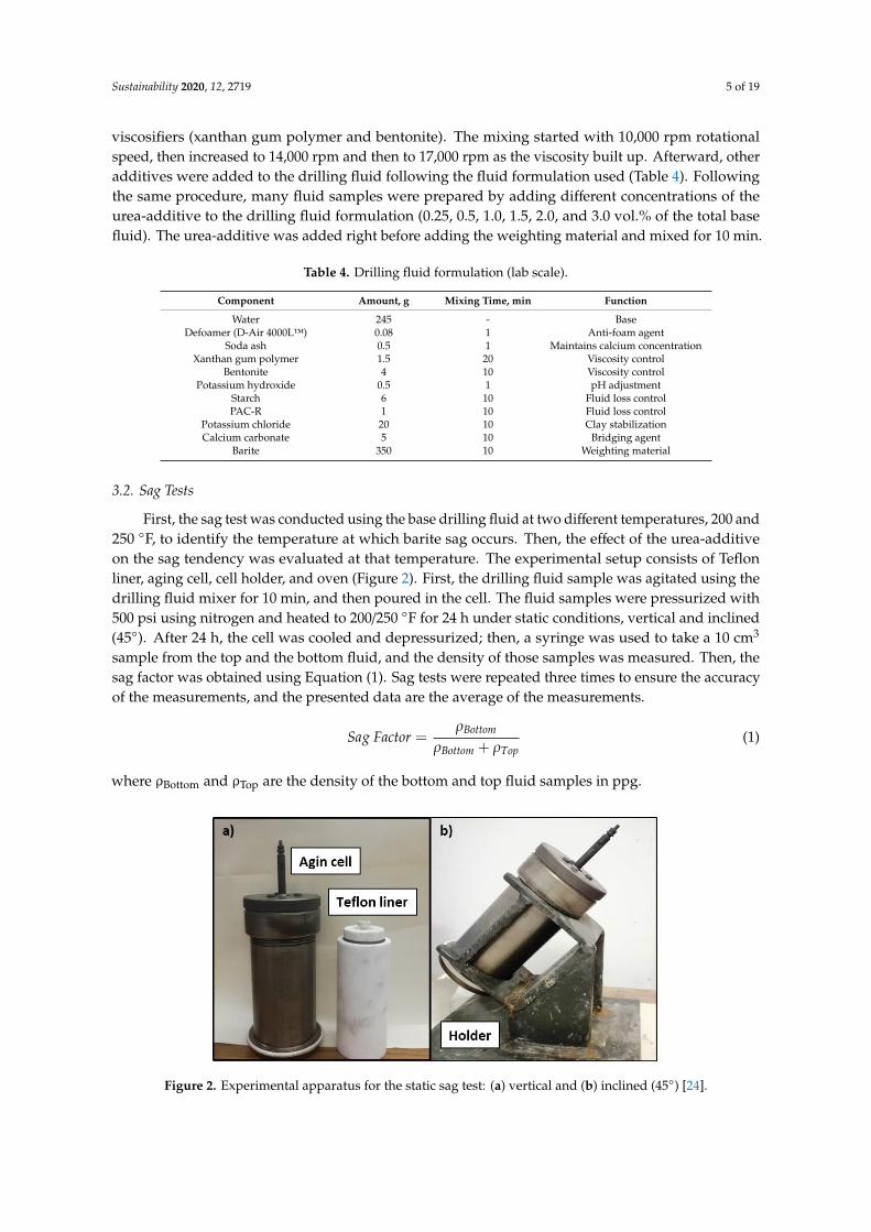
Figure 11 compares the filtration performance curve of the base fluid, 0.5 vol.%, and 1 vol.% drillingfluid samples. It was found that the anti-sagging additive did not affect the filtration performancesignificantly, and the drilling fluid samples had similar filtration performances. The filtrationexperiments were conducted using a ceramic filter disc with uniform porosity and permeability to fairlycompare the results and eliminate the effect of formation heterogeneity [38]. A difference of around 1.4
Sustainability 2020, 12, 2719 11 of 19
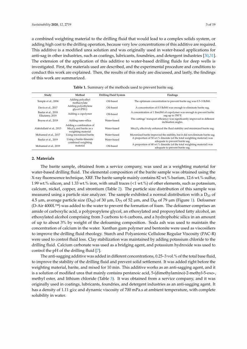
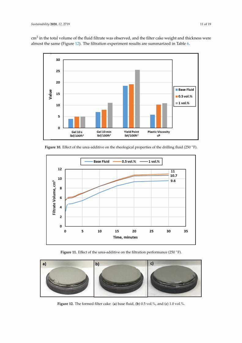
cm3 in the total volume of the fluid filtrate was observed, and the filter cake weight and thickness werealmost the same (Figure 12). The filtration experiment results are summarized in Table 6.
Sustainability 2020, 11, x FOR PEER REVIEW 11 of 21
Figure 10. Effect of the urea-additive on the rheological properties of the drilling fluid (250 °F).
4.3. HPHT Filtration Experiments
Figure 11 compares the filtration performance curve of the base fluid, 0.5 vol.%, and 1 vol.%
drilling fluid samples. It was found that the anti-sagging additive did not affect the filtration
performance significantly, and the drilling fluid samples had similar filtration performances. The
filtration experiments were conducted using a ceramic filter disc with uniform porosity and
permeability to fairly compare the results and eliminate the effect of formation heterogeneity [38]. A
difference of around 1.4 cm3 in the total volume of the fluid filtrate was observed, and the filter cake
weight and thickness were almost the same (Figure 12). The filtration experiment results are
summarized in Table 6.
The anti-sagging additive was proven to be effective in preventing barite sag in aqueous drilling
fluids with the formulation used in this study. However, more research work is needed to determine
the optimum concentration required for different drilling fluid formulations before use in field
operations. Moreover, a lab study should be conducted to evaluate the performance of this additive
at higher solids loading and salt concentrations and ultra-high temperatures.
Figure 10. Effect of the urea-additive on the rheological properties of the drilling fluid (250 ◦F).
Sustainability 2020, 11, x FOR PEER REVIEW 11 of 21
Figure 10. Effect of the urea-additive on the rheological properties of the drilling fluid (250 °F).
4.3. HPHT Filtration Experiments
Figure 11 compares the filtration performance curve of the base fluid, 0.5 vol.%, and 1 vol.%
drilling fluid samples. It was found that the anti-sagging additive did not affect the filtration
performance significantly, and the drilling fluid samples had similar filtration performances. The
filtration experiments were conducted using a ceramic filter disc with uniform porosity and
permeability to fairly compare the results and eliminate the effect of formation heterogeneity [38]. A
difference of around 1.4 cm3 in the total volume of the fluid filtrate was observed, and the filter cake
weight and thickness were almost the same (Figure 12). The filtration experiment results are
summarized in Table 6.
The anti-sagging additive was proven to be effective in preventing barite sag in aqueous drilling
fluids with the formulation used in this study. However, more research work is needed to determine
the optimum concentration required for different drilling fluid formulations before use in field
operations. Moreover, a lab study should be conducted to evaluate the performance of this additive
at higher solids loading and salt concentrations and ultra-high temperatures.
Figure 11. Effect of the urea-additive on the filtration performance (250 ◦F).
Sustainability 2020, 11, x FOR PEER REVIEW 12 of 21
Figure 11. Effect of the urea-additive on the filtration performance (250 °F).
Figure 12. The formed filter cake: a) base fluid, b) 0.5 vol.%, and c) 1.0 vol.%.
Table 6. Summary of filtration experiments.
Parameter Base fluid 0.5 vol.% 1.0 vol.%
Filtrate volume, cm3 9.6 11 10.7
Filter cake weight, g 29.1 34.94 29.77
Filter cake thickness, mm 3.6 4.2 3.6
4.4. Molecular Investigation of Fluid Loss Control Agents
Molecular simulation can be employed to shed some light on the performance of fluid loss
control additives. These polymeric substances tend to accumulate on the surfaces of the wellbore,
creating an impermeable layer to avoid further drilling fluid invasion. In the experimental part, starch
and polyanionic cellulose were used for this purpose. The two polymers were recreated on a
molecular platform, as shown in Figure 13. Polymer Consistent Force Field (PCFF+), which has the
capability of capturing the properties of all the atoms present in the system, is used to define the
intermolecular atom types and charges. Detailed assignments of bonding are given in the first part
of the Appendix. The molecular simulation was then carried out with the objective of forming a thin
polymeric layer in typical reservoir conditions and then characterizing its porosity. The latter serves
as an indicator of how well sealed the formed layer is.
Figure 13. Starch (left) and Polyanionic Cellulose (PAC) (right) recreated for molecular simulation.
Two thin layers of starch and PAC were formed in reservoir conditions of 250 °F and 3000 psi,
as shown in Figure 14. The molecular simulation protocol consisted of initialization with a 9.5 cutoff
value, followed by an constant particle number, volume and temperature (NVT) stage run for 250 ps
and then a series of four NPT stages of 200, 200, 400, and 400 ps, respectively, performed using
LAMPPS open source software assisted by the MedeA interface.
Starch PAC
Figure 12. The formed filter cake: (a) base fluid, (b) 0.5 vol.%, and (c) 1.0 vol.%.
Sustainability 2020, 12, 2719 12 of 19
Table 6. Summary of filtration experiments.
Parameter Base Fluid 0.5 vol.% 1.0 vol.%
Filtrate volume, cm3 9.6 11 10.7Filter cake weight, g 29.1 34.94 29.77
Filter cake thickness, mm 3.6 4.2 3.6
The anti-sagging additive was proven to be effective in preventing barite sag in aqueous drillingfluids with the formulation used in this study. However, more research work is needed to determine theoptimum concentration required for different drilling fluid formulations before use in field operations.Moreover, a lab study should be conducted to evaluate the performance of this additive at highersolids loading and salt concentrations and ultra-high temperatures.
4.4. Molecular Investigation of Fluid Loss Control Agents
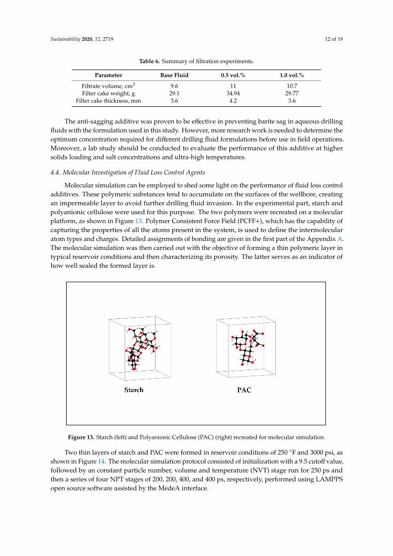
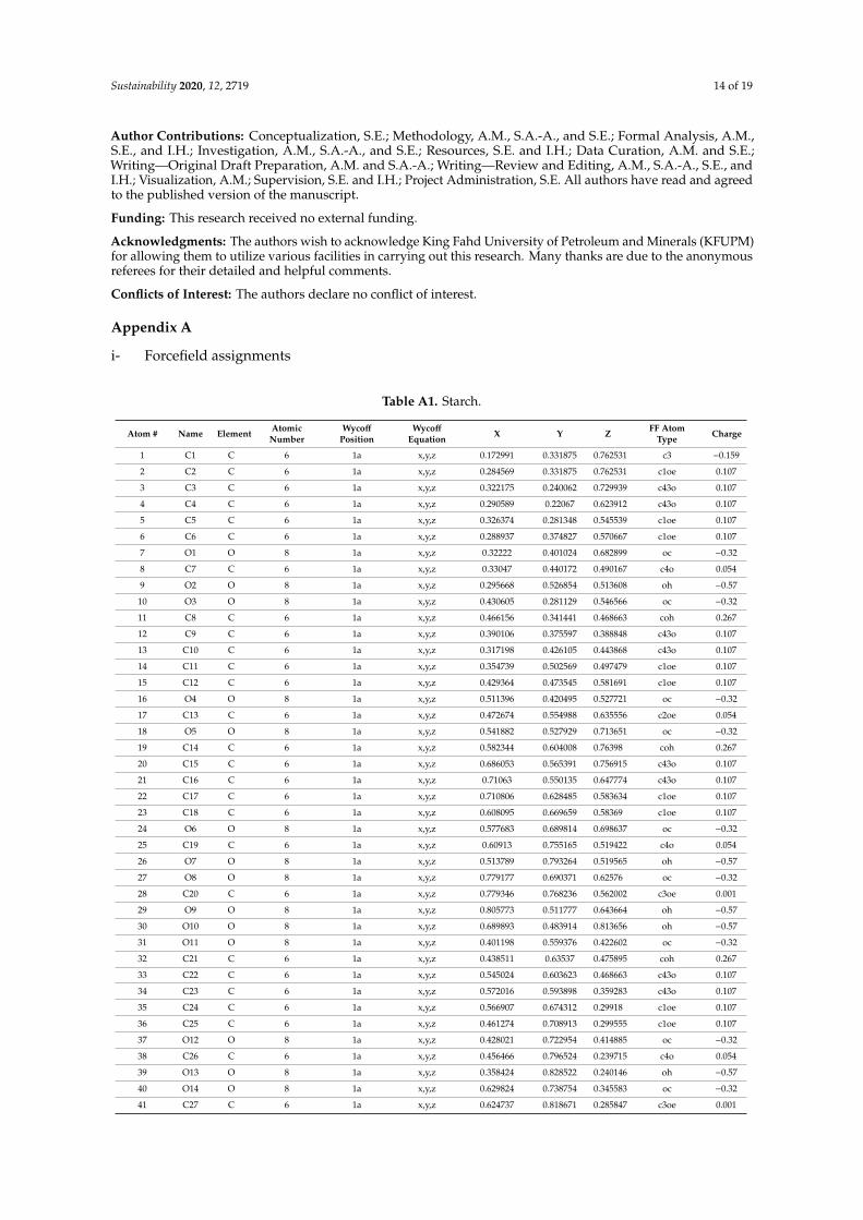
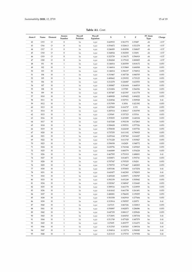
Molecular simulation can be employed to shed some light on the performance of fluid loss controladditives. These polymeric substances tend to accumulate on the surfaces of the wellbore, creatingan impermeable layer to avoid further drilling fluid invasion. In the experimental part, starch andpolyanionic cellulose were used for this purpose. The two polymers were recreated on a molecularplatform, as shown in Figure 13. Polymer Consistent Force Field (PCFF+), which has the capability ofcapturing the properties of all the atoms present in the system, is used to define the intermolecularatom types and charges. Detailed assignments of bonding are given in the first part of the Appendix A.The molecular simulation was then carried out with the objective of forming a thin polymeric layer intypical reservoir conditions and then characterizing its porosity. The latter serves as an indicator ofhow well sealed the formed layer is.
Figure 13. Starch (left) and Polyanionic Cellulose (PAC) (right) recreated for molecular simulation.
Two thin layers of starch and PAC were formed in reservoir conditions of 250 ◦F and 3000 psi, asshown in Figure 14. The molecular simulation protocol consisted of initialization with a 9.5 cutoff value,followed by an constant particle number, volume and temperature (NVT) stage run for 250 ps andthen a series of four NPT stages of 200, 200, 400, and 400 ps, respectively, performed using LAMPPSopen source software assisted by the MedeA interface.

Sustainability 2020, 12, 2719 13 of 19
Figure 14. Two thin layers of (a) starch and (b) PAC formed at 250 ◦F and 3000 psi.
Then, a porosity estimation was carried out using He-pycnometry simulations through theGibbs isotherm module of MedeA. Helium adsorption calculations are given in the Appendix A.The estimated porosity values were around 3% for both cases, indicating that the drilling fluid invasionis minimized when those polymers are employed.
5. Summary and Conclusions
Extensive experimental work was conducted to assess an anti-sagging additive and study itsimpact on the properties of barite-weighted drilling fluid and the barite sag tendency. Based on theresults of this study, the following conclusions are drawn:
1. Adding 0.5–1.0 vol.% of the urea-additive to the base drilling fluid increased the yield pointand gel strength after 10 s at 80 ◦F by around 40–50%. Moreover, the plastic viscosity and gelstrength after 10 min remained almost constant. At 250 ◦F, a 76% drop in the plastic viscosity wasobserved for the base drilling fluid, while the urea-additive reduced that drop to around 50% andmaintained the YP/PV ratio at that temperature.
2. Adding just 0.5–1.0 vol.% of the urea-additive was adequate to enhance the drilling fluid stabilityand prevent barite sag at 250 ◦F. The sag factor was around 0.51 under both vertical andinclined conditions.
3. The urea-additive had no impact on the density and the pH of the drilling fluid, while it hadminimal effect on the filtration performance of the drilling fluids and the properties of the formedfilter cake. The total fluid filtrate increased by around 1.4 cm3, while the filter cake propertieswere almost the same. However, fluid loss control agents such as starch and polyanionic cellulosecan help in minimizing drilling fluid invasions. Molecular simulation of polymeric accumulationsshowed that a thin layer of low porosity is formed under typical reservoir conditions.
4. The developed formulation can be used to drill deep formations efficiently without the barite sagissue at a temperature up to 250 ◦F. Furthermore, the concentration of the urea-additive should beoptimized for different fluid formulations before using it in real field applications. More researchwork is needed to evaluate the performance of this urea-additive at higher solids loading, highsalt concentrations, and ultra-high temperature and pressure. An experimental study is alsoneeded to evaluate the interaction of this additive with formation rocks and fluids and how thismay affect the formation damage.
Sustainability 2020, 12, 2719 14 of 19
Author Contributions: Conceptualization, S.E.; Methodology, A.M., S.A.-A., and S.E.; Formal Analysis, A.M.,S.E., and I.H.; Investigation, A.M., S.A.-A., and S.E.; Resources, S.E. and I.H.; Data Curation, A.M. and S.E.;Writing—Original Draft Preparation, A.M. and S.A.-A.; Writing—Review and Editing, A.M., S.A.-A., S.E., andI.H.; Visualization, A.M.; Supervision, S.E. and I.H.; Project Administration, S.E. All authors have read and agreedto the published version of the manuscript.
Funding: This research received no external funding.
Acknowledgments: The authors wish to acknowledge King Fahd University of Petroleum and Minerals (KFUPM)for allowing them to utilize various facilities in carrying out this research. Many thanks are due to the anonymousreferees for their detailed and helpful comments.
Conflicts of Interest: The authors declare no conflict of interest.
Appendix A
i- Forcefield assignments
Table A1. Starch.
Atom # Name Element AtomicNumber
WycoffPosition
WycoffEquation X Y Z FF Atom
Type Charge
1 C1 C 6 1a x,y,z 0.172991 0.331875 0.762531 c3 −0.159
2 C2 C 6 1a x,y,z 0.284569 0.331875 0.762531 c1oe 0.107
3 C3 C 6 1a x,y,z 0.322175 0.240062 0.729939 c43o 0.107
4 C4 C 6 1a x,y,z 0.290589 0.22067 0.623912 c43o 0.107
5 C5 C 6 1a x,y,z 0.326374 0.281348 0.545539 c1oe 0.107
6 C6 C 6 1a x,y,z 0.288937 0.374827 0.570667 c1oe 0.107
7 O1 O 8 1a x,y,z 0.32222 0.401024 0.682899 oc −0.32
8 C7 C 6 1a x,y,z 0.33047 0.440172 0.490167 c4o 0.054
9 O2 O 8 1a x,y,z 0.295668 0.526854 0.513608 oh −0.57
10 O3 O 8 1a x,y,z 0.430605 0.281129 0.546566 oc −0.32
11 C8 C 6 1a x,y,z 0.466156 0.341441 0.468663 coh 0.267
12 C9 C 6 1a x,y,z 0.390106 0.375597 0.388848 c43o 0.107
13 C10 C 6 1a x,y,z 0.317198 0.426105 0.443868 c43o 0.107
14 C11 C 6 1a x,y,z 0.354739 0.502569 0.497479 c1oe 0.107
15 C12 C 6 1a x,y,z 0.429364 0.473545 0.581691 c1oe 0.107
16 O4 O 8 1a x,y,z 0.511396 0.420495 0.527721 oc −0.32
17 C13 C 6 1a x,y,z 0.472674 0.554988 0.635556 c2oe 0.054
18 O5 O 8 1a x,y,z 0.541882 0.527929 0.713651 oc −0.32
19 C14 C 6 1a x,y,z 0.582344 0.604008 0.76398 coh 0.267
20 C15 C 6 1a x,y,z 0.686053 0.565391 0.756915 c43o 0.107
21 C16 C 6 1a x,y,z 0.71063 0.550135 0.647774 c43o 0.107
22 C17 C 6 1a x,y,z 0.710806 0.628485 0.583634 c1oe 0.107
23 C18 C 6 1a x,y,z 0.608095 0.669659 0.58369 c1oe 0.107
24 O6 O 8 1a x,y,z 0.577683 0.689814 0.698637 oc −0.32
25 C19 C 6 1a x,y,z 0.60913 0.755165 0.519422 c4o 0.054
26 O7 O 8 1a x,y,z 0.513789 0.793264 0.519565 oh −0.57
27 O8 O 8 1a x,y,z 0.779177 0.690371 0.62576 oc −0.32
28 C20 C 6 1a x,y,z 0.779346 0.768236 0.562002 c3oe 0.001
29 O9 O 8 1a x,y,z 0.805773 0.511777 0.643664 oh −0.57
30 O10 O 8 1a x,y,z 0.689893 0.483914 0.813656 oh −0.57
31 O11 O 8 1a x,y,z 0.401198 0.559376 0.422602 oc −0.32
32 C21 C 6 1a x,y,z 0.438511 0.63537 0.475895 coh 0.267
33 C22 C 6 1a x,y,z 0.545024 0.603623 0.468663 c43o 0.107
34 C23 C 6 1a x,y,z 0.572016 0.593898 0.359283 c43o 0.107
35 C24 C 6 1a x,y,z 0.566907 0.674312 0.29918 c1oe 0.107
36 C25 C 6 1a x,y,z 0.461274 0.708913 0.299555 c1oe 0.107
37 O12 O 8 1a x,y,z 0.428021 0.722954 0.414885 oc −0.32
38 C26 C 6 1a x,y,z 0.456466 0.796524 0.239715 c4o 0.054
39 O13 O 8 1a x,y,z 0.358424 0.828522 0.240146 oh −0.57
40 O14 O 8 1a x,y,z 0.629824 0.738754 0.345583 oc −0.32
41 C27 C 6 1a x,y,z 0.624737 0.818671 0.285847 c3oe 0.001
Sustainability 2020, 12, 2719 15 of 19
Table A1. Cont.
Atom # Name Element AtomicNumber
WycoffPosition
WycoffEquation X Y Z FF Atom
Type Charge
42 O15 O 8 1a x,y,z 0.669933 0.561773 0.35487 oh −0.57
43 O16 O 8 1a x,y,z 0.554472 0.520613 0.521278 oh −0.57
44 O17 O 8 1a x,y,z 0.246009 0.454598 0.368657 oh −0.57
45 O18 O 8 1a x,y,z 0.344924 0.302505 0.33691 oh −0.57
46 O19 O 8 1a x,y,z 0.323739 0.134175 0.596919 oh −0.57
47 O20 O 8 1a x,y,z 0.284268 0.175102 0.800825 oh −0.57
48 H1 H 1 1a x,y,z 0.146814 0.283559 0.818172 hc 0.053
49 H2 H 1 1a x,y,z 0.146814 0.315869 0.684508 hc 0.053
50 H3 H 1 1a x,y,z 0.146814 0.396197 0.784912 hc 0.053
51 H4 H 1 1a x,y,z 0.310467 0.347728 0.840705 hc 0.053
52 H5 H 1 1a x,y,z 0.400662 0.239352 0.733125 hc 0.053
53 H6 H 1 1a x,y,z 0.212278 0.226087 0.623553 hc 0.053
54 H7 H 1 1a x,y,z 0.300807 0.261604 0.468519 hc 0.053
55 H8 H 1 1a x,y,z 0.210494 0.37589 0.566526 hc 0.053
56 H9 H 1 1a x,y,z 0.307487 0.421597 0.411778 hc 0.053
57 H10 H 1 1a x,y,z 0.408928 0.439422 0.494222 hc 0.053
58 H11 H 1 1a x,y,z 0.224544 0.527531 0.509928 ho 0.41
59 H12 H 1 1a x,y,z 0.517959 0.3054 0.421392 hc 0.053
60 H13 H 1 1a x,y,z 0.425569 0.416737 0.331 hc 0.053
61 H14 H 1 1a x,y,z 0.287014 0.383617 0.503795 hc 0.053
62 H15 H 1 1a x,y,z 0.29569 0.537323 0.53516 hc 0.053
63 H16 H 1 1a x,y,z 0.393835 0.433089 0.640184 hc 0.053
64 H17 H 1 1a x,y,z 0.415248 0.592158 0.672863 hc 0.053
65 H18 H 1 1a x,y,z 0.508438 0.595531 0.577326 hc 0.053
66 H19 H 1 1a x,y,z 0.550038 0.624349 0.837726 hc 0.053
67 H20 H 1 1a x,y,z 0.737255 0.611192 0.790925 hc 0.053
68 H21 H 1 1a x,y,z 0.655164 0.507369 0.616027 hc 0.053
69 H22 H 1 1a x,y,z 0.731228 0.611743 0.503827 hc 0.053
70 H23 H 1 1a x,y,z 0.556938 0.62429 0.548772 hc 0.053
71 H24 H 1 1a x,y,z 0.630756 0.741044 0.439265 hc 0.053
72 H25 H 1 1a x,y,z 0.660089 0.800779 0.554228 hc 0.053
73 H26 H 1 1a x,y,z 0.467595 0.751919 0.488001 ho 0.41
74 H27 H 1 1a x,y,z 0.830871 0.814873 0.593741 hc 0.053
75 H28 H 1 1a x,y,z 0.707547 0.797035 0.56201 hc 0.053
76 H29 H 1 1a x,y,z 0.799753 0.751467 0.482203 hc 0.053
77 H30 H 1 1a x,y,z 0.853186 0.553003 0.673254 ho 0.41
78 H31 H 1 1a x,y,z 0.643477 0.442383 0.782833 ho 0.41
79 H32 H 1 1a x,y,z 0.405228 0.650971 0.550787 hc 0.053
80 H33 H 1 1a x,y,z 0.592159 0.651249 0.505842 hc 0.053
81 H34 H 1 1a x,y,z 0.520367 0.548947 0.324445 hc 0.053
82 H35 H 1 1a x,y,z 0.589516 0.661778 0.218959 hc 0.053
83 H36 H 1 1a x,y,z 0.414162 0.661758 0.261491 hc 0.053
84 H37 H 1 1a x,y,z 0.480081 0.786692 0.159295 hc 0.053
85 H38 H 1 1a x,y,z 0.503358 0.843918 0.277684 hc 0.053
86 H39 H 1 1a x,y,z 0.315914 0.785557 0.20573 ho 0.41
87 H40 H 1 1a x,y,z 0.67215 0.867226 0.320813 hc 0.053
88 H41 H 1 1a x,y,z 0.550897 0.842875 0.286086 hc 0.053
89 H42 H 1 1a x,y,z 0.647339 0.806117 0.205626 hc 0.053
90 H43 H 1 1a x,y,z 0.713691 0.604765 0.387334 ho 0.41
91 H44 H 1 1a x,y,z 0.511749 0.477428 0.487579 ho 0.41
92 H45 H 1 1a x,y,z 0.27695 0.492777 0.316273 ho 0.41
93 H46 H 1 1a x,y,z 0.312765 0.265203 0.389334 ho 0.41
94 H47 H 1 1a x,y,z 0.394914 0.132774 0.598385 ho 0.41
95 H48 H 1 1a x,y,z 0.213115 0.175733 0.797958 ho 0.41

Sustainability 2020, 12, 2719 16 of 19
Table A2. PAC.
Atom # Name Element Atomicnumber
WycoffPosition
WycoffEquation X Y Z FF Atom
Type Charge
1 C1 C 6 1a x,y,z 0.513163 0.722667 0.454071 c2oe 0.054
2 C2 C 6 1a x,y,z 0.478942 0.669498 0.605049 c1oe 0.107
3 C3 C 6 1a x,y,z 0.373177 0.710624 0.663953 c43o 0.107
4 C4 C 6 1a x,y,z 0.285433 0.686912 0.550835 c43o 0.107
5 C5 C 6 1a x,y,z 0.283075 0.577245 0.523724 c43o 0.107
6 C6 C 6 1a x,y,z 0.38819 0.547862 0.463682 coh 0.267
7 O1 O 8 1a x,y,z 0.467066 0.56636 0.577042 oc −0.32
8 O2 O 8 1a x,y,z 0.392212 0.445572 0.43524 oc −0.32
9 C7 C 6 1a x,y,z 0.502271 0.422312 0.406015 c1oe 0.107
10 C8 C 6 1a x,y,z 0.568449 0.421539 0.558158 c1oe 0.107
11 O3 O 8 1a x,y,z 0.533879 0.340712 0.666164 oc −0.32
12 C9 C 6 1a x,y,z 0.521445 0.242076 0.587262 coh 0.267
13 C10 C 6 1a x,y,z 0.455082 0.250801 0.441974 c43o 0.107
14 C11 C 6 1a x,y,z 0.505278 0.322628 0.332261 c43o 0.107
15 O4 O 8 1a x,y,z 0.613752 0.292302 0.295536 oh −0.57
16 O5 O 8 1a x,y,z 0.446687 0.152222 0.369569 oh −0.57
17 O6 O 8 1a x,y,z 0.625578 0.202517 0.54618 oh −0.57
18 C12 C 6 1a x,y,z 0.566382 0.523731 0.651178 c2oe 0.054
19 O7 O 8 1a x,y,z 0.582028 0.613623 0.546866 oc −0.32
20 O8 O 8 1a x,y,z 0.26166 0.524457 0.670148 oh −0.57
21 O9 O 8 1a x,y,z 0.183688 0.720195 0.613857 oh −0.57
22 O10 O 8 1a x,y,z 0.380345 0.818516 0.687913 oh −0.57
23 O11 O 8 1a x,y,z 0.616691 0.682099 0.380761 oc −0.32
24 H1 H 1 1a x,y,z 0.523351 0.799982 0.478606 hc 0.053
25 H2 H 1 1a x,y,z 0.451408 0.714894 0.370873 hc 0.053
26 H3 H 1 1a x,y,z 0.535598 0.678615 0.693189 hc 0.053
27 H4 H 1 1a x,y,z 0.355306 0.676198 0.772583 hc 0.053
28 H5 H 1 1a x,y,z 0.300047 0.723987 0.443468 hc 0.053
29 H6 H 1 1a x,y,z 0.223789 0.559367 0.440251 hc 0.053
30 H7 H 1 1a x,y,z 0.405584 0.587928 0.359924 hc 0.053
31 H8 H 1 1a x,y,z 0.534372 0.476054 0.327749 hc 0.053
32 H9 H 1 1a x,y,z 0.648517 0.40696 0.526661 hc 0.053
33 H10 H 1 1a x,y,z 0.483557 0.191738 0.665519 hc 0.053
34 H11 H 1 1a x,y,z 0.378091 0.276975 0.472049 hc 0.053
35 H12 H 1 1a x,y,z 0.460398 0.324803 0.227417 hc 0.053
36 H13 H 1 1a x,y,z 0.657829 0.291458 0.395134 ho 0.41
37 H14 H 1 1a x,y,z 0.502216 0.14579 0.283557 ho 0.41
38 H15 H 1 1a x,y,z 0.680625 0.257874 0.554148 ho 0.41
39 H16 H 1 1a x,y,z 0.629792 0.522485 0.732915 hc 0.053
40 H17 H 1 1a x,y,z 0.493954 0.529905 0.714596 hc 0.053
41 H19 H 1 1a x,y,z 0.300236 0.559503 0.759677 ho 0.41
42 H20 H 1 1a x,y,z 0.154476 0.666592 0.687862 ho 0.41
43 H21 H 1 1a x,y,z 0.372035 0.85421 0.58293 ho 0.41
44 C13 C 6 1a x,y,z 0.638785 0.699253 0.631155 c2oe 0.054
45 C14 C 6 1a x,y,z 0.721705 0.746325 0.527925 c_1 0.003
46 O12 O 8 1a x,y,z 0.693674 0.789124 0.393837 o- 0
47 O13 O 8 1a x,y,z 0.833075 0.745494 0.575186 o −0.003
48 C15 C 6 1a x,y,z 0.683434 0.618188 0.484962 c2oe 0.054
49 C16 C 6 1a x,y,z 0.767156 0.540745 0.453012 c_1 0.003
50 O14 O 8 1a x,y,z 0.7701 0.494722 0.315753 o- 0
51 O15 O 8 1a x,y,z 0.845524 0.516138 0.572953 o −0.003
52 H22 H 1 1a x,y,z 0.744033 0.66319 0.435863 hc 0.053
53 H23 H 1 1a x,y,z 0.636373 0.560931 0.432774 hc 0.053
54 H24 H 1 1a x,y,z 0.675385 0.671506 0.733834 hc 0.053
55 H25 H 1 1a x,y,z 0.58324 0.756603 0.661779 hc 0.053

Sustainability 2020, 12, 2719 17 of 19
ii- He-Pycnometry CalculationsNm = Na
− ρaVP
where Nm and Na are the number of excess and adsorbed molecules of helium, respectively. VPis the pore volume, and ρa is the density of helium. Under the assumption of zero excess ofmolecules at such a degree of confinement, the above equation can be used to estimate the porevolume. Then, porosity can be calculated when VP is divided by the bulk volume. A summary ofthe calculations is given below:
Table A3. Summary of the calculations.
Pressure(bar)
Density(g/mL)
MolecularVolume
(Å3/molecule)
Starch(molecule/box)
PAC(molecule/box)
VP starch(A3)
VP PAC(A3) ϕ Starch ϕ PAC
0.1 1.62 × 10⁻⁵ 411000.0 4.87 × 10⁻⁴ 3.49 × 10⁻⁴ 200.2 143.4 0.029 0.032
0.2 3.23 × 10⁻⁵ 206000.0 1.00 × 10⁻³ 6.91 × 10⁻⁴ 206.0 142.3 0.030 0.032
0.3 4.85 × 10⁻⁵ 137000.0 1.58 × 10⁻³ 1.09 × 10⁻³ 216.9 149.6 0.032 0.034
0.4 6.46 × 10⁻⁵ 103000.0 2.11 × 10⁻³ 1.44 × 10⁻³ 216.9 148.4 0.032 0.033
0.5 8.08 × 10⁻⁵ 82300.0 2.54 × 10⁻³ 1.78 × 10⁻³ 209.0 146.5 0.031 0.033
0.6 9.69 × 10⁻⁵ 68600.0 3.02 × 10⁻³ 2.17 × 10⁻³ 207.2 148.9 0.030 0.033
0.7 1.13 × 10⁻⁴ 58800.0 3.64 × 10⁻³ 2.50 × 10⁻³ 214.0 147.0 0.031 0.033
0.8 1.29 × 10⁻⁴ 51400.0 4.09 × 10⁻³ 2.74 × 10⁻³ 210.2 140.8 0.031 0.032
0.9 1.45 × 10⁻⁴ 45700.0 4.52 × 10⁻³ 3.21 × 10⁻³ 206.6 146.7 0.030 0.033
1 1.61 × 10⁻⁴ 41200.0 5.02 × 10⁻³ 3.53 × 10⁻³ 206.8 145.4 0.030 0.033
References
1. Bourgoyne, A.T.; Chenevert, M.E.; Millheim Keith, K.; Young, F.S. Applied Drilling Engineering; Society ofPetroleum Engineers: Richardson, TX, USA, 1986; Chapter 2; p. 514. ISBN 9781555630010.
2. Hossain, M.E.; Al-Majed, A.A. Fundamentals of Sustainable Drilling Engineering; Scrivener Publishing LLC:Beverly, MA, USA, 2015; ISBN 9780470878170.
3. Sloan, J.P.; Brooks, J.P.; Dear, S.F., III. A New, Nondamaging, Acid-Soluble Weighting Material. J. Pet. Technol.1975, 27, 15–20. [CrossRef]
4. Tuntland, O.B.; Herfjord, H.J.; Lehne, K.A.; Haaland, E. Iron oxide as Weight Materials for Drilling Muds.Erdoel-Erdgas Z. 1981, 97, 300–302. Available online: https://www.osti.gov/etdeweb/biblio/5832121 (accessedon 20 January 2020).
5. Walker, C.O. Alternative Weighting Material. J. Pet. Technol. 1983, 35, 2158–2164. [CrossRef]6. Al-Yami, A.S.; Nasr-El-Din, H.A. An Innovative Manganese Tetra-Oxide/KCl Water-Based Drill-in Fluids for
HT/HP Wells. In Proceedings of the SPE Annual Technical Conference and Exhibition, Anaheim, CA, USA,11–14 November 2007. SPE-110638. [CrossRef]
7. Caenn, R.; Darley, H.C.H.; Gray, G.R. Composition and Properties of Drilling and Completion Fluids, 6th ed.;Gulf Professional Publishing: Houston, TX, USA; The Boulevard: Oxford, UK, 2011; Chapter 11; p. 535.ISBN 9780123838582.
8. Al-Bagoury, M.; Steele, C.D. A New, Alternative Weight Material for Drilling Fluids. In Proceedings ofthe IADC/SPE Drilling Conference and Exhibition, San Diego, CA, USA, 6–8 March 2012. SPE-151331-MS.[CrossRef]
9. Xiao, J.; Nasr-El-Din, H.A.; Al-Bagoury, M. Evaluation of Micronized Ilmenite as a Weighting Material inOil-based Drilling Fluids for HPHT Applications. In Proceedings of the SPE European Formation DamageConference and Exhibition, Noordwijk, The Netherlands, 5–7 June 2013. SPE-165184-MS. [CrossRef]
10. Tehrani, A.; Cliffe, A.; Hodder, M.H.; Young, S.; Lee, J.; Stark, J.; Seale, S. Alternative Drilling Fluid WeightingAgents: A Comprehensive Study on Ilmenite and Hematite. In Proceedings of the IADC/SPE DrillingConference and Exhibition, Fort Worth, TX, USA, 4–6 March 2014. SPE-167937-MS. [CrossRef]
11. Nguyen, T.; Miska, S.; Yu, M.; Takach, N. Predicting Dynamic Barite Sag in Newtonian-Oil Based DrillingFluids in Pipe. In Proceedings of the SPE Annual Technical Conference and Exhibition, New Orleans, LA,USA, 4–7 October 2009. SPE-124137-MS. [CrossRef]
Sustainability 2020, 12, 2719 18 of 19
12. Ba Geri, B.S.; Mahmoud, M.A.; Abdulraheem, A.; Al-Mutairi, S.H.; Shawabkeh, R.A. Single stage filter cakeremoval of barite weighted water based drilling fluid. J. Pet. Sci. Eng. 2016, 149, 476–484. [CrossRef]
13. Mohamed, A.K.; Elkatatny, S.A.; Mahmoud, M.A.; Shawabkeh, R.A.; Al-Majed, A.A. The Evaluation ofMicronized Barite as a Weighting Material for Completing HPHT Wells. In Proceedings of the SPE MiddleEast Oil & Gas Show and Conference, Manama, Bahrain, 6–9 March 2017. SPE183768-MS. [CrossRef]
14. Moajil, A.M.; Nasr-El-Din, H.A. Formation Damage Caused by Improper Mn3O4-based Filter Cake CleanupTreatments. In Proceedings of the SPE European Formation Damage Conference, Noordwijk, The Netherlands,7–10 June 2011. SPE-144179-MS. [CrossRef]
15. Al-Yami, A.S.; Nasr-El-Din, H.A.; Al-Shafei, M.A.; Bataweel, M.A. Impact of Water-Based Drilling-In Fluidson Solids Invasion and Damage Characteristics. Spe Prod. Oper. 2013, 25, 40–49. [CrossRef]
16. Bern, P.A.; Oort, E.V.; Neustadt, B.; Ebeltoft, H.; Zurdo, C.; Zamora, M.; Slater, K.S. Barite Sag: Measurement,Modeling, and Management. Spe Drill. Completion 2000, 15, 25–30. [CrossRef]
17. Omland, T.H.; Saasen, A.; Zwaag, C.; Amundsen, P.A. The Effect of Weighting Material Sag on DrillingOperation Efficiency. In Proceedings of the SPE Asia Pacific Oil & Gas Conference and Exhibition, Jakarta,Indonesia, 30 October–1 November 2007. SPE-110537-MS. [CrossRef]
18. Hanson, P.M.; Trigg, T.K.; Rachal, G.; Zamora, M. Investigation of Barite “Sag” in Weighted Drilling Fluids inHighly Deviated Wells. In Proceedings of the 65th Annual Technical Conference and Exhibition, New Orleans,LA, USA, 23–26 September 1990. Paper SPE-20423-MS. [CrossRef]
19. Scott, P.D.; Zamora, M.; Aldea, C. Barite-Sag Management: Challenges, Strategies, Opportunities.In Proceedings of the IADC/SPE Drilling Conference, Dallas, TX, USA, 2–4 March 2004. SPE-87136-MS.[CrossRef]
20. Saasen, A.; Jordal, O.H.; Burkhead, D.; Berg, P.C.; Løklingholm, G.; Pedersen, E.S.; Turner, J.; Harris, M.J.Drilling HT/HP Wells Using a Cesium Formate Based Drilling Fluid. In Proceedings of the IADC/SPEDrilling Conference, Dallas, TX, USA, 26–28 February 2002. SPE-74541-MS. [CrossRef]
21. Temple, C.; Paterson, F.; Leith, D. Method for Reducing Sag in Drilling, Completion, and Workover Fluids.WO Patent WO 2004/113467A1, 29 December 2004.
22. Davis, C.; Livanec, P.; Shumway, W. Additive to Enhance Sag Stability of Drilling Fluid. WO Patent WO2017/188946 A1, 2 November 2017.
23. Basfar, S.; Elkatatny, S.; Mahmoud, M.; Kamal, M.S.; Murtaza, M.; Stanitzek, T. Prevention of Barite Saggingwhile Drilling High-Pressure High-Temperature (HPHT) Wells. In Proceedings of the SPE Kingdom ofSaudi Arabia Annual Technical Symposium and Exhibition, Dammam, Saudi Arabia, 23–26 April 2018.SPE-192198-MS. [CrossRef]
24. Elkatatny, S.M. Enhancing the Stability of Invert Emulsion Drilling Fluid for Drilling in High-PressureHigh-Temperature Conditions. Energies 2018, 11, 2393. [CrossRef]
25. Boyou, N.V.; Ismail, I.; Wan Sulaiman, W.R.; Sharifi, H.A.; Husein, N.; Hui, H.T.; Nadaraja, K. Experimentalinvestigation of hole cleaning in directional drilling by using nano-enhanced water-based drilling fluids.J. Pet. Sci. Eng. 2019, 176, 220–231. [CrossRef]
26. Alabdullatif, Z.; Al-Yami, A.; Wagle, V.; Bubshait, A.; Al-Safran, A. Development of New Kill Fluids withMinimum Sagging Problems for High-Pressure Jilh Formation in Saudi Arabia. Saudi Aramco J. Technol. 2015.[CrossRef]
27. Basfar, S.; Mohamed, A.; Elkatatny, S.; Al-Majed, A. A combined barite-ilmenite weighting material toprevent barite sag in water-based drilling fluid. Materials 2019, 12, 1945. [CrossRef] [PubMed]
28. Mohamed, A.; Basfar, S.; Elkatatny, S.; Al-Majed, M. Prevention of Barite Sag in Oil-Based Drilling FluidsUsing a Mixture of Barite and Ilmenite as Weighting Material. Sustainability 2019, 11, 5617. [CrossRef]
29. Mahmoud, M.A.; Al-Mutairi, S.H.; Abdulraheem, A. Effect of Sand Content on the Filter Cake Properties andRemoval During Drilling Maximum Reservoir Contact Wells in Sandstone Reservoir. J. Energy Resour. Technol.2016, 138, 32901. [CrossRef]
30. Nagelsdiek, R.; Buhne, S.; Gaul, S.; Jacobs, B.; Karwath, V. Urea-Group- and/or Urethane Group-ContainingAmides as and in Rheology Control Agents, Their Preparation and Their Use. WO Patent WO 2018/138236A1,2 August 2018.
31. Karlheinz, H.; Ulrich, O.; Axel, W.; Heribert, H.; Christoph, B. Rheologically Active Urea UrethaneCompounds. U.S. Patent US6617468B2, 22 September 2002.

Sustainability 2020, 12, 2719 19 of 19
32. Maxey, J. Rheological Analysis of Static and Dynamic Sag in Drilling Fluids. Annu. Trans. Nord. Rheol. Soc.2007, 15, 181.
33. Skalle, P.; Backe, K.R.; Lyomov, S.K.; Sveen, J. Barite Segregation in Inclined Boreholes. J. Can. Pet. Technol.1999, 38. [CrossRef]
34. Lahalih, S.M.; Dairanieh, I.S. Development of novel polymeric drilling mud dispersants. Eur. Polym. J. 1988,25, 187–192. [CrossRef]
35. Power, D.; Zamora, M. Drilling Fluid Yield Stress: Measurement Techniques for Improved Understanding ofCritical Drilling Fluid Parameters. In Proceedings of the AADE National Technology Conference, Houston,TX, USA, 1–3 April 2003. AADE-03-NTCE-35.
36. Chilingarian, G.; Alp, E.; Uslu, S.; Gonzales, S.; Ronald, J. Drilling Fluid Evaluation Using Yield Point-PlasticViscosity Correlation; Paper SPE 12469; Society of Petroleum Engineers: Richardson, TX, USA, 27 July 1983.
37. Wang, Z.; Bai, Y.; Zhang, H.; Liu, Y. Investigation on gelation nucleation kinetics of waxy crude oil emulsionsby their thermal behavior. J. Pet. Sci. Eng. 2019, 181, 106230. [CrossRef]
38. Rui, Z.; Guo, T.; Feng, Q.; Qu, Z.; Qi, N.; Gong, F. Influence of gravel on the propagation pattern of hydraulicfracture in the glutenite reservoir. J. Pet. Sci. Eng. 2018, 165, 627–639. [CrossRef]
© 2020 by the authors. Licensee MDPI, Basel, Switzerland. This article is an open accessarticle distributed under the terms and conditions of the Creative Commons Attribution(CC BY) license (http://creativecommons.org/licenses/by/4.0/).