preventing cryptographic key leakage in cloud virtual machines€¦ · the csps use virtual machine...
TRANSCRIPT
This paper is included in the Proceedings of the 23rd USENIX Security Symposium.
August 20–22, 2014 • San Diego, CA
ISBN 978-1-931971-15-7
Open access to the Proceedings of the 23rd USENIX Security Symposium
is sponsored by USENIX
Preventing Cryptographic Key Leakage in Cloud Virtual Machines
Erman Pattuk, Murat Kantarcioglu, Zhiqiang Lin, and Huseyin Ulusoy, The University of Texas at Dallas
https://www.usenix.org/conference/usenixsecurity14/technical-sessions/presentation/pattuk
USENIX Association 23rd USENIX Security Symposium 703
Preventing Cryptographic Key Leakage in Cloud Virtual Machines
Erman Pattuk, Murat Kantarcioglu, Zhiqiang Lin, Huseyin UlusoyThe University of Texas at Dallas
800 W. Campbell Rd, Richardson TX, 75080
AbstractIn a typical infrastructure-as-a-service cloud setting,
different clients harness the cloud provider’s services byexecuting virtual machines (VM). However, recent studieshave shown that the cryptographic keys, the most crucialcomponent in many of our daily used cryptographic pro-tocols (e.g., SSL/TLS), can be extracted using cross-VMside-channel attacks. To defeat such a threat, this paperintroduces HERMES, a new system that aims to protectthe cryptographic keys in the cloud against any kind ofcross-VM side-channel attacks by simply partitioning thecryptographic keys into random shares, and storing eachshare in a different VM. Moreover, it also periodicallyre-shares the cryptographic keys, thereby invalidating thepotentially extracted partial ones. We have implementedHERMES as a library extension that is transparent to theapplication software, and performed deep case studieswith a web and a mail server on Amazon EC2 cloud. Ourexperimental results show that the runtime overhead ofthe proposed system can be as low as 1%.
1 Introduction
Recent advances in cloud computing enable customersto outsource their computing tasks to the cloud ser-vice providers (CSPs). Typically, CSPs manage exten-sive amount of computational resources, and provideservices, such as Infrastructure-as-a-service (IaaS) [40],Platform-as-a-service (PaaS) [31], Software-as-a-service(SaaS) [44]. By outsourcing core computing to the cloud,customers can mitigate the burden of resource manage-ment, and concentrate more on the core business tasks. Arecent study on the cloud usage [3] reported that nearly30% of enterprise IT organizations use public IaaS, suchas Microsoft’s Azure Service [12], Amazon’s Elastic Com-pute Cloud (EC2) [4], or Google’s Compute Engine [9].
Despite its numerous advantages, cloud computing alsointroduces new challenges and concerns, primarily the se-curity and privacy risks [48]. The concerns simply stem
from outsourcing critical data (e.g., health records, socialsecurity numbers, or even cryptographic keys) and/or com-puting capabilities to a distant computing environment,where the resources are shared with other potentially un-trusted customers.
In particular, to increase efficiency and reduce costs,a CSP may place multiple virtual machines (VMs), be-longing to different customers, to the same physical ma-chine. In such an execution platform, VMs should belogically isolated from each other to protect the privacyof each client. The CSPs use virtual machine monitors(VMM) to realize logical isolation among VMs runningon the same physical machine. However, recent studiesshow that a clever adversary can perform cross-VM side-channel attacks (for brevity, cross-VM attack) to learnprivate information that resides in another VM, even un-der carefully enforced logical isolation in public cloudinfrastructures. More specifically, Ristenpart et al. [41]showed heuristics to improve an adversary’s capabilitiesto place its VMs alongside the victim VMs, and learncrude information (e.g., aggregate cache usage). Mostrecently, Zhang et al. [51] managed to extract ElGamaldecryption keys by cross-VM attacks. These studies haveclearly demonstrated that logical isolation and trustworthycloud provider are not necessarily enough to guaranteethe security of sensitive information.
It would be too optimistic to assume that an adversaryis only limited to the two aforementioned attacks. Un-fortunately, there exists a wide variety of side-channelattacks, each with its own setup and methodology (e.g.,[13–15, 19, 26, 28, 34, 43]). Simply, the absence of suchattacks on public cloud infrastructures does not neces-sarily mean that they are inapplicable. In fact, there areside-channel attacks that target virtualized environments,and leverage timings of cryptographic operations or mon-itoring of common resource usage [39, 47]. Those attacksmay be just one step behind being directly applicable tothe public cloud setting; which is why proposing preven-tion mechanisms is extremely vital for the security and
704 23rd USENIX Security Symposium USENIX Association
privacy of the sensitive data in the VMs including thecryptographic keys.
To this end, we present HERMES, a system that reme-dies the cryptographic key disclosure vulnerabilities ofVMs in the public cloud by using well-established crypto-graphic tools such as Secret Sharing and Threshold Cryp-tography. Specifically, the key technique in our system isto partition a cryptographic key into several pieces, whichare computed using threshold cryptosystems, and to storeeach share on a different VM. This makes it harder foran adversary to capture the complete cryptographic keyitself, since it now has to extract shares from multipleVMs (note that there is no single key or a centralized keyanymore in HERMES). To further improve the resilience,the same cryptographic key is re-shared periodically, suchthat a share is meaningful in only one time period. Conse-quently, we introduce two significant challenges againsta successful attack: (i) multiple VMs should be attacked,and (ii) each attack should succeed within a certain timeperiod. As a proof-of-concept, we apply HERMES to pro-tect the cryptographic keys of Secure Sockets Layer (SSL)and Transport Layer Security (TLS) protocols.
Contributions. In short, this paper makes the followingfour contributions:
1. We present HERMES, a novel system to prevent theleakage of cryptographic keys in cloud VMs viamathematically proven techniques – Secret Sharingand Threshold Cryptography.
2. As a proof-of-concept, we build a prototype of HER-MES and apply it to protect the SSL/TLS crypto-graphic keys, which is significantly more resilient toany cross-VM attack.
3. We empirically evaluate HERMES with micro bench-marks, and case studies for a web server and a mailserver, and show that with optimal setup, HERMEScan operate with overheads as low as 1%.
4. We formalize the problem of finding good HERMESconfigurations, which minimizes the security risk forgiven monetary and performance constraints.
Organization. The rest of the paper is structured as fol-lows: We start by providing some background informationin §2 about the protocols and techniques used in HERMES.It is followed by the threat model in §3, and the full techni-cal details of HERMES in §4. Then, we evaluate HERMESregarding its efficiency in §5, and discuss its security in §6.Finally, we review the related work in §7, and concludein §8.
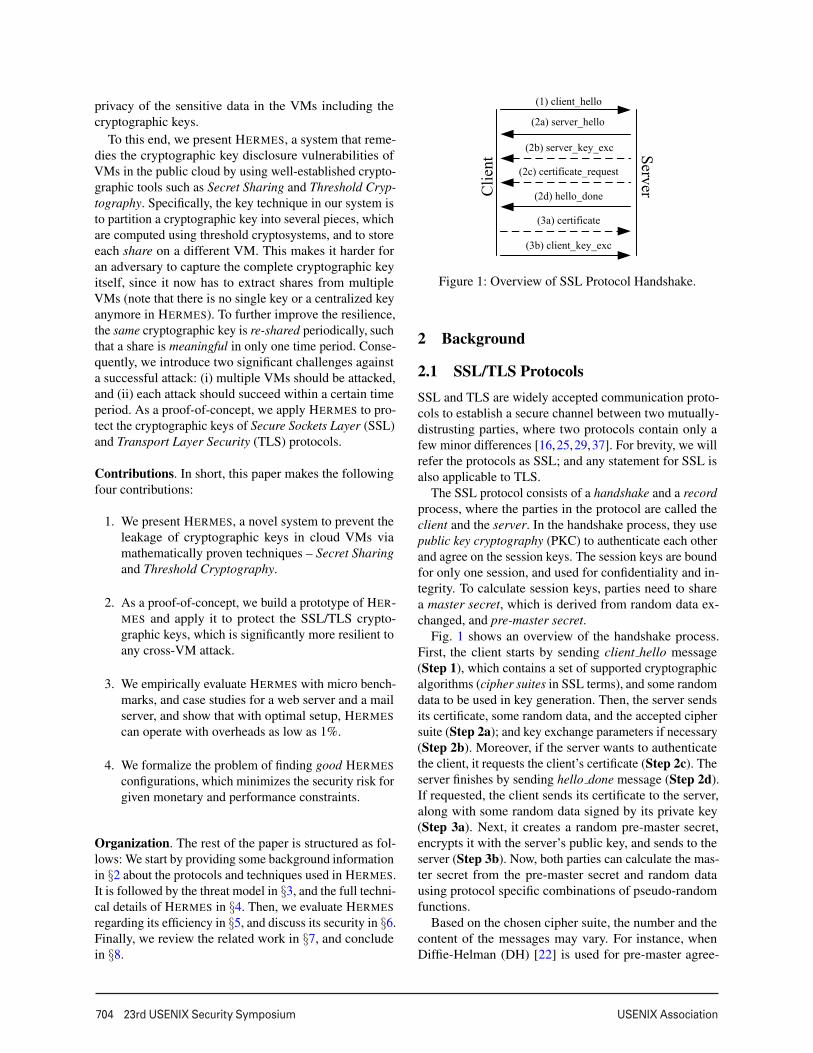
Figure 1: Overview of SSL Protocol Handshake.
2 Background
2.1 SSL/TLS ProtocolsSSL and TLS are widely accepted communication proto-cols to establish a secure channel between two mutually-distrusting parties, where two protocols contain only afew minor differences [16,25,29,37]. For brevity, we willrefer the protocols as SSL; and any statement for SSL isalso applicable to TLS.
The SSL protocol consists of a handshake and a recordprocess, where the parties in the protocol are called theclient and the server. In the handshake process, they usepublic key cryptography (PKC) to authenticate each otherand agree on the session keys. The session keys are boundfor only one session, and used for confidentiality and in-tegrity. To calculate session keys, parties need to sharea master secret, which is derived from random data ex-changed, and pre-master secret.
Fig. 1 shows an overview of the handshake process.First, the client starts by sending client hello message(Step 1), which contains a set of supported cryptographicalgorithms (cipher suites in SSL terms), and some randomdata to be used in key generation. Then, the server sendsits certificate, some random data, and the accepted ciphersuite (Step 2a); and key exchange parameters if necessary(Step 2b). Moreover, if the server wants to authenticatethe client, it requests the client’s certificate (Step 2c). Theserver finishes by sending hello done message (Step 2d).If requested, the client sends its certificate to the server,along with some random data signed by its private key(Step 3a). Next, it creates a random pre-master secret,encrypts it with the server’s public key, and sends to theserver (Step 3b). Now, both parties can calculate the mas-ter secret from the pre-master secret and random datausing protocol specific combinations of pseudo-randomfunctions.
Based on the chosen cipher suite, the number and thecontent of the messages may vary. For instance, whenDiffie-Helman (DH) [22] is used for pre-master agree-
USENIX Association 23rd USENIX Security Symposium 705
ment, the parties sign their DH parameters with their pri-vate keys, and send them in Step 2b and Step 3b. On theother hand, they may use RSA to agree on the pre-mastersecret, where the client encrypts the pre-master secret withthe server’s RSA public key, and the server decrypts itusing its private key.
2.2 RSA VariantsThe following variants of the RSA algorithm alter theway that a message is exponentiated with the private key.In both versions, the dealer holds a public-private RSAkey pair, and wants to partition the private key over lnon-colluding parties.
Distributed RSA (D-RSA). Given a private key d, D-RSA uses additive secret sharing, and partitions d intol random shares d1, . . . ,dl , where d ≡ d1 + . . .+ dl modφ(n), n is the modulus, and φ is Euler’s totient function.Given the public key (n,e) and a share, none of the partiescan learn anything about d. Furthermore, an adversaryshould capture all l shares to learn d.
To exponentiate a message M ∈ Zn with d, one of theparties acts as the combiner, whose job is to combinepartial results from all parties. Each party pi for 1 ≤ i ≤ lcalculates Mdi , and sends it to the combiner. Then, thecombiner simply multiplies each message and finalizesthe operation. At the end of the process, the combinerdoes not learn anything about the private key, but only thefinal result Md . For a detailed security analysis, we referto the original paper [24].
Threshold RSA (T-RSA). In this variant, the given pri-vate key is partitioned using shamir secret sharing, inwhich only 1 < k ≤ l shares are needed to complete anexponentiation with d. The key technique in T-RSA is toembed the private key into a degree (k−1) polynomial,evaluate the polynomial on l different points, and sharethe results over the set of parties. Once again, a partycannot learn the partitioned private key simply from thepublic key and its share.
To exponentiate a message, k parties are chosen uni-formly at random, where the combiner once again doesnot learn anything other than Md . On the other hand, anadversary should capture k shares to learn the private key.In App. B, we present more details on private key parti-tioning and usage, while an intensive security analysis isperformed in the original paper [42].
3 Threat Model
Entities. The entities in our threat model are the CloudService Provider (CSP), the Defender, and the Adversary,where the last two are simply the clients of the first. The
CSP offers IaaS and PaaS, which the clients can benefitby initiating VMs. The defender and the adversary use thesame CSP, where the latter attacks the former to retrieveprivate information. Although the CSP has a potentialto violate its clients’ privacy and integrity, we assumethat the CSP is trusted. This is a valid assumption, since(i) Service Level Agreements (SLA) provide a clear-cutdistinction between what a CSP can and cannot performon a client’s data/VM, and (ii) disobeying a SLA mayimpose prohibiting punishment for the CSP.
Logical isolation. To improve utilization, the cloudprovider may perform multiplexing. Hence, multiple VMsmay run on the same physical machine, which means aVM of the adversary may run on the same physical ma-chine with a VM of the defender; and they may share thesame physical resources (e.g., CPU, memory, hard-drives,cache). On the other hand, we have no distinction on theVMM that the CSP uses, as long as it provides logicalisolation between the VMs on the same physical machine.We assume that the adversary knows the software runningon the defender VMs, but cannot leverage the memoryvulnerabilities of those software to compromise (i.e., totake full control of) the VMs.
Adversary’s goal. The defender has multiple VMs in thecloud, and each one may contain a set of private cryp-tographic information. This set of information includestemporary symmetric keys (e.g., AES key), or a share ofa distributed private key (e.g., share of an RSA key) thatis created by HERMES. An adversary’s aim is to capturePKC keys, since capturing a session key is useful for onlyone session, while acquiring PKC keys grants full access.To fulfill its desire, the adversary is allowed to execute anycross-VM attack in its disposal to extract private informa-tion from each VM, where the attack itself is applicableto the cloud setup. For instance, in access-driven attacks,the adversary may need to co-reside its VMs with the de-fender VMs. In such a case, the adversary should achieveco-residency, and make the attack applicable in a typicalcloud setup. Moreover, the attacks on the defender VMsare not necessarily executed in serial manner. Each sep-arate adversary VM can employ the cross-VM attack inparallel, if the nature of the attack enables such setup.
Finally, since the adversary uses the same cloud asthe defender, we assume that all channels may be eaves-dropped by the adversary, starting from right after thebootstrapping of HERMES. Giving this capability to theadversary may seem like an overprovision. However, wetake precautions to handle even the worst case scenario,in which the adversary, somehow by-passing CSP’s secu-rity mechanisms, listens to the conversations between thedefender VMs.
706 23rd USENIX Security Symposium USENIX Association
VM1
Web App
Adv. VM...
VMMAdv. VM... VML
Adv. VM...
Defender
Client
Adversary
Cloud
Machine-1
Machine-MMachine-L
Content
...
...
...
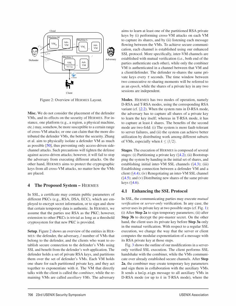
Figure 2: Overview of HERMES Layout.
Misc. We do not consider the placement of the defenderVMs, and its effects on the security of HERMES. For in-stance, one platform (e.g., a region, a physical machine,etc.) may, somehow, be more susceptible to a certain rangeof cross-VM attacks; or one can claim that the more dis-tributed the defender VMs, the better the security. Zhanget al. aim to physically isolate a defender VM as muchas possible [50], thus preventing only access-driven side-channel attacks. Such precautions will tighten the defenseagainst access-driven attacks; however, it will fail to stopthe adversary from executing different attacks. On theother hand, HERMES aims to protect the cryptographickeys from all cross-VM attacks, no matter how the VMsare placed.
4 The Proposed System – HERMES
In SSL, a certificate may contain public parameters ofdifferent PKCs (e.g., RSA, DSA, ECC), which are em-ployed to encrypt secret information, or to sign and showthat certain temporary data is authentic. In HERMES, weassume that the parties use RSA as the PKC; however,extension to other PKCs is trivial as long as a thresholdcryptosystem for that new PKC is provided.
Setup. Figure 2 shows an overview of the entities in HER-MES: the defender, the adversary, l number of VMs thatbelong to the defender, and the clients who want to es-tablish secure connection to the defender’s VMs usingSSL and benefit from the defender’s web application. Thedefender holds a set of private RSA keys, and partitionsthem over the set of defender’s VMs. Each VM holdsone share for each partitioned private key, and they acttogether to exponentiate with it. The VM that directlytalks with the client is called the combiner, while the re-maining VMs are called auxiliary VMs. The adversary
aims to learn at least one of the partitioned RSA privatekeys by (i) performing cross-VM attacks on each VMto capture its shares, and by (ii) listening each messageflowing between the VMs. To achieve secure communi-cation, each channel is established using our enhancedSSL protocol. More specifically, inter-VM channels areestablished with mutual verification (i.e., both end of theparties authenticate each other), while only the combinerVM is authenticated in a channel between that VM anda client/defender. The defender re-shares the same pri-vate keys every τ seconds. The time window betweentwo consecutive re-sharing moments will be referred toas an epoch, while the shares of a private key in any twosessions are independent.
Modes. HERMES has two modes of operation, namelyD-RSA and T-RSA modes, using the corresponding RSAvariant (cf. §2.2). When the system runs in D-RSA mode,the adversary has to capture all shares of a private keyto learn the key itself; whereas in T-RSA mode, it hasto capture at least k shares. The benefits of the secondmode are two-fold: (i) The system is more fault-tolerantto server failures, and (ii) the system can achieve betterutilization by distributing work among different subsetsof VMs, especially when k ≤ (l/2).
Stages. The execution of HERMES is composed of severalstages: (i) Partitioning a private key (§4.2); (ii) Bootstrap-ping the system by handing in the initial set of shares, andestablishing initial inter-VM SSL channels (§4.3); (iii)Establishing connection between a defender VM and aclient (§4.4); (iv) Renegotiating an inter-VM SSL channel(§4.5); and (v) Distributing new shares of the same privatekeys (§4.6).
4.1 Enhancing the SSL ProtocolIn SSL, the communicating parties may execute mutualverification or server-only verification. In any case, theserver uses its private key at two possible steps (cf. Fig. 1):(i) After Step 2a to sign temporary parameters; (ii) afterStep 3b to decrypt the pre-master secret. On the otherhand, the client uses its private key before Step 3a onlyin the mutual verification. With respect to a regular SSLexecution, we change the way that the server or clientcomputes the modular exponentiation of a message withits RSA private key at those steps.
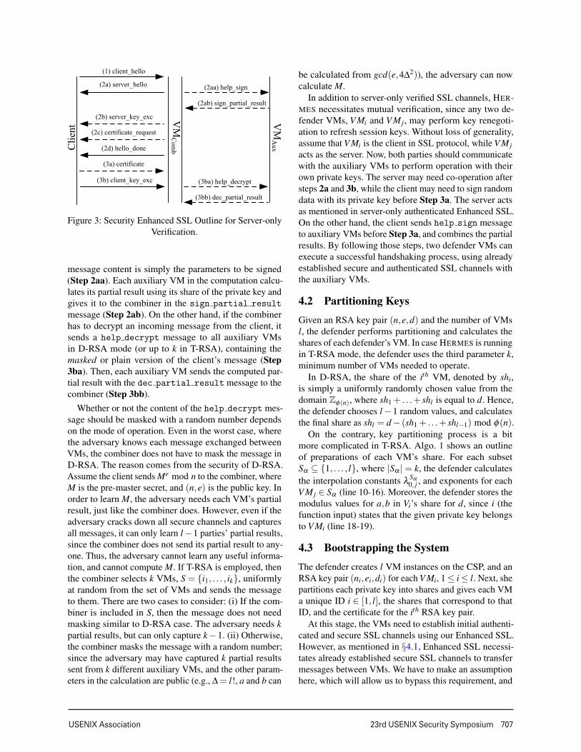
Fig. 3 shows the outline of our modifications in a server-only verified SSL execution. The client performs SSLhandshake with the combiner, while the VMs communi-cate over already established secure channels. After Step2a, the combiner may create temporary key parametersand sign them in collaboration with the auxiliary VMs.It sends a help sign message to all auxiliary VMs inD-RSA mode (or up to k in T-RSA mode), where the
USENIX Association 23rd USENIX Security Symposium 707
Figure 3: Security Enhanced SSL Outline for Server-onlyVerification.
message content is simply the parameters to be signed(Step 2aa). Each auxiliary VM in the computation calcu-lates its partial result using its share of the private key andgives it to the combiner in the sign partial result
message (Step 2ab). On the other hand, if the combinerhas to decrypt an incoming message from the client, itsends a help decrypt message to all auxiliary VMsin D-RSA mode (or up to k in T-RSA), containing themasked or plain version of the client’s message (Step3ba). Then, each auxiliary VM sends the computed par-tial result with the dec partial result message to thecombiner (Step 3bb).
Whether or not the content of the help decrypt mes-sage should be masked with a random number dependson the mode of operation. Even in the worst case, wherethe adversary knows each message exchanged betweenVMs, the combiner does not have to mask the message inD-RSA. The reason comes from the security of D-RSA.Assume the client sends Me mod n to the combiner, whereM is the pre-master secret, and (n,e) is the public key. Inorder to learn M, the adversary needs each VM’s partialresult, just like the combiner does. However, even if theadversary cracks down all secure channels and capturesall messages, it can only learn l−1 parties’ partial results,since the combiner does not send its partial result to any-one. Thus, the adversary cannot learn any useful informa-tion, and cannot compute M. If T-RSA is employed, thenthe combiner selects k VMs, S = {i1, . . . , ik}, uniformlyat random from the set of VMs and sends the messageto them. There are two cases to consider: (i) If the com-biner is included in S, then the message does not needmasking similar to D-RSA case. The adversary needs kpartial results, but can only capture k−1. (ii) Otherwise,the combiner masks the message with a random number;since the adversary may have captured k partial resultssent from k different auxiliary VMs, and the other param-eters in the calculation are public (e.g., ∆ = l!, a and b can
be calculated from gcd(e,4∆2)), the adversary can nowcalculate M.
In addition to server-only verified SSL channels, HER-MES necessitates mutual verification, since any two de-fender VMs, V Mi and V Mj, may perform key renegoti-ation to refresh session keys. Without loss of generality,assume that V Mi is the client in SSL protocol, while V Mjacts as the server. Now, both parties should communicatewith the auxiliary VMs to perform operation with theirown private keys. The server may need co-operation aftersteps 2a and 3b, while the client may need to sign randomdata with its private key before Step 3a. The server actsas mentioned in server-only authenticated Enhanced SSL.On the other hand, the client sends help sign messageto auxiliary VMs before Step 3a, and combines the partialresults. By following those steps, two defender VMs canexecute a successful handshaking process, using alreadyestablished secure and authenticated SSL channels withthe auxiliary VMs.
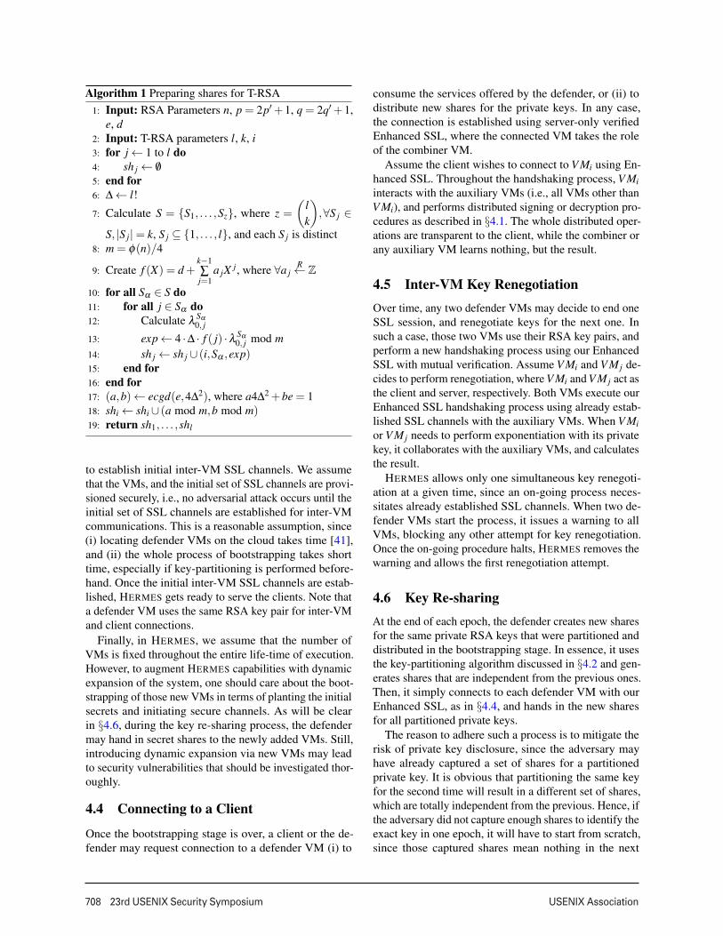
4.2 Partitioning KeysGiven an RSA key pair (n,e,d) and the number of VMsl, the defender performs partitioning and calculates theshares of each defender’s VM. In case HERMES is runningin T-RSA mode, the defender uses the third parameter k,minimum number of VMs needed to operate.
In D-RSA, the share of the ith VM, denoted by shi,is simply a uniformly randomly chosen value from thedomain Zφ(n), where sh1 + . . .+ shl is equal to d. Hence,the defender chooses l −1 random values, and calculatesthe final share as shl = d − (sh1 + . . .+ shl−1) mod φ(n).
On the contrary, key partitioning process is a bitmore complicated in T-RSA. Algo. 1 shows an outlineof preparations of each VM’s share. For each subsetSα ⊆ {1, . . . , l}, where |Sα |= k, the defender calculatesthe interpolation constants λ Sα
0, j , and exponents for eachV Mj ∈ Sα (line 10-16). Moreover, the defender stores themodulus values for a,b in Vi’s share for d, since i (thefunction input) states that the given private key belongsto V Mi (line 18-19).
4.3 Bootstrapping the SystemThe defender creates l VM instances on the CSP, and anRSA key pair (ni,ei,di) for each V Mi, 1 ≤ i ≤ l. Next, shepartitions each private key into shares and gives each VMa unique ID i ∈ [1, l], the shares that correspond to thatID, and the certificate for the ith RSA key pair.
At this stage, the VMs need to establish initial authenti-cated and secure SSL channels using our Enhanced SSL.However, as mentioned in §4.1, Enhanced SSL necessi-tates already established secure SSL channels to transfermessages between VMs. We have to make an assumptionhere, which will allow us to bypass this requirement, and
708 23rd USENIX Security Symposium USENIX Association
Algorithm 1 Preparing shares for T-RSA1: Input: RSA Parameters n, p = 2p′+1, q = 2q′+1,
e, d2: Input: T-RSA parameters l, k, i3: for j ← 1 to l do4: sh j ← /05: end for6: ∆ ← l!
7: Calculate S = {S1, . . . ,Sz}, where z =
(lk
),∀S j ∈
S, |S j|= k, S j ⊆ {1, . . . , l}, and each S j is distinct8: m = φ(n)/4
9: Create f (X) = d +k−1∑j=1
a jX j, where ∀a jR← Z
10: for all Sα ∈ S do11: for all j ∈ Sα do12: Calculate λ Sα
0, j
13: exp ← 4 ·∆ · f ( j) ·λ Sα0, j mod m
14: sh j ← sh j ∪ (i,Sα ,exp)15: end for16: end for17: (a,b)← ecgd(e,4∆2), where a4∆2 +be = 118: shi ← shi ∪ (a mod m,b mod m)19: return sh1, . . . ,shl
to establish initial inter-VM SSL channels. We assumethat the VMs, and the initial set of SSL channels are provi-sioned securely, i.e., no adversarial attack occurs until theinitial set of SSL channels are established for inter-VMcommunications. This is a reasonable assumption, since(i) locating defender VMs on the cloud takes time [41],and (ii) the whole process of bootstrapping takes shorttime, especially if key-partitioning is performed before-hand. Once the initial inter-VM SSL channels are estab-lished, HERMES gets ready to serve the clients. Note thata defender VM uses the same RSA key pair for inter-VMand client connections.
Finally, in HERMES, we assume that the number ofVMs is fixed throughout the entire life-time of execution.However, to augment HERMES capabilities with dynamicexpansion of the system, one should care about the boot-strapping of those new VMs in terms of planting the initialsecrets and initiating secure channels. As will be clearin §4.6, during the key re-sharing process, the defendermay hand in secret shares to the newly added VMs. Still,introducing dynamic expansion via new VMs may leadto security vulnerabilities that should be investigated thor-oughly.
4.4 Connecting to a Client
Once the bootstrapping stage is over, a client or the de-fender may request connection to a defender VM (i) to
consume the services offered by the defender, or (ii) todistribute new shares for the private keys. In any case,the connection is established using server-only verifiedEnhanced SSL, where the connected VM takes the roleof the combiner VM.
Assume the client wishes to connect to V Mi using En-hanced SSL. Throughout the handshaking process, V Miinteracts with the auxiliary VMs (i.e., all VMs other thanV Mi), and performs distributed signing or decryption pro-cedures as described in §4.1. The whole distributed oper-ations are transparent to the client, while the combiner orany auxiliary VM learns nothing, but the result.
4.5 Inter-VM Key RenegotiationOver time, any two defender VMs may decide to end oneSSL session, and renegotiate keys for the next one. Insuch a case, those two VMs use their RSA key pairs, andperform a new handshaking process using our EnhancedSSL with mutual verification. Assume V Mi and V Mj de-cides to perform renegotiation, where V Mi and V Mj act asthe client and server, respectively. Both VMs execute ourEnhanced SSL handshaking process using already estab-lished SSL channels with the auxiliary VMs. When V Mior V Mj needs to perform exponentiation with its privatekey, it collaborates with the auxiliary VMs, and calculatesthe result.
HERMES allows only one simultaneous key renegoti-ation at a given time, since an on-going process neces-sitates already established SSL channels. When two de-fender VMs start the process, it issues a warning to allVMs, blocking any other attempt for key renegotiation.Once the on-going procedure halts, HERMES removes thewarning and allows the first renegotiation attempt.
4.6 Key Re-sharingAt the end of each epoch, the defender creates new sharesfor the same private RSA keys that were partitioned anddistributed in the bootstrapping stage. In essence, it usesthe key-partitioning algorithm discussed in §4.2 and gen-erates shares that are independent from the previous ones.Then, it simply connects to each defender VM with ourEnhanced SSL, as in §4.4, and hands in the new sharesfor all partitioned private keys.
The reason to adhere such a process is to mitigate therisk of private key disclosure, since the adversary mayhave already captured a set of shares for a partitionedprivate key. It is obvious that partitioning the same keyfor the second time will result in a different set of shares,which are totally independent from the previous. Hence, ifthe adversary did not capture enough shares to identify theexact key in one epoch, it will have to start from scratch,since those captured shares mean nothing in the next

USENIX Association 23rd USENIX Security Symposium 709
Setup(1,1) (2,2) (3,3) (4,4) (5,5) (6,6) (7,7) (8,8) (9,9) (10,10)
1 Cli.Total 2.65 8.96 10.40 11.57 15.40 16.13 13.58 17.44 14.05 13.76Network − 2.77 2.82 2.75 2.29 2.54 2.37 1.89 1.07 1.56Combine − 1.78 1.76 1.82 2.25 2.18 1.87 1.99 2.00 1.93
10 Cli.Total 5.54 31.74 37.85 45.87 43.59 40.82 48.65 52.77 50.64 52.82Network − 19.42 21.67 14.29 18.92 19.89 25.69 21.68 18.11 14.09Combine − 1.95 2.05 2.22 2.20 2.18 1.87 2.17 2.58 2.23
100 Cli.Total 40.90 179.01 178.14 187.67 209.74 212.33 229.38 246.39 257.03 269.73Network − 121.05 113.36 122.96 108.82 125.52 108.25 106.98 98.71 113.15Combine − 2.16 2.14 2.01 2.10 2.09 2.03 2.11 2.81 2.28
1000 Cli.Total 146.94 640.40 728.56 928.75 1023.75 904.59 989.32 1097.64 1001.06 1174.54Network − 210.36 197.28 202.08 229.03 240.42 204.30 284.05 237.72 233.41Combine − 2.26 2.08 1.96 2.18 2.17 2.20 2.43 2.24 2.62
Table 1: Average Connection, Network, and Combining Time Spent for D-RSA in milliseconds
epoch. The defender VMs do not immediately start usingthe new keys, since each defender should get the newshares, otherwise HERMES would have synchronizationproblems. Instead, a defender VM broadcasts a messageto announce that it has the new shares. When all defenderVMs have the new shares, they pass on to the next epoch,start using the new shares, and zeroise the old shares toleave no trace. Till then, the VMs continue using the oldepoch shares.
5 Evaluation
We have implemented a prototype of HERMES atopthe most commonly used open source SSL library,OpenSSL [10] v1.0.1e, the latest version as of this writing.Our implementation is a separate shared library compat-ible with the OpenSSL’s Engine API. Without changingthe OpenSSL source, programmers can plug-in our imple-mentation and vary the way that RSA computations areperformed with the private key. Meanwhile, we have alsocreated multi-threaded applications (i) for the auxiliaryVMs to establish SSL connections with the combiner VM,and to perform mathematical operations (e.g., exponenti-ation with the private key share); (ii) for the defender topartition the RSA private keys and hand in the shares toeach defender VM. In this section, we present our evalua-tion result.
5.1 Experiment Setup
Case Studies. As it is challenging to exhaustively testHERMES with all the network benchmarks, we evaluatedour system using a micro benchmark to profile the per-formance, and two representative case studies, in whichSSL connection is necessary. The micro benchmark ex-periments evaluate the performance under varying systemsetups to target possible bottlenecks. Once the system dy-namics are profiled, we execute two real-life case studiesand check any efficiency deficits. The first case study is a
web server, for which we used Apache HTTP Server [7]v2.4.4. A client connects to the server via HTTPS, andretrieves the default web page that comes with the appli-cation, which is a static HTML page of size 2KB. Thesecond case study is a mail server using Postfix v2.10 [11].On top of that, we installed Dovecot [8] v2.2.4 as theIMAP(s)/POP3(s) server. A client connects to the Dove-cot instance via IMAPS and checks the status of a mailbox,which contains a single mail of size 1KB. Both server ap-plications are executed with the keep alive property off(i.e., the server does not store SSL sessions, and performsa new handshake for every connection attempt by theclients).
One may argue that testing the web and mail serverswith such low-sized content is applicable to real-worldcase. It is true that almost all web sites serve contentsthat may have much larger sizes. However, the purpose ofthe experiments is to put as much pressure as possible toHERMES in the given web and mail server case studies. Aswill be clear in the results, as the number of connectionsperformed per unit time increases, HERMES acts moreefficiently due to decreased network overhead. Hence,increasing the content sizes would increase the amount oftime the server spends on processing a query, and decreasethe number of requests per unit time. Instead, we used 1and 2KB contents, and tried pushing HERMES as muchas possible.
Benchmarks. To extract micro benchmark results, we de-veloped applications that connect to the given defenderVM, using given number of concurrent clients. For theweb server application, we used two different benchmark-ing tools: Apache HTTP server benchmarking tool [5](AB) v2.4.4, which allows us to send HTTPS queries witha variety of execution options; and Apache JMeter [6](AJ) v2.9, where we used the default HTTPS request sam-pler that comes with the standard AJ binaries. For themail server application, we used AJ again, with the de-fault mail reader sampler. Similar to the server-side, we
710 23rd USENIX Security Symposium USENIX Association
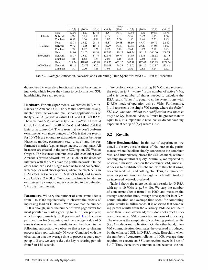
Setup(10,2) (10,3) (10,4) (10,5) (10,6) (10,7) (10,8) (10,9) (10,10)
1 ClientsTotal 12.06 12.27 13.44 11.57 16.10 17.94 16.80 19.80 13.76Network 4.97 5.14 4.89 2.75 5.07 5.59 5.29 1.15 1.56Combine 0.52 0.56 0.58 1.82 2.36 1.56 2.44 2.20 1.93
10 ClientsTotal 19.78 23.22 28.14 45.87 39.48 48.99 49.97 60.70 52.82Network 9.72 10.15 10.19 14.29 16.30 23.15 27.17 34.03 14.09Combine 1.27 1.07 1.26 2.22 2.42 2.64 3.09 2.81 2.23
100 ClientsTotal 54.90 71.07 88.31 187.67 130.17 163.24 182.12 206.00 269.73Network 11.77 25.27 37.77 122.96 69.74 84.05 82.96 121.32 113.15Combine 1.24 1.62 1.74 2.01 2.15 2.34 2.80 3.01 2.28
1000 ClientsTotal 318.24 418.07 435.98 928.75 653.12 642.48 877.42 995.89 1174.54Network 88.12 123.72 130.21 202.08 196.29 212.05 214.20 216.97 233.41Combine 1.50 2.20 1.85 1.96 2.08 2.52 2.82 3.24 2.62
Table 2: Average Connection, Network, and Combining Time Spent for Fixed l = 10 in milliseconds
did not use the keep alive functionality in the benchmark-ing tools, which forces the clients to perform a new SSLhandshaking for each request.
Hardware. For our experiments, we created 10 VM in-stances on Amazon EC2. The VM that serves that is aug-mented with the web and mail server applications is ofthe type m1.xlarge with 4 virtual CPU and 15GB of RAM.The remaining VMs are of the type m1.small with 1 virtualCPU, 1 virtual core, 1.7GB of RAM, and 64-bit Red HatEnterprise Linux 6.4. The reason that we don’t performexperiments with more number of VMs is that our resultsfor 10 VMs are enough to extrapolate relations betweenHERMES modes, parameters (e.g., l, k, τ), and the per-formance metrics (e.g., average latency, throughput). Allinstances are created in the same EC2 region, US-West atOregon. The instances communicate with each other overAmazon’s private network, while a client or the defenderinteracts with the VMs over the public network. On theother hand, we used a single machine to send connection,web page, or mail check queries, where the machine is anIBM x3500m3 server with 16GB of RAM, and 4 quad-core CPUs at 2.4 GHz. Our client machine is located inour university campus, and is connected to the defenderVMs over the Internet.
Parameters. We vary the number of concurrent clientsfrom 1 to 1000 exponentially to observe the effects ofincreasing load on HERMES. We believe that the number1000 is enough, since the number of web page views formost popular web sites goes up to 37 billion per year,which is approximately 1100 per second [1, 2]. Each ex-periment ran for 5 minutes, and the average value of 5runs is shown as the final result. As will be shown in thefollowing subsection, we observe that a key re-sharingprocess takes approximately 50 msec. Combined with theobservation that the average time to process a query maygo up to 2 sec, we vary τ (i.e., the key re-sharing period)from 5 to 125 seconds.
We perform experiments using 10 VMs, and representthe setup as (l,k), where l is the number of active VMs,and k is the number of shares needed to calculate theRSA result. When l is equal to k, the system runs withD-RSA mode of operation using l VMs. Furthermore,(1,1) represents the single VM setup, where the defaultSSL (i.e., the one without our modification and there isonly one key) is used. Also, as l must be greater than orequal to k, it is important to note that we do not have anyexperiment set up of (l,k) where l < k.
5.2 Results
Micro Benchmarking. In this set of experiments, weaimed to observe the sole effects of HERMES on the perfor-mance, where the client simply connects to the combinerVM, and immediately closes the SSL channel, withoutsending any additional query. Naturally, we expected toobserve a massive load on the combiner VM, since allit does is to establish SSL channel with the client usingour enhanced SSL, and nothing else. Thus, the number ofrequests per unit time will be high, which will introducean increased network overhead.
Table 1 shows the micro benchmark results for D-RSAwith up to 10 VMs (e.g., l = 10). We vary the numberof concurrent clients from 1 to 1000, and measure theaverage connection time, average time spent for inter-VMcommunication, and average time spent for combiningpartial results in milliseconds. It is observed that combin-ing partial results from the auxiliary VMs do not incurmore than 3 msec overhead; thus, does not affect a suc-cessful enhanced SSL connection in terms of efficiency.The reason is the simplicity of combining partial results(i.e., l modular multiplication). On the other hand, inter-VM communication dominates the overhead introducedby the enhanced SSL in D-RSA mode. Especially whenthe number of concurrent clients is 1000, average timerequired to execute an SSL connection exceeds 1 sec ifl > 7. Thus, the network communication becomes the bot-
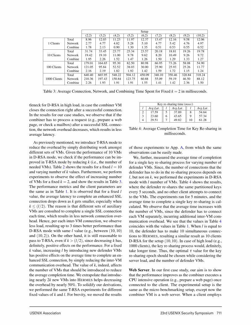
USENIX Association 23rd USENIX Security Symposium 711
Setup(2,2) (3,2) (4,2) (5,2) (6,2) (7,2) (8,2) (9,2) (10,2)
1 ClientsTotal 8.96 12.03 11.23 11.97 12.37 13.47 12.16 9.58 12.06Network 2.77 4.77 4.82 5.28 5.10 4.77 5.42 4.76 4.97Combine 1.78 2.13 0.90 1.30 1.35 0.51 0.53 0.55 0.52
10 ClientsTotal 31.74 33.45 23.77 25.34 23.57 20.18 18.81 19.26 19.78Network 19.42 19.10 11.00 9.78 9.62 8.20 10.49 9.26 9.72Combine 1.95 2.26 1.52 1.47 1.26 1.50 1.29 1.33 1.27
100 ClientsTotal 179.01 164.65 95.30 82.50 80.98 66.95 73.26 58.08 54.90Network 121.05 95.84 52.52 38.03 30.00 25.90 25.93 25.26 11.77Combine 2.16 2.19 1.82 1.92 1.42 1.59 1.72 1.15 1.24
1000 ClientsTotal 640.40 665.95 548.22 504.12 450.09 340.10 350.46 320.84 318.24Network 210.36 197.43 150.84 123.75 60.88 55.09 59.19 46.50 88.12Combine 2.26 1.93 1.91 1.91 1.55 1.41 1.42 2.36 1.50
Table 3: Average Connection, Network, and Combining Time Spent for Fixed k = 2 in milliseconds.
tleneck for D-RSA in high load, in case the combiner VMcloses the connection right after a successful connection.In the results for our case studies, we observe that if thecombiner has to process a request (e.g., prepare a webpage, or check a mailbox) after a successful SSL connec-tion, the network overhead decreases, which results in lessaverage latency.
As previously mentioned, we introduce T-RSA mode toreduce the overhead by simply distributing work amongstdifferent sets of VMs. Given the performance of 10 VMsin D-RSA mode, we check if the performance can be im-proved in T-RSA mode by reducing k (i.e., the number ofneeded VMs). Table 2 shows the results for a fixed l = 10and varying number of k values. Furthermore, we performexperiments to observe the effect of increasing numberof VMs for a fixed k = 2, and show the results in Table 3.The performance metrics and the client parameters arethe same as in Table 1. It is observed that for a fixed lvalue, the average latency to complete an enhanced SSLconnection drops down as k gets smaller, especially whenk ≤ (l/2). The reason is that different sets of auxiliaryVMs are consulted to complete a single SSL connectioneach time, which results in less network connection over-head. Hence, per each inter-VM connection, we observeless load, resulting up to 3 times better performance thanD-RSA mode with same l value (e.g., between (10,10)and (10,2)). On the other hand, it is still reasonable topass to T-RSA, even if k > (l/2), since decreasing k has,definitely, positive effects on the performance. For a fixedk value, increasing l by introducing new defender VMshas positive effects on the average time to complete an en-hanced SSL connection, by simply reducing the inter-VMcommunication overhead. The value of k, indeed, affectsthe number of VMs that should be introduced to reducethe average completion time. We extrapolate that introduc-ing nearly 2k new VMs into HERMES helps decreasingthe overhead by nearly 50%. To solidify our derivations,we performed the same T-RSA experiments for differentfixed values of k and l. For brevity, we moved the results
Key re-sharing time (msec)l Avg.Lat. l Avg.Lat. l Avg.Lat.2 17.59 5 37.89 8 54.643 23.60 6 43.65 9 57.344 29.51 7 49.82 10 61.28
Table 4: Average Completion Time for Key Re-sharing inmilliseconds.
of those experiments to App. A, from which the sameobservations can be easily made.
We, further, measured the average time of completionfor a single key re-sharing process for varying number ofdefender VMs. Since, the number of connections that thedefender has to do in the re-sharing process depends onl, but not on k, we performed the experiments in D-RSAmode with l number of VMs. Table 4 shows the results,where the defender re-shares the same partitioned keysevery 5 seconds, and no other client attempts to connectto the VMs. The experiments ran for 5 minutes, and theaverage time to complete a single key re-sharing is cal-culated. We observe that the average time increases withthe number of VMs, since the defender has to connecteach VM separately, incurring additional inter-VM com-munication overhead. We see that the values in Table 4coincides with the values in Table 1. When l is equal to10, the defender has to make 10 simultaneous connec-tions to HERMES, resulting a similar result as 10 clientsD-RSA for the setup (10,10). In case of high load (e.g.,1000 clients), the key re-sharing process would, definitely,take longer time. Thus, the optimal τ value for the keyre-sharing epoch should be chosen while considering theserver load, and the number of defender VMs.
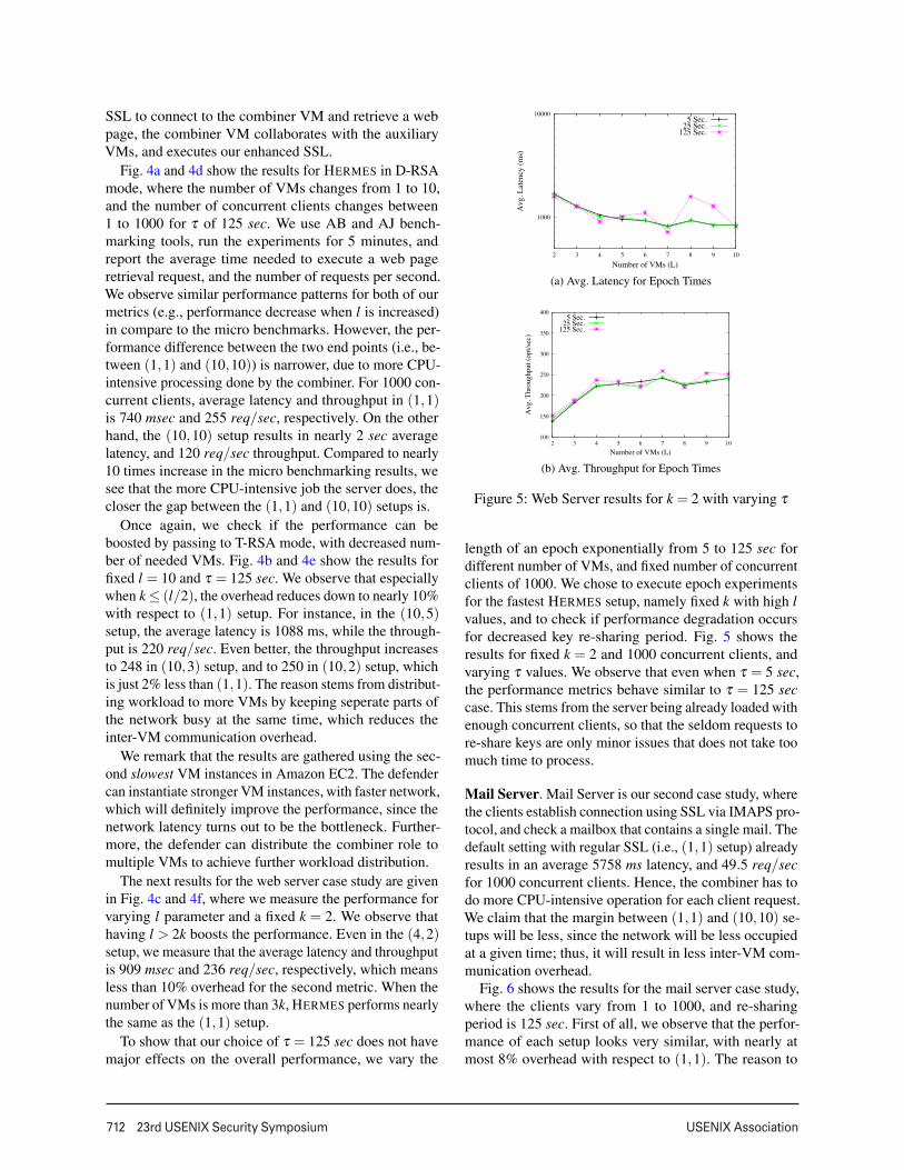
Web Server. In our first case study, our aim is to showthat the performance improves as the combiner executes aCPU intensive operation (e.g., prepare a web page) onceconnected to the client. The experimental setup is thesame as the micro benchmarking setup, except now thecombiner VM is a web server. When a client employs
712 23rd USENIX Security Symposium USENIX Association
SSL to connect to the combiner VM and retrieve a webpage, the combiner VM collaborates with the auxiliaryVMs, and executes our enhanced SSL.
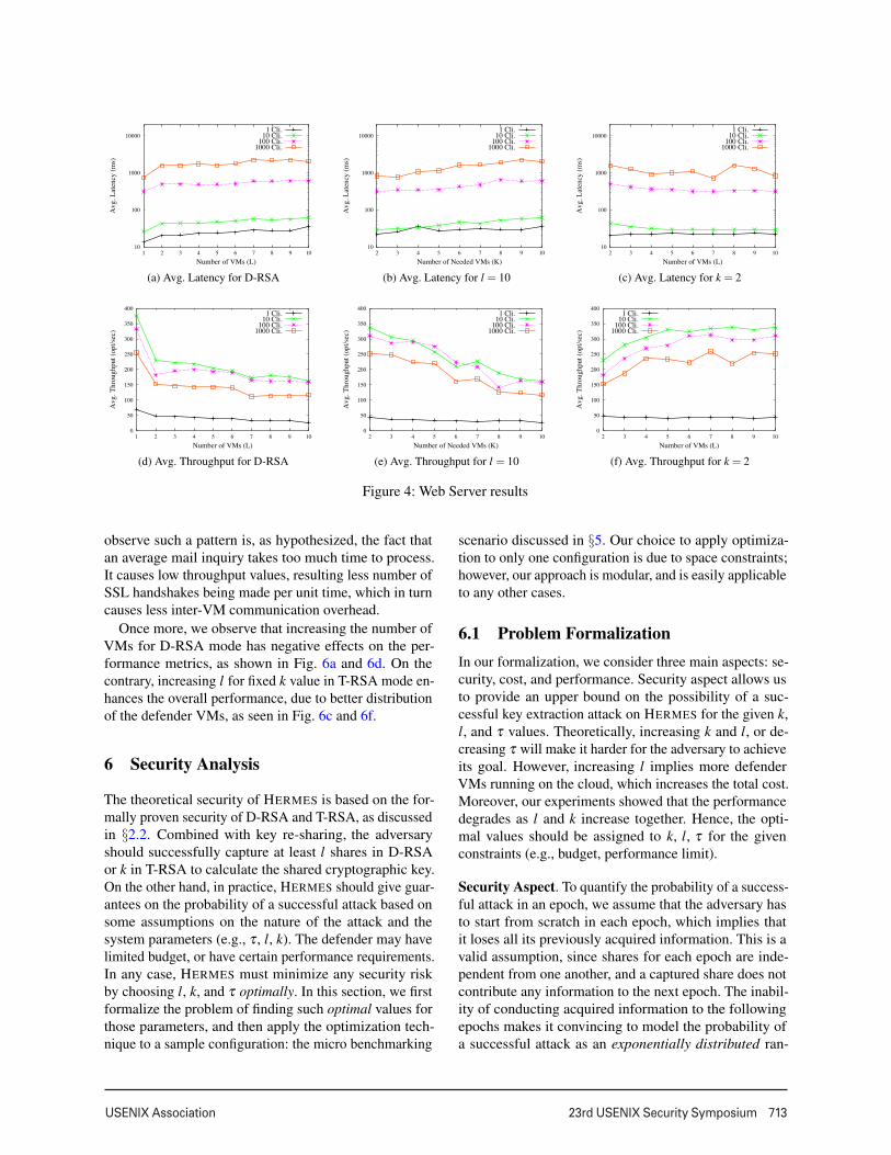
Fig. 4a and 4d show the results for HERMES in D-RSAmode, where the number of VMs changes from 1 to 10,and the number of concurrent clients changes between1 to 1000 for τ of 125 sec. We use AB and AJ bench-marking tools, run the experiments for 5 minutes, andreport the average time needed to execute a web pageretrieval request, and the number of requests per second.We observe similar performance patterns for both of ourmetrics (e.g., performance decrease when l is increased)in compare to the micro benchmarks. However, the per-formance difference between the two end points (i.e., be-tween (1,1) and (10,10)) is narrower, due to more CPU-intensive processing done by the combiner. For 1000 con-current clients, average latency and throughput in (1,1)is 740 msec and 255 req/sec, respectively. On the otherhand, the (10,10) setup results in nearly 2 sec averagelatency, and 120 req/sec throughput. Compared to nearly10 times increase in the micro benchmarking results, wesee that the more CPU-intensive job the server does, thecloser the gap between the (1,1) and (10,10) setups is.
Once again, we check if the performance can beboosted by passing to T-RSA mode, with decreased num-ber of needed VMs. Fig. 4b and 4e show the results forfixed l = 10 and τ = 125 sec. We observe that especiallywhen k ≤ (l/2), the overhead reduces down to nearly 10%with respect to (1,1) setup. For instance, in the (10,5)setup, the average latency is 1088 ms, while the through-put is 220 req/sec. Even better, the throughput increasesto 248 in (10,3) setup, and to 250 in (10,2) setup, whichis just 2% less than (1,1). The reason stems from distribut-ing workload to more VMs by keeping seperate parts ofthe network busy at the same time, which reduces theinter-VM communication overhead.
We remark that the results are gathered using the sec-ond slowest VM instances in Amazon EC2. The defendercan instantiate stronger VM instances, with faster network,which will definitely improve the performance, since thenetwork latency turns out to be the bottleneck. Further-more, the defender can distribute the combiner role tomultiple VMs to achieve further workload distribution.
The next results for the web server case study are givenin Fig. 4c and 4f, where we measure the performance forvarying l parameter and a fixed k = 2. We observe thathaving l > 2k boosts the performance. Even in the (4,2)setup, we measure that the average latency and throughputis 909 msec and 236 req/sec, respectively, which meansless than 10% overhead for the second metric. When thenumber of VMs is more than 3k, HERMES performs nearlythe same as the (1,1) setup.
To show that our choice of τ = 125 sec does not havemajor effects on the overall performance, we vary the
1000
10000
2 3 4 5 6 7 8 9 10
Avg
. Lat
ency
(ms)
Number of VMs (L)
5 Sec.25 Sec.
125 Sec.
(a) Avg. Latency for Epoch Times
100
150
200
250
300
350
400
2 3 4 5 6 7 8 9 10
Avg
. Thr
ough
put (
opt/s
ec)
Number of VMs (L)
5 Sec.25 Sec.
125 Sec.
(b) Avg. Throughput for Epoch Times
Figure 5: Web Server results for k = 2 with varying τ
length of an epoch exponentially from 5 to 125 sec fordifferent number of VMs, and fixed number of concurrentclients of 1000. We chose to execute epoch experimentsfor the fastest HERMES setup, namely fixed k with high lvalues, and to check if performance degradation occursfor decreased key re-sharing period. Fig. 5 shows theresults for fixed k = 2 and 1000 concurrent clients, andvarying τ values. We observe that even when τ = 5 sec,the performance metrics behave similar to τ = 125 seccase. This stems from the server being already loaded withenough concurrent clients, so that the seldom requests tore-share keys are only minor issues that does not take toomuch time to process.
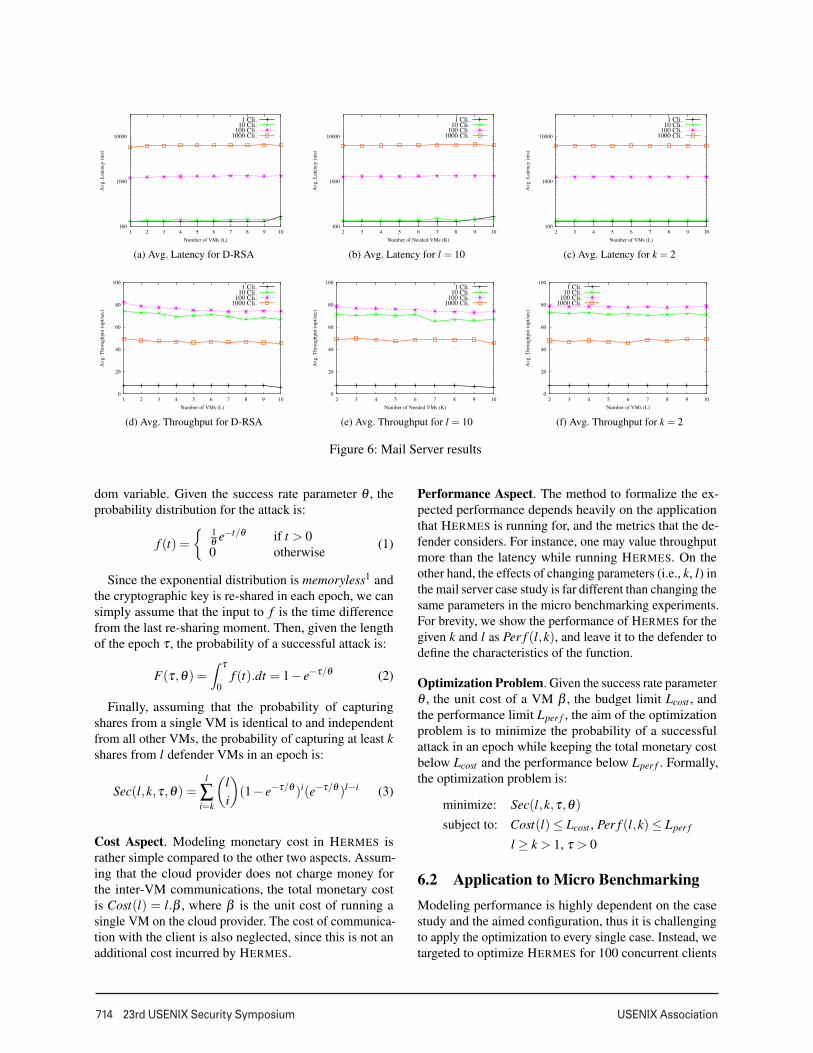
Mail Server. Mail Server is our second case study, wherethe clients establish connection using SSL via IMAPS pro-tocol, and check a mailbox that contains a single mail. Thedefault setting with regular SSL (i.e., (1,1) setup) alreadyresults in an average 5758 ms latency, and 49.5 req/secfor 1000 concurrent clients. Hence, the combiner has todo more CPU-intensive operation for each client request.We claim that the margin between (1,1) and (10,10) se-tups will be less, since the network will be less occupiedat a given time; thus, it will result in less inter-VM com-munication overhead.
Fig. 6 shows the results for the mail server case study,where the clients vary from 1 to 1000, and re-sharingperiod is 125 sec. First of all, we observe that the perfor-mance of each setup looks very similar, with nearly atmost 8% overhead with respect to (1,1). The reason to
USENIX Association 23rd USENIX Security Symposium 713
10
100
1000
10000
1 2 3 4 5 6 7 8 9 10
Avg
. Lat
ency
(ms)
Number of VMs (L)
1 Cli.10 Cli.
100 Cli.1000 Cli.
(a) Avg. Latency for D-RSA
10
100
1000
10000
2 3 4 5 6 7 8 9 10
Avg
. Lat
ency
(ms)
Number of Needed VMs (K)
1 Cli.10 Cli.
100 Cli.1000 Cli.
(b) Avg. Latency for l = 10
10
100
1000
10000
2 3 4 5 6 7 8 9 10
Avg
. Lat
ency
(ms)
Number of VMs (L)
1 Cli.10 Cli.
100 Cli.1000 Cli.
(c) Avg. Latency for k = 2
0
50
100
150
200
250
300
350
400
1 2 3 4 5 6 7 8 9 10
Avg
. Thr
ough
put (
opt/s
ec)
Number of VMs (L)
1 Cli.10 Cli.
100 Cli.1000 Cli.
(d) Avg. Throughput for D-RSA
0
50
100
150
200
250
300
350
400
2 3 4 5 6 7 8 9 10
Avg
. Thr
ough
put (
opt/s
ec)
Number of Needed VMs (K)
1 Cli.10 Cli.
100 Cli.1000 Cli.
(e) Avg. Throughput for l = 10
0
50
100
150
200
250
300
350
400
2 3 4 5 6 7 8 9 10
Avg
. Thr
ough
put (
opt/s
ec)
Number of VMs (L)
1 Cli.10 Cli.
100 Cli.1000 Cli.
(f) Avg. Throughput for k = 2
Figure 4: Web Server results
observe such a pattern is, as hypothesized, the fact thatan average mail inquiry takes too much time to process.It causes low throughput values, resulting less number ofSSL handshakes being made per unit time, which in turncauses less inter-VM communication overhead.
Once more, we observe that increasing the number ofVMs for D-RSA mode has negative effects on the per-formance metrics, as shown in Fig. 6a and 6d. On thecontrary, increasing l for fixed k value in T-RSA mode en-hances the overall performance, due to better distributionof the defender VMs, as seen in Fig. 6c and 6f.
6 Security Analysis
The theoretical security of HERMES is based on the for-mally proven security of D-RSA and T-RSA, as discussedin §2.2. Combined with key re-sharing, the adversaryshould successfully capture at least l shares in D-RSAor k in T-RSA to calculate the shared cryptographic key.On the other hand, in practice, HERMES should give guar-antees on the probability of a successful attack based onsome assumptions on the nature of the attack and thesystem parameters (e.g., τ , l, k). The defender may havelimited budget, or have certain performance requirements.In any case, HERMES must minimize any security riskby choosing l, k, and τ optimally. In this section, we firstformalize the problem of finding such optimal values forthose parameters, and then apply the optimization tech-nique to a sample configuration: the micro benchmarking
scenario discussed in §5. Our choice to apply optimiza-tion to only one configuration is due to space constraints;however, our approach is modular, and is easily applicableto any other cases.
6.1 Problem FormalizationIn our formalization, we consider three main aspects: se-curity, cost, and performance. Security aspect allows usto provide an upper bound on the possibility of a suc-cessful key extraction attack on HERMES for the given k,l, and τ values. Theoretically, increasing k and l, or de-creasing τ will make it harder for the adversary to achieveits goal. However, increasing l implies more defenderVMs running on the cloud, which increases the total cost.Moreover, our experiments showed that the performancedegrades as l and k increase together. Hence, the opti-mal values should be assigned to k, l, τ for the givenconstraints (e.g., budget, performance limit).
Security Aspect. To quantify the probability of a success-ful attack in an epoch, we assume that the adversary hasto start from scratch in each epoch, which implies thatit loses all its previously acquired information. This is avalid assumption, since shares for each epoch are inde-pendent from one another, and a captured share does notcontribute any information to the next epoch. The inabil-ity of conducting acquired information to the followingepochs makes it convincing to model the probability ofa successful attack as an exponentially distributed ran-
714 23rd USENIX Security Symposium USENIX Association
100
1000
10000
1 2 3 4 5 6 7 8 9 10
Avg
. Lat
ency
(ms)
Number of VMs (L)
1 Cli.10 Cli.
100 Cli.1000 Cli.
(a) Avg. Latency for D-RSA
100
1000
10000
2 3 4 5 6 7 8 9 10
Avg
. Lat
ency
(ms)
Number of Needed VMs (K)
1 Cli.10 Cli.
100 Cli.1000 Cli.
(b) Avg. Latency for l = 10
100
1000
10000
2 3 4 5 6 7 8 9 10
Avg
. Lat
ency
(ms)
Number of VMs (L)
1 Cli.10 Cli.
100 Cli.1000 Cli.
(c) Avg. Latency for k = 2
0
20
40
60
80
100
1 2 3 4 5 6 7 8 9 10
Avg
. Thr
ough
put (
opt/s
ec)
Number of VMs (L)
1 Cli.10 Cli.
100 Cli.1000 Cli.
(d) Avg. Throughput for D-RSA
0
20
40
60
80
100
2 3 4 5 6 7 8 9 10
Avg
. Thr
ough
put (
opt/s
ec)
Number of Needed VMs (K)
1 Cli.10 Cli.
100 Cli.1000 Cli.
(e) Avg. Throughput for l = 10
0
20
40
60
80
100
2 3 4 5 6 7 8 9 10
Avg
. Thr
ough
put (
opt/s
ec)
Number of VMs (L)
1 Cli.10 Cli.
100 Cli.1000 Cli.
(f) Avg. Throughput for k = 2
Figure 6: Mail Server results
dom variable. Given the success rate parameter θ , theprobability distribution for the attack is:
f (t) ={ 1
θ e−t/θ if t > 00 otherwise
(1)
Since the exponential distribution is memoryless1 andthe cryptographic key is re-shared in each epoch, we cansimply assume that the input to f is the time differencefrom the last re-sharing moment. Then, given the lengthof the epoch τ , the probability of a successful attack is:
F(τ,θ) =∫ τ
0f (t).dt = 1− e−τ/θ (2)
Finally, assuming that the probability of capturingshares from a single VM is identical to and independentfrom all other VMs, the probability of capturing at least kshares from l defender VMs in an epoch is:
Sec(l,k,τ,θ) =l
∑i=k
(li
)(1− e−τ/θ )i(e−τ/θ )l−i (3)
Cost Aspect. Modeling monetary cost in HERMES israther simple compared to the other two aspects. Assum-ing that the cloud provider does not charge money forthe inter-VM communications, the total monetary costis Cost(l) = l.β , where β is the unit cost of running asingle VM on the cloud provider. The cost of communica-tion with the client is also neglected, since this is not anadditional cost incurred by HERMES.
Performance Aspect. The method to formalize the ex-pected performance depends heavily on the applicationthat HERMES is running for, and the metrics that the de-fender considers. For instance, one may value throughputmore than the latency while running HERMES. On theother hand, the effects of changing parameters (i.e., k, l) inthe mail server case study is far different than changing thesame parameters in the micro benchmarking experiments.For brevity, we show the performance of HERMES for thegiven k and l as Per f (l,k), and leave it to the defender todefine the characteristics of the function.
Optimization Problem. Given the success rate parameterθ , the unit cost of a VM β , the budget limit Lcost , andthe performance limit Lper f , the aim of the optimizationproblem is to minimize the probability of a successfulattack in an epoch while keeping the total monetary costbelow Lcost and the performance below Lper f . Formally,the optimization problem is:
minimize: Sec(l,k,τ,θ)subject to: Cost(l)≤ Lcost , Per f (l,k)≤ Lper f
l ≥ k > 1, τ > 0
6.2 Application to Micro BenchmarkingModeling performance is highly dependent on the casestudy and the aimed configuration, thus it is challengingto apply the optimization to every single case. Instead, wetargeted to optimize HERMES for 100 concurrent clients
USENIX Association 23rd USENIX Security Symposium 715
θ = 600 θ = 3600Lcost/yr Conf. Sec() Conf. Sec()$1820 (2,2) 6.8 ·10−5 (2,2) 1.9 ·10−6
$3640 (4,3) 2.2 ·10−6 (4,3) 3.7 ·10−8
$7280 (8,5) 2.1 ·10−9 (8,5) 2.8 ·10−13
$14560 (16,10) 1.1 ·10−17 (16,10) 2.1 ·10−25
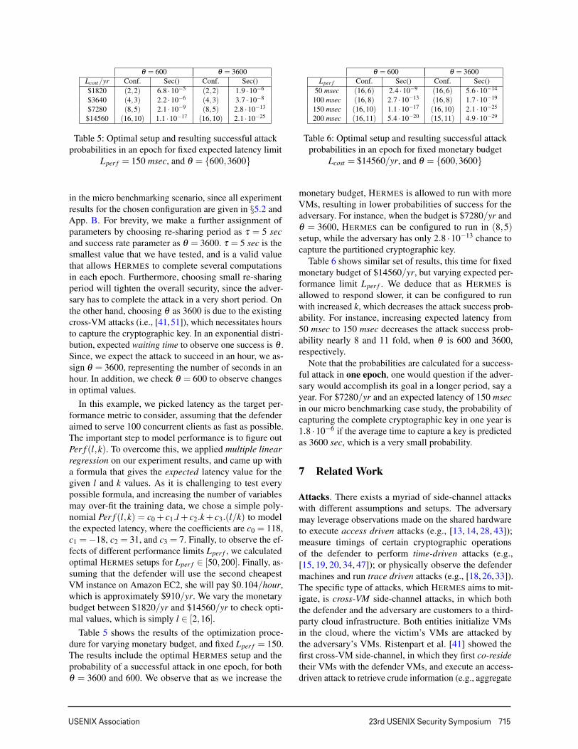
Table 5: Optimal setup and resulting successful attackprobabilities in an epoch for fixed expected latency limit
Lper f = 150 msec, and θ = {600,3600}
in the micro benchmarking scenario, since all experimentresults for the chosen configuration are given in §5.2 andApp. B. For brevity, we make a further assignment ofparameters by choosing re-sharing period as τ = 5 secand success rate parameter as θ = 3600. τ = 5 sec is thesmallest value that we have tested, and is a valid valuethat allows HERMES to complete several computationsin each epoch. Furthermore, choosing small re-sharingperiod will tighten the overall security, since the adver-sary has to complete the attack in a very short period. Onthe other hand, choosing θ as 3600 is due to the existingcross-VM attacks (i.e., [41,51]), which necessitates hoursto capture the cryptographic key. In an exponential distri-bution, expected waiting time to observe one success is θ .Since, we expect the attack to succeed in an hour, we as-sign θ = 3600, representing the number of seconds in anhour. In addition, we check θ = 600 to observe changesin optimal values.
In this example, we picked latency as the target per-formance metric to consider, assuming that the defenderaimed to serve 100 concurrent clients as fast as possible.The important step to model performance is to figure outPer f (l,k). To overcome this, we applied multiple linearregression on our experiment results, and came up witha formula that gives the expected latency value for thegiven l and k values. As it is challenging to test everypossible formula, and increasing the number of variablesmay over-fit the training data, we chose a simple poly-nomial Per f (l,k) = c0 + c1.l + c2.k+ c3.(l/k) to modelthe expected latency, where the coefficients are c0 = 118,c1 =−18, c2 = 31, and c3 = 7. Finally, to observe the ef-fects of different performance limits Lper f , we calculatedoptimal HERMES setups for Lper f ∈ [50,200]. Finally, as-suming that the defender will use the second cheapestVM instance on Amazon EC2, she will pay $0.104/hour,which is approximately $910/yr. We vary the monetarybudget between $1820/yr and $14560/yr to check opti-mal values, which is simply l ∈ [2,16].
Table 5 shows the results of the optimization proce-dure for varying monetary budget, and fixed Lper f = 150.The results include the optimal HERMES setup and theprobability of a successful attack in one epoch, for bothθ = 3600 and 600. We observe that as we increase the
θ = 600 θ = 3600Lper f Conf. Sec() Conf. Sec()
50 msec (16,6) 2.4 ·10−9 (16,6) 5.6 ·10−14
100 msec (16,8) 2.7 ·10−13 (16,8) 1.7 ·10−19
150 msec (16,10) 1.1 ·10−17 (16,10) 2.1 ·10−25
200 msec (16,11) 5.4 ·10−20 (15,11) 4.9 ·10−29
Table 6: Optimal setup and resulting successful attackprobabilities in an epoch for fixed monetary budget
Lcost = $14560/yr, and θ = {600,3600}
monetary budget, HERMES is allowed to run with moreVMs, resulting in lower probabilities of success for theadversary. For instance, when the budget is $7280/yr andθ = 3600, HERMES can be configured to run in (8,5)setup, while the adversary has only 2.8 ·10−13 chance tocapture the partitioned cryptographic key.
Table 6 shows similar set of results, this time for fixedmonetary budget of $14560/yr, but varying expected per-formance limit Lper f . We deduce that as HERMES isallowed to respond slower, it can be configured to runwith increased k, which decreases the attack success prob-ability. For instance, increasing expected latency from50 msec to 150 msec decreases the attack success prob-ability nearly 8 and 11 fold, when θ is 600 and 3600,respectively.
Note that the probabilities are calculated for a success-ful attack in one epoch, one would question if the adver-sary would accomplish its goal in a longer period, say ayear. For $7280/yr and an expected latency of 150 msecin our micro benchmarking case study, the probability ofcapturing the complete cryptographic key in one year is1.8 ·10−6 if the average time to capture a key is predictedas 3600 sec, which is a very small probability.
7 Related Work
Attacks. There exists a myriad of side-channel attackswith different assumptions and setups. The adversarymay leverage observations made on the shared hardwareto execute access driven attacks (e.g., [13, 14, 28, 43]);measure timings of certain cryptographic operationsof the defender to perform time-driven attacks (e.g.,[15, 19, 20, 34, 47]); or physically observe the defendermachines and run trace driven attacks (e.g., [18, 26, 33]).The specific type of attacks, which HERMES aims to mit-igate, is cross-VM side-channel attacks, in which boththe defender and the adversary are customers to a third-party cloud infrastructure. Both entities initialize VMsin the cloud, where the victim’s VMs are attacked bythe adversary’s VMs. Ristenpart et al. [41] showed thefirst cross-VM side-channel, in which they first co-residetheir VMs with the defender VMs, and execute an access-driven attack to retrieve crude information (e.g., aggregate
716 23rd USENIX Security Symposium USENIX Association
cache usage). In another work, though not for adversar-ial purposes, Zhang et al. [50] present HomeAlone thatperforms a co-residency check between two VMs usingclassifiers on cache timing. In another attack, Zhang et al.push it one step further, and extract an ElGamal privatekey using cross-VM attacks [51]. Those works showedthat VMs in public cloud infrastructures are vulnerableto side-channel attacks, and protection mechanisms areneeded to secure private information.
Prevention. Among the variety of side-channel preven-tion techniques, the most popular ones are randomization-based approaches. MIST is one of such examples, inwhich the square-and-multiply method is extended withan additional division by a randomly chosen number [38,45]. Other approaches include adding random noise be-tween squaring and multiplying operations, or applyingalways-multiply techniques. To countermeasure thoseside-channel prevention techniques, Karlof et al. promotesHidden Markov Model based cryptanalysis as a powerfultool [30]. On the other hand, Witteman et al. shows a tracedriven side-channel attack to break down always-multiplytechnique and message binding in RSA [49]. Althoughthe latter is trace driven, those two works show that evenrandomization based side-channel prevention approachescould have vulnerabilities that can be used by differenttypes of adversaries.
There exist several works that aim to prevent side-channel attacks in public clouds. HomeAlone [50] usesco-residency checks to see if a VM is physically isolatedfrom any other VM, and to achieve maximum physicalisolation. Our work aims to prevent the leakage of privatekeys even if the adversary co-resides with the defender,whereas they aim to prevent access-driven side-channel at-tacks by assuring physical isolation. In HyperSafe, Wangand Jiang aim to provide hypervisor integrity throughoutthe execution [46]. We assume that the cloud provider andits infrastructure (including the hypervisor) are trusted.Other prevention mechanisms include [17], which aimsto prevent side-channel attacks that use communicationtraffic; StealthMem that hides memory access patternsto protect private information [32]. Compared to theseworks, HERMES is applicable to any type of cross-VMattacks against cryptographic keys.
8 Conclusion
In this paper, we present HERMES, a novel system to pro-tect cryptographic keys in cloud VMs. The key idea is toperiodically partition a cryptographic key using additiveor Shamir secret sharing. With two different case studies,we show that the overhead can be as low as 1%. Withsuch small overhead in an average request, cryptographickeys become more leakage-resilient against any adversary.
Furthermore, we model the problem of finding optimalparameters for the given monetary and performance con-straints, which minimizes the security risk. Using our for-mal model, the defender can calculate the probability of asuccessful attack, and take precautions (e.g., increase thenumber of VMs, decrease epoch length). As a proof-of-concept, the current implementation of HERMES mainlyfocuses on the protection of the RSA private key, whichis widely used in many daily web site and mail servercommunications. However, there exists a myriad of workson threshold signature schemes for different cryptosys-tems, (e.g., [21, 23, 27, 35, 36]), which may be applicableto HERMES with slight modifications.
9 Acknowledgement
We thank the anonymous reviewers for their insight-ful comments. This work was partially supported byAir Force Office of Scientific Research FA9550-12-1-0082 and FA9550-14-1-0119, National Institutes ofHealth Grants 1R0-1LM009989 and 1R01HG006844,National Science Foundation (NSF) Grants Career-CNS-0845803, CNS-0964350, CNS-1016343, CNS-1111529,CNS-1228198 and Army Research Office Grant W911NF-12-1-0558.
References[1] Us web statistics released for may 2012: which sites
dominate, and where do we go for online news?http://www.theguardian.com/news/datablog/2012/jun/22/website-visitor-statistics-nielsen-may-2012-google, 2012.
[2] Internet 2012 in numbers. http://royal.pingdom.com/2013/01/16/internet-2012-in-numbers/, 2013.
[3] Public, private and hybrid clouds when, why and how they arereally used. Tech. rep., Summary report, Neovise, 2013.
[4] Amazon elastic compute cloud.http://aws.amazon.com/pricing/ec2/, 2014.
[5] Apache http server benchmarking tool.http://httpd.apache.org/docs/2.4/programs/ab.html, 2014.
[6] The apache jmeter desktop application. http://jmeter.apache.org/,2014.
[7] Apache: The number one http server on the internet.http://httpd.apache.org/, 2014.
[8] Dovecot, an open source imap and pop3 email server.http://www.dovecot.org, 2014.
[9] Google compute engine. https://cloud.google.com/products/compute-engine, 2014.
[10] The openssl project. http://www.openssl.org, 2014.
[11] The postfix home page. http://www.postfix.org/start.html, 2014.
[12] Windows azure. http://www.windowsazure.com/en-us/, 2014.
[13] ACIICMEZ, O., BRUMLEY, B. B., AND GRABHER, P. New resultson instruction cache attacks. In Cryptographic Hardware andEmbedded Systems, CHES 2010. Springer, 2010, pp. 110–124.
USENIX Association 23rd USENIX Security Symposium 717
[14] ACIICMEZ, O., KOC, C. K., AND SEIFERT, J.-P. On the powerof simple branch prediction analysis. In Proceedings of the 2ndACM symposium on Information, computer and communicationssecurity (2007), ACM, pp. 312–320.
[15] ACIICMEZ, O., SCHINDLER, W., AND KOC, C. K. Cache basedremote timing attack on the aes. In Topics in Cryptology–CT-RSA2007. Springer, 2006, pp. 271–286.
[16] ALLEN, C., AND DIERKS, T. The tls protocol version 1.0.
[17] BACKES, M., DOYCHEV, G., AND KOPF, B. Preventing side-channel leaks in web traffic: A formal approach. In NDSS (2013).
[18] BERTONI, G., ZACCARIA, V., BREVEGLIERI, L., MONCHIERO,M., AND PALERMO, G. Aes power attack based on induced cachemiss and countermeasure. In Information Technology: Codingand Computing, 2005. ITCC 2005. International Conference on(2005), vol. 1, IEEE, pp. 586–591.
[19] BRUMLEY, B. B., AND TUVERI, N. Remote timing attacks arestill practical. In Computer Security–ESORICS 2011. Springer,2011, pp. 355–371.
[20] BRUMLEY, D., AND BONEH, D. Remote timing attacks are prac-tical. Computer Networks 48, 5 (2005), 701–716.
[21] DESMEDT, Y. Some recent research aspects of threshold cryptog-raphy. In Information Security. Springer, 1998, pp. 158–173.
[22] DIFFIE, W., AND HELLMAN, M. New directions in cryptography.Information Theory, IEEE Transactions on 22, 6 (1976), 644–654.
[23] FOUQUE, P.-A., AND POINTCHEVAL, D. Threshold cryptosys-tems secure against chosen-ciphertext attacks. In Advances inCryptologyASIACRYPT 2001. Springer, 2001, pp. 351–368.
[24] FRANKEL, Y. A practical protocol for large group oriented net-works. In Advances in Cryptology EUROCRYPT 1989 (1990),Springer, pp. 56–61.
[25] FREIER, A. The ssl protocol version 3.0.http://ci.nii.ac.jp/naid/10015295976/en/, 1996.
[26] GANDOLFI, K., MOURTEL, C., AND OLIVIER, F. Electromag-netic analysis: Concrete results. In Cryptographic Hardware andEmbedded Systems CHES 2001 (2001), Springer, pp. 251–261.
[27] GENNARO, R., JARECKI, S., KRAWCZYK, H., AND RABIN, T.Robust threshold dss signatures. In Advances in CryptologyEU-ROCRYPT96 (1996), Springer, pp. 354–371.
[28] GULLASCH, D., BANGERTER, E., AND KRENN, S. Cache games–bringing access-based cache attacks on aes to practice. In Securityand Privacy (SP), 2011 IEEE Symposium on (2011), IEEE, pp. 490–505.
[29] HICKMAN, K., AND ELGAMAL, T. The ssl protocol. NetscapeCommunications Corp 501 (1995).
[30] KARLOF, C., AND WAGNER, D. Hidden markov model cryptanal-ysis. In Cryptographic Hardware and Embedded Systems–CHES2003: 5th International Workshop, Cologne, Germany, September8-10, 2003, Proceedings (2003), vol. 5, Springer, p. 17.
[31] KELLER, E., AND REXFORD, J. The platform as a service modelfor networking. In Proceedings of the 2010 internet networkmanagement conference on Research on enterprise networking(2010), vol. 4, USENIX Association.
[32] KIM, T., PEINADO, M., AND MAINAR-RUIZ, G. Stealthmem:system-level protection against cache-based side channel attacksin the cloud. In Proceedings of the 21st USENIX conference onSecurity symposium (2012), USENIX Association, pp. 11–11.
[33] KOCHER, P., JAFFE, J., AND JUN, B. Differential power analy-sis. In Advances in Cryptology CRYPTO 1999 (1999), Springer,pp. 388–397.
[34] KOCHER, P. C. Timing attacks on implementations of diffie-hellman, rsa, dss, and other systems. In Advances in CryptologyCRYPTO 1996 (1996), Springer, pp. 104–113.
[35] KUROSAWA, K. New eigamal type threshold digital signa-ture scheme. IEICE transactions on fundamentals of electronics,communications and computer sciences 79, 1 (1996), 86–93.
[36] LANGFORD, S. K. Threshold dss signatures without a trustedparty. In Advances in CryptologyCRYPT095. Springer, 1995,pp. 397–409.
[37] OPPLIGER, R. SSL and TLS: Theory and Practice. Artech House,2009.
[38] OSWALD, E., AND AIGNER, M. Randomized addition-subtractionchains as a countermeasure against power attacks. In Crypto-graphic Hardware and Embedded SystemsCHES 2001 (2001),Springer, pp. 39–50.
[39] OWENS, R., AND WANG, W. Non-interactive os fingerprintingthrough memory de-duplication technique in virtual machines.In Performance Computing and Communications Conference(IPCCC), 2011 IEEE 30th International (2011), IEEE, pp. 1–8.
[40] PRODAN, R., AND OSTERMANN, S. A survey and taxonomy ofinfrastructure as a service and web hosting cloud providers. InGrid Computing, 2009 10th IEEE/ACM International Conferenceon (2009), IEEE, pp. 17–25.
[41] RISTENPART, T., TROMER, E., SHACHAM, H., AND SAVAGE,S. Hey, you, get off of my cloud: exploring information leakagein third-party compute clouds. In Proceedings of the 16th ACMconference on Computer and communications security (2009),ACM, pp. 199–212.
[42] SHOUP, V. Practical threshold signatures. In Advances in Cryptol-ogy EUROCRYPT 2000 (2000), Springer, pp. 207–220.
[43] TROMER, E., OSVIK, D. A., AND SHAMIR, A. Efficient cacheattacks on aes, and countermeasures. Journal of Cryptology 23, 1(2010), 37–71.
[44] VAQUERO, L. M., RODERO-MERINO, L., CACERES, J., ANDLINDNER, M. A break in the clouds: towards a cloud definition.ACM SIGCOMM Computer Communication Review 39, 1 (2008),50–55.
[45] WALTER, C. D. Mist: An efficient, randomized exponentiationalgorithm for resisting power analysis. In Topics in CryptologyCT-RSA 2002. Springer, 2002, pp. 53–66.
[46] WANG, Z., AND JIANG, X. Hypersafe: A lightweight approach toprovide lifetime hypervisor control-flow integrity. In Security andPrivacy (SP), 2010 IEEE Symposium on (2010), IEEE, pp. 380–395.
[47] WEISS, M., HEINZ, B., AND STUMPF, F. A cache timing attackon aes in virtualization environments. In Financial Cryptographyand Data Security. Springer, 2012, pp. 314–328.
[48] WINKLER, V. Cloud computing: Cloud security concerns. Tech.rep., 2011.
[49] WITTEMAN, M. F., VAN WOUDENBERG, J. G., AND MENARINI,F. Defeating rsa multiply-always and message blinding counter-measures. In Topics in Cryptology–CT-RSA 2011. Springer, 2011,pp. 77–88.
[50] ZHANG, Y., JUELS, A., OPREA, A., AND REITER, M. K. Home-alone: Co-residency detection in the cloud via side-channel anal-ysis. In Security and Privacy (SP), 2011 IEEE Symposium on(2011), IEEE, pp. 313–328.
[51] ZHANG, Y., JUELS, A., REITER, M. K., AND RISTENPART, T.Cross-vm side channels and their use to extract private keys. InProceedings of the 2012 ACM conference on Computer and com-munications security (2012), ACM, pp. 305–316.
718 23rd USENIX Security Symposium USENIX Association
Setup(9,2) (9,3) (9,4) (9,5) (9,6) (9,7) (9,8) (9,9)
1 ClientsTotal 9.58 10.70 11.53 15.88 13.93 13.97 14.13 14.05Network 4.76 4.49 4.85 5.30 5.01 4.84 2.45 1.07Combine 0.55 1.44 1.18 1.65 1.77 1.65 2.75 2.00
10 ClientsTotal 19.26 21.29 24.14 31.43 32.81 39.67 46.73 50.64Network 9.26 10.84 12.87 15.85 14.55 22.92 23.74 18.11Combine 1.33 1.51 1.68 2.07 2.61 2.83 2.76 2.58
100 ClientsTotal 58.08 68.32 91.87 144.08 164.54 209.26 247.54 257.03Network 25.26 37.91 51.19 98.69 108.02 101.33 111.37 98.71Combine 1.15 1.64 2.01 2.24 2.56 2.14 2.81 2.81
Table 7: Average Connection, Network, and Combining Time Spent for Fixed l = 9 in milliseconds
Setup(3,3) (4,3) (5,3) (6,3) (7,3) (8,3) (9,3) (10,3)
1 ClientsTotal 10.4 12.98 12.04 11.96 13.33 11.57 10.70 12.27Network 2.82 6.57 5.11 5.04 5.28 4.92 4.49 5.14Combine 1.76 1.46 1.66 1.51 1.90 1.49 1.44 0.56
10 ClientsTotal 37.85 35.85 29.35 24.22 24.31 21.66 21.29 23.22Network 21.67 21.81 15.76 12.43 11.53 10.56 10.84 10.15Combine 2.05 2.02 1.97 1.69 1.71 1.57 1.51 1.07
100 ClientsTotal 178.14 209.99 146.54 99.47 86.62 79.72 68.32 71.07Network 113.36 158.35 112.46 67.47 61.25 51.57 37.91 25.27Combine 2.14 2.49 2.00 1.85 1.90 1.65 1.64 1.62
Table 8: Average Connection, Network, and Combining Time Spent for Fixed k = 3 in milliseconds
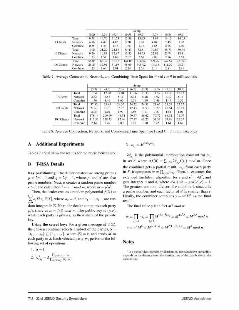
A Additional Experiments
Tables 7 and 8 show the results for the micro benchmark.
B T-RSA Details
Key partitioning: The dealer creates two strong primesp = 2p′ + 1 and q = 2q′ + 1, where p′ and q′ are alsoprime numbers. Next, it creates a random prime numbere > l, and calculates d = e−1 mod m, where m = p′q′.
Then, the dealer creates a random polynomial f (X) =k−1∑
i=0aiXi ∈ Z[X ], where a0 = d, and a1, . . . ,ak−1 are ran-
dom integers in Z. Next, the dealer computes each partypi’s share as si = f (i) mod m. The public key is (n,e),while each party is given si as their share of the privatekey.
Using the secret key: For a given message M ∈ Z∗n,
the chosen combiner selects a subset of the parties, S ={i1, . . . , ik} ⊆ {1, . . . , l}, where |S| = k, and sends M toeach party in S. Each selected party pi j performs the fol-lowing set of operations:
1. ∆ = l!
2. λ S0,i j
= ∆∏ix∈S\{i j} −ix
∏ix∈S\{i j} (i j−ix)
3. wi j = M4∆si j λ0,i j
λ S0,i j
is the polynomial interpolation constant for pi j
in set S, where ∆ f (0) ≡ ∑i j∈S λ S0,i j
f (i j) mod m. Once
the combiner gets a partial result, wi j , from each partyin S, it computes w = ∏i j∈S wi j . Then, it executes theextended Euclidean algorithm for e and e′ = 4∆2, andgets integers a and b, where e′a+ eb = gcd(e′,e) = 1.The greatest common divisor of e and e′ is 1, since e isa prime number, and each factor of e′ is smaller than e.Finally, the combiner computes y = waMb as the finalresult.
The final value y is in fact Md mod n:
w ≡ ∏i j∈S
wi j ≡ ∏i j∈S
M4∆si j λ0,i j ≡ M4∆2d ≡ Me′d mod n
y ≡ waMb ≡ Mae′d+b ≡ Md(1−eb)+b ≡ Md mod n
Notes
1In a memoryless probability distribution, the cumulative probabilitydepends on the distance from the starting time of the distribution to thecurrent time.