presto power
TRANSCRIPT

Alessandro ARNULFO R&D Application Engineer
PRESTO_POWER
2
of
21
Now PRESTO is able to take into account noise
propagation in any shape copper area.
PRESTO_POWER is an high performance
software tool to simulate high speed PCB taking
into account EMC phenomena as bouncing on
power plane.
PRESTO POWER

3
of
21
CAD
Extraction
Sim. Set Up
Creation of
SPRINT netlist
SPRINT
Display
Results
SUBCIRCUITS of each
copper area are linked to
the other circuit elements.
Extraction of
copper areas and
planes shape
Possibility to model
planes or not
PRESTO ver. 3.2 New features implemented
in PRESTO_POWER
PRESTO_POWER flow

4
of
21
• Power plane modelling
- ground bouncing (noise propagation)
- filtering (bypass C placing optimisation )
• Gridding algorithm
•Conclusion
NEXT STEPS

5
of
21
Power planes modelling is necessary to
simulate effects such as:
• noise propagation and ground bounce
influence on signals
• simulation of power plane filtering effect
• optimisation of bypass capacitors
placement on PCB
POWER PLANES MODELLING

7
of
21
Power planes modelling is
necessary to simulate the
noise propagation and
ground bounce effect on
signals
NOISE PROPAGATION
& GROUND BOUNCE

8
of
21
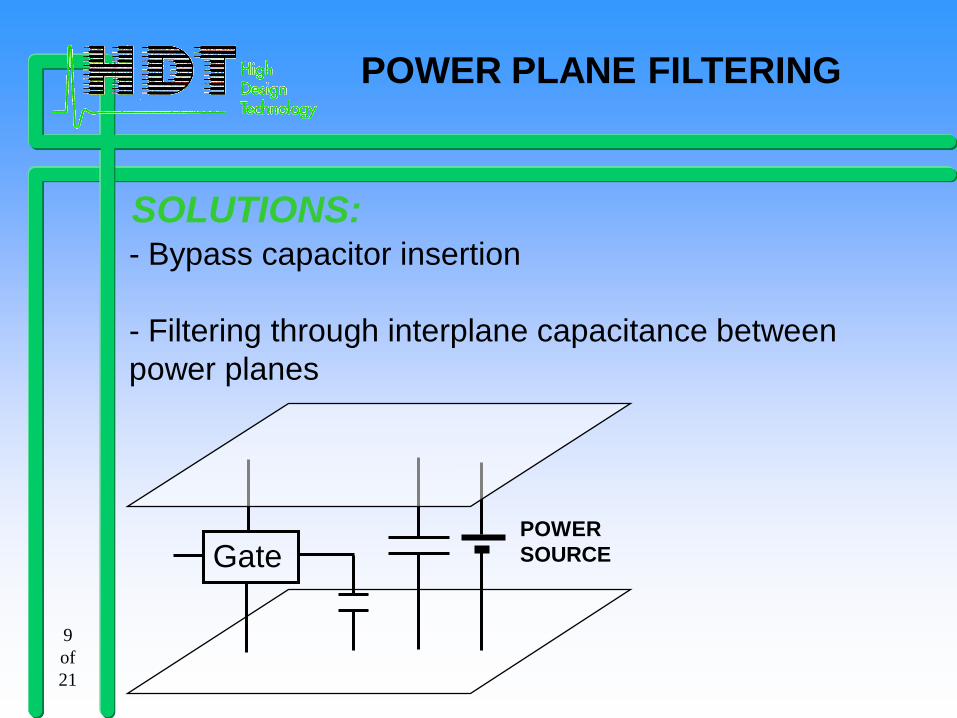
Gate
Very large
power
supply
inductance
Power supply
input drops to zero
The gate may no
longer work or
break into
oscillation
POWER PLANE FILTERING
POWER
SOURCE
9
of
21
- Bypass capacitor insertion
- Filtering through interplane capacitance between
power planes
SOLUTIONS:
Gate POWER
SOURCE
POWER PLANE FILTERING

10
of
21
WHAT IF ANALISY FOR
BYPASS CAPACITOR

11
of
21
Power planes modelling is
necessary to:
• simulate the power planes
filtering effect
• optimise bypass capacitors
placement on PCB
POWER PLANE FILTERING

12
of
21
The model, used to describe the area, is a grid of
losses transmission lines. This requires a mesh
with square cells. This choice guarantees the
same propagation delay for all transmission line.
GRID OF LOSSY
TRASMISSION LINE
UNIFORM Td

13
of
21
Flexibility:
each metal area can have a
different, optimised grid step
Parameters related to the grid step:
• Tstep : minimum time resolution
• max N_row : user-defined grid row limits
• max N_col : user-defined grid column limits
MESH GENERATOR
5V
3.3V

14
of
21
Propagation speed (cross-section of PCB)
Tstep (set up in simulation)
dstep (spatial resolution)
Single cell must
have dimensions
multiple of dstep
micro-grid
dstep
GRID CHOICE ANALISY

15
of
21
Result after the
meshing algorithm.
The rectangular
boundary is gridded
with a regular mesh.
0% 88% 100% 0%
AN EXAMPLE OF GRIDDED AREA
ZOOM
IN

16
of
21
POWER PLANE MODEL (ZOOM)
grid on which is built
TL network
grid_step dstep
micro-grid linked to tstep

17
of
21
COPPER AREA GRIDDED
Completely filled
Partially filled

18
of
21
User can choose to model:
• POWER NET: PLANES SPLITTED PLANES
• SIGNAL NET
Areas connections topology:
• SEGMENT - AREA
• VIA - AREA
• PIN - AREA
POWER PLANES MODELLING

19
of
21
The user can choose to model or
not signal and/or power areas
Gridding settings
AREAS SETTING
USER INTERFACE

20
of
21
POWER PLANES MODELLING
FOR MERITA PROJECT
When several gates switch
simultaneously, a large amount of noise
is injected into power and ground pins
The power planes model is used to
evaluate noise voltage on power and
ground planes.

21
of
21
CONCLUSION
MOST IMPORTANT ACHIEVEMENT
Copper areas modelling integration in
PRESTO
FUTURE STEP
Taking into account coupling effects
between copper area