pressure - ifpusa.com switch supplemental... · it must be remembered that, although a pressure...
TRANSCRIPT
Pressure
1
Supplemental Guide Pressure Switch Products
STEP 1 - SERVICE LIFE OF THE SWITCH Expected service life is the first consideration to be made in selecting a pressure switch, regardless of the pressure or sensitivity desired. If the service life (the number of cycles the switch is expected to operate) is one million or less, use of either a bourdon tube or diaphragm switch is indicated. If a service life of more than one million cycles is desired, a piston switch should be used. An exception to this rule may be made when pressure change in a system is very slight (20% or less, of the adjustable range). Under such conditions a bourdon tube or diaphragm switch can be used up to 2.5 million cycles before metal fatigue.
A second consideration in choosing a pressure switch is the speed of cycling, regardless of the service life. If a switch is expected to cycle more than once every three seconds, a piston type switch should be specified. The metal of any bourdon tube or diaphragm acts as a spring which will heat and fatigue in extremely fast cycling operations, thus shortening the life of the switch.
The media to be controlled must always be considered when selecting a pressure switch and, to simplify selection, wetted materials for each type of switch are noted on applicable catalog pages.
STEP 2 - PROOF PRESSURES Choice of the type of pressure switch to be used - diaphragm, bourdon tube or piston - also must be governed by the proof pressure to which it will be subjected. (Proof pressure is the highest surge pressure that will ever be experienced in a system.) It must be remembered that, although a pressure gauge may register a constant operating pressure, there may be surges going through a system that are dampened out by the orifice in the gauge. Diaphragm and bourdon tube pressure switches are extremely sensitive and would be affected by those surges. Barksdale diaphragm switches are available in an adjustable range from vacuum to 150 psi with proof pressures to 300 psi. Barksdale bourdon tube switches are adjustable to 18,000 psi with proof pressures of 24,000 psi. Barksdale piston switches have an adjustable range to 12,000 psi with a proof pressure of 20,000 psi.
STEP 3 - FUNCTION OF THE SWITCH The function of the switch is another determining factor in making a selection. Three types of Barksdale pressure switches, based on function, are described below: (1) Single setting pressure switches sense a single pressure source and open or close a single electrical circuit by means of one snap action electrical switch. (2) Pressure difference switches sense a change in relationship between two variable contained pressures and open or close a single electrical circuit by means of one snap action electrical switch.
How to Select a Pressure Switch for your Application
ACCURACY
LIFE
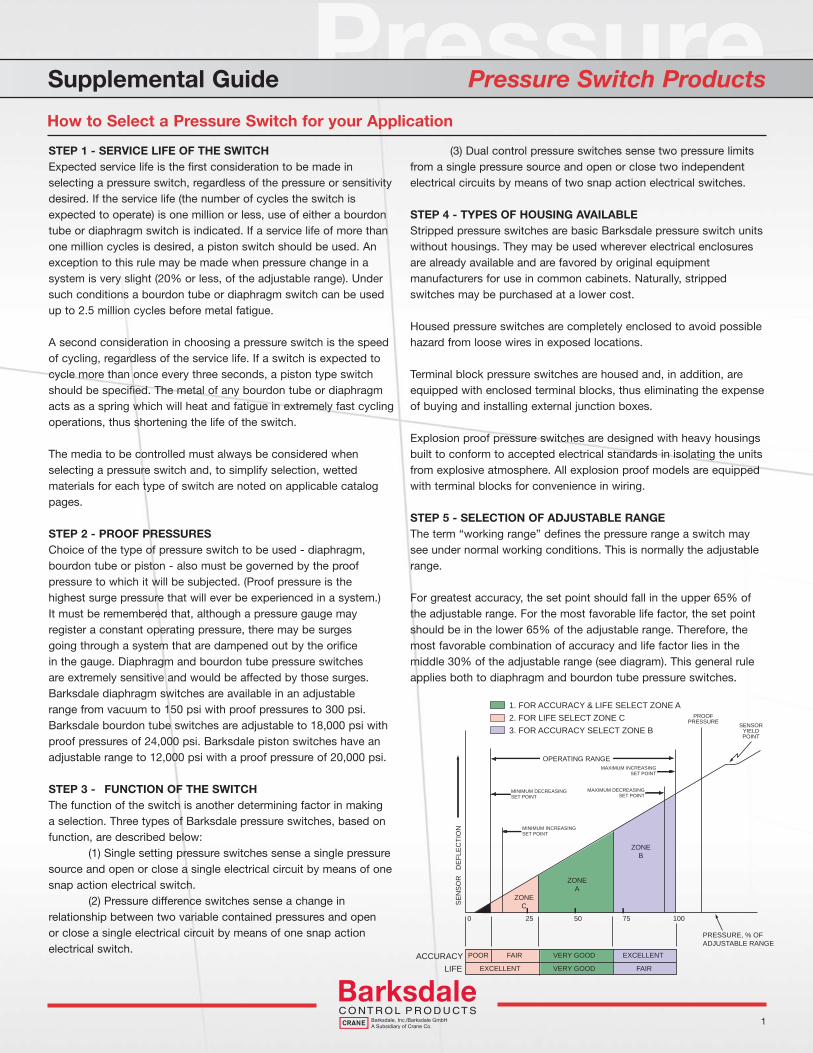
POOR FAIR VERY GOOD EXCELLENT
EXCELLENT VERY GOOD FAIR
PRESSURE, % OF
ADJUSTABLE RANGE
ZONE
C
ZONE
A
ZONE
B
0 25 50 75 100
MINIMUM DECREASINGSET POINT
MAXIMUM INCREASINGSET POINT
MINIMUM INCREASINGSET POINT
MAXIMUM DECREASINGSET POINT
OPERATING RANGE
SE
NS
OR
D
EF
LE
CT
ION
1. FOR ACCURACY & LIFE SELECT ZONE A
2. FOR LIFE SELECT ZONE C
3. FOR ACCURACY SELECT ZONE B
PROOFPRESSURE
SENSORYIELDPOINT
(3) Dual control pressure switches sense two pressure limits from a single pressure source and open or close two independent electrical circuits by means of two snap action electrical switches.
STEP 4 - TYPES OF HOUSING AVAILABLE Stripped pressure switches are basic Barksdale pressure switch units without housings. They may be used wherever electrical enclosures are already available and are favored by original equipment manufacturers for use in common cabinets. Naturally, stripped switches may be purchased at a lower cost.
Housed pressure switches are completely enclosed to avoid possible hazard from loose wires in exposed locations.
Terminal block pressure switches are housed and, in addition, are equipped with enclosed terminal blocks, thus eliminating the expense of buying and installing external junction boxes.
Explosion proof pressure switches are designed with heavy housings built to conform to accepted electrical standards in isolating the units from explosive atmosphere. All explosion proof models are equipped with terminal blocks for convenience in wiring.
STEP 5 - SELECTION OF ADJUSTABLE RANGE The term “working range” defines the pressure range a switch may see under normal working conditions. This is normally the adjustable range.
For greatest accuracy, the set point should fall in the upper 65% of the adjustable range. For the most favorable life factor, the set point should be in the lower 65% of the adjustable range. Therefore, the most favorable combination of accuracy and life factor lies in the middle 30% of the adjustable range (see diagram). This general rule applies both to diaphragm and bourdon tube pressure switches.

2
General Operating, Engineering & Service Data
Supplemental Guide Pressure Switch Products
Steam Service
Only diaphragm and bourdon tube switches are suitable for steam service. Install pressure switch with pressure fi tting up; preferably with two or three 4” to 8” coiling loops in the pressure line to serve as heat exchangers and to form a static water head as buffer to the steam temperature. Dia-Seal type switches may be used if fi ttings are stainless steel, polysulfone or nickel-plated.
Chemical Protectors
Many Barksdale pressure switches can be used in conjunction with liquid fi lled chemical protectors: Contact factory.1. The DIT, D2T, DIH, D2H, DIX, D2X-H18 or -H18SS switches will have an increase in actuation value (differential) of approximately 50%.2. If a capillary system is used, a lag time will be introduced unless the pressure change is very gradual.3. Only capillary-type connections can be furnished on pressure difference type switches.4. Piston type switches, models 9048, T9048, C9612, 9672, C9622, TC9622, 9653, 9673 and diaphragm switches with proof pressure ratings of 3 psi and 10 psi (-2 and -3 models) CANNOT be used with chemical protectors. Econ-O-Trols must have impregnated or polysulfone fi ttings.5. Vacuum service greater than 20” hg. (gauge) is not recommended. For greater vacuum, consult factory with all details of the application given.
Life Expectancy
The same factors governing the life of gauges and other instruments, using bourdon tube or diaphragm sensing elements, apply to pressure switches.If with each operating cycle the sensing element must fl ex over the entire operating range for which it was designed, or whether it fl exes only over a small portion of that range considerably affects the life expectancy of the unit.The second factor to speed up metal fatigue of the tube or diaphragm is the speed with which it must repeat the fl exing cycles. At normal fl exing rate (less than 25 cycles per minute) you may therefore fi nd the following variance in the same type of sensing element:At full range fl exing up to 1,000,000 cycles depending on thickness of diaphragm. The thinner the material, the longer the life. At 50% of its fl exing range up to 3,500,000 cycles (see above). At 10 to 20% of its fl exing range up to 5,000,000 cycles (see above).
Corrosive Environments
Barksdale housed and explosion proof pressure switches intended for use in hostile and/or corrosive environments can be painted with green epoxy paint (color per Federal Standard 595A #24300). The complete switch is painted after assembly and test at Barksdale. For best results, exposed metal surfaces must be touched up with epoxy paint after installation.
See Barksdale’s Standard Conditions of Sale • Specifications are subject to modification at any time • Bulletin #S0092-A • 09/07 • ©2007 • Printed in the U.S.A.
3211 Fruitland Avenue • Los Angeles, CA 90058 • 800-835-1060 • Fax: 323-589-3463 • www.barksdale.com
Pressure
3
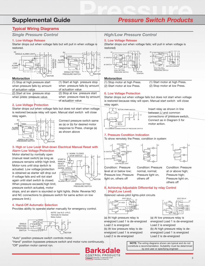
Supplemental Guide Pressure Switch ProductsTypical Wiring Diagrams
1. Low-Voltage ReleaseStarter drops out when voltage fails but will pull in when voltage is restored.
Motoraction(1) Stop at high pressure start when pressure falls by amount of actuation value(2) Start at low pressure stop when press. pressure value.
(1) Start at high pressure stop when pressure falls by amount of actuation value(2) Stop at low pressure start when pressure rises by amount of actuation value
2. Low-Voltage ProtectionStarter drops out when voltage fails but does not start when voltage is restored because relay will open. Manual start switch will close relay again.
Connect pressure switch same as (a) or (b) for desired motor response to Press. change (a) as shown above
3. High or Low Level Shut-down Electrical Manual Reset with Alarm-Low Voltage ProtectionMotor started by normally open (manual reset switch) as long as pressure remains within high limit. Motor runs until stop switch is actuated. Low voltage protection is obtained as starter will drop out if voltage fails and will not start again until start switch is closed. When pressure exceeds high limit, pressure switch actuates, motor stops, and an alarm is sounded or light lights. (Note: Reverse NO and NC connections to pressure switch for same action on low pressure limit.)
4. Hand-Off Automatic SelectionProvides ability to operate starter manually for emergency control.
“Auto” position pressure switch controls motor.“Hand” position bypasses pressure switch and motor runs continuously.“Off” position motor cannot run.
Single Pressure Control5. Low Voltage Release(Starter drops out when voltage fails; will pull in when voltage is restored)
Motoraction(1) Stop motor at high Press. (2) Start motor at low Press.
6. Low Voltage ProtectionStarter drops out when voltage fails but does not start when voltage is restored because relay will open. Manual start switch will close relay again.
7. Pressure Condition IndicationTo show remotely the Press. condition in system
8. Achieving Adjustable Differential by relay Control (High/Low Level)Solenoid valves-pilot lights-pilot circuits
(a) At high pressure relay is energized Load 1 is de-energizedLoad 2 is energized(b) At low pressure relay is de-energized Load 1 is energizedLoad 2 is de-energized
High/Low Pressure Control
(1) Start motor at high Press. (2) Stop motor at low Press.
Insert relay as shown in line between Ll and common connections of pressure switch. Connect as in Diagram 5 for motor action.
Condition: Pressure level at or below low; Pressure low; Pressure light on, others off
Condition: Pressure normal, normal; Pressure light on, others off
Condition: Pressure at or above high; Pressure high; Pressure light on, others off
(a) At low pressure relay is energized Load 1 is de-energizedLoad 2 is energized(b) At high pressure relay is de-energized Load 1 is energizedLoad 2 is de-energized
NOTE: The wiring diagrams shown are typical and do not constitute a recommendation. Suitability must be determined
by end user or specifying engineer

See Barksdale’s Standard Conditions of Sale • Specifications are subject to modification at any time • Bulletin #S0092-A • 09/07 • ©2007 • Printed in the U.S.A.4
3211 Fruitland Avenue • Los Angeles, CA 90058 • 800-835-1060 • Fax: 323-589-3463 • www.barksdale.com
Supplemental Guide Pressure Switch ProductsConversion Tables
in/H20 1 2 3 4 5 6 7 8 9 10 11 12 13 14 15 16 17 18 19 20 21 22 23 24 25 26 27 28 29 30 31 32 33 34 35 36 37 38 39 40 41 42 43 44 45 46 47 48 49 50 51 52 53 54 55 56 57 58 59 60 61 62 63 64 65 66 67 68 69 70 71 72 73 74 75 76 77 78 79 80 81 82 83 84 85 86 87 88 89 90 91 92 93 94 95 96 97 98 99 100
psi .04 .07 .11 .15 .18 .22 .25 .29 .32 .36 .40 .43 .47 .50 .54 .58 .61 .65 .68 .72 .76 .79 .83 .87 .90 .94 .97 1.01 1.05 1.08 1.12 1.15 1.19 1.23 1.26 1.30 1.33 1.37 1.41 1.44 1.48 1.50 1.55 1.59 1.62 1.66 1.69 1.72 1.76 1.80 1.84 1.87 1.91 1.95 1.98 2.02 2.05 2.09 2.13 2.16 2.20 2.23 2.27 2.31 2.34 2.38 2.41 2.44 2.48 2.52 2.55 2.59 2.63 2.66 2.70 2.73 2.77 2.80 2.84 2.88 2.91 2.95 2.98 3.02 3.06 3.09 3.13 3.16 3.20 3.24 3.27 3.31 3.34 3.38 3.42 3.45 3.49 3.52 3.56 3.60
in/Hg .07 .15 .22 .29 .37 .44 .51 .59 .66 .74 .81 .89 .96 1.03 1.10 1.17 1.25 1.32 1.40 1.47 1.54 1.62 1.69 1.76 1.84 1.91 1.98 2.06 2.13 2.21 2.28 2.35 2.43 2.50 2.57 2.65 2.72 2.79 2.87 2.94 3.01 3.09 3.16 3.23 3.31 3.38 3.45 3.53 3.60 3.68 3.75 3.82 3.90 3.97 4.04 4.12 4.19 4.26 4.34 4.41 4.48 4.56 4.63 4.70 4.78 4.85 4.92 5.00 5.07 5.15 5.22 5.29 5.37 5.44 5.51 5.59 5.66 5.73 5.81 5.88 5.95 6.03 6.10 6.17 6.25 6.32 6.39 6.47 6.55 6.62 6.69 6.77 6.84 6.92 6.99 7.06 7.13 7.21 7.28 7.35
mm/Hg 2. 4. 5.5 7.5 9.5 11.5 13. 15. 16.5 18.5 20.5 22.5 24.5 26. 28. 30. 31.5 33.5 35.5 37. 39. 41. 43. 44.5 46.5 48.5 50. 52. 54. 56. 57.5 59.5 61.5 63. 65. 67. 68.5 70.5 72.5 74.5 76.5 78. 80. 82. 84. 85.5 87.5 89.5 91. 93. 95. 97. 98.5 100.5 102.5 104. 106. 108. 109.5 111.5 113.5 115.5 117.5 119. 121. 123. 124.5 126.5 128.5 130.5 132 134. 136. 137.5 139.5 141.5 143. 145. 147. 149. 151. 152.5 154.5 156.5 158.5 160 162 164 165.5 167.5 169.5 171.5 173. 175. 177. 179. 180.5 182.5 184.5 186.5
psi .01 .02 .03 .04 .05 .06 .07 .08 .09 .10 .11 .12 .13 .14 .15 .16 .17 .18 .19 .20 .21 .22 .23 .24 .25 .26 .27 .28 .29 .30 .31 .32 .33 .34 .35 .36 .37 .38 .39 .40 .41 .42 .43 .44 .45 .46 .47 .48 .49 .50 .51 .52 .53 .54 .55 .56 .57 .58 .59 .60 .61 .62 .63 .64 .65 .66 .67 .68 .69 .70 .71 .72 .73 .74 .75 .76 .77 .78 .79 .80 .81 .82 .63 .84 .85 .86 .87 .88 .89 .90 .91 .92 .93 .94 .95 .96 .97 .98 .99 1.00
in/Hg .02 .04 .06 .08 .10 .12 .14 .16 .18 .20 .22 .24 .26 .28 .31 .33 .35 .37 .39 .41 .43 .45 .47 .49 .51 .53 .55 .57 .59 .61 .63 .65 .67 .69 .71 .73 .76 .78 .80 .82 .84 .86 .88 .90 .92 .94 .96 .98 1.00 1.02 1.04 1.06 1.08 1.10 1.12 1.14 1.16 1.18 1.20 1.22 1.25 1.27 1.29 1.31 1.33 1.35 1.37 1.39 1.41 1.43 1.45 1.47 1.49 1.51 1.53 1.55 1.57 1.59 1.61 1.63 1.65 1.67 1.69 1.71 1.73 1.76 1.78 1.80 1.82 1.84 1.86 1.88 1.90 1.92 1.94 1.96 1.98 2.00 2.02 2.04
in/H20 .3 .6 .8 1.1 1.4 1.7 1.9 2.2 2.5 2.8 3.0 3.3 3.6 3.9 4.2 4.4 4.7 5.0 5.3 5.6 5.8 6.1 6.4 6.7 7.0 7.2 7.5 7.8 8.0 8.3 8.6 8.9 9.2 9.4 9.7 10.0 10.3 10.5 10.8 11.1 11.4 11.7 12.0 12.2 12.5 12.8 13.0 13.3 13.6 13.9 14.2 14.4 14.7 15.0 15.3 15.5 15.8 16.1 16.4 16.7 17.0 17.2 17.5 17.8 18.0 18.3 18.6 18.9 19.2 19.4 19.7 20.0 20.3 20.5 20.8 21.1 21.4 21.6 21.9 22.2 22.5 22.8 23.0 23.3 23.6 23.9 24.1 24.4 24.7 25.0 25.3 25.5 25.8 26.1 26.4 26.6 26.9 27.2 27.5 27.8
mm/Hg .5 1. 1.6 2.1 2.6 3.1 3.6 4.1 4.7 5.2 5.7 6.2 6.8 7.3 7.8 8.3 8.8 9.3 9.9 10.4 10.9 11.4 12.0 12.5 13.0 13.5 14.0 14.5 15.0 15.5 16.0 16.5 17.1 17.5 18.1 18.6 19.1 19.6 20.2 20.7 21.2 21.7 22.3 22.8 23.3 23.8 24.3 24.8 25.4 25.9 26.4 26.9 27.5 28.0 28.5 29.0 29.5 30.0 30.6 31.1 31.6 32.1 32.6 33.2 33.7 34.2 34.7 35.2 35.8 36.2 36.7 37.2 37.8 38.3 38.8 39.3 39.8 40.3 40.9 41.4 41.9 42.4 43.0 43.5 44.0 44.5 45.0 45.5 46.1 46.6 47.1 47.6 48.2 48.7 48.2 49.7 50.2 50.7 51.3 51.8
psi 1.1 1.2 1.3 1.4 1.5 1.6 1.7 1.8 1.9 2.0 2.1 2.2 2.3 2.4 2.5 2.6 2.7 2.8 2.9 3.0 3.1 3.2 3.3 3.4 3.5 3.6 3.7 3.8 3.9 4.0 4.1 4.2 4.3 4.4 4.5 4.6 4.7 4.8 4.9 5.0 5.1 5.2 5.3 5.4 5.5 5.6 5.7 5.8 5.9 6.0 6.1 6.2 6.3 6.4 6.5 6.6 6.7 6.8 6.9 7.0 7.1 7.2 7.3 7.4 7.5 7.6 7.7 7.8 7.9 8.0 8.1 8.2 8.3 8.4 8.5 8.6 8.7 8.8 8.9 9.0 9.1 9.2 9.3 9.4 9.5 9.6 9.7 9.8 9.9 10.0 14.7
in/Hg 2.25 2.45 2.65 2.86 3.06 3.27 3.47 3.67 3.88 4.08 4.29 4.49 4.69 4.90 5.10 5.31 5.51 5.71 5.92 6.12 6.33 6.53 6.73 6.94 7.14 7.35 7.55 7.76 7.96 8.16 8.37 8.57 8.78 8.98 9.18 9.39 9.59 9.80 10.00 10.21 10.41 10.61 10.82 11.02 11.23 11.43 11.63 11.84 12.04 12.25 12.45 12.65 12.86 13.06 13.27 13.47 13.67 13.88 14.08 14.29 14.49 14.70 14.90 15.10 15.31 15.51 15.72 15.92 16.12
16.33
16.53 16.74 16.94 17.14 17.35 17.55 17.76 17.96 18.16 18.37 18.57 18.78 18.98 19.19 19.39 19.59 19.80 20.00 20.21 20.41 30.
in/H20 30.5 33.3 36.1 38.9 41.6 44.4 47.2 50.0 52.7 55.5 58.3 61.1 63.8 66.6 69.4 72.2 74.9 77.7 80.5 83.3 86.0 88.8 91.6 94.4 97.1 99.9 102.7 105.5 108.2 111.0 113.8 116.6 119.3 122.1 124.9 127.7 130.4 132.2 136.0 138.8 141.6 144.3 147.1 149.9 152.7 155.4 158.2 161.0 163.8 166.5 169.3 172.1 174.9 177.6 180.4 183.2 186.0 188.7 191.5 194.3 197.1 199.8 202.6 205.4 208.2 210.9 213.7 216.5 219.3 222.0 224.8 227.6 230.4 233.1 235.9 238.7 241.5 244.2 247.0 249.8 252.6 255.3 258.1 260.9 263.7 266.4 269.2 272.0 274.8 277.6 408.
mmHg 57. 62. 67. 72.5 77.5 83. 88. 93. 98.5 103.5 108.5 114. 119. 124. 129.5 134.5 139.5 145. 150. 155. 160.5 165.5 171. 176. 181. 186.5 191.5 196.5 202. 207. 212. 217.5 222.5 227.5 233. 238. 243. 248.5 253.5 259. 264. 269. 274.5 279.5 284.5 290. 295. 300. 305.5 310.5 315.5 321. 326. 331. 336.5 341.5 347. 352. 357. 362.5 367.5 372.5 378 383. 388. 393.5 398.5 403.5 409 414. 419. 424.5 429.5 435. 440. 445. 450.5 455.5 460.5 466. 471. 476. 481.5 486.5 491.5 497. 502. 507. 512.5 517.5 760.
The most frequently needed conversions are tabulated for low range values. They area rounded off to the nearest practical decimal. For more precise conversions, use the following factors:
Kp/cm2 X 14.22 = psiKg/cm2 X 14.22 = psi 14.503 = psiBar X 14.503 = psiKg/cm2 X X 14.233 = psi Inches of Water (In./H20) X 0.07353 = In./Hg
Inches of Mercury (In./Hg) X 13.6 = In./H20 Inches of Water (In./H,0) X .036 = psi Feet of Water (Ft./H20) X .433 = psiInches of Mercury (In./Hg) X .490 = psi Centimeters of Mercury (Cm/Hg) X .193 = psi Kilopascals (KPa) x .145 = psi
Pressure
5
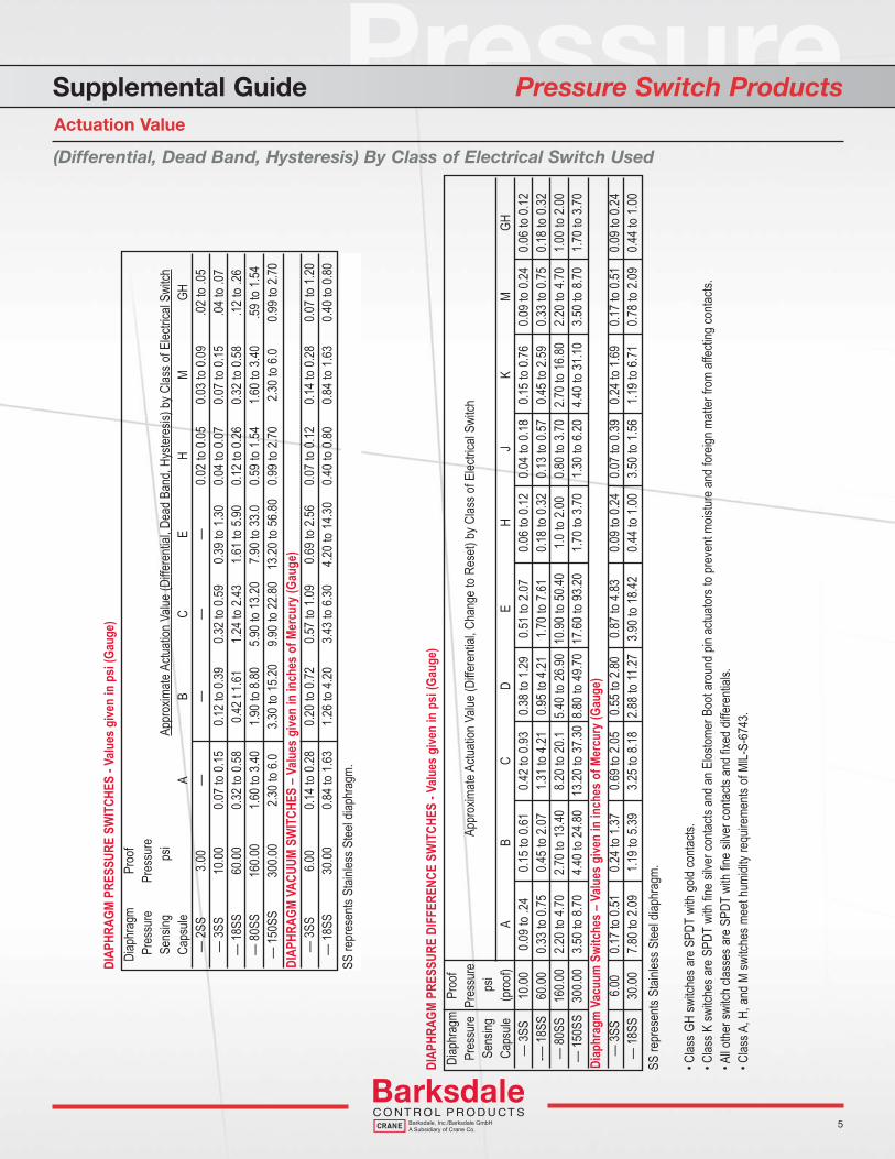
Supplemental Guide Pressure Switch ProductsActuation Value
(Differential, Dead Band, Hysteresis) By Class of Electrical Switch Used
DIAP
HRAG
M PR
ESSU
RE S
WIT
CHES
- Valu
es g
iven
in p
si (G
auge
)Di
aphr
agm
Proo
f Pr
essu
rePr
essu
reSe
nsing
psi
Appr
oxim
ate A
ctuati
on V
alue
(Dif fe
renti
al, D
ead
Band
, Hys
teres
is) b
y Clas
s of E
lectric
al Sw
itch
Caps
uleA
BC
EH
MGH
— 2
SS3.0
0—
——
—0.0
2 to
0.05
0.03
to 0.0
9.02
to .0
5—
3SS
10.00
0.07
to 0.1
50.1
2 to
0.39
0.32
to 0.5
90.3
9 to
1.30
0.04
to 0.0
70.0
7 to
0.15
.04 to
.07
— 1
8SS
60.00
0.32
to 0.5
80.4
2 t 1
.611.2
4 to
2.43
1.61
to 5.9
00.1
2 to
0.26
0.32
to 0.5
8.12
to .2
6—
80S
S16
0.00
1.60
to 3.4
01.9
0 to
8.80
5.90
to 13
.207.9
0 to
33.0
0.59
to 1.5
41.6
0 to
3.40
.59 to
1.54
— 1
50SS
300.0
02.3
0 to
6.03.3
0 to
15.20
9.90
to 22
.8013
.20 to
56.8
00.9
9 to
2.70
2.30
to 6.0
0.99
to 2.7
0DI
APHR
AGM
VACU
UM S
WIT
CHES
– Valu
es g
iven
in in
ches
of M
ercu
ry (G
auge
)—
3SS
6.00
0.14
to 0.2
80.2
0 to
0.72
0.57
to 1.0
90.6
9 to
2.56
0.07
to 0.1
20.1
4 to
0.28
0.07
to 1.2
0—
18S
S30
.000.8
4 to
1.63
1.26
to 4.2
03.4
3 to
6.30
4.20
to 14
.300.4
0 to
0.80
0.84
to 1.6
30.4
0 to
0.80
SS re
pres
ents
Stain
less S
teel d
iaphr
agm.
Diap
hrag
mPr
oof
Pres
sure
Pres
sure
Appr
oxim
ate A
ctuati
on V
alue
(Diffe
renti
al, C
hang
e to
Rese
t) by
Clas
s of E
lectric
al Sw
itch
Sens
ing
p
siCa
psule
(
proo
f)A
BC
DE
HJ
KM
GH—
3SS
10.00
0.09
to .24
0.15
to 0.6
10.4
2 to
0.93
0.38
to 1.2
90.5
1 to
2.07
0.06
to 0.1
20.0
4 to
0.18
0.15
to 0.7
60.0
9 to
0.24
0.06
to 0.1
2-—
18SS
60.00
0.33
to 0.7
50.4
5 to
2.07
1.31
to 4.2
10.9
5 to
4.21
1.70
to 7.6
10.1
8 to
0.32
0.13
to 0.5
70.4
5 to
2.59
0.33
to 0.7
50.1
8 to
0.32
—80
SS16
0.00
2.20
to 4.7
02.7
0 to
13.40
8.20
to 20
.15.4
0 to
26.90
10.90
to 5
0.40
1.0 to
2.00
0.80
to 3.7
02.7
0 to
16.80
2.20
to 4.7
01.0
0 to
2.00
—15
0SS
300.0
03.5
0 to
8.70
4.40
to 24
.8013
.20 to
37.3
08.8
0 to
49.70
17.60
to 9
3.20
1.70
to 3.7
01.3
0 to
6.20
4.40
to 31
.103.5
0 to
8.70
1.70
to 3.7
0Di
aphr
agm
Vac
uum
Swi
tche
s – V
alues
give
n in
inch
es o
f Mer
cury
(Gau
ge)
—3S
S6.0
00.1
7 to
0.51
0.24
to 1.3
70.6
9 to
2.05
0.55
to 2.8
00.8
7 to
4.83
0.09
to 0.2
40.0
7 to
0.39
0.24
to 1.6
90.1
7 to
0.51
0.09
to 0.2
4—
18SS
30.00
7.80
to 2.0
91.1
9 to
5.39
3.25
to 8.1
82.8
8 to
11.27
3.90
to 18
.420.4
4 to
1.00
3.50
to 1.5
61.1
9 to
6.71
0.78
to 2.0
90.4
4 to
1.00
DIAP
HRAG
M PR
ESSU
RE D
IFFE
RENC
E SW
ITCH
ES- V
alues
give
n in
psi
(Gau
ge)
SS re
pres
ents
Stain
less S
teel d
iaphr
agm.
• Clas
s GH
switc
hes a
re S
PDT
with
gold
conta
cts.
• Clas
s K sw
itche
s are
SPD
Twi
th fin
e sil
ver c
ontac
ts an
d an
Elos
tomer
Boo
t aro
und
pin a
ctuato
rs to
prev
ent m
oistur
e an
d for
eign
matte
r fro
m aff
ectin
g co
ntacts
.• A
ll othe
r swi
tch cl
asse
s are
SPD
Twi
th fin
e sil
ver c
ontac
ts an
d fix
ed d
iffere
ntials
.• C
lass A
, H, a
nd M
switc
hes m
eet h
umidi
ty re
quire
ments
of M
lL-S-
6743
.
See Barksdale’s Standard Conditions of Sale • Specifications are subject to modification at any time • Bulletin #S0092-A • 09/07 • ©2007 • Printed in the U.S.A.6
3211 Fruitland Avenue • Los Angeles, CA 90058 • 800-835-1060 • Fax: 323-589-3463 • www.barksdale.com
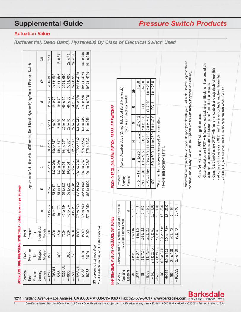
Supplemental Guide Pressure Switch ProductsActuation Value
BOUR
DON
TUBE
PRE
SSUR
E SW
ITCH
ES- V
alues
give
n in
psi
(Gau
ge)
Bour
don
Proo
fPr
oof
Appr
oxim
ate A
ctuati
on V
alue
(Diffe
renti
al, D
ead
Band
, Hys
teres
is) b
y Clas
s of E
lectric
al Sw
itch
Tube
Pres
sure
Pres
sure
Pres
sure
forfor
Sens
ingSt
rippe
dHo
useh
oldEl
emen
tMo
dels
Mode
lsA
BC
EH
MS*
*GH
— 1
2SS
1500
1800
11 to
27•
20 to
65
51 to
100
58 to
202
7 to
1411
to 2
795
to 1
907
to 14
—
20S
OUL
4800
19 to
79
51 to
171
132
to 26
015
4 to
547
16 to
39
19 to
79
243
to 50
8—
32S
S 40
0048
00
19 to
79
51 to
171
132
to 26
015
4 to
547
16 to
39
19 to
79
243
to 50
816
to 3
9—
32S
S-UL
7200
40 to
85•
59 to
226
163
to 34
120
4 to
787
22 to
40
40 to
85
300
to 69
5 —
48S
S 60
0072
0040
to 8
5•59
to 2
2616
3 to
341
204
to 78
722
to 4
040
to 8
530
0 to
695
22 to
40
— 6
5SS
8125
9750
54 to
115
76 to
301
215
to 45
427
2 to
1064
29 to
52
54 to
115
396
to 93
029
to 5
2—
72S
S-UL
1800
027
5 to
550•
366
to 15
2010
61 to
228
913
75 to
553
214
4 to
246
275
to 55
019
50 to
475
0—
120
SS15
000
1800
027
5 to
550•
366
to 15
2010
61 to
228
913
75 to
553
214
4 to
246
275
to 55
019
50 to
475
014
4 to
246
— 1
80SS
2000
024
000
275
to 55
0•36
6 to
1520
1061
to 2
289
1375
to 5
532
144
to 24
627
5 to
550
1950
to 4
750
144
to 24
6
Pres
sure
Appro
x. Ac
tuatio
n Valu
e (Di
fferen
tial, D
ead B
and,
Hyste
resis)
Sens
ingby
Clas
s of E
lectric
al Sw
itch
Elem
ent
BH/
GHM
– 30
.4 to
2.0•
.1 to
1.0x
1.0 -
1.5–
30SS
.4 to
2.0•
.1 to
1.01.0
- 1.5
– 85
.8 to
7.0•
.25 to
2.5
1.0 -
5.0–
85SS
.8 to
7.0•
.25 to
2.5
1.0 -
5.0–
340
2.0 to
22.0
•1.0
to 6
.02.0
- 10
.0–
340S
S2.0
to 2
2.0•
1.0 to
6.0
2.0 -
10.0
– 60
06.0
to 3
0.02.0
to 1
7.0•
3.6 -
23.0
– 60
0SS
6.0 to
30.0
2.0 to
17.0
•3.6
- 23
.0–
1600
25 to
100
20 to
70
20 -
95–
1600
SS25
to 1
0020
to 7
020
- 95
HI-P
(DIA
-SEA
LPI
STON
) PRE
SSUR
E SW
ITCH
ES
SS re
pres
ents
Stain
less S
teel.
**Not
avail
able
on d
ual o
r ULl
isted
switc
hes.
ECON
-O-T
ROL
(DIA
-SEA
LPI
STON
) PRE
SSUR
E SW
ITCH
ESPr
essu
re **
*Se
nsing
Appr
ox. A
ctuati
on V
alue
(Diffe
renti
al, D
ead
Band
, Hys
teres
is)
Elem
ent
by C
lass o
f Elec
trical
Switc
h
B
H
M
R
G
H–
15–
15†
.2 to
2.3
.1 to
.8•.2
to 1.2
.1
to .8
– 90
– 90
†1.0
to 1
0.5.5
to 8.0
•1.0
to 1
0.0
SEE
.5 to
8.0–
250–
250
†2.0
to 2
7.01.0
to
20.0•
2.0 to
21.0
CHAR
TS1.0
to 2
0.0–
500
6.0 to
50.0
4.0 t
o 28
.0•6.0
to 4
0.0PG
. 84.0
to 2
8.0***
Plain
num
bers
repr
esen
t untr
eated
alum
inum
fitting
.†
Repr
esen
ts po
lysulf
one
fitting
.
• ‘St
anda
rd’fo
r Reg
ular H
ouse
d an
d St
rippe
d (ch
eck w
ith yo
ur B
arks
dale
Contr
ols re
pres
entat
ivefor
pric
es a
nd d
elive
ry). A
ll othe
rs ar
e ‘S
pecia
l’(ch
eck w
ith fa
ctory
for p
rices
and
deli
very)
.
- Clas
s GH
switc
hes a
re S
PDT
with
gold
conta
cts.
- Clas
s K sw
itche
s are
SPD
Twi
th fin
e sil
ver c
ontac
ts an
d an
Elas
tomer
Boo
t aro
und
pinac
tuator
s to
prev
ent m
oistur
e an
d for
eign
matte
r fro
m aff
ectin
g co
ntacts
.- C
lass R
& S
switc
hes a
re S
PDT
with
fine
silve
r con
tacts
and
adjus
table
differ
entia
ls.- A
ll othe
r swi
tch cl
asse
s are
SPD
Twi
th fin
e sil
ver c
ontac
ts an
d fix
ed d
iffere
ntials
. - C
lass A
, H, &
M sw
itche
s mee
t hum
idity
requ
ireme
nts o
f MIL-
S-67
43.
(Differential, Dead Band, Hysteresis) By Class of Electrical Switch Used

Pressure
7
Supplemental Guide Pressure Switch ProductsElectrical Ratings
(Current Given in Ampere)
CLASS OF INRUSH MOTOR LAMP INDUC- RESIS-SWITCH VOLTS N.C. N.O. N.C. N.O. N.C. N.O. TIVE* TIVE
125 30.0 15.0 3.0 1.5 10.0 10.0A,H 250 30.0 15.0 3.0 1.5 10.0 10.0
480 15.0 7.5 3.0 1.5 3.0 3.0600125 30.0 15.0 3.0 1.5 10.0 10.0
B,K 250 30.0 15.0 3.0 1.5 10.0 10.0480 30.0 15.0 3.0 1.5 10.0 10.0
0.20.20.510.03006125 30.0 15.0 3.0 1.5 10.0 10.0
C 250 30.0 15.0 3.0 1.5 10.0 10.0480 30.0 15.0 3.0 1.5 10.0 10.0
0.20.20.510.03006125 75.0 75.0 12.5 12.5 7.5 7.5 15.0 15.0
E 250 75.0 75.0 12.5 12.5 7.5 7.5 15.0 15.0480 75.0 75.0 12.5 12.5 7.5 7.5 15.0 15.0
0.20.20.570.57006125 44.0 22.0 5.8 5.8 3.0 1.5 15.0 15.0
L 250 44.0 22.0 4.9 4.9 3.0 1.5 15.0 15.0480 44.0 22.0 3.0 1.5 15.0 15.0600125 30.0 15.0 3.0 1.5 10.0 10.0
M 250 30.0 15.0 3.0 1.5 10.0 10.0480 15.0 7.5 3.0 1.5 3.0 3.0600125 75.0 75.0 12.5 12.5 7.5 7.5 15.0 15.0
R,S 250 75.0 75.0 12.5 12.5 7.5 7.5 15.0 15.0480 75.0 75.0 12.5 12.5 7.5 7.5 15.0 15.0600125 2.0 1.0 .7 .35 .2 .1 1.0 1.0
GH 250480600
AA 125 4.0 4.0250HH 125 5.0 5.0250BB 125 5.0 5.0250CC 125 10.0 10.0250
CLASS OF INRUSH MOTOR LAMP INDUC- RESIS-SWITCH VOLTS*** N.C. N.O. N.C. N.O. N.C. N.O. TIVE** TIVE
6 .5 .5 .5 .5 .5 .5A,H 12 .5 .5 .5 .5 .5 .5
24 .5 .5 .5 .5 .5 .56 30.0 15.0 3.0 1.5 15.0 15.012 30.0 15.0 3.0 1.5 10.0 15.0
B,K 24 30.0 15.0 3.0 1.5 5.0 6.0125 4.0 4.0 .4 .4 .05 .4250 2.0 2.0 .2 .2 .03 .2
6 30.0 15.0 3.0 1.5 15.0 15.012 30.0 15.0 3.0 1.5 15.0 15.0
C 24 30.0 15.0 3.0 1.5 10.0 10.0125 6.0 6.0 .6 .6 .1 .6250 3.0 3.0 .3 .3 .05 .3
6 30.0 15.0 5.0 2.5 3.0 1.5 15.0 15.012 30.0 15.0 5.0 2.5 3.0 1.5 15.0 15.0
E,R,S 24 30.0 15.0 5.0 2.5 3.0 1.5 5.0 6.0125 4.0 4.0 .8 .8 .4 .4 .05 .4250 2.0 2.0 .4 .4 .2 .2 .03 .2
6 44.0 22.0 5.0 2.5 3.0 1.5 8.0 22.012 44.0 22.0 5.0 2.5 3.0 1.5 5.0 22.0
L 24 44.0 22.0 5.0 2.5 3.0 1.5 1.0 2.0125 4.0 4.0 .8 .8 .4 .4 .03 .4250 2.0 2.0 .4 .4 .2 .2 .02 .2
6 30.0 15.0 3.0 1.5 8.0 15.012 30.0 15.0 3.0 1.5 5.0 15.0
M 24 30.0 15.0 3.0 1.5 1.0 2.0125 4.0 4.0 .4 .4 .5 .75250 2.0 2.0 .2 .2 .25 .4
6 2.0 1.0 .7 .35 .2 .1 1.0 1.0GH 12 2.0 1.0 .7 .35 .2 .1 1.0 1.0
24 2.0 1.0 .7 .35 .2 .1 1.0 1.0
**L/R = .026. L/R is the ratio of inductance to resistance. It is the timerequired for the current to rise to 63% of the maximum value.
***6, 12 and 24 VDC electrical ratings are for engineering reference only.These ratings are not recognized by the UL and CSA. Standardnameplate marking does not include these ratings.
*50% Power Factor
- Class GH switches are SPDT with gold contacts.- Class R & S switches are SPDT with fine silver contacts and adjustable
differentials.- All other switch classes are SPDT with fine silver contacts and fixed
differentials. - Class A, H & M switches meet humidity requirements of MIL-S-6743.
A.C. RATINGS (60 Cycles)All altitudes to 45,000 feet30° C Maximum temperature rise.
D.C. RATINGSAll altitudes to 45,000 feet
See Barksdale’s Standard Conditions of Sale • Specifications are subject to modification at any time • Bulletin #S0092-A • 09/07 • ©2007 • Printed in the U.S.A.8
3211 Fruitland Avenue • Los Angeles, CA 90058 • 800-835-1060 • Fax: 323-589-3463 • www.barksdale.com
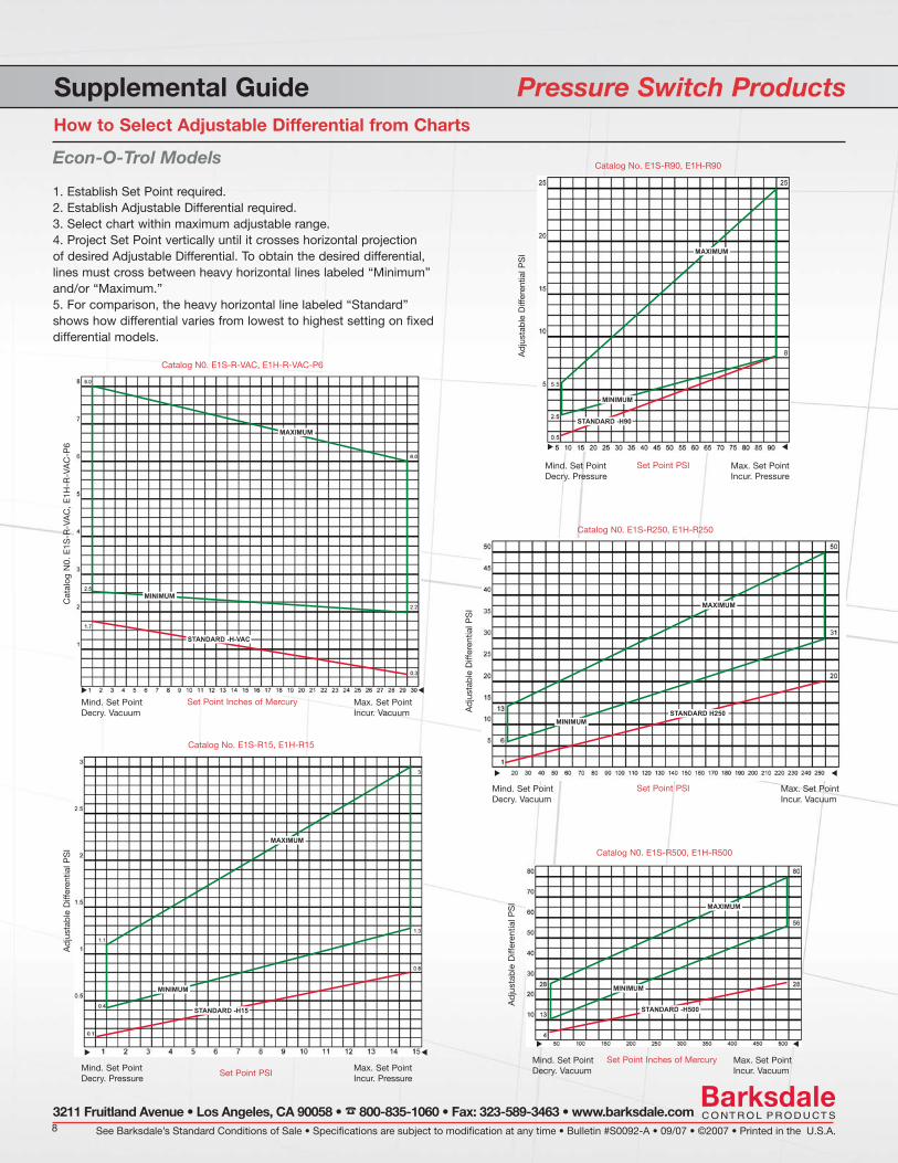
Supplemental Guide Pressure Switch ProductsHow to Select Adjustable Differential from Charts
Econ-O-Trol Models
1. Establish Set Point required.2. Establish Adjustable Differential required.3. Select chart within maximum adjustable range.4. Project Set Point vertically until it crosses horizontal projection of desired Adjustable Differential. To obtain the desired differential, lines must cross between heavy horizontal lines labeled “Minimum” and/or “Maximum.”5. For comparison, the heavy horizontal line labeled “Standard” shows how differential varies from lowest to highest setting on fixed differential models.
Catalog N0. E1S-R-VAC, E1H-R-VAC-P6
Cat
alog
N0.
E1S
-R-V
AC
, E
1H-R
-VA
C-P
6
Set Point Inches of MercurySTANDARD H250
MAXIMUM
MINIMUM
Max. Set Point Incur. Vacuum
Mind. Set Point Decry. Vacuum
Catalog No. E1S-R15, E1H-R15
Ad
just
able
Diff
eren
tial P
SI
Set Point PSIMax. Set Point Incur. Pressure
Mind. Set Point Decry. Pressure
Catalog No. E1S-R90, E1H-R90
Ad
just
able
Diff
eren
tial P
SI
Set Point PSI Max. Set Point Incur. Pressure
Mind. Set Point Decry. Pressure
Catalog N0. E1S-R250, E1H-R250
Ad
just
able
Diff
eren
tial P
SI
Set Point PSI Max. Set Point Incur. Vacuum
Mind. Set Point Decry. Vacuum
Catalog N0. E1S-R500, E1H-R500
Ad
just
able
Diff
eren
tial P
SI
Set Point Inches of Mercury Max. Set Point Incur. Vacuum
Mind. Set Point Decry. Vacuum
Pressure
9
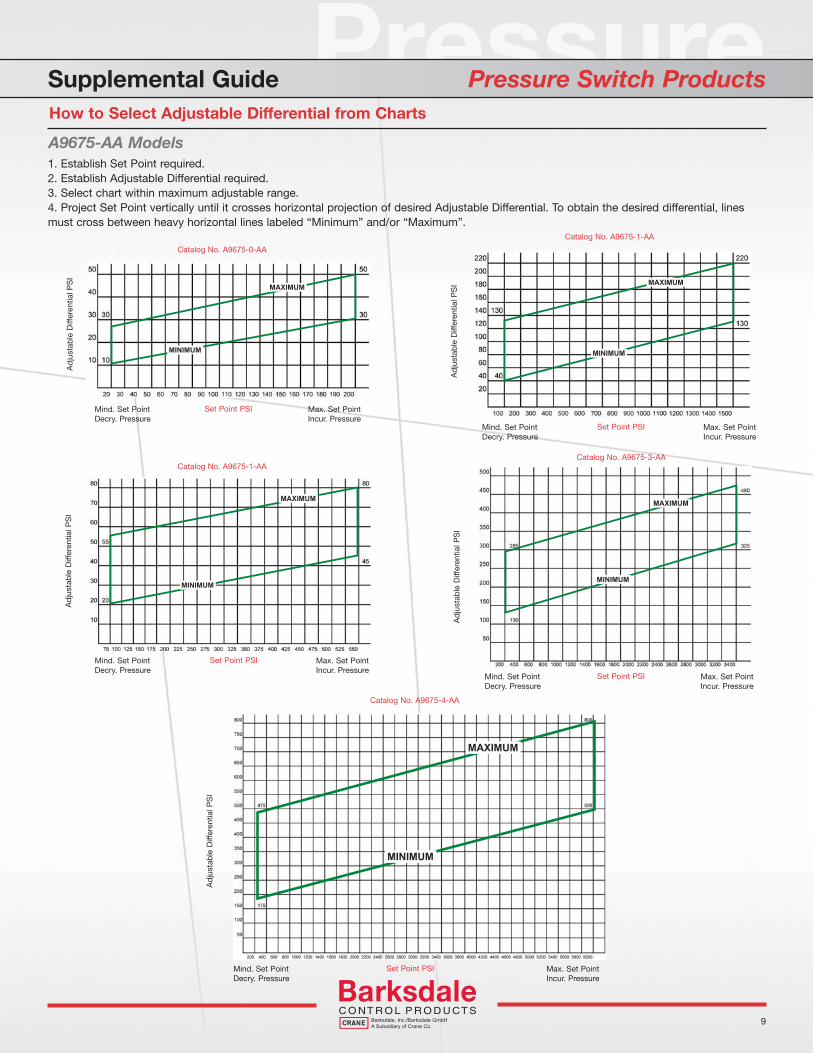
Supplemental Guide Pressure Switch ProductsHow to Select Adjustable Differential from Charts
A9675-AA Models1. Establish Set Point required.2. Establish Adjustable Differential required.3. Select chart within maximum adjustable range.4. Project Set Point vertically until it crosses horizontal projection of desired Adjustable Differential. To obtain the desired differential, lines must cross between heavy horizontal lines labeled “Minimum” and/or “Maximum”.
Catalog No. A9675-0-AA
Ad
just
able
Diff
eren
tial P
SI
Set Point PSI Max. Set Point Incur. Pressure
Mind. Set Point Decry. Pressure
Catalog No. A9675-1-AA
Ad
just
able
Diff
eren
tial P
SI
Set Point PSI Max. Set Point Incur. Pressure
Mind. Set Point Decry. Pressure
Catalog No. A9675-1-AA
Ad
just
able
Diff
eren
tial P
SI
Set Point PSI Max. Set Point Incur. Pressure
Mind. Set Point Decry. Pressure
Catalog No. A9675-3-AAA
dju
stab
le D
iffer
entia
l PS
I
Set Point PSI Max. Set Point Incur. Pressure
Mind. Set Point Decry. Pressure
Catalog No. A9675-4-AA
Ad
just
able
Diff
eren
tial P
SI
Set Point PSI Max. Set Point Incur. Pressure
Mind. Set Point Decry. Pressure
See Barksdale’s Standard Conditions of Sale • Specifications are subject to modification at any time • Bulletin #S0092-A • 09/07 • ©2007 • Printed in the U.S.A.10
3211 Fruitland Avenue • Los Angeles, CA 90058 • 800-835-1060 • Fax: 323-589-3463 • www.barksdale.com
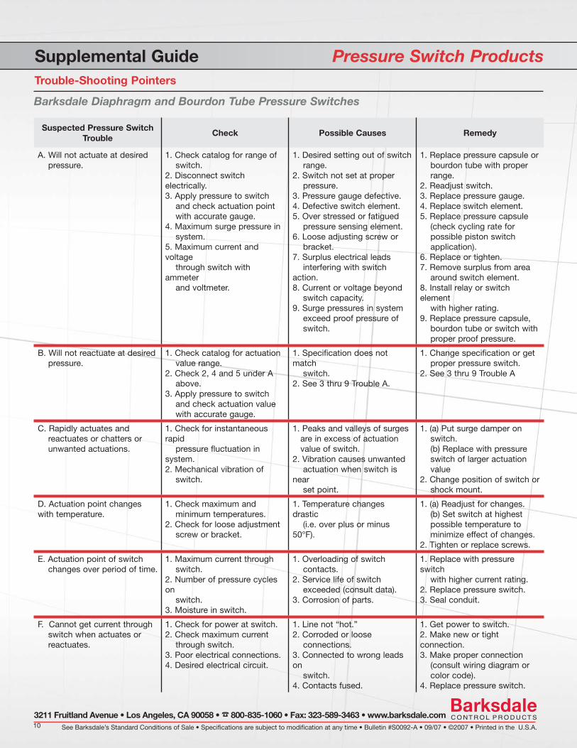
Supplemental Guide Pressure Switch ProductsTrouble-Shooting Pointers
Barksdale Diaphragm and Bourdon Tube Pressure Switches
Suspected Pressure Switch Trouble
Check Possible Causes Remedy
A. Will not actuate at desired pressure.
1. Check catalog for range of switch.2. Disconnect switch electrically. 3. Apply pressure to switch and check actuation point with accurate gauge.4. Maximum surge pressure in system.5. Maximum current and voltage through switch with ammeter and voltmeter.
1. Desired setting out of switch range.2. Switch not set at proper pressure.3. Pressure gauge defective. 4. Defective switch element.5. Over stressed or fatigued pressure sensing element.6. Loose adjusting screw or bracket.7. Surplus electrical leads interfering with switch action.8. Current or voltage beyond switch capacity.9. Surge pressures in system exceed proof pressure of switch.
1. Replace pressure capsule or bourdon tube with proper range.2. Readjust switch.3. Replace pressure gauge. 4. Replace switch element.5. Replace pressure capsule (check cycling rate for possible piston switch application).6. Replace or tighten.7. Remove surplus from area around switch element.8. Install relay or switch element with higher rating.9. Replace pressure capsule, bourdon tube or switch with proper proof pressure.
B. Will not reactuate at desired pressure.
1. Check catalog for actuation value range.2. Check 2, 4 and 5 under A above.3. Apply pressure to switch and check actuation value with accurate gauge.
1. Specifi cation does not match switch.2. See 3 thru 9 Trouble A.
1. Change specifi cation or get proper pressure switch.2. See 3 thru 9 Trouble A
C. Rapidly actuates and reactuates or chatters or unwanted actuations.
1. Check for instantaneous rapid pressure fl uctuation in system. 2. Mechanical vibration of switch.
1. Peaks and valleys of surges are in excess of actuation value of switch.2. Vibration causes unwanted actuation when switch is near set point.
1. (a) Put surge damper on switch. (b) Replace with pressure switch of larger actuation value 2. Change position of switch or shock mount.
D. Actuation point changes with temperature.
1. Check maximum and minimum temperatures.2. Check for loose adjustment screw or bracket.
1. Temperature changes drastic (i.e. over plus or minus 50°F).
1. (a) Readjust for changes. (b) Set switch at highest possible temperature to minimize effect of changes.2. Tighten or replace screws.
E. Actuation point of switch changes over period of time.
1. Maximum current through switch.2. Number of pressure cycles on switch.3. Moisture in switch.
1. Overloading of switch contacts.2. Service life of switch exceeded (consult data).3. Corrosion of parts.
1. Replace with pressure switch with higher current rating.2. Replace pressure switch. 3. Seal conduit.
F. Cannot get current through switch when actuates or reactuates.
1. Check for power at switch.2. Check maximum current through switch.3. Poor electrical connections. 4. Desired electrical circuit.
1. Line not “hot.”2. Corroded or loose connections.3. Connected to wrong leads on switch.4. Contacts fused.
1. Get power to switch.2. Make new or tight connection.3. Make proper connection (consult wiring diagram or color code).4. Replace pressure switch.
Pressure
11
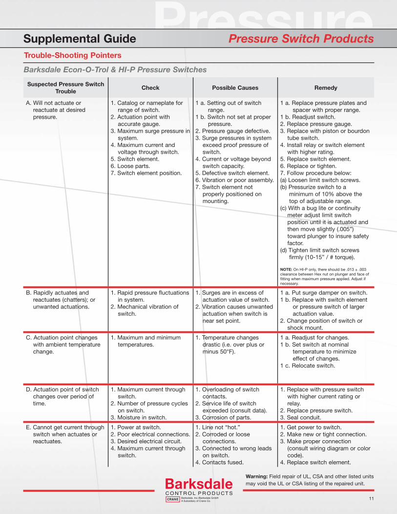
Supplemental Guide Pressure Switch ProductsTrouble-Shooting Pointers
Barksdale Econ-O-Trol & HI-P Pressure Switches
Suspected Pressure Switch Trouble
Check Possible Causes Remedy
A. Will not actuate or reactuate at desired pressure.
1. Catalog or nameplate for range of switch.2. Actuation point with accurate gauge.3. Maximum surge pressure in system.4. Maximum current and voltage through switch.5. Switch element. 6. Loose parts.7. Switch element position.
1 a. Setting out of switch range. 1 b. Switch not set at proper pressure.2. Pressure gauge defective.3. Surge pressures in system exceed proof pressure of switch. 4. Current or voltage beyond switch capacity.5. Defective switch element. 6. Vibration or poor assembly. 7. Switch element not properly positioned on mounting.
1 a. Replace pressure plates and spacer with proper range.1 b. Readjust switch.2. Replace pressure gauge.3. Replace with piston or bourdon tube switch.4. Install relay or switch element with higher rating.5. Replace switch element. 6. Replace or tighten.7. Follow procedure below:(a) Loosen limit switch screws.(b) Pressurize switch to a minimum of 10% above the top of adjustable range.(c) With a bug lite or continuity meter adjust limit switch position until it is actuated and then move slightly (.005”) toward plunger to insure safety factor.(d) Tighten limit switch screws fi rmly (10-15” / # torque).
NOTE: On HI-P only, there should be .013 ± .003 clearance between Hex nut on plunger and face of fi tting when maximum pressure applied. Adjust if necessary.
B. Rapidly actuates and reactuates (chatters); or unwanted actuations.
1. Rapid pressure fl uctuations in system.2. Mechanical vibration of switch.
1. Surges are in excess of actuation value of switch.2. Vibration causes unwanted actuation when switch is near set point.
1 a. Put surge damper on switch.1 b. Replace with switch element or pressure switch of larger actuation value.2. Change position of switch or shock mount.
C. Actuation point changes with ambient temperature change.
1. Maximum and minimum temperatures.
1. Temperature changes drastic (i.e. over plus or minus 50°F).
1 a. Readjust for changes.1 b. Set switch at nominal temperature to minimize effect of changes.1 c. Relocate switch.
D. Actuation point of switch changes over period of time.
1. Maximum current through switch.2. Number of pressure cycles on switch.3. Moisture in switch.
1. Overloading of switch contacts.2. Service life of switch exceeded (consult data).3. Corrosion of parts.
1. Replace with pressure switch with higher current rating or relay.2. Replace pressure switch. 3. Seal conduit.
E. Cannot get current through switch when actuates or reactuates.
1. Power at switch.2. Poor electrical connections. 3. Desired electrical circuit.4. Maximum current through switch.
1. Line not “hot.”2. Corroded or loose connections.3. Connected to wrong leads on switch.4. Contacts fused.
1. Get power to switch.2. Make new or tight connection.3. Make proper connection (consult wiring diagram or color code).4. Replace switch element.
Warning: Field repair of UL, CSA and other listed units may void the UL or CSA listing of the repaired unit.
See Barksdale’s Standard Conditions of Sale • Specifications are subject to modification at any time • Bulletin #S0092-A • 09/07 • ©2007 • Printed in the U.S.A.12
3211 Fruitland Avenue • Los Angeles, CA 90058 • 800-835-1060 • Fax: 323-589-3463 • www.barksdale.com
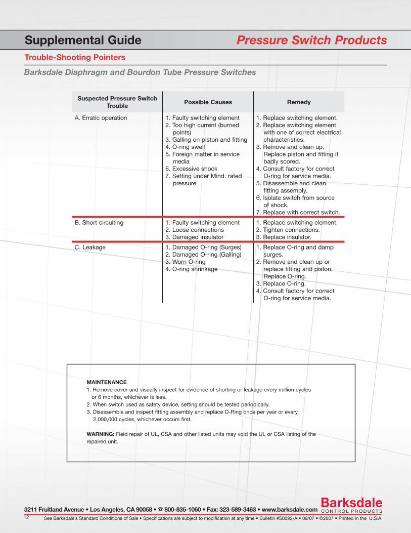
Supplemental Guide Pressure Switch ProductsTrouble-Shooting Pointers
Barksdale Diaphragm and Bourdon Tube Pressure Switches
Suspected Pressure Switch Trouble
Possible Causes Remedy
A. Erratic operation 1. Faulty switching element2. Too high current (burned points)3. Galling on piston and fi tting4. O-ring swell5. Foreign matter in service media 6. Excessive shock7. Setting under Mind. rated pressure
1. Replace switching element.2. Replace switching element with one of correct electrical characteristics.3. Remove and clean up. Replace piston and fi tting if badly scored.4. Consult factory for correct O-ring for service media.5. Disassemble and clean fi tting assembly. 6. Isolate switch from source of shock.7. Replace with correct switch.
B. Short circuiting 1. Faulty switching element 2. Loose connections3. Damaged insulator
1. Replace switching element. 2. Tighten connections.3. Replace insulator.
C. Leakage 1. Damaged O-ring (Surges) 2. Damaged O-ring (Galling) 3. Worn O-ring4. O-ring shrinkage
1. Replace O-ring and damp surges.2. Remove and clean up or replace fi tting and piston. Replace O-ring.3. Replace O-ring.4. Consult factory for correct O-ring for service media.
MAINTENANCE1. Remove cover and visually inspect for evidence of shorting or leakage every million cycles or 6 months, whichever is less.2. When switch used as safety device, setting should be tested periodically.3. Disassemble and inspect fi tting assembly and replace O-Ring once per year or every 2,000,000 cycles, whichever occurs fi rst.
WARNING: Field repair of UL, CSA and other listed units may void the UL or CSA listing of the repaired unit.