pressure relief valve, - cma/flodyne/hydradyne pdfs/brh std valves/pressure/rexro… · 4/12 bosch...
TRANSCRIPT
Electric Drivesand Controls Hydraulics
Linear Motion andAssembly Technologies Pneumatics Service
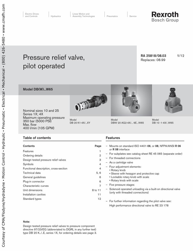
Nominal sizes 10 and 25Series 1X; 4XMaximum operating pressure 350 bar (5000 PSI)Max. flow 400 l/min (105 GPM)
1/12RA 25818/08.03
Replaces: 08.99Pressure relief valve,
pilot operated
Model DB(W)...W65
Table of contents
Contents Page
Features 1
Ordering details 2
Design tested pressure relief valves 3
Symbols 4
Functional description, cross-section 4
Technical data 5, 6
General guidelines 6
Plug-in connector 6
Characteristic curves 7
Unit dimensions 8 to 11
Installation cavities 11
Standard types 12
Features
– Mounts on standard ISO 4401-06, or 08, NFPA/ANSI R 06
or R 08 interface
– For subplates see catalog sheet RE 45 065 (se pa ra te order)
– For threaded connections
– As a cartridge valve
– Four adjustment elements:
• Rotary knob
• Sleeve with hexagon and protective cap
• Lockable rotary knob with scale
• Rotary knob with scale
– Five pressure stages
– Solenoid operated unloading via a built-on directional valve
(only with threaded connections)
– For further information regarding the pilot valve see:
High performance directional valve to RE 23 178
Model
DB 10 -1-4X/..W65
Model
DBW 20 AG2-4X/... 6E...W65
Model
DB 20 K1-4X/...XY
Note:
Design tested pressure relief valves to pressure component
directive 97/23/EG (abbreviated to DGRL in any further text)
type DB 20 K../..E, series 1X, for ordering details see page 3.
Cou
rtes
y of
CM
A/F
lody
ne/H
ydra
dyne
▪ M
otio
n Con
trol
▪ H
ydra
ulic
▪ P
neum
atic
▪ E
lect
rica
l ▪ M
echa
nica
l ▪ (
800)
426
-548
0 ▪
ww
w.c
maf
h.co
m

2/12 Bosch Rexroth Corp. | Industrial Hydraulics DB(W)...W65 | RE 25818/08.03
No BSP
Code = Thread
Port
12 = SAE threaded ext. connections
Design tested:
No code= Without
E = Safety valve with design testing
to DGRL 97/23/EG
W65 = Vertical cartridge (ordering details are not required for
cartridge valve “K”)
No code = NBR seals
V = FKM seals
(other seals on request)
Attention!
The compatibility of the seals and pressure fl uid has to be taken into account!
Electrical connection 2)
K4 6) = Without plug-in connector Individual connection with component plug DIN EN 175 301-803
No code 2) = Without hand override
N 2) = With hand override
N9 2) = With protected hand override
G24 2) = 24 V DC
W230 2) = 230 V AC 50/60 Hz
No code = Without directional valve
6E 2) = With directional valve NS 6
No code = Lowest circulation pressure
U 4) = See characteristic curves on page 7
Pressure relief valve = DB
Without directional valve = No code
With built-on directional valve = W 1)
Normally closed = A 2)
Normally open = B 2)
For subplate mounting = –
For threaded connections = G
As a cartridge valve (cartridge) = K
Adjustment element
Rotary knob = 1
Sleeve with hexagon and protective cap = 2
Lockable rotary knob with scale = 3 3)
Rotary knob with scale = 7
Series 10 to 19 (only version “K”) = 1X
(10 to 19: unchanged installation and connection dimensions)
Series 40 to 49 = 4X
(40 to 49: unchanged installation and connection dimensions)
Settable pressure up to 50 bar (725 PSI) = 50
Settable pressure up to 100 bar (1450 PSI) = 100
Settable pressure up to 200 bar (2900 PSI) = 200
Settable pressure up to 315 bar (4600 PSI) = 315
Settable pressure up to 350 bar (5100 PSI) (only version DB) = 350
Pilot oil supply and pilot oil drain
Internal pilot oil supply and pilot oil drain = – 5)
External pilot oil supply, internal pilot oil drain Also see = X
Internal pilot oil supply, external pilot oil drain symbols = Y
External pilot oil supply and pilot oil drain on page 4 = XY
DB –
A B
P T
a b
A B
P T
a b
*
Ordering details
1) Only for valve with threaded connections
2) Only version DBW..G..
3) H-key to Material No. R900008158
is included within the scope of supply
4) Version “U” is not suitable for a
cross-relief function!
5) Hyphen „–“ only required for DBW..G ..
without stating details regarding X, Y, XY, and U.
NSOrdering details
Subplatemounting
“–“
Threadedconnection
“G“
Cartridgevalve“K“
10 = 10 = 10 (G 1/2)
25 = 15 (G 3/4)
= 20 = 20 (G 1) = 20
}
6) Plug-in connectors must be ordered separately
(see page 6).
Attention!
When ordering spare cartridges for subplate mounting or
threaded connection housings NS 10 and 25 always
order type DB 20 K.-1X/..XY!
Design tested safety valves are only available for
type DB 20 K.-1X/..YE!
Further detailsin clear text
Cou
rtes
y of
CM
A/F
lody
ne/H
ydra
dyne
▪ M
otio
n Con
trol
▪ H
ydra
ulic
▪ P
neum
atic
▪ E
lect
rica
l ▪ M
echa
nica
l ▪ (
800)
426
-548
0 ▪
ww
w.c
maf
h.co
m
RE 25818/08.03 | DB(W)...W65 Industrial Hydraulics | Bosch Rexroth Corp. 3/12
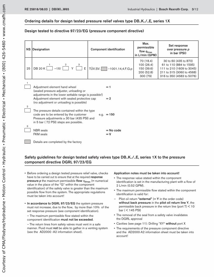
NS Designation Component identifi cation
Max.
permissible
fl ow qVmax
in L/min (GPM)
Set response
over pressure p
in bar (PSI)
25
1 2 3
DB 20 K –1X/ Y E TÜV.SV. –1001.14,4.F.G.p
70 (18.4)
100 (26.4)
150 (39.6)
200 (52.8)
300 (79)
30 to 60 (435 to 870)
61 to 110 (884 to 1595)
111 to 210 (1609 to 3045)
211 to 315 (3060 to 4568)
316 to 350 (4583 to 5076)
• Before ordering a design tested pressure relief valve, checks
have to be carried out to ensure that at the required response
pressure p the maximum permissible fl ow qVmax (= numerical
value in the place of the “G“ within the component
identifi cation) of the safety valve is greater than the maximum
possible fl ow from the system. The appropriate regulations
must be taken into account!
• In accordance to DGRL 97/23/EG the system pressure
must not increase, due to the fl ow, by more than 10% of the
set response pressure (see component identifi cation).
– The maximum permissible fl ow stated within the
component identifi cation must not be exceeded.
– The return lines from safety valves must vent in a safe
manner. Fluid must not be able to gather in a venting system
(see the AD2000 -A2 information sheet).
Application notes must be taken into account!
• The response value stated within the component
identifi cation is set in the manufacturing plant with a fl ow of
2 L/min (0.52 GPM).
• The maximum permissible fl ow stated within the component
identifi cation is valid for:
– Pilot oil return “external” (= Y in the order code)
without back pressure in the pilot oil return line Y, the
permissible back pressure in the return line (port T) < 10
bar ( < 145 PSI)
• The removal of the seal from a safety valve invalidates
the DGRL approval
• Cavities (see page 11): Drilling “XY“ without port X
• The requirements of the pressure component directive
and the AD2000-A2 information sheet must be taken into
account!
Ordering details for design tested pressure relief valves type DB..K../..E, series 1X
Design tested to directive 97/23/EG (pressure component directive)
Safety guidelines for design tested safety valves type DB..K../..E, series 1X to the pressure
component directive DGRL 97/23/EG
1
Adjustment element hand wheel = 1
(sealed pressure adjuster, unloading or
adjustments in the lower settable range is possible!)
Adjustment element with sealed protective cap = 2
(no adjustment or unloading is possible)
2
The pressure details contained within the type
code are to be entered by the customer e.g. = 150
Pressure adjustments ≥ 30 bar (435 PSI) and
in 5 bar ( 72 PSI) steps are possible.
3
NBR seals = No code
FKM seals = V
Details are completed by the factory
Cou
rtes
y of
CM
A/F
lody
ne/H
ydra
dyne
▪ M
otio
n Con
trol
▪ H
ydra
ulic
▪ P
neum
atic
▪ E
lect
rica
l ▪ M
echa
nica
l ▪ (
800)
426
-548
0 ▪
ww
w.c
maf
h.co
m

4/12 Bosch Rexroth Corp. | Industrial Hydraulics DB(W)...W65 | RE 25818/08.03
Y
X P T
9
5
12
3
13 4
10
11
1
6
8
7
2
P
T X
P
T Y
P
T YX
P
T
A B
P T
a b
A B
P T
a b
P
T
A B
P T
a b
A B
P T
a b
X
P
T
A B
P T
a b
A B
P T
a b
Y
P
T
A B
P T
a b
A B
P T
a b
X Y
P
T
Functional description, cross-section
Symbols
Types DB and DBW valves are pilot operated pressure relief
valves of cartridge design. They are used for limiting (DB)
or limiting and solenoid operated unloading (DBW only with
threaded connections) of an operating pressure.
The valves basically consists of the housing (1) and a pressure
control valve cartridge (2).
The pressure present in port P acts on the spool (3). At the
same time pressure is applied to poppet (6) via orifi ce drillings
(4 and 5). When the pressure port P exceeds the force set on
the spring (7), the poppet (6) opens against the spring (7).
Pressure fl uid can now fl ow from port P via the orifi ce drillings
(4 und 5) into the spring chamber (8). From here the fl uid is led
internally, with type DB..-4X/.. , via control passages (9 and 10)
or externally, with type DB..-4X/..Y.. , via control passages (9
and 11) to the tank.
Due to the balanced condition at the poppet (3) pressure fl uid
fl ows from port P to port T, while maintaining the set operating
pressure.
A pressure gauge connection (12) allows the operating
pressure to be monitored.
The pressure relief valve can be unloaded or switched over to
another pressure value (second pressure stage) via port “X”
(13).
Pressure relief valve type DBW (only threaded connections)
In principle, the function of this valve corresponds to that of the
valve type DB.
Unloading of the main poppet is achieved by controlling the
built-on directional valve.
Type DB 20-1-4X/...W65
Type DB…XY…Type DB…X… Type DB…–… Type DB…Y…
Type DBW…XY…Type DBW…X…Type DBW…–… Type DBW…Y…
Normally closed
Normally open
Normally closed
Normally open
Normally closed
Normally open
Normally closed
Normally open
Cou
rtes
y of
CM
A/F
lody
ne/H
ydra
dyne
▪ M
otio
n Con
trol
▪ H
ydra
ulic
▪ P
neum
atic
▪ E
lect
rica
l ▪ M
echa
nica
l ▪ (
800)
426
-548
0 ▪
ww
w.c
maf
h.co
m

RE 25818/08.03 | DB(W)...W65 Industrial Hydraulics | Bosch Rexroth Corp. 5/12
General
Installation Optional
Ambient temperature range Type DB.. °C (°F) –30 to +80 (–22 to 176) (NBR seals)
–15 to +80 (5 to 176)(FKM seals)
Type DBW..G.. °C (°F) –30 to +50 (–22 to 122) (NBR seals)
–15 to +50 (5 to 122) (FKM seals)
The minimum housing material strength Housing materials are to be so selected that adequate safety is
ensured for all conceivable operating pressures
(e.g. with reference to the compressive strength, thread
strength and tightening torques).
Weight NS 10 25
Subplate mounting kg (lbs) 1.6 (3.5) 2.3 (5.06)
Threaded connections Type DB.. kg (lbs) 2.95 (6.5) 2.95 (6.5)
Type DBW.. kg (lbs) 4.25 (9.4) 4.25 (9.3)
Cartridge valve (cartridge) kg (lbs) – 0.35 (0.8)
Directional valve technical data See catalogue sheet RE 23 178
Hydraulic (measured with HLP 46, ϑoil = 40 °C ± 5 °C)
Max. operating pressure, Ports P, X bar (PSI) 350 (5075)
Port T bar (PSI) 315 (4570)
Max. back pressure: Port Y Type DB.. bar (PSI) 250 (3635)
Port Y (DBW..G../..Y) or port T (DBW..G../..) bar (PSI) 210 (3000) for a DC solenoid
160 (2320) for an AC solenoid
Settable pressure Min. bar (PSI) Dependent on qv, see characteristic curves on page 5
Max. bar (PSI) Up to 50, Up to 100, Up to 200, Up to 315; (Up to 350 only version DB)
(725; 1150; 2900; 4570; (DB - 5075))
Maximum fl ow NS 10 25
Subplate mounting L/min (GPM) 200 (52.8) 400 (105.6)
Threaded connections L/min (GPM) 150 (39.6) 200 (52.8) (G 3/4);
300 (79) (G 1)
Pressure fl uid Mineral oil (HL, HLP) to DIN 51 524 1);
Fast bio-degradable pressure fl uids to
VDMA 24 568 (also see RE 90 221); HETG (rape seed oil) 1);
HEPG (polyglycole) 2); HEES (synthetic ester) 2);
other seals on request
Pressure fl uid temperature range °C (°F) –30 to +80 (–22 to 176) (NBR seals)
–15 to +80 (5 to 176) (FKM seals)
Viscosity range mm2/s (SUS) 10 to 800 (46 to 3708)
ISO code cleanliness class Maximum permissible degree of contamination of the pressure
fl uid is to ISO 4406 class 20/18/15 3)
1) Suitable for NBR and FKM seals
2) Only suitable for FKM seals
3) The cleanliness class stated for the components must be adhered to in hydraulic systems. Effective fi ltration prevents faults
from occurring and at the same time increases the component service life.
For the selection of fi lters see catalogue sheets RE 50 070, RE 50 076 and RE 50 081.
Technical data (for applications outside these parameters, please consult us!)
Cou
rtes
y of
CM
A/F
lody
ne/H
ydra
dyne
▪ M
otio
n Con
trol
▪ H
ydra
ulic
▪ P
neum
atic
▪ E
lect
rica
l ▪ M
echa
nica
l ▪ (
800)
426
-548
0 ▪
ww
w.c
maf
h.co
m
6/12 Bosch Rexroth Corp. | Industrial Hydraulics DB(W)...W65 | RE 25818/08.03
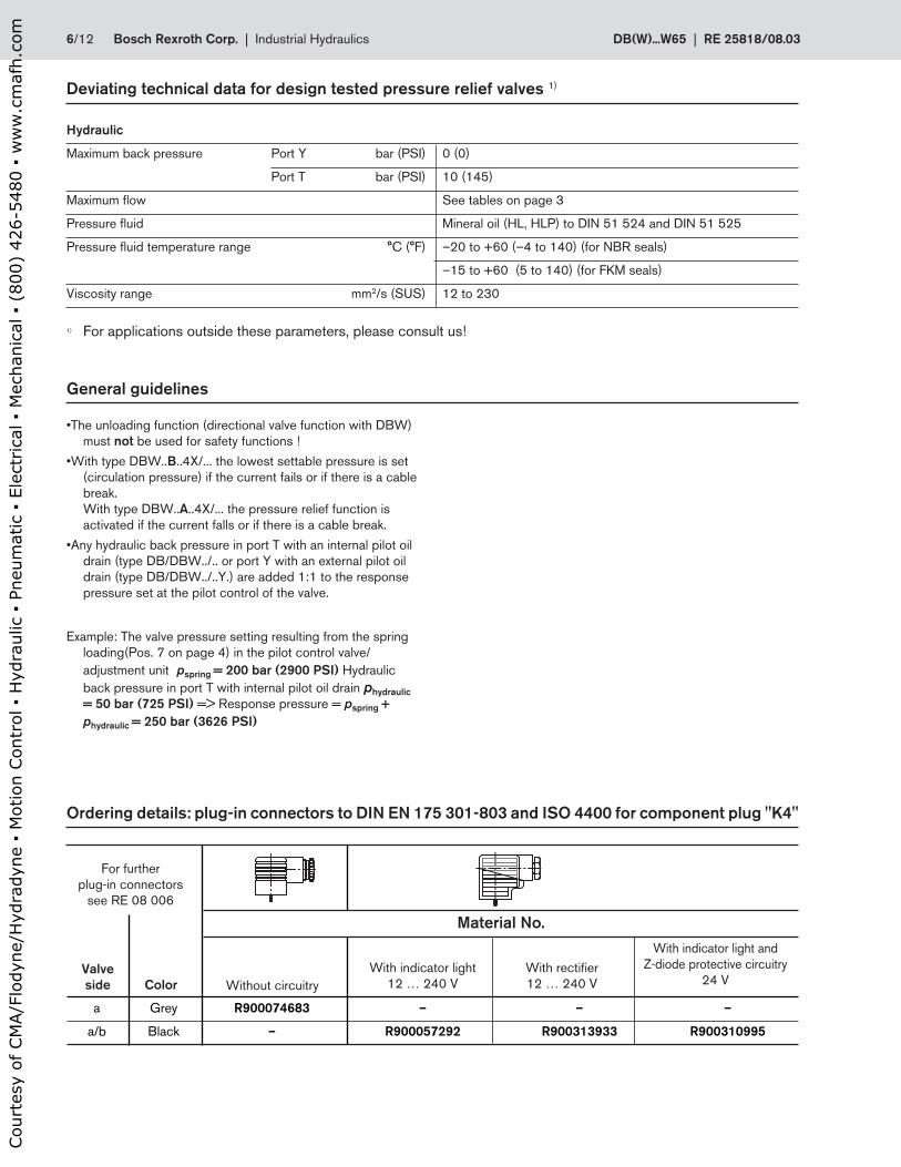
a Grey R900074683 – – –
a/b Black – R900057292 R900313933 R900310995
With indicator light and
Z-diode protective circuitry
24 VWith rectifi er
12 … 240 V
With indicator light
12 … 240 V
Ordering details: plug-in connectors to DIN EN 175 301-803 and ISO 4400 for component plug "K4"
Valve
side Color
Material No.
For further
plug-in connectors
see RE 08 006
Without circuitry
Hydraulic
Maximum back pressure Port Y bar (PSI) 0 (0)
Port T bar (PSI) 10 (145)
Maximum fl ow See tables on page 3
Pressure fl uid Mineral oil (HL, HLP) to DIN 51 524 and DIN 51 525
Pressure fl uid temperature range °C (°F) –20 to +60 (–4 to 140) (for NBR seals)
–15 to +60 (5 to 140) (for FKM seals)
Viscosity range mm2/s (SUS) 12 to 230
Deviating technical data for design tested pressure relief valves 1)
1) For applications outside these parameters, please consult us!
General guidelines
• The unloading function (directional valve function with DBW)
must not be used for safety functions !
• With type DBW..B..4X/... the lowest settable pressure is set
(circulation pressure) if the current fails or if there is a cable
break.
With type DBW..A..4X/... the pressure relief function is
activated if the current falls or if there is a cable break.
• Any hydraulic back pressure in port T with an internal pilot oil
drain (type DB/DBW../.. or port Y with an external pilot oil
drain (type DB/DBW../..Y.) are added 1:1 to the response
pressure set at the pilot control of the valve.
Example: The valve pressure setting resulting from the spring
loading (Pos. 7 on page 4) in the pilot control valve/
adjustment unit pspring = 200 bar (2900 PSI) Hydraulic
back pressure in port T with internal pilot oil drain phydraulic
= 50 bar (725 PSI) => Response pressure = pspring +
phydraulic = 250 bar (3626 PSI)
Cou
rtes
y of
CM
A/F
lody
ne/H
ydra
dyne
▪ M
otio
n Con
trol
▪ H
ydra
ulic
▪ P
neum
atic
▪ E
lect
rica
l ▪ M
echa
nica
l ▪ (
800)
426
-548
0 ▪
ww
w.c
maf
h.co
m
RE 25818/08.03 | DB(W)...W65 Industrial Hydraulics | Bosch Rexroth Corp. 7/12
0 50 100 150 200 250 300
1 2
5(72)
10(145)
15(217)
(13.2) (26.4) (39.6) (52.8) (66) (79)
0 50 100 150 200 250 300
1 2
(13.2) (26.4) (39.6) (52.8) (66) (79)
5(72)
10(145)
15(217)
0 50 100 150 200 4250 300 350
1 3
( ) ( ) ( ) ( ) ( ) ( ) ( ) (
5(72)
10(145)
15(217)
0 50 100 150 200 400
5(72)
10(145)
15(217)
250 300 350
1 3
(13.2) (26.4) (39.6) (52.8) (66) (79) (92.4) (105.6)
0 50 100 150 200 400
50(725)
100(1450)
150(2175)
200(2900)
250(3626)
300(4351)
350(5076)
400(5801)
250 300 350
1 2
(13.2) (26.4) (39.6) (52.8) (66) (79) (92.4) (105.6)
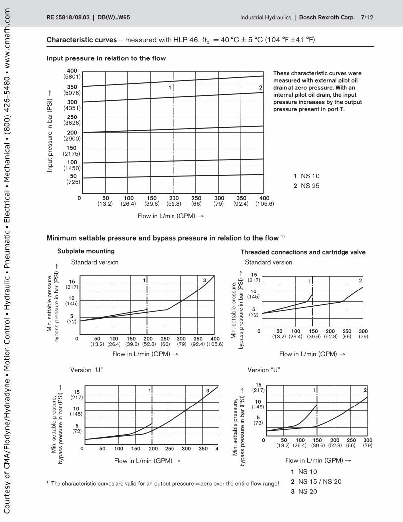
Characteristic curves – measured with HLP 46, ϑoil = 40 °C ± 5 °C (104 °F ±41 °F)
Input pressure in relation to the fl ow
Flow in L/min (GPM) →
Inp
ut
pre
ssure
in b
ar
(PS
I) →
These characteristic curves were
measured with external pilot oil
drain at zero pressure. With an
internal pilot oil drain, the input
pressure increases by the output
pressure present in port T.
1 NS 10
2 NS 25
Minimum settable pressure and bypass pressure in relation to the fl ow 1)
Subplate mounting Threaded connections and cartridge valve
Standard version Standard version
Version “U”Version “U”
Min
. sett
ab
le p
ressure
,
byp
ass p
ressure
in b
ar
(PS
I) →
1 NS 10
2 NS 15 / NS 20
3 NS 20
1) The characteristic curves are valid for an output pressure = zero over the entire fl ow range!
Flow in L/min (GPM) →
Min
. sett
ab
le p
ressure
,
byp
ass p
ressure
in b
ar
(PS
I) →
Flow in L/min (GPM) →
Min
. sett
ab
le p
ressure
,
byp
ass p
ressure
in b
ar
(PS
I) →
Min
. sett
ab
le p
ressure
,
byp
ass p
ressure
in b
ar
(PS
I) →
Flow in L/min (GPM) →Flow in L/min (GPM) →
Cou
rtes
y of
CM
A/F
lody
ne/H
ydra
dyne
▪ M
otio
n Con
trol
▪ H
ydra
ulic
▪ P
neum
atic
▪ E
lect
rica
l ▪ M
echa
nica
l ▪ (
800)
426
-548
0 ▪
ww
w.c
maf
h.co
m
8/12 Bosch Rexroth Corp. | Industrial Hydraulics DB(W)...W65 | RE 25818/08.03
41
(1
.61
4)
12
1 (
4.7
6)
42.5 (1.673)37.5 (1.476)
125 (0.197) 12
12
22.1 (0.87)
47.5 (1.87)
53.8 (2.118)
53
.8 (
2.1
18
)
78
(3
.07
)
78 (3.07)5 (0.2)5
(0
.2)
26
(1
.02
4) 73
(2
.87
4)
48
(1
.89
)
Ø6 (0.236)
Ø32 (1.26)
18
(0
.7)
10
0 (
3.9
4)
76
(2
.99
)
40
(1
.57
)
4 x Ø14 (0.551)
X P T
X Y
3
8 29 0 1
Ø30 (1.18)
Ø35 (1.378)
8
10
14
2; 16
13
12
3
1
15
7
9
4
12
11
6
5
5 (0.197)
(0.47) (0.47)
(0.47)
G 1
/4
(SA
E-4
; 7
/1
6-2
0)
G 1
/4
(SA
E-4
; 7
/1
6-2
0)
0.0004/4.0 in
0.01/100 mm
(Rmax 4)
Required surface fi nish of
the mating piece
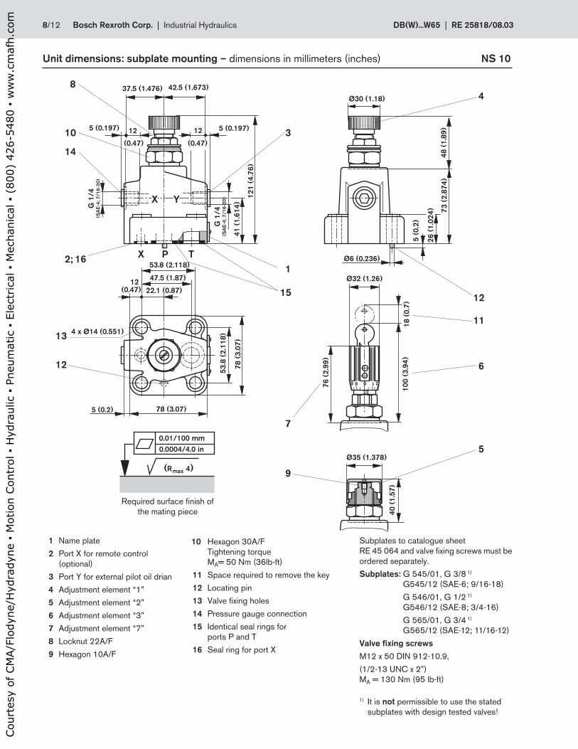
1 Name plate
2 Port X for remote control
(optional)
3 Port Y for external pilot oil drian
4 Adjustment element “1”
5 Adjustment element “2”
6 Adjustment element “3”
7 Adjustment element “7”
8 Locknut 22A/F
9 Hexagon 10A/F
Subplates to catalogue sheet
RE 45 064 and valve fi xing screws must be
ordered separately.
Subplates: G 545/01, G 3/8 1)
G545/12 (SAE-6; 9/16-18)
G 546/01, G 1/2 1)
G546/12 (SAE-8; 3/4-16)
G 565/01, G 3/4 1)
G565/12 (SAE-12; 11/16-12)
Valve fi xing screws
M12 x 50 DIN 912-10.9,
(1/2-13 UNC x 2”)
MA = 130 Nm (95 lb-ft)
1) It is not permissible to use the stated
subplates with design tested valves!
10 Hexagon 30A/F
Tightening torque
MA= 50 Nm (36lb-ft)
11 Space required to remove the key
12 Locating pin
13 Valve fi xing holes
14 Pressure gauge connection
15 Identical seal rings for
ports P and T
16 Seal ring for port X
Unit dimensions: subplate mounting – dimensions in millimeters (inches) NS 10
Cou
rtes
y of
CM
A/F
lody
ne/H
ydra
dyne
▪ M
otio
n Con
trol
▪ H
ydra
ulic
▪ P
neum
atic
▪ E
lect
rica
l ▪ M
echa
nica
l ▪ (
800)
426
-548
0 ▪
ww
w.c
maf
h.co
m

RE 25818/08.03 | DB(W)...W65 Industrial Hydraulics | Bosch Rexroth Corp. 9/12
69 (2.71)
5 (
0.1
97
)
69
.5 (
2.7
36
) 4
8 (
1.8
9)
3
8 29 0 1
Ø32 (1.26)
18
(0
.7)
10
0 (
3.9
4)
76
(2
.99
)
23.8 (0.937) 11.1 (0.437)
55.6 (2.189)
4 x Ø18
26
(1.0
24)
Ø6 (0.236)
37
(1
.45
)
11
7.5
(4
.62
)
12 (0.47) 5 (0.197)
X Y
X P T
66.7 (2.626) 33.5 (1.319)
97 (3.82)
18.5 (0.73)
33.4
(1.315)
70
(2
.75
6)
10
0 (
3.9
4)
Ø30 (1.18)
40
(1
.57
) Ø35 (1.378)
3
8
10
14
2; 16
13
12
1
15
7
9
4
12
11
6
5
5 (0.197) 12
(0.47)
(Ø0.709)
G 1
/4
(SA
E-4
; 7
/1
6-2
0)
G 1
/4
(SA
E-4
; 7
/1
6-2
0)
0.0004/4.0 in
0.01/100 mm
(Rmax 4)
Required surface fi nish of the mating piece
Unit dimensions: subplate mounting – dimensions in mm (inches) NS 25
1 Name plate
2 Port X for remote control (optional)
3 Port Y for external pilot oil drain
4 Adjustment element “1”
5 Adjustment element “2”
6 Adjustment element “3”
7 Adjustment element “7”
8 Locknut 22A/F
9 Hexagon 10A/F
Subplates to catalogue sheet
RE 45 064 and valve fi xing screws must
be ordered separately.
Subplates G 408/01, G 3/4 1)
G408/12 (SAE-12; 11/16-12)
G 409/01, G 1 1)
G409/12 (SAE-16; 15/16-20)
Valve fi xing screws
M16 x 50 DIN 912-10.9,
(5/8-11 UNC x 2”)
MA = 310 Nm (228 lb-ft)
1) It is not permissible to use the stated
subplates with design tested valves!
10 Hexagon 30A/F Tightening torque MA= 50 Nm (36 lb-ft)
11 Space required to remove the key
12 Locating pin
13 Valve fi xing screws
14 Pressure gauge connection
15 Identical seal rings for ports P and T
16 Seal ring for port X
Cou
rtes
y of
CM
A/F
lody
ne/H
ydra
dyne
▪ M
otio
n Con
trol
▪ H
ydra
ulic
▪ P
neum
atic
▪ E
lect
rica
l ▪ M
echa
nica
l ▪ (
800)
426
-548
0 ▪
ww
w.c
maf
h.co
m
10/12 Bosch Rexroth Corp. | Industrial Hydraulics DB(W)...W65 | RE 25818/08.03
3
82
90
1
Ø3
2 (
1.2
6)
18 (0.7)
100 (3.94)
76 (2.99)
33
(1.2
29
)4
2(1
.65
4)
75
(2
.95
3)
=
66
(2
.59
8)
66 (2.598)
35 (1.378)
169 (6.65)
48
201.8
2.5 (0.098)
Ø9 (0.35)
48
(1
.89
)
44.5 (1.75) 45 (1.77)
121 (4.77)
ØD2; 0.3
D1
ØD2; 0.3
D1
Ø25 (0.984)
T
P
P X
ØD2; 0.3
D1
Ø25 (0.984)
Y
41 45
90 (3.54)
35 (1.378) 31 (1.22)
= Ø3
0 (
1.1
8)
40 (1.57)
Ø3
5 (
1.3
8)
13
19
1
24
4
8
10
3
17
2
7
11
65
9
20 25
85
.5 (
3.3
6)
15
(0
.6)
()
91
.5 (
98
)Pg 11Pg 11
18
1
3.5 (0.137)
A
14 (0.55) 22
21
23
25
P
TB 26
28
29
28
29
27
50.5
(1.98)
(1.89)
(1.61) (1.77)
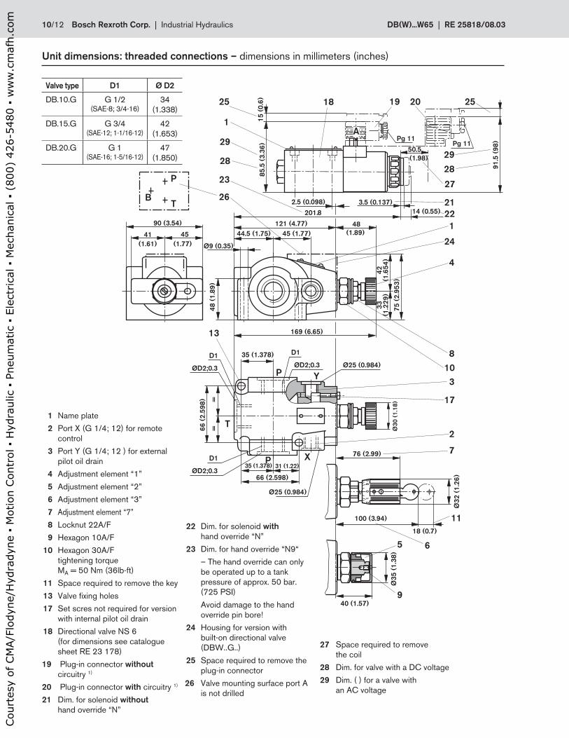
Unit dimensions: threaded connections – dimensions in millimeters (inches)
1 Name plate
2 Port X (G 1/4; 12) for remote
control
3 Port Y (G 1/4; 12 ) for external
pilot oil drain
4 Adjustment element “1”
5 Adjustment element “2”
6 Adjustment element “3”
7 Adjustment element “7”
8 Locknut 22A/F
9 Hexagon 10A/F
10 Hexagon 30A/F
tightening torque
MA = 50 Nm (36lb-ft)
11 Space required to remove the key
13 Valve fi xing holes
17 Set scres not required for version
with internal pilot oil drain
18 Directional valve NS 6
(for dimensions see catalogue
sheet RE 23 178)
19 Plug-in connector without
circuitry 1)
20 Plug-in connector with circuitry 1)
21 Dim. for solenoid without
hand override “N”
22 Dim. for solenoid with
hand override “N”
23 Dim. for hand override “N9“
– The hand override can only
be operated up to a tank
pressure of approx. 50 bar.
(725 PSI)
Avoid damage to the hand
override pin bore!
24 Housing for version with
built-on directional valve
(DBW..G..)
25 Space required to remove the
plug-in connector
26 Valve mounting surface port A
is not drilled
27 Space required to remove
the coil
28 Dim. for valve with a DC voltage
29 Dim. ( ) for a valve with
an AC voltage
Valve type D1 Ø D2
DB.10.G G 1/2(SAE-8; 3/4-16)
34
(1.338)
DB.15.G G 3/4(SAE-12; 1-1/16-12)
42
(1.653)
DB.20.G G 1(SAE-16; 1-5/16-12)
47
(1.850)
Cou
rtes
y of
CM
A/F
lody
ne/H
ydra
dyne
▪ M
otio
n Con
trol
▪ H
ydra
ulic
▪ P
neum
atic
▪ E
lect
rica
l ▪ M
echa
nica
l ▪ (
800)
426
-548
0 ▪
ww
w.c
maf
h.co
m
RE 25818/08.03 | DB(W)...W65 Industrial Hydraulics | Bosch Rexroth Corp. 11/12
3
8 29 0 1
18
(0
.7)
10
0 (
3.9
4)
76
(2
.99
)
40
(1
.57
)
48
(1
.89
)
11
2.5
(4
.43
)Ø32 (1.26)
Y
X
Ø30 (1.18)
Ø35 (1.38)
4
5
9
8
10
26323127
28
29
30
7
11
6
Ø29H8
Y
M28 x 1.5
20°
A Ø21H8
2.5
(0
.09
8)
8 (
0.3
15
)19 (
0.7
48)
64
(2
.52
)
70
(2
.75
6)
Ø3
0 1)
37
(1
.45
7)
Ø15.5
P
T
B
Y
2
Ø29H8
Z
Y
Ø3
0 (
1.1
81
)1
)
M28 x 1.5
Ø26.5(1.043)
20°
Y
Z
A0.03(0.0012)
Z
20°A
Y
Ø22.5 (0.88 )H8
Ø30 1)
Y
X
Ø4
(0
.15
7)
Ø2.5
(0.0
98)
18 (
0.7
09)
31
.5 (
1.2
4)
42
(1
.65
3)
64
.5+
1.5
66
(2
.59
8)
T
PP
Ø3
0 1
)
B
8 (
0.3
15
)
48
(1
.89
)10° +0
.2+0
.2
33
34
35
36
33
34
33
Ø24+0.1
20°
Z
Z
Z
20°
B0.03 A
(Ø1.043)
37
(2.5
39
)
(Ø1
.18
1)
0.03(0.0012) B
H8(1.142 )
(0.945 )+0.0039
(Ø1.181)
Ø21H8
(0.828 )H8
H8
Ø1
2 (
0.4
72
)
Ø30 (1.188)
0.03(0.0012)
2.5
(0.0
98)
19
(0
.74
8)
28.5
(1
.122 )
+0
.00
8
35 (1
.378 )
+0
.2
+0
.00
8
56 (2
.205 )
+0
.00
8
+0
.2
64.5
(2
.539 )
+0
.2+
0.0
08
54 (2
.126 )
+0
.2+
0.0
08
56 (2
.205 )
+0
.2+
0.0
08
Ø1.142H8
Ø0.828H8
(0
.18
1)
A
(0.079)
(Ø0.61)
Ø26.5
=Y
=ZR
z 16
Rz 8
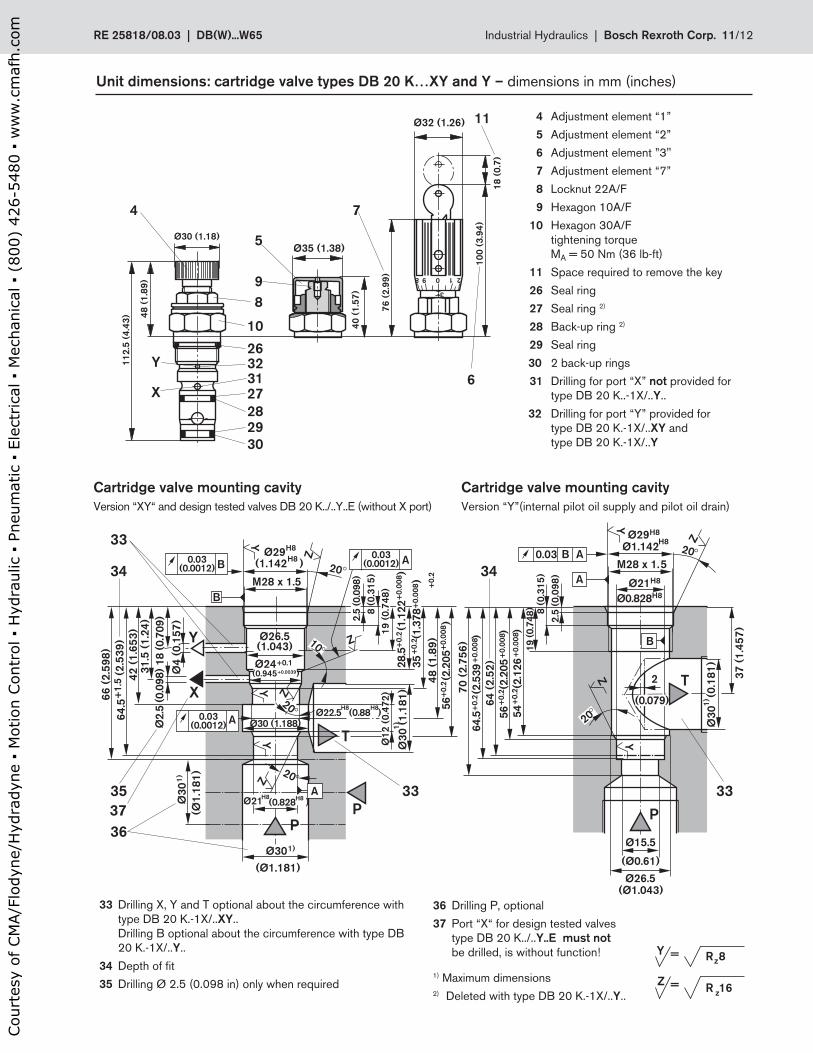
Unit dimensions: cartridge valve types DB 20 K…XY and Y – dimensions in mm (inches)
4 Adjustment element “1”
5 Adjustment element “2”
6 Adjustment element ”3"
7 Adjustment element “7”
8 Locknut 22A/F
9 Hexagon 10A/F
10 Hexagon 30A/F
tightening torque
MA = 50 Nm (36 lb-ft)
11 Space required to remove the key
26 Seal ring
27 Seal ring 2)
28 Back-up ring 2)
29 Seal ring
30 2 back-up rings
31 Drilling for port “X” not provided for
type DB 20 K..-1X/..Y..
32 Drilling for port “Y” provided for
type DB 20 K.-1X/..XY and
type DB 20 K.-1X/..Y
1) Maximum dimensions
2) Deleted with type DB 20 K.-1X/..Y..
Cartridge valve mounting cavity
Version “Y”(internal pilot oil supply and pilot oil drain)
Cartridge valve mounting cavity
Version “XY“ and design tested valves DB 20 K../..Y..E (without X port)
33 Drilling X, Y and T optional about the circumference with
type DB 20 K.-1X/..XY..
Drilling B optional about the circumference with type DB
20 K.-1X/..Y..
34 Depth of fi t
35 Drilling Ø 2.5 (0.098 in) only when required
36 Drilling P, optional
37 Port “X“ for design tested valves
type DB 20 K../..Y..E must not
be drilled, is without function!
Cou
rtes
y of
CM
A/F
lody
ne/H
ydra
dyne
▪ M
otio
n Con
trol
▪ H
ydra
ulic
▪ P
neum
atic
▪ E
lect
rica
l ▪ M
echa
nica
l ▪ (
800)
426
-548
0 ▪
ww
w.c
maf
h.co
m
12/12 Bosch Rexroth Corp. | Industrial Hydraulics DB(W)...W65 | RE 25818/08.03
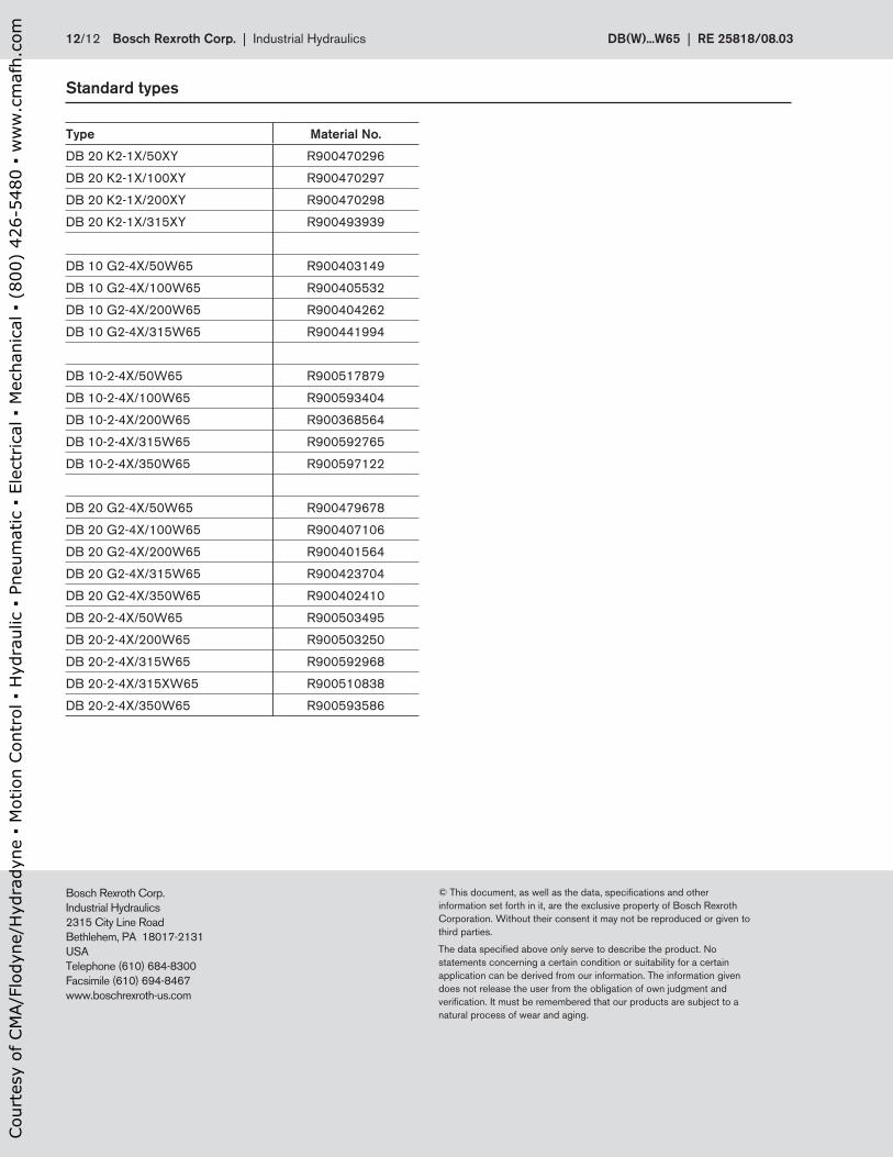
Standard types
Type Material No.
DB 20 K2-1X/50XY R900470296
DB 20 K2-1X/100XY R900470297
DB 20 K2-1X/200XY R900470298
DB 20 K2-1X/315XY R900493939
DB 10 G2-4X/50W65 R900403149
DB 10 G2-4X/100W65 R900405532
DB 10 G2-4X/200W65 R900404262
DB 10 G2-4X/315W65 R900441994
DB 10-2-4X/50W65 R900517879
DB 10-2-4X/100W65 R900593404
DB 10-2-4X/200W65 R900368564
DB 10-2-4X/315W65 R900592765
DB 10-2-4X/350W65 R900597122
DB 20 G2-4X/50W65 R900479678
DB 20 G2-4X/100W65 R900407106
DB 20 G2-4X/200W65 R900401564
DB 20 G2-4X/315W65 R900423704
DB 20 G2-4X/350W65 R900402410
DB 20-2-4X/50W65 R900503495
DB 20-2-4X/200W65 R900503250
DB 20-2-4X/315W65 R900592968
DB 20-2-4X/315XW65 R900510838
DB 20-2-4X/350W65 R900593586
Bosch Rexroth Corp.
Industrial Hydraulics
2315 City Line Road
Bethlehem, PA 18017-2131
USA
Telephone (610) 684-8300
Facsimile (610) 694-8467
www.boschrexroth-us.com
© This document, as well as the data, specifi cations and other
information set forth in it, are the exclusive property of Bosch Rexroth
Corporation. Without their consent it may not be reproduced or given to
third parties.
The data specifi ed above only serve to describe the product. No
statements concerning a certain condition or suitability for a certain
application can be derived from our information. The information given
does not release the user from the obligation of own judgment and
verifi cation. It must be remembered that our products are subject to a
natural process of wear and aging.
Cou
rtes
y of
CM
A/F
lody
ne/H
ydra
dyne
▪ M
otio
n Con
trol
▪ H
ydra
ulic
▪ P
neum
atic
▪ E
lect
rica
l ▪ M
echa
nica
l ▪ (
800)
426
-548
0 ▪
ww
w.c
maf
h.co
m