press fitting systems technical handbook - · pdf file4.6 equipment installations in...
TRANSCRIPT

Press fitting systemsTechnical Handbook
English
January 2015
Technical Handbook
This version of the technical handbook replaces all previous editions
Paese Ente Numero certificato Dimensioni
DW-8511AU2084(W 534) Oslash 15 - 108 mm
DW-7301 BM3426(GW 541) Oslash 15 - 108 mm
G 4060006(VdS 2344 - VdS 2100) Oslash 22 - 761 mm
W 1402 (PW 300) Oslash 15 - 108 mm
0007-4278 (TPW 132) Oslash 15 - 108 mm
1209070 Oslash 15 - 108 mm
1300035 Oslash 15 - 108 mm
79 - 1600 Oslash 15 - 108 mm
38058A0 BV Oslash 15 - 108 mm
VA 12219224VA 11218410
Oslash 15 - 108 mmOslash 15 - 108 mm
117499 Oslash 15 - 108 mm
K4083403K4083503 Oslash 15 - 108 mm
P-14170 Oslash 15 - 108 mm
Nr 1623 Oslash 15 - 108 mm
POCCIT Д E01H 37816 Oslash 15 - 108 mm
TEST REPORT ZH 173 Oslash 15 - 108 mm
A-21562012 Oslash 15 - 108 mm
AT-15-78632008 Oslash 15 - 108 mm
STO-30-00061-10 Oslash 15 - 108 mm
MAC - 138111CS Oslash 15 - 108 mm
TIFQ - 0311R99 Oslash 15 ndash 108 mm
DAU 11 - 072 Oslash 15 - 108 mm
40141 - 40142 Oslash 15 - 108 mm
INO
XPRE
S
Paese Ente Numero certificato Dimensioni
DG-8531BP0295(VP 614) Oslash 15 - 54 mm
DG-8531CL0163(VP 614) Oslash 76 - 108 mm
G 2827(PG 500 PG 314) Oslash 15 - 54 mm
G 2827(PG 500 PG 314) Oslash 76 - 108 mm
05-088-06(VP 614) Oslash 15 - 54 mm
CA06-00231 Oslash 15 - 54 mm
POCCIT Д EO1H37816 Oslash 15 - 54 mm
A-7302010 Oslash 15 - 54 mm
DAU 11 - 072 Oslash 15 - 54 mm
STO-30-00300-10 Oslash 15 - 54 mmIN
OXP
RES
GA
S
79 - 1339 Oslash 15 - 108 mm
V1005A Oslash 15 - 108 mm
P-14170 Oslash 15 - 108 mm
POCCIT Д E01H37816 Oslash 15 - 108 mm
A-21562012 Oslash 15 - 108 mm
AT-15-78632008 Oslash 15 - 108 mm
DAU 11 - 073 Oslash 15 - 108 mm
B-30-00055-11 Oslash 15 - 108 mm
00261042011 Oslash 15 - 108 mm
STEE
LPRE
S
DW-8511CL0331 Oslash 15 - 54 mm
1209071 Oslash 15 - 54 mm
ndeg 1988 Oslash 15 - 54 mm
K8313601 Oslash 15 - 54 mm
AES
PRES
DG-8531CL0376 Oslash 15 - 54 mm
CA0600293 Oslash 15 - 54 mmAES
PRES
GA
S
MAC - 138111CS Oslash 15 - 108 mm
P - 13928 Oslash 15 - 108 mm
1300035 Oslash 15 - 108 mm
38059A0 BV Oslash 15 - 108 mm
MA
RIN
EPRE
S
G 408004 Oslash 22 - 54 mm
3034282 Oslash 22 - 54 mm
STEE
LPRE
S Vd
S-FM
3Technical Handbook
10 Introduction 511 Raccorderie Metalliche SpA 512 Press fitting systems in water heating and cooling installations 620 Press fitting systems 721 Connection technique - M profil 722 Inoxpres press fittings 723 Inoxpres Gas press fittings 824 Inoxpres piping 825 Steelpres press fittings 926 Steelpres piping 927 Aespres press fittings 1028 Aespres Gas press fittings 1029 Aespres - Aespres Gas copper piping 11210 Marinepres press fittings 12211 Marinepres piping 12212 Sealing elements 132121 Sealing ring profile 132122 Materials characteristics applications 13213 Pressing tools152131 Basic 152132 Equipment periodical service 152133 Sprinkler installations 1730 Areas of use 1831 Applications 20311 Potable water treated water water for extinguishing systems 20312 Heating 21313 Cooling and refrigeration circuits 21314 Compressed air and inert gas 21315 Natural Gas LPG installation 21316 Solar vacum steam condensation 22317 Industrial applications 22318 Shipbuilding 23319 Sprinkler installations 233110 Glycols for installation 2340 Processing 2441 Storage and transport 2442 Pipes-cutting to length deburring bending 2443 Marking the insertion depthstripping 2444 Press fitting seal ring check 2545 Making the press connection 2546 Equipment installations in AustraliaNew Zealand 26
Indice
4 Technical Handbook
47 Protection of pipelines and connections from external corrosion - general 2648 Minimum distances and space requirement for pressing 2849 Thread or flange connections 28 50 Planning 2951 Pipe fixings distances between clamps 2952 Expansion compensation 2953 Thermal emission 3354 Insulation 3455 Soundproofing (DIN 4109) 3556 Fire prevention 3557 Potential equalisation 3658 Dimensioning 3659 Trace heating 3660 Start-up 3761 Pressure testing 3762 Flushing the system and starting up 3763 Regular checks 3770 Corrosion 3871 Inoxpres38711 Bimetal corrosion (mixed installation) - DIN 1988 part 200 38712 Crevice pitting corrosion (three phase corrosion) 38713 Outside corrosion 3972 Inoxpres Gas 42721 Outside corrosion 4073 Steelpres 41731 Inside corrosion 41732 Bimetal corrosion 41733 Outside corrosion 4174 AespresMarinepres 42741 Bimetal corrosion (mixed installation) 42742 Perforating corrosion 42743 Outside corrosion 4275 Aespres Gas4380 Disinfection 4490 Hygiene 44100 Form Request of compatibility 45110 Pressure test protocol 46111 Pressure test protocol for drinking water systems in bdquowet conditionsrdquo 46112 Pressure test protocol for hot water heating systems 47113 Pressure test protocol for potable water with compressed air 48120 Guarantee 49
5Technical Handbook
Raccorderie Metalliche SpA (RM) was founded as a family company in the Mantova province of Italy in 1970 and is specialised in the production and distribution of sleeves fittings and elbows both in carbon steel and stainless steel and pipe fixing systems In 1999 the company introduced Inoxpres the press fitting system in stainless steel and later Steelpres the carbon steel press fitting system
Extensive investment in buildings and very modern machinery in operation ensure the current annual capacity of approximately 8 million press fittings The specialist sanitary and heating stockist trade within Europe together with selected non-European markets are supplied within the framework of the three-stage distribution set-up market support subsidiary companies exist in both Germany Austria and Spain
The company has a distinctive quality management system which has been certified in accordance with UNI EN ISO 90012008
The suitability of the Inoxpres and Steelpres press fitting systems described in this handbook for the applications defined has been- as far as required- tested and certified by WRAS the DVGW in Germany and a wide range of other international organisations
11 Raccorderie Metalliche SpA
10 Introduction
Figure 1 - Campitello head office and factory
Figure 2 - EN ISO 90012008 RM Certification
6 Technical Handbook
12 Press fitting systems in water heating and cooling installation
Press fittings made of steel and copper were developed in Sweden at the end of the fifties and have enjoyed an increasingly large share of the market since the beginning of the eighties in Europe The connection technique is still considered to be innovative since the tried-and-trusted simple lsquocoldrsquo mounting technique allows fast solid and permanent connection of tubing especially in domestic water gas and heating installations In the meantime the connection technique in the form of press fittings has spread to include not only all types of metal carbon steel stainless steel copper red bronze etc also plastic and plastic composite tubing and is in Europe the leading connection technique Raccorderie Metalliche SpA (RM) has furtherly developed carbon steel stainless steel and nowadays coppercopper-nickel press fitting range as well Besides It has clearly simplified the system assembly through the modification of our o-ring shape and toroidal chamberAt the same time the sealing surface has been enlarged and the risk of accidental non-pressing has been minimised by the creation of a security seal ring
With the Inoxpres press fitting system of stainless steel for potable water and gas installations Steelpres for closed hot water heating systems Aespres for potable water and gas installations Marinepres for naval sector RM offers a comprehensive shaped fitting series in the dimension range from 12-108 mm OD together with piping pressing tools and accessoriesTo simplify applications for the fitter the pressing of the fittings has been so constructed that all the tools approved from the press fitting systems leading manufacturers ie pressing tools and pressing jaws or collars are also approved by RMThe planning and installation of potable water and heating systems demands comprehensive expert knowledge together with knowledge of a multitude of industrial standards and technical guidelines This technical handbook is intended to provide especially planners and fitters with essential information to help both size up the field of application and to carry out professional installationThis handbook mostly refers to industrial standards and regulations which are valid in Germany Of particular importance are DIN 1988 part 100-600 the VDI guideline 6023 DIN EN 806 DIN EN 1717 DIN EN 12329 and the amendment to the potable water legislation (TrinkwV) which came into effect on the 1st January 2003 as well as DVGW work sheets W 534 and GW 541For supplementary information please contact the appropriate technical departments at Raccorderie Metalliche SpA Names addresses and further details can be found at the end of this handbook
Figure 3 - Product range
STAINLESS STEEL 14404 (AISI 316L)15 mm - 108 mm OD
GALVANISED CARBON STEEL12 mm - 108 mm OD
STAINLESS STEEL 14404 (AISI 316L)15 mm - 108 mm OD
COPPER-NICKEL15 mm - 108 mm OD
COPPER-BRONZE12 mm - 54 mm OD
COPPER-BRONZE15 mm - 54 mm OD
7Technical Handbook
21 Connection technique - M profil
The press connection is made by inserting the pipe into the press fitting as far as the marked insertion depth The connection is created by pressing using an approved pressing tool (see point 213 Pressing tools) The longitudinal and compression closing character of the connection is clearly illustrated in figures 4 and 5Press fittings in dimensions 12-35 mm must by pressed with jaws 42-108 mm must by pressed with pressing collarschainsDuring the pressing process a deformation takes place on two planesThe first plane creates a permanent connection and provides mechanical strength through the mechanical deformation of the press fitting and the pipe On the second plane the seal ring is deformed in its cross section and through its elastic properties creates the permanently tight joint
20 Press fitting systems
Figure 4 - Section through an Inoxpres Steelpres connection with jaw still in position Dimensions of 12 -35 mm produce a hexagonal pressing profile
Figure 5 - Section through an Inoxpres Steelpres connection with collar still in position Dimensions of 42-108 mm produce a defined profile
22 Inoxpres press fittings
Inoxpres press fittings are manufactured using high-alloyed austenitic stainless Cr-Ni-Mo steel with the material number 14404 (AISI 316 L)The press fittings are indelibly marked with laser reporting the manufacturer name diameter DVGW test symbol and internal code The formed ends of the press fittings are fitted with a black EPDM seal ring as standard for potable water applications
Figure 6 - Inoxpres press fitting
The complete range of the press fitting systems Inoxpres Steelpres Aespres and Marinepres is described in the relevant bdquoProduct rangerdquo catalogue
Section A-A
Pipe
Jaw
Press fitting
Mechanical strength
Seal ring
Tightness
Pipe
Mechanical strength
Seal ring
Tightness Section A-AKlauke
Section A-ANovopress
Jaw
Press fitting
8 Technical Handbook
23 Inoxpres Gas press fittings
Inoxpres Gas press fittings 15 - 108 mm outside diameter are tested in accordance with the requirements of the DVGW VP 614 guidelines and in Austria according to PG 500 and PG 314
They differ from Inoxpres for potable water installations in that they have a factory-fitted yellow NBRHNBR seal ring and are also indelibly marked Inoxpres in black and indelibly yellow marked with lsquoRMrsquo and the pressure range lsquoPN 5 GT 1rsquo
Figure 7 - Inoxpres Gas press fitting
24 Inoxpres pipingInoxpres pipes are longitudinally welded thin-walled tubes made of high alloyed austenitic stainless Cr-Ni-Mo steel with material number 14404 (AISI 316L) as well as tubes made of ferritic (laquonickel freeraquo) stainless steel with material number 14521 (AISI 444) The tubes correspond to worksheet GW 541 of the German Association for Gas and Water EN 10217-7 (DIN 17455) and EN 10312 and are therefore approved for drinking watergas (14404 AISI 316L) and only for drinking water (14521 AISI 444) Inner and outer surfaces are bare metal and free of annealing colours and corrosion-promoting substances Inoxpres pipes are classified as non-combustible pipes according to material class A they are supplied in lengths of 6 meters and are closed with plastic plugscaps at the ends
TABLE 1 INOXPRES PIPES - DIMENSIONS AND CHARACTERISTICS
Pipe outside diameterx wall thickness in
mm
Nominalwidth
DN
Pipe inside diameter in
mmMass in
kgmWater
volume inlm
15 x 10 12 13 0351 0133
18 x 10 15 16 0426 0201
22 x 12 20 196 0624 0302
28 x 12 25 256 0790 0514
35 x 15 32 32 1240 0804
42 x 15 40 39 1503 1194
54 x 15 50 51 1972 2042
761 x 2 65 721 3550 4080
889 x 2 80 849 4150 5660
108 x 2 100 104 5050 8490
Please contact RM for details regarding the use of Inoxpres Gas for gas applications in the UK
9Technical Handbook
25 Steelpres press fittings
Steelpres press fittings are made of unalloyed steel with
outer diameter A galvanic zinc coating with a thickness of 6divide12 μm protects against external corrosion Unlike the Inoxpres press fittings Steelpres fittings are indelibly marked in red with the manufacturer name diameter and internal code The black EPDM sealing ring used for Inoxpres is also fitted into the formed ends of the press fittings
26 Steelpres piping
Steelpres pipes are longitudinally welded thin-walled precision steel tubes according to DIN EN 10305-3The following materials are availablebull E 220 CR2S4 (material no 10215) pipes galvanised on the outside the zinc coating is 6divide12 μmbull E 190 CR2S4 (material no 10031) pipes are sendzimir-galvanised on both sides the zinc coating is 10divide20 μmThe weld seam is smoothed in order to ensure a proper sealing surface Steelpres pipes with PP ndash coat1 mm thick available in diameters ranging from 12 mm to 108 mm outer diameter (material E 220 CR2S4 - ndeg 10215) are classified in accordance with DIN 4102-1 building material class B2 - non-burning droplets Steelpres pipes are supplied in lengths of 6 meters
Figure 8 - Steelpres press fitting
TABLE 2 STEELPRES PIPES - DIMENSIONS AND CHARACTERISTICSPipe outside diameter
x wall thickness in mm
Nominal width
DN
Pipe inside diameter in
mmMass in
kgmWater
volume inlm
Pipe Outside diameter in
mmwithout PP-coating with PP coating
12 x 12 10 96 0320 0072 14
15 x 12 12 126 0408 0125 17
18 x 12 15 156 0497 0191 20
22 x 15 20 19 0824 0284 24
28 x 15 25 25 1052 0491 30
35 x 15 32 32 1320 0804 37
42 x 15 40 39 1620 1194 44
54 x 15 50 51 2098 2042 56
761 x 2 65 721 3652 4080 781
889 x 2 80 849 4290 5660 909
108 x 2 100 104 5230 8490 110
material number E 195 (material ndeg 10034) up to 108 mm
10 Technical Handbook
Aespres press fittings are made in DHP Cu-DHP 999 (CW024A) copper and in CuSn5Zn5Pb2 (CC499K) bronze from oslash 12 to oslash 54 mm included Aespres fittings are indelibly marked with a laser system with the manufacturer name the diameter and the DVGW control brand and with an internal code At the press fitting swollen ends a black EPDM o-ring is fittedIn Great Britain the Aespres system is certified with the WRAS quality brand from oslash 15 divide 54 mm
Aespres Gas press fittings 15 - 54 mm outside diameter are tested in accordance with the requirements of the DVGW VP 614 guidelinesThey are different from da Aespres (drinkable water system version) for the following featuresbull NBR yellow o-ring fitted at the end of productionbull the yellow indelible marking with RM Gas and pressure field PN 5GT1 next to the Aespres brand In Germany for gas systems compliance is to be provided to TRGI
27 Aespres press fittings
28 Aespres Gas press fittings
Figure 9 - Aespres press fitting
Figure 10 - Aespres Gas press fitting
TABLE 3 CHOICE OF STEELPRES - TUBES
316005galvanised on the outside black inside
316003galvanised on the outside black inside + PP ndash coating
316002galvanised insideoutside
Dimensions oslash 12 divide 108 mm Dimensions oslash 12 divide 108 mm Dimensions oslash 22 divide 54 mm
Heating
Solar
Compressed air
Inert gases
Heating
Cooling
Wet sprinkler systemoslash 22 divide 54 mm VdS-FM-certified
(water system)
Compressed air
Inert gases
11Technical Handbook
Piping for copper water and gas installation should comply with the standard UNI EN 10572010 ldquoCopper and copper alloys - Round tubes in copper without welding for water and gas in health-care and heating applicationsrdquo
Tube sizes to be used with Aespres and Aespres Gas press fittings are inluceded in the annexet table
29 Aespres - Aespres Gas copper piping
TABLE 4 MECHANICAL FEATUEES FOR COPPER TUBES - EN 1057
Rif EN 1173 State Minimum traction resistanceRm (Mpa)
R220 Ricotto 220
R250 Semiduro 250
R290 Duro 290
Breaking A dilationRif EN 1173 oslash (mm) A min ()
R220 12divide22 40
R250 12divide28 30
R290 12divide54 30
Stato di fornituraR220 Annealed Rolls
R250 Semi-hard Bars
R290 Hard Bars
TABLE 5 AESPRES PIPES - DIMENSIONS AND CHARACTERISTICS - EN 1057 DVGW GW 392Pipe outside diameter
x wall thickness in mm
Nominalwidth
DN
Pipe inside diameter in
mmMass in
kgmWater
volume inlm
Supplied condition
12x1 10 10 0309 0079 Roll 2550 m(R 220)
orBar 5 m(R 250)
15x1 12 13 0393 0133
18x1 15 16 0477 0201
22x1 20 20 0589 0314
28x15 25 25 1115 0491 Bar 5 m (R250)
35x15 32 32 1410 0804
Bar 5 m (R290)42x15 40 39 1704 1194
54x2 50 50 2918 1963
12 Technical Handbook
Marinepres press fitting are made in CuNi10Fe16Mn(WL 21972) copper-nickel from oslash 15 to oslash 108 mm includedMarinepress fittings are indelibly marked with a laser system with the manufacturer name the diameter and the DVGW control brand and with an internal code At the press fitting swollen ends a green FKM o-ring is fitted
210 Marinepres press fittings
Figure 11 - Marinepres press fitting
Marinepres piping with thin walls longitudinally welded are in CuNi10Fe16Mn copper-nickel Tubes in copper-nickel are made in compliance with the standard DIN 86019 Internal and external surfaces are in plain metal with no substance leading to corrosion Marinepres tubes are classified as non combustible belonging to class A as fire reaction They are supplied in 6 m long bars
211 Marinepres piping
TABLE 6 MARINEPRES PIPES - DIMENSIONS AND CHARACTERISTICS
Pipe outside diameterx wall thickness in
mm
Nominalwidth
DN
Pipe inside diameter in
mmMass in
kgmWater
volume inlm
15x1 12 13 0392 0133
18x1 15 16 0476 0201
22x1 20 20 0588 0314
28x15 25 25 1114 0491
35x15 32 32 1408 0804
42x15 40 39 1702 1195
54x15 50 51 2206 2043
761x2 65 721 4146 4072
889x2 80 849 4874 5675
108x25 100 103 7389 8332
13Technical Handbook
2121 Sealing ring profile
2122 Materials characteristics applications
Traditional press fitting systems use round sealing rings which can easily be damaged by careless fitting RM on the other hand uses a patented sealing ring with a lenticular profile which fits the press crimp grooveThis provides the following advantages
bull a 20 enlargement of the sealing surface areabull Major reduction of the risk of the sealing ring being pressed out or damagedbull fit makes the pipes insertion easier
The black EPDM sealing ring from 15 - 54 mm is supplied with an additional safety feature that during pressure tests will lead to leakage in the case of accidentally unpressed connections
212 Sealing elements
Figure 12 - Sealing ring profile
Figure 13 - Security EPDM sealing ring (oslash 15 divide 54 mm)
Press fitting systems were originally developed for use in potable water and heating installations and were fitted with a single standardised sealing ring for these applicationsAdditional fields of application such as gas and solar have been added through the use of stainless steel material at the same time motivating the development of sealing rings suitable for these applicationsRM supplies four different sealing rings their characteristics and fields of application are shown in table 7
The black EPDM standard sealing ring only is factory-fitted in the siliconised version in Inoxpres and Steelprespress fittings The green FKM sealing ring only is factory-fitted in Marinepres press fittings
+ 20 enlargementof sealing surface area
14 Technical Handbook
With the exception of potable water heating solar compressed air and gas the figures in the table above are only for guidance examination and approval by RM of each individual situation is therefore required
TABLE 7 SEALING RINGS - FIELDS OF APPLICATION AND TECHNICAL DATA
Technical term Colour
Operating temperaturemin - max
degrees centigrade
Operating pressure
maximumin bar
Approvalsand
certification basis
Fieldsof application
Factory-fitted
EPDMblack
-20deg+120deg 16KTW
W 270DVGW W 534
Potable waterHeating
Cooling and refrigeration circuitsTreated water
Desalinated waterRainwater
Compressed air(Class 1divide4)
YES
NBRHNBR
yellow -20deg+70deg 5 G 260HTBDVGW VP 614
Natural gasMethane gas
GPL (gaseous state)YES
FKMgreen
-20deg+220deg 16 -
SolarCompressed air
(Class 5)Naval
YES(for Marinepres)
MVQred
-20deg+180deg 16 -Industrial applications
following approvalby RM
NO
15Technical Handbook
Pressing tools basically consist of the pressing machine (= drive machine) and pressing jaws or collarschainsMany of the pressing jawscollars can generally be used with the pressing machines from one manufacturer Additionally many manufacturers of pressing tools have so standardised the jaw attachment that pressing jaws from other manufacturers can also be used
Principally all metallic press fitting systems have a pressing contour on the press fittings which matches the profile of the pressing jawscollars For this reason it is necessary to have the approval of the tooling by the manufacturer of the press fittings intended for use In addition it is important to follow exactly the maintenance and servicing instructions issued by the pressing tool manufacturer
213 Pressing tools
RM approves the tools produced by Klauke and Novopress listed in the tables 8 and 9 belowThese are pressing tools with the appropriate pressing jaws or collarschains
Figure 14 - Klauke UAP3L Figure 16 - Novopress ACO202 Figure 17 - Novopress ACO401Figure 15 - Klauke UAP100L
2131 Basics
2132 Approved pressing tools
TABLE 8 MANUFACTURER KLAUKE
Type Pistonstrength
Dimensionrange Weight Compatible with jaws from
MAP1 15 KN 15 divide 22 mm ~ 25 Kg Not compatible
UAP2 - UAP3L 32 KN 12 divide 54 mm ~ 35 Kg NovopressEFP2 EFP201 AFP201 EFP202 AFP202 ECO 1 ACO 1
UNP2 32 KN 12 divide 54 mm ~ 35 Kg NovopressEFP2 EFP201 AFP201 EFP202 AFP202 ECO 1 ACO 1
UAP4 - UAP4L 32 KN 12 divide 54 mm PN16761 divide 108 mm PN10 ~ 43 Kg
NovopressEFP2 EFP201 AFP201 EFP202 AFP202 ECO 1 ACO 1
12 divide 54 mm
UAP100 - UAP100L 120 KN 761 divide 108 mm ~ 127 Kg Not compatible
AHP700LS
PKUAP3 32 KN 12 divide 54 mm ~ 123 Kg NovopressEFP2EFP201AFP201 EFP202AFP202 ECO 1 ACO 1
12 divide 54 mmPKUAP4 32 KN 12 divide 54 mm PN16761 divide 108 mm PN10 ~ 126 Kg
PK100AHP 120 KN 761 divide 108 mm ~ 202 Kg Not compatible
EHP2SANB 075 KW 761 divide 108 mm ~ 28 Kg Not compatible
16 Technical Handbook
The Novopress ECO 301 and ACO 202XL pressing tools are not approved for the king size dimensions76 divide 108 mm Inoxpres Gas fittings in sizes 76 divide 108 mm must be pressed with pressing collarschains and UAP100UAP100LACO401 pressing machine only (others pressing machines are not approved)
With regard to the Klauke pressing tool UAP4UAP4L the limitation on PN 10 is to be observed for the king-size dimensions 76-108 mm outer diameter
TABLE 9 MANUFACTURER NOVOPRESS
Type Pistonstrength
Dimensionrange Weight Compatible with jaws from
EFP2 32 KN 15 divide 54 mm ~ 61 Kg EFP 201 AFP201 ECO 1 ACO 1
EFP201EFP202 32 KN 15 divide 54 mm ~ 44 Kg EFP 2 ECO 1 ACO 1
AFP201AFP202 32 KN 15 divide 54 mm ~ 43 Kg EFP 2 ECO 1 ACO 1
ECO 202ACO202 32 KN 15 divide 54 mm ~ 33 Kg ECO201 ACO 201 ECO1 ACO1
ACO 202XL 32 KN 15 divide 54 mm ~ 46 Kg ECO202 ACO 202
ACO401 100 KN 761 divide 108 mm ~ 13 kg Not compatible
ACO 3 36 KN 15 divide 54 mm ~ 50 Kg ECO 3
ECO 301 45 KN 15 divide 54 mm ~ 50 Kg ACO 3
HCP 190 KN 761 divide 108 mm ~ 14-16 Kg Not compatible
17Technical Handbook
Jaw and chain pressing units are to be serviced for a correct joint production They are to be serviced at least once a year or after 900 working hour by an authorized dealer What is more any moving part (drive rolls) and pressing jaw and chain surfaces (internal profiles) are to be daily serviced cleaned and lubricated
Any possible oxidation paint or dirt in generally affect the tool reliability leading to equipment sliding problems on joints during pressing
2133 Periodical equipment service
Keep the pins lubricated with oilKeep the chain clean Keep the pins lubricated with grease Attention it can be broken
Figure 18 - Klauke equipment Figure 19 - Novopress equipment
18 Technical Handbook
30 Areas of use
TABLE 10 FIELD OF APPLICATION FOR PRESS FITTING SYSTEMS INOXPRES STEELPRES AESPRES
Application System O-ring Notes PN max(barg) T degC
Drinking water
Inoxpres(pipe AISI 316L o Type 444) EPDM black - 16 0deg +120degC
Aespres(copper pipe table 4-5) EPDM black - 16 0deg +120degC
Heating
Steelpres(pipe 316005) EPDM black
Only use internally black pipesPaying particularly attention to the external
protection against corrosion by using a PP covered Pipe + primer (paint) bandage
16 0deg +120degC
Inoxpres EPDM black - 16 0deg +120degC
Aespres(copper pipe table 4-5) EPDM black - 16 0deg +120degC
Extinguishingwater (1) Inoxpres (2) EPDM black Dal oslash 22 divide 76 mm
(VdS certified) 125 Room temperature
(1) The certifications VdS define a possible use for extinguishing water Please contact RM for verification (2) For joints 22-54 mm use presses whose driving force accounts for 32 KN For King size fittings (76 mm) use presses whose driving force accounts for 100 KN
Sprinkler system (3)
Inoxpres (4)(pipe AISI 316L) EPDM black Dim oslash 22 divide 76 mm (VdS certified)
(wet and dry) 125 Room temperature
Steelpres VdS-FM (4)(pipe 316002) MVQ red
Dim oslash 22 divide 54 mm (VdS-FM certified) useexternalinternal galvanized pipe
(wet)16 Room
temperature
(3) The certifications VdS-FM define a possible use for sprinkler systems Please contact RM for verification(4) For joints 22-54 mm use presses whose driving force accounts for 32 KN For King size fittings (76 mm) use presses whose driving force accounts for 100 KN
Cooling
Inoxpres EPDM black - 16 -20deg +120degC
Steelpres(pipe 316003) EPDM black
Only use internally black pipesPaying particularly attention to the external
protection against corrosion by using a PP covered Pipe + primer (paint) bandage
16 -20deg +120degC
Aespres(copper pipe table 4-5) EPDM black - 16 -20deg +120degC
Solar
Inoxpres FKM verde - 6 -20deg +220degC
Steelpres(pipe 316005) FKM verde
Only use internally black pipes Paying particularly attention to the external protection against corrosion by using
appropriate insulation-coating
6 -20deg +220degC
Aespres(copper pipe table 4-5) FKM verde - 6 -20deg +220degC
Methane gasNatural gas
LPGin gaseous state
Inoxpres Gas(pipe AISI 316L) NBR yellow Dim oslash 15 divide 54 mm 5 -20deg +70degC
Aespres Gas(copper pipe table 4-5) NBR yellow Dim oslash 15 divide 54 mm 5 -20deg +70degC
19Technical Handbook
Compressed air
Inoxpres
(4)EPDM nero Classe 1divide4
(residuo olio lt5 mgm3)FKM verde Classe 5
(residuo olio gt5 mgm3)
System not silicone-free(not suitable for varnishing systems)
16 bar to dim Oslash 5410 bar from
oslash 76 divide 108 mm
Room temperature
Steelpres
(4)EPDM nero Classe 1divide4
(residuo olio lt5 mgm3)FKM verde Classe 5
(residuo olio gt5 mgm3)
System not silicone-free (not suitable for varnishing systems) for systems requiring
clean air - without dust formation - the use of the Inoxpres system is recommended
16 bar to dim Oslash 5410 bar from
oslash 76 divide 108 mm
Room temperature
Aespres(copper pipe table 4-5)
(4)EPDM nero Classe 1divide4
(residuo olio lt5 mgm3)FKM verde Classe 5
(residuo olio gt5 mgm3)
System not silicone-free(not suitable for varnishing systems)
16 bar to dim Oslash 54 Room temperature
(4) According to ISO 8573-12001 standard
Nitrogen in gaseous state
Inoxpres EPDM black Only for industrial use(medicine excluded)
16 bar to dim Oslash 5410 bar from
oslash 76 divide 108 mm
Room temperature
Steelpres EPDM black Only for industrial use(medicine excluded)
16 bar to dim Oslash 5410 bar from
oslash 76 divide 108 mm
Room temperature
Aespres(copper pipe table 4-5) EPDM black Only for industrial use
(medicine excluded)16 bar to dim Oslash 54 Room
temperature
Argonin gaseous state
Inoxpres EPDM black Only for industrial use(medicine excluded)
16 bar to dim Oslash 5410 bar from
oslash 76 divide 108 mm
Room temperature
Steelpres EPDM black Only for industrial use(medicine excluded)
16 bar to dim Oslash 5410 bar from
oslash 76 divide 108 mm
Room temperature
Aespres(copper pipe table 4-5) EPDM black Only for industrial use
(medicine excluded)16 bar to dim Oslash 54 Room
temperature
Dry carbon dioxidein gaseous state
Inoxpres EPDM black Only for industrial use(medicine excluded)
16 bar to dim Oslash 5410 bar from
oslash 76 divide 108 mm
Room temperature
Steelpres EPDM black Only for industrial use(medicine excluded)
16 bar to dim Oslash 5410 bar from
oslash 76 divide 108 mm
Room temperature
Aespres(copper pipe table 4-5) EPDM black Only for industrial use
(medicine excluded)16 bar to dim Oslash 54 Room
temperature
Steam Inoxpres FKM verde - Max 1 barg Max 120degC
VacuumInoxpres EPDM black - Max - 08 barg Room
temperature
Aespres(copper pipe table 4-5) EPDM black - Max - 08 barg Room
temperature
The above mentioned informationcompatibility does not exempt the planning manager of the responsibility to create a detailed implementation planning and a risk analysis in accordance with the provisions of Directive 9723CE PED pressure systems
20 Technical Handbook
31 Applications
311 Potable water treated water water for extinguishing systems
The Inoxpres press fitting system is manufactured using high alloy austenitic Cr-Ni-Mo stainless steel with the material number 14404 (AISI 316 L) Thanks to its high resistance to corrosion and suitability in terms of hygiene Inoxpres can be used for all drinking water applications in accordance with German potable water legislation (TrinkwV)Since this material does not release any heavy metals into the water the purity of the potable water remains unchanged by the Inoxpres press fitting systemThe Aespres press fitting system is available in copper and bronze and it can be used for any drinkable water as it is bacterial-static thus it inhibits the bacteria proliferationShould copper tubes and joints used for hydro-sanitary systems they should comply with limits imposed by the standard DIN 50930 Teil 6bull pH ge 74 orbull 70 le pH le 74 and TOC le 15 gm3
The TOC Total Organic Carbon is the concentration index of the total organic substances present in the water The black EPDM sealing ring fullfils the standards of the KTW recommendations and meets the standards in accordance with DVGW worksheet W 270Inoxpres and Aespres with black EPDM sealing rings are suitable for use in the fields ofbull Potable water in cold water warm water and circulation pipingbull Treated water such as softened decarbonated and desalinated water
Inoxpres with black EPDM sealing rings is suitable for use in the fields ofbull Extinguishing water piping in accordance with DIN 1988 part 600 The use of antcorrosion or ant-freeze additives requires the approval of RMInoxpres and Aespres are not suitable for applications which require a higher degree of water purity than for the quality ofpotable water such as for example for pharmaceutical water or purest types of water
Figura 20 - Inoxpres - Acqua potabile
Figura 21 - Inoxpres - Industria
21Technical Handbook
312 Heating
The Inoxpres Steelpres and Aespres press fitting systems with black EPDM sealing rings is used for hot water heating systems in accordance with DIN 4751 which have a flow temperature up to max 120deg centigrade and maximum pressure PN16 closed and open versions (Inoxpres and Aespres) closed version (Steelpres)They are suitable for both on-wall and in-wall installation (with appropriate protections)In case of floor radiator connections it is necessary to provide for a consistent corrosion protection with a joint sealing made according to the highest standards Otherwise it is possible to run the risk of washing water penetration hydrating the insulation and thus increasing the risk of corrosion
The use of anti-corrosion or antifreeze additives requires the approval of RM RM recommends the use ofpipes only galvanized on the outside
313 Cooling and refrigeration circuits
Inoxpres Steelpres and Aespres with black EPDM sealing rings are suitable for use cooling and refrigeration circuits in closed and open versions (Inoxpres and Aespres) in closed version (Steelpres) with operating temperatures between -20deg+120deg centigrade The use of anti-corrosion or antifreeze additives requires the approval of RMFor Steelpres press fitting system RM recommends the use of pipes only galvanized on the outside with particular attention to the external protection of the plants in carbon steel (see chapter 47)
314 Compressed air and inert gas
The Inoxpres Steelpres and Aespres press fitting system are suitable for pneumatic lines and inert gases (PN16 till Oslash 54 mm PN10 from Oslash 76 up to Oslash 108 mm) For systems with a residual oil content of class 1 to 4 (according to ISO 8573-12001) the black EPDM sealing ring can be used For systems with a residual oil content of class 5 (according to ISO 8573-12001) the green FKM sealing ring can be used It is loosely supplied and the factory-loaded black EPDM sealing ring is to be replaced by the processor To ensure optimal sealing of compressed air or vacuum lines it is recommended to humidify the sealing ring with water prior to assembly In case of necessity of clean air in absence of dust the use of Inoxpres system is recommended
315 Natural Gas LPG installation
The Inoxpres Gas and Aespres Gas press fitting system are suitable for natural gas and LPG following the here below subscriptionsbull Inoxpres Gas 15-108 mm OD with factory-fitted yellow NBRHNBR sealing ring is approved in Germany for natural and liquid gases in accordance with the DVGW worksheet G 260 The certification basis here is provided by the DVGW worksheet VP 614 together with DIN EN 682bull Aespres Gas 15-54 mm OD with factory-fitted yellow NBR sealing ring is approved in Germany for natural and liquid gases in accordance with the DVGW worksheet G 260 The certification basis here is provided by the DVGW worksheet VP 614 together with DIN EN 682bull Inoxpres Gas and Aespres Gas can be used inside buildings for on-wall and in-wall installations but outside the building only for installations above ground
22 Technical Handbook
316 Solar vacuum steam condensation
Inoxpres Steelpres and Aespres with green FKM sealing rings with increased temperature and oil resistance can be used in the following fields of applicationbull Solar piping temperature range -20deg+220deg centigrade The temperature range is only permitted for solar systems with water-glycol mixturebull Vacuum piping up to 200 mbar absoluteIn order to achieve optimum sealing of compressed air and vacuum piping it is recommended that the sealing ring be moistened using water before assemblyGreen FKM sealing rings are supplied loose and the fitter has to use them to replace the factory-fitted black EPDM sealing ringsFor Steelpres press fitting system RM recommends the use of pipes only galvanised on the outsideInoxpres with green FKM sealing rings can be used in the following fields of applicationbull Steam and condensation piping temperature of maximum 120deg centigrade at steam pressure of max 1 bar
317 Industrial applications
Due to its higher temperature resistance Inoxpres with red MVQ sealing rings is especially suitable for a multitude of media in industrial applications An individual case approval from RM is required in this situation
Figure 24 - Steelpres - Press fittings
Figure 23 - Steelpres - Pipe PP coated
Figure 22 - Steelpres - refrigeration circuit
bull Inoxpres Gas ans Aespres Gas fittings in dimensions 42 and 54 mm must be pressed with pressing collarschains pressing with jaws is not permittedbull fittings in sizes 76 divide 108 mm must be pressed with pressing collarschains and UAP100 UAP100L ACO401 pressing machine only (others pressing machines are not approved)Please contact RM for details regarding the use of Inoxpres Gas for gas applications in the UK
23Technical Handbook
318 Shipbuilding
Inoxpres and Marinepres are certified for different applications in shipbuildingThe black EPDM standard sealing ring only is factory-fitted in the siliconised version in Inoxpres press fittingsThe green FKM sealing ring only is factory-fitted in Marinepres press fittingsSeparate information is available if required
319 Sprinkler installations
Inoxpres and Steelpres are certified to be used with sprinkler installations according to the following certifications institutionsbull VdS oslash 22 divide 76 mm PN125 bar - Inoxpres with standard EPDM o-ring for dry and wet sprinkler installationsbull VdS-FM oslash 22 divide 54 mm PN16 bar - Steelpres VdS-FM with red MVQ o-ring for wet sprinkler installationsThe use is limited to the activity protection at low-medium level (LH OH1-OH3 and OH4 for exhibition pavilions cinemas theatres concert halls - refer to EN 12845) VdS-FM certifications impose the use of installation with driving force accounting for ge 32 KN up to oslash 54 mm while for King Size (76 divide 108) fittings only use presses whose driving force accounts for ge 100 KNFurther information will be separately provided on request and they are available on the dedicated technical information
3110 Glycols for installation
The following table lists some glycols normally used for heating systems cooling and solar systems Should glycols be used which are not listed in the table please contact the technical office of Raccorderie Metalliche
NOTE please follow the manufacturerrsquos utilization notes For Steelpres please only use internally black pipes
TABLE 11 CHEMICAL COMPATIBILITY OF GLYCOLS
GLICOLE Hersteller Produttore
GLYKOSOL N Pro Kuumlhlsole GmbH HeatingCooling cycles
PEKASOL L Pro Kuumlhlsole GmbH HeatingCooling cycles
PEKASOLar 50 Pro Kuumlhlsole GmbH Solar
PEKASOLar 100 Pro Kuumlhlsole GmbH Solar
PEKASOLar F BMS Energy Solar
TYFOCOR Tyforop Chemie GmbH HeatingCooling cycles
TYFOCOR L Tyforop Chemie GmbH HeatingCooling cyclesSolare
TYFOCOR LS Tyforop Chemie GmbH Solar
CosmoSOL Tyforop Chemie GmbH HeatingCooling cyclesSolare
Antifrogen N Clariant HeatingCooling cycles
Antifrogen L Clariant HeatingCooling cycles
Antifrogen SOL-HT Clariant Solar
24 Technical Handbook
41 Storage and transport
Inoxpres Steelpres Aespres Marinepres system components have to be protected against dirt and damage during transport and storage The ends of the pipes are factory-fitted with plugscaps to prevent dirtThe pipes must be stored in a device with a protective coating or plastic alloy so that they do not come in contact with other materials Moreover pipes as well as press fitting must be stored in a covered area protected against effects of humidity in order to prevent corrosion andor oxidation of the surface to avoid (particularly in the area of the Steelpres press fitting systems)
40 Processing
42 Pipes - cutting to length deburring bendingThe pipes should be cut to length using professional pipe cutters which are suitable for the material in use Alternatively fine-tooth hacksaws or suitable electric saws may be usedNot permitted arebull tools which cause tarnishing during the cutting operationbull oil-cooled sawsbull flame cutting or angle grinders
To avoid damaging the sealing ring when inserting the pipe into the press fitting the pipe must be carefully deburred both inside and outside following cutting to length This can be carried out using manual deburring tools which are suitable for the material in use whilst for larger dimensions suitable electrical pipe deburring tools or files can be used The pipes can be bent by means of conventional bending tools up to 22 mm outer diameter (R ge 35xD)
DN 12 - R=45 mm DN 15 - R=55 mm DN 18 - R=70 mm DN 22 - R=77 mm
No tube hot bending allowed
Sufficient mechanical strength of the press fitting connection will only be achieved if the insertion depths shown in table 12 are adhered to These insertion depths are valid for pipes or fittings with insertion ends (i e fittings without pressfit end) and must be marked using a suitable marking tool The marking of the insertion depth on the pipe must be visible directly next to the press fitting formed end following pressingThe distance of the marking on the pipefitting from the press fitting formed end may not exceed 10 of the required insertion depth since otherwise the mechanical stability of the connection cannot be guaranteedIn the case of Steelpres PP-coated pipes the insertion depth is defined through the stripping of the plastic coating using a suitable stripping tool
43 Marking the insertion depth stripping
Figure 25 - Cutting the pipe to length
Figure 26 - Deburring the pipe
25Technical Handbook
TABLE 12 INSERTION DEPTH AND MINIMUM DISTANCES
Pipe outside diameter
in mmA
mmD
mmL
mm
12 18 20 56
15 20 20 60
18 20 20 60
22 21 20 62
28 23 20 66
35 26 20 72
42 30 40 100
54 35 40 110
761 55 60 170
889 60 60 180
108 75 60 210
Before assembly the sealing ring must be checked to ensure that it is lying in the pressing groove correctly and that it is clean and undamagedIf necessary the sealing ring should be replacedAdditionally the fitter should check whether the ring in position is suitable for the special application or whether another sealing ring needs fitting
44 Press fitting seal ring check
Using light pressure and making a turning movement at the same time press the pipe into the press fitting up to the marked insertion depth If the tolerances are so narrow that additional force is required to insert the pipe into the press fitting then water or soapy water may be used as a lubricant Oil and grease are not permitted for use as lubricants Pressing is carried out using suitable electromechanical electrohydraulic pressing tools and dimension-matching pressing jaws or collarschains Tested and approved pressing tools or pressing jawscollarschains are listed under table 8-9 approved pressing tools
45 Making the press connectionFigure 29 - Stripping (Steelpres PP coated)
Figure 28 - Marking the insertion depth
Figure 30 - Checking the sealing ring
Figure 27 - Insertion depth and minimum dimensions
A = insertion depthD = minimum distanceL = minimum pipe length
A
DL
26 Technical Handbook
46 Equipment installations in AustraliaNew Zealand
Possibly tube and joint installations in Australia or New Zealand should comply with regulation ASNZS 35001 and following amendments
Figure 31 - Inserting pipe into the press fitting
Figure 32 - Making the press connection
Figure 33 - Checking the press connection
47 Protection of pipelines and connections from external corrosion - general
All pipes with hot or cold liquids must be protected externally by appropriate coatings so as to avoid any unwanted incidents such as
bull condensationbull condensation with external corrosionbull corrosion by external influencesbull thermal dispersion
Pipes and connections must be protected with varnish plastic coatings press-on tyres with adhesive tapes and thermal insulation (see Chapter 54 of the Manual) Figure 34 - Varnish of the connections and pipes with
primer
The matching pressing jaw is mounted in the pressing machine or the appropriate collarchain mounted on the fitting depending on the dimensions of the press fitting The slot of the pressing jawcollar must be positioned exactly over the press fitting formed end
Following pressing the complete connection should then be checked to ensure that the work has been carried out correctly and that the insertion depth is correctThe fitter should also ensure that all connections have actually been pressed
Following completed pressing the pressing points may not be subjected to further mechanical loading The positioning and straightening of the pipes and the sealing of threaded connections must therefore take place before the pressing is carried out Slight movement and lifting of pipes for example for painting work is permitted
27Technical Handbook
To prevent external corrosion of Steelpres systems - especially where condensation water could increasingly occur (eg air conditioning and cooling units) - the following is recommended
bull Use tubes with a propylene coating if tubes of non-alloy steel are usedbull Proper protection of tubesconnections with the help of a coating with primerbull Proper protection of tubesconnections with the help of viscoelastic tape consisting of butanol-mastic supported by a film made of high-density polyethylene (entire thickness approx 08 mm)
The butanol-adhesive tape (type RM code 850NS000000) has high tensile and high adhesive strength and is self-fluxing It requires no adherent primer lets surfaces perfectly repel water and insulates against atmospheric influences and free chemicals The high tensibility provides the tapes with comprehensive applicability for all types of surfaces even for irregular surfaces such as bends T-piece sleeves etc
For the application it is sufficient that the surface is clean but not wet The tape must be under pressure and cleaned depending on the situation It extends over 700 compared to its original length while the width at the end depends on the extension It is recommended to overlap the tape with at least 10 of the tape width
A coating protection with the help of tapes andor varnish must always occur after a trial run of the system
Important the choice and the implementation of the type of protection against external corrosion is responsibility of the planner and installer
Figura 35 - Protection of the connectors with butanol adhesive tape
Figura 36 - Protection against external corrosive materialsA Pipe with PP-coatingB Varnish with primerC Protection with butanol adhesive tape
A
C
B
28 Technical Handbook
To carry out pressing correctly there must be a minimum distance between the pipe and the building and from pipe to pipe as shown in tables 13 and 14
48 Minimum distances and space requirement for pressing
Press fittings can be connected using normal trade threaded fittings in accordance with ISO 7-1 (thread standard DIN 2999) or ISO 228 (thread standard DIN 259) or with fittings made of stainless steel or non-ferrous metalsWhen sealing threaded connections no sealant containing chloride (for example teflon tapes) may be usedThe flanges available from the Inoxpres Steelpres Marinepres range can be connected to normal flanges at pressure stage PN 6 10 16 During installation first the threadflange connection must be completed then the press connection
49 Thread or flange connections
Figure 41 - Minimum distances for chains collars
Figure 37 - Minimum distances and space requirements
A
D
Figure 38 - Minimum distances and space requirements
A
D1
D
Figure 39 - Minimum distances and space requirements
A
D1
D
C
100 mm
Figure 40 - Minimum distances and space requirements
ED
TABLE 13 MINIMUM DISTANCES AND SPACE REQUIREMENT12 - 35 mm
Tube Oslash Figure 37 Figure 38 Figure 39 Figure 40
I S A D A D D1 A C D D1 D E
- 12 x 12 56 30 75 30 35 85 155 30 35 40 60
15 x 10 15 x 12 56 30 75 30 35 85 155 30 35 40 60
18 x 10 18 x 12 60 30 75 30 40 85 165 30 40 40 60
22 x 12 22 x 15 75 40 80 40 40 85 165 40 40 40 61
28 x 12 28 x 15 82 40 90 40 45 90 180 40 45 40 63
35 x 15 85 40 90 40 45 90 180 40 45 40 66
Figure 41
Tube Oslash A B C
42 x 15 150 150 110
54 x 15 150 150 110
761 x 2 170 210 170
889 x 2 190 260 190
108 x 2 200 320 280
TABLE 14 MINIMUM DISTANCES 42 - 108 mm
A B
C
29Technical Handbook
51 Pipe fixing distances between clamps
Pipe supports serve to fix the pipe to the ceiling or wall and should take up changes in length which result from temperature variations Through the setting of fixed and sliding points the length variations in the pipe are steered in the required direction
Pipe supports may not be mounted on fittings Sliding supports must be so positioned that they do not prevent the piping from moving
The maximum permitted support distances for Inoxpres Steelpres Aespres Marinepres pipes are shown in table 15
50 Planning
TABLE 15 MAXIMUM PERMITTED DISTANCES BETWEEN SUPPORTS
DN Pipe outside diameter(mm)
Support distance in metres(m) DIN1988
Guideline(m)
10 12 125 150
12 15 125 150
15 18 150 150
20 22 200 200
25 28 225 250
32 35 275 250
40 42 300 300
50 54 350 350
65 761 425 400
80 889 475 450
100 108 500 500
52 Expansion compensation
Metal materials expand in different ways under the influence of heatThe longitudinal change under various temperature differences in the pipe is shown for Inoxpres Steelpres Aespres e Marinepres in table 16 The longitudinal change can be compensated for through the correct setting of fixed and sliding points the installation of compensators s-bends u-bends or expansion compensators and by the creation of sufficient expansion spaces Typical installations are shown in figures 42 a - c
30 Technical Handbook
Linear expansion in general
ΔL = L x α x Δt ΔL = linear expansion in mmL = pipe length in mα = linear expansion coefficient Inoxpres α = 00165 mm (m x degK) Steelpres α = 00120 mm (m x degK) Aespres Marinepres α = 0017 mm (m x degK)Δt = temperature difference in degK
TABLE 16 LENGTH VARIATIONS INOXPRES STEELPRES AESPRES MARINEPRES
L [m]∆t [˚K]
10 20 30 40 50 60 70 80 90 1003 05 10 15 20 25 30 35 40 45 50
4 07 13 20 26 33 40 46 53 59 66
5 08 17 25 33 41 50 58 66 74 83
6 10 20 30 40 50 59 69 79 89 99
7 12 23 35 46 58 69 81 92 104 116
8 13 26 40 53 66 79 92 106 119 132
9 15 30 45 59 74 89 104 119 134 149
10 17 33 50 66 83 99 116 132 149 165
12 20 40 59 79 99 119 139 158 178 198
14 23 46 69 92 116 139 162 185 208 231
16 26 53 79 106 132 158 185 211 238 264
18 30 59 89 119 149 178 208 238 267 297
20 33 66 99 132 165 198 231 264 297 330
INO
XP
RES
3 036 072 108 144 180 216 252 288 324 360
4 048 096 144 192 240 288 336 384 432 480
5 060 120 180 240 300 360 420 480 540 600
6 072 144 216 288 360 432 504 576 648 720
7 084 166 252 336 420 504 588 672 756 840
8 096 192 288 384 480 576 672 768 864 960
9 108 216 324 432 540 648 756 864 972 1080
10 120 240 360 480 600 720 840 960 1080 1200
12 144 288 432 576 720 84 1008 1152 1296 1440
14 168 336 504 672 840 1008 1176 1344 1512 1680
16 192 384 576 768 960 1152 1344 1536 1728 1920
18 216 432 648 864 1080 1296 1512 1728 1944 2160
20 240 480 720 960 1200 1440 1680 1920 2160 2400
STEE
LPR
ES
3 05 10 15 20 26 31 36 41 46 51
4 07 14 20 27 34 41 48 54 61 68
5 09 17 26 34 43 51 60 68 77 85
6 10 20 31 41 51 61 71 82 92 102
7 12 24 36 48 60 71 83 95 107 119
8 14 27 41 54 68 82 95 109 122 136
9 15 31 46 61 77 92 107 122 138 153
10 17 34 51 68 85 102 119 136 153 170
12 20 41 61 82 102 122 143 163 184 204
14 24 48 71 95 119 143 167 190 214 238
16 27 54 82 109 136 163 190 218 245 272
18 31 61 92 122 153 184 214 245 275 306
20 34 68 102 136 170 204 238 272 306 340
AES
PR
ES
MA
RIN
EPR
ES
31Technical Handbook
Figure 42a - Creation of expansion spaces Figure 42b - Creation of expansion spaces Figure 42c - Creation of expansion spaces
Figure 43 - Z-shaped Expansion reach ( Er )
DL
Bd
Fixed point
Figure 44 - Expansion compensation branch
DL DL
Bd Sliding point
Figure 45 - U-bend BdΩ = BdΩ 18
BdW2
BdΩ
DL2 DL2
30d
Sliding point
Calculation formula Z - bend and T - junction (figure 43 e 44)
Bd = k x (da x ΔL) [mm]
k = constant Inoxpres Steelpres = 45 Aespres Marinepres = 62da = outer diameter pipe in mmΔL = linear expansion in mm
Calculation formula U bend(figura 45)
BdΩ = k x (da x ΔL) [mm] oppureBdΩ = Bd 18
k = constant Inoxpres Steelpres = 25 Aespres Marinepres = 34da = outer diameter pipe in mmΔL = linear expansion in mm
32 Technical Handbook
TABLE 17 CALCULATION OF THE EXPANSION REACH (Bd) INOXPRES STEELPRES
Expansion reach (ΔL) to be compensated in mm
Min
imum
leng
th o
f exp
ansi
on p
iece
Bd
(cm
)
TABLE 19 EXPANSION PIECE FOR U-BEND (BdΩ) INOXPRES STEELPRES
Expansion reach (ΔL) to be compensated in mm
Min
imum
leng
th o
f exp
ansi
on p
iece
BdΩ
(cm
)
TABLE 20 EXPANSION PIECE FOR U-BEND(BdΩ) AESPRES MARINEPRES
Min
imum
leng
th o
f exp
ansi
on p
iece
BdΩ
(cm
)
Expansion reach (ΔL) to be compensated in mm
TABLE 18 CALCULATION OF THE EXPANSION REACH (Bd) AESPRES MARINEPRES
Min
imum
leng
th o
f exp
ansi
on p
iece
Bd
(cm
)
Expansion reach (ΔL) to be compensated in mm
33Technical Handbook
53 Thermal emission
Depending on temperature difference warm piping releases heat into the environment The thermal emission from Inoxpres Steelpres Marinepres pipes can be seen in tables 21-22 and 23
External inlet-coefficient αe = 10 W(m2 x oK)
External inlet-coefficient αe = 9 W(m2 x oK)
TABLE 21 THERMAL EMISSION FROM INOXPRES STEELPRES PIPE ( Wm ) UNCOVEREDd x s (mm) ΔT TEMPERATURE DIFFERENCE (˚K)I S 10 20 30 40 50 60 70 80 90 100- 12 x 12 37 75 112 149 186 224 261 298 335 373
15 x 10 15 x 12 47 93 140 186 233 280 326 373 419 466
18 x 10 18 x 12 56 112 168 224 280 336 392 448 504 559
22 x 12 22 x 15 68 137 205 274 342 410 479 547 615 684
28 x 12 28 x 15 87 174 261 348 435 522 609 696 783 871
35 x 15 109 218 327 435 544 653 762 871 980 1088
42 x 15 131 261 392 523 653 784 914 1045 1176 1306
54 x 15 168 336 504 672 840 1008 1176 1344 1512 1680
761 x 2 237 473 710 947 1184 1420 1657 1894 2131 2367
889 x 2 277 553 830 1106 1383 1659 1936 2212 2489 2766
108 x 2 336 672 1008 1344 1680 2016 2352 2688 3024 3360
TABLE 22 THERMAL EMISSION FROM STEELPRES PIPE IN PP ( Wm ) COVERED
Sd x s (mm)
ΔT TEMPERATURE DIFFERENCE (˚K)10 20 30 40 50 60 70 80 90 100
12 x 12 37 75 112 150 187 225 262 300 337 375
15 x 12 46 91 137 182 228 273 319 365 410 456
18 x 12 54 107 161 215 268 322 376 429 483 537
22 x 15 64 129 193 258 322 387 451 515 580 644
28 x 15 81 161 242 322 403 484 564 645 725 806
35 x 15 99 199 298 398 497 597 696 796 895 995
42 x 15 118 237 355 473 592 710 828 947 1065 1183
54 x 15 151 301 452 603 753 904 1055 1205 1356 1507
761 x 2 210 420 631 841 1051 1261 1471 1681 1892 2102
889 x 2 245 489 734 979 1223 1468 1713 1957 2202 2447
108 x 2 296 592 888 1185 1481 1777 2073 2369 2665 2961
34 Technical Handbook
External inlet-coefficient αe = 11 W(m2 x oK)
54 Insulation
To minimise the unwanted thermal emission from piping the minimum insulation thicknesses should be maintained Furthermore national regulations should be observed as necessaryIn addition insulating the piping can prevent water condensing outside corrosion unwanted warming of the medium being transported and unwanted noise production and transmission Cold water pipes must be insulated so that the potable water quality is not affected through warmingFor the insulation of Inoxpres pipes only insulation materials which contain less than 005 water soluble chloride ions may be used Insulation materials of AS quality in accordance with AGI-Q135 are well below this value and thus suitable for use with InoxpresGuideline values for minimum insulation material thickness are shown in table 24
The thermal emission of Marinepres pipes are shown in the following table
TABLE 23 THERMAL EMISSION FROM MARINEPRES ( Wm ) COVERED
Md x s (mm)
ΔT TEMPERATURE DIFFERENCE (˚K)10 20 30 40 50 60 70 80 90 100
15x1 51 102 154 205 256 307 359 410 461 512
18x1 61 123 184 246 307 369 430 492 553 615
22x1 75 150 226 301 376 451 526 601 677 752
28x15 96 191 287 383 478 574 670 765 861 957
35x15 120 239 359 478 598 718 837 957 1076 1196
42x15 144 287 431 574 718 861 1005 1148 1292 1435
54x15 185 369 554 738 923 1108 1292 1477 1661 1846
761x2 260 520 780 1040 1301 1561 1821 2081 2341 2601
889x2 304 608 912 1216 1519 1823 2127 2431 2735 3039
108x25 369 738 1107 1476 1846 2215 2584 2953 3322 3691
35Technical Handbook
55 Soundproofing (DIN 4109)
Noise in potable water and heating installations is produced mainly in tap fittings and sanitary items The piping can then transfer this sound to the building itself subsequently producing the irritating airborne sound By using soundproofed holders and by soundproofing the piping the sound transfer can be greatly reduced
Piping cold water
Type of installationInsulation material
thickness in mmλ = 0040 W (m x oK)
Piping uncovered not heated (ie cellar) 4
Piping uncovered without hot water lines 9
Piping in channel no hot water lines 4
Piping in channel along with hot water 13
Piping in wall slit risers 4
Piping in wall gap along with hot water 13
Piping on concrete floor 4
Piping hot water
ODin mm
Insulation materialthickness in mm
λ = 0040 W (m x oK)
12 20
15 20
18 20
22 20
28 30
35 30
42 40
54 50
761 65
889 80
108 100
TABLE 24 MINIMUM INSULATION MATERIAL THICKNESS FOR PIPING
IN ACCORDANCE WITH DIN 4109
Rubber ringperfect hold
no sliding
Ring withpoor hold
possible sliding
YES NO
Figure 46 - Rubber ring PRATIKO in conformity with DIN 4109 (Unit RM Series 355G - 351G - 555G - 156G)
56 Fire prevention
InoxpresSteelpresAespresMarinepres pipes are classed as a non-flammable material in building material class A in accordance with DIN 4102-1 Steelpres pipes with PP coating are classed as a non-flammable dripping material in building material class B2 in accordance with DIN 4102-1 Further national requirements in terms of fire prevention are most effectively fulfilled by use of fire-retarding sealing techniques
36 Technical Handbook
57 Potential equalisation
According to DIN VDE 0100 all parts of metallic water and gas piping which can conduct electricity have to be included in the main potential equalisation of a building
Inoxpres Steelpres Aespres and Marinepres are conductive systems and must therefore be included in the potential equalisation
The responsibility for this work lies with the persons installing the electrical system
58 Dimensioning
The objective of pipe system calculation is to achieve perfect functioning of the system with economical pipe diametersThe following regulations should particularly be observed
Potable water installationsbull DIN 1988 part 300bull DVGW worksheets 551 - 553bull VDI guideline 6023
Heating installationsbull DIN 4751
Gas installationsbull TRGI TRF
The pipe friction pressure drop for Inoxpres Steelpres Aespres Marinepres piping is shown in table 25
59 Trace heating
When trace heating is used the temperature of the pipe inside wall may not exceed 60deg centigradeFor thermal disinfection purposes a temporary temperature increase to 70deg centigrade (1 hour per day) is permitted Pipes which are fitted with drainage valves or back-flow prevention valves must be protected against excessive pressure increase resulting from warming The fitting instructions issued by trace heating manufacturers are to be followed exactly
TABLE 25 PIPE FRICTION PRESSURE DROP FORINOXPRES STEELPRES AESPRES MARINEPRES
oslash12x12
oslash28x1
oslash12x1
oslash108x20 oslash108x25
37Technical Handbook
60 Start-up
62 Flushing the system and starting up
According to DIN 1988 Part 100 EN 1717 and VDI 6023 is to prevent corrosion in potable water pipes rinsing with a water-air mixture is required Normally the potable water system is flushed through with a water-air mixture so as to avoid corrosion From a corrosion point of view Inoxpres potable water installations however only require simple flushing with filtered potable water since thanks to the special connection technique no additional substances such as cutting oil and fluids are requiredFor hygienic reasons a high standard system flushing procedure may be required (for example hospital carecentre) In this situation the ZVSHK BHKS data sheets should be applied Stagnant water from the house supply piping must not access the potable water installation The pressure testing flushing and start-up of the system have to be documented The system operator has to be instructed with regard to correct working practices
61 Pressure testing
In the case of piping for potable water the pressure testing (see page 46) has to be carried out in accordance with DIN EN 806 and DIN 1988 part 100 using filtered potable water The potable water system must stay completely filled until taken into operation The presence of remaining quantities of water in the piping greatly increases the danger of corrosion in metal piping (three phase corrosion) This effect is avoided keeping the system completely filled with water up to commissioning function otherwise the risk of corrosion would greatly increase due to the residual water remaining in the system (in the case of metal exposed to both water and air) If a potable water system is not used soon after the pressure testing then the pressure testing should be carried out using compressed air or inert gases
63 Regular checks
Maintenance of the potable water quality can only be assured by regular monitoring of the system for this reason the operator should be offered a maintenance contract
The following guidelines have to be taken into account in Germany when carrying out the start-up and pressure testing
Potable water systems DIN 1988 part 100 ZVSHK worksheet rdquoTightness Testing of Potable Water Piping with Compressed Air Inert Gas or Waterrdquo (Dichtheitspruumlfung von Trinkwasser-Installationen mit Druckluft Inertgas oder Wasser) BHKS rule 5001 VDI 6023
Heating systems DIN-VOB 18380
Gas systems DVGW G 600 TRGI (technical regulations for gas installation) TRF (technical regulations for liquid gas)
38 Technical Handbook
71 Inoxpres
The corrosion behaviours of the Inoxpres press fitting system is dictated by the material used The corrosion behaviour of Inoxpres press fitting systems is determined by the Cr-Ni -Mo steel with material no 14404 (AISI 316 L) and Cr-Mo no 14521 (AISI 444) The following properties result from it
bull suitability for all potable water in accordance with German drinking water regulationsbull absolutely hygienicbull suitable for mixed installationsbull suitable for treated softened and desalinated water
70 Corrosion
711 Bimetal corrosion (mixed installation) - DIN 1988 part 200
712 Crevice pitting corrosion (three phase corrosion)
Inoxpres can be combined with all non-ferrous metals (copper brass red brass) in one mixed installation without taking flow rules into account
Bimetal corrosion can only appear on zinc-coated components if they are in direct contact with Inoxpres components Bimetal corrosion can be prevented by installing a spacing section made of non-ferrous materialgt 80 mm (for example a shut-off valve)
Unacceptably high chloride content in water and building materials can lead to corrosion traces on stainless steelsCrevice or pitting corrosion can only occur in water with a chloride content which is above the levels of the potable water legislation (max 250 mgl) The chloride content of the potable water can be obtained from the local water company Inoxpres components are in danger of crevice or pitting corrosion if
bull following pressure testing the system is emptied and some water remains in the piping which is open to the atmosphere The slow evaporation of the remaining water may lead to an unacceptable increase in the chloride content level and thus initiate pitting (three phase corrosion) at the lsquowater-material- airrsquo interface If the system cannot be put into operation shortly after pressure testing with water then the pressure testing should be carried out using air See section 61 Pressure testing for more detailsbull an increase in the water temperature is caused from the outside via the pipe wall (for example electrical trace heating) There may be an increase in chloride ions in the deposits which form on the inside pipe wall during this type of operation See section 59 Trace heating for more information
39Technical Handbook
713 Outside corrosion
Inoxpres components are in danger of outside corrosion if bull non-approved insulation materials or lagging are used The only insulation materials or lagging which are acceptable are those with AS quality in accordance with AGI Q 135 with a percent in weight of max 005 in water soluble chloride ionsbull Inoxpres is subjected to contact with gases or fumes containing chloride (eg galvanising shops swimming pools)bull Inoxpres comes into contact with building materials which contain chloride together with dampnessbull a concentration of chloride develops through water evaporation on warm piping (swimming pool atmosphere)
Inoxpres components can be protected against outside corrosion by means ofbull closed cell insulation material or laggingbull coatingbull paintingbull avoiding installation in areas where the risk of corrosion is higher (eg floor without cellar space underneath)
The planner or the fitter carries the responsibility for the selection and installation of the corrosion protection measures
bull non- approved sealants or plastic tapes containing chloride are used The transfer of chloride ions from sealant materials to the potable water can lead to local increase in chloride and thus to crevice corrosion See section 49 Thread or flange connections for more informationbull if the material is sensitised through incorrect heating Any heating of the material which leads to tarnishing changes the microstructure of the material and can lead to intercrystalline corrosion Hot bending or cutting the pipes using a grinder is not permitted
40 Technical Handbook
721 Outside corrosion
Inoxpres Gas components are in danger from outside corrosion if
bull non-approved insulation materials or lagging are used Only those insulation materials and lagging are approved which are of AS quality in accordance with AGI Q 135 having a percentage weight of max005 in water soluble chloride ionsbull Inoxpres Gas comes into contact with gases or fumes containing chloride (eg galvanising shops swimming pools)bull Inoxpres Gas comes into contact with building materials which contain chlorides under the influence of dampnessbull according to VDE (German Association for electrical Electronic amp Information Technologies) Inoxpres Gas must be inserted in the main equipotential bonding (connection to be carried out by skilled VDE personnel)
Inoxpres Gas components can be protected against outside corrosion by means ofbull installing closed cell insulation materials or laggingbull coatingbull paintingbull avoiding installation in areas where the risk of corrosion is higher (eg floors without cellar space below)
The planner or the fitter carries the responsibility for the selection and installation of the corrosion protection measures
72 Inoxpres Gas
The corrosion behaviour of Inoxpres Gas press fitting systems is defined by the material used Cr-Ni-Mo steel with the material number 14404 (AISI 316 L) which has the following characteristicsbull suitable for on-wall and in-wall installationbull suitable for installation under screedIn the case of Inoxpres Gas components no further corrosion protection is normally required
41Technical Handbook
73 Steelpres
The corrosion behaviour of the Steelpres press fitting system is defined by the unalloyed carbon steel used and is suitable forbull closed heating systemsbull closed cooling and refrigeration circuitsbull compressed air systembull closed solar cycles
731 Inside corrosion
In closed heatingcooling systems there is generally no air and thus no danger of corrosion The small quantity of oxygen which enters the system when it is being filled poses no problems since it reacts with the entire inside metallic surface of the system and is reduced in the process In addition oxygen is released when heating water is heated and is released through valves installed in the systemOxygen increase can also be prevented by the use of oxygen binding materials However these must be approved by RM beforehand When filling the systems the pH value must not fall below 72 (drinking water)
732 Bimetal corrosion
In heatingcooling installations executed with Steelpres it is possible to insert single fittings made from different raw materials including Inoxpres components in any orderClosed circuit networks entirely executed with Steelpres (pipes and fittings) must be separated from stretches made with Inoxpres (pipes and fittings) through the use of shut-off valves or bronze nipples (gt 80 mm) for protection against corrosion
733 Outside corrosion
Steelpres piping and fittings are protected against outside corrosion by means of a galvanic zinc coating If Steelpres pipes (12-108 mm OD) are also PP coated then this provides additional corrosion protection Nevertheless over a longer period of time dampness may lead to outside corrosion on Steelpres componentsSteelpres components can be protected against outside corrosion by means ofbull corrosion protection bindingbull closed cell insulation or laggingbull coatingbull paintbull avoiding installation in areas where corrosion is more likely to occur (for example on floors which do not have a space underneath)Steelpres components should not be subjected to permanent dampness For this reason felt lagging or coverings are not approved since they retain waterThe planner or the fitter carries the responsibility for the selection and installation of the corrosion protection measures
42 Technical Handbook
74 Aespres Marinepres
Corrosion behaviour of the Aespres Marinepres systems depends on the main material quality - copper - consisting of alloys of the two systems to be pressedThe Aespres system stands out for the following featuresbull Suitable for drinkable watersbull Hygienically safe as copper and its alloys prevent bacteria proliferation on their surfaces (bacterial-static action)bull Suitable for mixed installations bull Suitable for treated softened and completed desalted watersThe Marinepres system is mainly suggested for application where chlorides are present as in the case of saline water transportation
741 Bimetal corrosion (mixed installation)
Aespres and Marinepres systems can be matched with different materials ferrous and not It is important to pay attention to the ratio between cathode and anode areas as not to lead to conditions favourable to corrosion Copper in fact in general is under cathode conditions and can lead to the component corrosionIn the case of open loop installations as to avoid corrosion in mixed installations it is important to comply with the following general rulesbull consider the water flow install copper and copper alloys downstream the installations made with ferrous materialsbull add non ferrous separators gt 80 mm (ex Check valves bronze or brass joints) between the two sections of different materials
742 Perforating corrosion
The dotted corrosion (pin-head tube holing) depends on the growing water pollution in the last decades strictly linked to industrialization Such an issued was totally solved with the introduction of copper tubes with no carbon residues
743 Outside corrosion
Copper and copper alloys stand the outside corrosion risk and nothing is to be done at the protection level while in the presence of sulphurs nitrites and ammonia tubes are to be protected It is necessary to protect AespresMarinpres details against external corrosion as followsbull closed cell insulatorsbull coveringsbull paintingsbull avoid laying in corrosive ambiente (for ex Flooring in direct contact with the soil)The designer or installer is liable for the selection and enforcement of any anti-corrosion protection
43Technical Handbook
75 Aespres Gas
The high resistance fo Aespres Gas joint to outside corrosion does not require any additional anti-corrosion standard protectionAccording to VDE (German Association for electrical Electronic amp Information Technologies) Aespres Gas must be inserted in the main equipotential bonding (connection to be carried out by skilled VDE personnel)
Aespres Gas components can be protected against outside corrosion by means ofbull installing closed cell insulation materials or laggingbull coatingbull paintingbull avoiding installation in areas where the risk of corrosion is higher (eg floors without cellar space below)
The planner or the fitter carries the responsibility for the selection and installation of the corrosion protection measures
TABLE 26 MATERIAL COMPATIBILITY - TWO-METAL MATCHINGPIPES
Materials
Stainless Steel Carbon Steel Copper Cupronichel
Opencircuit
Closecircuit
Closecircuit
Opencircuit
Closecircuit
Opencircuit
Closecircuit
Inoxpres Stainless Steel 1)
Steelpres Carbon Steel 3) 2) 2)
Aespres Copper-Bronze 1)
Marinepres Cupronichel 1)
FITT
ING
S
Attention to the enclosed notesAccepted matching Forbidden matching
NOTES1) single joints in stainless steelcoppercopper-nickel are accepted inside a carbon installations while any net in stainless steelcoppercopper-nickel is to be separated from carbon with a non ferrous transition separator2) any carbon net is to be separated from stainless steel with a non ferrous transition separator any carbon net is to be separated from carbon with a non ferrous transition separator (ex valve bronzebrass joints)3) any kind of carbon steel pipingrsquos stretch must be separated from inox with a kind of non-ferrous transitionrsquos spacer (ex valve bronzebrass joints)
Compatibilities in the table refer to the water transportation under standard conditions (PN 16 bar T 20degC)The table is not binding as for corrosion simply assess surfaces of the different components and the real operating conditions
44 Technical Handbook
90 HygieneThe implementation of the new potable water regulations (TrinkwV) places great emphasis on the hygieneconscious planning realisation and operation of potable water systems It is necessary to put particular attention to the to the applicable regulations in each country where the installation is done with particular reference to aspects of plant level sanitizing and maintenanceThe following measures are suitable both for the assurance of the required potable water quality and the minimising of the danger of germs occurringbull material choice in accordance with DIN 50930-6bull when calculating the pipe network select the smallest possible widthsbull hygiene-conscious system layout (looped systems) Are to avoid ldquodead branchesrdquo and branches that appear to be unidirectional critical from the point of view of hygienebull no stagnation piping (drainage pipes collective safety devices)bull single safety devices are preferablebull separate extinguisher systems from potable water networkbull ensure target temperature is reached in entire potable water heaterbull install circulation piping with dimensions are in accordance with W 553bull verify the possibility of inserting traits bypass on the main line in cases of complex lines so that it is possible to make a thorough washing without stopping the system thus increasing the effectiveness of the disinfection treatmentbull protect cold water piping against heatingbull hygiene-conscious handling of materialsbull document the piping systembull maintain the system regularly (maintenance contract)
80 DisinfectionThe disinfection of potable water systems may be required in case bull germs are detectedbull of increased hygienic requirementsThe Inoxpres press fitting system must be disinfected using hydrogen peroxide (H2O2) in accordance with DVGW worksheet W 291 - disinfection of water supply systemsIf disinfection is carried out using chlorine then the prescribed concentrations and disinfection periods shown in the overview below must be strictly adhered to
Chlorine content (free chlorine) 50 mgl 100 mgl
Disinfection period max 24 h max 16 h
Following disinfection with chlorine the system must be flushed thoroughly with potable water until a residue-free chlorine value of lt 1 mgl in the entire potable water system is reachedDue to the danger of corrosion through incorrect disinfection measures using chlorine we do recommend either disinfection using hydrogen peroxide or thermal disinfectionDisinfection measures should always be carried out by experienced trained professional staff only
45Technical Handbook
100 Form Request of compatibility
SYSTEM FOR WHICH COMPATIBILITY IS REQUESTED
Inoxpres Steelpres Inoxpres Gas Aespres
Tube 14404 (316L) Pipe of galinternally black (316005) Tube 14404 (316L) Copper tube
Tube 14521 (444) Pipe of galinternally gal (316002) Aespres Gas MarinepresPipe of galinternally black + PP coating (316003) Copper tube Copper-nickel tube
DATA OF THE APPLICANT
Applicant Company
Name
Adress
Contact person
Date
DATA OF THE PROJECT
Description
Set-up of the system
Pipe diameter
Design manager
Specification
OPERATING CONDITIONS
Temperature min oC max oC
Pressure min Barg max Barg
PH min max
Medium proportion min max
OTHERS SUBSTANCES
Type of cycle Open Closed
Installation Outside closed spaces Inside closed spaces
SYSTEM
Descriptionworking environment
MEDIUM WHOSE COMPATIBILITY NEEDS TO BE REVIEWED
Attachments
Technical data sheet
Safety sheet
Chemical analysis
Treatment of systems (eg cleaning anti-corrosion foil etc)
46 Technical Handbook
110 Pressure test protocol
111 Pressure test protocol for drinking water systems in wet conditions
For Inoxpres Aespres press fitting systems
Project Construction
Contractor Representative
Project Representative
Material
Potable water temperature degC Room temperature degC
bull The system must be filled with filtered and deaerated water
bull Only the press system will be checked (Tanks valves etc must be separated)
Leakage test
bull After the initial filling a waiting period of at least 30 minutes for temperature equilibration will be observed
bull The max test pressure during the leakage test is of 6 bar
bull Pressure drop during the leak test
bull Test accuracy of the pressure gauge 01 bar
System pressure test
bull Test pressure is of at least 12 bar
bull Selected test pressure bar
bull Start of test Clock test period (45 minutes min) hours
bull Pressure drop during the pressure test
Comments
A proper assessment has been done
Place Date
Client signature Contractor signature
47Technical Handbook
For Inoxpres Steelpres Aespres press fitting systems
Project Construction
Contractor Representative
Project Representative
Material
Medium Potable water temperature degC Room temperature degC
bull The system must be filled with filtered and deaerated water according to DIN EN 12828
bull Only the press system will be checked (Tanks valves etc must be separated)
Test pressure
Test pressure to VOB part C DIN 18380 according to the pressure of the safety valve
Selected test pressure bar
Start of the test Clock test period hours
Leakage test
bull After the initial filling a waiting period observed of at least 30 minutes
for temperature equilibration will be observed
bull Pressure drop during the leakage test
bull Test accuracy of the pressure gauge 01 bar
Comments
A proper assessment has been done
Place Date
Client signature Contractor signature
112 Pressure test protocol for hot water heating systems
48 Technical Handbook
113 Pressure test protocol for potable water with compressed air
For Inoxpres Aespres press fitting systems
Project Construction
Contractor Representative
Project Representative
Material
Potable water temperature degC Room temperature degC
bull The installation must be tested according to DIN1988-100 and VDI6023 with oil-free compressed air nitrogen or carbon dioxide and then subsequently drained
bull Only the press system will be checked (tanks valves etc must be separated)
Leakage test
bull After the initial filling a waiting period observed of at least 120 minutes for temperature equilibration will be observed
bull The max test pressure during the leakage test is of 150 mbar
bull Pressure drop during the leakage test
bull Test accuracy of the pressure gauge 001 bar
System pressure test
bull For nominal sizes lt= DN50 maximum 3 bar
bull For nominal sizes DN50-DN100 maximum 1 bar
bull Selected test pressure bar
bull Start of the tes Clock test period (minim 45 minuts) hours
bull Pressure drop during the pressure test
Comments
Both signatures are required for a properly conducted test
Place Date
Client signature Contractor signature
49Technical Handbook
Raccorderie Metalliche SpA - below RM - accepts the following liability towards the installation company for the Inoxpres Steelpres Aespres Marinepres press fitting systems manufactured by RM referred to below as products within the framework of those applications approved by RMIf the installing company damage only depends on construction material and production manufacturing defects on condition that they were correctly used in case the real defect is detected RM is liable for any damage compensation as follows1) possible damages to peoplethings provoked by RM products maximum euro 250000000 (two million and five hundred thousand euro)2) the ldquorecovery and replacementrdquo guarantee as for the installed material includesbull new product supply under perfect conditionsbull cost born for any disassembly and reassemblybull cost born for the recovery of the building under its original conditionsbull damage compensation up to maximum Euro 15000000 (one hundred and fifty thousand euro)
The liability of RM begins from the time of installation of the product and ends at the latest 5 years after handover of the installation to the customer of the installation company
A precondition for the liability of RM is furthermore thatbull the installation company respects and follows those installation assembly and pressure test regulations which are valid at the time of installation in particular all limitations of usage in accordance with the contents of this Technical handbookbull the installation has been carried out by qualified installersbull only components and equipment indicated on the Technical Handbook have been usedThe warranty does not cover any defects arising from faulty design poor installation or inadequate maintenance
The warranty of the pressing tools press isbull 24 months from the date of productionbull 12 months from the date of purchase of the installer
The warranty is valid if the serial number of the purchased equipment is indicated on invoiceIn the event of a damage event the installation company is obliged to inform RM without delay as to the nature and scope of the damage event and to give RM the opportunity to inspect the site of the damage event The supposedly faulty products are to be made available to RM so that the company can trace the cause of any faults Italian law applies in case of interpretation of this guarantee declaration
120 Guarantee
50 Technical Handbook
Note
51Technical Handbook
Note
52 Technical Handbook
Note
53Technical Handbook
Note
54 Technical Handbook
Note
55Technical Handbook
Note
56 Technical Handbook
Note
57Technical Handbook
Note
58 Technical Handbook
Note
Technical Handbook
5
Struttura commerciale - eStero SaleS OrganiSatiOn VerkaufSOrganiSatiOn
OrganiSatiOn deS VenteS Organizacioacuten de VentaS
Horst HageboekeLinden Str 41D-32312 LuumlbbeckeTel +49 (0) 5741 370180Fax +49 (0) 5741 370182Mobile +49 (0) 170 204 2100industriehageboekecom
guido CeCCardiTel +39 0376 96001guidoceccardiracmetcom
SaLeS direCtor
deUtSCHLaNd PoLaNd CZeCH amp SLoVakia rePUbLiC
OumlSterreiCH
LebaNoN - Syria - tUNiSiaMoroCCo - aLgeria
gCC CoUNtrieS
CyPrUS
HUNgary
greeCe
roMaNia - bULgariaSLoVeNia-Croatia MaCedoNia-MoNteNegro boSNia aNd HerZegoViNa Serbia - MoLdoVa
France - Poland - russia Ukraine - belarus Czech republicSlovak republic Hungary
roberto PereZTel +39 0376 960122Mobile +39 344 0961187robertoperezracmetcom
area SaLeS MaNager
Freacutedeacuteric deVaUxresponsable des ventes FranceMob +33 698565339fredericdevauxracmetcom
raCCorderie MetaLLiCHe FraNCe
germany - austria Switzerland - Luxembourg
Francesco gUaNZiNiTel +39 0376 960285Mobile +39 335 7371662francescoguanziniracmetcom
area SaLeS MaNager
denmark - Finland - Norway Sweden - estonia - LatviaLithuania - iceland great britain - ireland
Paolo iMPeriaLeTel +39 0376 960259Mobile +39 344 0958857paoloimperialeracmetcom
area SaLeS MaNager
guido CeCCardiTel +39 0376 96001guidoceccardiracmetcom
otHer CoUNtrieS
Spain - Portugal - albania - greece belgium - Netherlands
Michele SPeriTel +39 0376 96001michelesperiracmetcom
area SaLeS MaNager
turkey
Fabio PorZioNatoTel +39 0376 96001Mobile +39 344 1171456fabioporzionatoracmetcom
area SaLeS MaNager
inox - robert WroacutebLeWSkiWarszawaTel +48 603 093 881Fax +48 22 465 96 06inoxrwgmailcom
Mt trading sro - Samuele PedriaLiPřerovskaacute 54 - 783 71 Olomouc CZMobil +420 777 006 805infomttradingcz technickyacute poradce - radim oberHerrMobil +420 777 049 805wwwmttradingcz
Fritz PoLLetiNAmraser Strasse 566020 InnsbruckTel Fax +43 (0) 512 393970Mobile +43 (0) 664 3819929
dejan UgriNiCHrvatska - 10431 Sveta NedjeljaNovaki Rakitska cesta 25Tel +385 (0) 1 3386-005Fax +385 (0) 1 3386-007Mobile + 385 (0) 98 282-405ugrinekszgt-comhrwwwugrinekshr
kaacuteroly kaLLai2040 Budaois Liget u4BudapestMobile +36 30 350 0322Fax +36 23 423 786kkallait-onlinehu
b giannopoulos amp Co oePO Box 74202166 02 VarkizaTel +30 210 9654006Fax +30 210 9654666infobgiannopoulosgr
Sales partner
expand Market development SarLabdo a abdo - Maroun J NaJJarMansourieh Old Road Abdo BldgPO Box 179 Mansourieh El - Metn LebanonMobile + 961 3 887217 + 961 3 727427Telefax + 961 4 401897expandterranetlb
rio LLC electro Mechanicalabdullah a ZeneehTel+971 4 2610202Fax +971 4 2610203aazeneehriouaecom
andros CHaraLaMboUSGerasia LTD1518 NicosiaPO Box 2167Tel +357 2 766331Fax +357 2 765947gerasiacytanetcomcy
rm Pressfitting GmbH - technische Beratung Fuumlr Pressfittingsysteme
Swen MaumlHNert (techn Leiter) Auwiesen 8 69254 Malsch Tel + 49-(0)7253 9872743 Fax + 49-(0)7253 278462 Mobil + 49-(0)151 52483379 smaehnertracmetde
Sebastian FaSSoLd Enszligerweg 1a 90530 Wendelstein Tel + 49-(0)9129 2965620 Fax + 49-(0)9129 2965621 Mobil + 49-(0)1522 199 7175sfassoldracmetde
Mike roCkMaNNOlbrichtstraszlige 10a04157 LeipzigTel +49-(0)-341 9095928Fax +49-(0)-341 9095928Mobil +49-(0)-151 24069608mrockmannracmetde
Stephan SCHaPerKirchheider St 2832108 Bad SalzuflenTel +49-(0)-5222-79 49 531Fax +49-(0)-5222-79 48 820Mobil +49-(0)-170 7216127sschaperracmetde
deUtSCHLaNd
deUtSCHLaNd
deUtSCHLaNd
deUtSCHLaNd
erfurt
muumlnchen
Duumlsseldorf
Wiesbaden
mainz
Saarbruumlcken
Bremen
Kiel
Schwerin
Berlin
Potsdammagdeburg
Dresden
Hannover
Hamburg
Stuttgart
Code 012 R5 0115 GBR
raccorderiemetallichecom

Technical Handbook
This version of the technical handbook replaces all previous editions
Paese Ente Numero certificato Dimensioni
DW-8511AU2084(W 534) Oslash 15 - 108 mm
DW-7301 BM3426(GW 541) Oslash 15 - 108 mm
G 4060006(VdS 2344 - VdS 2100) Oslash 22 - 761 mm
W 1402 (PW 300) Oslash 15 - 108 mm
0007-4278 (TPW 132) Oslash 15 - 108 mm
1209070 Oslash 15 - 108 mm
1300035 Oslash 15 - 108 mm
79 - 1600 Oslash 15 - 108 mm
38058A0 BV Oslash 15 - 108 mm
VA 12219224VA 11218410
Oslash 15 - 108 mmOslash 15 - 108 mm
117499 Oslash 15 - 108 mm
K4083403K4083503 Oslash 15 - 108 mm
P-14170 Oslash 15 - 108 mm
Nr 1623 Oslash 15 - 108 mm
POCCIT Д E01H 37816 Oslash 15 - 108 mm
TEST REPORT ZH 173 Oslash 15 - 108 mm
A-21562012 Oslash 15 - 108 mm
AT-15-78632008 Oslash 15 - 108 mm
STO-30-00061-10 Oslash 15 - 108 mm
MAC - 138111CS Oslash 15 - 108 mm
TIFQ - 0311R99 Oslash 15 ndash 108 mm
DAU 11 - 072 Oslash 15 - 108 mm
40141 - 40142 Oslash 15 - 108 mm
INO
XPRE
S
Paese Ente Numero certificato Dimensioni
DG-8531BP0295(VP 614) Oslash 15 - 54 mm
DG-8531CL0163(VP 614) Oslash 76 - 108 mm
G 2827(PG 500 PG 314) Oslash 15 - 54 mm
G 2827(PG 500 PG 314) Oslash 76 - 108 mm
05-088-06(VP 614) Oslash 15 - 54 mm
CA06-00231 Oslash 15 - 54 mm
POCCIT Д EO1H37816 Oslash 15 - 54 mm
A-7302010 Oslash 15 - 54 mm
DAU 11 - 072 Oslash 15 - 54 mm
STO-30-00300-10 Oslash 15 - 54 mmIN
OXP
RES
GA
S
79 - 1339 Oslash 15 - 108 mm
V1005A Oslash 15 - 108 mm
P-14170 Oslash 15 - 108 mm
POCCIT Д E01H37816 Oslash 15 - 108 mm
A-21562012 Oslash 15 - 108 mm
AT-15-78632008 Oslash 15 - 108 mm
DAU 11 - 073 Oslash 15 - 108 mm
B-30-00055-11 Oslash 15 - 108 mm
00261042011 Oslash 15 - 108 mm
STEE
LPRE
S
DW-8511CL0331 Oslash 15 - 54 mm
1209071 Oslash 15 - 54 mm
ndeg 1988 Oslash 15 - 54 mm
K8313601 Oslash 15 - 54 mm
AES
PRES
DG-8531CL0376 Oslash 15 - 54 mm
CA0600293 Oslash 15 - 54 mmAES
PRES
GA
S
MAC - 138111CS Oslash 15 - 108 mm
P - 13928 Oslash 15 - 108 mm
1300035 Oslash 15 - 108 mm
38059A0 BV Oslash 15 - 108 mm
MA
RIN
EPRE
S
G 408004 Oslash 22 - 54 mm
3034282 Oslash 22 - 54 mm
STEE
LPRE
S Vd
S-FM
3Technical Handbook
10 Introduction 511 Raccorderie Metalliche SpA 512 Press fitting systems in water heating and cooling installations 620 Press fitting systems 721 Connection technique - M profil 722 Inoxpres press fittings 723 Inoxpres Gas press fittings 824 Inoxpres piping 825 Steelpres press fittings 926 Steelpres piping 927 Aespres press fittings 1028 Aespres Gas press fittings 1029 Aespres - Aespres Gas copper piping 11210 Marinepres press fittings 12211 Marinepres piping 12212 Sealing elements 132121 Sealing ring profile 132122 Materials characteristics applications 13213 Pressing tools152131 Basic 152132 Equipment periodical service 152133 Sprinkler installations 1730 Areas of use 1831 Applications 20311 Potable water treated water water for extinguishing systems 20312 Heating 21313 Cooling and refrigeration circuits 21314 Compressed air and inert gas 21315 Natural Gas LPG installation 21316 Solar vacum steam condensation 22317 Industrial applications 22318 Shipbuilding 23319 Sprinkler installations 233110 Glycols for installation 2340 Processing 2441 Storage and transport 2442 Pipes-cutting to length deburring bending 2443 Marking the insertion depthstripping 2444 Press fitting seal ring check 2545 Making the press connection 2546 Equipment installations in AustraliaNew Zealand 26
Indice
4 Technical Handbook
47 Protection of pipelines and connections from external corrosion - general 2648 Minimum distances and space requirement for pressing 2849 Thread or flange connections 28 50 Planning 2951 Pipe fixings distances between clamps 2952 Expansion compensation 2953 Thermal emission 3354 Insulation 3455 Soundproofing (DIN 4109) 3556 Fire prevention 3557 Potential equalisation 3658 Dimensioning 3659 Trace heating 3660 Start-up 3761 Pressure testing 3762 Flushing the system and starting up 3763 Regular checks 3770 Corrosion 3871 Inoxpres38711 Bimetal corrosion (mixed installation) - DIN 1988 part 200 38712 Crevice pitting corrosion (three phase corrosion) 38713 Outside corrosion 3972 Inoxpres Gas 42721 Outside corrosion 4073 Steelpres 41731 Inside corrosion 41732 Bimetal corrosion 41733 Outside corrosion 4174 AespresMarinepres 42741 Bimetal corrosion (mixed installation) 42742 Perforating corrosion 42743 Outside corrosion 4275 Aespres Gas4380 Disinfection 4490 Hygiene 44100 Form Request of compatibility 45110 Pressure test protocol 46111 Pressure test protocol for drinking water systems in bdquowet conditionsrdquo 46112 Pressure test protocol for hot water heating systems 47113 Pressure test protocol for potable water with compressed air 48120 Guarantee 49
5Technical Handbook
Raccorderie Metalliche SpA (RM) was founded as a family company in the Mantova province of Italy in 1970 and is specialised in the production and distribution of sleeves fittings and elbows both in carbon steel and stainless steel and pipe fixing systems In 1999 the company introduced Inoxpres the press fitting system in stainless steel and later Steelpres the carbon steel press fitting system
Extensive investment in buildings and very modern machinery in operation ensure the current annual capacity of approximately 8 million press fittings The specialist sanitary and heating stockist trade within Europe together with selected non-European markets are supplied within the framework of the three-stage distribution set-up market support subsidiary companies exist in both Germany Austria and Spain
The company has a distinctive quality management system which has been certified in accordance with UNI EN ISO 90012008
The suitability of the Inoxpres and Steelpres press fitting systems described in this handbook for the applications defined has been- as far as required- tested and certified by WRAS the DVGW in Germany and a wide range of other international organisations
11 Raccorderie Metalliche SpA
10 Introduction
Figure 1 - Campitello head office and factory
Figure 2 - EN ISO 90012008 RM Certification
6 Technical Handbook
12 Press fitting systems in water heating and cooling installation
Press fittings made of steel and copper were developed in Sweden at the end of the fifties and have enjoyed an increasingly large share of the market since the beginning of the eighties in Europe The connection technique is still considered to be innovative since the tried-and-trusted simple lsquocoldrsquo mounting technique allows fast solid and permanent connection of tubing especially in domestic water gas and heating installations In the meantime the connection technique in the form of press fittings has spread to include not only all types of metal carbon steel stainless steel copper red bronze etc also plastic and plastic composite tubing and is in Europe the leading connection technique Raccorderie Metalliche SpA (RM) has furtherly developed carbon steel stainless steel and nowadays coppercopper-nickel press fitting range as well Besides It has clearly simplified the system assembly through the modification of our o-ring shape and toroidal chamberAt the same time the sealing surface has been enlarged and the risk of accidental non-pressing has been minimised by the creation of a security seal ring
With the Inoxpres press fitting system of stainless steel for potable water and gas installations Steelpres for closed hot water heating systems Aespres for potable water and gas installations Marinepres for naval sector RM offers a comprehensive shaped fitting series in the dimension range from 12-108 mm OD together with piping pressing tools and accessoriesTo simplify applications for the fitter the pressing of the fittings has been so constructed that all the tools approved from the press fitting systems leading manufacturers ie pressing tools and pressing jaws or collars are also approved by RMThe planning and installation of potable water and heating systems demands comprehensive expert knowledge together with knowledge of a multitude of industrial standards and technical guidelines This technical handbook is intended to provide especially planners and fitters with essential information to help both size up the field of application and to carry out professional installationThis handbook mostly refers to industrial standards and regulations which are valid in Germany Of particular importance are DIN 1988 part 100-600 the VDI guideline 6023 DIN EN 806 DIN EN 1717 DIN EN 12329 and the amendment to the potable water legislation (TrinkwV) which came into effect on the 1st January 2003 as well as DVGW work sheets W 534 and GW 541For supplementary information please contact the appropriate technical departments at Raccorderie Metalliche SpA Names addresses and further details can be found at the end of this handbook
Figure 3 - Product range
STAINLESS STEEL 14404 (AISI 316L)15 mm - 108 mm OD
GALVANISED CARBON STEEL12 mm - 108 mm OD
STAINLESS STEEL 14404 (AISI 316L)15 mm - 108 mm OD
COPPER-NICKEL15 mm - 108 mm OD
COPPER-BRONZE12 mm - 54 mm OD
COPPER-BRONZE15 mm - 54 mm OD
7Technical Handbook
21 Connection technique - M profil
The press connection is made by inserting the pipe into the press fitting as far as the marked insertion depth The connection is created by pressing using an approved pressing tool (see point 213 Pressing tools) The longitudinal and compression closing character of the connection is clearly illustrated in figures 4 and 5Press fittings in dimensions 12-35 mm must by pressed with jaws 42-108 mm must by pressed with pressing collarschainsDuring the pressing process a deformation takes place on two planesThe first plane creates a permanent connection and provides mechanical strength through the mechanical deformation of the press fitting and the pipe On the second plane the seal ring is deformed in its cross section and through its elastic properties creates the permanently tight joint
20 Press fitting systems
Figure 4 - Section through an Inoxpres Steelpres connection with jaw still in position Dimensions of 12 -35 mm produce a hexagonal pressing profile
Figure 5 - Section through an Inoxpres Steelpres connection with collar still in position Dimensions of 42-108 mm produce a defined profile
22 Inoxpres press fittings
Inoxpres press fittings are manufactured using high-alloyed austenitic stainless Cr-Ni-Mo steel with the material number 14404 (AISI 316 L)The press fittings are indelibly marked with laser reporting the manufacturer name diameter DVGW test symbol and internal code The formed ends of the press fittings are fitted with a black EPDM seal ring as standard for potable water applications
Figure 6 - Inoxpres press fitting
The complete range of the press fitting systems Inoxpres Steelpres Aespres and Marinepres is described in the relevant bdquoProduct rangerdquo catalogue
Section A-A
Pipe
Jaw
Press fitting
Mechanical strength
Seal ring
Tightness
Pipe
Mechanical strength
Seal ring
Tightness Section A-AKlauke
Section A-ANovopress
Jaw
Press fitting
8 Technical Handbook
23 Inoxpres Gas press fittings
Inoxpres Gas press fittings 15 - 108 mm outside diameter are tested in accordance with the requirements of the DVGW VP 614 guidelines and in Austria according to PG 500 and PG 314
They differ from Inoxpres for potable water installations in that they have a factory-fitted yellow NBRHNBR seal ring and are also indelibly marked Inoxpres in black and indelibly yellow marked with lsquoRMrsquo and the pressure range lsquoPN 5 GT 1rsquo
Figure 7 - Inoxpres Gas press fitting
24 Inoxpres pipingInoxpres pipes are longitudinally welded thin-walled tubes made of high alloyed austenitic stainless Cr-Ni-Mo steel with material number 14404 (AISI 316L) as well as tubes made of ferritic (laquonickel freeraquo) stainless steel with material number 14521 (AISI 444) The tubes correspond to worksheet GW 541 of the German Association for Gas and Water EN 10217-7 (DIN 17455) and EN 10312 and are therefore approved for drinking watergas (14404 AISI 316L) and only for drinking water (14521 AISI 444) Inner and outer surfaces are bare metal and free of annealing colours and corrosion-promoting substances Inoxpres pipes are classified as non-combustible pipes according to material class A they are supplied in lengths of 6 meters and are closed with plastic plugscaps at the ends
TABLE 1 INOXPRES PIPES - DIMENSIONS AND CHARACTERISTICS
Pipe outside diameterx wall thickness in
mm
Nominalwidth
DN
Pipe inside diameter in
mmMass in
kgmWater
volume inlm
15 x 10 12 13 0351 0133
18 x 10 15 16 0426 0201
22 x 12 20 196 0624 0302
28 x 12 25 256 0790 0514
35 x 15 32 32 1240 0804
42 x 15 40 39 1503 1194
54 x 15 50 51 1972 2042
761 x 2 65 721 3550 4080
889 x 2 80 849 4150 5660
108 x 2 100 104 5050 8490
Please contact RM for details regarding the use of Inoxpres Gas for gas applications in the UK
9Technical Handbook
25 Steelpres press fittings
Steelpres press fittings are made of unalloyed steel with
outer diameter A galvanic zinc coating with a thickness of 6divide12 μm protects against external corrosion Unlike the Inoxpres press fittings Steelpres fittings are indelibly marked in red with the manufacturer name diameter and internal code The black EPDM sealing ring used for Inoxpres is also fitted into the formed ends of the press fittings
26 Steelpres piping
Steelpres pipes are longitudinally welded thin-walled precision steel tubes according to DIN EN 10305-3The following materials are availablebull E 220 CR2S4 (material no 10215) pipes galvanised on the outside the zinc coating is 6divide12 μmbull E 190 CR2S4 (material no 10031) pipes are sendzimir-galvanised on both sides the zinc coating is 10divide20 μmThe weld seam is smoothed in order to ensure a proper sealing surface Steelpres pipes with PP ndash coat1 mm thick available in diameters ranging from 12 mm to 108 mm outer diameter (material E 220 CR2S4 - ndeg 10215) are classified in accordance with DIN 4102-1 building material class B2 - non-burning droplets Steelpres pipes are supplied in lengths of 6 meters
Figure 8 - Steelpres press fitting
TABLE 2 STEELPRES PIPES - DIMENSIONS AND CHARACTERISTICSPipe outside diameter
x wall thickness in mm
Nominal width
DN
Pipe inside diameter in
mmMass in
kgmWater
volume inlm
Pipe Outside diameter in
mmwithout PP-coating with PP coating
12 x 12 10 96 0320 0072 14
15 x 12 12 126 0408 0125 17
18 x 12 15 156 0497 0191 20
22 x 15 20 19 0824 0284 24
28 x 15 25 25 1052 0491 30
35 x 15 32 32 1320 0804 37
42 x 15 40 39 1620 1194 44
54 x 15 50 51 2098 2042 56
761 x 2 65 721 3652 4080 781
889 x 2 80 849 4290 5660 909
108 x 2 100 104 5230 8490 110
material number E 195 (material ndeg 10034) up to 108 mm
10 Technical Handbook
Aespres press fittings are made in DHP Cu-DHP 999 (CW024A) copper and in CuSn5Zn5Pb2 (CC499K) bronze from oslash 12 to oslash 54 mm included Aespres fittings are indelibly marked with a laser system with the manufacturer name the diameter and the DVGW control brand and with an internal code At the press fitting swollen ends a black EPDM o-ring is fittedIn Great Britain the Aespres system is certified with the WRAS quality brand from oslash 15 divide 54 mm
Aespres Gas press fittings 15 - 54 mm outside diameter are tested in accordance with the requirements of the DVGW VP 614 guidelinesThey are different from da Aespres (drinkable water system version) for the following featuresbull NBR yellow o-ring fitted at the end of productionbull the yellow indelible marking with RM Gas and pressure field PN 5GT1 next to the Aespres brand In Germany for gas systems compliance is to be provided to TRGI
27 Aespres press fittings
28 Aespres Gas press fittings
Figure 9 - Aespres press fitting
Figure 10 - Aespres Gas press fitting
TABLE 3 CHOICE OF STEELPRES - TUBES
316005galvanised on the outside black inside
316003galvanised on the outside black inside + PP ndash coating
316002galvanised insideoutside
Dimensions oslash 12 divide 108 mm Dimensions oslash 12 divide 108 mm Dimensions oslash 22 divide 54 mm
Heating
Solar
Compressed air
Inert gases
Heating
Cooling
Wet sprinkler systemoslash 22 divide 54 mm VdS-FM-certified
(water system)
Compressed air
Inert gases
11Technical Handbook
Piping for copper water and gas installation should comply with the standard UNI EN 10572010 ldquoCopper and copper alloys - Round tubes in copper without welding for water and gas in health-care and heating applicationsrdquo
Tube sizes to be used with Aespres and Aespres Gas press fittings are inluceded in the annexet table
29 Aespres - Aespres Gas copper piping
TABLE 4 MECHANICAL FEATUEES FOR COPPER TUBES - EN 1057
Rif EN 1173 State Minimum traction resistanceRm (Mpa)
R220 Ricotto 220
R250 Semiduro 250
R290 Duro 290
Breaking A dilationRif EN 1173 oslash (mm) A min ()
R220 12divide22 40
R250 12divide28 30
R290 12divide54 30
Stato di fornituraR220 Annealed Rolls
R250 Semi-hard Bars
R290 Hard Bars
TABLE 5 AESPRES PIPES - DIMENSIONS AND CHARACTERISTICS - EN 1057 DVGW GW 392Pipe outside diameter
x wall thickness in mm
Nominalwidth
DN
Pipe inside diameter in
mmMass in
kgmWater
volume inlm
Supplied condition
12x1 10 10 0309 0079 Roll 2550 m(R 220)
orBar 5 m(R 250)
15x1 12 13 0393 0133
18x1 15 16 0477 0201
22x1 20 20 0589 0314
28x15 25 25 1115 0491 Bar 5 m (R250)
35x15 32 32 1410 0804
Bar 5 m (R290)42x15 40 39 1704 1194
54x2 50 50 2918 1963
12 Technical Handbook
Marinepres press fitting are made in CuNi10Fe16Mn(WL 21972) copper-nickel from oslash 15 to oslash 108 mm includedMarinepress fittings are indelibly marked with a laser system with the manufacturer name the diameter and the DVGW control brand and with an internal code At the press fitting swollen ends a green FKM o-ring is fitted
210 Marinepres press fittings
Figure 11 - Marinepres press fitting
Marinepres piping with thin walls longitudinally welded are in CuNi10Fe16Mn copper-nickel Tubes in copper-nickel are made in compliance with the standard DIN 86019 Internal and external surfaces are in plain metal with no substance leading to corrosion Marinepres tubes are classified as non combustible belonging to class A as fire reaction They are supplied in 6 m long bars
211 Marinepres piping
TABLE 6 MARINEPRES PIPES - DIMENSIONS AND CHARACTERISTICS
Pipe outside diameterx wall thickness in
mm
Nominalwidth
DN
Pipe inside diameter in
mmMass in
kgmWater
volume inlm
15x1 12 13 0392 0133
18x1 15 16 0476 0201
22x1 20 20 0588 0314
28x15 25 25 1114 0491
35x15 32 32 1408 0804
42x15 40 39 1702 1195
54x15 50 51 2206 2043
761x2 65 721 4146 4072
889x2 80 849 4874 5675
108x25 100 103 7389 8332
13Technical Handbook
2121 Sealing ring profile
2122 Materials characteristics applications
Traditional press fitting systems use round sealing rings which can easily be damaged by careless fitting RM on the other hand uses a patented sealing ring with a lenticular profile which fits the press crimp grooveThis provides the following advantages
bull a 20 enlargement of the sealing surface areabull Major reduction of the risk of the sealing ring being pressed out or damagedbull fit makes the pipes insertion easier
The black EPDM sealing ring from 15 - 54 mm is supplied with an additional safety feature that during pressure tests will lead to leakage in the case of accidentally unpressed connections
212 Sealing elements
Figure 12 - Sealing ring profile
Figure 13 - Security EPDM sealing ring (oslash 15 divide 54 mm)
Press fitting systems were originally developed for use in potable water and heating installations and were fitted with a single standardised sealing ring for these applicationsAdditional fields of application such as gas and solar have been added through the use of stainless steel material at the same time motivating the development of sealing rings suitable for these applicationsRM supplies four different sealing rings their characteristics and fields of application are shown in table 7
The black EPDM standard sealing ring only is factory-fitted in the siliconised version in Inoxpres and Steelprespress fittings The green FKM sealing ring only is factory-fitted in Marinepres press fittings
+ 20 enlargementof sealing surface area
14 Technical Handbook
With the exception of potable water heating solar compressed air and gas the figures in the table above are only for guidance examination and approval by RM of each individual situation is therefore required
TABLE 7 SEALING RINGS - FIELDS OF APPLICATION AND TECHNICAL DATA
Technical term Colour
Operating temperaturemin - max
degrees centigrade
Operating pressure
maximumin bar
Approvalsand
certification basis
Fieldsof application
Factory-fitted
EPDMblack
-20deg+120deg 16KTW
W 270DVGW W 534
Potable waterHeating
Cooling and refrigeration circuitsTreated water
Desalinated waterRainwater
Compressed air(Class 1divide4)
YES
NBRHNBR
yellow -20deg+70deg 5 G 260HTBDVGW VP 614
Natural gasMethane gas
GPL (gaseous state)YES
FKMgreen
-20deg+220deg 16 -
SolarCompressed air
(Class 5)Naval
YES(for Marinepres)
MVQred
-20deg+180deg 16 -Industrial applications
following approvalby RM
NO
15Technical Handbook
Pressing tools basically consist of the pressing machine (= drive machine) and pressing jaws or collarschainsMany of the pressing jawscollars can generally be used with the pressing machines from one manufacturer Additionally many manufacturers of pressing tools have so standardised the jaw attachment that pressing jaws from other manufacturers can also be used
Principally all metallic press fitting systems have a pressing contour on the press fittings which matches the profile of the pressing jawscollars For this reason it is necessary to have the approval of the tooling by the manufacturer of the press fittings intended for use In addition it is important to follow exactly the maintenance and servicing instructions issued by the pressing tool manufacturer
213 Pressing tools
RM approves the tools produced by Klauke and Novopress listed in the tables 8 and 9 belowThese are pressing tools with the appropriate pressing jaws or collarschains
Figure 14 - Klauke UAP3L Figure 16 - Novopress ACO202 Figure 17 - Novopress ACO401Figure 15 - Klauke UAP100L
2131 Basics
2132 Approved pressing tools
TABLE 8 MANUFACTURER KLAUKE
Type Pistonstrength
Dimensionrange Weight Compatible with jaws from
MAP1 15 KN 15 divide 22 mm ~ 25 Kg Not compatible
UAP2 - UAP3L 32 KN 12 divide 54 mm ~ 35 Kg NovopressEFP2 EFP201 AFP201 EFP202 AFP202 ECO 1 ACO 1
UNP2 32 KN 12 divide 54 mm ~ 35 Kg NovopressEFP2 EFP201 AFP201 EFP202 AFP202 ECO 1 ACO 1
UAP4 - UAP4L 32 KN 12 divide 54 mm PN16761 divide 108 mm PN10 ~ 43 Kg
NovopressEFP2 EFP201 AFP201 EFP202 AFP202 ECO 1 ACO 1
12 divide 54 mm
UAP100 - UAP100L 120 KN 761 divide 108 mm ~ 127 Kg Not compatible
AHP700LS
PKUAP3 32 KN 12 divide 54 mm ~ 123 Kg NovopressEFP2EFP201AFP201 EFP202AFP202 ECO 1 ACO 1
12 divide 54 mmPKUAP4 32 KN 12 divide 54 mm PN16761 divide 108 mm PN10 ~ 126 Kg
PK100AHP 120 KN 761 divide 108 mm ~ 202 Kg Not compatible
EHP2SANB 075 KW 761 divide 108 mm ~ 28 Kg Not compatible
16 Technical Handbook
The Novopress ECO 301 and ACO 202XL pressing tools are not approved for the king size dimensions76 divide 108 mm Inoxpres Gas fittings in sizes 76 divide 108 mm must be pressed with pressing collarschains and UAP100UAP100LACO401 pressing machine only (others pressing machines are not approved)
With regard to the Klauke pressing tool UAP4UAP4L the limitation on PN 10 is to be observed for the king-size dimensions 76-108 mm outer diameter
TABLE 9 MANUFACTURER NOVOPRESS
Type Pistonstrength
Dimensionrange Weight Compatible with jaws from
EFP2 32 KN 15 divide 54 mm ~ 61 Kg EFP 201 AFP201 ECO 1 ACO 1
EFP201EFP202 32 KN 15 divide 54 mm ~ 44 Kg EFP 2 ECO 1 ACO 1
AFP201AFP202 32 KN 15 divide 54 mm ~ 43 Kg EFP 2 ECO 1 ACO 1
ECO 202ACO202 32 KN 15 divide 54 mm ~ 33 Kg ECO201 ACO 201 ECO1 ACO1
ACO 202XL 32 KN 15 divide 54 mm ~ 46 Kg ECO202 ACO 202
ACO401 100 KN 761 divide 108 mm ~ 13 kg Not compatible
ACO 3 36 KN 15 divide 54 mm ~ 50 Kg ECO 3
ECO 301 45 KN 15 divide 54 mm ~ 50 Kg ACO 3
HCP 190 KN 761 divide 108 mm ~ 14-16 Kg Not compatible
17Technical Handbook
Jaw and chain pressing units are to be serviced for a correct joint production They are to be serviced at least once a year or after 900 working hour by an authorized dealer What is more any moving part (drive rolls) and pressing jaw and chain surfaces (internal profiles) are to be daily serviced cleaned and lubricated
Any possible oxidation paint or dirt in generally affect the tool reliability leading to equipment sliding problems on joints during pressing
2133 Periodical equipment service
Keep the pins lubricated with oilKeep the chain clean Keep the pins lubricated with grease Attention it can be broken
Figure 18 - Klauke equipment Figure 19 - Novopress equipment
18 Technical Handbook
30 Areas of use
TABLE 10 FIELD OF APPLICATION FOR PRESS FITTING SYSTEMS INOXPRES STEELPRES AESPRES
Application System O-ring Notes PN max(barg) T degC
Drinking water
Inoxpres(pipe AISI 316L o Type 444) EPDM black - 16 0deg +120degC
Aespres(copper pipe table 4-5) EPDM black - 16 0deg +120degC
Heating
Steelpres(pipe 316005) EPDM black
Only use internally black pipesPaying particularly attention to the external
protection against corrosion by using a PP covered Pipe + primer (paint) bandage
16 0deg +120degC
Inoxpres EPDM black - 16 0deg +120degC
Aespres(copper pipe table 4-5) EPDM black - 16 0deg +120degC
Extinguishingwater (1) Inoxpres (2) EPDM black Dal oslash 22 divide 76 mm
(VdS certified) 125 Room temperature
(1) The certifications VdS define a possible use for extinguishing water Please contact RM for verification (2) For joints 22-54 mm use presses whose driving force accounts for 32 KN For King size fittings (76 mm) use presses whose driving force accounts for 100 KN
Sprinkler system (3)
Inoxpres (4)(pipe AISI 316L) EPDM black Dim oslash 22 divide 76 mm (VdS certified)
(wet and dry) 125 Room temperature
Steelpres VdS-FM (4)(pipe 316002) MVQ red
Dim oslash 22 divide 54 mm (VdS-FM certified) useexternalinternal galvanized pipe
(wet)16 Room
temperature
(3) The certifications VdS-FM define a possible use for sprinkler systems Please contact RM for verification(4) For joints 22-54 mm use presses whose driving force accounts for 32 KN For King size fittings (76 mm) use presses whose driving force accounts for 100 KN
Cooling
Inoxpres EPDM black - 16 -20deg +120degC
Steelpres(pipe 316003) EPDM black
Only use internally black pipesPaying particularly attention to the external
protection against corrosion by using a PP covered Pipe + primer (paint) bandage
16 -20deg +120degC
Aespres(copper pipe table 4-5) EPDM black - 16 -20deg +120degC
Solar
Inoxpres FKM verde - 6 -20deg +220degC
Steelpres(pipe 316005) FKM verde
Only use internally black pipes Paying particularly attention to the external protection against corrosion by using
appropriate insulation-coating
6 -20deg +220degC
Aespres(copper pipe table 4-5) FKM verde - 6 -20deg +220degC
Methane gasNatural gas
LPGin gaseous state
Inoxpres Gas(pipe AISI 316L) NBR yellow Dim oslash 15 divide 54 mm 5 -20deg +70degC
Aespres Gas(copper pipe table 4-5) NBR yellow Dim oslash 15 divide 54 mm 5 -20deg +70degC
19Technical Handbook
Compressed air
Inoxpres
(4)EPDM nero Classe 1divide4
(residuo olio lt5 mgm3)FKM verde Classe 5
(residuo olio gt5 mgm3)
System not silicone-free(not suitable for varnishing systems)
16 bar to dim Oslash 5410 bar from
oslash 76 divide 108 mm
Room temperature
Steelpres
(4)EPDM nero Classe 1divide4
(residuo olio lt5 mgm3)FKM verde Classe 5
(residuo olio gt5 mgm3)
System not silicone-free (not suitable for varnishing systems) for systems requiring
clean air - without dust formation - the use of the Inoxpres system is recommended
16 bar to dim Oslash 5410 bar from
oslash 76 divide 108 mm
Room temperature
Aespres(copper pipe table 4-5)
(4)EPDM nero Classe 1divide4
(residuo olio lt5 mgm3)FKM verde Classe 5
(residuo olio gt5 mgm3)
System not silicone-free(not suitable for varnishing systems)
16 bar to dim Oslash 54 Room temperature
(4) According to ISO 8573-12001 standard
Nitrogen in gaseous state
Inoxpres EPDM black Only for industrial use(medicine excluded)
16 bar to dim Oslash 5410 bar from
oslash 76 divide 108 mm
Room temperature
Steelpres EPDM black Only for industrial use(medicine excluded)
16 bar to dim Oslash 5410 bar from
oslash 76 divide 108 mm
Room temperature
Aespres(copper pipe table 4-5) EPDM black Only for industrial use
(medicine excluded)16 bar to dim Oslash 54 Room
temperature
Argonin gaseous state
Inoxpres EPDM black Only for industrial use(medicine excluded)
16 bar to dim Oslash 5410 bar from
oslash 76 divide 108 mm
Room temperature
Steelpres EPDM black Only for industrial use(medicine excluded)
16 bar to dim Oslash 5410 bar from
oslash 76 divide 108 mm
Room temperature
Aespres(copper pipe table 4-5) EPDM black Only for industrial use
(medicine excluded)16 bar to dim Oslash 54 Room
temperature
Dry carbon dioxidein gaseous state
Inoxpres EPDM black Only for industrial use(medicine excluded)
16 bar to dim Oslash 5410 bar from
oslash 76 divide 108 mm
Room temperature
Steelpres EPDM black Only for industrial use(medicine excluded)
16 bar to dim Oslash 5410 bar from
oslash 76 divide 108 mm
Room temperature
Aespres(copper pipe table 4-5) EPDM black Only for industrial use
(medicine excluded)16 bar to dim Oslash 54 Room
temperature
Steam Inoxpres FKM verde - Max 1 barg Max 120degC
VacuumInoxpres EPDM black - Max - 08 barg Room
temperature
Aespres(copper pipe table 4-5) EPDM black - Max - 08 barg Room
temperature
The above mentioned informationcompatibility does not exempt the planning manager of the responsibility to create a detailed implementation planning and a risk analysis in accordance with the provisions of Directive 9723CE PED pressure systems
20 Technical Handbook
31 Applications
311 Potable water treated water water for extinguishing systems
The Inoxpres press fitting system is manufactured using high alloy austenitic Cr-Ni-Mo stainless steel with the material number 14404 (AISI 316 L) Thanks to its high resistance to corrosion and suitability in terms of hygiene Inoxpres can be used for all drinking water applications in accordance with German potable water legislation (TrinkwV)Since this material does not release any heavy metals into the water the purity of the potable water remains unchanged by the Inoxpres press fitting systemThe Aespres press fitting system is available in copper and bronze and it can be used for any drinkable water as it is bacterial-static thus it inhibits the bacteria proliferationShould copper tubes and joints used for hydro-sanitary systems they should comply with limits imposed by the standard DIN 50930 Teil 6bull pH ge 74 orbull 70 le pH le 74 and TOC le 15 gm3
The TOC Total Organic Carbon is the concentration index of the total organic substances present in the water The black EPDM sealing ring fullfils the standards of the KTW recommendations and meets the standards in accordance with DVGW worksheet W 270Inoxpres and Aespres with black EPDM sealing rings are suitable for use in the fields ofbull Potable water in cold water warm water and circulation pipingbull Treated water such as softened decarbonated and desalinated water
Inoxpres with black EPDM sealing rings is suitable for use in the fields ofbull Extinguishing water piping in accordance with DIN 1988 part 600 The use of antcorrosion or ant-freeze additives requires the approval of RMInoxpres and Aespres are not suitable for applications which require a higher degree of water purity than for the quality ofpotable water such as for example for pharmaceutical water or purest types of water
Figura 20 - Inoxpres - Acqua potabile
Figura 21 - Inoxpres - Industria
21Technical Handbook
312 Heating
The Inoxpres Steelpres and Aespres press fitting systems with black EPDM sealing rings is used for hot water heating systems in accordance with DIN 4751 which have a flow temperature up to max 120deg centigrade and maximum pressure PN16 closed and open versions (Inoxpres and Aespres) closed version (Steelpres)They are suitable for both on-wall and in-wall installation (with appropriate protections)In case of floor radiator connections it is necessary to provide for a consistent corrosion protection with a joint sealing made according to the highest standards Otherwise it is possible to run the risk of washing water penetration hydrating the insulation and thus increasing the risk of corrosion
The use of anti-corrosion or antifreeze additives requires the approval of RM RM recommends the use ofpipes only galvanized on the outside
313 Cooling and refrigeration circuits
Inoxpres Steelpres and Aespres with black EPDM sealing rings are suitable for use cooling and refrigeration circuits in closed and open versions (Inoxpres and Aespres) in closed version (Steelpres) with operating temperatures between -20deg+120deg centigrade The use of anti-corrosion or antifreeze additives requires the approval of RMFor Steelpres press fitting system RM recommends the use of pipes only galvanized on the outside with particular attention to the external protection of the plants in carbon steel (see chapter 47)
314 Compressed air and inert gas
The Inoxpres Steelpres and Aespres press fitting system are suitable for pneumatic lines and inert gases (PN16 till Oslash 54 mm PN10 from Oslash 76 up to Oslash 108 mm) For systems with a residual oil content of class 1 to 4 (according to ISO 8573-12001) the black EPDM sealing ring can be used For systems with a residual oil content of class 5 (according to ISO 8573-12001) the green FKM sealing ring can be used It is loosely supplied and the factory-loaded black EPDM sealing ring is to be replaced by the processor To ensure optimal sealing of compressed air or vacuum lines it is recommended to humidify the sealing ring with water prior to assembly In case of necessity of clean air in absence of dust the use of Inoxpres system is recommended
315 Natural Gas LPG installation
The Inoxpres Gas and Aespres Gas press fitting system are suitable for natural gas and LPG following the here below subscriptionsbull Inoxpres Gas 15-108 mm OD with factory-fitted yellow NBRHNBR sealing ring is approved in Germany for natural and liquid gases in accordance with the DVGW worksheet G 260 The certification basis here is provided by the DVGW worksheet VP 614 together with DIN EN 682bull Aespres Gas 15-54 mm OD with factory-fitted yellow NBR sealing ring is approved in Germany for natural and liquid gases in accordance with the DVGW worksheet G 260 The certification basis here is provided by the DVGW worksheet VP 614 together with DIN EN 682bull Inoxpres Gas and Aespres Gas can be used inside buildings for on-wall and in-wall installations but outside the building only for installations above ground
22 Technical Handbook
316 Solar vacuum steam condensation
Inoxpres Steelpres and Aespres with green FKM sealing rings with increased temperature and oil resistance can be used in the following fields of applicationbull Solar piping temperature range -20deg+220deg centigrade The temperature range is only permitted for solar systems with water-glycol mixturebull Vacuum piping up to 200 mbar absoluteIn order to achieve optimum sealing of compressed air and vacuum piping it is recommended that the sealing ring be moistened using water before assemblyGreen FKM sealing rings are supplied loose and the fitter has to use them to replace the factory-fitted black EPDM sealing ringsFor Steelpres press fitting system RM recommends the use of pipes only galvanised on the outsideInoxpres with green FKM sealing rings can be used in the following fields of applicationbull Steam and condensation piping temperature of maximum 120deg centigrade at steam pressure of max 1 bar
317 Industrial applications
Due to its higher temperature resistance Inoxpres with red MVQ sealing rings is especially suitable for a multitude of media in industrial applications An individual case approval from RM is required in this situation
Figure 24 - Steelpres - Press fittings
Figure 23 - Steelpres - Pipe PP coated
Figure 22 - Steelpres - refrigeration circuit
bull Inoxpres Gas ans Aespres Gas fittings in dimensions 42 and 54 mm must be pressed with pressing collarschains pressing with jaws is not permittedbull fittings in sizes 76 divide 108 mm must be pressed with pressing collarschains and UAP100 UAP100L ACO401 pressing machine only (others pressing machines are not approved)Please contact RM for details regarding the use of Inoxpres Gas for gas applications in the UK
23Technical Handbook
318 Shipbuilding
Inoxpres and Marinepres are certified for different applications in shipbuildingThe black EPDM standard sealing ring only is factory-fitted in the siliconised version in Inoxpres press fittingsThe green FKM sealing ring only is factory-fitted in Marinepres press fittingsSeparate information is available if required
319 Sprinkler installations
Inoxpres and Steelpres are certified to be used with sprinkler installations according to the following certifications institutionsbull VdS oslash 22 divide 76 mm PN125 bar - Inoxpres with standard EPDM o-ring for dry and wet sprinkler installationsbull VdS-FM oslash 22 divide 54 mm PN16 bar - Steelpres VdS-FM with red MVQ o-ring for wet sprinkler installationsThe use is limited to the activity protection at low-medium level (LH OH1-OH3 and OH4 for exhibition pavilions cinemas theatres concert halls - refer to EN 12845) VdS-FM certifications impose the use of installation with driving force accounting for ge 32 KN up to oslash 54 mm while for King Size (76 divide 108) fittings only use presses whose driving force accounts for ge 100 KNFurther information will be separately provided on request and they are available on the dedicated technical information
3110 Glycols for installation
The following table lists some glycols normally used for heating systems cooling and solar systems Should glycols be used which are not listed in the table please contact the technical office of Raccorderie Metalliche
NOTE please follow the manufacturerrsquos utilization notes For Steelpres please only use internally black pipes
TABLE 11 CHEMICAL COMPATIBILITY OF GLYCOLS
GLICOLE Hersteller Produttore
GLYKOSOL N Pro Kuumlhlsole GmbH HeatingCooling cycles
PEKASOL L Pro Kuumlhlsole GmbH HeatingCooling cycles
PEKASOLar 50 Pro Kuumlhlsole GmbH Solar
PEKASOLar 100 Pro Kuumlhlsole GmbH Solar
PEKASOLar F BMS Energy Solar
TYFOCOR Tyforop Chemie GmbH HeatingCooling cycles
TYFOCOR L Tyforop Chemie GmbH HeatingCooling cyclesSolare
TYFOCOR LS Tyforop Chemie GmbH Solar
CosmoSOL Tyforop Chemie GmbH HeatingCooling cyclesSolare
Antifrogen N Clariant HeatingCooling cycles
Antifrogen L Clariant HeatingCooling cycles
Antifrogen SOL-HT Clariant Solar
24 Technical Handbook
41 Storage and transport
Inoxpres Steelpres Aespres Marinepres system components have to be protected against dirt and damage during transport and storage The ends of the pipes are factory-fitted with plugscaps to prevent dirtThe pipes must be stored in a device with a protective coating or plastic alloy so that they do not come in contact with other materials Moreover pipes as well as press fitting must be stored in a covered area protected against effects of humidity in order to prevent corrosion andor oxidation of the surface to avoid (particularly in the area of the Steelpres press fitting systems)
40 Processing
42 Pipes - cutting to length deburring bendingThe pipes should be cut to length using professional pipe cutters which are suitable for the material in use Alternatively fine-tooth hacksaws or suitable electric saws may be usedNot permitted arebull tools which cause tarnishing during the cutting operationbull oil-cooled sawsbull flame cutting or angle grinders
To avoid damaging the sealing ring when inserting the pipe into the press fitting the pipe must be carefully deburred both inside and outside following cutting to length This can be carried out using manual deburring tools which are suitable for the material in use whilst for larger dimensions suitable electrical pipe deburring tools or files can be used The pipes can be bent by means of conventional bending tools up to 22 mm outer diameter (R ge 35xD)
DN 12 - R=45 mm DN 15 - R=55 mm DN 18 - R=70 mm DN 22 - R=77 mm
No tube hot bending allowed
Sufficient mechanical strength of the press fitting connection will only be achieved if the insertion depths shown in table 12 are adhered to These insertion depths are valid for pipes or fittings with insertion ends (i e fittings without pressfit end) and must be marked using a suitable marking tool The marking of the insertion depth on the pipe must be visible directly next to the press fitting formed end following pressingThe distance of the marking on the pipefitting from the press fitting formed end may not exceed 10 of the required insertion depth since otherwise the mechanical stability of the connection cannot be guaranteedIn the case of Steelpres PP-coated pipes the insertion depth is defined through the stripping of the plastic coating using a suitable stripping tool
43 Marking the insertion depth stripping
Figure 25 - Cutting the pipe to length
Figure 26 - Deburring the pipe
25Technical Handbook
TABLE 12 INSERTION DEPTH AND MINIMUM DISTANCES
Pipe outside diameter
in mmA
mmD
mmL
mm
12 18 20 56
15 20 20 60
18 20 20 60
22 21 20 62
28 23 20 66
35 26 20 72
42 30 40 100
54 35 40 110
761 55 60 170
889 60 60 180
108 75 60 210
Before assembly the sealing ring must be checked to ensure that it is lying in the pressing groove correctly and that it is clean and undamagedIf necessary the sealing ring should be replacedAdditionally the fitter should check whether the ring in position is suitable for the special application or whether another sealing ring needs fitting
44 Press fitting seal ring check
Using light pressure and making a turning movement at the same time press the pipe into the press fitting up to the marked insertion depth If the tolerances are so narrow that additional force is required to insert the pipe into the press fitting then water or soapy water may be used as a lubricant Oil and grease are not permitted for use as lubricants Pressing is carried out using suitable electromechanical electrohydraulic pressing tools and dimension-matching pressing jaws or collarschains Tested and approved pressing tools or pressing jawscollarschains are listed under table 8-9 approved pressing tools
45 Making the press connectionFigure 29 - Stripping (Steelpres PP coated)
Figure 28 - Marking the insertion depth
Figure 30 - Checking the sealing ring
Figure 27 - Insertion depth and minimum dimensions
A = insertion depthD = minimum distanceL = minimum pipe length
A
DL
26 Technical Handbook
46 Equipment installations in AustraliaNew Zealand
Possibly tube and joint installations in Australia or New Zealand should comply with regulation ASNZS 35001 and following amendments
Figure 31 - Inserting pipe into the press fitting
Figure 32 - Making the press connection
Figure 33 - Checking the press connection
47 Protection of pipelines and connections from external corrosion - general
All pipes with hot or cold liquids must be protected externally by appropriate coatings so as to avoid any unwanted incidents such as
bull condensationbull condensation with external corrosionbull corrosion by external influencesbull thermal dispersion
Pipes and connections must be protected with varnish plastic coatings press-on tyres with adhesive tapes and thermal insulation (see Chapter 54 of the Manual) Figure 34 - Varnish of the connections and pipes with
primer
The matching pressing jaw is mounted in the pressing machine or the appropriate collarchain mounted on the fitting depending on the dimensions of the press fitting The slot of the pressing jawcollar must be positioned exactly over the press fitting formed end
Following pressing the complete connection should then be checked to ensure that the work has been carried out correctly and that the insertion depth is correctThe fitter should also ensure that all connections have actually been pressed
Following completed pressing the pressing points may not be subjected to further mechanical loading The positioning and straightening of the pipes and the sealing of threaded connections must therefore take place before the pressing is carried out Slight movement and lifting of pipes for example for painting work is permitted
27Technical Handbook
To prevent external corrosion of Steelpres systems - especially where condensation water could increasingly occur (eg air conditioning and cooling units) - the following is recommended
bull Use tubes with a propylene coating if tubes of non-alloy steel are usedbull Proper protection of tubesconnections with the help of a coating with primerbull Proper protection of tubesconnections with the help of viscoelastic tape consisting of butanol-mastic supported by a film made of high-density polyethylene (entire thickness approx 08 mm)
The butanol-adhesive tape (type RM code 850NS000000) has high tensile and high adhesive strength and is self-fluxing It requires no adherent primer lets surfaces perfectly repel water and insulates against atmospheric influences and free chemicals The high tensibility provides the tapes with comprehensive applicability for all types of surfaces even for irregular surfaces such as bends T-piece sleeves etc
For the application it is sufficient that the surface is clean but not wet The tape must be under pressure and cleaned depending on the situation It extends over 700 compared to its original length while the width at the end depends on the extension It is recommended to overlap the tape with at least 10 of the tape width
A coating protection with the help of tapes andor varnish must always occur after a trial run of the system
Important the choice and the implementation of the type of protection against external corrosion is responsibility of the planner and installer
Figura 35 - Protection of the connectors with butanol adhesive tape
Figura 36 - Protection against external corrosive materialsA Pipe with PP-coatingB Varnish with primerC Protection with butanol adhesive tape
A
C
B
28 Technical Handbook
To carry out pressing correctly there must be a minimum distance between the pipe and the building and from pipe to pipe as shown in tables 13 and 14
48 Minimum distances and space requirement for pressing
Press fittings can be connected using normal trade threaded fittings in accordance with ISO 7-1 (thread standard DIN 2999) or ISO 228 (thread standard DIN 259) or with fittings made of stainless steel or non-ferrous metalsWhen sealing threaded connections no sealant containing chloride (for example teflon tapes) may be usedThe flanges available from the Inoxpres Steelpres Marinepres range can be connected to normal flanges at pressure stage PN 6 10 16 During installation first the threadflange connection must be completed then the press connection
49 Thread or flange connections
Figure 41 - Minimum distances for chains collars
Figure 37 - Minimum distances and space requirements
A
D
Figure 38 - Minimum distances and space requirements
A
D1
D
Figure 39 - Minimum distances and space requirements
A
D1
D
C
100 mm
Figure 40 - Minimum distances and space requirements
ED
TABLE 13 MINIMUM DISTANCES AND SPACE REQUIREMENT12 - 35 mm
Tube Oslash Figure 37 Figure 38 Figure 39 Figure 40
I S A D A D D1 A C D D1 D E
- 12 x 12 56 30 75 30 35 85 155 30 35 40 60
15 x 10 15 x 12 56 30 75 30 35 85 155 30 35 40 60
18 x 10 18 x 12 60 30 75 30 40 85 165 30 40 40 60
22 x 12 22 x 15 75 40 80 40 40 85 165 40 40 40 61
28 x 12 28 x 15 82 40 90 40 45 90 180 40 45 40 63
35 x 15 85 40 90 40 45 90 180 40 45 40 66
Figure 41
Tube Oslash A B C
42 x 15 150 150 110
54 x 15 150 150 110
761 x 2 170 210 170
889 x 2 190 260 190
108 x 2 200 320 280
TABLE 14 MINIMUM DISTANCES 42 - 108 mm
A B
C
29Technical Handbook
51 Pipe fixing distances between clamps
Pipe supports serve to fix the pipe to the ceiling or wall and should take up changes in length which result from temperature variations Through the setting of fixed and sliding points the length variations in the pipe are steered in the required direction
Pipe supports may not be mounted on fittings Sliding supports must be so positioned that they do not prevent the piping from moving
The maximum permitted support distances for Inoxpres Steelpres Aespres Marinepres pipes are shown in table 15
50 Planning
TABLE 15 MAXIMUM PERMITTED DISTANCES BETWEEN SUPPORTS
DN Pipe outside diameter(mm)
Support distance in metres(m) DIN1988
Guideline(m)
10 12 125 150
12 15 125 150
15 18 150 150
20 22 200 200
25 28 225 250
32 35 275 250
40 42 300 300
50 54 350 350
65 761 425 400
80 889 475 450
100 108 500 500
52 Expansion compensation
Metal materials expand in different ways under the influence of heatThe longitudinal change under various temperature differences in the pipe is shown for Inoxpres Steelpres Aespres e Marinepres in table 16 The longitudinal change can be compensated for through the correct setting of fixed and sliding points the installation of compensators s-bends u-bends or expansion compensators and by the creation of sufficient expansion spaces Typical installations are shown in figures 42 a - c
30 Technical Handbook
Linear expansion in general
ΔL = L x α x Δt ΔL = linear expansion in mmL = pipe length in mα = linear expansion coefficient Inoxpres α = 00165 mm (m x degK) Steelpres α = 00120 mm (m x degK) Aespres Marinepres α = 0017 mm (m x degK)Δt = temperature difference in degK
TABLE 16 LENGTH VARIATIONS INOXPRES STEELPRES AESPRES MARINEPRES
L [m]∆t [˚K]
10 20 30 40 50 60 70 80 90 1003 05 10 15 20 25 30 35 40 45 50
4 07 13 20 26 33 40 46 53 59 66
5 08 17 25 33 41 50 58 66 74 83
6 10 20 30 40 50 59 69 79 89 99
7 12 23 35 46 58 69 81 92 104 116
8 13 26 40 53 66 79 92 106 119 132
9 15 30 45 59 74 89 104 119 134 149
10 17 33 50 66 83 99 116 132 149 165
12 20 40 59 79 99 119 139 158 178 198
14 23 46 69 92 116 139 162 185 208 231
16 26 53 79 106 132 158 185 211 238 264
18 30 59 89 119 149 178 208 238 267 297
20 33 66 99 132 165 198 231 264 297 330
INO
XP
RES
3 036 072 108 144 180 216 252 288 324 360
4 048 096 144 192 240 288 336 384 432 480
5 060 120 180 240 300 360 420 480 540 600
6 072 144 216 288 360 432 504 576 648 720
7 084 166 252 336 420 504 588 672 756 840
8 096 192 288 384 480 576 672 768 864 960
9 108 216 324 432 540 648 756 864 972 1080
10 120 240 360 480 600 720 840 960 1080 1200
12 144 288 432 576 720 84 1008 1152 1296 1440
14 168 336 504 672 840 1008 1176 1344 1512 1680
16 192 384 576 768 960 1152 1344 1536 1728 1920
18 216 432 648 864 1080 1296 1512 1728 1944 2160
20 240 480 720 960 1200 1440 1680 1920 2160 2400
STEE
LPR
ES
3 05 10 15 20 26 31 36 41 46 51
4 07 14 20 27 34 41 48 54 61 68
5 09 17 26 34 43 51 60 68 77 85
6 10 20 31 41 51 61 71 82 92 102
7 12 24 36 48 60 71 83 95 107 119
8 14 27 41 54 68 82 95 109 122 136
9 15 31 46 61 77 92 107 122 138 153
10 17 34 51 68 85 102 119 136 153 170
12 20 41 61 82 102 122 143 163 184 204
14 24 48 71 95 119 143 167 190 214 238
16 27 54 82 109 136 163 190 218 245 272
18 31 61 92 122 153 184 214 245 275 306
20 34 68 102 136 170 204 238 272 306 340
AES
PR
ES
MA
RIN
EPR
ES
31Technical Handbook
Figure 42a - Creation of expansion spaces Figure 42b - Creation of expansion spaces Figure 42c - Creation of expansion spaces
Figure 43 - Z-shaped Expansion reach ( Er )
DL
Bd
Fixed point
Figure 44 - Expansion compensation branch
DL DL
Bd Sliding point
Figure 45 - U-bend BdΩ = BdΩ 18
BdW2
BdΩ
DL2 DL2
30d
Sliding point
Calculation formula Z - bend and T - junction (figure 43 e 44)
Bd = k x (da x ΔL) [mm]
k = constant Inoxpres Steelpres = 45 Aespres Marinepres = 62da = outer diameter pipe in mmΔL = linear expansion in mm
Calculation formula U bend(figura 45)
BdΩ = k x (da x ΔL) [mm] oppureBdΩ = Bd 18
k = constant Inoxpres Steelpres = 25 Aespres Marinepres = 34da = outer diameter pipe in mmΔL = linear expansion in mm
32 Technical Handbook
TABLE 17 CALCULATION OF THE EXPANSION REACH (Bd) INOXPRES STEELPRES
Expansion reach (ΔL) to be compensated in mm
Min
imum
leng
th o
f exp
ansi
on p
iece
Bd
(cm
)
TABLE 19 EXPANSION PIECE FOR U-BEND (BdΩ) INOXPRES STEELPRES
Expansion reach (ΔL) to be compensated in mm
Min
imum
leng
th o
f exp
ansi
on p
iece
BdΩ
(cm
)
TABLE 20 EXPANSION PIECE FOR U-BEND(BdΩ) AESPRES MARINEPRES
Min
imum
leng
th o
f exp
ansi
on p
iece
BdΩ
(cm
)
Expansion reach (ΔL) to be compensated in mm
TABLE 18 CALCULATION OF THE EXPANSION REACH (Bd) AESPRES MARINEPRES
Min
imum
leng
th o
f exp
ansi
on p
iece
Bd
(cm
)
Expansion reach (ΔL) to be compensated in mm
33Technical Handbook
53 Thermal emission
Depending on temperature difference warm piping releases heat into the environment The thermal emission from Inoxpres Steelpres Marinepres pipes can be seen in tables 21-22 and 23
External inlet-coefficient αe = 10 W(m2 x oK)
External inlet-coefficient αe = 9 W(m2 x oK)
TABLE 21 THERMAL EMISSION FROM INOXPRES STEELPRES PIPE ( Wm ) UNCOVEREDd x s (mm) ΔT TEMPERATURE DIFFERENCE (˚K)I S 10 20 30 40 50 60 70 80 90 100- 12 x 12 37 75 112 149 186 224 261 298 335 373
15 x 10 15 x 12 47 93 140 186 233 280 326 373 419 466
18 x 10 18 x 12 56 112 168 224 280 336 392 448 504 559
22 x 12 22 x 15 68 137 205 274 342 410 479 547 615 684
28 x 12 28 x 15 87 174 261 348 435 522 609 696 783 871
35 x 15 109 218 327 435 544 653 762 871 980 1088
42 x 15 131 261 392 523 653 784 914 1045 1176 1306
54 x 15 168 336 504 672 840 1008 1176 1344 1512 1680
761 x 2 237 473 710 947 1184 1420 1657 1894 2131 2367
889 x 2 277 553 830 1106 1383 1659 1936 2212 2489 2766
108 x 2 336 672 1008 1344 1680 2016 2352 2688 3024 3360
TABLE 22 THERMAL EMISSION FROM STEELPRES PIPE IN PP ( Wm ) COVERED
Sd x s (mm)
ΔT TEMPERATURE DIFFERENCE (˚K)10 20 30 40 50 60 70 80 90 100
12 x 12 37 75 112 150 187 225 262 300 337 375
15 x 12 46 91 137 182 228 273 319 365 410 456
18 x 12 54 107 161 215 268 322 376 429 483 537
22 x 15 64 129 193 258 322 387 451 515 580 644
28 x 15 81 161 242 322 403 484 564 645 725 806
35 x 15 99 199 298 398 497 597 696 796 895 995
42 x 15 118 237 355 473 592 710 828 947 1065 1183
54 x 15 151 301 452 603 753 904 1055 1205 1356 1507
761 x 2 210 420 631 841 1051 1261 1471 1681 1892 2102
889 x 2 245 489 734 979 1223 1468 1713 1957 2202 2447
108 x 2 296 592 888 1185 1481 1777 2073 2369 2665 2961
34 Technical Handbook
External inlet-coefficient αe = 11 W(m2 x oK)
54 Insulation
To minimise the unwanted thermal emission from piping the minimum insulation thicknesses should be maintained Furthermore national regulations should be observed as necessaryIn addition insulating the piping can prevent water condensing outside corrosion unwanted warming of the medium being transported and unwanted noise production and transmission Cold water pipes must be insulated so that the potable water quality is not affected through warmingFor the insulation of Inoxpres pipes only insulation materials which contain less than 005 water soluble chloride ions may be used Insulation materials of AS quality in accordance with AGI-Q135 are well below this value and thus suitable for use with InoxpresGuideline values for minimum insulation material thickness are shown in table 24
The thermal emission of Marinepres pipes are shown in the following table
TABLE 23 THERMAL EMISSION FROM MARINEPRES ( Wm ) COVERED
Md x s (mm)
ΔT TEMPERATURE DIFFERENCE (˚K)10 20 30 40 50 60 70 80 90 100
15x1 51 102 154 205 256 307 359 410 461 512
18x1 61 123 184 246 307 369 430 492 553 615
22x1 75 150 226 301 376 451 526 601 677 752
28x15 96 191 287 383 478 574 670 765 861 957
35x15 120 239 359 478 598 718 837 957 1076 1196
42x15 144 287 431 574 718 861 1005 1148 1292 1435
54x15 185 369 554 738 923 1108 1292 1477 1661 1846
761x2 260 520 780 1040 1301 1561 1821 2081 2341 2601
889x2 304 608 912 1216 1519 1823 2127 2431 2735 3039
108x25 369 738 1107 1476 1846 2215 2584 2953 3322 3691
35Technical Handbook
55 Soundproofing (DIN 4109)
Noise in potable water and heating installations is produced mainly in tap fittings and sanitary items The piping can then transfer this sound to the building itself subsequently producing the irritating airborne sound By using soundproofed holders and by soundproofing the piping the sound transfer can be greatly reduced
Piping cold water
Type of installationInsulation material
thickness in mmλ = 0040 W (m x oK)
Piping uncovered not heated (ie cellar) 4
Piping uncovered without hot water lines 9
Piping in channel no hot water lines 4
Piping in channel along with hot water 13
Piping in wall slit risers 4
Piping in wall gap along with hot water 13
Piping on concrete floor 4
Piping hot water
ODin mm
Insulation materialthickness in mm
λ = 0040 W (m x oK)
12 20
15 20
18 20
22 20
28 30
35 30
42 40
54 50
761 65
889 80
108 100
TABLE 24 MINIMUM INSULATION MATERIAL THICKNESS FOR PIPING
IN ACCORDANCE WITH DIN 4109
Rubber ringperfect hold
no sliding
Ring withpoor hold
possible sliding
YES NO
Figure 46 - Rubber ring PRATIKO in conformity with DIN 4109 (Unit RM Series 355G - 351G - 555G - 156G)
56 Fire prevention
InoxpresSteelpresAespresMarinepres pipes are classed as a non-flammable material in building material class A in accordance with DIN 4102-1 Steelpres pipes with PP coating are classed as a non-flammable dripping material in building material class B2 in accordance with DIN 4102-1 Further national requirements in terms of fire prevention are most effectively fulfilled by use of fire-retarding sealing techniques
36 Technical Handbook
57 Potential equalisation
According to DIN VDE 0100 all parts of metallic water and gas piping which can conduct electricity have to be included in the main potential equalisation of a building
Inoxpres Steelpres Aespres and Marinepres are conductive systems and must therefore be included in the potential equalisation
The responsibility for this work lies with the persons installing the electrical system
58 Dimensioning
The objective of pipe system calculation is to achieve perfect functioning of the system with economical pipe diametersThe following regulations should particularly be observed
Potable water installationsbull DIN 1988 part 300bull DVGW worksheets 551 - 553bull VDI guideline 6023
Heating installationsbull DIN 4751
Gas installationsbull TRGI TRF
The pipe friction pressure drop for Inoxpres Steelpres Aespres Marinepres piping is shown in table 25
59 Trace heating
When trace heating is used the temperature of the pipe inside wall may not exceed 60deg centigradeFor thermal disinfection purposes a temporary temperature increase to 70deg centigrade (1 hour per day) is permitted Pipes which are fitted with drainage valves or back-flow prevention valves must be protected against excessive pressure increase resulting from warming The fitting instructions issued by trace heating manufacturers are to be followed exactly
TABLE 25 PIPE FRICTION PRESSURE DROP FORINOXPRES STEELPRES AESPRES MARINEPRES
oslash12x12
oslash28x1
oslash12x1
oslash108x20 oslash108x25
37Technical Handbook
60 Start-up
62 Flushing the system and starting up
According to DIN 1988 Part 100 EN 1717 and VDI 6023 is to prevent corrosion in potable water pipes rinsing with a water-air mixture is required Normally the potable water system is flushed through with a water-air mixture so as to avoid corrosion From a corrosion point of view Inoxpres potable water installations however only require simple flushing with filtered potable water since thanks to the special connection technique no additional substances such as cutting oil and fluids are requiredFor hygienic reasons a high standard system flushing procedure may be required (for example hospital carecentre) In this situation the ZVSHK BHKS data sheets should be applied Stagnant water from the house supply piping must not access the potable water installation The pressure testing flushing and start-up of the system have to be documented The system operator has to be instructed with regard to correct working practices
61 Pressure testing
In the case of piping for potable water the pressure testing (see page 46) has to be carried out in accordance with DIN EN 806 and DIN 1988 part 100 using filtered potable water The potable water system must stay completely filled until taken into operation The presence of remaining quantities of water in the piping greatly increases the danger of corrosion in metal piping (three phase corrosion) This effect is avoided keeping the system completely filled with water up to commissioning function otherwise the risk of corrosion would greatly increase due to the residual water remaining in the system (in the case of metal exposed to both water and air) If a potable water system is not used soon after the pressure testing then the pressure testing should be carried out using compressed air or inert gases
63 Regular checks
Maintenance of the potable water quality can only be assured by regular monitoring of the system for this reason the operator should be offered a maintenance contract
The following guidelines have to be taken into account in Germany when carrying out the start-up and pressure testing
Potable water systems DIN 1988 part 100 ZVSHK worksheet rdquoTightness Testing of Potable Water Piping with Compressed Air Inert Gas or Waterrdquo (Dichtheitspruumlfung von Trinkwasser-Installationen mit Druckluft Inertgas oder Wasser) BHKS rule 5001 VDI 6023
Heating systems DIN-VOB 18380
Gas systems DVGW G 600 TRGI (technical regulations for gas installation) TRF (technical regulations for liquid gas)
38 Technical Handbook
71 Inoxpres
The corrosion behaviours of the Inoxpres press fitting system is dictated by the material used The corrosion behaviour of Inoxpres press fitting systems is determined by the Cr-Ni -Mo steel with material no 14404 (AISI 316 L) and Cr-Mo no 14521 (AISI 444) The following properties result from it
bull suitability for all potable water in accordance with German drinking water regulationsbull absolutely hygienicbull suitable for mixed installationsbull suitable for treated softened and desalinated water
70 Corrosion
711 Bimetal corrosion (mixed installation) - DIN 1988 part 200
712 Crevice pitting corrosion (three phase corrosion)
Inoxpres can be combined with all non-ferrous metals (copper brass red brass) in one mixed installation without taking flow rules into account
Bimetal corrosion can only appear on zinc-coated components if they are in direct contact with Inoxpres components Bimetal corrosion can be prevented by installing a spacing section made of non-ferrous materialgt 80 mm (for example a shut-off valve)
Unacceptably high chloride content in water and building materials can lead to corrosion traces on stainless steelsCrevice or pitting corrosion can only occur in water with a chloride content which is above the levels of the potable water legislation (max 250 mgl) The chloride content of the potable water can be obtained from the local water company Inoxpres components are in danger of crevice or pitting corrosion if
bull following pressure testing the system is emptied and some water remains in the piping which is open to the atmosphere The slow evaporation of the remaining water may lead to an unacceptable increase in the chloride content level and thus initiate pitting (three phase corrosion) at the lsquowater-material- airrsquo interface If the system cannot be put into operation shortly after pressure testing with water then the pressure testing should be carried out using air See section 61 Pressure testing for more detailsbull an increase in the water temperature is caused from the outside via the pipe wall (for example electrical trace heating) There may be an increase in chloride ions in the deposits which form on the inside pipe wall during this type of operation See section 59 Trace heating for more information
39Technical Handbook
713 Outside corrosion
Inoxpres components are in danger of outside corrosion if bull non-approved insulation materials or lagging are used The only insulation materials or lagging which are acceptable are those with AS quality in accordance with AGI Q 135 with a percent in weight of max 005 in water soluble chloride ionsbull Inoxpres is subjected to contact with gases or fumes containing chloride (eg galvanising shops swimming pools)bull Inoxpres comes into contact with building materials which contain chloride together with dampnessbull a concentration of chloride develops through water evaporation on warm piping (swimming pool atmosphere)
Inoxpres components can be protected against outside corrosion by means ofbull closed cell insulation material or laggingbull coatingbull paintingbull avoiding installation in areas where the risk of corrosion is higher (eg floor without cellar space underneath)
The planner or the fitter carries the responsibility for the selection and installation of the corrosion protection measures
bull non- approved sealants or plastic tapes containing chloride are used The transfer of chloride ions from sealant materials to the potable water can lead to local increase in chloride and thus to crevice corrosion See section 49 Thread or flange connections for more informationbull if the material is sensitised through incorrect heating Any heating of the material which leads to tarnishing changes the microstructure of the material and can lead to intercrystalline corrosion Hot bending or cutting the pipes using a grinder is not permitted
40 Technical Handbook
721 Outside corrosion
Inoxpres Gas components are in danger from outside corrosion if
bull non-approved insulation materials or lagging are used Only those insulation materials and lagging are approved which are of AS quality in accordance with AGI Q 135 having a percentage weight of max005 in water soluble chloride ionsbull Inoxpres Gas comes into contact with gases or fumes containing chloride (eg galvanising shops swimming pools)bull Inoxpres Gas comes into contact with building materials which contain chlorides under the influence of dampnessbull according to VDE (German Association for electrical Electronic amp Information Technologies) Inoxpres Gas must be inserted in the main equipotential bonding (connection to be carried out by skilled VDE personnel)
Inoxpres Gas components can be protected against outside corrosion by means ofbull installing closed cell insulation materials or laggingbull coatingbull paintingbull avoiding installation in areas where the risk of corrosion is higher (eg floors without cellar space below)
The planner or the fitter carries the responsibility for the selection and installation of the corrosion protection measures
72 Inoxpres Gas
The corrosion behaviour of Inoxpres Gas press fitting systems is defined by the material used Cr-Ni-Mo steel with the material number 14404 (AISI 316 L) which has the following characteristicsbull suitable for on-wall and in-wall installationbull suitable for installation under screedIn the case of Inoxpres Gas components no further corrosion protection is normally required
41Technical Handbook
73 Steelpres
The corrosion behaviour of the Steelpres press fitting system is defined by the unalloyed carbon steel used and is suitable forbull closed heating systemsbull closed cooling and refrigeration circuitsbull compressed air systembull closed solar cycles
731 Inside corrosion
In closed heatingcooling systems there is generally no air and thus no danger of corrosion The small quantity of oxygen which enters the system when it is being filled poses no problems since it reacts with the entire inside metallic surface of the system and is reduced in the process In addition oxygen is released when heating water is heated and is released through valves installed in the systemOxygen increase can also be prevented by the use of oxygen binding materials However these must be approved by RM beforehand When filling the systems the pH value must not fall below 72 (drinking water)
732 Bimetal corrosion
In heatingcooling installations executed with Steelpres it is possible to insert single fittings made from different raw materials including Inoxpres components in any orderClosed circuit networks entirely executed with Steelpres (pipes and fittings) must be separated from stretches made with Inoxpres (pipes and fittings) through the use of shut-off valves or bronze nipples (gt 80 mm) for protection against corrosion
733 Outside corrosion
Steelpres piping and fittings are protected against outside corrosion by means of a galvanic zinc coating If Steelpres pipes (12-108 mm OD) are also PP coated then this provides additional corrosion protection Nevertheless over a longer period of time dampness may lead to outside corrosion on Steelpres componentsSteelpres components can be protected against outside corrosion by means ofbull corrosion protection bindingbull closed cell insulation or laggingbull coatingbull paintbull avoiding installation in areas where corrosion is more likely to occur (for example on floors which do not have a space underneath)Steelpres components should not be subjected to permanent dampness For this reason felt lagging or coverings are not approved since they retain waterThe planner or the fitter carries the responsibility for the selection and installation of the corrosion protection measures
42 Technical Handbook
74 Aespres Marinepres
Corrosion behaviour of the Aespres Marinepres systems depends on the main material quality - copper - consisting of alloys of the two systems to be pressedThe Aespres system stands out for the following featuresbull Suitable for drinkable watersbull Hygienically safe as copper and its alloys prevent bacteria proliferation on their surfaces (bacterial-static action)bull Suitable for mixed installations bull Suitable for treated softened and completed desalted watersThe Marinepres system is mainly suggested for application where chlorides are present as in the case of saline water transportation
741 Bimetal corrosion (mixed installation)
Aespres and Marinepres systems can be matched with different materials ferrous and not It is important to pay attention to the ratio between cathode and anode areas as not to lead to conditions favourable to corrosion Copper in fact in general is under cathode conditions and can lead to the component corrosionIn the case of open loop installations as to avoid corrosion in mixed installations it is important to comply with the following general rulesbull consider the water flow install copper and copper alloys downstream the installations made with ferrous materialsbull add non ferrous separators gt 80 mm (ex Check valves bronze or brass joints) between the two sections of different materials
742 Perforating corrosion
The dotted corrosion (pin-head tube holing) depends on the growing water pollution in the last decades strictly linked to industrialization Such an issued was totally solved with the introduction of copper tubes with no carbon residues
743 Outside corrosion
Copper and copper alloys stand the outside corrosion risk and nothing is to be done at the protection level while in the presence of sulphurs nitrites and ammonia tubes are to be protected It is necessary to protect AespresMarinpres details against external corrosion as followsbull closed cell insulatorsbull coveringsbull paintingsbull avoid laying in corrosive ambiente (for ex Flooring in direct contact with the soil)The designer or installer is liable for the selection and enforcement of any anti-corrosion protection
43Technical Handbook
75 Aespres Gas
The high resistance fo Aespres Gas joint to outside corrosion does not require any additional anti-corrosion standard protectionAccording to VDE (German Association for electrical Electronic amp Information Technologies) Aespres Gas must be inserted in the main equipotential bonding (connection to be carried out by skilled VDE personnel)
Aespres Gas components can be protected against outside corrosion by means ofbull installing closed cell insulation materials or laggingbull coatingbull paintingbull avoiding installation in areas where the risk of corrosion is higher (eg floors without cellar space below)
The planner or the fitter carries the responsibility for the selection and installation of the corrosion protection measures
TABLE 26 MATERIAL COMPATIBILITY - TWO-METAL MATCHINGPIPES
Materials
Stainless Steel Carbon Steel Copper Cupronichel
Opencircuit
Closecircuit
Closecircuit
Opencircuit
Closecircuit
Opencircuit
Closecircuit
Inoxpres Stainless Steel 1)
Steelpres Carbon Steel 3) 2) 2)
Aespres Copper-Bronze 1)
Marinepres Cupronichel 1)
FITT
ING
S
Attention to the enclosed notesAccepted matching Forbidden matching
NOTES1) single joints in stainless steelcoppercopper-nickel are accepted inside a carbon installations while any net in stainless steelcoppercopper-nickel is to be separated from carbon with a non ferrous transition separator2) any carbon net is to be separated from stainless steel with a non ferrous transition separator any carbon net is to be separated from carbon with a non ferrous transition separator (ex valve bronzebrass joints)3) any kind of carbon steel pipingrsquos stretch must be separated from inox with a kind of non-ferrous transitionrsquos spacer (ex valve bronzebrass joints)
Compatibilities in the table refer to the water transportation under standard conditions (PN 16 bar T 20degC)The table is not binding as for corrosion simply assess surfaces of the different components and the real operating conditions
44 Technical Handbook
90 HygieneThe implementation of the new potable water regulations (TrinkwV) places great emphasis on the hygieneconscious planning realisation and operation of potable water systems It is necessary to put particular attention to the to the applicable regulations in each country where the installation is done with particular reference to aspects of plant level sanitizing and maintenanceThe following measures are suitable both for the assurance of the required potable water quality and the minimising of the danger of germs occurringbull material choice in accordance with DIN 50930-6bull when calculating the pipe network select the smallest possible widthsbull hygiene-conscious system layout (looped systems) Are to avoid ldquodead branchesrdquo and branches that appear to be unidirectional critical from the point of view of hygienebull no stagnation piping (drainage pipes collective safety devices)bull single safety devices are preferablebull separate extinguisher systems from potable water networkbull ensure target temperature is reached in entire potable water heaterbull install circulation piping with dimensions are in accordance with W 553bull verify the possibility of inserting traits bypass on the main line in cases of complex lines so that it is possible to make a thorough washing without stopping the system thus increasing the effectiveness of the disinfection treatmentbull protect cold water piping against heatingbull hygiene-conscious handling of materialsbull document the piping systembull maintain the system regularly (maintenance contract)
80 DisinfectionThe disinfection of potable water systems may be required in case bull germs are detectedbull of increased hygienic requirementsThe Inoxpres press fitting system must be disinfected using hydrogen peroxide (H2O2) in accordance with DVGW worksheet W 291 - disinfection of water supply systemsIf disinfection is carried out using chlorine then the prescribed concentrations and disinfection periods shown in the overview below must be strictly adhered to
Chlorine content (free chlorine) 50 mgl 100 mgl
Disinfection period max 24 h max 16 h
Following disinfection with chlorine the system must be flushed thoroughly with potable water until a residue-free chlorine value of lt 1 mgl in the entire potable water system is reachedDue to the danger of corrosion through incorrect disinfection measures using chlorine we do recommend either disinfection using hydrogen peroxide or thermal disinfectionDisinfection measures should always be carried out by experienced trained professional staff only
45Technical Handbook
100 Form Request of compatibility
SYSTEM FOR WHICH COMPATIBILITY IS REQUESTED
Inoxpres Steelpres Inoxpres Gas Aespres
Tube 14404 (316L) Pipe of galinternally black (316005) Tube 14404 (316L) Copper tube
Tube 14521 (444) Pipe of galinternally gal (316002) Aespres Gas MarinepresPipe of galinternally black + PP coating (316003) Copper tube Copper-nickel tube
DATA OF THE APPLICANT
Applicant Company
Name
Adress
Contact person
Date
DATA OF THE PROJECT
Description
Set-up of the system
Pipe diameter
Design manager
Specification
OPERATING CONDITIONS
Temperature min oC max oC
Pressure min Barg max Barg
PH min max
Medium proportion min max
OTHERS SUBSTANCES
Type of cycle Open Closed
Installation Outside closed spaces Inside closed spaces
SYSTEM
Descriptionworking environment
MEDIUM WHOSE COMPATIBILITY NEEDS TO BE REVIEWED
Attachments
Technical data sheet
Safety sheet
Chemical analysis
Treatment of systems (eg cleaning anti-corrosion foil etc)
46 Technical Handbook
110 Pressure test protocol
111 Pressure test protocol for drinking water systems in wet conditions
For Inoxpres Aespres press fitting systems
Project Construction
Contractor Representative
Project Representative
Material
Potable water temperature degC Room temperature degC
bull The system must be filled with filtered and deaerated water
bull Only the press system will be checked (Tanks valves etc must be separated)
Leakage test
bull After the initial filling a waiting period of at least 30 minutes for temperature equilibration will be observed
bull The max test pressure during the leakage test is of 6 bar
bull Pressure drop during the leak test
bull Test accuracy of the pressure gauge 01 bar
System pressure test
bull Test pressure is of at least 12 bar
bull Selected test pressure bar
bull Start of test Clock test period (45 minutes min) hours
bull Pressure drop during the pressure test
Comments
A proper assessment has been done
Place Date
Client signature Contractor signature
47Technical Handbook
For Inoxpres Steelpres Aespres press fitting systems
Project Construction
Contractor Representative
Project Representative
Material
Medium Potable water temperature degC Room temperature degC
bull The system must be filled with filtered and deaerated water according to DIN EN 12828
bull Only the press system will be checked (Tanks valves etc must be separated)
Test pressure
Test pressure to VOB part C DIN 18380 according to the pressure of the safety valve
Selected test pressure bar
Start of the test Clock test period hours
Leakage test
bull After the initial filling a waiting period observed of at least 30 minutes
for temperature equilibration will be observed
bull Pressure drop during the leakage test
bull Test accuracy of the pressure gauge 01 bar
Comments
A proper assessment has been done
Place Date
Client signature Contractor signature
112 Pressure test protocol for hot water heating systems
48 Technical Handbook
113 Pressure test protocol for potable water with compressed air
For Inoxpres Aespres press fitting systems
Project Construction
Contractor Representative
Project Representative
Material
Potable water temperature degC Room temperature degC
bull The installation must be tested according to DIN1988-100 and VDI6023 with oil-free compressed air nitrogen or carbon dioxide and then subsequently drained
bull Only the press system will be checked (tanks valves etc must be separated)
Leakage test
bull After the initial filling a waiting period observed of at least 120 minutes for temperature equilibration will be observed
bull The max test pressure during the leakage test is of 150 mbar
bull Pressure drop during the leakage test
bull Test accuracy of the pressure gauge 001 bar
System pressure test
bull For nominal sizes lt= DN50 maximum 3 bar
bull For nominal sizes DN50-DN100 maximum 1 bar
bull Selected test pressure bar
bull Start of the tes Clock test period (minim 45 minuts) hours
bull Pressure drop during the pressure test
Comments
Both signatures are required for a properly conducted test
Place Date
Client signature Contractor signature
49Technical Handbook
Raccorderie Metalliche SpA - below RM - accepts the following liability towards the installation company for the Inoxpres Steelpres Aespres Marinepres press fitting systems manufactured by RM referred to below as products within the framework of those applications approved by RMIf the installing company damage only depends on construction material and production manufacturing defects on condition that they were correctly used in case the real defect is detected RM is liable for any damage compensation as follows1) possible damages to peoplethings provoked by RM products maximum euro 250000000 (two million and five hundred thousand euro)2) the ldquorecovery and replacementrdquo guarantee as for the installed material includesbull new product supply under perfect conditionsbull cost born for any disassembly and reassemblybull cost born for the recovery of the building under its original conditionsbull damage compensation up to maximum Euro 15000000 (one hundred and fifty thousand euro)
The liability of RM begins from the time of installation of the product and ends at the latest 5 years after handover of the installation to the customer of the installation company
A precondition for the liability of RM is furthermore thatbull the installation company respects and follows those installation assembly and pressure test regulations which are valid at the time of installation in particular all limitations of usage in accordance with the contents of this Technical handbookbull the installation has been carried out by qualified installersbull only components and equipment indicated on the Technical Handbook have been usedThe warranty does not cover any defects arising from faulty design poor installation or inadequate maintenance
The warranty of the pressing tools press isbull 24 months from the date of productionbull 12 months from the date of purchase of the installer
The warranty is valid if the serial number of the purchased equipment is indicated on invoiceIn the event of a damage event the installation company is obliged to inform RM without delay as to the nature and scope of the damage event and to give RM the opportunity to inspect the site of the damage event The supposedly faulty products are to be made available to RM so that the company can trace the cause of any faults Italian law applies in case of interpretation of this guarantee declaration
120 Guarantee
50 Technical Handbook
Note
51Technical Handbook
Note
52 Technical Handbook
Note
53Technical Handbook
Note
54 Technical Handbook
Note
55Technical Handbook
Note
56 Technical Handbook
Note
57Technical Handbook
Note
58 Technical Handbook
Note
Technical Handbook
5
Struttura commerciale - eStero SaleS OrganiSatiOn VerkaufSOrganiSatiOn
OrganiSatiOn deS VenteS Organizacioacuten de VentaS
Horst HageboekeLinden Str 41D-32312 LuumlbbeckeTel +49 (0) 5741 370180Fax +49 (0) 5741 370182Mobile +49 (0) 170 204 2100industriehageboekecom
guido CeCCardiTel +39 0376 96001guidoceccardiracmetcom
SaLeS direCtor
deUtSCHLaNd PoLaNd CZeCH amp SLoVakia rePUbLiC
OumlSterreiCH
LebaNoN - Syria - tUNiSiaMoroCCo - aLgeria
gCC CoUNtrieS
CyPrUS
HUNgary
greeCe
roMaNia - bULgariaSLoVeNia-Croatia MaCedoNia-MoNteNegro boSNia aNd HerZegoViNa Serbia - MoLdoVa
France - Poland - russia Ukraine - belarus Czech republicSlovak republic Hungary
roberto PereZTel +39 0376 960122Mobile +39 344 0961187robertoperezracmetcom
area SaLeS MaNager
Freacutedeacuteric deVaUxresponsable des ventes FranceMob +33 698565339fredericdevauxracmetcom
raCCorderie MetaLLiCHe FraNCe
germany - austria Switzerland - Luxembourg
Francesco gUaNZiNiTel +39 0376 960285Mobile +39 335 7371662francescoguanziniracmetcom
area SaLeS MaNager
denmark - Finland - Norway Sweden - estonia - LatviaLithuania - iceland great britain - ireland
Paolo iMPeriaLeTel +39 0376 960259Mobile +39 344 0958857paoloimperialeracmetcom
area SaLeS MaNager
guido CeCCardiTel +39 0376 96001guidoceccardiracmetcom
otHer CoUNtrieS
Spain - Portugal - albania - greece belgium - Netherlands
Michele SPeriTel +39 0376 96001michelesperiracmetcom
area SaLeS MaNager
turkey
Fabio PorZioNatoTel +39 0376 96001Mobile +39 344 1171456fabioporzionatoracmetcom
area SaLeS MaNager
inox - robert WroacutebLeWSkiWarszawaTel +48 603 093 881Fax +48 22 465 96 06inoxrwgmailcom
Mt trading sro - Samuele PedriaLiPřerovskaacute 54 - 783 71 Olomouc CZMobil +420 777 006 805infomttradingcz technickyacute poradce - radim oberHerrMobil +420 777 049 805wwwmttradingcz
Fritz PoLLetiNAmraser Strasse 566020 InnsbruckTel Fax +43 (0) 512 393970Mobile +43 (0) 664 3819929
dejan UgriNiCHrvatska - 10431 Sveta NedjeljaNovaki Rakitska cesta 25Tel +385 (0) 1 3386-005Fax +385 (0) 1 3386-007Mobile + 385 (0) 98 282-405ugrinekszgt-comhrwwwugrinekshr
kaacuteroly kaLLai2040 Budaois Liget u4BudapestMobile +36 30 350 0322Fax +36 23 423 786kkallait-onlinehu
b giannopoulos amp Co oePO Box 74202166 02 VarkizaTel +30 210 9654006Fax +30 210 9654666infobgiannopoulosgr
Sales partner
expand Market development SarLabdo a abdo - Maroun J NaJJarMansourieh Old Road Abdo BldgPO Box 179 Mansourieh El - Metn LebanonMobile + 961 3 887217 + 961 3 727427Telefax + 961 4 401897expandterranetlb
rio LLC electro Mechanicalabdullah a ZeneehTel+971 4 2610202Fax +971 4 2610203aazeneehriouaecom
andros CHaraLaMboUSGerasia LTD1518 NicosiaPO Box 2167Tel +357 2 766331Fax +357 2 765947gerasiacytanetcomcy
rm Pressfitting GmbH - technische Beratung Fuumlr Pressfittingsysteme
Swen MaumlHNert (techn Leiter) Auwiesen 8 69254 Malsch Tel + 49-(0)7253 9872743 Fax + 49-(0)7253 278462 Mobil + 49-(0)151 52483379 smaehnertracmetde
Sebastian FaSSoLd Enszligerweg 1a 90530 Wendelstein Tel + 49-(0)9129 2965620 Fax + 49-(0)9129 2965621 Mobil + 49-(0)1522 199 7175sfassoldracmetde
Mike roCkMaNNOlbrichtstraszlige 10a04157 LeipzigTel +49-(0)-341 9095928Fax +49-(0)-341 9095928Mobil +49-(0)-151 24069608mrockmannracmetde
Stephan SCHaPerKirchheider St 2832108 Bad SalzuflenTel +49-(0)-5222-79 49 531Fax +49-(0)-5222-79 48 820Mobil +49-(0)-170 7216127sschaperracmetde
deUtSCHLaNd
deUtSCHLaNd
deUtSCHLaNd
deUtSCHLaNd
erfurt
muumlnchen
Duumlsseldorf
Wiesbaden
mainz
Saarbruumlcken
Bremen
Kiel
Schwerin
Berlin
Potsdammagdeburg
Dresden
Hannover
Hamburg
Stuttgart
Code 012 R5 0115 GBR
raccorderiemetallichecom
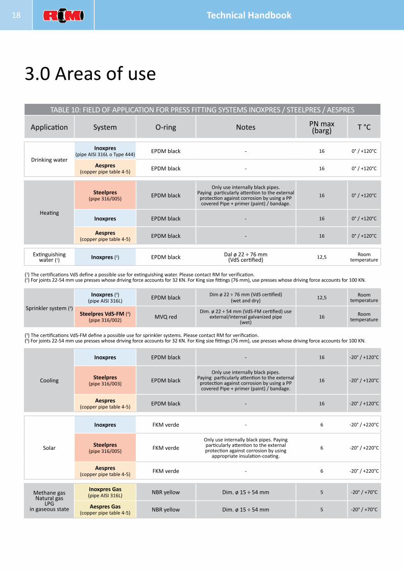
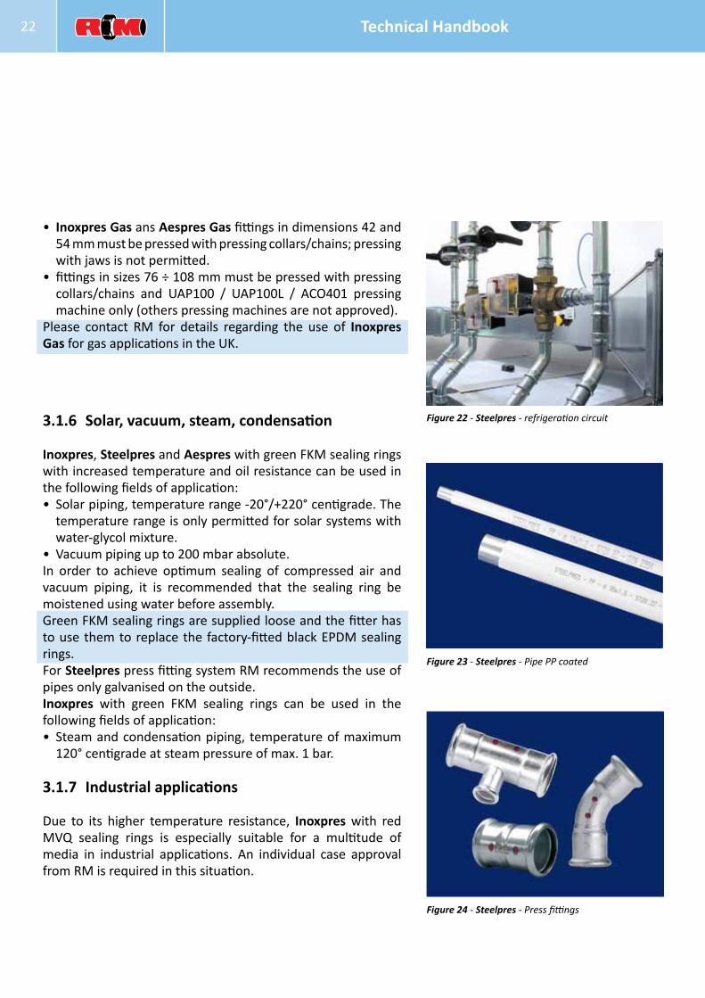
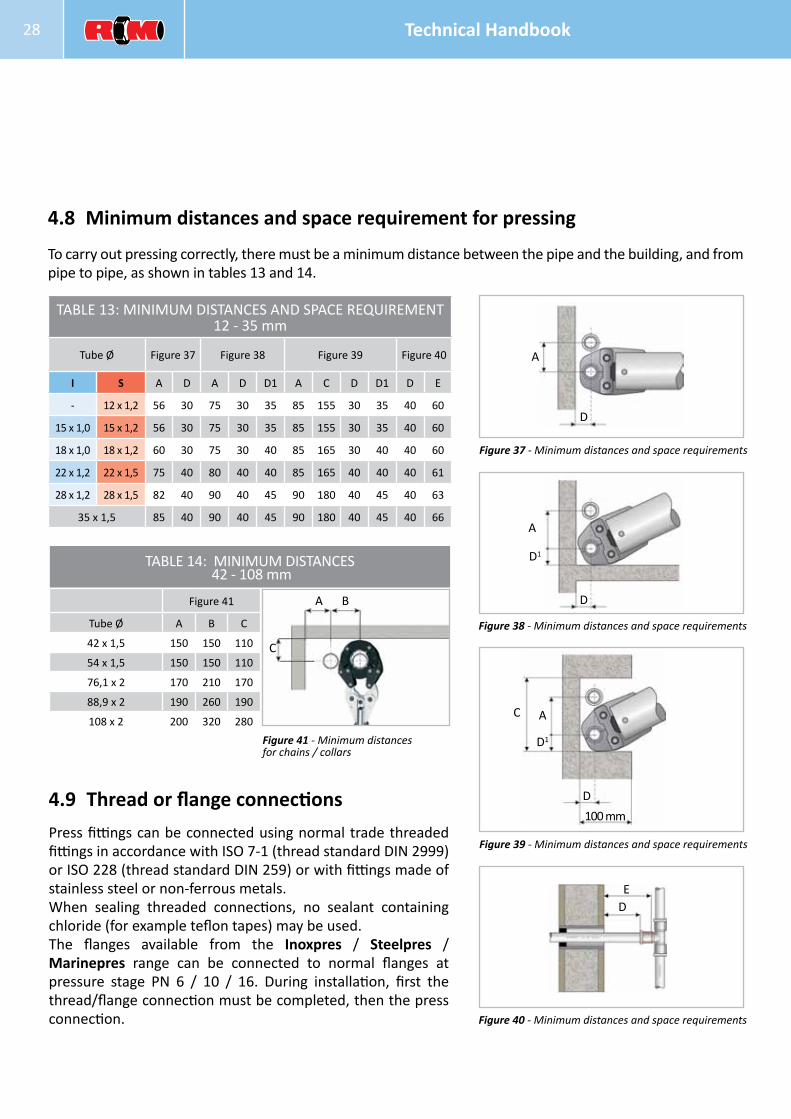
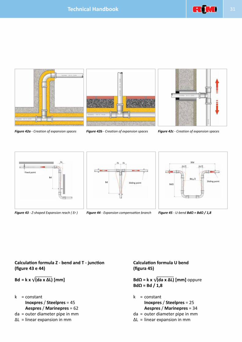
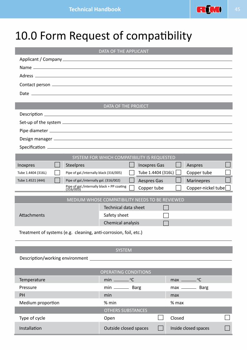
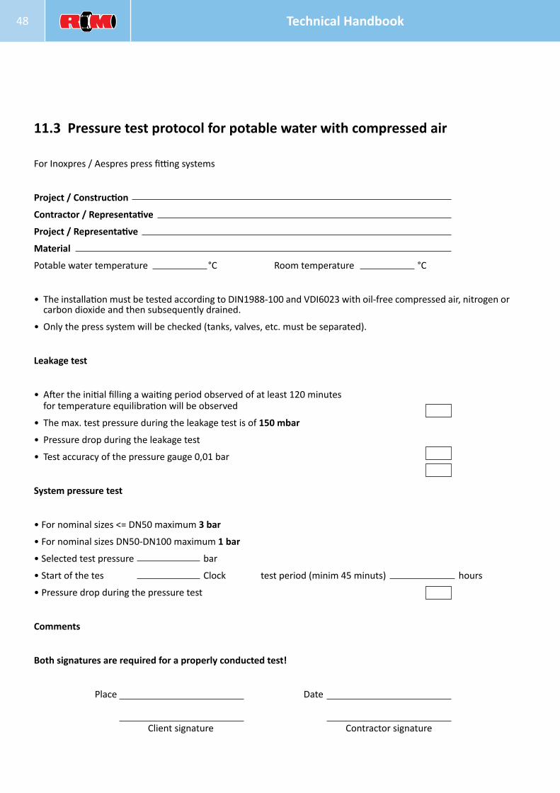

Code 012 R5 0115 GBR
raccorderiemetallichecom