presents general power quality - home - p3
TRANSCRIPT

www.p3-inc.com
2020
Building Confidence in Power
Presents
General Power Quality

www.p3-inc.com
2020
Building Confidence in Power

www.p3-inc.com
2020
Building Confidence in Power

www.p3-inc.com
2020
Building Confidence in Power
www.p3-inc.com
2020
Building Confidence in Power

www.p3-inc.com
2020
Building Confidence in Power

www.p3-inc.com
2020
Building Confidence in Power
• CEU’s
• Copy of Slides
• Evaluation Form
• Follow up Information
General Power Quality

www.p3-inc.com
2020
Building Confidence in Power
GOOD
POWER
BAD
POWER
Power Quality

www.p3-inc.com
2020
Building Confidence in Power
• What is good Power?
• What is Bad Power?
Power Quality
www.p3-inc.com
2020
Building Confidence in Power
NFPA 70 (NEC)

www.p3-inc.com
2020
Building Confidence in Power
IEEE Std 1100-2005
Power Quality

www.p3-inc.com
2020
Building Confidence in Power
What is good Power?
• IEEE is the most often quoted “Source” for
definitions of Power
• IEEE stands for “Institute of Electrical and
Electronic Engineers”
• IEEE defines Good Power as:
Clean, pure power exhibits constant voltage
and frequency, perfect sinusoidal waveshapes,
and is free of harmonics, noise, and transients.
Power Quality

www.p3-inc.com
2020
Building Confidence in Power
What is Bad Power?
IEEE defines Bad Power as:
Power that includes voltage variations, voltage swells,
voltage sags, over-voltages and under-voltages, harmonics,
transients, traveling waves, and power failures.
Power Quality

www.p3-inc.com
2020
Building Confidence in Power
Over-voltages
Under-voltages
Sags
Swells
Harmonics
Noise
Transients
Grounding
The Power Quality BIG 8

www.p3-inc.com
2020
Building Confidence in Power
Sags IEEE-1100
Swells IEEE-1100
Over-voltages IEEE-1100
Under-voltages IEEE-1100
Harmonics IEEE-519 and IEEE-1100
Noise IEEE-1100
Transients IEEE-C62.41 and IEEE 1100
Grounding IEEE-142 and IEEE 1100
The Power Quality BIG 8

www.p3-inc.com
2020
Building Confidence in Power
IEEE-1100-2.2.67:
A… reduction in the ac voltage, at the power
frequency, for durations from a 0.5 cycle to 1 Min.
Voltage Sag

www.p3-inc.com
2020
Building Confidence in Power
Voltage Sag

www.p3-inc.com
2020
Building Confidence in Power
Voltage Swell
IEEE 1100-2.2.78:
An increase in… voltage or current at
the power frequency for durations from
0.5 cycle to 1.0 min.

www.p3-inc.com
2020
Building Confidence in Power
Voltage Swell

www.p3-inc.com
2020
Building Confidence in Power
Over-voltages
IEEE-1100-2.2.56:
Increase in the ac voltage, at the power frequency, for a
period of time greater than 1 min.

www.p3-inc.com
2020
Building Confidence in Power
Over-voltages
Over Voltage

www.p3-inc.com
2020
Building Confidence in Power
Under-voltages
IEEE 1100-2.2.56:
Decrease in the ac voltage, at the power frequency, for
a period of time greater than 1 min.

www.p3-inc.com
2020
Building Confidence in Power
Voltage
12200
12400
12600
12800
13000
13200
13400
13600
4:15
4:45
5:15
5:45
6:15
6:45
7:15
7:45
8:15
8:45
9:15
9:45
10:1
5
10:4
5
11:1
5
11:4
5
12:1
5
12:4
5
13:1
5
Voltage
Under-voltages

www.p3-inc.com
2020
Building Confidence in Power
Utility Standards
Utility standards are defined by the various
State Utility Boards. Most require the utility must
adhere to this standard:
1. Voltage limits as stated by IEEE/ANSI C84.1

www.p3-inc.com
2020
Building Confidence in Power
IEEE/ANSI C84.1
Standard Voltage Voltage Range A Voltage Range B
120 114-126 110-127
120/240 114/228-126/252 110/220-127/254
208Y/120 197Y/114-218Y/126 191Y/110-220Y/127
480Y/277 456Y/263-504Y/291 440Y/254-508Y/293
13200Y 12870Y-13860Y 12504Y-13970Y
“Electrical supply systems shall be so designed and operated
that most service voltages will be within the limits for range A”
“When…Range B… voltages occur, corrective measures shall
be undertaken within a reasonable time to improve voltages to
meet Range A requirements.”
Utility Standards

www.p3-inc.com
2020
Building Confidence in Power
IEEE-1100-2.2.83:
A sub-cycle disturbance in the ac waveform that is
evidenced by a sharp, brief discontinuity of the
waveform. May be of either polarity and may be additive
to, or subtractive from, the nominal waveform.
Transient

www.p3-inc.com
2020
Building Confidence in Power
Transient
Actual P3
Power Quality
Study

www.p3-inc.com
2020
Building Confidence in Power
A
M
P
E
R
E
S
8x20 µs Short Circuit Current
TIME
3,000
10%
50%
20 µs
8 µs 0
90%
Impulse / Combination wave Transient
Transient

www.p3-inc.com
2020
Building Confidence in Power
Transient 8x20 µs Impulse
Location
Category
System
Exposure
Voltage
(kV)
Effective
Impedance
B1
B2
B3
C1
C2
C3
Low
Medium
High
Low
Medium
High
2
4
6
6
10
20
2
2
2
2
2
2
Current
(kA)
1
2
3
3
5
10
Peak Values
Voltage Current
A 6kV 500A
B 6kV 3000A
Combination Wave
Peak ValuesLocation Category
Voltage Current
C low 6kV 3kA
C high 10kV 10kA
Combination Wave
Peak ValuesLocation Category

www.p3-inc.com
2020
Building Confidence in Power
Transient
peak
r
Voltage Waveform B3 — 0.5 µs, 100 kHz Ring Wave
V peak
T = 10 µs (f = 100 kHz)
60% of V
0.9 V peak
0.1 V peak
0.5 µs
t
Ring Wave Transient

www.p3-inc.com
2020
Building Confidence in Power
Transient
Standard 0.5 µs - 100 kHz Ring Wave
Location
Category
System
Exposure
Voltage
(kV)
Effective
Impedance
A1
A2
A3
B1
B2
B3
Low
Medium
High
Low
Medium
High
2
4
6
2
4
6
30
30
30
12
12
12
Current
(kA)
.07
.13
.2
.17
.33
.5
Peak Values
Voltage Current
A 6kV 200A
B 6kV 500A
100kHz Ring Wave
Peak ValuesLocation Category

www.p3-inc.com
2020
Building Confidence in Power
IEEE 1100-2.2.49:
Unwanted electrical signals that produce
undesirable effects in the circuits of the
control- systems in which they occur.
Noise

www.p3-inc.com
2020
Building Confidence in Power
Noise
Noise, Waveform Capture

www.p3-inc.com
2020
Building Confidence in Power
Harmonics
A harmonic is the term
used for current flow on
your facilities power
system at frequencies
other than 60Hertz.

www.p3-inc.com
2020
Building Confidence in Power
Harmonics
Low Harmonic Waveform

www.p3-inc.com
2020
Building Confidence in Power
High Harmonic Waveform
Harmonics
www.p3-inc.com
2020
Building Confidence in Power
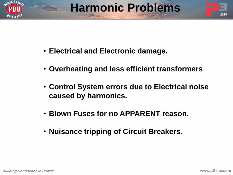
Harmonic Problems
• Electrical and Electronic damage.
• Overheating and less efficient transformers
• Control System errors due to Electrical noise
caused by harmonics.
• Blown Fuses for no APPARENT reason.
• Nuisance tripping of Circuit Breakers.

www.p3-inc.com
2020
Building Confidence in Power
Typical Harmonic frequencies
that cause problems:
Harmonic Frequencies
3 x 60 = 180HZ
5 x 60 = 300HZ
7 x 60 = 420HZ
11 x 60 = 660HZ
13 x 60 = 780HZ

www.p3-inc.com
2020
Building Confidence in Power
NEC 250.53 states that ground
resistance should be less than 25 ohms.
Is this true?
Grounding for Power Quality

www.p3-inc.com
2020
Building Confidence in Power
No! NEC 250.53 states “A single electrode
shall be supplemented by an
additional electrode…
If a single electrode has a resistance
to earth of 25 ohms or less the
supplemental electrode shall not be
required”.
Is this good enough?
Grounding for Power Quality

www.p3-inc.com
2020
Building Confidence in Power
Why Grounding for “Power Quality”?
IEEE 142
IEEE 142-5.1
The grounding of sensitive electronic equipment, such as computers,
programmable logic controllers, process plants, distributed control
systems, and similar electronic equipment, has been found to be one
of the important items in achieving useful operation from these
systems.
The low operating voltage of computers and other sensitive
electronic equipment makes them susceptible to random voltages far
below levels that are perceptible to humans and that have no effect
on electrical power equipment.
Certainly the voltages injected into the earth by lightning strokes
even within several thousand feet, unless suitable neutralization is
accomplished, can cause malfunction and can possibly damage the
equipment.

www.p3-inc.com
2020
Building Confidence in Power
IEEE 142-4.1.2 Recommended Acceptable Values
• The most elaborate grounding system may not perform
satisfactorily unless the connection of the system to earth is
adequate for the particular installation.
• With reference to power quality, the earth connection is one of the
most important parts of the whole grounding system.
• The connection to earth of the electrode system…
should be… 1-5 ohms for commercial and
industrial services.
Earth Reference

www.p3-inc.com
2020
Building Confidence in Power
IEEE 142-4.4.1 Need for Measurement
Many indeterminate factors exists in any formula for the calculation of the resistance to earth.
Total reliance should not be placed on the calculated results. For example, the soil resistivity
varies inversely with the soil temperature and directly with the moisture content and may vary with
the depth. The only certain way to determine the resistance is to measure it after the system has
been completed.
IEEE 142-4.4.3 Periodic Testing
Tests should be made periodically after the original installation and test so that it can be
determined whether the resistance is remaining constant or is increasing. If later tests show that
the resistance is increasing to an undesirable value, steps should be taken to reduce the
resistance…
Earth Reference After Installation
Don’t bury it and forget it!

www.p3-inc.com
2020
Building Confidence in Power
Power Quality Events
• Under-voltage
• Transient
• Swell
• Sag
• Harmonics
2
1
3
4
5
Know the problem BEFORE installing Power Quality Equipment

www.p3-inc.com
2020
Building Confidence in Power
Grounding and
Surge Protection Devices
Harmonic Mitigation
Power Conditioning
Uninterruptible
Power Supply System
Custom
Solution
The Power Quality Pyramid

www.p3-inc.com
2020
Building Confidence in Power
Power Factor

www.p3-inc.com
2020
Building Confidence in Power
• What is Power Factor?
• What is a good Power Factor?
• What is a Bad Power Factor?
• What problems are caused by a bad
Power Factor?
• How to correct for a bad Power Factor.
Power Factor

www.p3-inc.com
2020
Building Confidence in Power
What is Power Factor?
• Power Factor is the ratio of Active Power to Total Power
Active Power
Total Power = Power Factor

www.p3-inc.com
2020
Building Confidence in Power
Active Power
• Active power is what we normally see as the electricity used in our
facility.
• Measured in kW (Kilowatts).
• This is normally what the power company charges against.
Main
Service
Motor
Control
Center
Sub-
Power
Panels
Sub-
Power
Panels
Lights
Phones
Computers Etc.
Motor Motor Motor
kWh
METER

www.p3-inc.com
2020
Building Confidence in Power
Total Power
• Total power is what our equipment needs to be sized for in our facility.
• Measured in KVA (Kilo-voltamps).
• The power company may charge extra money (penalties) for a large KVA.
• The large KVA is usually stated in Power Factor.
Total Power is a combination of Active Power
and something called Reactive Power.
Active Power
Total Power = Power Factor

www.p3-inc.com
2020
Building Confidence in Power
Measured in Kvar
• Reactive Power takes into consideration the energy
needed to build all the magnetic fields in a facility.
• Your facilities equipment must be sized large enough to
handle the extra energy needed to produce these
magnetic fields.
• Magnetic fields are produced in ALL current carrying
equipment in a facility. This includes Switchboards,
Panelboards, Busway, wiring, all equipment, and
especially MOTORS and TRANSFORMERS. Motors and
Transformers have thousands of feet of wire, which add
greatly to a facilities Reactive Power
Reactive Power

www.p3-inc.com
2020
Building Confidence in Power
Magnetic Fields
• In a AC (Alternating Current) system, current flow
changes direction 60 times every second. This is called
60 Hertz (Hz).
• Each time the current changes direction a magnetic
field is developed around ALL current carrying parts of a
circuit.
• This includes all the wire in your facility, all motors and
all transformers.
Produced in your Facility

www.p3-inc.com
2020
Building Confidence in Power
0V
680V
680V Section of Wire
Produced around Wire
Magnetic Fields

www.p3-inc.com
2020
Building Confidence in Power
0V
680V
680V Section of Wire
Produced around Wire
Magnetic Fields

www.p3-inc.com
2020
Building Confidence in Power
Reactive Power
• The energy needed to produce this Magnetic Field is real.
• You don’t see it on your energy bill because the power is
given back to the circuit in each quarter cycle.
• The extra current flow is there. Therefore, you and your
power company must size equipment large enough to
handle the extra energy needed to produce these magnetic
fields.
• This is why many Power Companies add an extra charge
(penalty) to facilities with a large amount of reactive power.

www.p3-inc.com
2020
Building Confidence in Power
Remember…
Total Power is a combination of
Active Power and Reactive Power.
This is how they combine:
Active Power (kW)
Reactive Power (kvar)
Total Power (kva)
Active Power (kW)2 + Reactive Power (kvar)2 = Total Power (kva)2
Power Factor

www.p3-inc.com
2020
Building Confidence in Power
As Reactive Power increases Active Power
stays the same however Total Power increases
greatly.
Active Power (kW)
Larger
Reactive Power
(kvar)
Larger
Total Power (kVA)
Power Factor

www.p3-inc.com
2020
Building Confidence in Power
Remember
• Power Factor is the ratio of Active Power to Total
Power .
• When Reactive Power is large Total Power
increases.
• With the formula below we now see that when Total
Power increases the Power Factor decreases.
Active Power
Total Power = Power Factor

www.p3-inc.com
2020
Building Confidence in Power
• When Total Power increases the Power Factor decreases.
Active Power
Total Power = Power Factor
1000 kW
1050 kVA .95 Power Factor
= 1000 kW
1500 kVA .6 Power Factor
Power Factor

www.p3-inc.com
2020
Building Confidence in Power
= 1000 kW
1050 kVA .95 Power Factor
= 1000 kW
1500 kVA .6 Power Factor
• .95 to 1 is considered a good power factor.
• Anything less than .9 can be considered a bad Power Factor.
• Your Power Company may charge you or you may have
internal problems in your facility with Power Factors less
than .9.
Power Factor

www.p3-inc.com
2020
Building Confidence in Power
• The best way solve a low Power Factor problem is
to install Power Factor Correction Capacitors.
• These Power Factor Correction Capacitors capture
the energy from the collapsing magnetic field and
give the energy back on the next Quarter cycle.
Power Factor

www.p3-inc.com
2020
Building Confidence in Power
Power Factor Capacitor Storage of
Magnetic Fields Produced in your Facility
Power
Factor
Correction
Capacitor
0V
680V
680V Section of Wire
Power Factor

www.p3-inc.com
2020
Building Confidence in Power
= 1000 kW
1500 kVA .6 Power Factor
Gaining Capacity
If we increase Power Factor, what happens to KVA?
= 1000 kW
1050 kVA .95 Power Factor
with Power Factor Capacitors

www.p3-inc.com
2020
Building Confidence in Power
1500 kVA on a 480 3 phase system is 1800 AMPS
1050 kVA on a 480 3 phase system is 1200 AMPS
Could we use this gain of 600 amps?
Absolutely!
Gaining Capacity
with Power Factor Capacitors

www.p3-inc.com
2020
Building Confidence in Power
Harmonics

www.p3-inc.com
2020
Building Confidence in Power
What is a Harmonic?
A harmonic is the term used
for current flow on your facilities
power system at frequencies
other than 60Hertz.

www.p3-inc.com
2020
Building Confidence in Power
What exactly is
a Harmonic?

www.p3-inc.com
2020
Building Confidence in Power
Linear Use of Power
Volts
Amps
0V
680V
680V
0A
200A
200A

www.p3-inc.com
2020
Building Confidence in Power
Equipment that uses power in a
Linear Fashion
Linear Use of Power

www.p3-inc.com
2020
Building Confidence in Power
Non-Linear Use of Power
Volts
Amps
0V
680V
680V
0A
200A
200A

www.p3-inc.com
2020
Building Confidence in Power
Equipment that uses power in a
NON-linear fashion
Computers Fluorescent Lights
and Ballast's Copiers and other
Office equipment
Variable Frequency
Drives
All equipment that uses
an AC to DC power supply
Non-Linear Use of Power

www.p3-inc.com
2020
Building Confidence in Power
3 x 60 = 180HZ
5 x 60 = 300HZ
7 x 60 = 420HZ
11 x 60 = 660HZ
13 x 60 = 780HZ
Typical Non-Linear frequencies
that cause problems:
Harmonic Problems

www.p3-inc.com
2020
Building Confidence in Power
Why does Non-Linear
current flow cause problems
In my facility?
Harmonic Problems

www.p3-inc.com
2020
Building Confidence in Power
0V
680V
680V Section of Wire
Magnetic Fields
Produced around Wire

www.p3-inc.com
2020
Building Confidence in Power
Combination
of Linear & Non-Linear Power
0A
200A
200A Section of Wire

www.p3-inc.com
2020
Building Confidence in Power
Harmonic Problems
• Electrical and Electronic damage.
• Overheating and less efficient transformers
• Control System errors due to Electrical noise
caused by harmonics.
• Blown Fuses for no APPARENT reason.
• Nuisance tripping of Circuit Breakers.

www.p3-inc.com
2020
Building Confidence in Power
IEEE 519- Current
Maximum Harmonic Current Distortion
ISC / IL TDD
1-20 5%
20-50 8%
50-100 12%
100-1000 15%
1000+ 20%
ISC=Maximum short circuit current
IL= Maximum demand load
TDD= Total Demand Distortion
Harmonic Problems

www.p3-inc.com
2020
Building Confidence in Power
Example:
Typical Office Building
1200A 208Y/120 service
30K AIC
The Maximum IEEE Harmonic distortion is:
30,000 AIC / 960 = 31
31 on the IEEE chart is 8%
Current Harmonics

www.p3-inc.com
2020
Building Confidence in Power
IEEE 519 -Voltage
Maximum Harmonic Voltage Distortion
Voltage THD
69kV and below 5%
THD=Total Harmonic Distortion
Harmonic Problems

www.p3-inc.com
2020
Building Confidence in Power
Passive
Filter
Xs
M
XT
M
Line
Reactors
G
UPS
w/Filter
Oversized
Generator
HMT
HCU
SM
Modern Harmonic Solutions
IGBT
VFD’s
SCR
VFD
www.p3-inc.com
2020
Building Confidence in Power
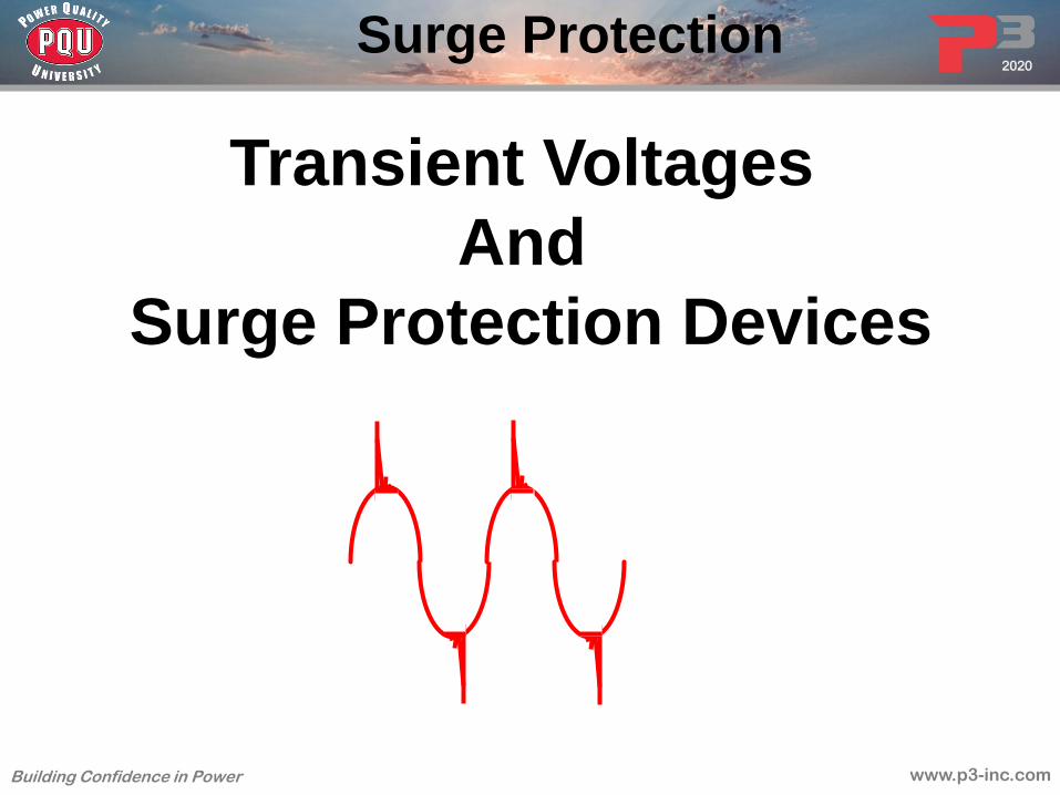
Transient Voltages
And
Surge Protection Devices
Surge Protection

www.p3-inc.com
2020
Building Confidence in Power
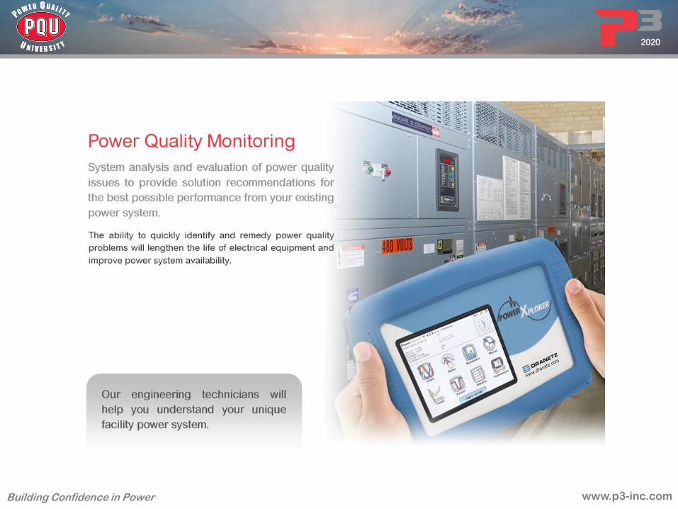
• Surge Protection Devices are used to help stop
Voltage Spikes and Surges from destroying
your facilities Electrical and Electronic
Equipment and Data.
Surge Protection

www.p3-inc.com
2020
Building Confidence in Power
Voltage Spikes and Surges are known as
Voltage Transients, or just Transients.
+170V
Normal 120 Volt 60Hz
AC Voltage Sine Wave
-170V
0V
+170V
120 Volt 60Hz AC Voltage
Sine Wave With Transients
-170V
0V
Surge Protection

www.p3-inc.com
2020
Building Confidence in Power
SPD Lightning/Surge
Arrestor
UL 1449.
Addressed by ANSI/IEEE 1100
No performance standard
addressed by UL nor ANSI/IEEE
SPD Lightning
Surge
Arrestor
No standard for limiting
Voltages
Proper Design will limit
voltages to ANSI/IEEE
3.4.3 Levels
Surge Protection

www.p3-inc.com
2020
Building Confidence in Power
What causes these Transients?
Motors Fluorescent Lights
& Ballasts
Copiers & other office equipment
Welders & other industrial equipment
Motors

www.p3-inc.com
2020
Building Confidence in Power
Internal in your Facility:
Motors
Ballasts
Office Equipment
Industrial Equipment
External to your Facility:
Lightning
Power Grid Problems
80%
20%
Transients come from two sources
Surge Protection

www.p3-inc.com
2020
Building Confidence in Power
Transients
Generated by Switching 2x4,
4 bulb fixture

www.p3-inc.com
2020
Building Confidence in Power
Generated by Capacitor Switching
IEEE Example Transients

www.p3-inc.com
2020
Building Confidence in Power
Generated by Energizing a Transformer
IEEE Example Transients

www.p3-inc.com
2020
Building Confidence in Power
Transient caused by
Actual P3
Power Quality
Study
Switching a 120 volt 1500 Watt
plug in Heater

www.p3-inc.com
2020
Building Confidence in Power
Caused by Harmonics
IEEE Example Transients

www.p3-inc.com
2020
Building Confidence in Power
Caused by Motor Switching
IEEE Example Transients

www.p3-inc.com
2020
Building Confidence in Power
Transients
Time
-7500
-5000
-2500
0
2500
5000
7500
14 12 10 0
Oscillatory Transient
(Ring Wave)
80 60 40 20 0 -1.5
-1.0
-.05
.00
.05
1.0
1.5
2.0
100 Time
Impulse Transient

www.p3-inc.com
2020
Building Confidence in Power
Some Problems caused by Transients
in your Facility:
• Premature Equipment failure
• Long term cumulative equipment damage
• Power loss
• Data losses and system resets
• Catastrophic equipment failure
• Immediate operation shutdown
• Expensive equipment repair and replacement costs
Transients

www.p3-inc.com
2020
Building Confidence in Power
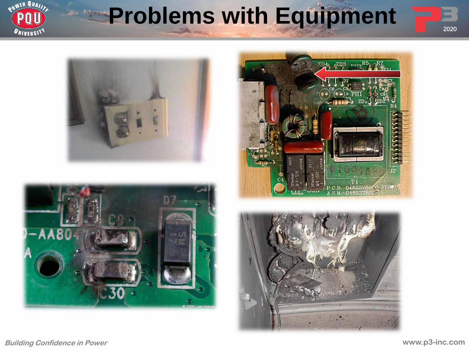
Problems with Equipment
• Motor
Windings
• Premature or
complete
motor failure

www.p3-inc.com
2020
Building Confidence in Power
Contact Failure from lightning strike
Problems with Equipment
www.p3-inc.com
2020
Building Confidence in Power
Problems with Equipment

www.p3-inc.com
2020
Building Confidence in Power
Problems with Equipment
L
E
D
Lighting
ight
mitting
iode

www.p3-inc.com
2020
Building Confidence in Power
What’s a Diode?
• The diode is an electronic semiconductor
(PN junction)
• It is the basis of design for Transistors
• Highly susceptible to Transients
• Must be protected by a SPD

www.p3-inc.com
2020
Building Confidence in Power
Problems with Equipment

www.p3-inc.com
2020
Building Confidence in Power
Surge Protection

www.p3-inc.com
2020
Building Confidence in Power
Electron Microscopic Photo
Catastrophic
Cross cut view
Cumulative Top view
From AD Inc.

www.p3-inc.com
2020
Building Confidence in Power
The Protection Circuit
SPD
Switchgear
Motor Control
Centers
Lights
Phones
Computers
Etc.
480V
Incoming
Power
Neutral
Ground
6000V
Voltage
Spike
800V Maximum
Clamp by SPD

www.p3-inc.com
2020
Building Confidence in Power
The SPD unit is designed to:
• Protect equipment from damage
Therefore, the SPD unit must:
• Sense transients quickly- <1 nanosecond
• Limit the let- through voltage- IEEE 3.4.3
• Inform user if not functioning- Alarms
• Not interrupt Normal Service- while doing its job
Surge Protection

www.p3-inc.com
2020
Building Confidence in Power
How do SPD’s work?
The Hybrid Circuit
SPD
MOV,Diode,
Capacitor,
Inductor,Fuse
Switchgear
Motor Control
Centers
Lights
Phones
Computers
Etc.
480V
Incoming
Power
Neutral
Ground
6000V
Voltage
Spike
800V Maximum
Clamp by SPD

www.p3-inc.com
2020
Building Confidence in Power
NEC Code and SPD
NFPA 70 NEC REQUIREMENTS for SPD’s
695.15 Fire Pump Controllers
700.8 Emergency Systems
708.20 Critical Operations
670.6 Safety Interlocks
620.51(E) Emergency Systems Loads
645.18 Data Centers
694.7(D) Wind Electric Systems
230.67 <-New for 2020 Dwelling Units

www.p3-inc.com
2020
Building Confidence in Power
NEC Code and SPD
700.8 Surge Protection. A listed SPD shall be installed in or
on all emergency systems switchboards and panelboards.
700.2 Emergency Systems are: Those systems legally required and
classed as emergency by municipal, state, federal, or other codes, or by any governmental
agency having jurisdiction. These systems are intended to automatically supply
illumination, power, or both,… illumination is required for safe exiting… such as hotels,
theaters, sports arenas, health care facilities, and similar institutions… ventilation, fire
detection and alarm systems, elevators, fire pumps, public safety communications systems,
industrial processes where current interruption would produce serious life safety or health
hazards, and similar functions.

www.p3-inc.com
2020
Building Confidence in Power
620.51 (E) Surge Protection. Where any of the disconnecting
means
in 620.51 has been designated as supplying an emergency
system load, surge protection shall be provided.
620.51 Loads are: 1. Elevators Without Generator Field Control. 2.Elevators with Generator
Field Control. 3.Escalators and Moving Walks. 4.Platform Lifts and Stairway Chairlifts.
NEC Code and SPD

www.p3-inc.com
2020
Building Confidence in Power
Note: it says “shall have”, not “should have” surge protection installed.
"Industrial machinery with safety interlock circuits shall have surge protection installed". The concern is failure of safety interlocks on machinery poising safety risk to operators that may not be aware of disabled safety mechanisms.
670.6 Surge Protection. Industrial machinery with safety
interlock circuits shall have surge protection installed.
NEC Code and SPD

www.p3-inc.com
2020
Building Confidence in Power
NEC Code and SPD
695.15 Surge Protection. A listed surge protection device
shall be installed in or on the fire pump controller.

www.p3-inc.com
2020
Building Confidence in Power
NEC Code and SPD
708.20 Surge Protection Devices. Surge protection devices shall
be provided at all facility distribution voltage levels… in Critical
Operations Power Systems (COPS)
708.2 Critical Operations Power Systems (COPS). Power systems for
facilities or parts of facilities that require continuous operation
for the reasons of public safety, emergency management,
national security, or business continuity.

www.p3-inc.com
2020
Building Confidence in Power
NEC Code and SPD
645.18 Surge Protection for Critical Operations Data Systems.
Surge protection shall be provided for critical operations data
Systems.
645.2 Critical Operations Data System. An information technology
equipment system that requires continuous operation for reasons of
public safety, emergency management, national security, or business continuity.

www.p3-inc.com
2020
Building Confidence in Power
NEC Code and SPD
694.7(D) Surge Protective Devices (SPD). A surge protective
device
shall be installed between a wind electric system and any loads
served by the premises electrical system.

www.p3-inc.com
2020
Building Confidence in Power
NEC Code and SPD
230.67 Surge Protective Devices (SPD). A. All Services supplying a dwelling unit must have a surge protection device
B. The SPD must be part of the service equipment or immediately adjacent to it.
C. The SPD must be a Type 1 or Type 2 device
D. An SPD must be provided when service equipment is replaced

www.p3-inc.com
2020
Building Confidence in Power
The latest
UL 1449
Specification
Surge Protection

www.p3-inc.com
2020
Building Confidence in Power
700 700 700
• SPD Type
• NRTL listing mark
• Peak surge current per phase
(not required)
• Short circuit current rating
• Nominal Discharge Current
Rating
• System voltages
• System frequency
• Voltage Protection Rating
The New UL1449 Specification
XYZ-400-208Y

www.p3-inc.com
2020
Building Confidence in Power
700 700 700
• SPD Type
• NRTL listing mark
• Peak surge current per phase
(not required)
• Short circuit current rating
• Nominal Discharge Current
Rating
• System voltages
• System frequency
• Voltage Protection Rating
XYZ-400-208Y
The New UL1449 Specification

www.p3-inc.com
2020
Building Confidence in Power
UL 1449 – SPD Type
The SPD type refers to the location where the
SPD can be used:
Type 1: before the service disconnect overcurrent
device
Type 2: after service disconnect overcurrent device
Type 3: at least 10m (30 ft) of conductor between
service disconnect overcurrent device and
SPD
Type 4: component SPD (must be tested to the
appropriate installation location where it will
be installed)

www.p3-inc.com
2020
Building Confidence in Power
Locations for SPD Types
Type 1
Before service disconnect
Type 2 (Type 1 permitted)
After service disconnect
Type 2 or Type 3 (Type 1 permitted)
30 feet of conductor between service disconnect and SPD
Type 3,4,5 Component Level

www.p3-inc.com
2020
Building Confidence in Power From ANSI/IEEE 1100
Conventional Industry Standard
Figure 8-25 – Typical locations of power distribution surge protective devices
8.6.4 Premise electrical system surge protection
In addition to surge protective devices installed in the service entrance equipment, it is
recommended that additional surge protective devices… be applied to downstream electrical
switchboards and panelboards, and panelboards on the secondary of separately derived
systems if they support communications, information technology equipment, signaling,
television, or other form of electronic load equipment (see Figure 8-25).
At the Main At the Sub Panel At the Load

www.p3-inc.com
2020
Building Confidence in Power
700 700 700
• SPD Type
• NRTL listing mark
• Peak surge current per phase
(not required)
• Short circuit current rating
• Nominal Discharge Current
Rating
• System voltages
• System frequency
• Voltage Protection Rating
XYZ-400-208Y
The New UL1449 Specification

www.p3-inc.com
2020
Building Confidence in Power
Nationally Recognized Testing
• Other laboratories besides
Underwriters Laboratories can test
and list devices to be compliant with
any standard, including UL 1449
• An SPD tested by another NRTL can
be “Compliant to UL 1449” but will be
“Listed” by the NRTL – e.g. “ETL
Listed”, “CSA Listed”
Laboratory Mark - NRTL

www.p3-inc.com
2020
Building Confidence in Power
700 700 700
• SPD Type
• NRTL listing mark
• Peak surge current per
phase (not required)
• Short circuit current rating
• Nominal Discharge Current
Rating
• System voltages
• System frequency
• Voltage Protection Rating
XYZ-400-208Y
The New UL1449 Specification

www.p3-inc.com
2020
Building Confidence in Power
What “Peak Surge” do you need?
Use Industry Standards
Application Size Chart

www.p3-inc.com
2020
Building Confidence in Power
700 700 700
• SPD Type
• NRTL listing mark
• Peak surge current per phase
(not required)
• Short circuit current rating
• Nominal Discharge Current
Rating
• System voltages
• System frequency
• Voltage Protection Rating
XYZ-400-208Y
The New UL1449 Specification
• Measure of how much current the electrical
utility can supply during a fault condition

www.p3-inc.com
2020
Building Confidence in Power
700 700 700
• SPD Type
• NRTL listing mark
• Peak surge current per phase
(not required)
• Short circuit current rating
• Nominal Discharge Current
Rating
• System voltages
• System frequency
• Voltage Protection Rating
XYZ-400-208Y
The New UL1449 Specification
www.p3-inc.com
2020
Building Confidence in Power
• Manufacturer chooses a current they want to test with:
Type 1: 10kA or 20kA
Type 2: 3kA, 5kA, 10kA or 20kA
• Complete SPD is tested along with any required
overcurrent devices (fuse or breaker)
• Measured let through voltage for a 6000V 3000A surge
is recorded
• SPD is subjected to 15 surges at chosen current one
minute apart with rated voltage applied between surges
• Measured let through voltage for a 6000V and 3000A
surge is recorded again – let through voltage must
not deviate more than 10% from original voltage
(this is brand new!)
Nominal Discharge Current - In

www.p3-inc.com
2020
Building Confidence in Power
700 700 700
• SPD Type
• NRTL listing mark
• Peak surge current per phase
(not required)
• Short circuit current rating
• Nominal Discharge Current
Rating
• System voltages
• System frequency
• Voltage Protection Rating
XYZ-400-208Y
The New UL1449 Specification

www.p3-inc.com
2020
Building Confidence in Power
700 700 700
• SPD Type
• NRTL listing mark
• Peak surge current per phase
(not required)
• Short circuit current rating
• Nominal Discharge Current
Rating
• System voltages
• System frequency
• Voltage Protection Rating
XYZ-400-208Y
The New UL1449 4th Edition Specification

www.p3-inc.com
2020
Building Confidence in Power
• Voltage Protection Rating
is assigned to an
SPD model by the NRTL
from a table based on the
average of the measured
limiting voltage from
3 impulses of a
6000V/3000A Transient
Voltage Protection Rating “VPR”

www.p3-inc.com
2020
Building Confidence in Power
UPS Systems

www.p3-inc.com
2020
Building Confidence in Power
An Uninterruptible Power Supply system
is a device that provides
power to your facilities equipment
when the normal power provider cannot.
UPS Systems

www.p3-inc.com
2020
Building Confidence in Power
Purpose of a UPS
• Originally to provide back-up power during power fail
conditions
• Expanded application to cover line and load power quality
issues
Dirty, AC Input Clean, continuous output
during abnormal line/load
conditions
Uninterruptible
Power Supply

www.p3-inc.com
2020
Building Confidence in Power
IEEE 1100
Section 7 tells us:
The correct UPS System can solve
7 of the 8 power problems that cause failure
or malfunction
of equipment in your facilities.
UPS Systems

www.p3-inc.com
2020
Building Confidence in Power
Over-voltage
Under-voltage
Sag
Swell
Transient
Noise
Long term
outage
Frequency
variation
N
N
N
N
Y
?
N
N
N
N
N
N
N
Y
N
N
N
N
N
N
?
?
N
N
N
N
Y
Y
?
Y
N
N
?
?
N
N
N
N
Y
?
N
N
N
N
N
N
?
N
Y
Y
N
N
N
N
?
?
Y
Y
Y
Y
Y
Y
?
Y

www.p3-inc.com
2020
Building Confidence in Power
There are three basic types of
Uninterruptible Power Supply
systems available:
1. Stand by (Off line)
2. Line interactive (Off Line)
3. True On line Double Conversion
UPS Systems

www.p3-inc.com
2020
Building Confidence in Power
Equipment that
needs
uninterruptible
power Power from
normal
power
provider
Batteries and DC to
AC Inverter
Stand By UPS System
The stand by UPS system (sometimes called Off-line system) operates
in the following manor:
While the normal power provider is operational the equipment wired to the UPS
system receives power from this normal power provider. When this normal power is
lost (blackout) the UPS system activates (turns on) and supplies power to the
equipment that needs uninterruptible power until the normal power returns. The way
this UPS system creates power is by converting the DC power from batteries to AC
via an inverter. The activation (turn on) time for the inverter and internal switch from
normal power to inverter power is typically 8-16 milliseconds.

www.p3-inc.com
2020
Building Confidence in Power
Equipment that
needs
uninterruptible
power Power from
normal
power
provider
Batteries and DC to
AC Inverter
Stand By UPS System The stand by UPS system (sometimes called Off-line system) operates
in the following manor:
While the normal power provider is operational the equipment wired to the UPS
system receives power from this normal power provider. When this normal power is
lost (blackout) the UPS system activates (turns on) and supplies power to the
equipment that needs uninterruptible power until the normal power returns. The way
this UPS system creates power is by converting the DC power from batteries to AC
via an inverter. The activation (turn on) time for the inverter and internal switch from
normal power to inverter power is typically 8-16 milliseconds.

www.p3-inc.com
2020
Building Confidence in Power
Equipment that
needs
uninterruptible
power Power from
normal
power
provider
Batteries and DC to
AC Inverter
Stand By UPS System
The stand by UPS system (sometimes called Off-line system) operates
in the following manor:
While the normal power provider is operational the equipment
wired to the UPS system receives power from this normal power
provider. When this normal power is lost (blackout) the UPS system
activates (turns on) and supplies power to the equipment that needs
uninterruptible power until the normal power returns. The way this UPS
system creates power is by converting the DC power from batteries to AC
via an inverter. The activation (turn on) time for the inverter and internal
switch from normal power to inverter power is typically 8-16 milliseconds.

www.p3-inc.com
2020
Building Confidence in Power
Equipment that
needs
uninterruptible
power Power from
normal
power
provider
Batteries and DC to
AC Inverter
Stand By UPS System

www.p3-inc.com
2020
Building Confidence in Power
Equipment that
needs
uninterruptible
power Power from
normal
power
provider
Batteries and DC to
AC Inverter
Stand By UPS System

www.p3-inc.com
2020
Building Confidence in Power
Benefits:
• Inexpensive
• Small Footprint
Disadvantages:
• Not Designed for Critical Loads
• No Power Conditioning
• Load Exposed to Surges, Sags, and
transients
• Not Generator Compatible
• Switching Necessary to go from Utility
to battery Power. Discontinuous Power
during Switch to Battery
• Less Battery Life (Used more often)
• Poor Maintainability without
maintenance Bypass
Stand By (Off Line) UPS System

www.p3-inc.com
2020
Building Confidence in Power
Equipment that
needs
uninterruptible
power
Power from
normal
power
provider
Batteries and
DC to AC
Inverter
Voltage
Regulator
Typically
A Buck Boost
Transformer
Line Interactive UPS System
Line interactive (Off Line) UPS systems add extra features that give us, at
a minimum, two advantages over the Stand By UPS system. One, they
usually include some type of voltage regulator between the normal power
provider and your equipment that needs uninterruptible power and two,
they have activation times around 4-8 milliseconds.

www.p3-inc.com
2020
Building Confidence in Power
Benefits:
• Less Costly than
True on Line
Technology
• Some Power
conditioning
Disadvantages:
• Not Designed for Critical Loads
• Limited Power Conditioning
• Load Exposed to Surges, Sags,
and Transients
• Not always Generator compatible
• Less Battery Life (Used more often)
• Poor Maintainability without a
maintenance bypass
Line Interactive UPS System

www.p3-inc.com
2020
Building Confidence in Power
Power
from
normal
power
provider
Equipment that
needs
uninterruptible
power
AC to DC
Rectifier
Batteries
DC
DC to AC
Inverter
True On Line UPS system
Double Conversion The On Line UPS is the best option when your equipment cannot loose power for even a split second. With an
On Line system power is constant and there is no activation time. The On Line system uses batteries and a
DC to AC inverter just like to other two units mentioned above, however, it also uses something called a
rectifier. The addition of the rectifier along with the batteries and inverter enable the On Line UPS to give
constant power to your equipment that needs uninterruptible power. The inverter that supplies power to your
equipment is always on. The inverter gets its power from either the normal power provider (via the rectifier) or
the batteries. With power to your equipment being supplied constantly from the inverter you receive clean
regulated power at all times. In many cases this On Line technology is the only answer to your sensitive
equipment power needs.

www.p3-inc.com
2020
Building Confidence in Power
Power
from
normal
power
provider
Equipment that
needs
uninterruptible
power
AC to DC
Rectifier
Batteries
DC
DC to AC
Inverter
True On Line UPS system
Double Conversion

www.p3-inc.com
2020
Building Confidence in Power
Power
from
normal
power
provider
Equipment that
needs
uninterruptible
power
AC to DC
Rectifier
Batteries
DC
DC to AC
Inverter
True On Line UPS system
Double Conversion

www.p3-inc.com
2020
Building Confidence in Power
Benefits:
• Designed for Critical Loads
• Superior Power Conditioning
• Isolates Load from Surges, Sags,
and Transients
• Generator Compatible
• Extended Battery Times available
with Full Time inverter
• Extended Battery Life (Only used
during emergencies)
• Easy to Maintain with maintenance
Bypass Switch
Disadvantages:
• More Expensive than
lessor technologies
• Bigger Footprint
True On Line UPS system
Double Conversion

www.p3-inc.com
2020
Building Confidence in Power
The True On Line UPS is the best solution if
the Uninterrupted operation of your
equipment is critical.
True On Line UPS system
Double Conversion

www.p3-inc.com
2020
Building Confidence in Power

www.p3-inc.com
2020
Building Confidence in Power

www.p3-inc.com
2020
Building Confidence in Power
General Power Quality
Thank you for attending
END
Please fill out the evaluation form
to receive attendance credit.