presentazione standard di powerpoint - inaf · just one inclinometer has been fully tested on srt...
TRANSCRIPT

G. Serra [email protected]
on behalf of Metrology team*
*T. Pisanu, S. Poppi, F.Buffa, P. Marongiu, R. Concu, G. Vargiu, P. Bolli, A. Saba, M.Pili, E.Urru
Astronomical Observatory of Cagliari
Gothenburg, Sweden, September 1-2, 2014
RadioNet Technical Workshop “Metrologies at radio astronomy antennas”
Italian National Institute for Astrophysics Astronomical Observatory of Cagliari
Sardinia Radio Telescope
SRT status at the end of technical validation (scientific validation in progress)
SRT metrology short-term goals Work progress status of the first SRT metrology systems: ◦ With-phase microwave holography ◦ Inclinometers ◦ Optical laser and Position sensing devices (PSD) ◦ Temperature probes
Other systems and future plans
Conclusions
The Metrology systems for SRT
Agenda

The Metrology systems for SRT
SRT features
A quick summary of the SRT features:
fully steerable quasi-gregorian alt-azimuthal mounting reflector antenna
active surfaces (64m-dia primary mirror
and 8m-dia reflectors) made up of more than a thousand adjustable panels
Frequency range: 0.3-100 GHz
3 main focal positions able to host up to 20 receivers
September 30th 2013, SRT opening cerimony

The Metrology systems for SRT
SRT receivers
At the present SRT is able to observe the sky in the frequency range: 0.3-26 GHz
0.3-0.41 /1.3-1.8 GHz
P/L-
band
rece
iver
S-band and Q-band multifeed receivers founded and in developement. A 100 GHz receiver got from IRAM
18-26 GHz
K-ba
nd re
ceiv
er
Gregorian Focus
5.7-7.7 GHz
C-ba
nd re
ceiv
er
BWG foci

The Metrology systems for SRT
SRT surface accuracy
After the first panels alignment of the secondary (in 2010) and primary mirror (in 2012) with fotogrammetry measurement (by SIGMA 3D)
Overall RMS accuracy of the reflecting surfaces ε~ 310 μm (= λ/20 @ ~ 48 GHz)
Accuracy: ~ 60 μm RMS @ 45° elevation
Subreflector surface
Accuracy: ~ 290 μm RMS @ 45° elevation
Primary reflector surface
Very good surface efficiency up to 48 GHz

The Metrology systems for SRT
Antenna performances
After the fine tuning of the telescope with active surfaces working, the pointing model allows SRT to observe at 22 GHz with a:
focusing accuracy < 1 mm ( λ/10 @ 1 cm ~ 30 GHz) an azimuth and elevation pointing errors < 4 arc sec (HPBW/10 @ λ =1 cm ~ 30 GHz )
Note. Recent antenna optics calibration has improved the gain at lower elevation angles
gain at 23 GHz over the SRT elevation angular range
0.66 K/Jy expected
SRT gain at 23 GHz

The Metrology systems for SRT
Short-term goals
Waiting for the higher frequency receivers, the metrology team is working to further improve the current SRT efficiency
Short-term goals: ◦ primary surface accuracy better than 150 µm (i.e. an overall surface
accuracy 190 µm, a very good efficiency up to ~80 GHz ) with Microwave holography system to measure RT far-field pattern by pointing a Ku-band GEO satellite (elevation angle 44 deg )
◦ azimuth and elevation errors < HPBW/10 ( ~ 1 arcsec with HPBW =12
arcsec @ 100 GHz ) with two inclinometers on the alidade ◦ focusing accuracy < λ/10 (~0.3 mm @ 100 GHz ) with optical laser-
PSDs behind the subreflector central panel

Two beam pattern maps @ 39° elev (GEO satellite signal @ 11.5 GHz)
±1.
45° a
ngul
ar ra
nge
( H
PBW
= 0
.056
°)
Surface deformation maps [μm]
The Metrology systems for SRT
Holography at Medicina RT
The holography system for SRT was already tested in 2010 at the Medicina 32-m diameter RT.
Measured surface accuracy
880 μm WRMS (average)
not enough to reach SRT accuracy goal
SNR =60 dB
Surface measurement error 150 μm RMS (expected <100 μm)

Wide band interferometer system Eutelsat 7A signal bouquet (@11.5 GHz for broadcasting digital TV)
The Metrology systems for SRT
Measurement set-up
Measurement set-up of holography system installed at Medicina RT
LO = 10 GHz
LO = 10 GHz
LNBs (internal LO, PLL, 10 MHz10 GHz
with a frequency multiplier)
1.5 GHz Output signals
Dual-channel IF receiver
Interferometer output (x-corr coefficients
amplitude and phase)
Digital cross-correlator
30 MHz Output signals
(5 MHz BW)
System response during calibration on source:
RMS amplitude noise = 1.7E-3 RMS phase noise =1.5° surface measur. error ~110 μm RMS

The Metrology systems for SRT
System improvement
To reduce the RMS phase noise both LNBS were modified :
1) internal LO removed 2) PLL and frequency multiplier circuits skipped
External Oscillator @ 10 GHz
Power splitter
10 GHz reference signal injected through a power splitter

Surface measurement error decreases by more than 5 times !!
The Metrology systems for SRT
Lab tests have confirmed the RMS phase noise improvement. Here below the interferemeter response before and after.
With LNBs before being modified
RMS phase noise 1.54° RMS surface measur. error ~110 μm RMS
RMS amplitude noise 2.5E-4
With LNBs after being modified
RMS amplitude noise 3.0E-4
RMS phase noise 0.26° RMS surface measur. error ~ 20 μm RMS
Lab test results Expected surface measurement error with new system configuration
60 μm RMS

The Metrology systems for SRT
New meas. set-up
New measurement set-up for SRT holography system
modified LNB on the primary focus
RT front-end
0.6m-diameter antenna and modified LNB
Reference front-end Apex balcony
RF equipment for injecting the 10 GHz LO signal to LNBs
at the apex room
RF electronics rack at EER (where IF-BOX and digital
backend will be soon installed)
Installation completed by 2014 and right after the first holography campaign at SRT

The Metrology systems for SRT
Inclinometer set-up
Inclinometer #2 (not installed yet)
On the base of the recommendations coming from the SRT thermal design study
Inclinometer control PC
Inclinometer #1
RS485-LAN converter

The Metrology systems for SRT
Inclinometer
Elevation axis tilt: ΔθEL = δEL Azimuth axis tilt: ΔφAZ = -δXEL*tan(θEL)
Measurement range: ± 1 deg accuracy: ± 1arcsec (± 4.8 μm/m)
Two axes measurement inclinometer by Wyler
Basic architecture for telemetry and communication long a radial line
Elev. axis
Az. axis
Measurement plane
θEL
φAZ
#1 #2
Just one inclinometer has been fully tested on SRT up to now
The Metrology systems for SRT
Inclinometer test
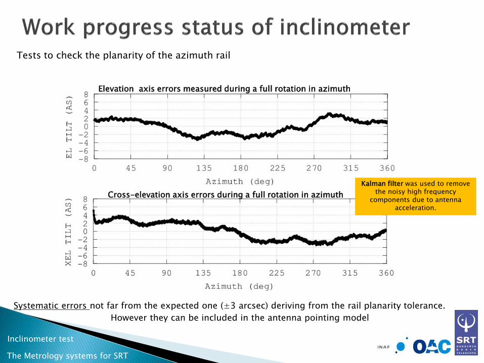
Tests to check the planarity of the azimuth rail
Systematic errors not far from the expected one (±3 arcsec) deriving from the rail planarity tolerance. However they can be included in the antenna pointing model
Cross-elevation axis errors during a full rotation in azimuth
Elevation axis errors measured during a full rotation in azimuth
Kalman filter was used to remove the noisy high frequency
components due to antenna acceleration.

The Metrology systems for SRT
Inclinometer test
Inclinometer measurement during astronomical observation on a circumpolar radio source at 23 GHz (K-band receiver) from sunrise to noon.
Residual offsets calculated from a Gaussian fit of the antenna
beam after a cross-scan.
+ residual offset - inclinometer meas
+ residual offset - inclinometer meas
Elevation axis errors caused by antenna thermal deformations
Azimuth axis errors caused by antenna thermal deformations
Kalman filter was used to remove the noisy high frequency
components from inclinometer meas. due to antenna
acceleration.
NOTE. With the antenna pointing model working, residual offsets take into account both alidade and quadripod temperature variation (not only alidade as in the inclinometer measurement)

The Metrology systems for SRT
Temperarure probes
The number and position of the temperature probes on SRT structure were inferred by FEM model:
• 16 probes on the alidade • 8 probes on the quadrupod
Probes installation, cabling and interfacing with Beckhoff embeddes pc will be soon accomplished

The Metrology systems for SRT
Optical laser PSD
z
x y
PSDs can measure X, Y, Z translation (derived by two X measur.) and X,Y axes rotation of the subreflector. But not installed yet.
Two PSD for a real-time measurement of the secondary mirror misalignments will be soon installed behind the central panel of the sub-reflector
PSDs
sensitive area = 22.5 x 22.5 mm^2 Operational spectral range : 350-1100 nm
power range: 0.1-5 mW Accuracy over calibrate area= ± 50 µm
Angular measur. range = ± 2 deg Angular resolution = ± 1 arcsec
23
m
Laser diodes
Wavelength = 658 nm Power = 10 mW

The Metrology systems for SRT
Other systems
Real-time photogrammetry Radial optical linear sensors
Laser diode
Sensor package
Both systems are under test for a real time measurement of primary surface panel deformations
develop a simulation environment for photogrammetric measurement
obtain the best configuration of the camera suitable for the SRT during operations
Project funded by Sardinian regional government to:

The Metrology systems for SRT
Future plans
Include inclinometer, PSD and temperature probe data in the antenna pointing model in order to compensate for alidade and quadrupod thermal deformations and monitor the antenna temperature in real time
Beside the traditional holography, test the Out-of-Focus method on SRT
for a quasi-real time mapping of the primary surface deformations due even to thermal gradients
Finally, approach a closed-loop control for a quasi-real time correction
of pointing errors and primary surface deformations

The Metrology systems for SRT
Conclusions
At the present, the SRT scientific validation is keep going without intermission to make SRT ready to be shared with the radioastronomy community as soon as possible
Even if the metrology systems, here presented, are not still ready, they look like very promising to preserve high antenna performances even at the higher frequencies
Step by step we are getting confidence to reach the closed-loop control of the SRT metrology, i.e. final goal for the SRT metrology.
Thanks for you attention!
Any questions?