presentation on gdt (2)
TRANSCRIPT
7/28/2019 Presentation on GDT (2)
http://slidepdf.com/reader/full/presentation-on-gdt-2 1/34
7/28/2019 Presentation on GDT (2)
http://slidepdf.com/reader/full/presentation-on-gdt-2 2/34
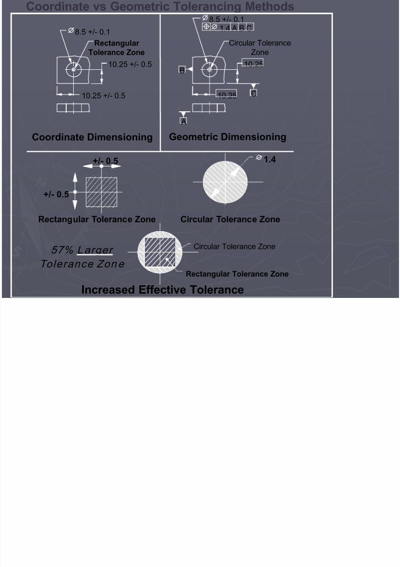
10.25 +/- 0.5
10.25 +/- 0.5
8.5 +/- 0.1Rectangular
Tolerance Zone
10.25
10.25
8.5 +/- 0.1
Circular ToleranceZone
B
A
C
Coordinate vs Geometric Tolerancing Methods
Coordinate Dimensioning Geometric Dimensioning
Rectangular Tolerance Zone Circular Tolerance Zone
1.4+/- 0.5
+/- 0.5
57% L arger Tolerance Zon e
Circular Tolerance Zone
Rectangular Tolerance Zone
Increased Effective Tolerance
1.4 A B C
7/28/2019 Presentation on GDT (2)
http://slidepdf.com/reader/full/presentation-on-gdt-2 3/34
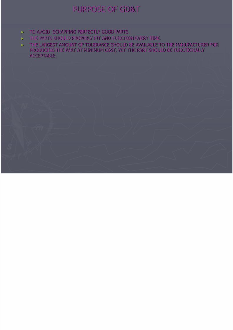
PURPOSE OF GD&T
► TO AVOID SCRAPPING PERFECTLY GOOD PARTS.►
THE PARTS SHOULD PROPERLY FIT AND FUNCTION EVERY TIME.► THE LARGEST AMOUNT OF TOLERANCE SHOULD BE AVAILABLE TO THE MANUFACTURER FOR PRODUCING THE PART AT MINIMUM COST, YET THE PART SHOULD BE FUNCTIONALLY
ACCEPTABLE.
7/28/2019 Presentation on GDT (2)
http://slidepdf.com/reader/full/presentation-on-gdt-2 4/34
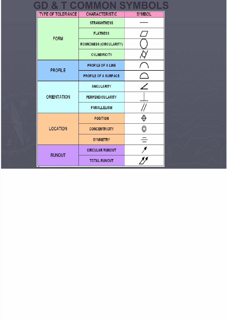
GD & T COMMON SYMBOLS

7/28/2019 Presentation on GDT (2)
http://slidepdf.com/reader/full/presentation-on-gdt-2 5/34
GD & T COMMON SYMBOLS

7/28/2019 Presentation on GDT (2)
http://slidepdf.com/reader/full/presentation-on-gdt-2 6/34
COMPONENTS OF FEATURE CONTROL FRAME
7/28/2019 Presentation on GDT (2)
http://slidepdf.com/reader/full/presentation-on-gdt-2 7/34
Terms in GD&T
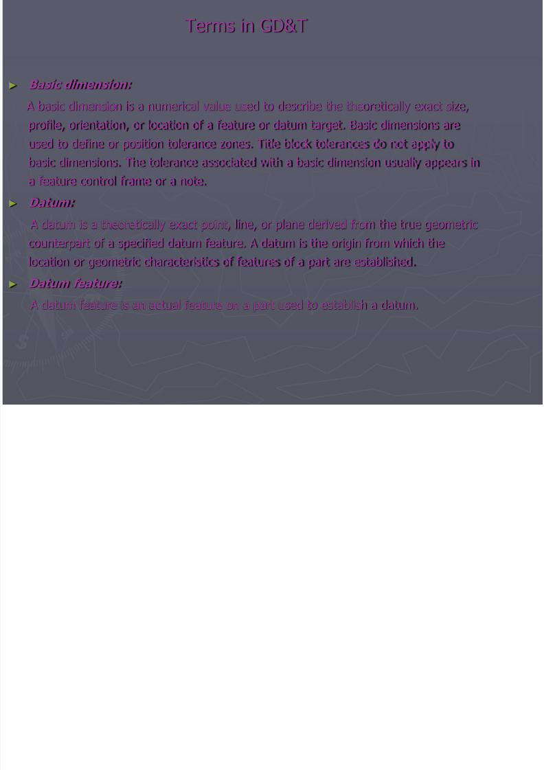
► Basic dimension:
A basic dimension is a numerical value used to describe the theoretically exact size,profile, orientation, or location of a feature or datum target. Basic dimensions areused to define or position tolerance zones. Title block tolerances do not apply tobasic dimensions. The tolerance associated with a basic dimension usually appears ina feature control frame or a note.
► Datum:
A datum is a theoretically exact point, line, or plane derived from the true geometriccounterpart of a specified datum feature. A datum is the origin from which thelocation or geometric characteristics of features of a part are established.
► Datum feature: A datum feature is an actual feature on a part used to establish a datum.

7/28/2019 Presentation on GDT (2)
http://slidepdf.com/reader/full/presentation-on-gdt-2 8/34
► Feature:
A feature is a physical portion of a part, such as a flat surface, pin, hole, tab, or slot.
►
Feature of size (also Size Feature and Feature Subject to Size Variations):Features of size are features that have a size dimension. A feature of size takes fourforms:
Cylindrical surfaces
Two opposed parallel surfaces
A spherical surface
Two opposed elements
Cylindrical surfaces and two opposed parallel surfaces are the most common featuresof size.
► True position:
True position is the theoretically exact location of a feature established by basicdimensions. Tolerance zones are located at true position.
7/28/2019 Presentation on GDT (2)
http://slidepdf.com/reader/full/presentation-on-gdt-2 9/34
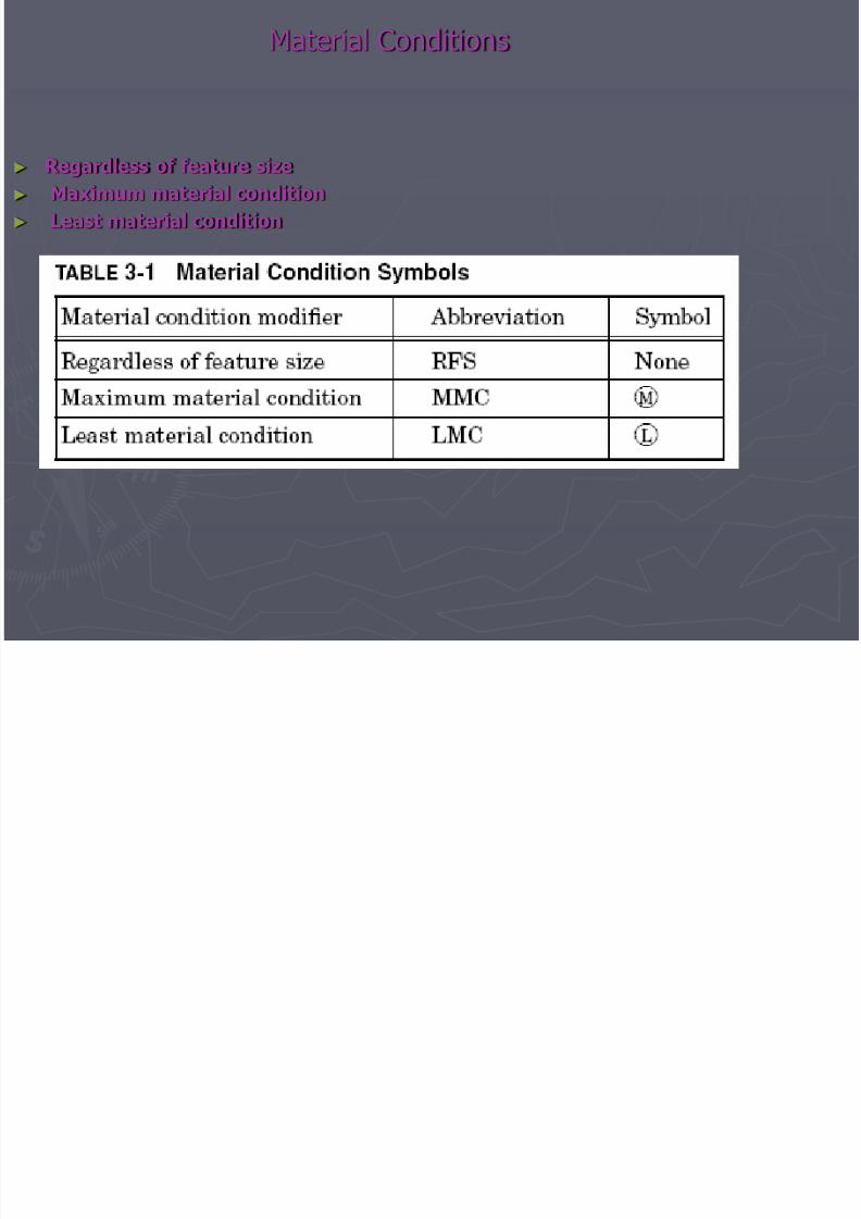
Material Conditions
► Regardless of feature size► Maximum material condition► Least material condition

7/28/2019 Presentation on GDT (2)
http://slidepdf.com/reader/full/presentation-on-gdt-2 10/34
Maximum Material Condition (MMC)► The maximum material condition of a feature of size is the maximum
amount of material within the stated limits of size, for example, themaximum shaft diameter or the minimum hole diameter
Least material condition (LMC): ► The least material condition of a feature of size is the least amount of
material within the stated limits of size. For example, the minimum shaftdiameter or the maximum hole diameter.
Regardless of feature size (RFS): ► Regardless of feature size is a material condition modifier used in a feature
control frame to indicate that a geometric tolerance or datum referenceapplies at each increment of size of the feature within its limits of size. RFSspecifies that no bonus tolerance is allowed.
7/28/2019 Presentation on GDT (2)
http://slidepdf.com/reader/full/presentation-on-gdt-2 11/34
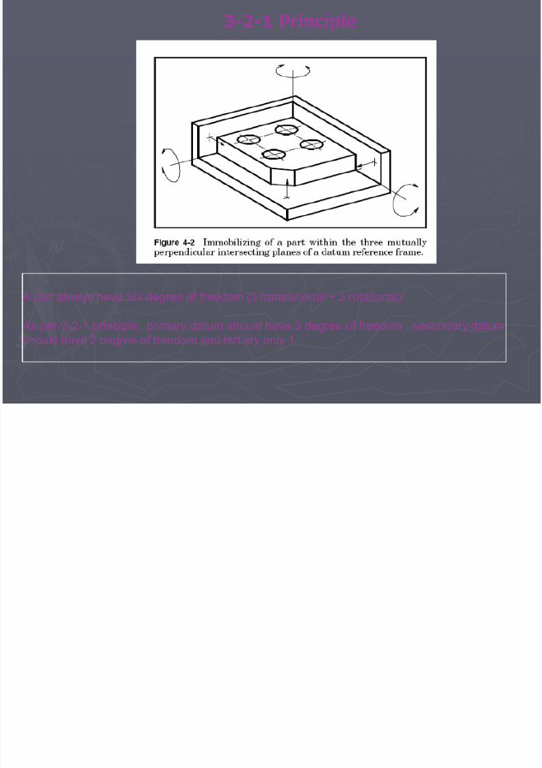
3-2-1 Principle
A part always have Six degree of freedom (3 translational + 3 rotational)
As per 3-2-1 principle , primary datum should have 3 degree of freedom , secondary datumshould have 2 degree of freedom and tertiary only 1.

7/28/2019 Presentation on GDT (2)
http://slidepdf.com/reader/full/presentation-on-gdt-2 12/34
RULES OF GD&T
There are four rules that apply to drawings in general, and to GD&T in particular.► Rule #1 states that where only a tolerance of size is specified, the limits of size of an
individual feature of size prescribe the extent to which variations in its geometric form ,as well as its size , are allowed.
► Rule #2 states that RFS automatically applies, in a feature control frame, to individualtolerances of size features and to datum features of size. MMC and LMC must bespecified when these conditions are required.
► Rule #3 The pitch diameter rule
Each tolerance of orientation or position and datum reference specified for screw threadsapplies to the axis of the thread derived from the pitch diameter. Exceptions to this rulemay be specified by placing a note, such as MAJOR DIA or MINOR DIA, beneath thefeature control frame, or beneath or adjacent to, the datum feature symbol.
► Rule #4 The virtual condition ruleWhere a datum feature of size is controlled by a geometric tolerance and thatdatum is specified as a secondary or tertiary datum , the datum applies at virtualcondition with respect to orientation .
7/28/2019 Presentation on GDT (2)
http://slidepdf.com/reader/full/presentation-on-gdt-2 13/34
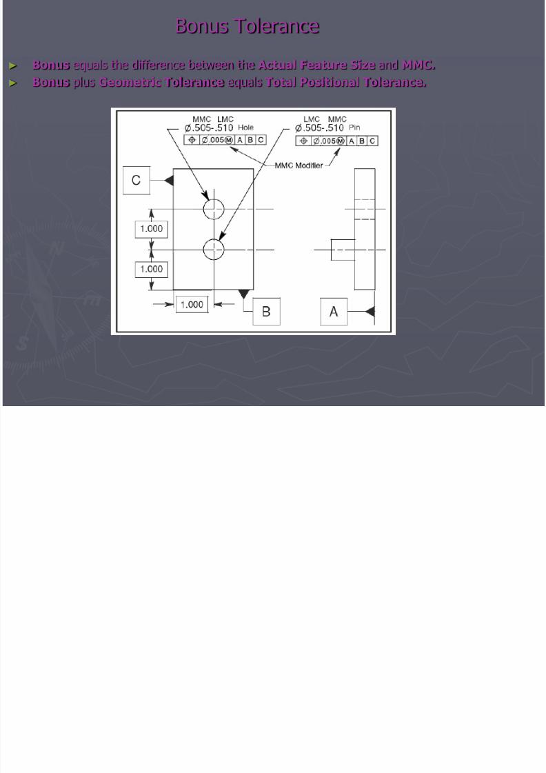
Bonus Tolerance
► Bonus equals the difference between the Actual Feature Size and MMC.► Bonus plus Geometric Tolerance equals Total Positional Tolerance.

7/28/2019 Presentation on GDT (2)
http://slidepdf.com/reader/full/presentation-on-gdt-2 14/34
Virtual condition
The virtual condition of a feature specified at MMC is a constant boundary generatedby the collective effects of the MMC limit of size of a feature and the specified
geometric tolerance. Features specified with an LMC modifier also have a virtualcondition.
Virtual condition calculations:
External Features (Pin)
MMCPlus Geometric Tolerance @ MMC
Internal Features (Hole)MMC Minus Geometric Tolerance @ MMC
7/28/2019 Presentation on GDT (2)
http://slidepdf.com/reader/full/presentation-on-gdt-2 15/34
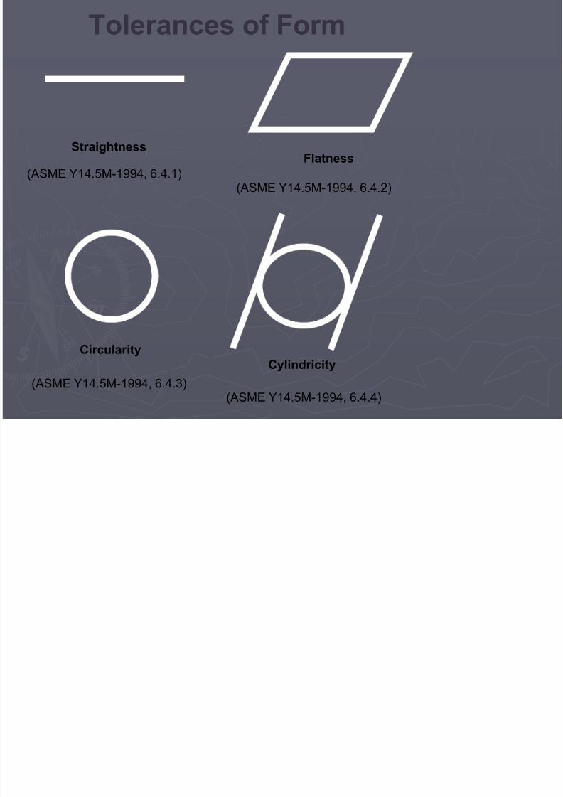
Tolerances of Form
StraightnessFlatness
CircularityCylindricity
(ASME Y14.5M-1994, 6.4.1)
(ASME Y14.5M-1994, 6.4.3)
(ASME Y14.5M-1994, 6.4.2)
(ASME Y14.5M-1994, 6.4.4)
7/28/2019 Presentation on GDT (2)
http://slidepdf.com/reader/full/presentation-on-gdt-2 16/34
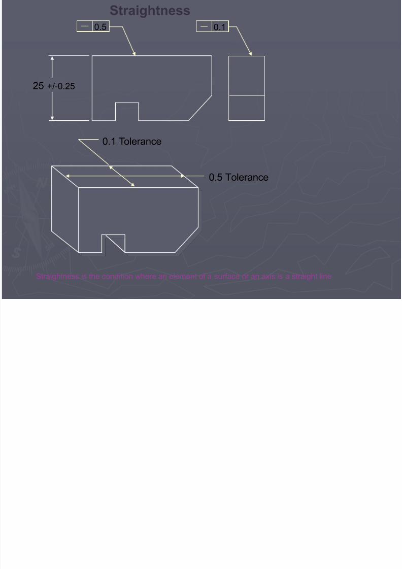
25 +/-0.25
0.1 Tolerance
0.5 Tolerance
Straightness is the condition where an element of a surface or an axis is a straight line
Straightness0.5 0.1
7/28/2019 Presentation on GDT (2)
http://slidepdf.com/reader/full/presentation-on-gdt-2 17/34
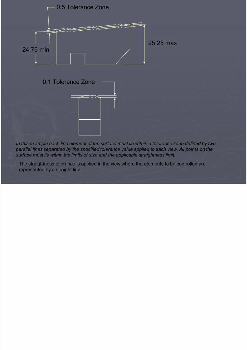
25.25 max24.75 min
0.5 Tolerance Zone
0.1 Tolerance Zone
The straightness tolerance is applied in the view where the elements to be controlled arerepresented by a straight line
In this example each line element of the surface must lie within a tolerance zone defined by two parallel lines separated by the specified tolerance value applied to each view. All points on thesurface must lie within the limits of size and the applicable straightness limit.

7/28/2019 Presentation on GDT (2)
http://slidepdf.com/reader/full/presentation-on-gdt-2 18/34
Flatness
Flatness is the condition of a surface having all elements in one plane. Flatness must fall withinthe limits of size. The flatness tolerance must be less than the size tolerance.
25 +/-0.25
24.75 min25.25 max
0.1
0.1 Tolerance Zone
0.1 Tolerance Zone
In this example the entire surface must lie within a tolerance zone defined by two parallel planesseparated by the specified tolerance value. All points on the surface must lie within the limits of size and the flatness limit.

7/28/2019 Presentation on GDT (2)
http://slidepdf.com/reader/full/presentation-on-gdt-2 19/34
Circularity is the condition of a surface where all points of the surface intersected by any planeperpendicular to a common axis are equidistant from that axis. The circularity tolerance must be less thanthe size tolerance
9090
0.1
Circularity (Roundness)
In this example each circular element of the surface must lie within a tolerance zone defined by two concentric circles separated by the specified tolerance value. All points on the surface must lie within the limits of size and the circularity limit.
0.10.1 Wide Tolerance Zone

7/28/2019 Presentation on GDT (2)
http://slidepdf.com/reader/full/presentation-on-gdt-2 20/34
Cylindricity
Cylindricity is the condition of a surface of revolution in which all points are equidistant from acommon axis. Cylindricity is a composite control of form which includes circularity (roundness),straightness, and taper of a cylindrical feature.
0.1 Tolerance Zone
MMC
0.1
In this example the entire surface must lie within a tolerance zone defined by two concentric cylindersseparated by the specified tolerance value. All points on the surface must lie within the limits of sizeand the cylindricity limit.
7/28/2019 Presentation on GDT (2)
http://slidepdf.com/reader/full/presentation-on-gdt-2 21/34
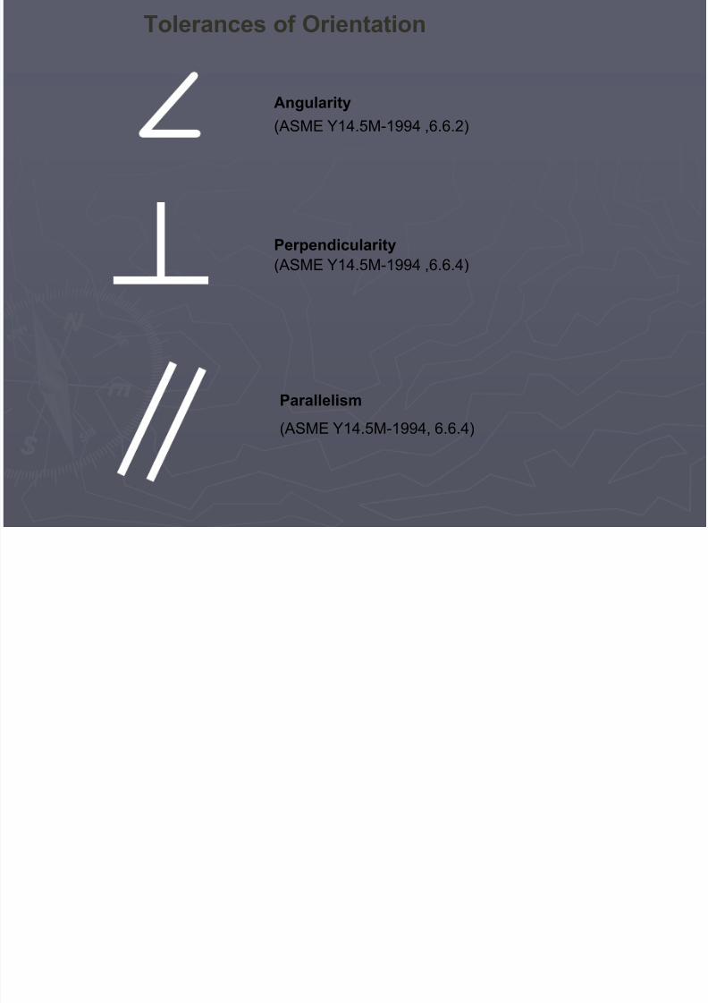
Tolerances of Orientation
Angularity
(ASME Y14.5M-1994 ,6.6.2)
Perpendicularity(ASME Y14.5M-1994 ,6.6.4)
Parallelism
(ASME Y14.5M-1994, 6.6.4)
A l i

7/28/2019 Presentation on GDT (2)
http://slidepdf.com/reader/full/presentation-on-gdt-2 22/34
Angularity(Feature Surface to Datum Surface)
Angularity is the condition of the planar feature surface at a specified angle (other than 90 degrees)to the datum reference plane, within the specified tolerance zone.
A
20 +/-0.5
30 o
A
19.5 min
0.3 WideTolerance
Zone
30 o
A
20.5 max
0.3 WideTolerance
Zone
30 o
The to lerance zone in th i s example i s def ined by tw o para l l el p lanes or ien ted a t the spec i f i ed angle to the d a tum reference p lane.
0.3 A
P di l it (F t S f t D t S f )

7/28/2019 Presentation on GDT (2)
http://slidepdf.com/reader/full/presentation-on-gdt-2 23/34
0.3 A
A
0.3 WideTolerance Zone
A A
Perpendicularity is the condition of the planar feature surface at a right angleto the datum reference plane, within the specified tolerance zone.
Perpendicularity (Feature Surface to Datum Surface)
0.3 WideTolerance Zone
The to lerance zone in th is example is def ined by two paralle l planes or ien ted perpendicu lar to the da tum reference p lane .
Parallelism (Feature Surface to Datum Surface)

7/28/2019 Presentation on GDT (2)
http://slidepdf.com/reader/full/presentation-on-gdt-2 24/34
25.5 max
Parallelism is the condition of the planar feature surface equidistant at all pointsfrom the datum reference plane, within the specified tolerance zone.
Parallelism (Feature Surface to Datum Surface)
The to lerance zone in th is example is def ined by two paralle l planes oriented p arallel to the datum r eferenc e plane.
0.3 A
A
25 +/-0.5
0.3 Wide Tolerance Zone
A
24.5 min
0.3 Wide Tolerance Zone
A

7/28/2019 Presentation on GDT (2)
http://slidepdf.com/reader/full/presentation-on-gdt-2 25/34
Tolerances of Runout
Total Runout
(ASME Y14.5M-1994 ,6.7.1.2.2)
Circular Runout
(ASME Y14.5M-1994 ,6.7.1.2.2)
Circular Runout

7/28/2019 Presentation on GDT (2)
http://slidepdf.com/reader/full/presentation-on-gdt-2 26/34
Runout refers to the result of placing a solid of revolution on a spindle such as a lathe,and rotating the part about its central axis while measuring with a dial indicator itssurface deviation from perfect roundness. With circular runout, the dial indicator is notmoved along the direction of the axis of the part. Circular runout is therefore applied
independently at each station along the length of the part as the part is rotatedthrough 360 degrees.
Circular Runout
Total runout involves moving the dial indicator along the length of the part while the
part is rotated, so that it controls the cumulative variations of circularity, cylindricity,straightness, coaxiality, angularity, taper, and profile.
Total Runout
7/28/2019 Presentation on GDT (2)
http://slidepdf.com/reader/full/presentation-on-gdt-2 27/34
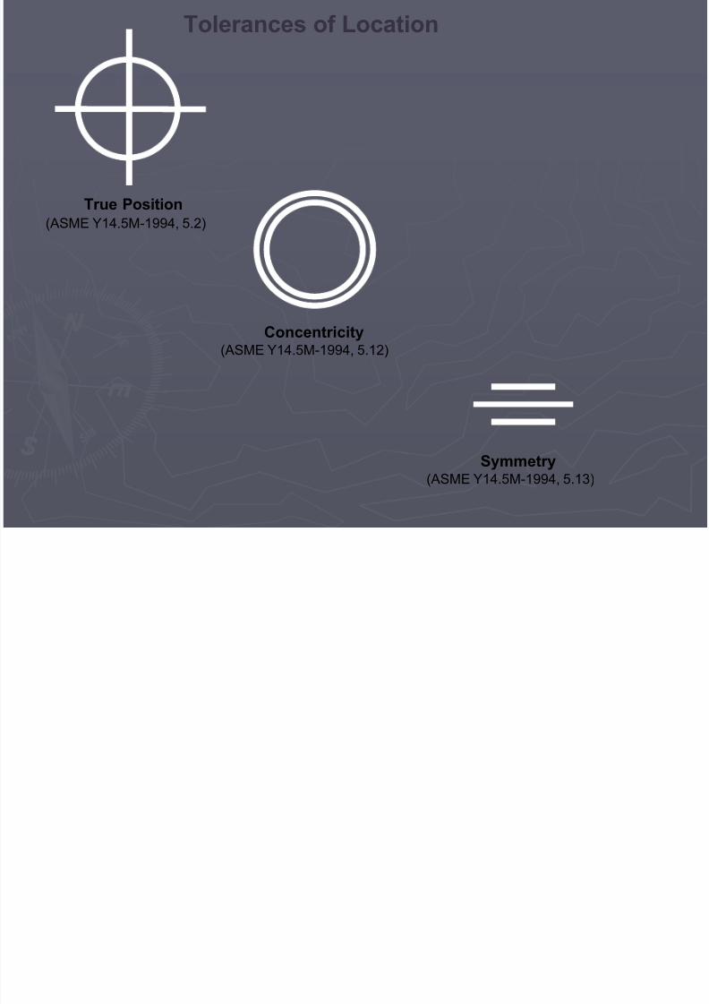
Tolerances of Location
True Position(ASME Y14.5M-1994, 5.2)
Concentricity(ASME Y14.5M-1994, 5.12)
Symmetry(ASME Y14.5M-1994, 5.13)
T P iti

7/28/2019 Presentation on GDT (2)
http://slidepdf.com/reader/full/presentation-on-gdt-2 28/34
A theoretical tolerance zone located at true position of thetoleranced feature within which the center point, axis, orcenter plane of the feature may vary from true position
True Position(ASME Y14.5M-1994, 5.2)
True Position
Means This
Location (Concentricity)

7/28/2019 Presentation on GDT (2)
http://slidepdf.com/reader/full/presentation-on-gdt-2 29/34
Location (Concentricity)
A
15.9515.90 As Shown on Drawing
Derived Median Points of Diametrically Opposed Elements
Axis of DatumFeature A
Within the limits of size and regardless of feature size, all median points of diametricallyopposed elements must lie within a 0.5 cylindrical tolerance zone. The axis of thetolerance zone coincides with the axis of datum feature A. Concentricity can only be appliedon an RFS basis.
0.5 A6.35 +/- 0.05
0.5 CoaxialTolerance Zone
Datum Features at RFS
Location (Symmetry)

7/28/2019 Presentation on GDT (2)
http://slidepdf.com/reader/full/presentation-on-gdt-2 30/34
Location (Symmetry)
A
15.9515.90
0.5 A6.35 +/- 0.05
Derived Median Points
Center Plane of Datum Feature A
0.5 WideTolerance Zone
Within the limits of size and regardless of feature size, all median points of opposed elements must lie between two parallel planes equally disposed aboutdatum plane A, 0.5 apart. Symmetry can only be applied on an RFS basis.
As Shown on Drawing
Datum Features at RFS
7/28/2019 Presentation on GDT (2)
http://slidepdf.com/reader/full/presentation-on-gdt-2 31/34
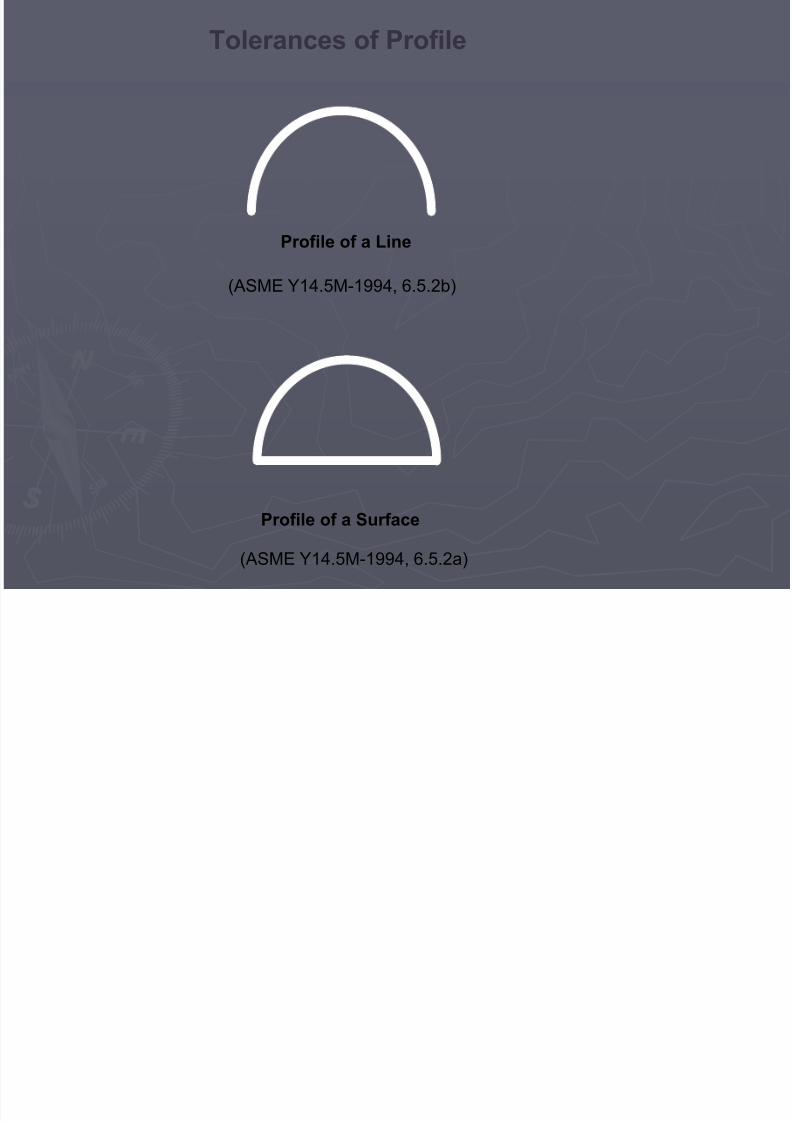
Tolerances of Profile
Profile of a Line
(ASME Y14.5M-1994, 6.5.2b)
Profile of a Surface
(ASME Y14.5M-1994, 6.5.2a)

7/28/2019 Presentation on GDT (2)
http://slidepdf.com/reader/full/presentation-on-gdt-2 32/34
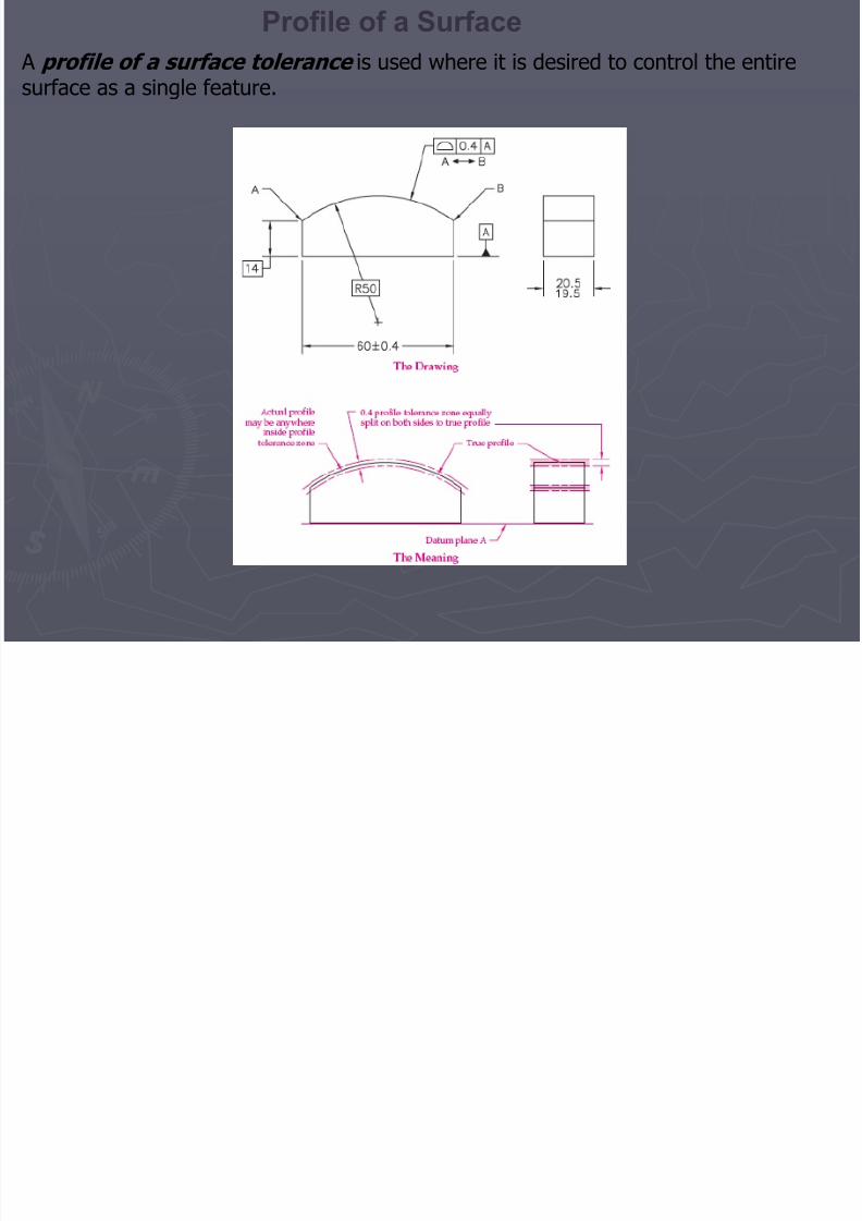
Profile of a Surface
7/28/2019 Presentation on GDT (2)
http://slidepdf.com/reader/full/presentation-on-gdt-2 33/34
A profile of a surface tolerance is used where it is desired to control the entiresurface as a single feature.
Profile of a Surface
7/28/2019 Presentation on GDT (2)
http://slidepdf.com/reader/full/presentation-on-gdt-2 34/34
THANK YOU