presentation invelox
DESCRIPTION
INVELOX, by contrast, funnels wind energy to ground –base generators. Wind is captured with a funnel and directed through a tapering passageway that naturally accelerates its flow. This stream of kinetic energy then drives a generator that is installed safely and economically at ground levelTRANSCRIPT
1
Invelox:CFD studyInstructor : Professor Yiannis AndreopoulosStudent : Saikat Das
2
Capture, accelerate, concentrate. The name INVELOX comes from this dedication to INcreasing the VELOcity of wind. What the technology produces-energy is affordable, abundant, safe, and clean.
INVELOX, by contrast, funnels wind energy to ground –base generators. Wind is captured with a funnel and directed through a tapering passageway that naturally accelerates its flow. This stream of kinetic energy then drives a generator that is installed safely and economically at ground level.
Bringing the airflow from top of the tower to ground level allows for greater power generation with much smaller turbine blades. It also allows for networking, allowing multiple towers to direct energy to the same generator.
How it works ?
3
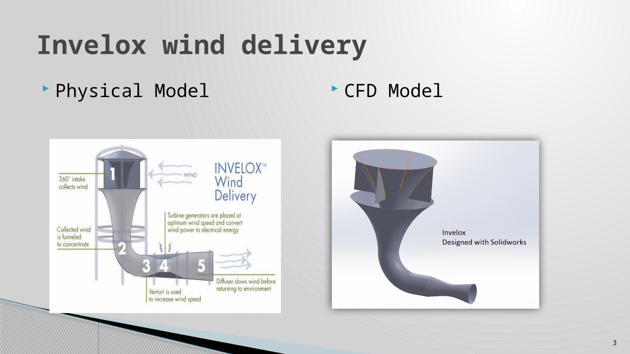
Physical Model CFD Model
Invelox wind delivery
4
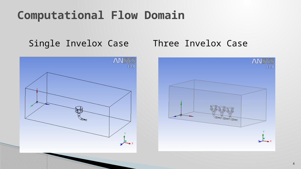
Single Invelox Case Three Invelox Case
Computational Flow Domain
5
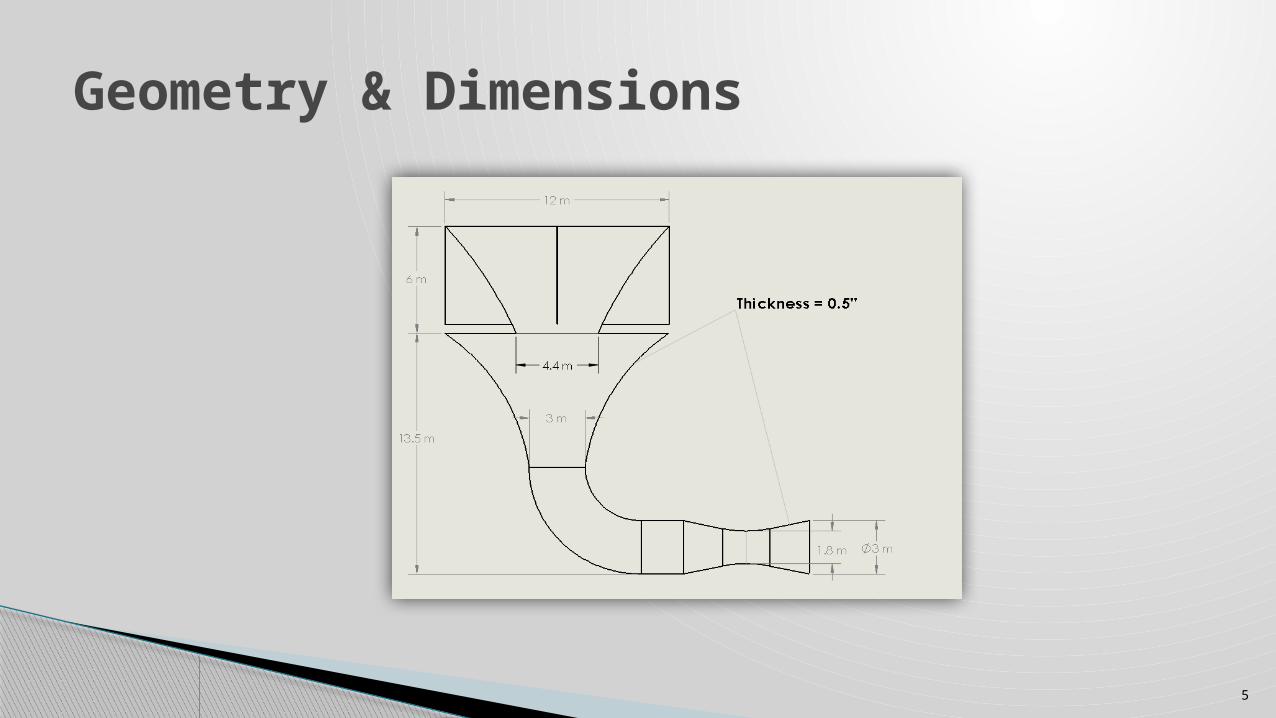
Geometry & Dimensions
6
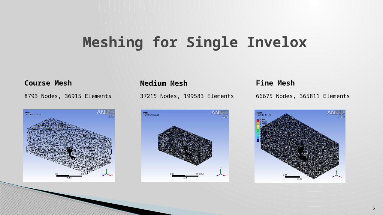
Meshing for Single Invelox
Course Mesh
8793 Nodes, 36915 Elements
Medium Mesh
37215 Nodes, 199583 Elements
Fine Mesh
66675 Nodes, 365811 Elements
7
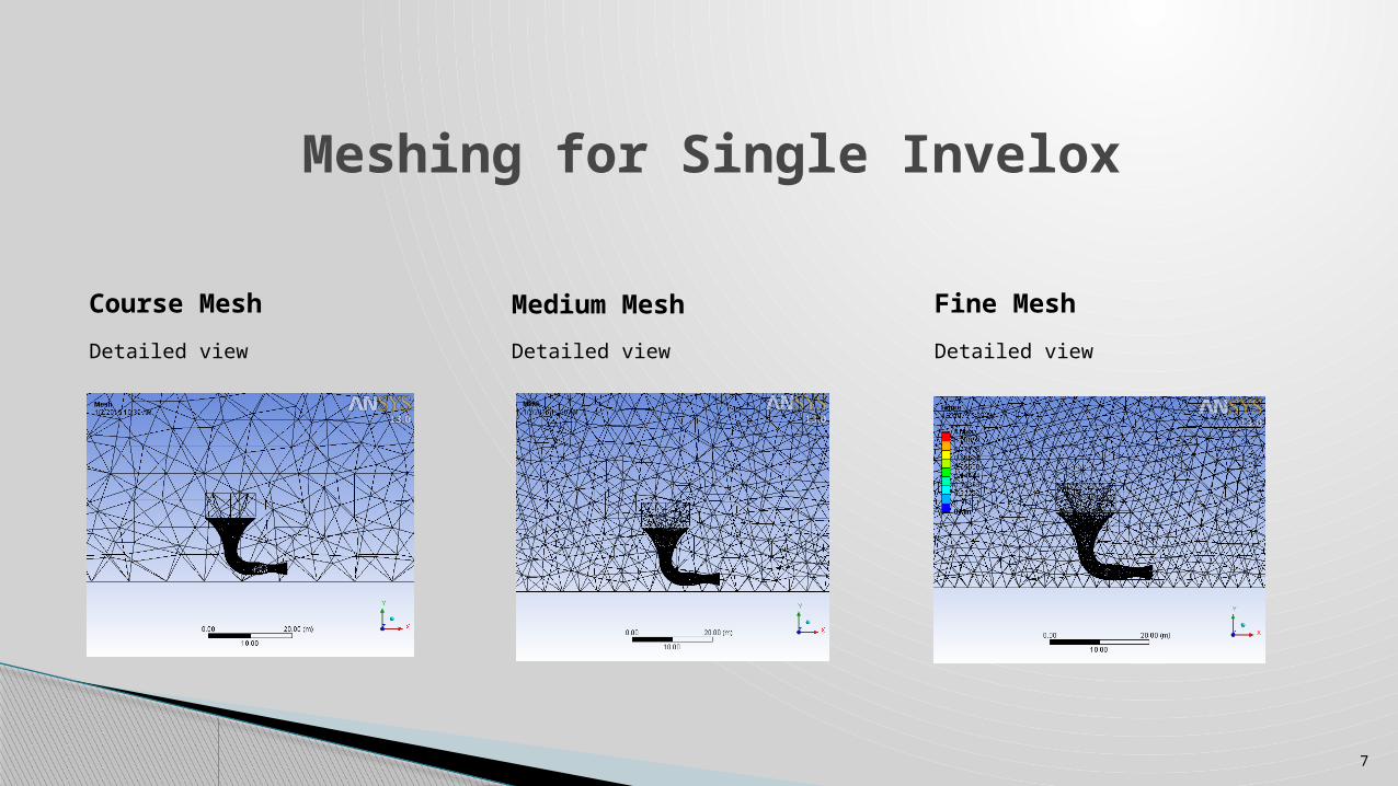
Meshing for Single Invelox
Course Mesh
Detailed view
Medium Mesh
Detailed view
Fine Mesh
Detailed view
8
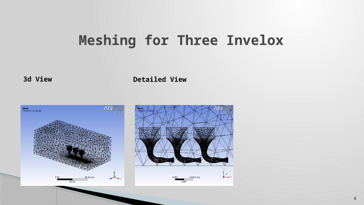
Meshing for Three Invelox
3d View Detailed View
9
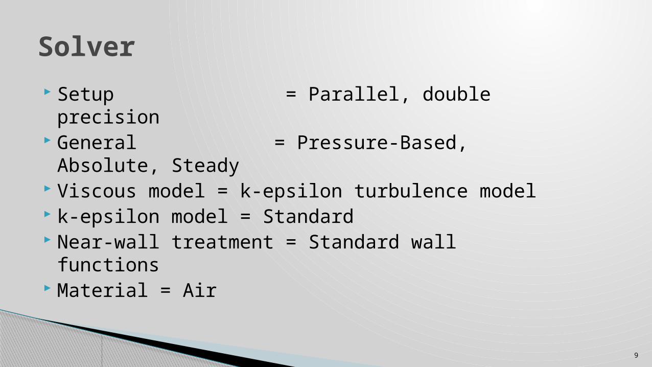
Setup = Parallel, double precision General = Pressure-Based, Absolute, Steady Viscous model = k-epsilon turbulence model k-epsilon model = Standard Near-wall treatment = Standard wall functions Material = Air
Solver
10
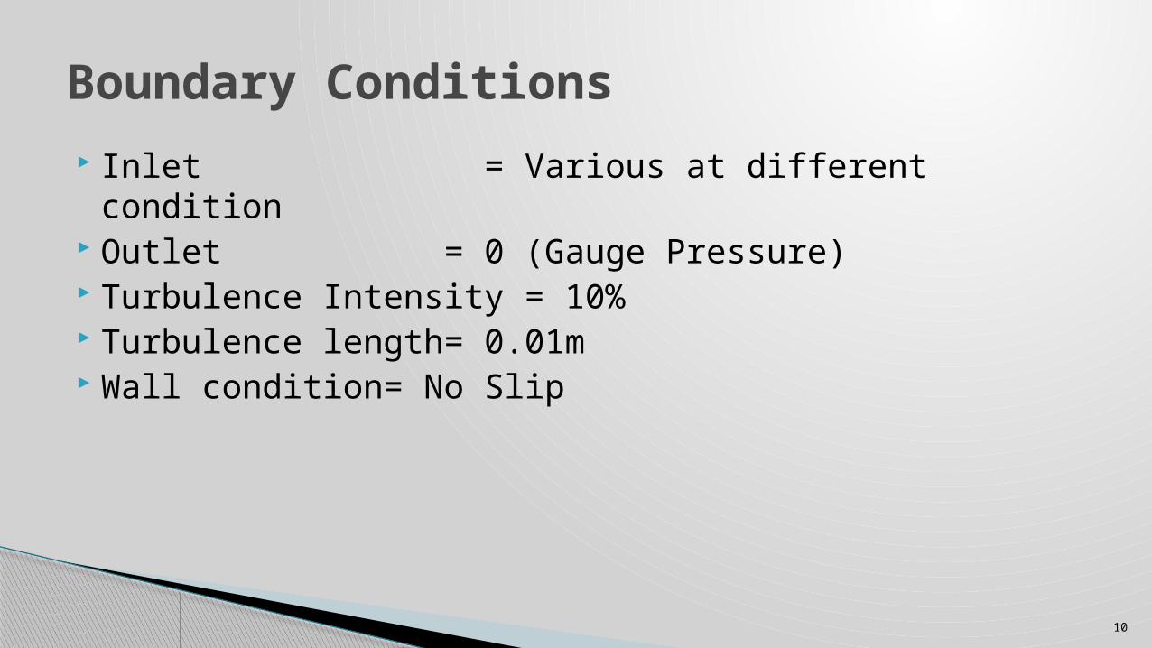
Inlet = Various at different condition Outlet = 0 (Gauge Pressure) Turbulence Intensity = 10% Turbulence length= 0.01m Wall condition= No Slip
Boundary Conditions
11
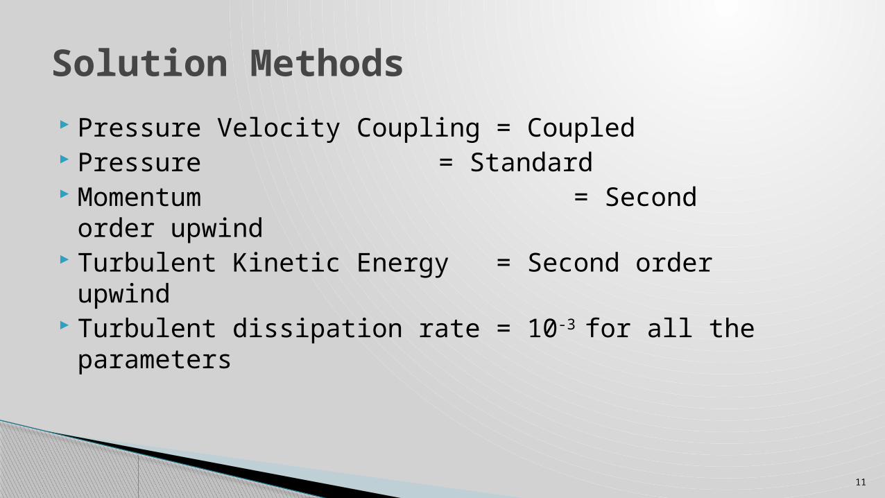
Pressure Velocity Coupling = Coupled Pressure = Standard Momentum = Second order upwind Turbulent Kinetic Energy = Second order upwind Turbulent dissipation rate = 10-3 for all the parameters
Solution Methods
12
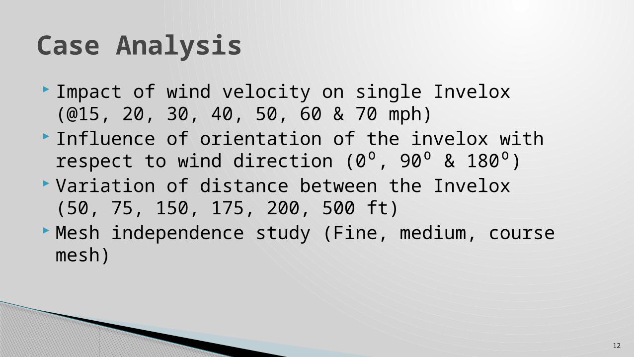
Impact of wind velocity on single Invelox (@15, 20, 30, 40, 50, 60 & 70 mph)
Influence of orientation of the invelox with respect to wind direction (0⁰, 90⁰ & 180⁰)
Variation of distance between the Invelox (50, 75, 150, 175, 200, 500 ft)
Mesh independence study (Fine, medium, course mesh)
Case Analysis
13
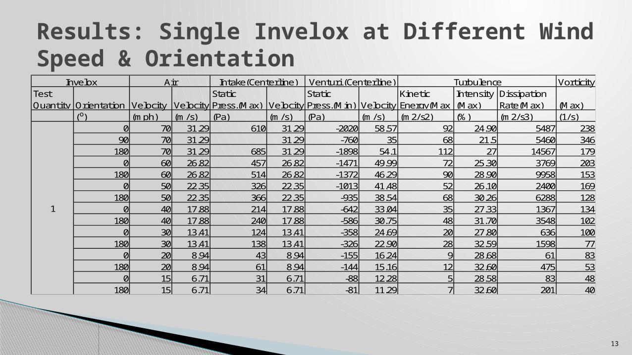
Results: Single Invelox at Different Wind Speed & Orientation
VorticityTest Quantity Orientation Velocity Velocity
Static Press.(Max) Velocity
Static Press.(Min) Velocity
Kinetic Energy(Max
Intensity(Max)
Dissipation Rate(Max) (Max)
(⁰) (mph) (m/s) (Pa) (m/s) (Pa) (m/s) (m2/s2) (%) (m2/s3) (1/s)0 70 31.29 610 31.29 -2020 58.57 92 24.90 5487 238
90 70 31.29 31.29 -760 35 68 21.5 5460 346180 70 31.29 685 31.29 -1898 54.1 112 27 14567 179
0 60 26.82 457 26.82 -1471 49.99 72 25.30 3769 203180 60 26.82 514 26.82 -1372 46.29 90 28.90 9958 153
0 50 22.35 326 22.35 -1013 41.48 52 26.10 2400 169180 50 22.35 366 22.35 -935 38.54 68 30.26 6288 128
0 40 17.88 214 17.88 -642 33.04 35 27.33 1367 134180 40 17.88 240 17.88 -586 30.75 48 31.70 3548 102
0 30 13.41 124 13.41 -358 24.69 20 27.80 636 100180 30 13.41 138 13.41 -326 22.90 28 32.59 1598 77
0 20 8.94 43 8.94 -155 16.24 9 28.68 61 83180 20 8.94 61 8.94 -144 15.16 12 32.60 475 53
0 15 6.71 31 6.71 -88 12.28 5 28.58 83 48180 15 6.71 34 6.71 -81 11.29 7 32.60 201 40
Invelox Air Intake(Centerline) Venturi (Centerline) Turbulence
1
14
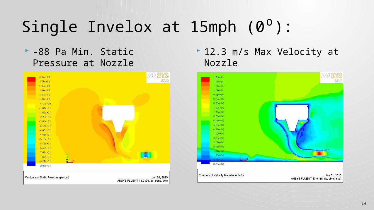
Single Invelox at 15mph (0⁰): -88 Pa Min. Static Pressure at
Nozzle 12.3 m/s Max Velocity at
Nozzle
15
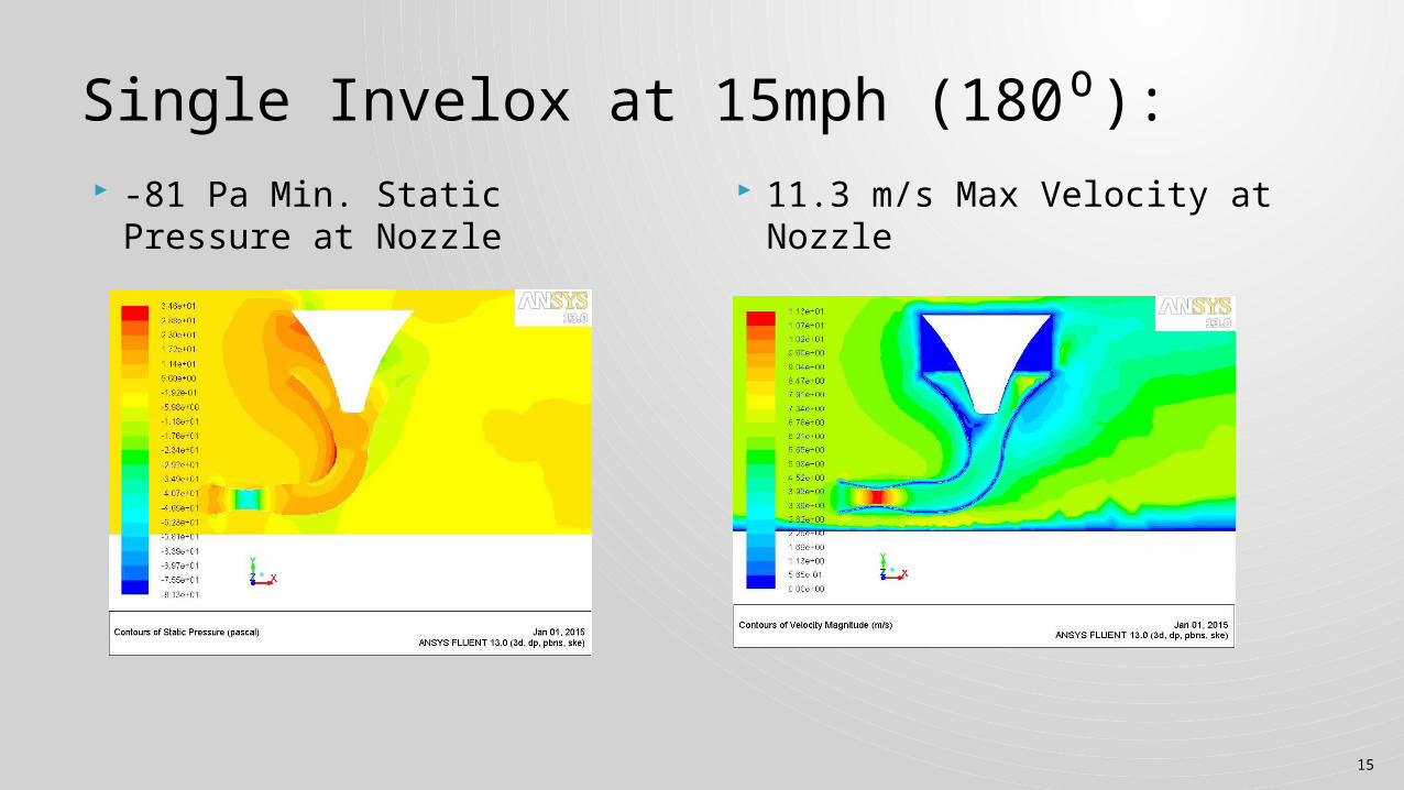
Single Invelox at 15mph (180⁰): -81 Pa Min. Static Pressure at
Nozzle 11.3 m/s Max Velocity at
Nozzle
16
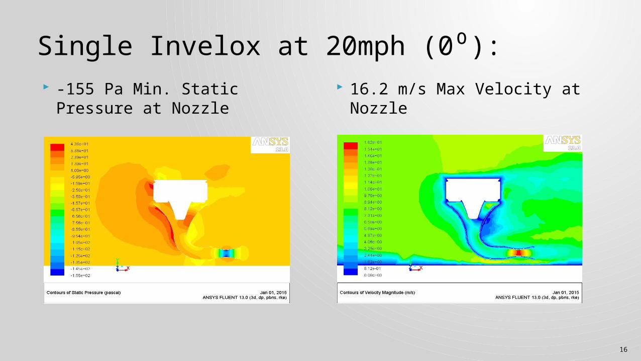
Single Invelox at 20mph (0⁰): -155 Pa Min. Static Pressure at
Nozzle 16.2 m/s Max Velocity at
Nozzle
17
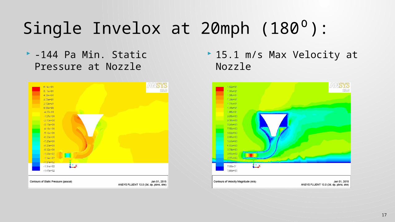
Single Invelox at 20mph (180⁰): -144 Pa Min. Static Pressure at
Nozzle 15.1 m/s Max Velocity at
Nozzle
18
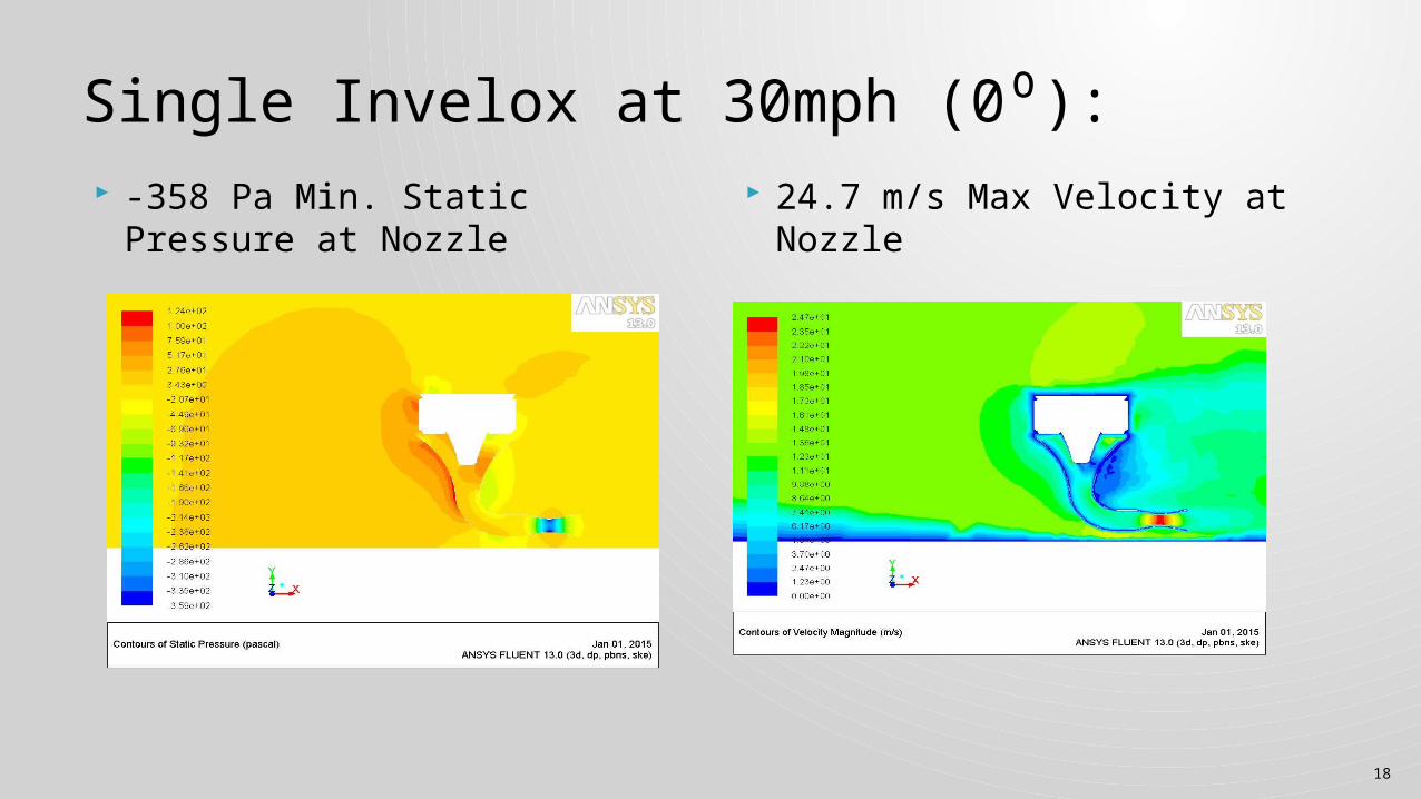
Single Invelox at 30mph (0⁰): -358 Pa Min. Static Pressure at
Nozzle 24.7 m/s Max Velocity at
Nozzle
19
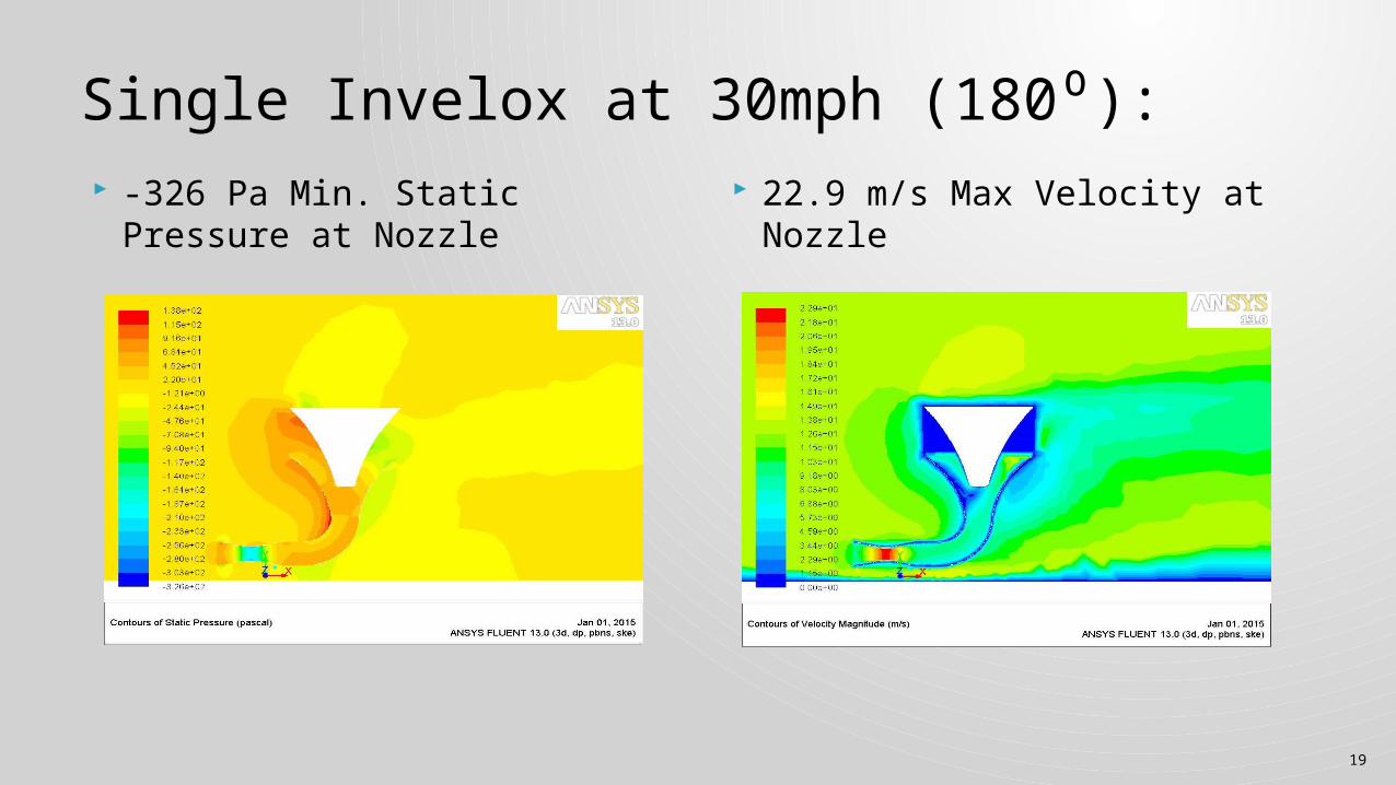
Single Invelox at 30mph (180⁰): -326 Pa Min. Static Pressure at
Nozzle 22.9 m/s Max Velocity at
Nozzle
20
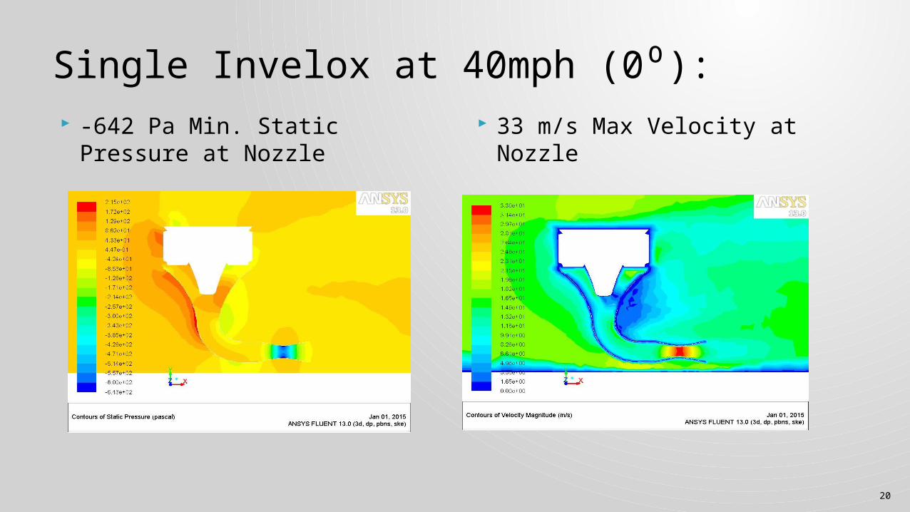
Single Invelox at 40mph (0⁰): -642 Pa Min. Static Pressure at
Nozzle 33 m/s Max Velocity at Nozzle
21
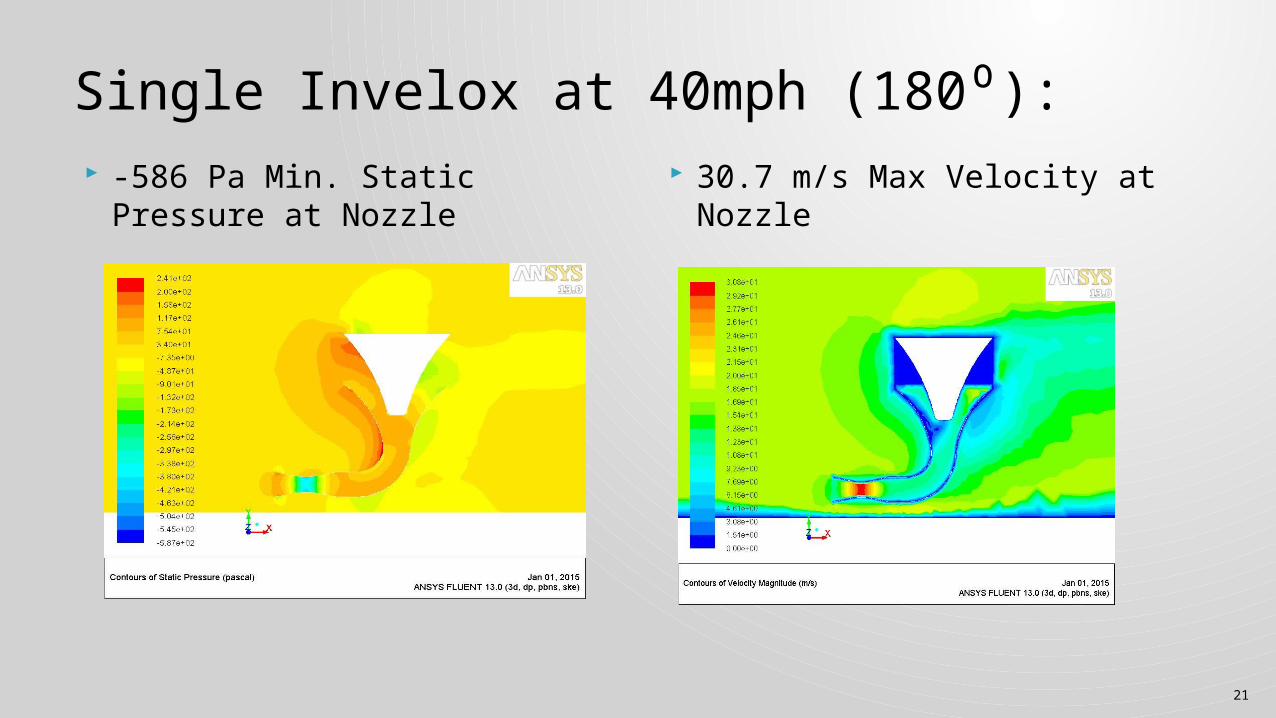
Single Invelox at 40mph (180⁰): -586 Pa Min. Static Pressure at
Nozzle 30.7 m/s Max Velocity at
Nozzle
22
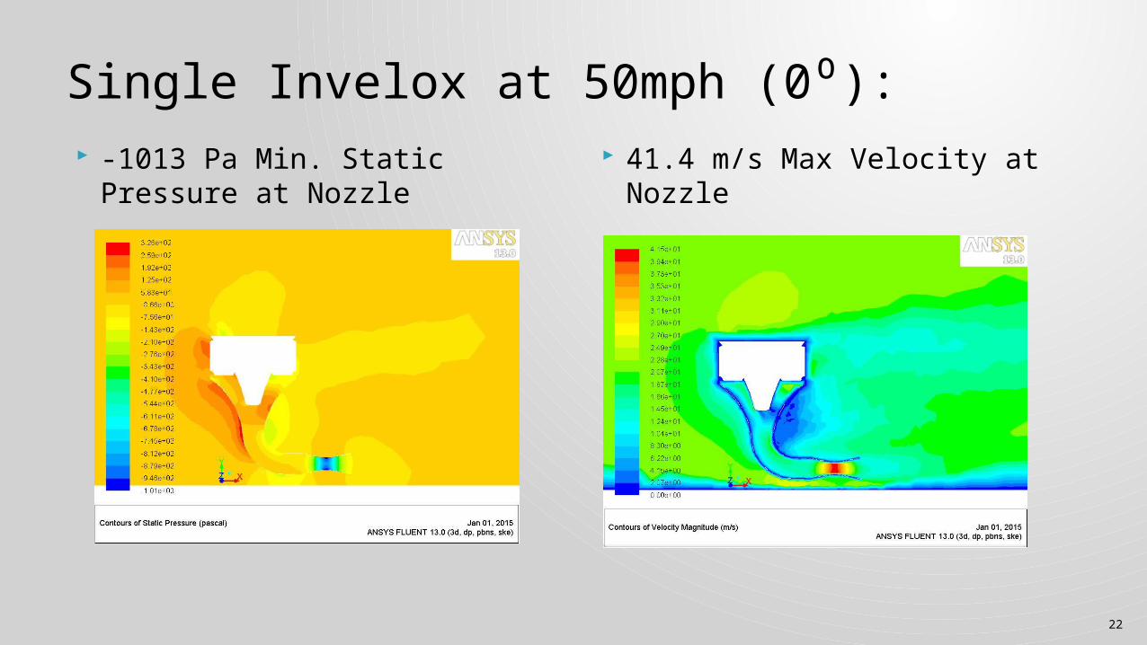
Single Invelox at 50mph (0⁰): -1013 Pa Min. Static Pressure
at Nozzle 41.4 m/s Max Velocity at
Nozzle
23
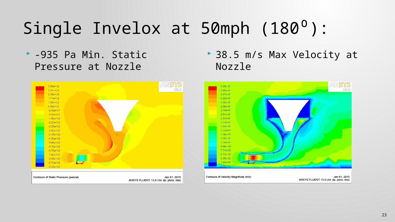
Single Invelox at 50mph (180⁰): -935 Pa Min. Static Pressure at
Nozzle 38.5 m/s Max Velocity at
Nozzle
24
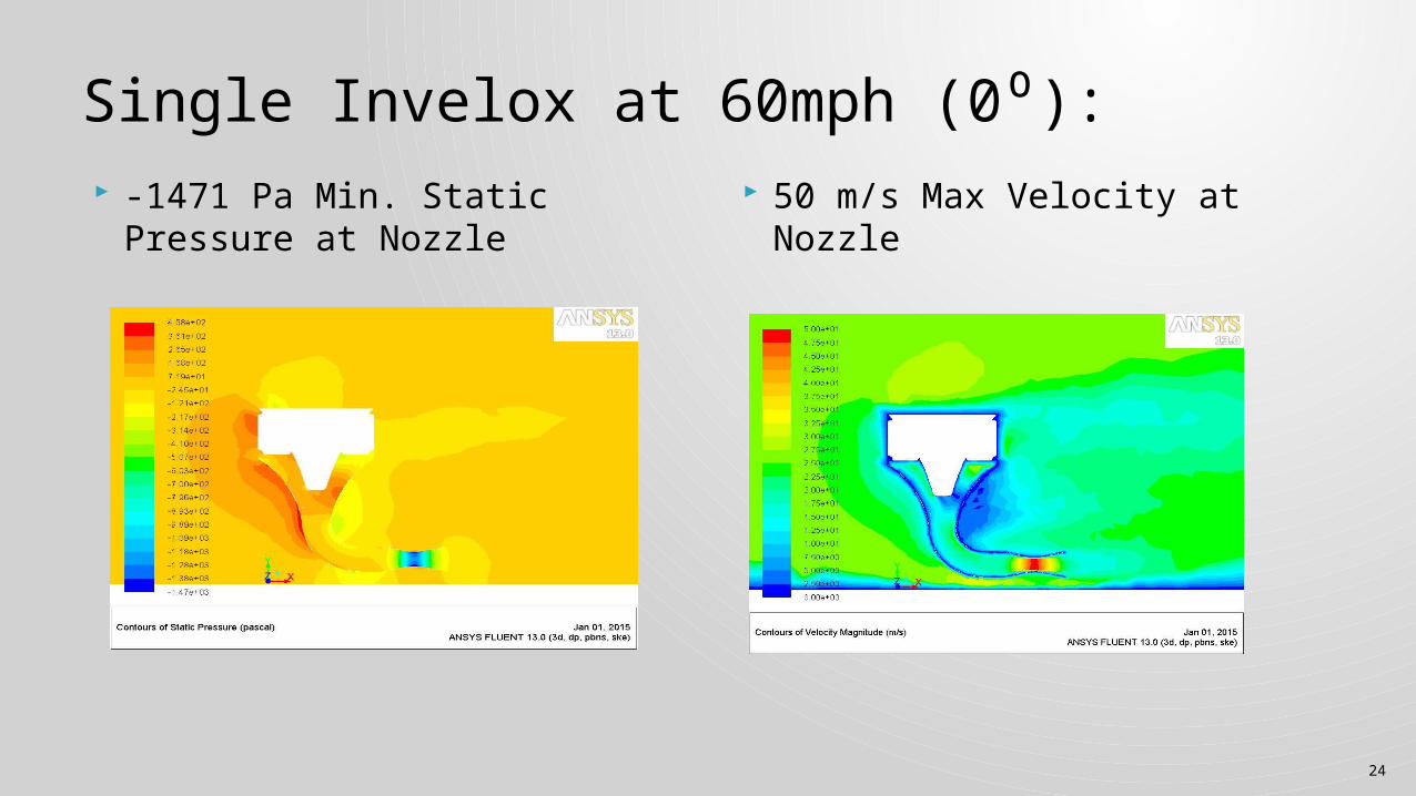
Single Invelox at 60mph (0⁰): -1471 Pa Min. Static Pressure
at Nozzle 50 m/s Max Velocity at Nozzle
25
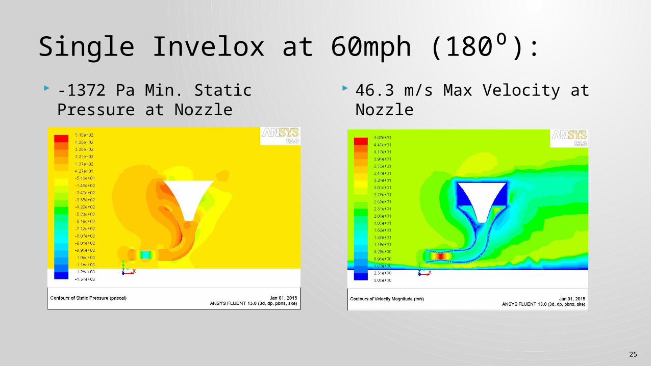
Single Invelox at 60mph (180⁰): -1372 Pa Min. Static Pressure
at Nozzle 46.3 m/s Max Velocity at
Nozzle
26
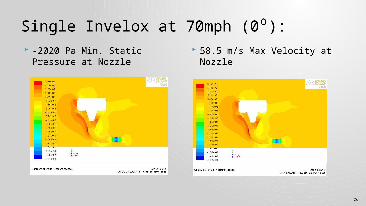
Single Invelox at 70mph (0⁰): -2020 Pa Min. Static Pressure
at Nozzle 58.5 m/s Max Velocity at
Nozzle
27
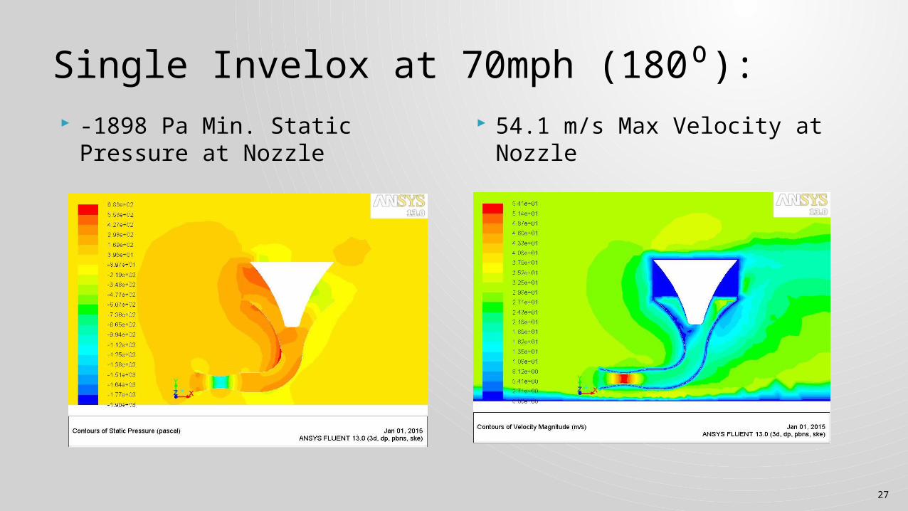
Single Invelox at 70mph (180⁰): -1898 Pa Min. Static Pressure
at Nozzle 54.1 m/s Max Velocity at
Nozzle
28
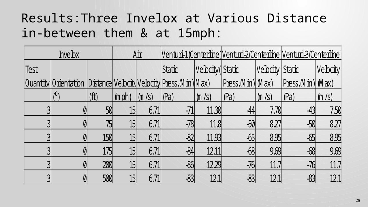
Results:Three Invelox at Various Distance in-between them & at 15mph:
Test Quantity Orientation Distance Velocity Velocity
Static Press.(Min)
Velocity(Max)
Static Press.(Min)
Velocity(Max)
Static Press.(Min)
Velocity(Max)
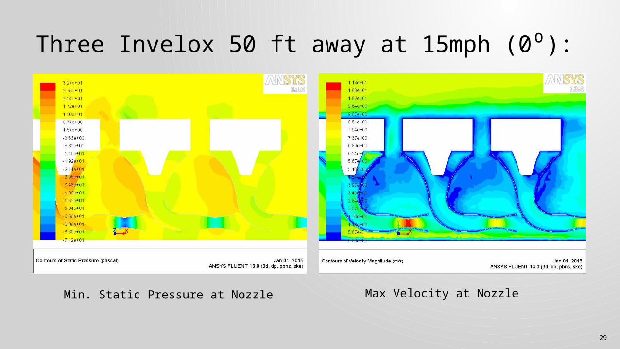
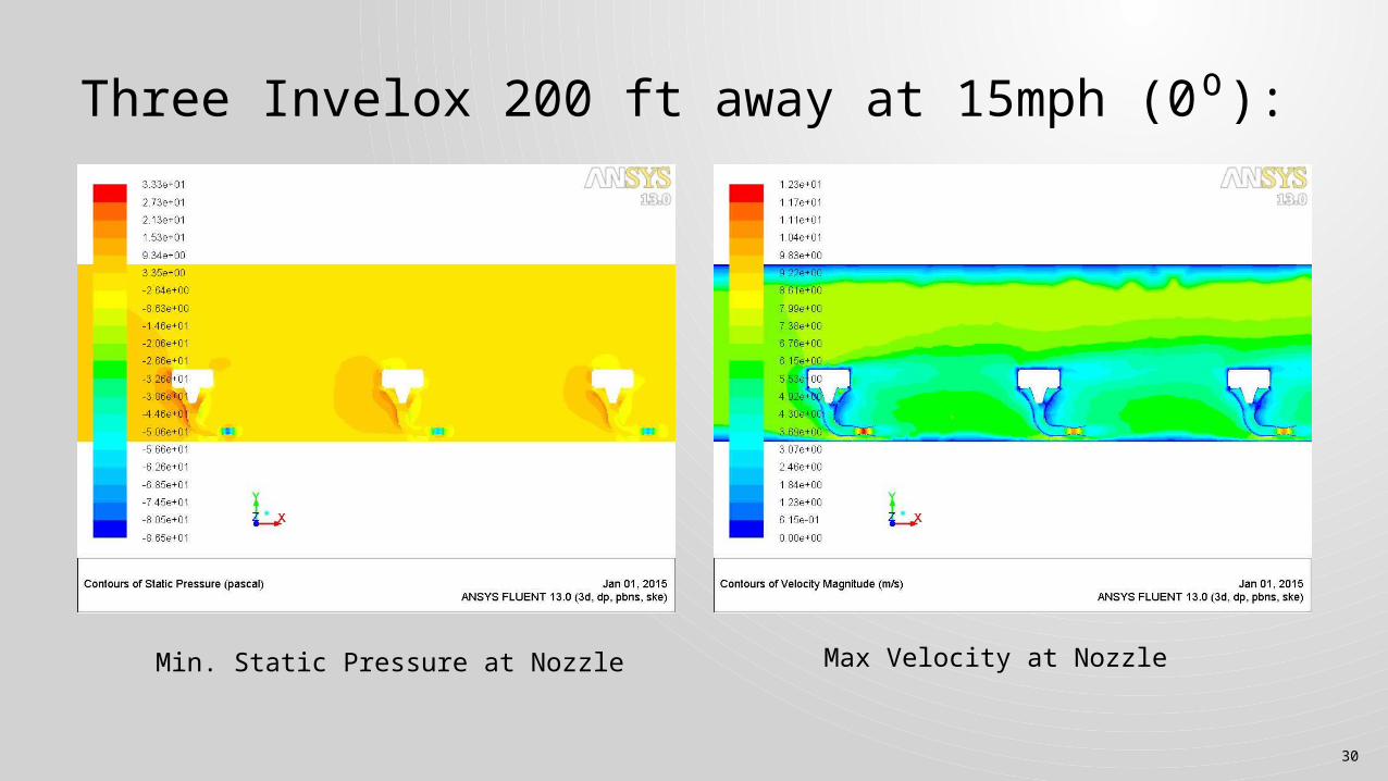
(⁰) (ft) (mph) (m/s) (Pa) (m/s) (Pa) (m/s) (Pa) (m/s)3 0 50 15 6.71 -71 11.30 -44 7.70 -43 7.503 0 75 15 6.71 -78 11.8 -50 8.27 -50 8.273 0 150 15 6.71 -82 11.93 -65 8.95 -65 8.953 0 175 15 6.71 -84 12.11 -68 9.69 -68 9.693 0 200 15 6.71 -86 12.29 -76 11.7 -76 11.73 0 500 15 6.71 -83 12.1 -83 12.1 -83 12.1
Invelox Air Venturi-1(Centerline) Venturi-2(Centerline)Venturi-3(Centerline)
29
Three Invelox 50 ft away at 15mph (0⁰):
Min. Static Pressure at Nozzle Max Velocity at Nozzle
30
Three Invelox 200 ft away at 15mph (0⁰):
Min. Static Pressure at Nozzle Max Velocity at Nozzle
31
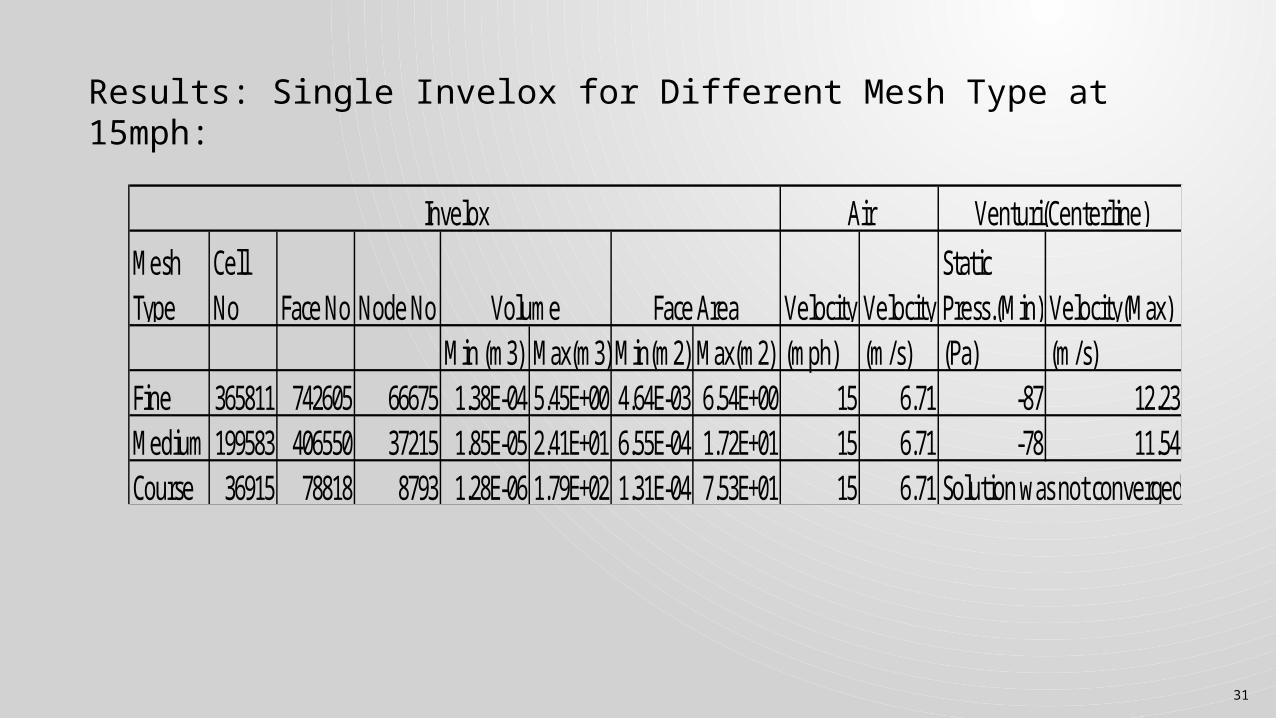
Results: Single Invelox for Different Mesh Type at 15mph:
Mesh Type
Cell No Face No Node No Velocity Velocity
Static Press.(Min) Velocity(Max)
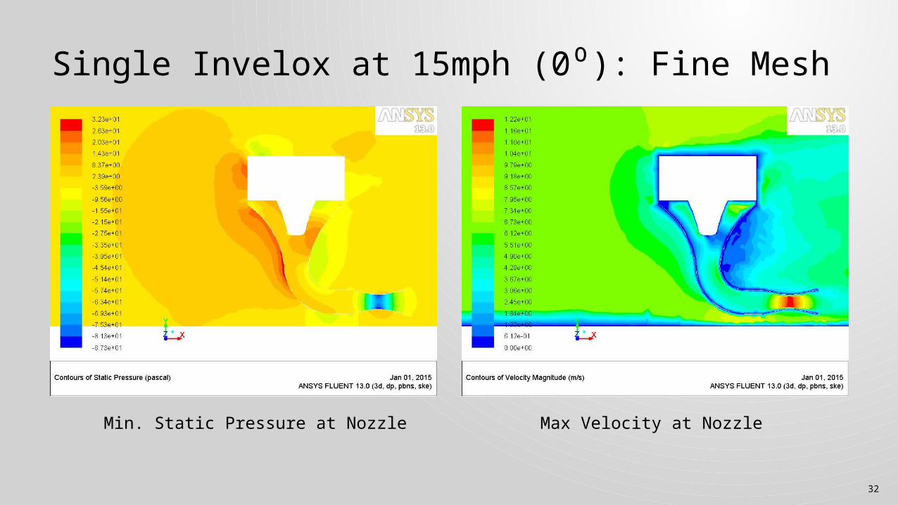
Min (m3) Max(m3) Min(m2) Max(m2) (mph) (m/s) (Pa) (m/s)Fine 365811 742605 66675 1.38E-04 5.45E+00 4.64E-03 6.54E+00 15 6.71 -87 12.23Medium 199583 406550 37215 1.85E-05 2.41E+01 6.55E-04 1.72E+01 15 6.71 -78 11.54Course 36915 78818 8793 1.28E-06 1.79E+02 1.31E-04 7.53E+01 15 6.71 Solution was not converged
Volume Face Area
Invelox Air Venturi(Centerline)
32
Single Invelox at 15mph (0⁰): Fine Mesh
Min. Static Pressure at Nozzle Max Velocity at Nozzle
33
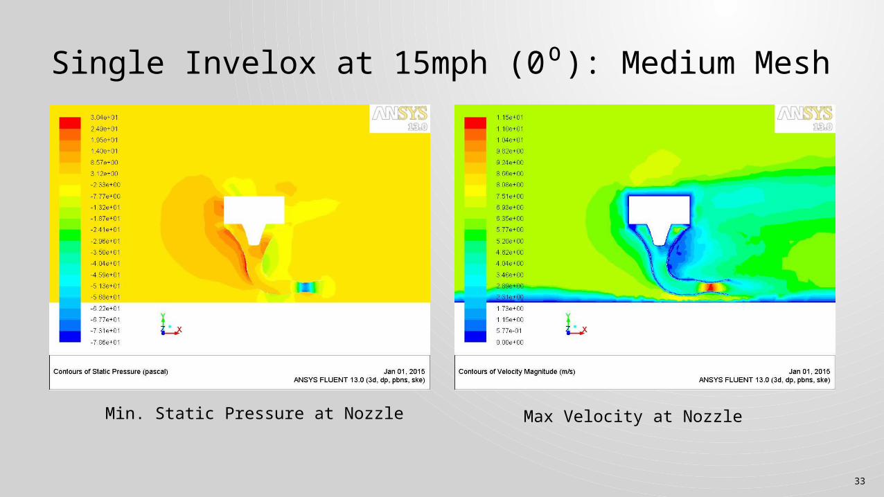
Single Invelox at 15mph (0⁰): Medium Mesh
Min. Static Pressure at Nozzle Max Velocity at Nozzle
34
At higher wind velocity the invelox produce higer venture velocity and lower static pressure which in turn produces high amount of power generation.
The 0⁰ (along with the wind direction) orientation produces higher velocity than 180⁰ and 90⁰ scenarios.
The invelox should be placed at a minimum distance to produce power at highest efficiency. For 0⁰ (along with the wind direction) orientation at 15mph wind speed the Invelox has to be placed at least 250 ft away from each other.
Discussion
35
Prof.Y. Andreapolos, Dr. Daryoush Allaei Invelox “ A New Concept In Wind Energy Harvesting” ES-FuelCell2013-18311
References