prescribed performance control based on pso identi cation
TRANSCRIPT

CEAI, Vol.22, No. 1, pp. 24-31, 2020 Printed in Romania
Prescribed Performance Control Based onPSO Identification and DisturbanceObserver for Automotive Electronic
Throttle System with Actuator Constraint
Zitao Sun, Xiaohong Jiao, Jiaqi Xue
Institute of Electrical Engineering, Yanshan University, Qinhuangdao,066004 China (e-mail: [email protected])
Abstract: To further improve the transient and static performance of the practical automotiveelectric throttle control system against nonlinearity and uncertainty, a prescribed performance-based servo control strategy is investigated in this paper for the electric throttle systemwith actuator constraint. For handling the uncertain system parameters, particle swarmoptimization (PSO) is adopted to identify the nominal physical parameters and disturbanceobserver technique is utilized to estimate the parameter perturbations and load torque.Moreover, for the practicability of prescribed performance control, the actuator constraintis considered in the controller design. Theoretical analysis is given to prove the trackingperformance with the required transient and steady states of the resulting closed-loop system.Meanwhile, the effectiveness and applicability of the proposed control strategy are shownby both Matlab/Simulink simulation and dSPACE-based hardware-in-the-loop experimentalverification.
Keywords: electronic throttle system (ETS), actuator constraint, prescribed performancecontrol, particle swarm optimization (PSO), parameter identification
1. INTRODUCTION
As the core part of the automobile engine control system,the electronic throttle control system plays an importantrole in emissions performance and fuel economy of automo-bile Cook et al., (2006); Li et al., (2018). However, in thepractical electronic throttle system, there exist stronglynonlinear factors including friction, return springs, gearbacklash, and parameter uncertainties caused by incom-plete system physical parameters and device aging. Thesefactors not only significantly increase the difficulty of thecontroller design, but also greatly affect the system con-trol performance. Hereby, continuing efforts to improvetransient and static performance focus on developing theeffective control strategies to restrain the influence of thenonlinearities and uncertainties to fast and accuratelytracking the reference command.
Many advanced control strategies are applied in the au-tomotive electronic throttle control systems to achievefast dynamic response and robust performance againstnonlinearities and uncertainties. Various control methodsbased on the identified system model are proposed, suchas, the compound controls of PID feedback and frictioncompensator adopted in Deur et al., (2004); Pujol et al.,(2015), the feedback linearization control methods used inLoh et al., (2007); Grepl and Lee, (2010), and the finite-time convergence control strategy presented in Li and Jiao,
⋆ This work was supported by the National Natural Science Foun-dation of China (No.61573304) and the Natural Science Foundationof Hebei Province (Grant No.F2017203210).
(2017). Meanwhile, some special control methods dealingwith the uncertainty are adopted, such as, adaptive, neuralnetwork, fuzzy, and sliding mode techniques. Nonlinearadaptive control techniques are utilized to estimate andcompensate all uncertain parameters in Pozo et al., (2009);Bernardo et al., (2010); Jiao et al., (2014); Bai, (2018);Jiao et al., (2018) so as to achieve strong robust trackingcontrol performance. Neural networks are utilized in Yuanet al., (2010a,b) to identify the electronic throttle systemand to design tracking controller. A recurrent neural net-work (RNN) identifier and a fuzzy neural network (FNN)controller are presented in Yuan et al., (2010b), and tworadial basis function (RBF) neural networks are used inthe identifier and the controller in Yuan et al., (2010a).Fuzzy control technique is utilized in Wang and Huang,(2013) to design a fuzzy logic controller. Fuzzy approachare adopted in Sun et al., (2018); Yang et al., (2018) toestablish fuzzy model for the uncertainties of the electronicthrottle, and then optimal robust controller and the in-tegral sliding mode controller based on this fuzzy modelare designed, respectively. Various modified sliding modecontrol (SMC), integral SMC Li et al., (2017); Wang et al,(2018a), and fast nonsingular SMC Wang et al., (2018b),are employed to design the tracking controllers based onthe observers for the uncertainty of electronic throttles.
Nevertheless, for the electronic throttle control systemwith a crucial requirement for the transient and staticperformance, a very fast response time and near zero over-shoot still are needed to ensure the drivability, fuel econ-omy, and emission performance of the vehicle. Fortunately,

Control Engineering and Applied Informatics 25
a particular performance bound technique is presented inBechlioulis and Rovithakis, (2009); Han and Lee, (2013),which can guarantee that the transient performances oferrors converge at the prescribed convergence rate andovershoot. This method has been utilized in many prac-tical applications, such as in servo mechanism Na et al.,(2014), robots Psomopoulou et al., (2015); Wang et al.,(2017), and vessel Zheng and Feroskhan, (2017).
On the other hand, it should be noted that the morestrict control performance is required, the more likely thehigher gains of the designed theoretically control inputappears. While the designed controller is implemented inpractice, this often produces control-signal saturation dueto the physical restriction of the actuator. This saturationproblem will potentially affect the actual control systemresulting in the degradation of the control performanceor even the loss of stability if mishandled. In view of thefact, many control strategies dealing with the input satu-ration have been presented. For example, in view of largehigh-frequency gains of prediction filters in the minimum-variance controllers, two methods, employing frequencyweighting and adaptive scheme iteratively over a finiteduration, are presented in Perez-Arancibia et al., (2010)to eliminate the control input saturation problem. Takingsaturation into account in the backstepping design of con-troller, a smooth function is used in Wen et al., (2011) toapproximate the saturation with a bounded approximationerror, and a Nussbaum function is introduced to compen-sate for the nonlinear term arising from the input satu-ration. In Chen et al., (2011), an auxiliary design systemis introduced into the adaptive tracking control design tocompensate for the effects of input saturation for a class ofuncertain multi-input and multi-output nonlinear systems.This method is incorporated in the controller design forvarious physical systems with the input saturation byZheng and Feroskhan, (2017); Bai, (2018).
In this paper, the contribution is to apply the prescribedperformance control combined with PSO identification andadaptive estimate technique in the actual automobile elec-tronic throttle control system to further improve and guar-antee the robust transient and static performance againstnonlinearity and uncertainty. Meanwhile, the control inputsaturation is dealt with by introducing an auxiliary systemin the theoretical design of the tracking controller. Theremainder of this paper is organized as follows. In Section2, the electronic throttle system and control mission arebriefly introduced. In Section 3, a prescribed performanceservo control strategy is designed for a real electronicthrottle with the control constraint based on the PSOidentification and adaptive estimate of the system physicalparameters. The stability and convergence guaranteeingthe prescribed performance is analyzed for the closed-loop system with the proposed control strategy. The effec-tiveness verification and comparative result are presentedby both simulation and experimental test in Sections 4.Finally, the conclusion is given in Section 5.
2. ELECTRONIC THROTTLE SYSTEM ANDCONTROL MISSION
In this paper, an electronic throttle body used in real carsis selected as the researched object as the same as in Xue et
al., (2018). Its schematic is shown in Fig.1, which includesan accelerator pedal, electronic control unit (ECU) andthrottle body comprised of a DC motor, a reduction gearset, a valve plate, reverse springs, and position sensors.The voltage signals of the accelerator pedal sensor andthe throttle position sensor are dealt with in the ECU.The control signal generating from the ECU renders theforward and reverse rotation of the DC motor by the dutycycle of the pulse width-modulated (PWM) voltage. TheDC motor actuates the throttle valve plate opening by thetransmission force of the reduction gear box, the elasticforce of the reverse spring and the friction force.
ECU PWM M
Accelerator pedal
Pedal position sensor
Throttle body
Gearbox
Throttle plateReturn spring
Throttle
position
sensor
DC motor
Fig. 1. Schematic of an electronic throttle control system.
According to the electrical and mechanical characteristicsof the electronic throttle, the dynamics of the system canbe described as follows:
u = Ldiadt
+Ria +Keωm (1)
Jmωm = Ktia −Bmωm − Tm (2)
Jtω = Tl −Btω − Tsp(θ)− Tf (ω)− TL (3)
where u is the control voltage, ωm is the motor angularvelocity, ia is the armature current, L and R are the induc-tance and resistance of the armature circuit, respectively.Kt,Ke are the torque constant and the electromotive forceconstant of motor, respectively. Jm, Bm and Jt, Bt arethe moment inertia and the viscous damping constants ofthe motor and of the throttle plate, respectively. Tm andTl are the input and the output torque of the gearbox,respectively. θ and ω = θ are the opening angle and theangular velocity of the throttle plate, respectively. TL isthe load torque including the disturbance torque caused bythe effect of air flow force acting on the throttle plate. Tf
is the friction torque, and Tsp is the return-spring torque,which are described as follows:
Tf (ω) = Fcsgn(ω) (4)
Tsp(θ)=TLHsgn(θ−θ0)+Ks(θ−θ0), θmin≤θ≤θmax (5)
where Fc is the coulomb friction coefficient, TLH and Ks
are the spring offset and gain, respectively. θ0 is calledlimp-home (LH). sgn(·) is the sign function. Assume thatthere is no loss during transmission and the backlash isneglected, the gearbox transmission model is Tl = nTm,where n is the gear ratio. Considering the input saturantconstraint −Umin≤u(t)≤Umax, define
u(v(t)) =
Umax if v(t) > Umax
v(t) if − Umin ≤ v(t) ≤ Umax
Umin if v(t) < −Umin
(6)
where Umin and Umax are known constants. u(v(t)) denotesthe plant input subject to saturation type nonlinearity.

26 Control Engineering and Applied Informatics
In addition, since the value of the armature inductanceis small, it can be ignored. For a real electronic throttle,the physical parameters L, R, Ks, TLH , Fc, J , B, Kt,and Ke are generally incomplete and have device aging,meanwhile, there is the unknown air flow force disturbancein load torque TL. The dynamic model of the electronicthrottle is simplified to the second-order system: θ = ω
bω = u(v(t))− a1θ−a2ω+a3−a4sgn(θ−θ0)−a5sgn(ω)−TL +∆(t)
(7)
where ai, (i = 1, · · · , 5), b are parameters related to thenominal physical parameters, defined as follows, and TL
is related to the load disturbance, ∆(t) represents theperturbations of the system parameters. d(t) =∆(t)−TL
can be regarded as an unknown disturbance input.
a1=RKs
nKt, a2=
BR+n2KtKe
nKt, a3=
RKs
nKtθ0, a4=
RTLH
nKt,
a5=RFc
nKt, b=
JR
nKt, TL=
RTL
nKt, J=n2Jm+Jt, B=n2Bm+Bt.
In this paper, the controller is designed based on iden-tification for nominal parameters ai, b and the estimatefor the unknown disturbance input d(t) (Corless and Tu(1998)). Thereafter, for achieving the control objective ofthe throttle angle θ tracking the desired trajectory θr withthe required transient and static tracking performance,the prescribed performance control technique is introducedin the tracking controller design to satisfy the followingcontrol specifications.
(1) The adjustment time is required to be less than 100ms for any operating conditions and reference signalchanges, meanwhile, no overshoot should be presentin the step response, furthermore, the throttle plateshall never hit the mechanical end stroke Bernardo etal., (2010); Jiao et al., (2014).
(2) The average value of the steady-state tracking erroris not larger than 0.11deg Deur et al., (2004).
(3) The tracking error response curve e(t) of the systemis between the upper and lower limits of the set per-formance function ρ(t)=(ρ0−ρ∞)e−λt+ρ∞ with pos-itive constants defined appropriately ρ0, ρ∞, and λ,furthermore, for no overshoot, the transient responsesatisfies 0 < e(t) < ρ(t) if the initial tracking erroris more than 0 and the transient response satisfies−ρ(t)<e(t)<0 if the initial tracking error is less than0, and the steady-state error of the system are notmore than the set parameters ρ∞.
(4) The controller designed should conform to physicalconstraints on control inputs and safety constraints.
3. PRESCRIBED PERFORMANCE SERVOCONTROL STRATEGY
3.1 System Parameter identification
PSO-based closed-loop identification method is adoptedin this paper to identify the system nominal parametersof a real ETS. The schematic diagram of the identificationprocess is shown in Fig.2, where θa and θi are the actualthrottle angle and the throttle angle of the identifiedmodel, respectively. θr is the reference angle that is a
PID actual ET system
performance index
ET system model
PSO
rq
aq
iq
iX
PID
-
+
+-
-+
Fig. 2. Schematic diagram of the parameter identification.
set of signals activating the internal characteristics of theETS. Moreover, the actual ETS is from a hardware-in-the-loop (HIL) platform shown in Fig.3. The PID controllerin the identified model system is the same as that in theactual system, and the proportional, integral, derivativecoefficients are kp = 0.7, ki = 0.7, kd = 0.17, respectively.
DS1006
Controldesk
Regulated power supply
motor driver
Electronic throttle
Fig. 3. HIL test platform of electronic throttle system.
The fitness function in PSO is chosen as the time weightedsquared error integral:
ITSE =∫ tf0
t(θa − θi)2dt.
tf is the whole running time of a set of excitation signals.Xi=[Xi1, · · · , XiD]T is a vector consisting of D=9 param-eters identified L,R,Ks, TLH , Fc, J,B, nKt, nKe, which isregarded as the ith particle in X=(X1, X2, · · · , Xm). m isan appropriate number of particles chosen as a swarm X.Each particle Xi is a potential solution of the optimizationproblem, and the final optimal solution is obtained bythe iterative optimization (Kennedy and Eberhart, (1995);Alfi, (2011)). During iteratively solving process, the indi-vidual extremum Pi=Xk
i |minITSE in the kth itera-tive step, and the global extremum Pg=Pi|minITSE.The particleXk
i in each iterative step is updated accordingto the following update principle:
Xk+1id = Xk
id + V k+1id ,
V k+1id = wV k
id + r1c1(Pkid −Xk
id) + r2c2(Pkgd −Xk
id)(8)
where i = 1, 2, · · · ,m, d = 1, 2, · · · , D, k = 1, 2, · · · , km.Vi1 = [Vi1, Vi2, · · · , ViD]T is the velocity vector of the ithparticle. r1, r2 are random numbers distributing on [0, 1].c1, c2 are non-negative constants called the accelerationfactors, here c1=2.305, c2=0.195 (according to c1+c2=2.5Alfi, (2011); Li and Jiao, (2017)). w is the weighting factor.Considering that a larger w in the early stage of theiteration can expand the search space to improve the globalsearch ability and a smaller w in the late stage can enhancethe local search to improve the convergence speed, thus,in this paper, w is chosen as a variable number:
w = wmin + (wmax − wmin) ∗ (km − k)/km (9)
where choose wmax = 0.9, wmin = 0.4, m = 20, km = 150.

Control Engineering and Applied Informatics 27
Besides, for avoiding the particles into the local optimum,mutation operator is applied to PSO algorithm (Alfi,(2011); Li and Jiao, (2017)). The procedure of PSO-basedparameter identification is described in detail as follows:
i. Initialization step: initialize X0i , V 0
i , and Pi = X0i ,
Pg = Pi|minITSE, i ∈ (1, 2, · · · ,m).
ii. Iteration step: update Xki , V
ki by (8), compute Pi, Pg.
iii. Mutation step: if Pg maintains the same value for5 iterations in the iterative process and the criterionnot within the allowable error ϵ0, here ϵ0 = 10−4, theninitializing randomly the particles Pg with a probability of10% through the roulette selection.
iv. Judgment step: if Pg ≥ ϵ0, then goto step ii, and ifk < km goto step ii.
v. Output step: output the optimal P ∗g = ITSEmin →
[L,R,Ks, TLH , Fc, J, B, nKt, nKe]T .
Accordingly, the fitness value in the identification iterationis shown in Fig.4. The identified parameters are listed inTable 1. It should be mentioned that the ”limping home”angle θ0 can be obtained by measuring the position ofthrottle valve plate in the static state.
Table 1. System parameters identified
Parameters Value Unit
J 0.0018 kgm2
B 0.0056 Nm/rad/snKt 0.5331 Nm/AnKe 0.6420 V/rad/sks 0.0885 Nm/rad
TLH 0.4418 NmFc 0.2111 NmR 1.6057 ΩL 0.0052 H
0 50 100 150iteration
0
5
10
15
20
fitn
ess v
alu
e
Fig. 4. Fitness value in the identification iteration.
Fig. 5. Validation of the parameter identification.
The identification effectiveness is validated in the testplatform of Fig.3. The validation result is shown in Fig.5,which is the comparison between the output of the modelwith the identified parameters and the actual system out-put when imposing the same reference input. It shows thesynchronization of the output of the PSO-based identifica-tion model with the output of the actual system within cer-tain limited error, which means that the identified modelis useful to the model-based controller design.
3.2 Identification-based prescribed performance controller
Based on the PSO identification result, the prescribedperformance control technique is utilized to design a servocontrol strategy for the electronic throttle system.
Accordingly, for the system (7) with the identified param-eters, a prescribed performance servo controller with theestimate of the unknown disturbance input is designed as:
v(t)=bθr+a1θ+a2ω−a3+a4sgn(θ−θ0)+a5sgn(ω)
−d(t)−bα+ξ(t)/φ(t)+k2z+k3(z−η)(10)
according to Corless and Tu (1998) and noting that the
nominal value of d(t) is zero, d(t) is constructed as:b ˙ω=u−a1θ−a2ω+a3−a4sgn(θ−θ0)−a5sgn(ω)+d
d(t)=γb(ω−ω), γ > 0(11)
the virtual control law
α = (φ− k1φ)ξ, z = θr − ω − α (12)
the transformation of error
ξ(t) = e(t)/φ(t), e(t) = θr − θ (13)
φ(t) is a piecewise continuous function defined as thefollowing form, which is related to the tracking error e(t):
φ(t) =
ρ(t), e(t) ≥ 0−ρ(t), e(t) < 0
(14)
and the auxiliary design system used to reduce the satu-ration effect Bai, (2018):
η=
−k4η−|zN(v−u)|+0.5(v−u)2
η2η+(v−u), |η| ≥ ε
0, |η| < ε(15)
where ε is a small positive design parameter. ki, (i =1, · · · , 4) are positive adjustable parameters satisfying
k2 + 0.5k3 > 0, k4 > 0.5(1 + k3), N > 1 (16)
It should be noted that φ(t) exists when the error e(t) isvaried monotonically.
3.3 Stability and convergence analysis
Considering the error transformation (13) and defining
e2(t) = θr − ω, the system (7) can be redescribed asξ =
1
φ(e2 − φξ)
be2 = bθr + (v − u)− v(t) + a1θ + a2ω − a3+a4sgn(θ − θ0) + a5sgn(ω)− d(t)
(17)
Moreover, from (7) and (11), it follows d = d−d = b(ω− ˙ω),
then,˙d=−γd+ d, d exponentially converges to zero with a
ratio determined by γ and the steady-state error dependson d. Accordingly, for the closed-loop system consisting ofthe system (17) and the designed controller (10)-(15), acandidate of the Lyapunov function is chosen as:
V =1
2ξ2 +
b
2z2 +
1
2η2 +
1
2d2 (18)
28 Control Engineering and Applied Informatics
The time derivative of V is calculated as follows:
V =ξ1
φ(z+α−φξ)+z(be2−bα)+ηη+d(−γd+d)
= −k1ξ2−k2z
2−k4η2+z[(v−u)−k3(z−η)]−γd2
−|zN(v−u)| − 1
2(v−u)2+η(v−u)−zd+dd
≤ −k1ξ2−(k2−
1
2)z2−(k4−
1
2)η2−(γ−1
2− 1
2ϵ)d2
−[|zN(v−u)| − z(v−u)]−k3z(z−η)+ϵ
2d2
(19)
where ϵ > 0 is small enough. Nothing that N > 1 and−k3z(z − η) ≤ − 1
2k3z2 + 1
2k3η2, then, (19) satisfies the
following inequality.
V ≤ −k1ξ2−(k2− 0.5 +0.5k3)z
2−(k4−0.5−0.5k3)η2
−(γ− 1
2− 1
2ϵ)d2+
ϵ
2d2
(20)
When choosing the adjustable parameters k1>0, k2>0.5,k3 > 0, k4 > 0.5(1+k3), γ > 0.5+1/(2ϵ), it follows V <
−ρV+0.5ϵd2,∀(ξ, z, η, d). Moreover, ϵ is small enough andfor slow change of the unknown parameter perturbation,the disturbance input d is almost to be zero. Therefore,the closed-loop control system is bounded-input bounded-output stable with the required static performance. Fur-thermore, due to 0 ≤ ξ(t) < 1 resulting from the transfor-mation error ξ(t) = e(t)/φ(t) and the definition of φ(t), itfollows that e(t) can monotonically converges to zero andthe whole response curve of e(t) is limited to 0 ≤ e(t) <ρ(t),∀t ≥ 0 if e(0) > 0 and −ρ(t) < e(t) ≤ 0,∀t ≥ 0 ife(0) < 0, which means that there is no overshoot in themonotonically transient response of e(t).
4. VERIFICATION OF SIMULATION ANDEXPERIMENT TESTS
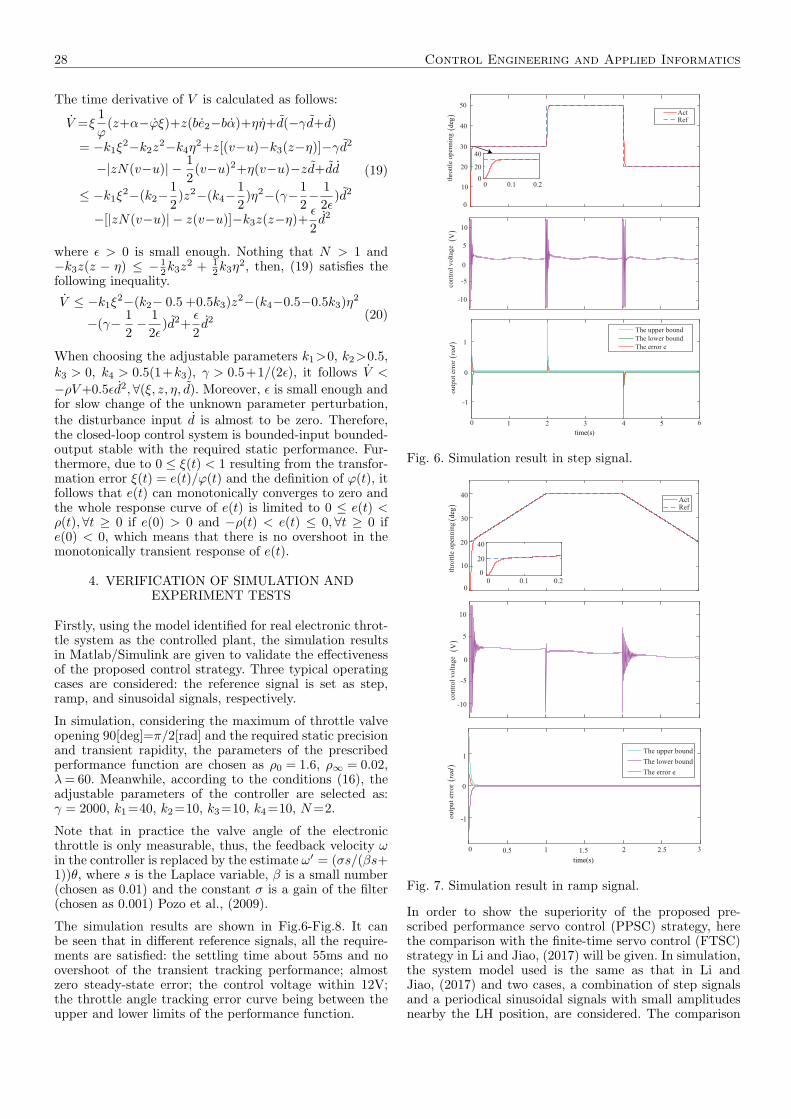
Firstly, using the model identified for real electronic throt-tle system as the controlled plant, the simulation resultsin Matlab/Simulink are given to validate the effectivenessof the proposed control strategy. Three typical operatingcases are considered: the reference signal is set as step,ramp, and sinusoidal signals, respectively.
In simulation, considering the maximum of throttle valveopening 90[deg]=π/2[rad] and the required static precisionand transient rapidity, the parameters of the prescribedperformance function are chosen as ρ0 = 1.6, ρ∞ = 0.02,λ= 60. Meanwhile, according to the conditions (16), theadjustable parameters of the controller are selected as:γ = 2000, k1=40, k2=10, k3=10, k4=10, N=2.
Note that in practice the valve angle of the electronicthrottle is only measurable, thus, the feedback velocity ωin the controller is replaced by the estimate ω′ = (σs/(βs+1))θ, where s is the Laplace variable, β is a small number(chosen as 0.01) and the constant σ is a gain of the filter(chosen as 0.001) Pozo et al., (2009).
The simulation results are shown in Fig.6-Fig.8. It canbe seen that in different reference signals, all the require-ments are satisfied: the settling time about 55ms and noovershoot of the transient tracking performance; almostzero steady-state error; the control voltage within 12V;the throttle angle tracking error curve being between theupper and lower limits of the performance function.
ActRef
The upper bound
The lower bound
The error e
0 1 2 3 4 5 6
-1
0
1
ou
tpu
t er
ror
con
trol
volt
age
-10
-5
0
5
10
thro
ttle
op
enn
ing
0
10
20
30
40
50
20
0 0.1 0.2
40
0
()
deg
()
V(
)rad
time(s)
Fig. 6. Simulation result in step signal.
ActRef
The upper bound
The lower bound
The error e
0 0.5 1 1.5 2 2.5 3
-1
0
1
-10
-5
0
5
10
0
10
20
30
40
0 0.1 0.20
20
40
thro
ttle
op
enn
ing(
)d
egco
ntr
ol
vo
ltag
e(
)V
ou
tpu
t er
ror(
)rad
time(s)
Fig. 7. Simulation result in ramp signal.
In order to show the superiority of the proposed pre-scribed performance servo control (PPSC) strategy, herethe comparison with the finite-time servo control (FTSC)strategy in Li and Jiao, (2017) will be given. In simulation,the system model used is the same as that in Li andJiao, (2017) and two cases, a combination of step signalsand a periodical sinusoidal signals with small amplitudesnearby the LH position, are considered. The comparison

Control Engineering and Applied Informatics 29
ActRef
-10
-5
0
5
10
0
10
20
30
40
con
tro
l v
olt
age(
)V
thro
ttle
op
enn
ing(
)d
eg
0 0.05 0.1 0.015 0.20
20
40
The upper boundThe lower boundThe error e
ou
tpu
t er
ror
(rad
)
time (s)
1.5
1.0
0.5
0
-0.5
-1
-1.5
0 1 2 3 4 5 6 7 8 9 10
2
0
-20 0.05 0.1 0.015 0.2
1 2 3 4 5 6 7 8 9 10
−1
0
1
2x 10
−3
Fig. 8. Simulation result in sinusoidal signal
results are shown in Fig.9 and Fig.10. Obviously, it can beseen from Fig.9 and Fig.10 that both transient and statictracking performance of the proposed PPSC are superiorto that of the FTSC, no overshoot, shorter settling timeand almost zero steady-state error, in especial the trackingerror curves of PPSC in the two cases are between theupper and lower limits of the performance function.
The designed controller is also implemented in the HIL ex-periment platform shown in Fig.3 to verify it applicabilityin practice. Without loss of generality, the two operatingcases are considered:
Case 1. Step signals with large angle variation in very shorttime to validate the fast transient performance, shown inthe dash line of Fig.11.
Case 2. Step signals with a small amplitude change toverify the steady state error overcoming the return springs,shown in the dash line of Fig.12.
Obviously, Fig.11 shows the settling time of the transientresponse about 55ms, both Fig.11 and Fig.12 show thatno overshoot, the steady state error almost zero, and thetracking error curves in the two cases are between theupper and lower limits of the performance function.
In order to further show the superiority of the designedcontroller, HIL experimental comparison with Li and Jiao,(2017) is also given. First select the small angle of repeatedstep change as shown Fig.12 in Li and Jiao, (2017) as theexpected signal, and the comparison result is shown inFig.13. And then, the comparison result under a set ofstair signals is shown in Fig.14. From both experimental
FTSCPPSCRef
10
12
14
16
18
20
22
24
26
thro
ttle
op
enn
ing(
)d
eg
PPSC
FTSC
15
10
5
0
-5
-10
-15
con
tro
l v
olt
age(
)V
The upper bound
The lower bound
The error e
2
1.5
1
0.5
0
-0.5
-1
-1.5
0 1 2 3 4 5 6 7 8
ou
tpu
t er
ror(
)rad
time(s)
Fig. 9. Comparison result in simulation of Case 1
PPSCRefFTSC
0
5
10
15
20
25
thro
ttle
open
nin
g
PPSC
FTSC
15
10
5
0
-5
-10
-15
contr
ol
volt
age
()
deg
()
V
time(s)
The upper boundThe lower boundThe error e
outp
ut
erro
r (r
ad)
2
1.5
1.0
0.5
0
-0.5
-1
-1.50 1 2 3 4 5 6 7 8 9 10
2
0
-20 0.05 0.1 0.015 0.2
1 2 3 4 5 6 7 8 9 10−0.02
−0.01
0
0.01
0.02
Fig. 10. Comparison result in simulation of Case 2
comparisons, it is further verified that the whole errorcurve of the proposed PPSC strategy is limited betweenthe upper and lower limits of the performance function,and has better transient and static tracking response thanthe FTSC of Li and Jiao, (2017)—no overshoot and smallersteady-state error.
5. CONCLUSION
In this paper, a prescribed performance tracking controllerof the throttle valve angle was designed and applied to

30 Control Engineering and Applied Informatics
ActRef
The upper boundThe lower boundThe error e
35
30
25
20
15
10
10
5
0
-5
-10
1.5
1.0
0.5
0
-0.5
-1
-1.5
0 0.05 0.1 0.15 0.2 0.25 0.3 0.35 0.4
thro
ttle
op
enn
ing(
)d
egco
ntr
ol
vo
ltag
e(
)V
ou
tpu
t er
ror(
)rad
time(s)
Fig. 11. Experimental result in Case 1.
ActRef
50
40
30
20
10
10
5
0
-5
-10
1.5
1.0
0.5
0
-0.5
-1
-1.5
0 1 2 3 4 5 6
The upper boundThe lower boundThe error e
thro
ttle
op
enn
ing(
)d
egco
ntr
ol
vo
ltag
e(
)V
ou
tpu
t er
ror(
)rad
time(s)
Fig. 12. Experimental result in Case 2.
a real automotive electronic throttle system. In the con-troller design, the system uncertainty and input satura-tion constraints were considered. The system uncertaintywas handled through PSO identification for the nominalparameters and unknown input-observer-based estimatefor the lumped disturbance including parameter perturba-tions and load torque disturbance. The input saturationwas dealt with the auxiliary system design. Both simu-lation validations and experimental tests showed that the
28
30
32
34
36
thro
ttle
open
ing(d
eg)
−15
−10
−5
0
5
10
15
contr
ol
volt
age(
V) FTSC PPSC
-2
-1
0
1
2 upper bound lower bound error e
0 2 4 6 8 10
the
outp
ut
erro
r (r
ad)
time(s)
REF FTSC PPSC
Fig. 13. Comparison in experiment under repeated steps.
PPSCRefFTSC
45
40
35
30
25
20
15
10
5
0
PPSC
FTSC
15
10
5
0
-5
-10
-15
The upper boundThe lower boundThe error e
2
1.5
1.0
0.5
0
-0.5
-1
-1.5
0 1 2 3 4 5 6 7 8
thro
ttle
open
nin
g(
)d
egco
ntr
ol
volt
age(
)V
outp
ut
erro
r(
)rad
time(s)
Fig. 14. Comparison in experiment under stair signals
utilization of the prescribed performance control techniqueensures the shorter settling time with no overshoot andhigher accuracy of steady state error through limiting thetracking error curve between the upper and lower limits ofthe prescribed performance function.
REFERENCES
Alfi, A. (2011). PSO with adaptive mutation and inertiaweight and its application in parameter estimation ofdynamic systems. ACTA Automatica Sinica, 37(5):541–549.
Bai, R. (2018). Adaptive sliding-mode control of automo-tive electronic throttle in the presence of input satu-

Control Engineering and Applied Informatics 31
ration constraint. IEEE/CAA Journal of AutomaticaSinica, 5(4):878–884.
Bechlioulis, C. P., and Rovithakis, G. A. (2009). Adap-tive control with guaranteed transient and steady statetracking error bounds for strict feedback systems. Auto-matica, 45(2):532–538.
Bernardo, M., Gaeta, A., Montanaro, U., and Santini, S.(2010). Synthesis and experimental validation of thenovel LQ-NEMCSI adaptive strategy on an electronicthrottle valve. IEEE Trans. Control Syst. Technol.,18(6):1325–1337.
Chen, M. M., Sam Ge, S. Z., and Ren, B. (2011). Adaptivetracking control of uncertain MIMO nonlinear systemswith input constraints. Automatica, 47(3):452–465.
Cook, A. J., Sun, J., and Buckland, J. H. (2006). Auto-motive powertrain control-a survey. Asian Journal ofControl, 8(3):237–260.
Corless, M., and Tu, J. (1998). State and input estimationfor a class of uncertain systems. Automatica, 34(6):757–764.
Deur, J., Pavkovic, D., and Peric, N. (2004). An elec-tronic throttle control strategy including compensationof friction and limp-home effects. IEEE Trans. Ind.Applications, 40(3):821–834.
Grepl, R., and Lee, B. (2010). Modeling, parameter es-timation and nonlinear control of automotive electronicthrottle using a rapid-control protoyping technique. Int.Journal of Automotive Technology, 11(4):601–610.
Han, I. S., and Lee, J. M. (2013). Improved prescribedperformance constraint control for a strict feedback non-linear dynamic system. IET Control Theory Applica-tions, 7(14):1818–1827.
Jiao, X., Zhang, J., and Shen, T. (2014). An adaptive servocontrol strategy for automotive electronic throttle andexperimental validation. IEEE Trans. Ind. Electron.,61(11):6275–6284.
Jiao, X., Li, G., and Wang, H. (2018). Adaptive finite timeservo control for automotive electronic throttle withexperimental analysis. Mechatronics, 53(4):192–201.
Kennedy, J., and Eberhart, R. (1995). Particle swarmoptimization. Proceedings of 1995 IEEE InternationalConference on Neural Networks, 1942–1948.
Li, Y., Yang, H., and Yan, B. (2017). Extended stateobserver-based intelligent double integral sliding modecontrol of electronic throttle valve. Adavances in Me-chanical Engineering, 9(12):1–10.
Li, G., and Jiao, X. (2017). Synthesis and validationof finite time servo control with PSO identificationfor automotive electronic throttle. Nonlinear Dynamics,90(2):1165–1177.
Li, Y., Yang, H., and Yang, B. (2018). An extendedcontinuum model incorporating the electronic throttledynamics for traffic flow. Nonlinear Dynamics, 93(4):1923–1931.
Loh, R. N., Pornthanomwong, K. T., and Pyko, J. S.(2007). Modeling, parameters identification, and controlof an electronic throttle control (ETC) system Interna-tional Conference on Intelligent and Advanced Systems,1029–1035.
Na, J., Chen, Q., Ren, X., and Guo, Y. (2014). Adaptiveprescribed performance motion control of servo mech-anisms with friction compensation. IEEE Trans. Ind.Electron., 61(1):486–494.
Perez-Arancibia, N. O., Tsao, T. C., and Gibson, J. S.(2010). Saturation-induced instability and its avoidancein adaptive control of hard disk drives. IEEE Trans.Control Syst. Technol., 18(2):368–382.
Pozo, F., Acho, L., and Vidal, Y. (2009). Nonlinear adap-tive tracking control of an electronic throttle system:Benchmark experiments. IFAC workshop on engine andpowertrain control, simulation and modeling.
Psomopoulou, E., Theodorakopoulos, A., Doulgeri, Z.,and Rovithakis, G. A. (2015). Prescribed performancetracking of a variable stiffness actuated robot. IEEETrans. Control Syst. Technol., 23(5):1914–1926.
Pujol, G., Vidal, Y., Acho, L., and Vargas, A. N. (2015).Asymmetric modelling and control of an electronicthrottle. Int. J. Numerical Modelling Electronic Net-works Devices Fields, 29(2):192–204.
Sun, H., Zhao, H., and Huang, K. (2018). Nonlinearadaptive tracking control of an electronic throttle sys-tem: Benchmark experiments. IEEE Trans. Fuzzy Syst.,26(2):694–704.
Wang, C. H., and Huang, D. Y. (2013). A new intelligentfuzzy controller for nonlinear hysteretic electronic throt-tle in modern intelligent automobiles. IEEE Trans. Ind.Electron., 60(6):2332–2345.
Wang, W., Huang, J., and Wen, C. (2017). Prescribed per-formance bound-based adaptive path-following controlof uncertain nonholonomic mobile robots. Int. J. Adapt.Control Signal Process, 31(5):805–822.
Wang, H., Li, Z., and Jin, X. (2018a). Adaptive integralterminal sliding mode control for automobile electronicthrottle via an uncertainty observer and experimen-tal validation. IEEE Trans. Veh. Technol., 67(9):8129–8143.
Wang, H., Shi, L., and Man, Z. (2018b). Continuous fastnonsingular terminal sliding mode control of automo-tive electronic throttle systems using finite-time exactobserver. IEEE Trans. Ind. Electron., 65(9):7160–7172.
Wen, C., Zhou, J., Liu, Z., and Su, H. (2011). Robustadaptive control of uncertain nonlinear systems in thepresence of input saturation and external disturbance.IEEE Trans. Automat. Control, 56(7):1672–1678.
Xue, J., Jiao, X., Sun, Z. (2018). ESO-based double closedloop servo control for automobile electronic throttle.5th IFAC Conference on Engineand Powertrain Control,Simulation and Modeling, IFAC PapersOnLine, 51-31:979–983.
Yang, B., Liu, M., Kim, H., and Cui, X. (2018). Contin-uous fast nonsingular terminal sliding mode control ofautomotive electronic throttle systems using finite-timeexact observer. Journal of Process Control, 61(1):36–46.
Yuan, X., Wang, Y., Sun, W., and Wu, L. (2010a).RBF networks-based adaptive inverse model controlsystem for electronic throttle. IEEE Trans. ControlSyst. Technol., 18(3):750–756.
Yuan, X., Wang, Y., and Wu, L. (2010b). Neural networkbased self-learning control strategy for electronic throt-tle valve. IEEE Trans. Veh. Technol., 59(8):3757–3765.
Zheng, Z., and Feroskhan, M. (2017). Path following ofa surface vessel with prescribed performance in thepresence of input saturation and external disturbances.IEEE/ASME Trans. Mechatron., 22(6):2564–2575.