pres c6 report - us department of transportation€¦ · non-aashto - does not meet aashto, but is...
TRANSCRIPT
PRES
WIP Report
Federal Highway AdministrationEastern Federal Lands Highway DivisionRoad Inventory Program (RIP)
Prepared By:
NPS Retaining Wall Inventory ProgramPresidio of San Francisco
Data Collection Date: November 2007Report Date: November 2015

inCalifornia
_̂
_̂
_̂
_̂
_̂
_̂
Ely
Bend
Reno
Yuma
Ogden
Butte
Eugene
Fresno
Kingman
Medford
Oakland
Redding
San Jose
Portland
Pocatello
Las Vegas
Flagstaff
San Diego
St. George
Twin Falls
Idaho Falls
Bakersfield
Los Angeles
San Francisco
Boise
Salem
Phoenix
Sacramento
Carson City
Salt Lake City
Sna k e
Gila
Klam ath
Colorado
Kings
Sacramento
Bear
San Joa qu in
Missouri
Sources: Esri, HERE, DeLorme, TomTom, Intermap, increment P Corp., GEBCO, USGS, FAO, NPS, NRCAN, GeoBase, IGN, Kadaster NL, Ordnance Survey, Esri Japan, METI, Esri China (Hong Kong),swisstopo, MapmyIndia, © OpenStreetMap contributors, and the GIS User CommunityEsri, DeLorme, GEBCO, NOAA NGDC, and other contributors ±
Presidio of San Francisco
Presidio of San Francisco

Table of Contents
SECTION PAGE NO.
1. INTRODUCTION 1 - 1
2. PARK RETAINING WALL LOCATION MAPS
3 - 1
4 - 1TIER 2 - ROUTE RETAINING WALL OVERVIEW
5 - 1
Retaining Wall Location Maps
TIER 3 - RETAINING WALL DETAILS
APPENDIX A - SUMMARY OF WIP DEFINITIONS AND ASSESSMENTCATEGORIES
A - 1
3.
4.
5.
6.
TIER 1 - PARK RETAINING WALL OVERVIEW
2 - 1
Presidio of San Francisco
Introduction

Introduction
The Federal Lands Highway Division (FLH) of the Federal Highway Administration (FHWA), in partnership with the National Park Service (NPS), has conducted a retaining wall inventory and condition assessment as part of the NPS Retaining Wall Inventory Program (WIP). This inventory provides information to the NPS Facility Management Software System (FMSS) regarding such things as type, size and location of retaining structures, as well as the condition of these facilities and consequences of failure. In addition, when wall and/or adjacent element deficiencies are identified, repair recommendations and estimated costs are also provided, suitable for use as FMSS work orders.
The main intent of this effort is to determine the backlog of needs associated with retaining wall assets –equipment features ascribed to the “parent” roadway asset. Inventory and condition assessments (pavement only) for the roads themselves are conducted under the NPS Road Inventory Program (RIP). Prior to development of the WIP, the vast majority of retaining walls were not accounted for in FMSS. Based on WIP inventory work to date, NPS wall assets are valued at well over $400M. A second and equally important intent of this effort is to inform and improve project selection, prioritization, and development activities and processes at NPS regions/parks, FLH Division offices and the NPS Denver Service Center.
In support of WIP, a comprehensive procedures manual (available at the following link: http://www.cflhd.gov/programs/techDevelopment/geotech/WIP/) was developed to document the data collection and management process, wall attribute and element definitions, and team member responsibilities for conducting retaining wall inventories and condition assessments. This manual was used for nearly 3,500 wall assessments initially conducted between 2007 and 2008 within 34 national parks. WIP is supported by several key components described in the procedures manual, including a comprehensive training program for field inspectors, an Oracle-based database for long-term data management, unique data collection forms, a supporting field guide, and a wall repair/replace cost estimate guide.
Ultimately, condition assessments for retaining wall structures are expressed as deferred maintenance costs, which are then divided by current year replacement costs to arrive at a “Facility Condition Index” (FCI). Coupling this condition prioritization index with an “Asset Priority Index” (API), which measures the feature’s importance to the mission of the park, capital asset investments are made more efficiently. This approach appropriately focuses maintenance and construction priorities on value, rather than solely on cost. Wall inventory condition and cost data are transferred from the WIP database to FMSS, the primary asset documentation, management and planning platform maintained at each park. In addition, wall data are also provided to the Road Inventory Program to update equipment assets associated with the parent roadway asset.
Initial inventories were conducted based on RIP Cycle 3 data, but future planning has ensured updates to WIP will occur simultaneously with RIP. For long-term data management purposes, the WIP database will be linked to the larger, parent RIP database and be updated under the responsibility of the RIP Database Administrator.
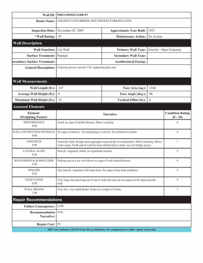
This report is organized in a tiered approach from the broad park overview perspective (Tier 1) to a route overview perspective (Tier 2), then down to the details of each wall (Tier 3). Tier 1 presents park wall location maps and an overall park-specific summary narrative of the results of the wall inventory program. Tier 2 presents route overview maps with associated wall summary information. Tier 3 presents individual wall information in a three-page detailed format, including a photograph of each wall. Appendix A provides a condensed summary of wall inventory definitions and assessment categories to assist in reading this report.

Presidio of San Francisco
Park Retaining Wall Location Maps

WALL LOCATION MAPKey Map
Sources: Esri, HERE, DeLorme, Intermap, increment P Corp., GEBCO, USGS, FAO, NPS, NRCAN, GeoBase, IGN, Kadaster NL, Ordnance Survey, Esri Japan, METI, Esri China (Hong Kong), swisstopo, MapmyIndia, ©OpenStreetMap contributors, and the GIS User Community
Presidio of San Francisco
±0 0.15 0.3
Miles
RIP Collected Routes
Map 1
!(
09600969CZ
0968AZ
0982
0968BZ
0969BZ
0993
0970
0969AZ
0612
0969ZZ-0.000-P1
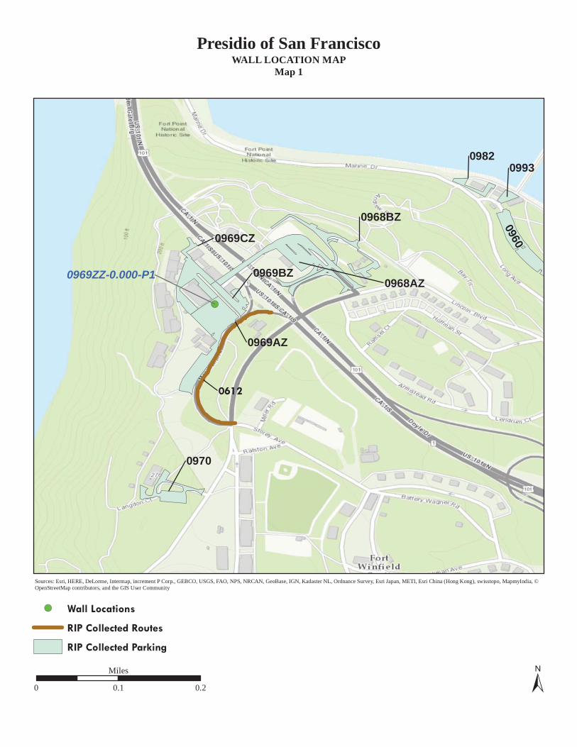
WALL LOCATION MAPMap 1
Sources: Esri, HERE, DeLorme, Intermap, increment P Corp., GEBCO, USGS, FAO, NPS, NRCAN, GeoBase, IGN, Kadaster NL, Ordnance Survey, Esri Japan, METI, Esri China (Hong Kong), swisstopo, MapmyIndia, ©OpenStreetMap contributors, and the GIS User Community
Presidio of San Francisco
±0 0.1 0.2
Miles
!( Wall Locations
RIP Collected Routes
RIP Collected Parking

Presidio of San Francisco
Tier 1Park Retaining Wall Overview
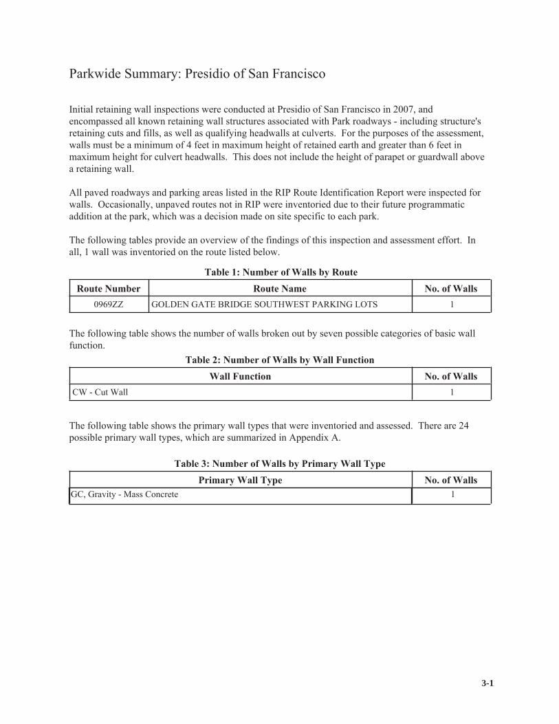
3-1
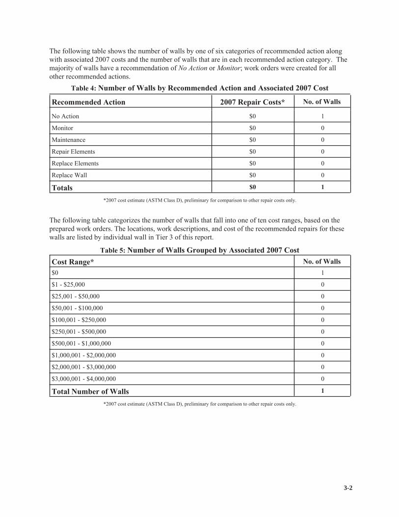
3-2

No critically deficient walls

Presidio of San Francisco
Tier 2Route Retaining Wall Overview
Wall ID Wall Length(Ft.)
Wall Area(Sq. Ft.)
RepairCost
WallType
OverallRating
WallFunction
0969ZZ-0.000-P1
Sources: Esri, HERE, DeLorme, TomTom, Intermap, increment P Corp., GEBCO, USGS, FAO, NPS, NRCAN, GeoBase, IGN, Kadaster NL, Ordnance Survey, Esri Japan, METI, Esri China (Hong Kong), swisstopo,MapmyIndia, © OpenStreetMap contributors, and the GIS User Community
4-1
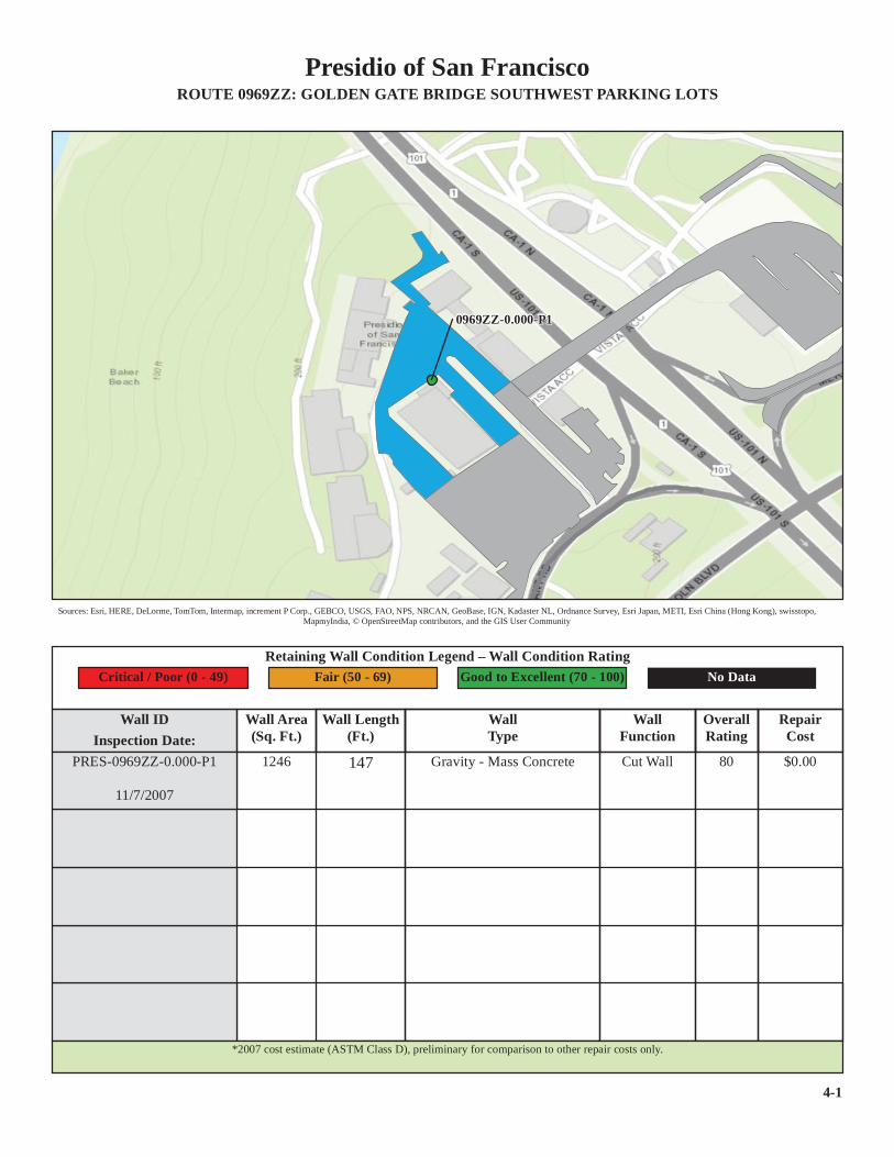
Presidio of San FranciscoROUTE 0969ZZ: GOLDEN GATE BRIDGE SOUTHWEST PARKING LOTS
1246 Cut Wall 80 $0.00Inspection Date:
147
Retaining Wall Condition Legend – Wall Condition RatingFair (50 - 69) Good to Excellent (70 - 100)Critical / Poor (0 - 49) No Data
PRES-0969ZZ-0.000-P1
11/7/2007
Gravity - Mass Concrete
*2007 cost estimate (ASTM Class D), preliminary for comparison to other repair costs only.

Presidio of San Francisco
Tier 3Retaining Wall Details
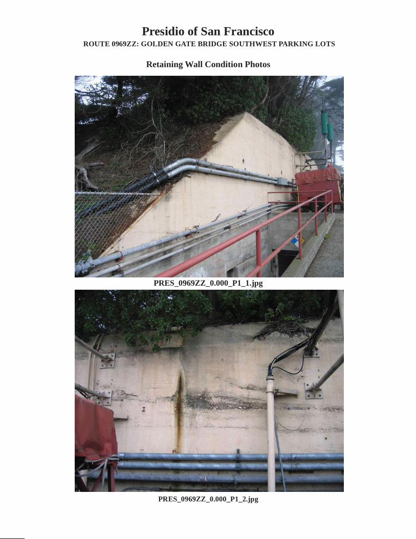
Presidio of San FranciscoROUTE 0969ZZ: GOLDEN GATE BRIDGE SOUTHWEST PARKING LOTS
Retaining Wall Condition Photos
PRES_0969ZZ_0.000_P1_1.jpg
PRES_0969ZZ_0.000_P1_2.jpg

Presidio of San Francisco
Appendix ASummary of WIP Definitions

Appendix A
Summary of WIP Definitions and Assessment Categories

Wall Naming Convention
Unique “Wall Identification” names were assigned to the retaining walls that were inventoried. The Wall Identification includes the Park Name, the RIP Route Number (e.g., 0013), the beginning milepoint of a wall (e.g., 0.622) and the side of the road the wall is located on (e.g., L.) relative to the primary direction of travel (direction of increasing mileposts). Thus, a typical wall identified would have the following format: YOSE-0013-0.622-L.
For roadways not in RIP, park-supplied route numbers were used or the convention RRR#. Similarly, for parking areas not in RIP, the park-supplied parking area number or the convention PPP# was used. Also for parking areas, walls are numbered in ascending order as they are encountered when traveling counterclockwise around the parking area (most common direction of traffic flow). Parking area walls are designated P1, P2, P3, etc. as new walls are encountered.
A-1

Design Criteria
Consequence of Failure
Action
Weighting Factor
Data Reliability
[BW] Bridge Wall [SW] Switchback Wall[HW] Head Wall [SP] Slope Protection [FL] Flood Wall
[CC] Crib, Concrete [MG] MSE, Geosynthetic Wrapped Face
[CM] Crib, Metal [MP] MSE, Precast Panel[CT] Crib, Timber [MS] MSE, Segmental Block[GB] Gravity, Concrete Block/ Brick [MW] MSE, Welded Wire Face[GC] Gravity, Mass Concrete [SN] Soil Nail[GD] Gravity, Dry Stone [TP] Tangent/ Secant Pile[GG] Gravity, Gabion [OT] Other, User Defined[GM] Gravity, Mortared Stone [NO] None
[PF] Planted Face [SS] Simulated Stone
[SC] Sculpted Shotcrete [SV] Stone Veneer[SH] Shotcrete (nozzle finish) [TI] Timber[SM] Steel/Metal [OT] Other, User Defined
[SO] Stone [NO] None
[PS] Preservative [WS] Weathering Steel
[SE] Silane Sealer [OT] Other, User Defined[ST] Stain [NO] None[TR] Tar Coated
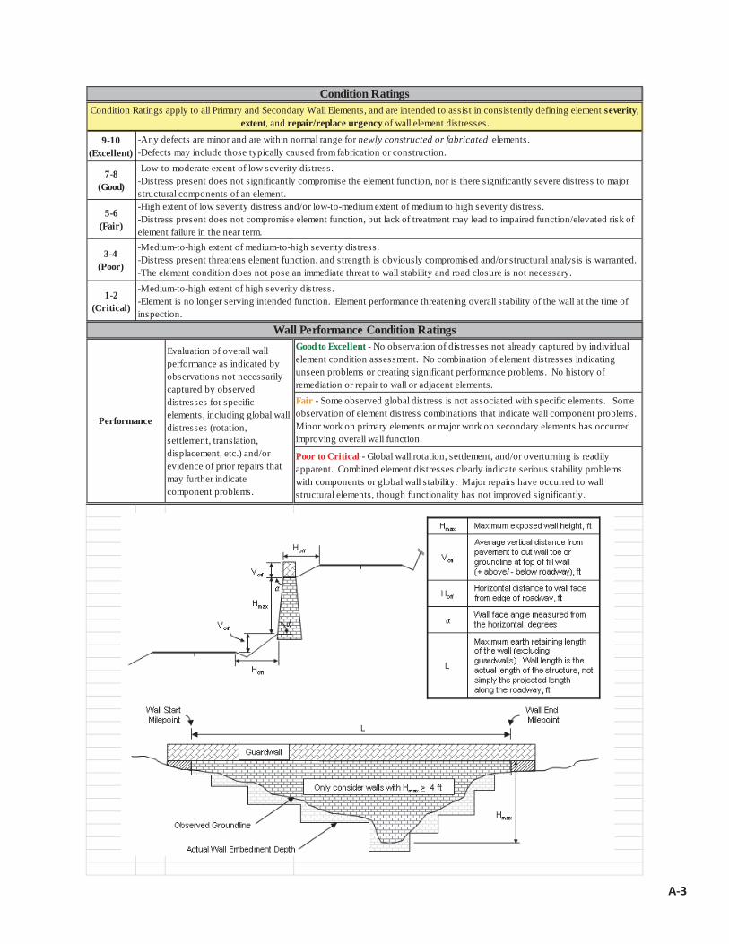
*All classes of paved roadways and parking areas included in the RIP Route Investigation Report and/or identified by park staff. *Walls must reside within the constructed roadway/parking area prism. *Maximum wall height, including only that portion actively retaining soil and/or rock, must be 4 ft. (>6ft for culvert headwalls).
*Consider known/verifiable wall embedment in determining maximum retaining wall height. Include fully buried retaining structures. *Walls have an internal wall face angle *Include all walls where the intent is to support/protect the travelway, and where failure would require replacement with a retaining wall.
- NPS Retaining Wall Inventory Program Field Guide (WIFG)-Retaining Wall Acceptance Criteria
Definitions
Estimate of how well observed conditions represent wall performance, and if additional investigations may be warranted. 1-Poor Conditions cannot be sufficiently observed to rate element(s), warranting additional investigations to better define element performance and/or to determine the cause(s) or poor performance. 2-Good Observed conditions are sufficient to rate the conditions of wall element(s); however, additional investigations would be useful to better understand element performance. 3-Very Good Observed conditions clearly describe wall performance. Additional investigations are not needed.
Measure of how well current design criteria are satisfied:None - Does not meet any known standards. Non-AASHTO - Does not meet AASHTO, but is consistent with other structures of its type/period with good performance. AASHTO - Apparently meets current AASHTO Geometric, Design, Materials, and Construction Standards.
Weighting Factor to be applied to the Condition Rating (CR). When indicated on the Condition Assessment Input Form: WF=0.5 for CR=8-10; WF=1.0 for CR=4-7; and WF=5 for CR=1-3.
Low - No loss of roadway, no to low public risk, no impact to traffic during wall repair/replacement Moderate- Hourly to short-term closure of roadway, low-to-moderate public risk, multiple alternate routes available High- Seasonal to long-term loss of roadway, substantial loss-of-life risk, no alternate routes available
Select from: No Action, Monitor, Maintenance, Repair Elements, Replace Elements, and Replace Wall
Wall Function Codes[FW] Fill Wall[CW] Cut Wall
Wall Type Codes[AH] Anchor, Tieback H-Pile[AM] Anchor, Micropile
[CP] Cantilever, Soldier Pile
[CS] Cantilever, Sheet Pile
Architectural Facing Type Codes[BV] Brick Veneer
[AS] Anchor, Tieback Sheet Pile[BC] Bin, Concrete[BM] Bin, Metal[CL] Cantilever, Concrete
[PA] Painted
Surface Treatment Codes[BG] Bush Gun (tool-textured concrete)[CA] Color Additive[GL] Galvanized
[CO] Cementitious Overlay[FF] Fractured Fin Concrete[FL] Formlined Concrete[PC] Plain Concrete (float finish or light texture)
A-2
9-10 (Excellent)
7-8 (Good)
5-6 (Fair)
3-4 (Poor)
1-2 (Critical)
Good to Excellent - No observation of distresses not already captured by individual element condition assessment. No combination of element distresses indicating unseen problems or creating significant performance problems. No history of remediation or repair to wall or adjacent elements.Fair - Some observed global distress is not associated with specific elements. Some observation of element distress combinations that indicate wall component problems. Minor work on primary elements or major work on secondary elements has occurred improving overall wall function.
Poor to Critical - Global wall rotation, settlement, and/or overturning is readily apparent. Combined element distresses clearly indicate serious stability problems with components or global wall stability. Major repairs have occurred to wall structural elements, though functionality has not improved significantly.
Performance
-High extent of low severity distress and/or low-to-medium extent of medium to high severity distress. -Distress present does not compromise element function, but lack of treatment may lead to impaired function/elevated risk of element failure in the near term. -Medium-to-high extent of medium-to-high severity distress. -Distress present threatens element function, and strength is obviously compromised and/or structural analysis is warranted. -The element condition does not pose an immediate threat to wall stability and road closure is not necessary.-Medium-to-high extent of high severity distress. -Element is no longer serving intended function. Element performance threatening overall stability of the wall at the time of inspection.
Condition RatingsCondition Ratings apply to all Primary and Secondary Wall Elements, and are intended to assist in consistently defining element severity,
extent, and repair/replace urgency of wall element distresses.
-Any defects are minor and are within normal range for newly constructed or fabricated elements. -Defects may include those typically caused from fabrication or construction. -Low-to-moderate extent of low severity distress. -Distress present does not significantly compromise the element function, nor is there significantly severe distress to major structural components of an element.
Wall Performance Condition Ratings
Evaluation of overall wall performance as indicated by observations not necessarily captured by observed distresses for specific elements, including global wall distresses (rotation, settlement, translation, displacement, etc.) and/or evidence of prior repairs that may further indicate component problems.
A-3