preprint - university of adelaide
TRANSCRIPT
SUBMITTED VERSION
Sarabjeet Singh, Carl Q.Howard, Colin H.Hansen An extensive review of vibration modelling of rolling element bearings with localised and extended defects Journal of Sound and Vibration, 2015; 357:300-330 © 2015 Elsevier Ltd. All rights reserved.
Published version available at:
http://dx.doi.org/10.1016/j.jsv.2015.04.037
http://hdl.handle.net/2440/94288
PERMISSIONS
http://www.elsevier.com/about/company-information/policies/sharing#preprint
Preprint
• Authors can share their preprint anywhere at any time. • If accepted for publication, we encourage authors to link from the preprint to
their formal publication via its Digital Object Identifier (DOI). Millions of researchers have access to the formal publications on ScienceDirect, and so links will help your users to find, access, cite, and use the best available version.
• Authors can update their preprints on arXiv or RePEc with their accepted manuscript .
Please note:
• Cell Press, The Lancet, and some society-owned titles have different preprint policies. Information on these is available on the journal homepage.
• Preprints should not be added to or enhanced in any way in order to appear more like, or to substitute for, the final versions of articles.
10 September 2015

An extensive review of vibration modelling of rolling element bearings with
localised and extended defects
Sarabjeet Singh1,∗, Carl Q. Howard, Colin H. Hansen
School of Mechanical Engineering, The University of Adelaide, Adelaide, South Australia 5005, Australia
Abstract
This paper presents a review of literature concerned with the vibration modelling of rolling element bear-ings that have localised and extended defects. An overview is provided of contact fatigue, which initiatessubsurface and surface fatigue spalling, and subsequently leads to reducing the useful life of rolling elementbearings. A review is described of the development of all analytical and finite element (FE) models availablein the literature for predicting the vibration response of rolling element bearings with localised and extendeddefects. Low- and high-frequency vibration signals are generated at the entry and exit of the rolling ele-ments into and out of a bearing defect, respectively. The development of this finding is described alongwith analytical models to approximate these vibration signals. Algorithms to estimate the size of bearingdefects are reviewed and their limitations are discussed. A summary of the literature is presented followedby recommendations for future research.
Keywords:rolling element bearing, localized defect, extended defect, vibration, spall, contact fatigue
1. Introduction1
Rolling element bearings, also referred to as anti-friction bearings [1], are widely used in rotating ma-2
chinery across various industries that include aerospace, construction, mining, steel, paper, textile, railways,3
and renewable energy [2]. The damage and failure of bearings contribute to machinery breakdown, conse-4
quently causing significant economic losses and even loss of human lives in certain situations; for example,5
when an aircraft engine fails or a train derails due to a bearing seizure. Undesirable vibrations in rolling6
element bearings can be caused by either faulty installation, poor maintenance and handling practices [3]7
or surface fatigue [4], which eventually leads to the formation of various types of defects [5], often referred8
to as spalls, within rolling element bearings. It is well-known that when a defective (spalled) component,9
either a rolling element, an outer raceway or inner raceway, within an operating bearing interacts with its10
corresponding mating components, either defective or non-defective, abrupt changes in the contact stresses11
occur [6]. These changes excite the bearing structure and encompassing structural components connected12
to the bearing, resulting in the generation of vibrations, and consequently acoustic signals, which can be13
monitored to detect the presence of a defect using appropriate condition-based (vibration and acoustic)14
diagnostic techniques [3, 6–18].15
Since the early 1950s, numerous researchers have contributed, experimentally and analytically, with the16
ultimate objective to understand the vibration response of non-defective (ideal) [19–42] and defective rolling17
∗Corresponding Author. Tel.: +61 8 8362 5445; fax.: +61 8 8362 0793Email addresses: [email protected] (Sarabjeet Singh), [email protected] (Carl Q. Howard),
[email protected] (Colin H. Hansen)1Present Address: Trackside Intelligence Pty Ltd, 17–19 King William Street, Kent Town, South Australia 5067, Australia
Preprint submitted to Journal of Sound and Vibration April 6, 2015

element bearings [43–119]. Defects in rolling element bearings can be classified into three broad categories —18
localised [43–79], extended defects [68, 80], and distributed [81–119]. This paper presents a review of the19
first two.20
This paper begins with a discussion of contact fatigue in rolling element bearings along with an overview21
of some typical bearing defects in Section 1.1. A review of the existing knowledge pertinent to the vibration22
response of rolling element bearings having localised defects obtained through experimental work [3, 76, 79,23
120–124], a number of analytical [43–69], and FE models [70–79] is presented in Section 2. The vibration24
modelling of bearings having extended defects [68, 80] is discussed in Section 3. The characteristics of25
vibration signatures at the entry and exit of rolling elements into and out of a localised bearing defect26
[76, 77, 79, 120–124], respectively, along with the physics behind the generation of defect-related vibration27
impulses [76, 79] are discussed in Section 4. This is followed by a discussion on the estimation of an average28
size of a bearing defect [67, 76, 79, 124, 125] in Section 5. The existing knowledge is summarised in Section 629
followed by some future directions in Section 7.30
1.1. Contact fatigue31
Contact fatigue is a type of a surface defect or damage [126–128] that is inevitably related to the32
operational wear of rolling element bearings. It is generally characterised by spalling, pitting, or flaking33
off the metallic particles from the rolling surfaces of a bearing, namely outer raceway, inner raceway, and34
rolling elements [3–5, 129–132]. In the context of bearings, contact fatigue is also referred to as rolling35
contact fatigue because of the rolling and relative sliding movements of the rolling surfaces [130–132].36
Loads acting between the rolling elements and raceways within a bearing develop only small areas of37
contact [133]; the geometry of the contact area and corresponding parameters, such as contact force, stiffness,38
and deformation, follow the classical Hertz theory of elasticity [134–136]. As a result, the elemental loading39
may only be moderate; however, the compressive stresses induced on the rolling surfaces of a bearing are40
extremely high — typically of the order of a few giga-pascals (≈ 2–4GPa) [132, 133].41
It is considered that if a rolling element bearing in service is properly installed, aligned, loaded, lubricated,42
and kept free from contaminants, then the main mode of its failure is surface fatigue, which would result43
after an estimated number of rolling cycles (usually of the order of millions) [132, 133, 137, 138]. This44
(bearing) failure mode is also known as fatigue spalling or pitting, and is characterised by surface spalls or45
pits [3–5, 129–132].46
1.1.1. Fatigue spalling47
In a properly installed and lubricated bearing, the onset of micro-scale subsurface fatigue cracks com-48
mences below the highly stressed rolling surfaces. These cracks typically occur at micro-structural disconti-49
nuities, such as inclusions, inhomogeneity, or carbide clusters, as a result of micro-plastic deformation in the50
region of maximum stresses [139–149]. Due to the continuous and repetitive load (stress) cycles during the51
operation of a bearing, the micro-scale subsurface fatigue cracks continue to progress towards the surface,52
eventually causing the material to break loose or flake off, leading to the formation of macro-scale surface53
spalls or pits [3–5, 129–133]. Although spalls and pits are indiscriminately used in the literature to refer54
to the surface defects within rolling element bearings, Littman [4, 5] distinguished between the micro-scale55
subsurface and macro-scale surface originated fatigue cracks as spalls and pits, respectively [129].56
Figure 1 shows a number of examples of fatigue spalling on various components of rolling element57
bearings: a few point spalls on the rollers are shown in Figure 1a, an area spall on the inner raceway is58
shown in Figure 1b, and area spalls of different characteristic shapes and sizes on the outer raceway are59
shown in Figures 1c and 1d.60
In addition to the fatigue spalling, there are a number of other modes of bearing failure [151]. These61
failure modes include wear due to foreign material, smearing, etching–corrosion, brinelling, and burns from62
electric current discharge [3, 152]. Generally, these damages are caused by a variety of factors that include63
poor maintenance practices, mishandling, incorrect installation, misalignment, and inadequate lubrication.64
Often a bearing may commence to fail in one particular mode which then leads on to other failure modes65
[3]. These damages can cause premature surface fatigue, which eventually reduces the life of rolling element66
bearings.67
2

(a) A few point spalls on the rolling elements. (b) An area spall on the inner raceway.
(c) An area spall on the outer raceway. (d) An area spall on the outer raceway.
Figure 1: Fatigue spalls on various elements of rolling element bearings (courtesy: The Timken Company[150]; permissions to be obtained).
1.1.2. Rolling element bearing life68
Understanding the cause for the onset of surface fatigue cracks is of significant interest not only to69
researchers, but also to bearing manufacturers as it has, historically, been considered to be a limiting factor70
for the useful life of rolling element bearings [153]. As a result, rolling contact fatigue mechanisms in71
bearings leading to their life estimation have been investigated by several researchers [154–191]. In the72
literature, these models are divided into two categories [132] — probabilistic engineering models [154–179]73
and deterministic research models [180–191]. In general, the engineering models are empirical in nature;74
they attempt to predict fatigue lives using solutions of the elastic stress field with the scatter in life being75
incorporated directly using the Weibull probability distribution function [192–194]. In contrast, the research76
models are mechanistic in nature; they assume an initial crack (either surface or subsurface) of a given length77
and orientation, and use fracture mechanics [126–128] to predict the shape of the spall and fatigue life of78
the contact.79
The Lundberg–Palmgren model80
In 1924, Palmgren [137] published a paper outlining his approach to bearing life prediction and an81
empirical formula based upon the concept of an L10 life, or the time that 90% of a bearing population would82
equal or exceed without a fatigue failure. Later on, in 1947, Palmgren along with Lundberg, incorporated83
his previous work [137] with the work of Weibull [192] to present the pioneering mathematical formulation84
for calculating the fatigue life of rolling element bearings [154, 155]. Their theory is commonly known as85
the Lundberg–Palmgren theory. It states that for bearing rings subjected to N cycles of repeated (stress)86
loading, the probability of survival S is given by87
3
ln1
S= A
Neτ c0V
zh0(1)
where, τ0 is the maximum orthogonal shear stress in the contact, z0 is the corresponding depth at which this88
stress occurs, and V is the stressed volume of material. The parameters A, c, and h are material character-89
istics that are determined experimentally, and the parameter e is the Weibull slope for the experimental life90
data plotted on a Weibull probability paper.91
Since the development of the Lundberg–Palmgren theory, significant advances have been made in bearing92
material quality, fracture mechanics, and in the understanding of the role of lubrication through the devel-93
opment of elasto-hydrodynamic lubrication (EHL) theory [131, 195–201], in order to increase the fatigue life94
of rolling element bearings. The recognition of the limitations of the original Lundberg–Palmgren theory95
[154, 155] has led to the development of better and improved bearing fatigue life prediction models. The96
current ISO (International Organization for Standardization) [170], ANSI (American National Standards97
Institute, Inc., and ABMA (American Bearing Manufacturers Association, Inc.) [202, 203] standards for98
rolling bearing life are based on modifications of the Lundberg–Palmgren equation [154, 155]; the modifi-99
cations account for the significant changes in relatively recent material quality, reliability, and operating100
conditions. Excellent reviews of the bearing life models can be found in references [132, 171, 177, 204].101
The following sections present a review of all analytical [43–69] and FE models [70–79] available in the102
literature for predicting the vibration response of defective rolling element bearings having localised and103
extended defects.104
2. Localised defects105
Localised defects, one of the two main classes of bearing defects, include cracks, pits, and spalls on various106
components of a rolling element bearing. The components within a bearing refer to its rolling surfaces —107
outer raceway, inner raceway, and rolling elements. The localised defects are an ultimate failure mode of108
a correctly installed and lubricated bearing during its normal operational use. A few examples of surface109
fatigue spall, localised defects, are shown in Figure 1.110
In order to present a systematic review of analytical and FE models that predict the vibration response111
of rolling element bearings that have localised defects, the models are classified into four broad categories112
as follows:113
1. Periodic impulse-train models [43–46]114
2. Quasi-periodic impulse-train models [47–52]115
3. Nonlinear multi-body dynamic models [53–69]116
4. FE models [70–79]117
2.1. Periodic impulse-train models118
A periodic impulse-train model refers to an analytical model that simulates the generation of defect-119
induced impulses at a constant period. Such a model does not include the physical parameters of a bearing,120
such as masses of bearing components, nor attempts to simulate the deformation at the rolling element-to-121
raceway contact interfaces that is governed by the Hertzian contact theory of elasticity [134–136]. For the122
case of a stationary outer raceway defect, the impulses are equally spaced, and their characteristics, such as123
shape, amplitude, and width, are similar to each other. On the contrary, for a rotating inner raceway defect124
and a rolling element defect, the impulses are generally modulated as per the static load distribution within125
a rolling element bearing; that is, the amplitude of the defect-induced impulses varies as the inner raceway126
and rolling element defects rotate in and out of the bearing load zone [2, 205–208].127
The first model for simulating the vibration response of a localised single point defect on the inner race128
of a rolling element (ball) bearing, under a constant radial load, was developed by McFadden et al. [43] in129
4

1984. The forces produced by the point defect were modelled as an infinite series of periodic force impulses130
of equal amplitude using the Dirac delta function [209, pages 9–10] with a period T as131
I (t) =∞∑
i=−∞
δ (t− iT ) (2)
where, I (t) is the impulse force, δ is the Dirac delta function, t is the time vector, and T is time period of132
the defect-related impulses. The resonance characteristic in the Fourier domain [210] was sampled at the133
regular interval of 1/T . Based on the assumption that the amplitude of the impulse produced by a defect is134
directly proportional to the load on a rolling element when it strikes a defect, the amplitude of the impulses135
was multiplied by the actual load on the rolling elements, estimated using the well-known Stribeck equation136
[205].137
McFadden et al . further extended their defect-induced impulse-train model [43] to incorporate two point138
defects located on the inner race of a ball bearing [44]. The effects of two point defects were simulated by139
treating the defects as the sum of a number of localised defects at different angular locations around the inner140
raceway. Both models [43, 44] incorporated the effects of bearing geometry, shaft rotational speed, bearing141
load distribution, and the exponential decay of vibration. Satisfactory validation of both models was reported142
on the basis of agreement of the predicted vibration (line) spectra with experimental results after conducting143
a standard envelope analysis [211, 212]. While McFadden et al . did not predict the absolute amplitude of144
the defect-related frequency components, fundamental and harmonics, in their first model [43], the predicted145
amplitudes in their second model [44] were corrected based on their experimental results. They found that146
the demodulated (also known as envelope) vibration spectrum was composed of groups of discrete frequency147
components, separated by the shaft rotational frequency fs, while the spacing between the successive groups148
was the inner raceway defect frequency fbpi (also known as ball pass frequency inner raceway — BPFI;149
refer to Appendix A for the definition of BPFI and other defect frequencies associated with rolling element150
bearings). The aforementioned models provided some early insights into the demodulated vibration spectrum151
of a rolling element bearing obtained through accelerometer measurements in practice, and partially helped152
explain the defect-related frequency components, fundamental, sidebands, and associated harmonics, in a153
measured vibration spectrum. The models developed by McFadden et al. [43, 44] are often referred to as154
classical or traditional models in the literature.155
Su et al. [45] extended the models developed by McFadden et al . [43, 44] to predict the vibration156
frequencies produced by a single point defect and multiple (two) point defects within a rolling element157
bearing subjected to various types of loads. They proposed periodicities that include fundamental defect158
frequencies, sidebands and associated harmonics, for the outer raceway, inner raceway, and rolling element159
defects due to various load conditions. These load conditions include shaft unbalance and roller errors,160
in addition to the case of stationary loading along the circumference of the inner race as considered by161
McFadden et al. [43, 44]. Su et al. [45] reported that for a fixed outer raceway defect, the vibration signature162
of a bearing has periodicities at 1/fs and 1/fc due to shaft unbalance and roller errors, respectively, where,163
fs is the shaft rotational frequency, and fc is the cage rotational frequency. However, for an inner raceway164
defect, the vibration response of a bearing has no periodicity due to shaft unbalance, but a periodicity of165
1/(fs − fc) due to roller errors. The comparison of the predicted defect-related frequencies and sidebands166
with the experimental results showed good agreement. The effect of the loading distributions due to shaft167
unbalance and roller errors provided further explanation of the spectral content of the demodulated vibration168
spectrum of a bearing for cases in addition to the cases considered by McFadden et al. [43, 44].169
In the late 1990s, Tandon et al. [46] proposed an analytical model for predicting the vibration frequen-170
cies, fundamental and harmonics, of a rolling element bearing along with the amplitudes of the frequency171
components, caused by a localised single point defect on the outer raceway, inner raceway, and one of the172
rolling elements, under radial and axial loads. Similar to previous models [43–45], Tandon et al. [46] also173
modelled the vibration response using periodic impulse-trains; however, they considered three different types174
of typical pulse shapes of finite width — rectangular, triangular, and half-sine. The results showed that for175
an outer raceway defect, a vibration response is generated at the outer raceway defect frequency fbpo and176
its multiples. For an inner raceway defect, a response is generated at the inner raceway defect frequency177
5
fbpi in the absence of a radial load; however, in its presence, a response is also generated at equi-spaced178
sidebands at the shaft rotational frequency fs in addition to the inner raceway defect frequency fbpi. Tan-179
don et al. [46] also reported that the vibration amplitude due to the outer raceway defect was higher180
compared to that of the inner raceway defect, and the amplitudes of the vibration frequencies and their181
harmonics were affected by the different pulse shapes. Although a fair agreement between the predicted and182
experimental results was claimed, the comparison was only illustrated for the defect on the inner raceway183
of a bearing. Tandon et al. [46] also mentioned that the amplitudes of the predicted frequency components184
were normalised (or corrected) for the comparison with the experimental results; however, the normalisation185
factor was not discussed. The problem of amplitude mismatch has also been highlighted by several other186
authors [56, 57, 62–64] who, later on, developed nonlinear multi-body dynamic models. These models will187
be discussed in Section 2.3.188
2.2. Quasi-periodic impulse-train models189
A quasi-periodic or an aperiodic impulse-train model refers to an analytical model that includes some190
random fluctuations due to the slip between the rolling elements and the raceways within a bearing [48, 49].191
These quasi-periodic impulse-train models are also referred to as stochastic models.192
The periodic impulse-train models [43–46] were based on the consideration of equi-spaced generation of193
force impulses as the rotating components within a bearing repetitively pass over a defect. However, based194
on the observations of the experimental results of a ball bearing having an inner raceway defect, Brie [47]195
suggested that the defect-induced excitation cannot be considered as periodic, but quasi-periodic in nature.196
As the earlier models [43, 44] could not explain some frequency variations, Brie modelled the response of a197
bearing using a single-degree-of-freedom (DOF) lumped mass-spring-damper system. A slight variation was198
introduced to the modelled defect-induced impulse-train, although the cause and amount of the variation199
were not mentioned.200
Ho et al. [48] and Randall et al. [49] explained that the slippage of the rolling elements causes slight201
random variation in the spacing between two consecutive defect-related impulses observed in practice. They202
explained that the random variations occur due to the slip associated with the motion of the rolling elements203
within a bearing — the contact angle between rolling elements and raceways varies with the position of204
each rolling element. As a result, each rolling element has a different effective rolling diameter and tries205
to roll at different speeds. However, the cage limits the deviation of the rolling elements causing some206
slip and consequently variations between the time intervals associated with the defect-related impulses.207
These slight random variations lead to smearing in the frequency spectrum of defect-related harmonics at208
higher frequencies; that is, defect-related frequencies appear as discrete harmonics of negligible amplitude209
in the low frequency region, but smeared in the high-frequency region where their amplitude is amplified by210
correspondence with the structural resonance frequencies of a bearing [17].211
In order to address the deficiencies in prior models [43–46], Ho et al. [48] also modelled the localised212
defect-induced vibration signals as a series of impulse responses of a 1-DOF system. However, they intro-213
duced random variations in the time between the impulses so as to gain a close resemblance to measured214
vibration signals. The results showed that the incorporation of the fluctuations in the modelled signals215
provided a realistic update to the traditional models proposed by McFadden et al. [43, 44]. The work216
presented by Ho et al. [48] was primarily focused at investigating bearing diagnostic techniques, such as217
self-adaptive noise cancellation [213] and squared envelope analysis rather than investigating the vibration218
characteristics.219
Adopting the model of Ho et al. [48], a few more authors have also incorporated the slippage-related220
random fluctuations in their proposed defect-induced impulse-train models [49–51]. The force impulses in221
these models [49–51] were simulated using a 1-DOF system [49] and the Dirac delta function [50, 51]. The222
authors of the models [49–51] used the theory of cyclostationarity [214–218], and characterised the bearing223
signals as quasi-cyclostationary; that is, their statistics are quasi-periodic [49] as indicated by Brie [47]. The224
emphasis of the stochastic models presented in references [48–51] was focused on the diagnostics of defective225
rolling element bearings using cyclic spectral density analysis [17, 216, 217].226
6
Unlike the technique used by previous researchers [43–51] for generating the defect-induced impulse-227
trains, Behzad et al. [52] applied the concept of rough elastic contact between the surfaces of a rolling228
element bearing. Rough elastic contact mechanics has been exploited by several researchers to analytically229
model rough surfaces [136, 219–228] and explain the source of high-frequency vibrations in rolling contacts230
with attention focused on wheel–rail contact [229–239] and rolling element bearings [240, 241]. Behzad et al.231
[52] presented a stochastic model for estimating the vibration response of defective rolling element bearings.232
They considered two measures of roughness to represent non-defective and defective surface areas using233
the Gaussian probability distribution [242, pages 59–66]; the localised outer raceway defect had a rougher234
surface than the non-defective bearing surfaces. Assuming the applicability of the Hertz theory of elasticity235
[134–136], variations in the contact forces between the rolling elements and raceways contact interfaces were236
estimated on the basis of the roughness-related profiles of the rolling surfaces [52]. As the defective surface237
was modelled as rougher compared to the non-defective surfaces, high magnitudes of contact forces, and238
consequently vibrations, were generated at the interaction of the rolling elements and the summits of the239
asperities at the localised defective area, compared to rolling elements and non-defective areas. Behzad240
et al. [52] showed that the predicted vibration response agreed well with the experimental measurements.241
They also reported that the performance of their stochastic model was better than the traditional periodic242
impulse-train models [43, 44]; however, the performance was not compared with previous stochastic models243
[48–51]. It is important to note that the randomness or stochasticity in the model proposed in reference [52]244
is due to the roughness profile of the surfaces, and not due to the slippage of the rolling elements [48, 49].245
Therefore, their model effectively generates periodic force impulses.246
The valuable insights into the vibration spectra of defective rolling element bearings, gained through247
the impulse-train models [43–52], provided motivation for subsequent researchers to incorporate various248
components of a bearing and bearing–housing in rotor–bearing systems in their models, which led to the249
development of nonlinear, multi-body dynamic models [53–69], and are reviewed in the following section.250
2.3. Nonlinear multi-body dynamic models251
The nonlinear multi-body dynamic analytical models of rolling element bearings and associated systems252
are lumped parameter models. In the context of mechanical systems, a lumped parameter model simulates253
various elements or components of a system as simplified rigid masses connected by a series of springs (to254
model linear or nonlinear contact interfaces) and dampers (to account for energy losses). The nonlinear255
multi-body dynamic models for predicting the vibration response of a bearing, bearing–pedestal (housing),256
and rotor–bearing systems, due to the presence of localised bearing defects [53–69] generally consider the257
outer and inner rings as lumped (rigid) masses and the rolling elements-to-raceways contact interfaces as258
nonlinear springs. The localised defects not only include point spalls [53, 56, 57, 59, 61, 62] (as considered259
for the impulse-train models [43–51]), but also circular spalls [60, 64], elliptical spalls (as ellipsoids for ball260
bearings) [66] as a function of the Hertzian contact deformation [134–136], and line (rectangular) spalls261
[54, 55, 58, 63, 65, 67–69] as a function of width and depth.262
The common feature of all models in references [53–69], except the models in references [66, 67], is that263
they neglect the bending (flexural) deformation of the outer and inner rings, and rolling elements. However,264
all models consider the localised nonlinear Hertzian contact deformation at the rolling element-to-raceway265
contact interfaces. In order to simplify the analysis, the majority of the multi-body models use the following266
assumptions:267
1. The outer and inner rings are rigidly connected to the housing [53–65, 68, 69] and shaft [53–69],268
respectively.269
2. The rolling elements are excluded or considered massless [53–56, 58–60, 62–64, 67, 68].270
3. The inertial and centrifugal effects of the rolling elements are ignored [53–64, 66–68].271
4. The slippage of the rolling elements [49] is ignored [53–57, 59–65, 67]; thus, eventually resulting in the272
generation of periodic defect-induced impulses.273
5. The EHL fluid film [131, 195–201] in rolling contacts is ignored [56, 58–64, 66, 67].274
6. The stiffness of a bearing is considered to be linear [54–56, 59, 60, 62–64, 66–68].275
7
Prior to investigating the vibration response of rolling element bearings (and associated bearing–pedestal276
and rotor–bearing systems) due to the presence of defects, the research was primarily focused on under-277
standing the characteristics of the vibration response of non-defective bearings [19–42]. The first systematic278
investigations were conducted by Perret [19–22] and Meldau [23–26] in the early 1950s. They concluded279
that rolling element bearings generate cyclic vibrations even in the absence of manufacturing or geometri-280
cal imperfections; such vibrations are commonly referred to as variable compliance vibrations, which were281
later described by Sunnersj [92, 93]. A significant number of experimental and analytical studies on the282
characteristics of vibrations caused by the geometrical imperfections in rolling element bearings, such as283
surface roughness, waviness, misaligned raceways, off-sized rolling elements, and out-of-round components,284
were carried out by Svenska Kullagerfabriken AB (SKF) Industries, Inc. [243], and 17 bi-monthly reports285
were issued. A few special reports can be found in references [81–86], and the summary of the overall work286
in reference [88]. Later, several researchers reported on the development of analytical models to predict287
the vibration response of rolling element bearings due to various distributed defects with attention focused288
on the waviness of raceways and rolling elements [87, 89–119]. However, from the review of the literature289
conducted during the course of this paper, it appears that the first nonlinear multi-body dynamic model290
for predicting the vibration response of a rolling element bearing (in a bearing–pedestal system), due to291
a localised (point) defect, was reported in 2002 by Feng et al. [53]. Their model was an extension to the292
model developed by Fukata et al. [40] that describes the vibration response of an ideal (non-defective) ball293
bearing. Fukata et al. [40] modelled a rotor–bearing system as a simplified 2-DOF system; while the outer294
ring was modelled to be stationary, the inner ring was assumed to translationally move in the radial plane295
(of the model) with two degrees of freedom (global Cartesian x- and y-directions).296
In order to present a review of the nonlinear multi-body dynamic analytical models [53–69] for predicting297
the vibration response of rolling element bearings having localised defects, the models are segregated into298
three categories based on the characteristic shape of the defects being considered:299
1. Point spall [53, 56, 57, 59, 61, 62]300
2. Circular and elliptical spall [60, 64, 66]301
3. Line (rectangular) spall [54, 55, 58, 63, 65, 67–69]302
2.3.1. Point spall303
Building on the 2-DOF model of Fukata et al. [40], Feng et al. [53] presented a 4-DOF model corre-304
sponding to the two translational degrees of freedom, in the radial plane, each for the two lumped masses:305
the rotor and pedestal masses. No other component was included in the model except the outer ring, which306
was assumed to be stationary and rigidly connected to the pedestal. As the primary aim of the model307
[53] was to demonstrate the working capability of the in-house transient analysis software [244] to simulate308
the vibration signals due to localised bearing defects, the characteristic dimensions and parameters of the309
rotor–bearing system model were fictitiously chosen. The 4-DOF model was solved using the fourth-order310
Runge-Kutta integration scheme [245, Chapter 5], which was incorporated in the developed software [244].311
The results of the numerical simulations were not compared with any kind of experimental results, but were312
simply validated by comparing the values of the defect-related frequency components, fbpo and fbpi for313
outer and inner raceway defects, respectively (obtained from an envelope analysis [211, 212] of the modelled314
signals), using the existing knowledge on the basic bearing kinematic defect frequencies (as described in315
Appendix A). Despite being the first multi-body analytical model for predicting the vibration response of316
a rolling element bearing having a localised point spall, the model by Feng et al. [53] has been overlooked317
by many researchers that developed their own models. This is probably because it was not published in318
a journal, but presented at a conference. However, the 4-DOF model of Feng et al. [53] was extended by319
Sawalhi et al. [58, 80] which is described later in Section 2.3.3.320
In 2006, Choudhury et al. [56] proposed a 3-DOF lumped mass-spring-damper model for predicting321
the vibration response due to a localised point spall on various elements of a rolling element bearing in322
a rotor–bearing system. Similar to the assumptions considered in the models developed earlier [53–55],323
Choudhury et al. [56] also considered the outer and inner rings as rigidly connected to the housing and324
shaft, respectively. The rolling elements were excluded from the model, and on the basis of the findings325
8
reported in references [246, 247], the stiffness of the bearing was considered to be linear. The defect-related326
force impulses were generated as a rectangular-shaped periodic impulse-train without including the slippage327
of the rolling elements [49]. For the outer raceway defect, it was shown that the amplitude of the vibration328
(velocity) increased with increasing harmonic order, and for the inner raceway defect, the sidebands (fs and329
fbpi±fs) were asymmetrically distributed about the defect frequency. The modelling results (vibration line330
spectra) for only the inner raceway and rolling element defects were compared with the experimental results.331
Similar to the findings reported in previous references [46, 54, 55], Choudhury et al. [56] also reported that the332
amplitude of the frequency components for the outer raceway defect was much higher than that for the inner333
raceway and rolling element defects. Although a fair agreement between the predicted and experimentally334
measured defect-related frequency components was shown, their amplitudes did not match well with each335
other. However, despite their earlier findings reported in reference [46] (reviewed in Section 2.1) related to336
the effect of different pulse shapes (rectangular, triangular, and half-sine) on the amplitudes of defect-related337
frequencies, Choudhury et al. [56] restricted the usage of the pulse shape to rectangular in their proposed338
multi-body model. The significant mismatch between the amplitude of the frequency components could be339
due to the (assumed) rectangular shape of the modelled impulses and unknown characteristics of the actual340
defect-induced impulses. They also mentioned that the predicted results were normalised for the comparison341
purposes [56]; however, did not provide the normalisation factor, which was the same limitation found in342
their previous work [46].343
In 2007, Sassi et al. [57] presented a numerical model to predict the vibration response of a deep-groove344
ball bearing having a localised point spall on the outer and inner raceways, and one of the rolling elements345
within the bearing. Although the majority of the simplifications considered during the modelling were similar346
to earlier models [53–56], Sassi et al. [57] included the rolling elements (balls) as rigid bodies (lumped point347
masses), and this was excluded in previous work [53–56]. The defect-related impulses were mathematically348
modelled as periodic impact forces, and the empirical expression for estimating the impact force was taken349
from reference [248]. The equations of motion for the coupled 3-DOF system representing the rotor–bearing350
system [57] were solved using Simulink R© [249], and compiled as a toolbox, BEAT (BEAring Toolbox) in the351
MATLAB R© software [250]. Time and frequency domain analyses were conducted on the simulated data,352
and the predicted results from the model were compared with the experimental results obtained from the353
bearing data centre at Case Western Reserve University (CWRU) [251]. Similar to the problem encountered354
by previous researchers [44, 46, 56], Sassi et al. [57] also reported the amplitude mismatch between the355
predicted and experimental defect-related frequency components; fundamental, sidebands, and harmonics.356
They mentioned that the amplitude of the predicted frequencies was corrected in order to simply match them357
with the corresponding experimental results; however, similar to the approach taken by previous researchers358
[46, 56], the amplitude-correction factor was not discussed.359
For a coupled shaft–bearing system, Arslan et al. [61] proposed a 3-DOF lumped parameter model.360
In contrast to the previous models in references [53–59], which presented the vibration response of either361
the bearing or housing, the model in reference [61] presented displacement of the rolling elements (balls)362
within the bearing. Although the point mass of rolling elements was included in the model, their inertial363
and centrifugal effects were ignored as was done in reference [57]. Arslan et al. [61] neither reported on the364
conduct of the experimental work, nor carried out a comparison of their modelling results with the results365
from the literature.366
In 2009, Rafsanjani et al. [62] presented a 2-DOF multi-body model to study the stability of a rotor–367
bearing system having a localised point spall on various elements of a ball bearing. The model was based on368
the work of Sunnersjo [93] who also presented a 2-DOF model to demonstrate a method for the estimation369
of the variable compliance vibration frequencies [88]. The two translational degrees of freedom were related370
to the displacement of the inner ring in the radial plane (global Cartesian x- and y-directions). Similar to371
the models in references [54–58], the outer and inner rings were rigidly connected to the housing and shaft,372
respectively, the nonlinear Hertzian contact deformation [134–136] was considered at the rolling element-373
to-raceway contact interfaces, the inertial and centrifugal effects of the rolling elements were ignored, and374
the stiffness of the bearing was considered to be linear [246, 247]. The effect of the localised defects was375
modelled as periodic impulses ignoring the slippage [49] of the rolling elements. Rafsanjani et al. [62] did not376
9

conduct any experimental work; however, in a similar way to reference [57], they used the experimental data377
available at the bearing data centre at CWRU [251] for the comparison of their modelled results. Similar to378
the problem encountered by previous researchers [44, 46, 56, 57], a substantial amplitude mismatch between379
the predicted and experimental results for the defect-related frequency components was also reported by380
Rafsanjani et al. [62].381
2.3.2. Circular and elliptical spalls382
Defect-induced periodic impulse-trains were generated using the Dirac delta function [209, pages 9–10]383
in the earlier models in references [43–46] to primarily understand the vibration-related spectral content384
of rolling element bearings that have a localised defect. In 2008, Ashtekar et al. [60] presented a new385
technique to model the localised defects on the raceways of deep-groove and angular contact ball bearings,386
and studied their effect on the bearing dynamics. They simulated the defect-related impulses by developing387
a mathematical expression to modify the deflection exponent n in the well-known Hertzian contact force-388
deflection (also referred to as load-displacement) relationship [134–136], F = Kδn, where F is the force, K is389
the contact stiffness, δ is the deflection, and n is the exponent, which is 3/2 for point, circular, and elliptical390
contacts in ball bearings, and 10/9 for line and rectangular contacts in roller bearings. The expression391
presented in reference [60] is a function of the load, ellipticity ratio, and the dimensions of the circular defect392
(diameter and height). It was used to estimate the modified contact forces at the interaction of the rolling393
elements and the defect in order to periodically simulate the force impulses. Ashtekar et al. [60] did not394
present a comparison of the modelling results with any experimental measurements.395
Based on the earlier models in references [40, 62], Patil et al. [64] reported on the development of a396
2-DOF lumped parameter model in order to study the effect of the size of localised raceway defects on397
the vibration response of a deep-groove ball bearing. The shape of the defects was modelled as a half-sine398
wave, and three defect sizes were considered (diameters as 0.5mm, 1mm and 1.5mm). The modelling399
results [64] showed that the amplitude of the vibration spectra increased with increasing defect size for both400
inner and outer raceway defects. The experimental results were only shown for the outer raceway defect.401
The comparison of the modelled and experimental results showed that neither the outer raceway defect402
frequency component fbpo and associated harmonics nor their amplitudes matched with each other. While403
the percentage error of approximately 6% was reported between the modelled and measured frequency404
components, the percentage error between their amplitudes, shown as an acceleration power spectrum405
(linear), was approximately 60,000%. The mismatch between the modelled and measured frequencies could406
be due to the neglect of slippage [49] of the rolling elements, whereas the amplitude mismatch problem has407
also been reported by others [44, 46, 56, 57, 62, 63].408
Based on the previous 2-DOF models reported in references [40, 62, 64], Tadina et al. [66] proposed409
a numerical model to simulate the vibration signatures of a ball bearing having localised defects during410
run-up. In contrast to all the multi-body models [53–65], Tadina et al. [66] modelled the outer ring as411
deformable, using finite elements (two-noded locking-free shear, curved beam elements [252]). Although it412
was mentioned that the slippage or sliding between the components of the bearing was given by a prescribed413
function within the model, from the set of equations provided in the text, the slippage-related function414
could not be found. The localised defects on the raceways were modelled as impressed ellipsoids, which are415
formed due to the application of a radial load between the raceways and rolling elements of a bearing. On416
the contrary, the defect on a ball was modelled as a flattened region. An envelope analysis [211, 212] was417
conducted on the simulated results to highlight the defect-related frequencies. Tadina et al. [66] neither418
conducted the experimental work to measure the vibration response of defective rolling element bearings419
nor compared their results with the literature.420
2.3.3. Line (rectangular) spall421
With the objective of acting as an interface element between the rotor and supporting structure, Sopanen422
et al. [54, 55] developed a nonlinear multi-body dynamic model of a deep-groove ball bearing. Their 6-423
DOF model considered the outer and inner rings of the bearing as rigidly connected to the housing and424
shaft, respectively, the nonlinear Hertzian contact deformation [134–136] at the rolling elements-to-raceway425
10
contact interfaces, and the EHL fluid film in the rolling contacts [131, 195–201]. In addition to modelling426
the localised line spalls on the outer and inner raceways, surface waviness (one of the distributed defects427
[81–119]) of the raceways was also considered. The model was solved using a commercial multi-body software428
package, MSC Adams [253]. While Sopanen et al. [54, 55] did not conduct any experimental work, they429
compared their modelling results with those of similar studies available in the literature. For example, for430
the localised raceway defects, the predicted results were compared with the results in reference [46], and for431
the waviness, the modelling results were compared with the results reported in references [97, 98, 103, 107].432
Sopanen et al. [54, 55] observed that the diametral clearance has a significant effect on the vibration response433
of the modelled rotor–bearing system, and the amplitude of the defect-related frequency components for434
similar defects was higher for the outer raceway defect in comparison to the inner raceway defect. The435
former observation was also reported by Tiwari et al. [105, 106], and the latter by Tandon et al. [46].436
Sopanen et al. [54, 55] ignored the slippage of the rolling elements (balls) [49] and neglected the centrifugal437
forces acting on them, although it was shown that the modelled defect-related frequencies agree well with438
the earlier results published in the literature [46, 97, 98, 103, 105–107].439
In 2008, Sawalhi et al. [58] extended the work of Fukata et al. [40] and Feng et al. [53], and developed an440
analytical model to simulate the vibration response of a defective ball bearing in a gearbox having localised441
line spalls. In contrast to the 2- and 4-DOF models presented in references [40] and [53], respectively,442
the model developed by Sawalhi et al. [58] comprised 5-DOF (translations in global Cartesian x- and y-443
directions) — 2-DOF for the inner ring, 2-DOF for the pedestal, and one for measuring the high-frequency444
response of the pedestal. Unlike the multi-body models reviewed so far [53–57], the lumped mass-spring-445
damper bearing–pedestal model by Sawalhi et al. [58] incorporated the slippage of the rolling elements [49]446
as a percentage variation (1% to 2%) of the defect-related frequencies in order to improve the match with447
measured vibration signals. Localised line spalls on the outer raceway, inner raceway, and a rolling element448
of a bearing were modelled by developing mathematical expressions based on the assumed path (trajectory)449
of the rolling elements as they traverse through the defect. Although the shape of the defects was modelled450
as rectangular, the definition of the path was based on the hypothesis that the rolling elements gradually451
enter into and exit out of the defect. However, inertial and centrifugal effects of the rolling elements were452
ignored. In the model by Sawalhi et al. [58], a set of relevant ordinary differential equations of motion for453
the coupled bearing–pedestal system to simulate its vibration response was solved using Simulink R© [249].454
A unique feature of the model presented by Sawalhi et al. [58] is that the pedestal was modelled using an455
additional mass-spring-damper system, referred to as a resonance-changer, attached to it. With the aim456
to simulate a typical high-frequency resonant response of a bearing, the values of the mass (1 kg) and the457
stiffness of the resonance-changer (8.89N/m) were selected to excite the bearing at 15 kHz (with a damping458
of 5%). As the resonant mode of the bearing structure was deliberately chosen to be 15 kHz, the magnitude459
of the simulated vibration response due to the introduction of localised defects was higher around that460
frequency compared to the response of a non-defective bearing. Due to the mismatch between the modelled461
and actual resonant modes of the structure, different frequency bands were used to optimally demodulate the462
simulated and experimentally measured vibration signals using spectral kurtosis [12, 13] and a kurtogram463
[14]. Nevertheless, good agreement was observed between the simulated and experimental results, analysed464
using time and frequency domain techniques [3, 11–14].465
Sawalhi et al. [58] also observed that both measured and simulated defect-related transient signals were466
composed of two impulses: the first was related to the entry of the rolling elements into the defect, and467
the second, to the exit of the rolling elements out of the defect. They named the phenomenon related to468
the occurrence of the two impulses as the double-impulse phenomenon. Although, the results were reported469
to have the theoretical background that agrees and supports the findings reported earlier in references470
[120, 121, 123], Sawalhi et al. [58] did not conduct a detailed investigation of the entry- and exit-related471
vibration signatures. However, later on, they discussed the characteristics of those signatures in a separate472
publication [124], and subsequently found the double-impulse phenomenon as invalid. These will be described473
later in Section 4.474
The multi-body models reviewed so far [54–62] only considered the inclusion of a single localised defect475
within a rolling element bearing. In 2010, Patel et al. [63] included multiple (two) localised line spalls476
on both inner and outer raceways in their proposed model for predicting the vibration response of a deep-477
11

groove ball bearing. For two raceway defects, two pulses were generated and separated proportionally to478
the angular separation of the defects. Patel et al. [63] presented a 3-DOF shaft-bearing-housing model479
using lumped masses and springs. The assumptions considered during the development of their model were480
similar to those mentioned in reference [62]. For the no defect case, in addition to the peaks predicted481
at the cage frequency fc, shaft rotational frequency fs and its harmonics, other peaks were present in the482
modelled results, which were not discussed. It was shown that for two defects on the outer raceway, the483
vibration amplitudes of the defect-related frequency components were larger than those obtained for a single484
defect. However, the amplitudes of the predicted vibration spectra (velocity) of the housing did not match485
with those obtained experimentally. This highlights the amplitude mismatch reported earlier by several486
researchers [44, 46, 56, 57, 62].487
In 2011, a unique approach was presented by Nakhaeinejad et al. [65] for modelling the vibration response488
of a deep-groove ball bearing due to localised line spalls using vector bond graphs [254]. They developed a489
33-DOF multi-body dynamic model of a bearing with nine balls and two rings (outer and inner) considering490
the translations in the radial (global Cartesian x- and y-directions) and axial (z-direction) planes. Unlike the491
majority of the multi-body models, the model by Nakhaeinejad et al. [65] incorporated the slippage of the492
rolling elements [49], and their inertial and centrifugal effects. Various widths and heights of the localised493
defects were modelled on the outer raceway, inner raceway, and one of the rolling elements. The valida-494
tion of the modelled results was reportedly achieved by comparing them with experimental measurements.495
Nakhaeinejad et al. [65] reported that higher amplitudes are generated for larger defects.496
Zhao et al. [67] used a commercial multi-body dynamics software package, RecurDyn [255], to model497
a rolling element bearing having localised line spalls. As their objective was to present a technique for498
estimating the size of a localised defect [76, 124], they did not provide sufficient details to fully understand499
the modelling work. Although it was shown that the simulated results agreed well with those of the experi-500
mentally measured data taken from the bearing data centre at CWRU [251], the actual modelling process501
could not be followed due to insufficient details provided in their paper [67].502
Extending the work of Sawalhi et al. [58, 80], in 2014, Petersen et al. [68] reported on the development of503
an analytical multi-body dynamic model to predict the vibration response of a bearing having raceway defects504
that include line and extended spalls. Most of the assumptions considered in the model [68] are similar to505
those in references [58, 80]; however, a few modifications were made to the model to improve the prediction506
of the vibration response of the bearing. Compared to a single resonance-changer in the earlier model507
[58] that predicts a high-frequency response of the bearing in one radial direction only (global Cartesian508
y-direction), an additional mass-spring-damper system attached to the outer raceway was incorporated in509
the model presented in reference [68] to enable predicting the resonant response in x- and y-directions. The510
global damping included in the model by Sawalhi et al. [58] via a viscous damper attached to the inner511
ring was replaced by lubrication film damping at the rolling element-to-raceway contact interfaces in the512
model by Petersen et al. [68]. The model [68] also presents an extension of the previously developed model513
of a defective single-row bearing [58, 80] to a double-row bearing. Inspired by the insights gained from the514
results of the explicit dynamics FE modelling of a defective rolling element bearing by Singh et al. [76–79],515
the work in reference [68] also presented the quasi-static load distribution and varying stiffness of a radially516
loaded double-row bearing with a raceway defect. Although the analytical quasi-static load distribution has517
been included in previous models [53–55, 57–59, 62–66], the authors did not present the distribution on the518
rolling elements within a bearing. It is shown that the modelled results in reference [68] agree favourably519
with the measured data presented in reference [58].520
Recently, an analytical model to predict the vibration response of a defective rolling element bearing521
has been reported by Moazenahmadi et al. [69]. Unlike the models reviewed above, a unique feature of522
the model in reference [69] is modelling the finite size of the rolling elements; that is, not point masses as523
considered in others [57, 61, 65, 66, 68]. Based on the understanding of the physics of the rolling elements524
traversing a raceway defect through the analysis of the rolling element-to-raceway contact forces by Singh et525
al. [76, 77, 79], the model in reference [69] estimated the trajectory of the rolling elements as they traverse526
the defect. The high-frequency response of the outer ring of the bearing was chosen to resonate at 10 kHz527
using a mass-spring-damper system as was considered in previous models [58, 68]. The modelled vibration528
response agreed favourably with the measured data. In addition to the high-frequency impulsive signals529
12

generated at the exit of the rolling elements from the defect [76–79], the model [69] also predicted the low-530
frequency signals at the entry of the rolling elements into the defect. Such characteristics of the vibration531
signals have earlier been measured by several researchers [120, 121, 123, 124], and modelled by Singh et al.532
[76–79] using an explicit dynamics FE model of a rolling element bearing having a localised outer raceway533
defect. A review of the FE models is provided in the next section.534
2.4. FE models535
The use of analytical and theoretical methods often involves several assumptions and simplifications,536
which for the previous models, were discussed during their review presented above. Unlike the analytical537
models, one can minimise the assumptions in FE methods and achieve comparatively better results; however,538
one has to still assume values for parameters, such as material model, material properties, solver time539
integration (time-stepping) scheme, damping, and friction, in addition to adequately discretising a model540
into finite elements so as to accurately model its structural response. This section is concerned with those541
numerical models that use either commercial FE codes or a combination of analytical and FE codes in order542
to simulate the response of a rolling element bearing or associated bearing structure due to localised bearing543
defects. Commercially available FE codes can be classified on the basis of their solver time integration544
schemes. These schemes include implicit [256–263] and explicit [261, 264–274] time integration methods.545
Based on the implementation of the time integration methods, FE models available in the literature for546
studying various aspects of rolling element bearings, can be broadly categorised into implicit static and547
explicit dynamic models. A review of these models is provided in the following sections.548
2.4.1. Combination of analytical and implicit FE models549
Kiral et al. [70, 71] simulated the vibration response of a bearing structure (pedestal — a plummer550
block), which houses a ball bearing with and without a defect. Although the concept of mathematically551
generating the periodic defect-induced impulse-train forcing model to simulate the impulsive force as a result552
of ball–defect interaction was not new, the output of the model was provided as an input to a commercial553
FE software package, I-DEAS [275]. The outer ring of the bearing and structure were modelled as a rigid554
assembly using I-DEAS. A localised defect on the outer raceway was modelled by simply amplifying the555
magnitudes of the radial forces at two adjacent nodes considered to represent the edges of the defect; the556
depth of the defect was not considered. The mathematical logic behind the values of the amplification557
factors was not discussed; however, they were chosen to be 6 [70] and 10 [71]. The width of the localised558
defect was chosen to be the width of two neighbouring nodes as a result of the discretisation of the assembly559
structure into finite elements. While a single defect was simulated in their former model [70], Kiral et al.560
simulated multiple defects (two, three, and four) on the outer raceway, located at the angular separation561
of 90◦, in their latter model [71]. Standard condition-based monitoring techniques, time (root mean square562
(RMS) value and kurtosis [3]) and frequency domain (envelope analysis [211, 212]), were applied to the FE563
modelling results for verification purposes.564
2.4.2. Implicit static FE models565
In the context of this paper, implicit static FE models refer to those models that use a certain type of566
commercial FE software package that are typically used to analyse the static stress and load distribution567
within rolling element bearings. A few examples of the FE software packages that have implicit solvers are568
ANSYS [276], Abaqus [277], ADINA [278], ALGOR [279], I-DEAS [275] and NASTRAN [280].569
For the case of non-defective rolling element bearings, a number of researchers [281–297] have conducted570
FE modelling studies using the aforementioned software packages to investigate the following static pa-571
rameters — stresses at the rolling element-to-raceway contact interfaces, rolling element-to-raceway contact572
forces, load-deflection relationships, load carrying capacity of rolling elements, stiffness matrix calculation,573
and fatigue life. As the models in references [281–297] do not include a defect within the bearing models,574
they are not directly relevant to the current paper, and therefore, are not reviewed here. However, in ref-575
erence [286], a transient dynamic FE simulation using ANSYS [276] is presented to predict the vibration576
response due to a localised defect located at the outer raceway of a bearing. The FE model did not include577
13

any other component of a bearing except half of the outer ring structure. In a transient analysis, loads578
have to be manually defined as a function of time, and the load-versus-time curve has to be divided into579
suitable load steps. The force-versus-time curve presented in reference [286] was used to simulate a change580
in the rolling element-to-defect contact force similar to that of a square wave-like pattern with vertical step581
responses at the edges of the defect — representing a step decrease and increase in the contact force at the582
leading and trailing edges, respectively. The change in the contact force at the edges of a bearing defect583
is a complex mechanism, which is characterised by: 1) gradual de-stressing of the rolling elements at the584
leading edge of a defect causing a low-frequency vibration response [76, 77, 79, 120, 121], and 2) impulsive585
re-stressing of the rolling elements at the trailing edge of a defect causing multiple (short-duration) force586
impulses, leading to a high-frequency vibration response [76–79]. The change in the contact force is more587
complex than a square wave-like function and therefore, the work in reference [286] does not represent an588
accurate simulation of bearing dynamics.589
2.4.3. Explicit dynamic FE models590
In the context of this paper, explicit dynamic FE models refer to those models that were developed using591
explicit dynamic FE software packages; for example, LS-DYNA [298], ANSYS Autodyn [299], Abaqus/Explicit592
[277], and NASTRAN Explicit [280]. These are commercial FE packages that use an explicit time integra-593
tion scheme [261, 264–274] during the solution phase to solve for time-varying acceleration, velocity, and594
displacement results.595
As for the case of implicit models [281–297], explicit FE models for non-defective rolling element bearings596
have also been developed [300–303]. These models simulate deep-groove ball bearings, and compare the597
numerically estimated stress distribution results, obtained using LS-DYNA [298], at the rolling element-to-598
raceway contact interfaces, with the analytical results obtained using the classical Hertz theory of elasticity599
[134–136].600
Only five publications [72–76] have been found during the survey of the literature that are concerned601
with modelling the time domain vibration response of rolling element bearings having localised defects using602
an explicit FE software package [298]. A critical review of these FE models is provided below.603
Shao et al. [72] presented a 3-D dynamic FE model of a deep-groove ball bearing that was solved using604
LS-DYNA [298]. It was assumed that the bearing was installed in a structure (pedestal), where the model605
of the bearing pedestal was similar to the one presented by Kiral et al. [70, 71]. Shao et al. [72] modelled606
a same-sized defect on the outer raceway, inner raceway, and one of the rolling elements. However, the size607
of the defect was not mentioned. The numerically obtained time-varying acceleration results at two nodes,608
located on the bearing structure, were shown for four simulations: 1) no-defect, 2) an outer raceway defect,609
3) an inner raceway defect, and 4) a rolling element defect. While one of the nodes (referred to as P1 ) was610
located at the 6 o’clock position in close proximity to the outer ring of the bearing, the other (referred to as611
P2 ) was located in a mounting hole of the pedestal, at a horizontal distance of approximately 60mm from612
P1. The results presented in reference [72] showed that the magnitude of the acceleration was highest for613
the outer raceway defect followed by the inner raceway defect, and lowest for the rolling element defect. It614
was also found that, for the outer raceway defect simulation results, the magnitude of the acceleration signal615
was significantly lower at P2 in comparison to P1. Because the node at P1 was in close proximity to the616
outer raceway defect, the low level of the acceleration signal at P2 showed that the defect-related impulsive617
energy attenuates as the output location is moved away from the defect location. Standard time domain618
statistical parameters, such as RMS, peak value, and kurtosis [3] were compared for the four numerical619
simulations. It was reported [72] that the values of the parameters were highest for the outer raceway defect620
followed by the inner raceway defect, and lowest for the rolling element defect. Reference [72] was presented621
at a conference, and no further details were provided, such as loads and boundary conditions, and did not622
compare the simulation results with experimental data.623
Guochao et al. [73] presented a 3-D FE model of a deep-groove ball bearing having a localised defect on624
its outer raceway. The model was solved using LS-DYNA [298], and the time-varying acceleration, velocity,625
and displacement results at three nodes located on the outer ring were shown. The nodal locations were: 1)626
either at the defect or in close proximity to the defect (although neither the nodal location nor the defect627
was shown in the model), 2) 90◦ to nodal location ‘1 ’, and 3) 180◦ to nodal location ‘1 ’. As the modelling628
14

results were not compared with experimental results, Guochao et al. [73] validated the simulation results629
by comparing the numerical outer raceway defect frequency fbpo, (obtained by conducting a Fast Fourier630
transform (FFT) [210] on the time domain acceleration results) with that of the analytically estimated631
kinematic defect frequency (refer to Appendix A). Although it was shown that the numerical and analytical632
fbpo estimates matched reasonably well with each other, the FE model [73] and results have ambiguities633
that are discussed below.634
It was mentioned that the outer ring was modelled as rigid and all the degrees of freedom, translations635
in the global Cartesian x-, y-, and z-directions, of the nodes located on the outer ring were translationally636
constrained (i.e. fixed). However, the nodal acceleration, velocity, and displacement results at the afore-637
mentioned three nodes located on the outer ring were shown to be varying with time, which contradict the638
applied boundary conditions.639
The magnitude of the numerically estimated time-varying nodal acceleration results for the nodes located640
at the outer ring were of the order of 107 g [73], which is unrealistically high. One of the reasons for such641
high acceleration magnitudes is due to modelling the outer ring as a rigid body, which may have resulted in642
the over-stiffening of the bearing model; in the context of FE models, rigid bodies cannot undergo bending643
or flexural deformation as is the case for the multi-body models in references [53–65, 68, 69], except for the644
models in references [66, 67]. The other reason for such high acceleration magnitudes is that the model did645
not include structural damping.646
The bearing model by Guochao et al. [73] did not have axial and radial clearances. Although not647
discussed, the pictorial presentation of the stress distribution at the rolling element-to-raceway contact648
interfaces, Figure 2 in reference [73], does not seem to provide realistic information. This is because, in the649
case of zero radial clearance, the extent of the load zone is typically 180◦ around the circumference of the650
outer and inner rings; that is, ±90◦ from the point where the radial load is applied [2, pages 235, 239]. This651
implies that the rolling elements located within the 180◦ radial load zone extent should have the applied652
radial load distributed as per the well-developed analytical static solution [2, pages 234–237]. However, from653
the pictorial presentation, there were three loaded rolling elements, whereas the correct number should have654
been at least four as per the static load distribution solution [2, pages 234–237].655
In addition to the aforementioned ambiguities and/or errors, Guochao et al. [73] did not provide several656
details, which are necessary to clearly understand the modelling work. These include the following:657
• Modelled defect — neither the shape of the modelled defect nor the precise location of node ‘1 ’ was658
clearly mentioned; node ‘1 ’ was mentioned to be either located at the defect or in close proximity of659
the defect.660
• Material model and behaviour — except mentioning that the outer ring was modelled as a rigid body,661
it was not mentioned whether the remaining components within the model of the bearing, such as662
inner ring, rolling elements and cage, were modelled as rigid or flexible bodies.663
• Friction — it was not mentioned whether friction between the rolling elements and the raceways was664
applied.665
• Damping — it is not clear whether damping was included in the FE model.666
Despite the ambiguities, the model in reference [73] appears to be the first in the literature to present an667
explicit dynamics FE modelling of a defective rolling element bearing.668
Liu et al. [74] presented a 3-D FE model of a deep-groove ball bearing with the aim of studying the669
effect of the shape of a localised defect on the vibration signatures. Three shapes of localised defects were670
modelled on the outer raceway of the bearing — rectangular, hexagonal, and circular. The model was solved671
using LS-DYNA [298], and the effects of various defects were studied using standard time domain statistical672
parameters, such as RMS, crest factor, and kurtosis [3]. It was mentioned that while the numerically673
modelled vibration, displacement, response of the inner ring was mainly influenced by the shape of the674
localised defects, it was also slightly affected by the radial load, axial load, and shaft speed. Although the675
model presented by Liu et al. [74] is an improvement over the one in reference [73], the model has a few676
limitations that are discussed in the following paragraphs.677
15
The outer surface of the outer ring was modelled as a rigid surface, and all the six degrees of freedom,678
translational and rotational, for all the nodes located on the outer surface of the outer ring were constrained.679
Although not mentioned by Liu et al. [74], it is likely that it was done to simulate a rigid support along680
its circumference, such as a bearing mounted in a housing or pedestal. Also, the purpose of translationally681
constraining the outer ring was to prevent it from rotating during the simulation, as frictional contact682
interaction with the rolling elements can cause the outer ring to rotate, which is fundamentally incorrect for683
the simulated rotating-inner-race-fixed-outer-race configuration. Modelling the outer surface as rigid would684
cause over-stiffening of the outer ring and constraining the outer ring causes incorrect load distribution on685
the rolling elements [76, 79], which consequently can affect the vibration response, as the (loaded or stressed)686
rolling elements interact with the defective surface.687
Liu et al. [74] presented two types of validation of the numerical modelling results:688
1. The first validation was related to simply comparing the numerical estimate of the BPFO (obtained689
after the implementation of the FFT on the modelled velocity time-traces) with the analytically es-690
timated defect frequency: this type of validation has not only been followed for previous FE models691
[72, 73], but also for the aforementioned multi-body models [53–69]. However, prior to demodulating692
the numerical velocity time-traces using the envelope analysis technique [211, 212], they were low-693
pass filtered, with a cut-off frequency of 500Hz. It is interesting to note that the value of the cut-off694
frequency was mentioned as 500Hz in the main text; however, in Figure 2 in reference [74], it was695
mentioned as 800Hz. Nevertheless, low-pass filtering of the modelling results eliminates the charac-696
teristics of the defect-related impacts, which are essentially impulses of short-duration [76–79]; that697
is, the defect-related impulsive signals contain a significant amount of energy in the high-frequency698
region.699
2. The second validation was related to comparing the shape of the numerically obtained acceleration700
waveform with the experimental results. While the simulated acceleration results were low-pass filtered,701
with a cut-off frequency of either 500Hz or 800Hz, surprisingly the experimentally measured acceler-702
ation results were low-pass filtered, with a cut-off frequency of 2000Hz. Although the comparison of703
the shapes of the waveforms for the numerical and experimental results showed some resemblance, the704
amplitudes were significantly different — the amplitude of the experimentally measured acceleration705
data (after low-pass filtering) was less than 100 g compared to approximately 4,000 g for the numeri-706
cally modelled results (after low-pass filtering). One of the reasons for such a high magnitude could be707
the over-stiffening of the outer ring, as transforming its outer surface to rigid prevents the ring from708
flexurally deforming. As noted previously, the amplitudes of the numerically modelled acceleration709
time-traces shown in reference [73] were of the order of 107 g, which are unrealistic. As mentioned ear-710
lier, the amplitude mismatch problem has also been reported for several multi-body modelling results711
[44, 46, 56, 57, 62–64].712
In addition to the above-listed concerns, Liu et al. [74] did not provide the following details:713
• Nodal location of the numerical results — for various cases of the numerical simulations, the time-714
varying displacement, in the global Cartesian y-direction (the displacement in global x-direction was715
constrained), at the centre of the inner ring was shown. As there was no mention of a shaft in the716
FE model and the centre of the bearing model was hollow, the location of the displacement results is717
unclear.718
• Application of the low-pass filter to the numerical results — it is unclear whether the numerically719
modelled displacement results were low-pass filtered before estimating the time domain statistical720
parameters; RMS, crest factor, and kurtosis.721
• Noise in the simulation results — it was mentioned that the surfaces within the bearing model were722
smooth and no noise was generated during the numerical simulations. However, it was unclear why they723
need to low-pass filter the results to remove high-frequency noise. It has been demonstrated by Singh724
et al. [76–79] that a numerical solution estimated using LS-DYNA generates a significant amount of725
numerical noise, which is an inherent feature of its solution phase [304, page 1110]. Using their explicit726
16

dynamics FE model of a defective rolling element bearing, they explained that the circular rolling727
elements and raceways transform into multi-point polygons during the discretisation of the model into728
finite elements. The rolling of the polygonised rolling elements between the raceways generates tonal729
noise at frequencies, which are a function of the size of the finite elements, diameter of the raceways730
and the rotational velocity of the rolling elements [76–79].731
• Damping — it is not clear whether damping was included in the FE model.732
• Radial and axial clearances — it was not mentioned whether the clearances were included within the733
model.734
Utpat [75] developed a 3-D FE model of a deep-groove ball bearing with localised defects on the outer735
and inner rings. He discussed the effects of various sizes of defects on the magnitudes of the numerically736
modelled acceleration at a node located on the outer surface of the outer ring. The FE model was solved737
using LS-DYNA, and it was shown that the vibration levels increased with increasing defect size and shaft738
rotational speed. Although the numerical results were shown to be in close agreement with experimental739
results, Utpat [75] did not provide important details necessary to verify the presented modelling results.740
The following paragraphs describe some of the potential issues with the work presented in reference [75].741
The inclusion of the cage within the FE model of the bearing was not mentioned. The function of a cage742
in a bearing is to retain the rolling elements, and that is why, it is often referred to as a retainer. Without743
the presence of a cage, the rolling elements will interact with each other causing bearing lockup. It is possible744
that the centre of the rolling elements could have been connected and rotated, thereby, constraining their745
centrifugal and inertial effects, but it was not mentioned in the publication.746
Utpat [75] described the discretisation of the bearing model (outer ring, inner ring, and rolling elements)747
into nodes and elements (Figures 2a and 2b in reference [75]). Although the element mesh size was not748
mentioned, the meshing of the components was coarse, especially, the tetrahedral mesh of the outer ring.749
Singh et al. [76–79] showed that it is not possible to achieve smooth rotation of the rolling elements about750
their own axes with a coarse mesh. They discussed that the meshing at the rolling element-to-raceway751
contact interfaces within the load zone [2, pages 234–237] must be sufficiently fine so that the contact752
between the rolling elements and raceways of a bearing can be maintained at all times. This is because if753
the rolling element-to-raceway contact is lost, the transmission of forces (load) between the components will754
be incorrect, which can affect the vibration response of the bearing [76–79]. It is generally recommended to755
use at least 20 elements-per-wavelength (EPW) for a transient dynamic structural analysis [305, Chapter756
5]. However, for their FE model of the bearing, Singh et al. [76–79] showed that it was necessary to use 97757
EPW, which is nearly 5 times the recommended EPW criterion.758
Utpat [75] showed the numerical acceleration time-traces estimated at a node located at the outer759
surface of the outer ring. For the case of the simulated outer raceway defect, the limits of the instantaneous760
acceleration levels were approximately ±20 × 104, but without units (Figure 4 in reference [75]). For761
the case of the modelled inner raceway defect, the limits of the instantaneous acceleration levels were762
approximately ±15 × 104 m/s2(Figure 6 in reference [75]), which is 25% less than the outer raceway763
modelling acceleration levels. The frequency domain representation of acceleration results for both outer and764
inner raceway defects were shown on a linear scale, and the amplitudes at the fundamental outer and inner765
defect frequencies, fbpo and fbpi, respectively, were mentioned as 905mm/s2and 693mm/s
2, respectively.766
Given that these amplitudes are approximately 25% different from each other, it is highly likely that the767
units for the numerically modelled acceleration time-traces related to the outer raceway defect simulation768
(which are not mentioned in reference [75]) could also be m/s2. Nevertheless, even for the case of the769
modelled inner raceway defect, the instantaneous levels of the acceleration time-traces, ±15 × 104 m/s2
770
(approximately ±15, 000 g), are unrealistically high. It is interesting to note the instantaneous amplitudes771
of the experimentally measured acceleration data were between ±100m/s2(approximately ±10 g). The772
excellent match between the numerical and experimental results shown in Figure 11 in reference [75] is773
surprising. It should also be noted that unrealistically high acceleration levels of 107 g [73] and 4,000 g [74]774
were also reported in the previous modelling results discussed above.775
17
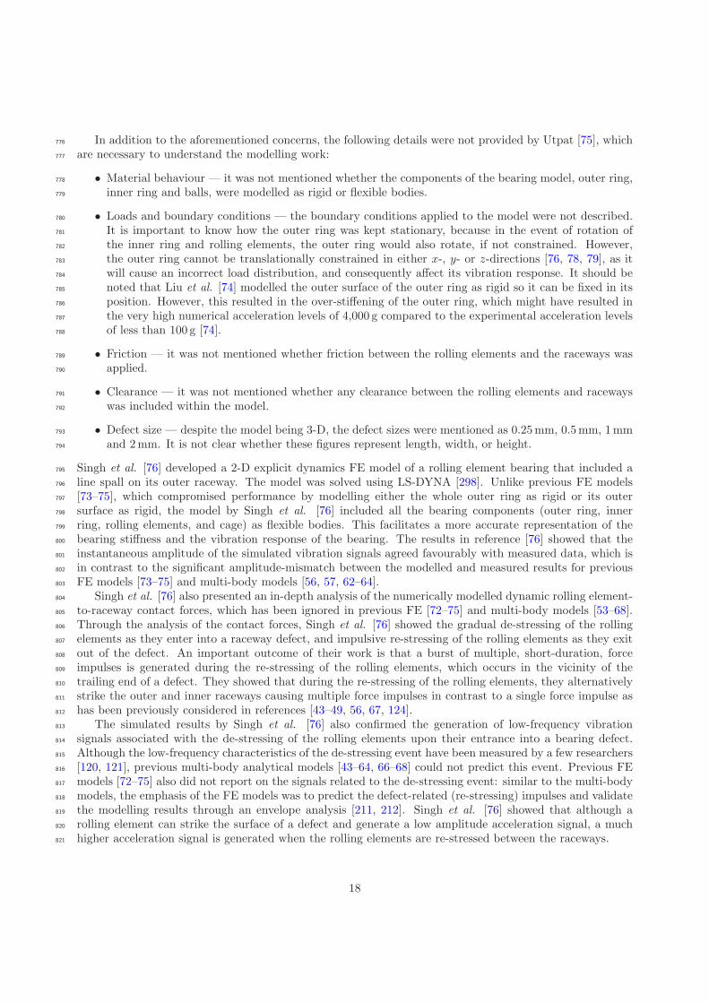
In addition to the aforementioned concerns, the following details were not provided by Utpat [75], which776
are necessary to understand the modelling work:777
• Material behaviour — it was not mentioned whether the components of the bearing model, outer ring,778
inner ring and balls, were modelled as rigid or flexible bodies.779
• Loads and boundary conditions — the boundary conditions applied to the model were not described.780
It is important to know how the outer ring was kept stationary, because in the event of rotation of781
the inner ring and rolling elements, the outer ring would also rotate, if not constrained. However,782
the outer ring cannot be translationally constrained in either x-, y- or z-directions [76, 78, 79], as it783
will cause an incorrect load distribution, and consequently affect its vibration response. It should be784
noted that Liu et al. [74] modelled the outer surface of the outer ring as rigid so it can be fixed in its785
position. However, this resulted in the over-stiffening of the outer ring, which might have resulted in786
the very high numerical acceleration levels of 4,000 g compared to the experimental acceleration levels787
of less than 100 g [74].788
• Friction — it was not mentioned whether friction between the rolling elements and the raceways was789
applied.790
• Clearance — it was not mentioned whether any clearance between the rolling elements and raceways791
was included within the model.792
• Defect size — despite the model being 3-D, the defect sizes were mentioned as 0.25mm, 0.5mm, 1mm793
and 2mm. It is not clear whether these figures represent length, width, or height.794
Singh et al. [76] developed a 2-D explicit dynamics FE model of a rolling element bearing that included a795
line spall on its outer raceway. The model was solved using LS-DYNA [298]. Unlike previous FE models796
[73–75], which compromised performance by modelling either the whole outer ring as rigid or its outer797
surface as rigid, the model by Singh et al. [76] included all the bearing components (outer ring, inner798
ring, rolling elements, and cage) as flexible bodies. This facilitates a more accurate representation of the799
bearing stiffness and the vibration response of the bearing. The results in reference [76] showed that the800
instantaneous amplitude of the simulated vibration signals agreed favourably with measured data, which is801
in contrast to the significant amplitude-mismatch between the modelled and measured results for previous802
FE models [73–75] and multi-body models [56, 57, 62–64].803
Singh et al. [76] also presented an in-depth analysis of the numerically modelled dynamic rolling element-804
to-raceway contact forces, which has been ignored in previous FE [72–75] and multi-body models [53–68].805
Through the analysis of the contact forces, Singh et al. [76] showed the gradual de-stressing of the rolling806
elements as they enter into a raceway defect, and impulsive re-stressing of the rolling elements as they exit807
out of the defect. An important outcome of their work is that a burst of multiple, short-duration, force808
impulses is generated during the re-stressing of the rolling elements, which occurs in the vicinity of the809
trailing end of a defect. They showed that during the re-stressing of the rolling elements, they alternatively810
strike the outer and inner raceways causing multiple force impulses in contrast to a single force impulse as811
has been previously considered in references [43–49, 56, 67, 124].812
The simulated results by Singh et al. [76] also confirmed the generation of low-frequency vibration813
signals associated with the de-stressing of the rolling elements upon their entrance into a bearing defect.814
Although the low-frequency characteristics of the de-stressing event have been measured by a few researchers815
[120, 121], previous multi-body analytical models [43–64, 66–68] could not predict this event. Previous FE816
models [72–75] also did not report on the signals related to the de-stressing event: similar to the multi-body817
models, the emphasis of the FE models was to predict the defect-related (re-stressing) impulses and validate818
the modelling results through an envelope analysis [211, 212]. Singh et al. [76] showed that although a819
rolling element can strike the surface of a defect and generate a low amplitude acceleration signal, a much820
higher acceleration signal is generated when the rolling elements are re-stressed between the raceways.821
18

3. Extended defects822
An extended defect can be characterised as a defect that is larger than a localised defect (for example,823
its size can be greater than the spacing between two rolling elements), but smaller than a distributed defect824
(for example, waviness is generally along full raceways). Once a localised defect (a spall) is created on either825
raceway of a bearing due to surface fatigue [3–5, 129–132], the continuous and repetitive passage of the826
rolling elements over the spall results in the generation of impulsive (contact) forces during the re-stressing827
of the rolling elements [76–79]. This cyclic operation wears the edges, especially the trailing edge, of the828
spall causing it to gradually grow or expand in size, and results in the generation of an extended defect829
[306].830
In contrast to localised [43–79] and distributed defects [81–119], extended defects have received much831
less attention. Only two publications [68, 80] could be found in the literature that discuss the vibration832
modelling of a rolling element bearing with an extended defect, and are discussed below.833
3.1. Nonlinear multi-body dynamic models834
Sawalhi et al. [80] extended their previous work [58] on the vibration modelling of a rolling element835
bearing with a localised defect (discussed in Section 2.3.3). They presented a combined nonlinear multi-836
body dynamic model for gears and bearings in which an extended defect on either of the two raceways can837
be studied in the presence of gear interaction. They characterised the extended defects as faults that extend838
beyond the spacing between two rolling elements, and have been smoothened by the successive passage839
of the rolling elements, so that no sharp impulses are generated, and no defect-related frequencies are840
detected in the envelope (demodulated) spectrum. They referred to the extended defects as rough surfaces.841
They modelled the inner and outer rings as rigid bodies, and the rolling element-to-raceway interfaces as842
nonlinear contact springs. The mass of the rolling elements, and their inertial and centrifugal effects were843
not considered due to the low run speeds used in the experiments. Slippage of the rolling elements [49]844
was included in their model to obtain a closer resemblance between the predicted and measured vibration845
spectra. Damping was included via a grounded damper attached to the inner raceway. An additional mass-846
spring-damper system, resonant-changer, representing a typical high-frequency bearing resonance (15 kHz)847
was attached to the outer raceway. The objective of the work presented by Sawalhi et al. [80] was the848
differential diagnosis of gear and bearing defects [49–51], which was achieved by utilising the difference in849
the cyclostationary properties of the gear and bearing signals [214, 215, 218]. The simulation results included850
acceleration signals for inner and outer raceway extended spalls, and their corresponding squared envelope851
[48] and cyclic spectral densities [17, 216, 217]. The results were compared with experimental data for a852
bearing where extended faults were etched on both of its raceways, and good similarity between the two853
results was achieved. Due to the rough surface characteristics of the extended defect, the use of the envelope854
spectrum did not identify the inner race defect frequency fbpi, whereas the spectral correlation function855
enabled detection of the defect frequencies.856
Petersen et al. [68] further modified the work of Sawalhi et al. [58, 80] to improve the prediction of the857
vibration modelling of defective bearings. Reference [68] included the modelling of the vibration response858
of a rolling element bearing with both localised and extended defects. A review of the model has already859
been provided in Section 2.3.3. Petersen et al. [68] showed that for an extended spall with large wavelength860
surface roughness (waviness) features, the stiffness of the bearing changes slowly than a localised narrow861
line spall that leads to the low-frequency parametric excitation of bearing structure. For the extended spall,862
the defect-related frequency components due to the excitation were clearly visible in the velocity spectra.863
4. Defect-related vibration characteristics864
The main objective of the models, impulse-train [43–52], multi-body [53–69], and FE models [70–75]865
(except [76]), reviewed so far was to predict the significant vibration frequency components; fundamental,866
harmonics, and associated sidebands, related to localised surface defects in rolling element bearings. The867
emphasis on investigating the change in the characteristics of bearing vibration signals at the edges of a868
19
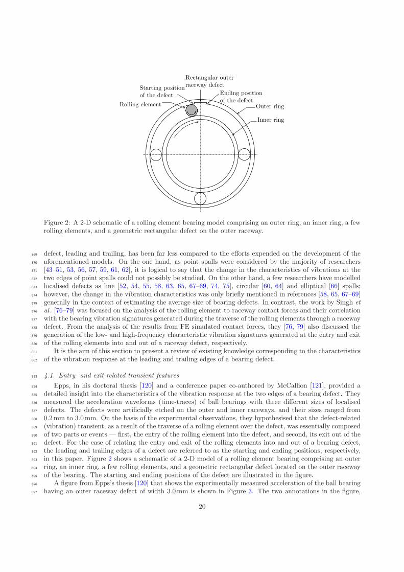
Figure 2: A 2-D schematic of a rolling element bearing model comprising an outer ring, an inner ring, a fewrolling elements, and a geometric rectangular defect on the outer raceway.
defect, leading and trailing, has been far less compared to the efforts expended on the development of the869
aforementioned models. On the one hand, as point spalls were considered by the majority of researchers870
[43–51, 53, 56, 57, 59, 61, 62], it is logical to say that the change in the characteristics of vibrations at the871
two edges of point spalls could not possibly be studied. On the other hand, a few researchers have modelled872
localised defects as line [52, 54, 55, 58, 63, 65, 67–69, 74, 75], circular [60, 64] and elliptical [66] spalls;873
however, the change in the vibration characteristics was only briefly mentioned in references [58, 65, 67–69]874
generally in the context of estimating the average size of bearing defects. In contrast, the work by Singh et875
al. [76–79] was focused on the analysis of the rolling element-to-raceway contact forces and their correlation876
with the bearing vibration signatures generated during the traverse of the rolling elements through a raceway877
defect. From the analysis of the results from FE simulated contact forces, they [76, 79] also discussed the878
generation of the low- and high-frequency characteristic vibration signatures generated at the entry and exit879
of the rolling elements into and out of a raceway defect, respectively.880
It is the aim of this section to present a review of existing knowledge corresponding to the characteristics881
of the vibration response at the leading and trailing edges of a bearing defect.882
4.1. Entry- and exit-related transient features883
Epps, in his doctoral thesis [120] and a conference paper co-authored by McCallion [121], provided a884
detailed insight into the characteristics of the vibration response at the two edges of a bearing defect. They885
measured the acceleration waveforms (time-traces) of ball bearings with three different sizes of localised886
defects. The defects were artificially etched on the outer and inner raceways, and their sizes ranged from887
0.2mm to 3.0mm. On the basis of the experimental observations, they hypothesised that the defect-related888
(vibration) transient, as a result of the traverse of a rolling element over the defect, was essentially composed889
of two parts or events — first, the entry of the rolling element into the defect, and second, its exit out of the890
defect. For the ease of relating the entry and exit of the rolling elements into and out of a bearing defect,891
the leading and trailing edges of a defect are referred to as the starting and ending positions, respectively,892
in this paper. Figure 2 shows a schematic of a 2-D model of a rolling element bearing comprising an outer893
ring, an inner ring, a few rolling elements, and a geometric rectangular defect located on the outer raceway894
of the bearing. The starting and ending positions of the defect are illustrated in the figure.895
A figure from Epps’s thesis [120] that shows the experimentally measured acceleration of the ball bearing896
having an outer raceway defect of width 3.0mm is shown in Figure 3. The two annotations in the figure,897
20
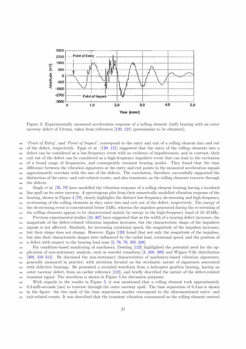
Figure 3: Experimentally measured acceleration response of a rolling element (ball) bearing with an outerraceway defect of 3.0mm, taken from references [120, 121] (permissions to be obtained).
‘Point of Entry ’, and ‘Point of Impact ’, correspond to the entry and exit of a rolling element into and out898
of the defect, respectively. Epps et al. [120, 121] suggested that the entry of the rolling elements into a899
defect can be considered as a low-frequency event with no evidence of impulsiveness, and in contrast, their900
exit out of the defect can be considered as a high-frequency impulsive event that can lead to the excitation901
of a broad range of frequencies, and consequently resonant bearing modes. They found that the time902
difference between the vibration signatures at the entry and exit points in the measured acceleration signals903
approximately correlate with the size of the defects. The correlation, therefore, successfully supported the904
distinction of the entry- and exit-related events, and also transients, as the rolling elements traverse through905
the defects.906
Singh et al. [76, 79] have modelled the vibration response of a rolling element bearing having a localised907
line spall on its outer raceway. A spectrogram plot from their numerically modelled vibration response of the908
bearing, shown in Figure 4 [79], clearly highlights the distinct low-frequency de-stressing and high-frequency909
re-stressing of the rolling elements as they enter into and exit out of the defect, respectively. The energy of910
the de-stressing event is concentrated below 3 kHz, whereas the impulses generated during the re-stressing of911
the rolling elements appear to be characterised mainly by energy in the high-frequency band of 10–25 kHz.912
Previous experimental studies [10, 307] have suggested that as the width of a bearing defect increases, the913
magnitude of the defect-related vibration impulses increases, but the characteristic shape of the impulsive914
signals is not affected. Similarly, for increasing rotational speed, the magnitude of the impulses increases,915
but their shape does not change. However, Epps [120] found that not only the magnitude of the impulses,916
but also their characteristic shapes were influenced by the radial load, rotational speed, and the position of917
a defect with respect to the bearing load zone [2, 76, 79, 205–208].918
For condition-based monitoring of machinery, Dowling [123] highlighted the potential need for the ap-919
plication of non-stationary analysis, such as wavelet transform [3, 308, 309] and Wigner-Ville distribution920
[308, 310–312]. He discussed the non-stationary characteristics of machinery-based vibration signatures,921
generally measured in practice, with attention focused on the stochastic nature of signatures associated922
with defective bearings. He presented a recorded waveform from a helicopter gearbox bearing, having an923
outer raceway defect, from an earlier reference [122], and briefly described the nature of the defect-related924
transient signal. The waveform is shown in Figure 5 for discussion purposes.925
With regards to the results in Figure 5, it was mentioned that a rolling element took approximately926
0.3milli-seconds (ms) to traverse through the outer raceway spall. The time separation of 0.3ms is shown927
in the figure: the two ends of the time separation marker correspond to the aforementioned entry- and928
exit-related events. It was described that the transient vibration commenced as the rolling element entered929
21
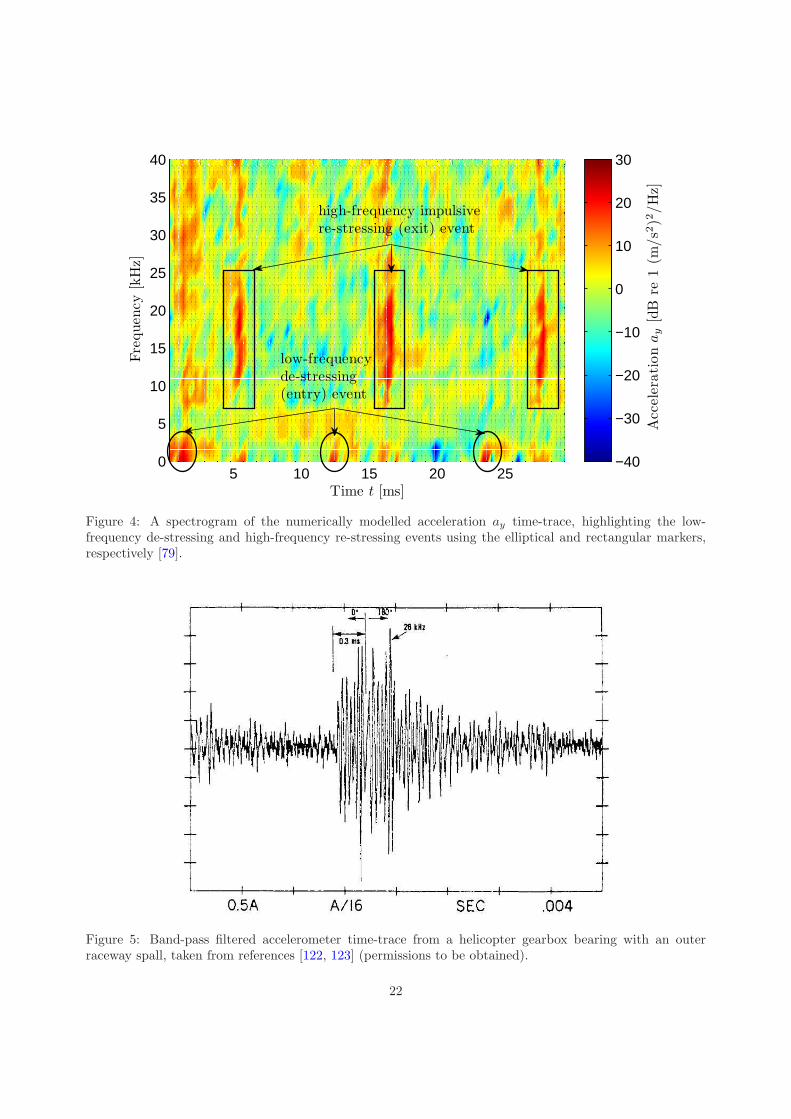
5 10 15 20 250
5
10
15
20
25
30
35
40
Time t [ms]
Fre
quen
cy[k
Hz]
Acc
eler
ati
on
ay
[dB
re1
(m/s2
)2/H
z]
−40
−30
−20
−10
0
10
20
30
high-frequency impulsivere-stressing (exit) event
low-frequencyde-stressing(entry) event
Figure 4: A spectrogram of the numerically modelled acceleration ay time-trace, highlighting the low-frequency de-stressing and high-frequency re-stressing events using the elliptical and rectangular markers,respectively [79].
Figure 5: Band-pass filtered accelerometer time-trace from a helicopter gearbox bearing with an outerraceway spall, taken from references [122, 123] (permissions to be obtained).
22
the defect, and upon its exit from the defect, an impact was generated that interfered with the transient930
that occurred at the beginning, resulting in a 180◦ phase shift. Thus, Dowling [123] related the change in931
the characteristics of the defect-related vibration signatures associated with the entry and exit of the rolling932
element into and out of the defect, respectively, by a 180◦ phase-reversal. However, no further discussion933
about to the charactersitics of the transient vibration response was provided.934
Although the results of Dowling [123] (Figure 5) are not as clear as those presented by Epps et al.935
[120, 121] (Figure 3), both represent similar findings — no evidence of impulsiveness at the entry of the936
rolling element into the defect, and impulse-like signatures at its exit out of the defect.937
A careful observation of Figure 5 shows an additional peak after the exit-related impulse; however, the938
occurrence of the multiple impulses was not discussed [123]. Sawalhi et al. [58] initially considered that the939
occurrence of the two impulses was associated with the entry and exit of the rolling elements into and out940
of a bearing defect, respectively; however, later on, they retracted their claim [124]. This double-impulse941
phenomenon is described in the next section.942
4.2. Double-impulse phenomenon943
Sawalhi et al. [58] observed double impulses in the results simulated using their proposed nonlinear multi-944
body dynamic model for predicting the vibration response of a rolling element bearing having a localised945
raceway defect. A review of their analytical model [58] has been provided in Section 2.3.3. Interestingly, they946
also found the presence of double impulses in the experimentally measured results. A figure that compares947
the measured and simulated results from their work [58], illustrating the presence of double impulses is948
shown in Figure 6. They mentioned that the time separation of 0.0013 seconds between the two impulses,949
highlighted in Figure 6, corresponds to the time that a rolling element takes to traverse the width of the950
outer raceway defect. The close match between the simulated and measured results not only helped Sawalhi951
et al. [58] validate their model, but also provided their results with a firm theoretical background, which952
appeared to be in agreement with the findings reported earlier by Epps et al. [120, 121] and Dowling [123].953
On the basis of the agreement, Sawalhi et al. [58] considered the two impulses to be associated with the954
entry and exit of the rolling elements into and out of the defect, respectively. They coined the phrase,955
‘double-impulse phenomenon’, to represent the occurrence of two defect-related vibration impulses.956
From the results presented in Figure 6 [58], it appears that the entry- and exit-related impulses have957
similar characteristics in terms of their frequency content. In other words, the results in Figure 6 imply that958
both entry- and exit-related events appear to be characterised by energies in high-frequency regions. This959
represents a stark contrast to previous results reported by Epps et al. [120, 121] and Dowling [123], who960
suggested that the entry of the rolling elements into a defect is a low-frequency event with no impulse-like961
characteristics. Although Sawalhi et al. [58] did not discuss the characteristics (frequency content) of the962
double impulses, the results presented in Figure 6 [58] imply that the entry of the rolling elements into a963
defect may not be a low-frequency event. As will be discussed in the next section, it is possible that there964
is an error associated with the results shown in Figure 6.965
4.2.1. Problems associated with the double-impulse phenomenon966
In 2011, Sawalhi et al. [124] reported results from a series of laboratory tests conducted on self-aligning967
double-row rolling element bearings with inner and outer raceway defects. Line spalls of width 0.6mm968
and 1.2mm were artificially manufactured on the raceways, and the tests were conducted at various shaft969
rotational speeds, ranging from 800 to 2400 revolutions per minute.970
In their earlier findings, as discussed in the preceding section (refer to Figure 6), Sawalhi et al. [58]971
mentioned that the time separation of 0.0013 seconds between the two impulses corresponds approximately972
to the time it takes for a rolling element to traverse the width of the manufactured outer raceway defect973
of 0.8mm. Later, they mentioned that the time separation actually corresponds to the time it takes for a974
rolling element to traverse the half the size of the defect. Furthermore, when they repeated the experiments975
at various shaft rotational speeds, they found that the time separation between the two impulses did not976
change [124]. Therefore, unlike their earlier findings [58] that implied that the entry of the rolling elements977
into a defect may not be a low-frequency event, the recent experimental findings by Sawalhi et al. [124]978
23

Figure 6: Band-pass filtered signals (one complete rotation of the shaft) with a spall in the outer race, takenfrom reference [58]: (a) measured, (b) simulated (permissions to be obtained).
correlate with those observed by Epps et al. [120, 121] and Dowling [123]; thereby, confirming the entry of979
the rolling elements into a defect as a low-frequency event.980
Invalidating the double-impulse phenomenon, Sawalhi et al. [124] suspected that the two impulses could981
be due to a beating effect related to a small difference in the resonance frequencies of a bearing possibly due982
to stiffness nonlinearity. From the survey of the literature conducted during the course of this paper, the983
reason for the occurrence of multiple impulses (as shown in Figure 6 as a result of a single rolling element984
traversing the defect in typically measured bearing vibration signals is not clearly known. Recently, Singh et985
al. [76] have provided an insightful explanation about the occurrence of the defect-related multiple impulses986
using the explicit dynamics FE modelling of a defective rolling element bearing as discussed in the next987
section.988
4.3. Physics behind the generation of defect-related impulses989
From the analysis of the FE simulated rolling element-to-raceway contact forces and their correlation990
with the bearing acceleration results, Singh et al. [76] showed that defect-related impulses, which are991
generally observed in measured bearing vibration signals, are generated during the re-stressing of the rolling992
elements. The re-stressing occurs in the vicinity of the end of a bearing defect as the rolling elements exit993
out of the defect. They [76] also explained that higher forces and stresses are generated during the exit994
of the rolling elements from the defect compared to when they strike the defect surface, and hence, could995
lead to the gradual expansion or lengthening of the defect. These findings show excellent agreement with996
24

the experimental study conducted by Hoeprich [306], who investigated the damage progression in rolling997
element bearings and found that the size of a spall progresses in the rolling direction.998
As opposed to the tentative explanation of beating about the occurrence of multiple impulses provided999
by Sawalhi et al. [124], Singh et al. [76] showed that a burst of multiple, short-duration, force impulses1000
are generated during the re-stressing of the rolling elements. These force impulses consequently cause1001
multiple vibration impulses that are caused as the rolling elements are compressed between the outer and1002
inner raceways. This is commonly observed in practice in measured bearing acceleration signals, which are1003
subsequently used for bearing diagnosis.1004
5. Defect size estimation1005
This section discusses existing knowledge on the estimation of the average size of a defect in rolling1006
element bearings. Similar to the literature on the vibration characteristics at the edges of a bearing defect,1007
the extent of knowledge for estimating the average size of a bearing defect is also limited.1008
It has previously been mentioned that a defect-related transient is composed of two parts [76, 79, 120, 121].1009
While the entry-related event is considered to be a low-frequency event, the exit of the rolling elements1010
from a defect is found to be a high-frequency impulsive event. From the results of the FE modelling of a1011
defective bearing and their subsequent comparison with measured data, Singh et al. [76, 79] highlighted the1012
distribution of the energies corresponding to the two events — < 3 kHz for the entry- and 10–25 kHz for1013
exit-related events.1014
Based on the distinct vibration signatures, Epps et al. [120, 121] suggested correlating the time difference1015
between the two events as a measure of an average defect size. Singh et al. [76, 79] also used the time1016
separation between the entry- and exit-related vibration signatures, and suggested a mathematical formula1017
to approximate the size of a defect.1018
5.1. Entry- and exit-related vibration models1019
On the basis of their experimental findings, Sawalhi et al. [124] suggested that the entry and exit of1020
the rolling elements into and out of a defect can be described as a step response and an impulse response,1021
respectively. They developed two analytical models in order to represent the two responses. While the1022
resonance frequency of 6500Hz used for the impulse response analytical model was selected on the basis of1023
the experimental results, no explanation was provided on the selection of the 1084Hz resonance frequency for1024
the step response analytical model, which was one-sixth of the resonance frequency of the impulse response.1025
In order to estimate the average size of a bearing defect, Sawalhi et al. [124] proposed two algorithms1026
to enhance the vibration signals related to the entry and exit of the rolling elements into and out of a1027
defect, respectively. The first algorithm comprised a joint treatment of the entry- and exit-related transient1028
signals. The signals were first pre-whitened using an autoregressive model [313, 314] in order to balance1029
the low- and high-frequency energies. The pre-whitened signals were then subjected to a complex octave1030
band wavelet analysis (using Morlet wavelets [315, 316]) to allow selection of the best band (or scale) to1031
balance the two events with similar frequency content. The squared envelope [48, 49] was generated next1032
using Hilbert transform methods [317, 318], and finally, a real cepstrum [319–321] was used to estimate the1033
average separation of the entry- and exit-related signatures. The second algorithm treated the entry- and1034
exit-related signatures separately; all the steps mentioned above were separately applied to the vibration1035
responses, so that they could be equally represented in the signal. A mathematical expression for estimating1036
half the actual width of a bearing defect was presented [124]. It was reported to be limited in its capacity1037
to estimate the smallest size of 0.6mm, but it was proposed that the results would perhaps be more reliable1038
for larger defects.1039
Zhao et al. [67] utilised the combination of empirical mode decomposition [314] and approximate entropy1040
method [322–325] to separate the entry- and exit-related transients. The vibration signals were decomposed1041
into finite components, called as intrinsic mode functions, using the empirical mode decomposition method.1042
The complexity in choosing the appropriate intrinsic mode functions that contain the defect-related entry-1043
and exit-related vibration signatures was demonstrated. Zhao et al. [67] compared their signal processing1044
25
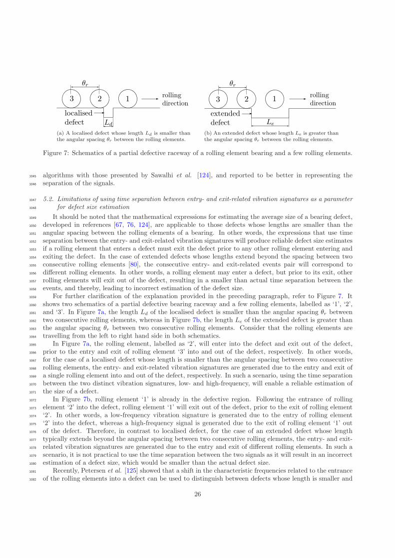
(a) A localised defect whose length Ld is smaller thanthe angular spacing θr between the rolling elements.
(b) An extended defect whose length Le is greater thanthe angular spacing θr between the rolling elements.
Figure 7: Schematics of a partial defective raceway of a rolling element bearing and a few rolling elements.
algorithms with those presented by Sawalhi et al. [124], and reported to be better in representing the1045
separation of the signals.1046
5.2. Limitations of using time separation between entry- and exit-related vibration signatures as a parameter1047
for defect size estimation1048
It should be noted that the mathematical expressions for estimating the average size of a bearing defect,1049
developed in references [67, 76, 124], are applicable to those defects whose lengths are smaller than the1050
angular spacing between the rolling elements of a bearing. In other words, the expressions that use time1051
separation between the entry- and exit-related vibration signatures will produce reliable defect size estimates1052
if a rolling element that enters a defect must exit the defect prior to any other rolling element entering and1053
exiting the defect. In the case of extended defects whose lengths extend beyond the spacing between two1054
consecutive rolling elements [80], the consecutive entry- and exit-related events pair will correspond to1055
different rolling elements. In other words, a rolling element may enter a defect, but prior to its exit, other1056
rolling elements will exit out of the defect, resulting in a smaller than actual time separation between the1057
events, and thereby, leading to incorrect estimation of the defect size.1058
For further clarification of the explanation provided in the preceding paragraph, refer to Figure 7. It1059
shows two schematics of a partial defective bearing raceway and a few rolling elements, labelled as ‘1’, ‘2’,1060
and ‘3’. In Figure 7a, the length Ld of the localised defect is smaller than the angular spacing θr between1061
two consecutive rolling elements, whereas in Figure 7b, the length Le of the extended defect is greater than1062
the angular spacing θr between two consecutive rolling elements. Consider that the rolling elements are1063
travelling from the left to right hand side in both schematics.1064
In Figure 7a, the rolling element, labelled as ‘2’, will enter into the defect and exit out of the defect,1065
prior to the entry and exit of rolling element ‘3’ into and out of the defect, respectively. In other words,1066
for the case of a localised defect whose length is smaller than the angular spacing between two consecutive1067
rolling elements, the entry- and exit-related vibration signatures are generated due to the entry and exit of1068
a single rolling element into and out of the defect, respectively. In such a scenario, using the time separation1069
between the two distinct vibration signatures, low- and high-frequency, will enable a reliable estimation of1070
the size of a defect.1071
In Figure 7b, rolling element ‘1’ is already in the defective region. Following the entrance of rolling1072
element ‘2’ into the defect, rolling element ‘1’ will exit out of the defect, prior to the exit of rolling element1073
‘2’. In other words, a low-frequency vibration signature is generated due to the entry of rolling element1074
‘2’ into the defect, whereas a high-frequency signal is generated due to the exit of rolling element ‘1’ out1075
of the defect. Therefore, in contrast to localised defect, for the case of an extended defect whose length1076
typically extends beyond the angular spacing between two consecutive rolling elements, the entry- and exit-1077
related vibration signatures are generated due to the entry and exit of different rolling elements. In such a1078
scenario, it is not practical to use the time separation between the two signals as it will result in an incorrect1079
estimation of a defect size, which would be smaller than the actual defect size.1080
Recently, Petersen et al. [125] showed that a shift in the characteristic frequencies related to the entrance1081
of the rolling elements into a defect can be used to distinguish between defects whose length is smaller and1082
26

greater than the angular spacing of the rolling elements. They showed that as the size of a defect varies, the1083
stiffness and the natural frequencies of the rigid body modes of a ball bearing assembly vary. Compared to a1084
non-defective bearing, the change occurs more rapidly as the rolling elements enter into and exit out of the1085
defects. The variation in the stiffness subsequently leads to the parametric excitation of the bearing at the1086
defect frequency resulting in the generation of low-frequency events with different characteristic frequencies.1087
The difference can be used to distinguish between the two defects provided the static load on a bearing1088
remains constant. However, the simulation results in reference [125] need experimental validation.1089
6. Summary of literature1090
The existing models for predicting the vibration response of rolling element bearings with localised defects1091
have provided an excellent understanding of the defect-related vibration frequency components. Several1092
authors have used analytical, numerical, FE, and a combination of analytical/numerical and FE methods1093
to predict the vibration response of bearings and associated rotor–bearing systems. The characteristics of1094
vibrations at the starting and ending positions of a defect have also been well-established. This section aims1095
to summarise the review of the literature presented in this paper followed by some future research directions1096
in the concluding section.1097
Impulse-train models. Periodic impulse-train models [43–46] to simulate point defects on the rolling surfaces1098
of a bearing, outer and inner raceways, and a rolling element, provided useful insights into understanding the1099
presence of various discrete frequency components in typically measured bearing acceleration signals. The1100
defect-induced force impulses were generated using the Dirac delta function and a 1-DOF system response.1101
Three typical pulse shapes, rectangular, triangular and half-sine, of finite widths were considered, and their1102
effects on the vibration (line) spectra, including frequencies and amplitudes, were investigated under radial1103
and axial loads [46]. The equi-spaced force impulses of equal amplitude were modelled for the case of a1104
stationary outer raceway bearing defect [45, 46], whereas for rotating inner raceway [43–46] and rolling1105
element defects [45, 46], the amplitude of the impulses was modulated as per the static load distribution1106
[2, 205–208] within a bearing. The periodic impulse-train models were extended [47–51] with the inclusion of1107
the slippage of the rolling elements [48, 49], so as to gain close agreement with typical vibration measurements1108
obtained in practice.1109
The impulse-train models successfully predict the significant defect-related frequencies (fundamental,1110
sidebands, and harmonics); however, they could not provide a reasonable prediction of their amplitudes.1111
The problem was specifically highlighted by Tandon et al. [46] who showed the comparison of the pre-1112
dicted vibration (line) spectra with experimentally measured results; other authors only provided defect1113
periodicities [43, 45]. The problem of amplitude mismatch is largely due to the following factors:1114
• the mismatch between the mathematically modelled defect-related impulses (rectangular, triangular,1115
and half-sine) and unknown characteristics of actual defect-induced impulses,1116
• the exclusion of basic bearing components, such as the outer ring, inner ring and rolling elements,1117
and structure from the analytical models compared to measuring the vibration response of a bearing,1118
which is generally installed in some kind of housing, such as a pedestal, and1119
• the consideration of several assumptions and simplifications during the development of the models.1120
The amplitudes of the frequency components were also normalised or corrected; however, neither the nor-1121
malisation factor was provided nor the mathematics behind the normalisation factor were discussed [46].1122
Nonlinear multi-body dynamic models. Unlike the impulse-train models, the nonlinear multi-body dynamic1123
models [53–69, 80] include various components of a rolling element bearing, and predict the vibration1124
response of bearings, bearing–pedestal and rotor–bearing systems, due to the presence of localised and1125
extended bearing defects. The localised defects not only include point spalls [53, 56, 57, 59, 61, 62] (as1126
was inadvertently the case for the impulse-train models [43–46]), but also circular spalls [60, 64], elliptical1127
27
spalls (ellipsoids) [66] (as a function of Hertzian contact deformation), and line (rectangular) spalls [54,1128
55, 58, 63, 65, 67–69] (as a function of width and depth). The multi-body models simplify the bearing1129
systems as lumped mass-spring-damper systems. They neglect the bending deformation of the outer and1130
inner rings [53–65, 68, 69], except in references [66, 67], and model the rolling element-to-raceway contacts1131
as nonlinear springs. The majority of the models that consider displacements in the radial plane were 2-D1132
[53–58, 60, 62–64, 66–69]; however, some also consider displacements in the axial plane [59, 61, 65]. While1133
the rolling elements were excluded in many models [53–56, 58–60, 62–64, 67], they were included in a few1134
models [57, 61, 65, 66] as point masses; however, their inertial and centrifugal effects were mostly ignored1135
[57, 61]. The slippage of the rolling elements was only considered by a few authors [58, 65, 66, 68, 69]1136
in order to gain close resemblance with a typical vibration response measured in practice, and ignored by1137
the rest. While localised damping at the contact interfaces between the rolling elements and raceways was1138
included in a few models [56, 57, 59, 68, 69], global (structural) damping [53–55, 58, 61–67] was included1139
in majority of the models by grounding a linear viscous damper to either the inner raceway (shaft) [61–64]1140
or outer raceway (pedestal) [53–55, 58, 63]. All the models predicted the time domain vibration response1141
of the outer ring/housing and inner ring [53–60, 62–69]; however, one model predicted the time domain1142
displacement of the rolling elements [61].1143
The main emphasis of the multi-body models was to demonstrate the generation of vibration time-1144
traces, and subsequently perform an envelope analysis [211, 212] on the simulated signals to primarily1145
predict the defect-related frequency components and corresponding sidebands for model validation purposes.1146
The problem of amplitude-mismatch between modelled and measured vibration frequencies observed in the1147
impulse-train models [44, 46] was also reported by the authors of the multi-body models [56, 57, 62–64].1148
While in some cases, the predicted amplitudes have simply been corrected based on experimental results1149
without providing an explanation [56, 57], some did not compare the modelling results with experimental1150
measurements [53–55, 59–61, 66]; they instead compared the results with previous studies in the literature.1151
Explicit dynamic FE models. Explicit dynamic FE modelling of rolling element bearings, using a commercial1152
FE software package, LS-DYNA [298], has been presented by five authors [72–76]. One of the advantages1153
of using such a code is that one can minimise the number of assumptions that are generally considered1154
in analytical methods. For example, the outer and inner rings, and rolling elements can be modelled as1155
flexible bodies, the inertial and centrifugal effects of the rolling elements can be modelled, the dynamic1156
contact interaction between the rolling elements and raceways can be studied, and above all, the interaction1157
of defective and non-defective bearing components can be investigated. However, the majority of the FE1158
models [72–75], except the model presented in reference [76], did not fully exploit the benefits of the explicit1159
FE methods. The performance of the models [72–75] was compromised because either the whole outer ring1160
of the bearing [73] or its outer surface [74] was modelled as rigid. The material behaviour, rigid or flexible,1161
of the bearing components was not mentioned in references [72, 75]. In contrast, all the components of a1162
bearing, such as outer and inner rings, rolling elements and cage, were modelled as flexible bodies in reference1163
[76]; thereby, representing more accurate bearing stiffness and consequently the vibration response.1164
Unrealistically high instantaneous acceleration levels of magnitudes 107 g, 4,000 g, and 15,000 g were1165
reported in references [73], [74], and [75], respectively, whereas realistic levels of 180 g were shown in reference1166
[76]. While no experimental results were shown in references [72, 73], the measured acceleration levels were1167
shown as 100 g and 10 g in references [74] and [75] compared to the simulated levels of 4,000 g and 15,000 g,1168
respectively. A favourable comparison between the modelled and measured vibration response of a rolling1169
element bearing was reported in reference [76]. Furthermore, the numerically modelled results were low-pass1170
filtered with a cut-off frequency of either 500Hz or 800Hz resulting in the elimination of all high-frequency1171
characteristics of the defect-related impulses [74]. As the FE modelling results were not validated against1172
the experimental results due to the significant mismatch between their acceleration levels [74, 75], they were1173
validated on the basis of the comparison of their predicted frequency components with those of the basic1174
bearing kinematic frequencies. The work presented in reference [76] not only provided an experimental1175
verification of the FE simulated vibration response, but also reported on the favourable agreement of the1176
FE simulated and analytically estimated rolling element-to-raceway contact forces [79].1177
Dynamic interaction of the rolling elements with raceways (rolling element-to-raceway contact forces)1178
28
was only presented in reference [76] and ignored by the rest who presented explicit FE [72–75] and multi-1179
body models [53–67]. An in-depth analysis of the contact forces and their correlation with the bearing1180
vibration signals led to an explanation of the physical mechanism by which defect-related impulsive forces,1181
and consequently vibrations, are generated in defective rolling element bearings [76]. It has also been1182
highlighted that a much higher acceleration signal is generated when a rolling element re-stresses between1183
the raceways compared to when it strikes a defective raceway surface within a bearing [76].1184
Defect-related vibration characteristics. It was found that a defect-related transient vibration signal is com-1185
posed of two parts/events [76, 79, 120, 121, 124]; 1) the entry of rolling elements into a defect, and 2) the exit1186
of the rolling elements out of the defect. While the entry-related event was considered to be a low-frequency1187
event with no indication of impulse-like characteristics [76, 79, 120, 121, 124], the exit-related event was1188
considered to be a high-frequency event that is responsible for generating a burst of multiple, short-duration,1189
impulses [76–79]. These impulses, which are generally observed in practice in measured bearing acceleration1190
signals, excite a broad range of frequencies that can cause the ringing of bearing resonant modes. The1191
energy distribution of the modelled vibration signatures associated with the entry- and exit-related events1192
was highlighted on a spectrogram plot (time–frequency diagram) [79]. With the aim of estimating the aver-1193
age size of a defect, a few authors have proposed algorithms (signal processing techniques) to enhance the1194
separation of the entry- and exit-related vibration signatures [67, 124], whereas some [76, 79, 120, 121] used1195
the time-separation between the distinct signatures.1196
7. Future research directions1197
A number of authors have contributed significantly to a variety of aspects related to rolling element1198
bearings since the late 1800s [153]. These aspects broadly range from understanding the onset of subsurface1199
fatigue cracks and their subsequent growth to surface spalls [4, 5, 129–132], to the development of bearing life1200
prediction models [154–191], to understanding the science of bearing materials for enhancing the material1201
quality [139–149] in order to increase bearing life. The kinematics and dynamics [133, 326–341] of rolling1202
element bearings have been understood, and several commercial codes and software packages are available to1203
solve the dynamics of rolling element bearings — ADORE (Advanced Dynamics of Rolling Elements) [342],1204
COBRA (Computer Optimized Ball and Roller Bearing Analysis) [343], BEAST (Bearing Simulation Tool)1205
[344], and IBDAS (Integrated Bearing Dynamic Analysis System) [345]. The vibration response for non-1206
defective [19–42] and defective rolling element bearings [43–119] along with the diagnosis of rolling element1207
bearing faults [3, 6–18] have also been well documented in the literature. Despite a wealth of literature, a1208
few research directions are discussed in the concluding paragraphs to be followed.1209
To investigate the effects on the vibration characteristics of defective rolling element bearings, a full1210
parametric study could be conducted that could include a matrix of parameters, which can be varied. These1211
parameters may include load (both radial and axial) on a bearing, rotational speed, clearance within a1212
bearing, and various defect types. The types of bearing defects may range from line, to area, to extended1213
area spalls having different profiles of surface roughness, which can be made similar to operational defects1214
observed in real-world applications. The location of raceway spalls could also be varied in and out of the1215
bearing load zone so that differences between the vibration responses could be studied.1216
In addition to investigating the vibration response of defective bearings, acoustic radiation from the1217
bearings should also be studied. An interesting area where noise from rolling element bearings is primarily1218
used for their diagnosis is the railway industry [79]. Bearing acoustic monitors [346], initially tested in the1219
1980s [347–350], are commonly used these days in the industry to detect defective bearings of a travelling1220
train using the acquired noise signals [351–354].1221
Understanding the vibro-acoustic characteristics of various defect types would not only improve the1222
diagnosis of defective bearings but also result in a reliable prognosis of the defects. This would result in1223
estimating the remaining useful life of a bearing, eventually saving significant operational and maintenance1224
costs.1225
29

Acknowledgments1226
This work was conducted as a part of ARC Linkage funded project LP110100529.1227
Appendix A. Bearing Defect Frequencies1228
For the case of a stationary outer ring and rotating inner ring, following are the characteristic defect1229
frequencies of a rolling element bearing rotating at a frequency fs [2, page 994]:1230
fc =fs2
(
1−Dr
Dp
cosα
)
(A.1)
fbpo =fs ×Nr
2
(
1−Dr
Dp
cosα
)
(A.2)
fbpi =fs ×Nr
2
(
1 +Dr
Dp
cosα
)
(A.3)
fbs =fs ×Dp
2×Dr
[
1−
(
Dr
Dp
cosα
)2]
(A.4)
fc cage frequency, commonly referred to as fundamental train frequency — it is the rotational speed of the1231
cage in a rolling element bearing,1232
fbpo ball pass frequency outer raceway (BPFO), commonly referred to as outer raceway defect frequency —1233
it is the rate at which the rolling elements pass a point on the outer raceway within a rolling element1234
bearing,1235
fbpi ball pass frequency inner raceway (BPFI), commonly referred to as inner raceway defect frequency —1236
it is the rate at which the rolling elements pass a point on the inner raceway within a rolling element1237
bearing,1238
fbs ball spin frequency (BSF), commonly referred to as ball or roller defect frequency — it is the rate of1239
rotation of a rolling element about its own axis,1240
Dp bearing pitch diameter,1241
Dr rolling element diameter,1242
Nr number of rolling elements, and1243
α contact angle.1244
These frequencies are kinematic frequencies that are based on the geometry of a rolling element bearing.1245
These frequencies do no take into account the slippage of the rotating components. As a result, actual1246
characteristic defect frequencies slightly differ from those predicted using the aforementioned equations.1247
[1] H. T. Morton, Anti-Friction Bearings, Second Edition, Ann Arbor, MI, 1965.[2] T. A. Harris, Rolling Bearing Analysis, Fourth Edition, John Wiley & Sons, 2001.[3] I. Howard, A review of rolling element bearing vibration: “detection, diagnosis and prognosis”, Tech. Rep. DSTO-RR-
0013, Defence Science and Technology Organisation, Australia (October 1994).[4] W. E. Littmann, The mechanism of contact fatigue, in: P. M. Ku (Ed.), Interdisciplinary approach to the lubrication of
concentrated contacts, no. NASA SP-237, National Aeronautics and Space Administration, Washington, DC, 1970, pp.309–378.
[5] W. E. Littmann, R. L. Widner, Propagation of contact fatigue from surface and subsurface origins, Journal of BasicEngineering 88 (3) (1966) 624–636. doi:10.1115/1.3645922.
[6] N. Tandon, A. Choudhury, A review of vibration and acoustic measurement methods for the detection of defects in rollingelement bearings, Tribology International 32 (8) (1999) 469–480. doi:10.1016/S0301-679X(99)00077-8.
30

[7] D. R. Houser, M. J. Drosjack, Vibration signal analysis techniques, Tech. rep., U.S. Army Air Mobility Research andDevelopment Laboratory (1973).
[8] R. A. Collacott, Vibration monitoring and diagnosis, Techniques for Cost-effective Plant Maintenance, Halsted Press,John Wiley & Sons, Inc., New York, 1979.
[9] L. M. Roger, The application of vibration analysis and acoustic emission source location to on-line condition monitoringof anti-friction bearings, Tribology International 12 (2) (1979) 51–58. doi:10.1016/0301-679X(79)90001-X.
[10] N. S. Swansson, S. C. Favaloro, Applications of vibration analysis to the condition monitoring of rolling element bearings,Tech. Rep. ARL-AERO-PROP-R-163, Defence Science and Technology Organisation, Australia (January 1984).
[11] A. Choudhury, N. Tandon, Application of acoustic emission technique for the detection of defects in rolling elementbearings, Tribology International 33 (1) (2000) 39–45. doi:10.1016/S0301-679X(00)00012-8.
[12] J. Antoni, The spectral kurtosis: A useful tool for characterising non-stationary signals, Mechanical Systems and SignalProcessing 20 (2) (2006) 282–307. doi:10.1016/j.ymssp.2004.09.001.
[13] J. Antoni, R. B. Randall, The spectral kurtosis: Application to the vibratory surveillance and diagnostics of rotatingmachines, Mechanical Systems and Signal Processing 20 (2) (2006) 308–331. doi:10.1016/j.ymssp.2004.09.002.
[14] J. Antoni, Fast detection of the kurtogram for the detection of transient faults, Mechanical Systems and Signal Processing21 (1) (2007) 108–124. doi:10.1016/j.ymssp.2005.12.002.
[15] D. Mba, B. K. N. Rao, Development of acoustic emission technology for condition monitoring and diagnosis of rotatingmachines; bearings, pumps, gearboxes, engines and rotating structures, The Shock and Vibration Digest 38 (1) (2006)3–16. doi:10.1177/0583102405059054.
[16] A. K. S. Jardine, D. Lin, D. Banjevic, A review on machinery diagnostics and prognostics implementing condition-basedmaintenance, Mechanical Systems and Signal Processing 20 (7) (2006) 1483–1510. doi:10.1016/j.ymssp.2005.09.012.
[17] R. B. Randall, J. Antoni, Rolling element bearing diagnostics — A tutorial, Mechanical Systems and Signal Processing25 (2) (2011) 485–520. doi:10.1016/j.ymssp.2010.07.017.
[18] R. B. Randall, Vibration-based condition monitoring, First Edition, Industrial, aerospace, and automotive applications,John Wiley & Sons, Ltd, 2011.
[19] H. Perret, Elastische Spielschwingungen konstant belasteter Walzlager, Werkstatt und Betrieb 83 (8) (1950) 354–358.[20] H. Perret, Die Lagerluft als Bestimmungsgrosse fur die Beanspruchungeines Walzlagers, Werkstatt und Betrieb 83 (4)
(1950) 131–134.[21] H. Perret, Schwingungen in Walzlagern bei statisch bestimmter Abstutzung, VDI-Forschungs (434) (1952) 17–28.[22] H. Perret, Walzlager als Schwingungserreger, Werkstattstechnik und Maschinenbau 40 (1) (1950) 5–9.[23] E. Meldau, Die Bewegung der Achse von Walzlagern bei geringen Drehzahlen, Werkstatt und Betrieb 84 (7) (1951)
308–313.[24] E. Meldau, Werkstatt und Betrieb 84 (4) (1951) 143.[25] E. Meldau, Werkstatt und Betrieb 85 (2) (1952) 56.[26] E. Meldau, Konstruktion 4 (3) (1952) 79.[27] T. E. Tallian, O. G. Gustafsson, The mechanics of rolling-element bearing vibrations, Transactions of the American
Society of Mechanical Engineers Paper No. 58-A-292.[28] A. Tamura, O. Taniguchi, Ball bearing vibrations: 1st Report, On the radial vibration caused by passing balls, Transac-
tions of The Japan Society of Mechanical Engineers 26 (161) (1960) 19–25. doi:10.1299/kikai1938.26.19.[29] A. Tamura, O. Taniguchi, Ball bearing vibrations: 2nd Report, On the subharmonic vibration of order 1/2
caused by passing balls, Transactions of The Japan Society of Mechanical Engineers 26 (167) (1960) 877–883.doi:10.1299/kikai1938.26.877.
[30] A. Tamura, O. Taniguchi, Ball bearing vibrations: 3rd Report, On the axial vibration caused by passing balls, Transac-tions of The Japan Society of Mechanical Engineers 26 (170) (1960) 1428–1434. doi:10.1299/kikai1938.26.1428.
[31] A. Tamura, O. Taniguchi, Ball bearing vibrations: 4th Report, On the nonlinear vibrations in axial direction, Transactionsof The Japan Society of Mechanical Engineers 27 (179) (1961) 1146–1153. doi:10.1299/kikai1938.27.1146.
[32] A. Tamura, O. Taniguchi, Ball bearing vibrations: 5th Report, On the device to reduce the vibration causedby a ball bearing, Transactions of The Japan Society of Mechanical Engineers 27 (182) (1962) 1505–1509.doi:10.1299/kikai1938.27.1509.
[33] A. Tamura, O. Taniguchi, Ball bearing vibrations: 6th Report, On the vibration of a ball bearing under light load,Transactions of The Japan Society of Mechanical Engineers 28 (188) (1962) 492–499. doi:10.1299/kikai1938.28.492.
[34] H. Tamura, Y. Tsuda, On the spring characteristics of a ball bearing: extreme characteristics with many balls, Bulletinof The Japan Society of Mechanical Engineers 23 (180) (1980) 961–969. doi:10.1299/jsme1958.23.961.
[35] H. Tamura, Y. Tsuda, On the spring characteristics of a ball bearing: fluctuation due to ball revolution, Bulletin of TheJapan Society of Mechanical Engineers 23 (185) (1980) 1905–1912. doi:10.1299/jsme1958.23.1905.
[36] H. Tamura, E. H. Gad, T. Kondou, Y. Tsuda, A. Sueoka, The static running accuracy of ball bearings, Memoirs of theFaculty of Engineering 43 (4) (1983) 285–316.
[37] E. H. Gad, T. Kondou, H. Tamura, Spring property of ball bearing, Memoirs of the Faculty of Engineering 43 (3) (1983)243–264.
[38] E. H. Gad, S. Fukata, H. Tamura, Computer simulation of rotor radial vibrations due to ball bearings, Memoirs of theFaculty of Engineering 44 (1) (1984) 83–111.
[39] E. H. Gad, S. Fukata, H. Tamura, Computer simulation of rotor axial and radial vibrations based on ball bearings,Memoirs of the Faculty of Engineering 44 (2) (1984) 169–183.
[40] S. Fukata, E. H. Gad, T. Kondou, T. Ayabe, H. Tamura, On the radial vibration of ball bearings: computer simulation,Bulletin of The Japan Society of Mechanical Engineers 28 (239) (1985) 899–904. doi:10.1299/jsme1958.28.899.
31

[41] H. Tamura, E. H. Gad, T. Kondou, T. Ayabe, A. Sueoka, On the static running accuracy of ball bearings, Bulletin ofThe Japan Society of Mechanical Engineers 28 (240) (1985) 1240–1246. doi:10.1299/jsme1958.28.1240.
[42] S. H. Ghafari, E. M. Rahman, F. Golnaraghi, F. Ismail, Vibrations of balanced fault-free ball bearings, Journal of Soundand Vibration 329 (9) (2010) 1332–1347. doi:10.1016/j.jsv.2009.11.003.
[43] P. D. McFadden, J. D. Smith, Model for the vibration produced by a single point defect in a rolling element bearing,Journal of Sound and Vibration 96 (1) (1984) 69–82. doi:10.1016/0022-460X(84)90595-9.
[44] P. D. McFadden, J. D. Smith, The vibration produced by multiple point defects in a rolling element bearing, Journal ofSound and Vibration 98 (2) (1985) 263–273. doi:10.1016/0022-460X(85)90390-6.
[45] Y. T. Su, S. J. Lin, On initial fault detection of a tapered roller bearing: Frequency domain analysis, Journal of Soundand Vibration 155 (1) (1992) 75–84. doi:10.1016/0022-460X(92)90646-F.
[46] N. Tandon, A. Choudhury, An analytical model for the prediction of the vibration response of rolling element bearingsdue to a localized defect, Journal of Sound and Vibration 205 (3) (1997) 275–292. doi:10.1006/jsvi.1997.1031.
[47] D. Brie, Modelling of the spalled rolling element bearing vibration signal: An overview and some new results, MechanicalSystems and Signal Processing 14 (3) (2000) 353–369. doi:10.1006/mssp.1999.1237.
[48] D. Ho, R. B. Randall, Optimisation of bearing diagnostics techniques using simulated and actual bearing fault signals,Mechanical Systems and Signal Processing 14 (5) (2000) 763–788. doi:10.1006/mssp.2000.1304.
[49] R. B. Randall, J. Antoni, S. Chobsaard, The relationship between spectral correlation and envelope analysis in thediagnostics of bearing faults and other cyclostationary machine signals, Mechanical Systems and Signal Processing 15 (5)(2001) 945–962. doi:10.1006/mssp.2001.1415.
[50] J. Antoni, R. B. Randall, Differential diagnosis of gear and bearing faults, Journal of Vibration and Acoustics 124 (2)(2002) 165–171. doi:10.1115/1.1456906.
[51] J. Antoni, R. B. Randall, A stochastic model for simulation and diagnostics of rolling element bearings with localizedfaults, Journal of Vibration and Acoustics 125 (3) (2003) 282–289. doi:10.1115/1.1569940.
[52] M. Behzad, A. R. Bastami, D. Mba, A new model for estimating vibrations generated in the defective rolling elementbearings, Journal of Vibration and Acoustics 133 (4) (2011) 041011 (8 pages). doi:10.1115/1.4003595.
[53] N. S. Feng, E. J. Hahn, R. B. Randall, Using transient analysis software to simulate vibration signals due to rollingelement bearing defects, in: Proceedings of the Third Australian Congress on Applied Mechanics, Sydney, 2002, pp.689–694.
[54] J. Sopanen, A. Mikkola, Dynamic model of a deep-groove ball bearing including localized and distributed defects. Part 1:Theory, Proceedings of the Institution of Mechanical Engineers, Part K: Journal of Multi-body Dynamics 217 (3) (2003)201–211. doi:10.1243/14644190360713551.
[55] J. Sopanen, A. Mikkola, Dynamic model of a deep-groove ball bearing including localized and distributed defects. Part2: Implementation and results, Proceedings of the Institution of Mechanical Engineers, Part K: Journal of Multi-bodyDynamics 217 (3) (2003) 213–233. doi:10.1243/14644190360713560.
[56] A. Choudhury, N. Tandon, Vibration response of rolling element bearings in a rotor bearing system to a local defectunder radial load, Journal of Tribology 128 (2) (2006) 252–261. doi:10.1115/1.2164467.
[57] S. Sassi, B. Badri, M. Thomas, A numerical model to predict damaged bearing vibrations, Journal of Vibration andControl 13 (11) (2007) 1603–1628. doi:10.1177/1077546307080040.
[58] N. Sawalhi, R. B. Randall, Simulating gear and bearing interactions in the presence of faults. Part I: The combined gearbearing dynamic model and the simulation of localised bearing faults, Mechanical Systems and Signal Processing 22 (8)(2008) 1924–1951. doi:10.1016/j.ymssp.2007.12.001.
[59] M. Cao, J. Xiao, A comprehensive dynamic model of double-row spherical roller bearing — Model development andcase studies on surface defects, preloads, and radial clearance, Mechanical Systems and Signal Processing 22 (2) (2008)467–489. doi:10.1016/j.ymssp.2007.07.007.
[60] A. Ashtekar, F. Sadeghi, L.-E. Stacke, A new approach to modeling surface defects in bearing dynamics simulations,Journal of Tribology 130 (4) (2008) 041103 (8 pages). doi:10.1115/1.2959106.
[61] H. Arslan, N. Akturk, An investigation of rolling element vibrations caused by local defects, Journal of Tribology 130 (4)(2008) 041101 (12 pages). doi:10.1115/1.2958070.
[62] A. Rafsanjani, S. Abbasion, A. Farshidianfar, H. Moeenfard, Nonlinear dynamic modeling of surface defects in rollingelement bearing systems, Journal of Sound and Vibration 319 (3–5a) (2009) 1150–1174. doi:10.1016/j.jsv.2008.06.043.
[63] V. N. Patel, N. Tandon, R. K. Pandey, A dynamic model for vibration studies of deep groove ball bearings consideringsingle and multiple defects in races, Journal of Tribology 132 (4) (2010) 041101 (10 pages). doi:10.1115/1.4002333.
[64] M. S. Patil, J. Mathew, P. K. Rajendrakumar, S. Desai, A theoretical model to predict the effect of localized de-fect on vibrations associated with ball bearing, International Journal of Mechanical Sciences 52 (9) (2010) 1193–1201.doi:10.1016/j.ijmecsci.2010.05.005.
[65] M. Nakhaeinejad, M. D. Bryant, Dynamic modeling of rolling element bearings with surface contact defects using bondgraphs, Journal of Tribology 133 (1) (2011) 011102 (12 pages). doi:10.1115/1.4003088.
[66] M. Tadina, M. Boltezar, Improved model of a ball bearing for the simulation of vibration signals due to faults duringrun-up, Journal of Sound and Vibration 330 (17) (2011) 4287–4301. doi:10.1016/j.jsv.2011.03.031.
[67] S. Zhao, L. Liang, G. Xu, J. Wang, W. Zhang, Quantitative diagnosis of a spall-like fault of a rolling element bearing byempirical mode decomposition and the approximate entropy method, Mechanical Systems and Signal Processing 40 (1)(2013) 154–177. doi:10.1016/j.ymssp.2013.04.006.
[68] D. Petersen, C. Howard, N. Sawalhi, A. Ahmadi, S. Singh, Analysis of bearing stiffness variations, contact forces andvibrations in radially loaded double row ball bearings with raceway defects, Mechanical Systems and Signal Processing50–51 (2014) 139–160. doi:10.1016/j.ymssp.2014.04.014.
32
[69] A. Moazenahmadi, D. Petersen, C. Howard, A nonlinear dynamic vibration model of defective bearings — the importanceof modelling the finite size of rolling elements, Mechanical Systems and Signal Processing Accepted for publication.doi:10.1016/j.ymssp.2014.06.006.
[70] Z. Kiral, H. Karagulle, Simulation and analysis of vibration signals generated by rolling element bearing with defects,Tribology International 36 (9) (2003) 667–678. doi:10.1016/S0301-679X(03)00010-0.
[71] Z. Kiral, H. Karagulle, Vibration analysis of rolling element bearings with various defects under the action of an unbal-anced force, Mechanical Systems and Signal Processing 20 (8) (2006) 1967–1991. doi:10.1016/j.ymssp.2005.05.001.
[72] Y. Shao, W. Tu, F. Gu, A simulation study of defects in a rolling element bearing using FEA, in: International Conferenceon Control, Automation and Systems, Gyeonggi-do, Korea, 2010, pp. 596–599.
[73] L. Guochao, P. Wei, L. Yongcai, G. Lixin, J. Zhang, Simulation and dynamic analysis of outer ring fault onrolling bearings using explicit finite element method, China Mechanical Engineering 23 (23) (2012) 2825–2829.doi:10.3969/j.issn.1004-132X.2012.23.011.
[74] J. Liu, Y. Shao, M. J. Zuo, The effects of the shape of localized defect in ball bearings on the vibration waveform,Proceedings of the Institution of Mechanical Engineers, Part K: Journal of Multi-body Dynamics 227 (3) (2013) 261–274.doi:10.1177/1464419313486102.
[75] A. Utpat, Vibration signature analysis of defective deep groove ball bearings by numerical and experimental approach,International Journal of Scientific and Engineering Research 4 (6) (2013) 592–598.
[76] S. Singh, U. Kopke, C. Howard, D. Petersen, Analyses of contact forces and vibration response for a defective rollingelement bearing using an explicit dynamics finite element model, Journal of Sound and Vibration 333 (21) (2014) 5356–5377. doi:10.1016/j.jsv.2014.05.011.
[77] S. Singh, U. Kopke, C. Howard, D. Petersen, D. Rennison, Impact generating mechanisms in damaged rolling elementbearings, in: Proceedings of Acoustics, Australian Acoustical Society, Paper number 106, Victor Harbor, South Australia,Australia, 2013.
[78] S. Singh, C. Howard, C. Hansen, U. Kopke, Numerical noise generation in modelled bearing vibration signals, in: 43rd
International Congress on Noise Control Engineering, Paper number 180, Melbourne, Victoria, Australia, 2014, Acceptedfor publication.
[79] S. Singh, Explicit dynamics finite element modelling of defective rolling element bearings, Ph.D. thesis, School of Me-chanical Engineering, The University of Adelaide, South Australia 5005 Australia (2014).
[80] N. Sawalhi, R. B. Randall, Simulating gear and bearing interactions in the presence of faults. Part II: Simulation of thevibrations produced by extended bearing faults, Mechanical Systems and Signal Processing 22 (8) (2008) 1952–1966.doi:10.1016/j.ymssp.2007.12.002.
[81] J. I. McCool, O. G. Gustafsson, Relative axis motion induced by variable elastic compliance in ball bearings, Tech. Rep.L60L023, SKF Industries, Inc., U.S. Navy Contract No. NObs-78552 (October 1960).
[82] O. G. Gustafsson, Harmonic analysis of the relative axis motion induced by variable elastic compliance in ball bearings,Tech. Rep. AL61L009, SKF Industries, Inc., U.S. Navy Contract No. NObs-78552 (March 1961).
[83] R. L. Huston, A study of elastic vibrations of the outer race of a rolling element bearing, Tech. Rep. AL61L027, SKFIndustries, Inc., U.S. Navy Contract No. NObs-78552 (August 1961).
[84] O. G. Gustafsson, Analytical study of the vibration of a bearing with flexurally rigid races, Tech. Rep. AL61L032, SKFIndustries, Inc., U.S. Navy Contract No. NObs-78552 (October 1961).
[85] J. I. McCool, Flexural vibrations of a ball bearing outer ring due to ball loads, Tech. Rep. AL61L037, SKF Industries,Inc., U.S. Navy Contract No. NObs-78552 (December 1961).
[86] O. G. Gustafsson, Analytical study of the radial, axial and angular vibration of a bearing with flexurally rigid races,Tech. Rep. AL62L005, SKF Industries, Inc., U.S. Navy Contract No. NObs-78552 (April 1962).
[87] O. G. Gustafsson, T. E. Tallian, Detection of damage in assembled rolling element bearings, Transactions of the AmericanSociety of Lubrication Engineers 5 (1) (1962) 197–209. doi:10.1080/05698196208972466.
[88] O. G. Gustafsson, T. E. Tallian, Final report on study of the vibration characteristics of bearings, Tech. Rep. AL69LO23,SKF Industries, Inc, U.S. Navy Contract No. NObs-78552 (December 1963).
[89] T. E. Tallian, O. G. Gustafsson, Progress in rolling bearing vibration research and control, Transactions of the AmericanSociety of Lubrication Engineers 8 (3) (1965) 195–207. doi:10.1080/05698196508972094.
[90] E. Yhland, Waviness measurement — an instrument for quality control in rolling bearing industry, in: Pro-ceedings of the Institution of Mechanical Engineers, Conference Proceedings, Vol. 182, 1967, pp. 438–445.doi:10.1243/PIME_CONF_1967_182_341_02.
[91] L. E. Lura, R. B. Walker, Bearing noise reduction, Society of Automotive Engineers SAE Technical Paper 720733.doi:10.4271/720733.
[92] C. S. Sunnersjo, Rolling bearing vibrations — the effects of varying compliance, manufacturing tolerances and wear,Ph.D. thesis, University of Aston (1976).
[93] C. S. Sunnersjo, Varying compliance vibrations of rolling bearings, Journal of Sound and Vibration 58 (3) (1978) 363–373.doi:10.1016/S0022-460X(78)80044-3.
[94] C. S. Sunnersjo, Rolling bearing vibrations — the effects of geometrical imperfections and wear, Journal of Sound andVibration 98 (4) (1985) 455–474. doi:10.1016/0022-460X(85)90256-1.
[95] Y.-T. Su, M.-H. Lin, M.-S. Lee, The effects of surface irregularities on roller bearing vibrations, Journal of Sound andVibration 165 (3) (1993) 455–466. doi:10.1006/jsvi.1993.1270.
[96] L. D. Meyer, B. Weichbrodt, F. F. Ahlgren, An analytical model for ball bearing vibrations to predict vibration responseto distributed defects, Journal of Mechanical Design 102 (2) (1980) 205–210. doi:10.1115/1.3254731.
[97] F. P. Wardle, Vibration forces produced by waviness of the rolling surfaces of thrust loaded ball bearings, Part 1: Theory,
33

Proceedings of the Institution of Mechanical Engineers, Part C: Journal of Mechanical Engineering Science 202 (5) (1988)305–312. doi:10.1243/PIME_PROC_1988_202_127_02.
[98] F. P. Wardle, Vibration forces produced by waviness of the rolling surfaces of thrust loaded ball bearings, Part 2: Exper-imental validation, Proceedings of the Institution of Mechanical Engineers, Part C: Journal of Mechanical EngineeringScience 202 (5) (1988) 313–319. doi:10.1243/PIME_PROC_1988_202_128_02.
[99] E. Yhland, A linear theory of vibrations caused by ball bearings with form errors operating at moderate speed, Journalof Tribology 114 (2) (1992) 348–359. doi:10.1115/1.2920894.
[100] N. Akturk, M. Uneeb, R. Gohar, The effect of number of ball and preloads on vibrations associated with ball bearings,Journal of Tribology 119 (4) (1997) 747–753. doi:10.1115/1.2833880.
[101] A. Choudhury, N. Tandon, A theoretical model to predict vibration response of rolling bearings to distributed defectsunder radial load, Journal of Vibration and Acoustics 120 (1) (1998) 214–220. doi:10.1115/1.2893808.
[102] K. Ono, Y. Okada, Analysis of ball bearing vibrations caused by outer race waviness, Journal of Vibration and Acoustics120 (4) (1998) 901–908. doi:10.1115/1.2893918.
[103] N. Akturk, The effect of waviness on vibrations associated with ball bearings, Journal of Tribology 121 (4) (1999) 667–677.doi:10.1115/1.2834121.
[104] N. Tandon, A. Choudhury, A theoretical model to predict the vibration response of rolling bearings in a rotor bearingsystem to distributed defects under radial load, Journal of Tribology 122 (3) (2000) 609–615. doi:10.1115/1.555409.
[105] M. Tiwari, K. Gupta, O. Prakash, Effect of radial internal clerance of a ball bearing on the dynamics of a balancedhorizontal rotor, Journal of Sound and Vibration 238 (5) (2000) 723–756. doi:10.1006/jsvi.1999.3109.
[106] M. Tiwari, K. Gupta, O. Prakash, Dynamic response of an unbalanced rotor supported on ball bearings, Journal of Soundand Vibration 238 (5) (2000) 757–779. doi:10.1006/jsvi.1999.3108.
[107] G. Jang, S. W. Jeong, Nonlinear excitation model of ball bearing waviness in a rigid rotor supported by two or more ballbearings considering five degrees of freedom, Journal of Tribology 124 (1) (2001) 82–90. doi:10.1115/1.1398289.
[108] S. P. Harsha, K. Sandeep, R. Prakash, Non-linear dynamic behaviors of rolling element bearings due to surface waviness,Journal of Sound and Vibration 272 (3–5) (2004) 557–580. doi:10.1016/S0022-460X(03)00384-5.
[109] S. P. Harsha, P. K. Kankar, Stability analysis of rotor bearing system due to surface waviness and number of balls,International Journal of Mechanical Sciences 46 (7) (2004) 1057–1081. doi:10.1016/j.ijmecsci.2004.07.007.
[110] S. P. Harsha, The effect of ball size variations on nonlinear vibration associated with ball bearings, Proceed-ings of the Institution of Mechanical Engineers, Part K: Journal of Multi-body Dynamics 218 (4) (2004) 191–200.doi:10.1243/1464419043541455.
[111] G. Jang, S. W. Jeong, Vibration analysis of a rotating system due to the effect of ball bearing waviness, Journal of Soundand Vibration 269 (3–5) (2004) 709–726. doi:10.1016/S0022-460X(03)00127-5.
[112] B. Changqing, X. Qingyu, Dynamic model of ball bearings with internal clearance and waviness, Journal of Sound andVibration 294 (1–2) (2006) 23–48. doi:10.1016/j.jsv.2005.10.005.
[113] S. P. Harsha, C. Nataraj, P. K. Kankar, The effect of ball waviness on nonlinear vibration associated with rolling elementbearings, International Journal of Acoustics and Vibration 11 (2) (2006) 56–66.
[114] S. P. Harsha, Nonlinear dynamic analysis of rolling element bearings due to cage run-out and number of balls, Journalof Sound and Vibration 289 (1–2) (2006) 360–381. doi:10.1016/j.jsv.2005.02.021.
[115] S. P. Harsha, Rolling bearing vibrations — the effect of surface waviness and radial internal clearance, International Jour-nal of Computational Methods in Engineering Science and Mechanics 7 (2) (2006) 91–111. doi:10.1080/155022891010015.
[116] S. H. Upadhyay, S. C. Jain, S. P. Harsha, Non-linear vibration signature analysis of high-speed rotating shaft due to ballsize variations and varying number of balls, Proceedings of the Institution of Mechanical Engineers, Part K: Journal ofMulti-body Dynamics 223 (2) (2009) 83–105. doi:10.1243/14644193JMBD187.
[117] S. H. Upadhyay, S. P. Harsha, S. C. Jain, Vibration signature analysis of high speed unbalanced rotors supported byrolling element bearings due to off-sized rolling elements, International Journal of Acoustics and Vibration 14 (3) (2009)163–171.
[118] C. K. Babu, N. Tandon, R. K. Pandey, Vibration modeling of a rigid rotor supported on the lubricated angular contactball bearings considering six degrees of freedom and waviness on balls and races, Journal of Vibration and Acoustics134 (1) (2012) 011006 (12 pages). doi:10.1115/1.4005140.
[119] P. K. Kankar, S. C. Sharma, Nonlinear vibration signature analysis of a high speed rotor bearing system due to raceimperfection, Journal of Computational and Nonlinear Dynamics 7 (1) (2012) 011014 (16 pages). doi:10.1115/1.4004962.
[120] I. K. Epps, An investigation into vibrations excited by discrete faults in rolling element bearings, Ph.D. thesis, School ofMechanical Engineering, The University of Canterbury, Christchurch, New Zealand (1991).
[121] I. K. Epps, H. McCallion, An investigation into the characteristics of vibration excited by discrete faults in rolling elementbearings, in: Fourth Annual Vibration Association of New Zealand Conference, Christchurch, New Zealand, 1993.
[122] P. Berret, J. M. Laskey, Small portable analyzer diagnostic equipment (spade) program — diagnostic software validation,Tech. rep., RCA Automated Systems Division, Burlington, MA., United States. Army Aviation Systems Command (July1984).
[123] M. J. Dowling, Application of non-stationary analysis to machinery monitoring, in: Proceedings of IEEE InternationalConference on Acoustics, Speech, and Signal Processing, Vol. 1, 1993, pp. 59–62. doi:10.1109/ICASSP.1993.319054.
[124] N. Sawalhi, R. B. Randall, Vibration response of spalled rolling element bearings: Observations, simulations and sig-nal processing techniques to track the spall size, Mechanical Systems and Signal Processing 25 (3) (2011) 846–870.doi:10.1016/j.ymssp.2010.09.009.
[125] D. Petersen, C. Howard, Z. Prime, Varying stiffness and load distributions in defective ball bearings: analyti-cal formulation and application to defect size estimation, Journal of Sound and Vibration 337 (2015) 284–300.
34

doi:10.1016/j.jsv.2014.10.004.[126] ASM Handbook Volume 19: Fatigue and Fracture, Vol. 19 of ASM Handbook, ASM International, 1996.[127] F. Ellyin, Fatigue Damage, Crack Growth and Life Prediction, Springer, 1997.[128] S. Suresh, Fatigue of materials, Cambridge University Press, Cambridge, UK, 1998.[129] T. E. Tallian, Failure Atlas for Hertz Contact Machine Elements, ASME Press, New York, 1992.[130] A. V. Olver, The mechanism of rolling contact fatigue: An update, Proceedings of the Institution of Mechanical Engineers,
Part J: Journal of Engineering Tribology 219 (5) (2005) 313–330. doi:10.1243/135065005X9808.[131] J. Halme, P. Andersson, Rolling contact fatigue and wear fundamentals for rolling bearing diagnostics — state of the art,
Proceedings of the Institution of Mechanical Engineers, Part J: Journal of Engineering Tribology 224 (4) (2009) 377–393.doi:10.1243/13506501JET656.
[132] F. Sadeghi, N. K. Arakere, B. Jalalahmadi, T. S. Slack, N. Raje, A review of rolling contact fatigue, Journal of Tribology131 (4) (2009) 041403 (15 pages). doi:10.1115/1.3209132.
[133] T. A. Harris, M. N. Kotzalas, Essential Concepts of Bearing Technology, CRC Press, Taylor & Francis Group, 2007.[134] H. Hertz, Uber die Beruhrung fester elastischer Korper (on the contact of elastic solids). Reprinted in English Miscella-
neous Papers by H. Hertz, Eds. Jones and Schott, London: Macmillan, 1896. [90, 243], Journal of Reine and AngewandteMathematik 92 (1882) 156–171.
[135] H. Hertz, Uber die Beruhrung fester elastischer Korper and uber die Harte(on the contact of rigid elastic solids and onhardness). Reprinted in English Miscellaneous Papers by H. Hertz, Eds. Jones and Schott, London: Macmillan, 1896.[90, 156], Verhandlungen des Vereins zur Beforderung des Gewerbefleisses.
[136] K. L. Johnson, Contact Mechanics, First Edition, Press Syndicate of the University of Cambridge, 1985.[137] A. Palmgren, Die lebensdauer von kugellagern (the service life of ball bearings), Zeitschrift des Vereines Deutscher
Ingenieure 68 (14) (1924) 339–341, NASA Technical Translation (NASA TT F-13460).[138] A. Palmgren, Ball and roller bearing engineering, SKF Industries, Philadelphia, PA, 1945.[139] J. A. Martin, S. F. Borgese, A. D. Eberhardt, Microstructural alterations of rolling-bearing steel undergoing cyclic
stressing, Journal of Basic Engineering 88 (3) (1966) 555–565. doi:10.1115/1.3645902.[140] E. N. Bamberger, Effect of materials — metallurgy viewpoint, in: P. M. Ku (Ed.), Interdisciplinary approach to the
lubrication of concentrated contacts, National Aeronautics and Space Administration, Washington DC, Troy, NY, 1969,NASA Special Report, SP-237, pages 409–438.
[141] H. Swahn, P. C. Becker, O. Vingsbo, Martensite decay during rolling contact fatigue in ball bearings, MetallurgicalTransactions A 7 (8) (1976) 1099–1110. doi:10.1007/BF02656592.
[142] A. P. Voskamp, R. Osterlund, P. C. Becker, O. Vingsbo, Gradual changes in residual stress and microstructure duringcontact fatigue in ball bearings, Journal of Metals Technology 7 (1980) 14–21. doi:10.1179/030716980803286676.
[143] R. Osterlund, O. Vingsbo, Phase changes in fatigued ball bearings, Metallurgical Transactions A 11 (5) (1980) 701–707.doi:10.1007/BF02661199.
[144] P. C. Becker, Microstructural changes around non-metallic inclusions caused by rolling-contact fatigue of ball bearingsteels, Metals Technology 8 (10) (1981) 234–243. doi:10.1179/030716981803275415.
[145] A. P. Voskamp, Material response to rolling contact loading, Journal of Tribology 107 (3) (1985) 359–364.doi:10.1115/1.3261078.
[146] A. P. Voskamp, E. J. Mittemeijer, Crystallographic preferred orientation induced by cyclic rolling contact loading,Metallurgical and Materials Transactions A 27 (11) (1996) 3445–3465. doi:10.1007/BF02595437.
[147] A. P. Voskamp, E. J. Mittemeijer, The effect of the changing microstructure on the fatigue behavior during cyclic rollingcontact loading, Zeitschrift fur Metallkunde 88 (4) (1997) 310–319.
[148] A. P. Voskamp, Fatigue and material response in rolling contact, in: J. J. C. Hoo, W. B. Green (Eds.), Bearing Steels: Intothe 21st Century, no. ASTM STP 1327, American Society of Testing and Materials, West Conshohocken, PA 19428-2959,1998, pp. 152–166.
[149] A. P. Voskamp, Microstructural stability and bearing performance, in: J. M. Beswick (Ed.), Bearing Steel Technology, no.ASTM STP 1419, American Society of Testing and Materials, West Conshohocken, PA 19428-2959, 2002, pp. 443–456.
[150] Timken bearing damage analysis with lubrication reference guide, Reference guide.URL http://www.timken.com/
[151] T. E. Tallian, On competing failure modes in rolling contact, Transactions of the American Society of LubricationEngineers 10 (4) (1967) 418–439. doi:10.1080/05698196708972201.
[152] ISO 15243 — Rolling bearings — Damage and failures — Terms, characteristics and causes, international Organizationfor Standardization (2004).
[153] R. Stribeck, Reports from the central laboratory for scientific technical investigation, Transactions of the AmericanSociety of Mechanical Engineers 29 (1907) 420–466, translation by H. Hess, 1900.
[154] G. Lundberg, A. Palmgren, Dynamic capacity of rolling bearings, Acta Politechnica Mechanical Engineering Series 1 (3)(1947) 1–52, Royal Swedish Academy of Engineering Sciences.
[155] G. Lundberg, A. Palmgren, Dynamic capacity of roller bearings, Acta Politechnica Mechanical Engineering Series 2 (4)(1952) 96–127, Royal Swedish Academy of Engineering Sciences.
[156] Y. P. Chiu, T. E. Tallian, J. I. McCool, J. A. Martin, A mathematical model of spalling fatigue failure in rolling contact,Transactions of the American Society of Lubrication Engineers 12 (2) (1969) 106–116. doi:10.1080/05698196908972252.
[157] Y. P. Chiu, T. E. Tallian, J. I. McCool, An engineering model of spalling fatigue failure in rolling contact: I. Thesubsurface model, Wear 17 (5–6) (1971) 433–446. doi:10.1016/0043-1648(71)90049-4.
[158] T. E. Tallian, J. I. McCool, An engineering model of spalling fatigue failure in rolling contact: II. The surface model,Wear 17 (5–6) (1971) 447–461. doi:10.1016/0043-1648(71)90050-0.
35
[159] T. E. Tallian, An engineering model of spalling fatigue failure in rolling contact: III. Engineering discussion and illustrativeexamples, Wear 17 (5–6) (1971) 463–480. doi:10.1016/0043-1648(71)90051-2.
[160] T. E. Tallian, Prediction of rolling contact fatigue life in contaminated lubricant: Part I – Mathematical Model, Journalof Lubrication Technology 98 (2) (1976) 251–257. doi:10.1115/1.3452814.
[161] T. E. Tallian, Prediction of rolling contact fatigue life in contaminated lubricant: Part II – Experimental, Journal ofLubrication Technology 98 (3) (1976) 384–392. doi:10.1115/1.3452865.
[162] T. E. Tallian, A unified model for rolling contact life prediction, Journal of Lubrication Technology 104 (3) (1982)336–346. doi:10.1115/1.3253216.
[163] R. R. Miller, L. M. Keer, H. S. Cheng, On the mechanics of fatigue crack growth due to contact loading, Pro-ceedings of the Royal Society of London. Series A, Mathematical and Physical Sciences 397 (1813) (1985) 197–209.doi:10.1098/rspa.1985.0011.
[164] E. Ioannides, T. A. Harris, A new fatigue model for rolling bearings, Journal of Tribology 107 (3) (1985) 367–377.doi:10.1115/1.3261081.
[165] H. Schlicht, E. Schreiber, O. Zwirlein, Fatigue and failure mechanism of bearings, in: International Conference on Fatigueof Engineering Materials and Structures, Vol. 1 of Proceedings of the Institution of Mechanical Engineers, Institution ofMechanical Engineers, University of Sheffield, 1986, pp. 85–90.
[166] T. E. Tallian, Unified rolling contact life model with fatigue limit, Wear 107 (1) (1986) 13–36.doi:10.1016/0043-1648(86)90044-X.
[167] T. E. Tallian, Rolling bearing life prediction. Correction for material and operating conditions. Part I: General modeland basic life, Journal of Lubrication Technology 110 (1) (1988) 2–6. doi:10.1115/1.3261570.
[168] T. E. Tallian, Rolling bearing life prediction. Correction for material and operating conditions. Part II: The correctionfactors, Journal of Lubrication Technology 110 (1) (1988) 7–12. doi:10.1115/1.3261579.
[169] X. Leng, Q. Cheng, E. Shao, Initiation and propagation of case crushing cracks in rolling contact fatigue, Wear 122 (1)(1988) 33–43. doi:10.1016/0043-1648(88)90004-X.
[170] ISO 281 — Rolling bearings — Dynamic load ratings and rating life, international Organization for Standardization(1989).
[171] T. E. Tallian, Simplified contact fatigue life prediction model — Part I: Review of published models, Journal of Tribology114 (2) (1992) 207–213. doi:10.1115/1.2920875.
[172] T. E. Tallian, Simplified contact fatigue life prediction model — Part II: New model, Journal of Tribology 114 (2) (1992)214–220. doi:10.1115/1.2920876.
[173] J. Chalsma, E. V. Zaretsky, Design for life, plan for death, Machine Design 66 (15) (1994) 57–59.[174] T. A. Harris, J. I. McCool, On the accuracy of rolling bearing fatigue life prediction, Journal of Tribology 118 (2) (1996)
297–309. doi:10.1115/1.2831299.[175] E. Ioannides, G. Bergling, A. Gabelli, An analytical formulation for the life of rolling bearings, Acta Polytechnica
Scandinavica, Mechanical Engineering Series 137 (1999) 77, Finnish Academy of Technology, Espoo.[176] M. N. Kotzalas, T. A. Harris, Fatigue failure progression in ball bearings, Journal of Tribology 123 (2) (2001) 238–242.
doi:10.1115/1.1308013.[177] I. I. Kudish, K. W. Burris, Modern state of experimentation and modeling in contact fatigue phenomenon: Part II —
Analysis of existing statistical mathematical models of bearing and gear fatigue life. New statistical model of contactfatigue, Tribology Transactions 43 (2) (2000) 293–301. doi:10.1080/10402000008982343.
[178] S. Shimizu, Fatigue limit concept and life prediction model for rolling contact machine elements, Tribology Transactions45 (1) (2002) 39–46. doi:10.1080/10402000208982519.
[179] M. N. Kotzalas, Statistical distribution of tapered roller bearing fatigue lives at high levels of reliability, Journal ofTribology 127 (4) (2005) 865–870. doi:10.1115/1.2000981.
[180] L. M. Keer, M. D. Bryant, A pitting model for rolling contact fatigue, Journal of Lubrication Technology 105 (2) (1983)198–205. doi:10.1115/1.3254565.
[181] R. S. Zhou, H. S. Cheng, T. Mura, Micropitting in rolling and sliding contact under mixed lubrication, Journal ofTribology 111 (4) (1989) 605–613. doi:10.1115/1.3261984.
[182] V. Bhargava, G. T. Hahn, C. A. Rubin, Rolling contact deformation, etching effects and failure of high strength steels,Metallurgical Transactions A 21 (7) (1990) 1921–1931. doi:10.1007/BF02647240.
[183] W. Cheng, H. S. Cheng, T. Mura, L. M. Keer, Micromechanics modeling of crack initiation under contact fatigue, Journalof Tribology 116 (1) (1994) 2–8. doi:10.1115/1.2927042.
[184] A. Melander, A finite element study of short cracks with different inclusion types under rolling contact fatigue load,International Journal of Fatigue 19 (1) (1997) 13–24. doi:10.1016/S0142-1123(96)00045-X.
[185] A. Vincent, G. Lormand, P. Lamagnere, L. Gosset, D. Girodin, G. Dudragne, R. Fougeres, From white etching areasformed around inclusions to crack nucleation in bearing steels under rolling contacts, in: J. J. C. Hoo, W. B. Green(Eds.), Bearing Steels: Into the 21st century, no. ASTM STP 1327, American Society of Testing and Materials, WestConshohocken, PA 19428-2959, 1998, pp. 109–123.
[186] T. A. Harris, W. K. Yu, Lundberg–Palmgren fatigue theory: considerations of failure stress and stressed volume, Journalof Tribology 121 (1) (1999) 85–89. doi:10.1115/1.2833815.
[187] J. W. Ringsberg, Life prediction of rolling contact fatigue crack initiation, International Journal of Fatigue 23 (7) (2001)575–586. doi:10.1016/S0142-1123(01)00024-X.
[188] N. Raje, F. Sadeghi, R. G. Rateick, A statistical damage mechanics model for subsurface initiated spalling in rollingcontacts, Journal of Tribology 130 (4) (2008) 042201 (11 pages). doi:10.1115/1.2959109.
[189] N. Raje, F. Sadeghi, R. G. Rateick, M. R. Hoeprich, A numerical model for life scatter in rolling element bearings,
36

Journal of Tribology 130 (1) (2007) 011011 (10 pages). doi:10.1115/1.2806163.[190] N. Raje, F. Sadeghi, Statistical numerical modelling of sub-surface initiated spalling in bearing contacts, Proceed-
ings of the Institution of Mechanical Engineers, Part J: Journal of Engineering Tribology 223 (6) (2009) 849–858.doi:10.1243/13506501JET481.
[191] T. S. Slack, F. Sadeghi, Explicit finite element modeling of subsurface initiated spalling in rolling contacts, TribologyInternational 43 (9) (2010) 1693–1702. doi:10.1016/j.triboint.2010.03.019.
[192] W. Weibull, A statistical theory of strength of materials, Ingeniorsvetenskapsakademien handlingar, Proceedings of theRoyal Swedish Institute for Engineering and Research (151).
[193] W. Weibull, A statistical representation of fatigue failure in solids, Acta Politechnica Mechanical Engineering Series 1 (9,49), Royal Swedish Academy of Engineering Sciences.
[194] T. E. Tallian, Weibull distribution of rolling contact fatigue life and deviations therefrom, Transactions of the AmericanSociety of Lubrication Engineers 5 (1) (1962) 183–196. doi:10.1080/05698196208972465.
[195] D. Dowson, G. R. Higginson, A numerical solution to the elasto-hydrodynamic problem, Journal of Mechanical Engi-neering Science 1 (1) (1959) 6–15. doi:10.1243/JMES_JOUR_1959_001_004_02.
[196] D. Dowson, G. R. Higginson, Elasto-hydrodynamic lubrication: the fundamentals of roller and gear lubrication, PergamonPress, 1966.
[197] B. J. Hamrock, W. J. Anderson, Rolling element bearings, Tech. Rep. NASA RP-1105, National Aeronautics and SpaceAdministration, Lewis Research Center, Cleveland, Ohio 44135-3191 (June 1983).
[198] D. Dowson, Elastohydrodynamic and micro-elastohydrodynamic lubrication, Wear 190 (2) (1995) 125–138.doi:10.1016/0043-1648(95)06660-8.
[199] D. Dowson, History of Tribology, Second Edition, Longman, New York, 1999.[200] Y. H. Wijnant, J. A. Wensing, G. C. Nijen, The influence of lubrication on the dynamic behaviour of ball bearings,
Journal of Sound and Vibration 222 (4) (1999) 579–596. doi:10.1006/jsvi.1998.2068.[201] H. A. Spikes, A. V. Olver, Basics of mixed lubrication, Lubrication Science 16 (1) (2003) 3–28.
doi:10.1002/ls.3010160102.[202] American National Standard (ANSI / AFBMA) Standard 9-1990 — Load rating and fatigue life for ball bearings.[203] American National Standard (ANSI / AFBMA) Standard 11-1990 — Load rating and fatigue life for roller bearings.[204] E. V. Zaretsky, A. Palmgren revisited — a basis for bearing life prediction, Tech. Rep. E-10555, National Aeronautics
and Space Administration, Lewis Research Center, Cleveland, Ohio 44135-3191 (April 1997).[205] R. Stribeck, Ball bearings for various loads, Transactions of the American Society of Mechanical Engineers 29 (1907)
420–463.[206] H. Sjovall, The load distribution within ball and roller bearings under given external radial and axial load, Teknisk
Tidskrift, Mekanik 9 (1933) 97–102.[207] A. B. Jones, Analysis of stresses and deflections, New Departure Division, General Motors Corporation, 1946.[208] A. B. Jones, A general theory for elastically constrained ball and radial roller bearings under arbitrary load and speed
conditions, Journal of Fluids Engineering 82 (2) (1960) 309–320. doi:10.1115/1.3662587.[209] M. J. Lighthill, An Introduction to Fourier Analysis and Generalised Functions, Cambridge University Press, 1958.[210] R. N. Bracewell, The Fourier Transform and Its Applications, Third Edition, McGraw-Hill Education, 2000.[211] M. S. Darlow, R. H. Badgley, G. W. Hogg, Application of high frequency resonance techniques for bearing diagnostics
in helicopter gearboxes, Tech. rep., US Army Air Mobility Research and Development Laboratory (1974).[212] P. D. McFadden, J. D. Smith, The vibration monitoring of rolling element bearings by the high-frequency resonance
technique — a review, Tribology International 17 (1) (1984) 3–10. doi:10.1016/0301-679X(84)90076-8.[213] D. Ho, Bearing diagnostics and self-adaptive noise cancellation, Ph.D. thesis, School of Mechanical and Manufacturing
Engineering, The University of New South Wales, Sydney NSW 2052, Australia (1999).[214] W. Gardner, Cyclostationarity in communications and signal processing, IEEE Press, 1994.[215] A. C. McCormick, A. K. Nandi, Cyclostationarity in rotating machine vibrations, Mechanical Systems and Signal Pro-
cessing 12 (2) (1998) 225–242. doi:10.1006/mssp.1997.0148.[216] J. Antoni, Cyclic spectral analysis in practice, Mechanical Systems and Signal Processing 21 (2) (2007) 597–630.
doi:10.1016/j.ymssp.2006.08.007.[217] J. Antoni, Cyclic spectral analysis of rolling-element bearing signals: Facts and fictions, Journal of Sound and Vibration
304 (3–5) (2007) 497–529. doi:10.1016/j.jsv.2007.02.029.[218] J. Antoni, Cyclostationarity by examples, Mechanical Systems and Signal Processing 23 (4) (2009) 987–1036.
doi:10.1016/j.ymssp.2008.10.010.[219] J. A. Greenwood, J. B. P. Williamson, Contact of nominally flat surfaces, Proceedings of the Royal Society of London.
Series A, Mathematical, Physical and Engineering Sciences 295 (1442) (1966) 300–319. doi:10.1098/rspa.1966.0242.[220] J. A. Greenwood, J. H. Tripp, The elastic contact of rough spheres, Journal of Applied Mechanics 34 (1) (1967) 153–159.
doi:10.1115/1.3607616.[221] J. A. Greenwood, The area of contact between rough surfaces and flat, Journal of Lubrication Technology 89 (1) (1967)
81–87. doi:10.1115/1.3616906.[222] C. C. Lo, Elastic contact of rough cylinders, International Journal of Mechanical Science 11 (1) (1969) 105–115.
doi:10.1016/0020-7403(69)90083-6.[223] J. A. Greenwood, J. H. Tripp, The contact of two nominally flat rough surfaces, Proceedings of the Institution of
Mechanical Engineers 185 (1) (1970) 625–633. doi:10.1243/PIME_PROC_1970_185_069_02.[224] K. L. Johnson, J. A. Greenwood, S. Y. Poon, A simple theory of asperity contact in elastohydrodynamic lubrication,
Wear 19 (1) (1972) 91–108. doi:10.1016/0043-1648(72)90445-0.
37

[225] R. A. Onions, J. F. Archard, The contact of surfaces having a random structure, Journal of Physics D: Applied Physics6 (3) (1973) 289–304. doi:10.1088/0022-3727/6/3/302.
[226] A. W. Bush, R. D. Gibson, The elastic contact of a rough surface, Wear 35 (1) (1975) 87–111.doi:10.1016/0043-1648(75)90145-3.
[227] J. I. McCool, Comparison of models for the contact of rough surfaces, Wear 107 (1) (1986) 37–60.doi:10.1016/0043-1648(86)90045-1.
[228] J. I. McCool, Relating profile instrument measurement to the function performance of rough surfaces, Journal of Tribology109 (2) (1987) 264–270. doi:10.1115/1.3261349.
[229] P. J. Remington, Wheel/rail noise — Part I: Characterization of the wheel/rail dynamic system, Journal of Sound andVibration 46 (3) (1976) 359–379. doi:10.1016/0022-460X(76)90861-0.
[230] P. J. Remington, Wheel/rail noise — Part IV: Rolling noise, Journal of Sound and Vibration 46 (3) (1976) 419–436.doi:10.1016/0022-460X(76)90864-6.
[231] P. J. Remington, Wheel/rail rolling noise: What do we know? what don’t we know? where do we go from here?, Journalof Sound and Vibration 120 (2) (1988) 203–226. doi:10.1016/0022-460X(88)90430-0.
[232] M. L. Munjal, M. Heckl, Some mechanisms of excitation of a railway wheel, Journal of Sound and Vibration 81 (4) (1982)477–489. doi:10.1016/0022-460X(82)90291-7.
[233] D. J. Thompson, Wheel–rail noise generation, Part I: Introduction and interaction model, Journal of Sound and Vibration161 (3) (1993) 383–400. doi:10.1006/jsvi.1993.1082.
[234] D. J. Thompson, Wheel–rail noise generation, Part II: Wheel vibration, Journal of Sound and Vibration 161 (3) (1993)401–419. doi:10.1006/jsvi.1993.1083.
[235] D. J. Thompson, Wheel–rail noise generation, Part III: Rail vibration, Journal of Sound and Vibration 161 (3) (1993)421–446. doi:10.1006/jsvi.1993.1084.
[236] D. J. Thompson, Wheel–rail noise generation, Part IV: Contact zone and results, Journal of Sound and Vibration 161 (3)(1993) 447–466. doi:10.1006/jsvi.1993.1085.
[237] D. J. Thompson, Wheel–rail noise generation, Part V: Inclusion of wheel rotation, Journal of Sound and Vibration 161 (3)(1993) 467–482. doi:10.1006/jsvi.1993.1086.
[238] D. J. Thompson, On the relationship between wheel and rail surface roughness and rolling noise, Journal of Sound andVibration 193 (1) (1996) 149–160. doi:10.1006/jsvi.1996.0254.
[239] D. Thompson, Railway Noise and Vibration, First Edition, Elsevier, 2009.[240] R. S. Sayles, S. Y. Poon, Surface topography and rolling element vibration, Journal of Precision Engineering 3 (3) (1981)
137–144. doi:10.1016/0141-6359(81)90004-0.[241] S. Y. Poon, F. P. Wardle, Rolling bearing noise — cause and cure (July/August 1983).[242] J. S. Bendat, A. G. Piersol, Random Data: Analysis and Measurement Procedures, Fourth Edition, Wiley Series in
Probability and Statistics, Wiley, 2010.[243] SKF, Svenska Kullagerfabriken AB, Gothenburg, Sweden.
URL http://www.skf.com/
[244] A. Liew, N. S. Feng, E. J. Hahn, Transient rotordynamic modeling of rolling element bearing systems, Journal ofEngineering for Gas Turbines and Power 124 (4) (2002) 984–991. doi:10.1115/1.1479337.
[245] J. D. Lambert, Numerical Methods for Ordinary Differential Systems: The Initial Value Problem, John Wiley & Sons,2000.
[246] M. F. While, Vibration transmission characteristics of bearings related to machinery condition monitoring, Tech. Rep. 96,Institute of Sound and Vibration Research, University of Southampton, UK (1977).
[247] M. F. While, Rolling element bearing vibration transfer characteristics: Effect of stiffness, Journal of Applied Mechanics46 (3) (1979) 677–684. doi:10.1115/1.3424626.
[248] C. Zhang, T. R. Kurfess, S. Danyluk, S. Y. Liang, Impact dynamics modelling of bearing vibration for defect sizeestimation, International Journal of COMADEM 3 (3) (2000) 37–42.
[249] SimulinkR©, The MathWorks, Inc.URL http://www.mathworks.com
[250] MATLABR©, The MathWorks, Inc.URL http://www.mathworks.com
[251] Bearing Data Centre, Case Western Reserve University, (accessed 13 September 2014).URL http://csegroups.case.edu/bearingdatacenter/pages/download-data-file
[252] P. Raveendranath, G. Singh, B. Pradhan, A two-noded locking-free shear flexible curved beamelement, International Journal for Numerical Methods in Engineering 44 (2) (1999) 265–280.doi:10.1002/(SICI)1097-0207(19990120)44:2<265::AID-NME505>3.0.CO;2-K.
[253] Adams, Release 2008 r1, MSC Software Corporation.URL http://www.mscsoftware.com/product/adams
[254] H. M. Paynter, Analysis and design of engineering systems, M.I.T. Press, Boston, 1961.[255] RecurDynTM, Release V8R1, FunctionBay, Inc.
URL http://eng.functionbay.co.kr/
[256] J. C. Houbolt, A recurrence matrix solution for the dynamic response of elastic aircraft, Journal of the AeronauticalSciences 17 (9) (1950) 540–550.
[257] N. M. Newmark, A method of computation for structural dynamics, Journal of the Engineering Mechanics Division 85 (3)(1959) 67–94.
[258] E. L. Wilson, I. Farhoomand, K. J. Bathe, Nonlinear dynamic analysis of complex structures, Earthquake Engineering
38
and Structural Dynamics 1 (3) (1973) 241–252. doi:10.1002/eqe.4290010305.[259] I. Gladwell, R. Thomas, Stability properties of the Newmark, Houbolt and Wilson Theta methods, International Journal
for Numerical and Analytical Methods in Geomechanics 4 (2) (1980) 143–158. doi:10.1016/0148-9062(81)90280-1.[260] K. Subbaraj, M. A. Dokainish, A survey of direct time-integration methods in computational structural dynamics — II.
Implicit methods, Computer and Structures 32 (6) (1989) 1387–1401. doi:10.1016/0045-7949(89)90315-5.[261] W. L. Wood, Practical time-stepping schemes, Oxford applied mathematics and computing science series, Oxford: Claren-
don Press, 1990.[262] K. J. Bathe, Finite element procedures, Prentice Hall, 1996.[263] K. J. Bathe, G. Noh, Insight into an implicit time integration scheme for structural dynamics, Computer and Structures
98–99 (2012) 1–6. doi:10.1016/j.compstruc.2012.01.009.[264] C. Runge, Uber die numerische auflosing von differentialgleichungen, Mathematische Annalen 46 (1985) 167–178.[265] M. W. Kutta, Beitrag zur naherungsweisen integration totaler differentialgleichungen, Zeitschrift fur angewandte Math-
ematik und Physik 46 (1901) 435–453.[266] G. Dahlquist, A special stability problem for linear multistep methods, BIT Numerical Mathematics 3 (1) (1963) 27–43.
doi:10.1007/BF01963532.[267] M. Abramowitz, Handbook of Mathematical Functions: with Formulas, Graphs, and Mathematical Tables, Ninth Edition,
Dover Books on Mathematics, Dover Publications, New York, 1972.[268] R. D. Krieg, Unconditional stability in numerical time integration methods, Journal of Applied Mechanics 40 (2) (1973)
417–421. doi:10.1115/1.3422999.[269] P. S. Jensen, Transient analysis of structures by stiffly stable methods, Computer and Structures 4 (3) (1974) 615–626.
doi:10.1016/0045-7949(74)90010-8.[270] J. L. Humar, E. W. Wright, Numerical methods in structural dynamics, Canadian Journal of Civil Engineering 1 (2)
(1974) 179–193. doi:10.1139/l74-017.[271] M. A. Dokainish, K. Subbaraj, A survey of direct time-integration methods in computational structural dynamics — I.
Explicit methods, Computer and Structures 32 (6) (1989) 1371–1386. doi:10.1016/0045-7949(89)90314-3.[272] J. Chung, J. M. Lee, A new family of explicit time integration methods for linear and non-linear structural dynamics,
International Journal for Numerical Methods in Engineering 37 (23) (1994) 3961–3976. doi:10.1002/nme.1620372303.[273] G. M. Hulbert, J. Chung, Explicit time integration algorithms for structural dynamics with optimal nu-
merical dissipation, Computer Methods in Applied Mechanics and Engineering 137 (2) (1996) 175–178.doi:10.1016/S0045-7825(96)01036-5.
[274] G. Noh, K. J. Bathe, An explicit time integration scheme for the analysis of wave propagations, Computer and Structures129 (2013) 178–193. doi:10.1016/j.compstruc.2013.06.007.
[275] I-DEAS, Siemens PLM Software.URL http://www.plm.automation.siemens.com/en_us/products/nx/ideas/
[276] ANSYS, Release 14.5, ANSYS Inc.URL http://www.ansys.com/
[277] Abaqus, Release 6.13, Dassault Systemes.URL http://www.3ds.com/products-services/simulia/portfolio/abaqus/overview/
[278] ADINA — Automatic Dynamic Incremental Nonlinear Analysis, Release 9.0.0, ADINA R & D, Inc.URL http://www.adina.com/index.shtml
[279] Simulation Mechanical, Autodesk Inc., formerly known as ALGOR Simulation.URL http://www.autodesk.com/products/autodesk-simulation-family/features/simulation-mechanical/all/gallery-view
[280] MSC Nastran, MSC Software Corporation.URL http://www.mscsoftware.com/product/msc-nastran
[281] M. R. Lovell, M. M. Khonsari, R. D. Marangoni, A finite element analysis of the frictional forces between a cylindrical bear-ing element and MoS2, coated and uncoated surfaces, Wear 194 (1–2) (1996) 60–70. doi:10.1016/0043-1648(95)06708-6.
[282] M. R. Lovell, M. M. Khonsari, R. D. Marangoni, Frictional analysis of MoS2 coated ball bearings: A three-dimensionalfinite element analysis, Journal of Tribology 119 (4) (1997) 754–763. doi:10.1115/1.2833881.
[283] F. M. A. El-Saeidy, Finite element modeling of a rotor shaft rolling bearings system with consideration of bearingnonlinearities, Journal of Vibration and Control 4 (4) (1998) 541–602. doi:10.1177/107754639800400503.
[284] A. Bourdon, J. F. Rigal, D. Play, Static rolling bearing models in a C.A.D. environment for the study of complexmechanisms: Part I — Rolling bearing model, Journal of Tribology 121 (2) (1999) 205–214. doi:10.1115/1.2833923.
[285] A. Bourdon, J. F. Rigal, D. Play, Static rolling bearing models in a C.A.D. environment for the study of complexmechanisms: Part II — Complete assembly model, Journal of Tribology 121 (2) (1999) 215–223. doi:10.1115/1.2833924.
[286] A. Malhi, Finite element modeling of vibrations caused by a defect in the outer ring of a ball bearing, Tech. rep.,University of Massachusetts (2002).
[287] R. Kunc, I. Prebil, Numerical determination of carrying capacity of large rolling bearings, Journal of Materials ProcessingTechnology 155–156 (30) (2004) 1696–1703. doi:10.1016/j.jmatprotec.2004.04.125.
[288] L. Kania, Modelling of rollers in calculation of slewing bearing with the use of finite elements, Mechanism and MachineTheory 41 (11) (2006) 1359–1376. doi:10.1016/j.mechmachtheory.2005.12.007.
[289] H. Rubio, J. C. Prada, C. Castejon, E. Laniado, Dynamic analysis of rolling bearing system using Lagrangian model vsFEM code, in: 12th IFToMM World Congress, Besancon, France, 2007.
[290] N. Demirhan, B. Kanber, Stress and displacement distributions on cylindrical roller bearing rings usingFEM, Mechanics Based Design of Structures and Machines: An International Journal 36 (1) (2008) 86–102.doi:10.1080/15397730701842537.
39
[291] A. Daidie, Z. Chaib, A. Ghosn, 3D simplified finite elements analysis of load and contact angle in a slewing ball bearing,Journal of Mechanical Design 130 (8) (2008) 082601 (8 pages). doi:10.1115/1.2918915.
[292] N. A. Branch, N. K. Akakere, V. Svendsen, N. H. Forster, Stress field evolution in a ball bearing raceway fatigue spall,Journal of ASTM International 7 (2) (2010) 1–18. doi:10.1520/JAI102529.
[293] Y. Guo, R. G. Parker, Stiffness matrix calculation of rolling element bearings using a finite element/contact mechanicsmodel, Mechanism and Machine Theory 51 (2012) 32–45. doi:10.1016/j.mechmachtheory.2011.12.006.
[294] J. Aguirrebeitia, M. Abasolo, R. Aviles, I. F. de Bustos, General static load-carrying capacity for the design and selectionof four contact point slewing bearings: Finite element calculations and theoretical model validation, Finite Elements inAnalysis and Design 55 (2012) 23–30. doi:10.1016/j.finel.2012.02.002.
[295] E. Laniado-Jacoe, J. Meneses-Alonso, V. Diaz-Lopez, A study of sliding between rollers and races in a roller bear-ing with a numerical model for mechanical event simulations, Tribology International 43 (11) (2010) 2175–2182.doi:10.1016/j.triboint.2010.06.014.
[296] S. Deng, L. Hua, X. Han, S. Huang, Finite element analysis of fatigue life for deep groove ball bearing, Proceedingsof the Institution of Mechanical Engineers, Part L: Journal of Materials Design and Applications 227 (1) (2013) 70–81.doi:10.1177/1464420712445968.
[297] P. Goncz, M. Drobne, S. Glodez, Computational model for determination of dynamic load capacity of large three-rowroller slewing bearings, Engineering Failure Analysis 32 (2013) 44–53. doi:10.1016/j.engfailanal.2013.02.030.
[298] J. O. Hallquist, LS-DYNA Theory Manual, Livermore Software Technology Corporation (March 2006).[299] ANSYS Autodyn, Release 14.5, ANSYS IP, Inc.
URL http://www.ansys.com/Products/Simulation+Technology/Structural+Analysis/Explicit+Dynamics/ANSYS+Autodyn
[300] L. Fan, N.-L. Tan, D.-P. Shen, FEA on stress field of rolling element bearing based on explicit dynamics, Journal ofBeijing Jiaotong University 4 (2006) 109–112.
[301] Q. Rong, T. Lin, Y. Shao, Finite element simulation of the motion process for deep-groove ball bearing, Journal ofAdvanced Manufacturing Systems 7 (1) (2008) 9–13. doi:10.1142/S0219686708001024.
[302] T.-J. Lin, Q. Rong, L. Runfang, Y.-M. Shao, Finite element analysis for dynamic characteristic of a deep-groove ballbearing in motion process, Journal of Vibration and Shock 28 (1) (2009) 118–122.
[303] Y. Zhang, Y. Xie, X. Wu, W. Lu, Finite element analysis for dynamic characteristic of deep-groove ball bearing operatingfrom acceleration to constant speed, Journal of Northeastern University 33 (1) (2012) 103–107.
[304] Livermore Software Technology Corporation, Livermore, California 94551-0712, LS-DYNA Keyword User’s Manual,Volume I (February 2012).
[305] ANSYS, Release 14.5, Help System, Structural Anslysis Guide, ANSYS, Inc.[306] M. R. Hoeprich, Rolling element bearing fatigue damage progression, Journal of Tribology 114 (2) (1992) 328–333.
doi:10.1115/1.2920891.[307] P. A. Boto, Detection of bearing damage by shock pulse measurement, Ball Bearing Journal 167 (1971) 1–7.[308] S. Gade, K. G. Hansen, Non-stationary signal analysis using wavelet transform, short-time Fourier transform and Wigner-
Ville distribution, Technical Review 2, Bruel & Kjær (1996).[309] P. W. Tse, Y. H. Peng, R. Yam, Wavelet analysis and envelope detection for rolling element bearing fault diagnosis —
their effectiveness and flexibilities, Transactions of the American Society of Lubrication Engineers, Journal of Vibrationand Acoustics 123 (2001) 303–310. doi:10.1115/1.1379745.
[310] E. Wigner, On the quantam corrections for thermodynamic equilibrium, Physical Review 40 (5) (1932) 749–759.doi:10.1103/PhysRev.40.749.
[311] J. Ville, Theory et application de la notion de signal analytique, Cables et Transmissions 20A.[312] N. Baydar, A. Ball, A comparative study of acoustic and vibration signals in detection of gear failures using Wigner-Ville
distribution, Mechanical Systems and Signal Processing 15 (6) (2001) 1091–1107. doi:10.1006/mssp.2000.1338.[313] D. C. Baillie, J. Mathew, A comparison of autoregressive modeling techniques for fault diagnosis of rolling element
bearings, Mechanical Systems and Signal Processing 10 (1) (1996) 1–17. doi:10.1006/mssp.1996.0001.[314] C. Junsheng, Y. Dejie, Y. Yu, A fault diagnosis approach for roller bearings based on EMD method and AR model,
Mechanical Systems and Signal Processing 20 (2) (2006) 350–362. doi:10.1016/j.ymssp.2004.11.002.[315] J. Morlet, G. Arens, E. Fourgeau, D. Giard, Wave propagation and sampling theory — Part II: Sampling theory and
complex waves, Geophysics 47 (2) (1982) 222–236. doi:10.1190/1.1441329.[316] J. Lin, L. Qu, Feature extraction based on Morlet wavelet and its application for mechanical fault diagnosis, Journal of
Sound and Vibration 234 (1) (2000) 135–148. doi:10.1006/jsvi.2000.2864.[317] N. Thrane, Hilbert transform, Technical Review 3, Bruel and Kjær (1984).[318] M. Feldman, Hilbert transform in vibration analysis, Mechanical Systems and Signal Processing 25 (3) (2011) 735–802.
doi:10.1016/j.ymssp.2010.07.018.[319] B. P. Bogert, M. J. R. Healy, J. W. Tuckey, The quefrequency analysis of time series for echoes: cepstrum, psuedo-
autocovariance, cross-cepstrum and saphe cracking, in: M. Rosenblatt (Ed.), Proceedings of Symposium on Time SeriesAnalysis, Wiley, N.Y., 1963, pp. 209–243.
[320] D. G. Childers, D. P. Skinner, R. C. Kemerait, The cepstrum: A guide to processing, Proceedings of IEEE 65 (10) (1977)1428–1443. doi:10.1109/PROC.1977.10747.
[321] R. B. Randall, J. Hee, Cepstrum analsysis, Technical Review 3, Bruel and Kjær (1981).[322] S. M. Pincus, Approximate entropy as a complexity measure, Chaos 5 (1) (1995) 110–117. doi:10.1063/1.166092.[323] Y. Yu, Y. Dejie, C. Junsheng, A roller bearing fault diagnosis method based on EMD energy entropy and ANN, Journal
of Sound and Vibration 294 (1–2) (2006) 269–277. doi:10.1016/j.jsv.2005.11.002.[324] R. Yan, R. X. Gao, Approximate entropy as a diagnostic tool for machine health monitoring, Mechanical Systems and
40

Signal Processing 21 (2) (2007) 824–839. doi:10.1016/j.ymssp.2006.02.009.[325] Y. He, X. Zhang, Approximate entropy analysis of the acoustic emission from defects in rolling element bearings, Journal
of Vibration and Acoustics 134 (6) (2012) 061012 (8 pages). doi:10.1115/1.4007240.[326] T. A. Harris, M. H. Mindel, Rolling element bearing dynamics, Wear 23 (3) (1973) 311–337.
doi:10.1016/0043-1648(73)90020-3.[327] P. K. Gupta, Transient ball motion and skid in ball bearings, Journal of Lubrication Technology 97 (2) (1975) 261–269.
doi:10.1115/1.3452568.[328] P. K. Gupta, Dynamics of rolling-element bearings — Part I: Cylindrical roller bearing analysis, Journal of Lubrication
Technology 101 (3) (1979) 293–302. doi:10.1115/1.3453357.[329] P. K. Gupta, Dynamics of rolling-element bearings — Part II: Cylindrical roller bearing results, Journal of Lubrication
Technology 101 (3) (1979) 305–311. doi:10.1115/1.3453360.[330] P. K. Gupta, Dynamics of rolling-element bearings — Part III: Ball bearing analysis, Journal of Lubrication Technology
101 (3) (1979) 312–318. doi:10.1115/1.3453363.[331] P. K. Gupta, Dynamics of rolling-element bearings — Part IV: Ball bearing results, Journal of Lubrication Technology
101 (3) (1979) 319–326. doi:10.1115/1.3453364.[332] F. P. Wardle, S. J. Lacey, S. Y. Poon, Dynamic and static characteristics of a wide speed range machine tool spindle,
Precision Enginering 5 (4) (1983) 175–183. doi:10.1016/0141-6359(83)90097-1.[333] P. K. Gupta, J. F. Dill, M. E. Bandow, Dynamics of rolling element-bearings experimental validation of the DREB and
RAPIDREB computer programs, Journal of Tribology 107 (1) (1985) 132–137. doi:10.1115/1.3260989.[334] P. K. Gupta, T. E. Tallian, Rolling bearing life prediction-correction for materials and operating conditions — Part III:
Implementation in bearing dynamics computer codes, Journal of Tribology 112 (1) (1990) 23–26. doi:10.1115/1.2920226.[335] T. C. Lim, R. Singh, Vibration transmission through rolling element bearings, Part I: Bearing stiffness formulation,
Journal of Sound and Vibration 139 (2) (1990) 179–199. doi:10.1016/0022-460X(90)90882-Z.[336] T. C. Lim, R. Singh, Vibration transmission through rolling element bearings, Part II: System studies, Journal of Sound
and Vibration 139 (2) (1990) 201–225. doi:10.1016/0022-460X(90)90883-2.[337] T. C. Lim, R. Singh, Vibration transmission through rolling element bearings, Part III: Geared rotor system studies,
Journal of Sound and Vibration 151 (1) (1991) 31–54. doi:10.1016/0022-460X(91)90650-9.[338] T. C. Lim, R. Singh, Vibration transmission through rolling element bearings, Part IV: Statistical energy analysis, Journal
of Sound and Vibration 153 (1) (1992) 37–50. doi:10.1016/0022-460X(92)90625-8.[339] T. C. Lim, R. Singh, Vibration transmission through rolling element bearings, Part V: Effect of distributed contact load
on roller bearing stiffness matrix, Journal of Sound and Vibration 169 (4) (1994) 547–553. doi:10.1006/jsvi.1994.1033.[340] T. A. Harris, R. M. Barnsby, Life ratings for ball and roller bearings, Proceedings of the Institution of Mechanical
Engineers, Part J: Journal of Engineering Tribology 215 (6) (2001) 577–595. doi:10.1243/1350650011543817.[341] A. Gunduz, R. Singh, Stiffness matrix formulation for double row angular contact ball bearings: Analytical development
and validation, Journal of Sound and Vibration 332 (22) (2013) 5898–5916. doi:10.1016/j.jsv.2013.04.049.[342] ADORE — Advanced Dynamics of Rolling Elements, Release 5.7, PKG Inc.
URL http://www.pradeepkguptainc.com/Adore.html
[343] COBRA TM—Computer Optimized Ball and Roller bearing Analysis software, J.V. Poplawski & Associates.URL http://www.bearingspecialists.com/software.asp
[344] L.-E. Stacke, D. Fritzson, P. Nordling, BEAST — a rolling bearing simulation tool, Proceedings of the Institution ofMechanical Engineers, Part K: Journal of Multi-body Dynamics 213 (2) (1999) 63–71. doi:10.1243/1464419991544063.
[345] M. Sekiya, Integrated Bearing Dynamic Analysis System (IBDAS), Technical Review 79, NTN Corporation, Osaka,Japan (2011).
[346] RailBAM R© — Railway Bearing Acoustic Monitor, (accessed 13 September 2014).URL http://www.trackiq.com.au/railbam.html
[347] J. E. Bambara, J. L. Frarey, R. L. Smith, On-line acoustic detection of bearing defects, United States Patent 4790190(December 1988).
[348] J. E. Bambara, Acoustic detection of bearing defects, United States Patent 4843885 (July 1989).[349] J. E. Bambara, Integrity test for acoustic bearing defect detector, United States Patent 5029477 (July 1991).[350] J. E. Bambara, Acoustic bearing defect detector, United States Patent 5150618 (September 1992).[351] K. Bladon, D. Rennison, G. Izbinsky, R. Tracy, T. Baldon, Predictive condition monitoring of railway rolling stock, in:
Proceedings of Conference on Railway Engineering CORE 2004: New Horizons for Rail, Railway Technical Society ofAustralasia, Darwin, N.T., Australia, 2004, pp. 22.1–22.12.
[352] C. Southern, D. Rennison, U. Kopke, RailBAMR© — An advanced bearing acoustic monitor: Initial operational per-formance results, in: Proceedings of Conference on Railway Engineering CORE 2004: New Horizons for Rail, RailwayTechnical Society of Australasia, Darwin, N.T., Australia, 2004, pp. 23.01–23.07.
[353] U. Kopke, P. Lindqvist, A. Meyer, D. Rennison, Development and verification of an advanced bearing acoustic monitor,in: Proceedings of the TTCI Bearing Symposium, Chicago, USA, 2007.
[354] C. Southern, M. Sowden, R. Donnelly, Maintenance planning using BAM’s, in: Proceedings of the TTCI BearingSymposium, Chicago, USA, 2007.
41