preprint ate 12172 080518 - oth-aw. de
TRANSCRIPT

Preprint – Preprint - Preprint
Corresponding manuscript has been accepted for publication (08-05-18) in Applied Thermal Engineering: https://doi.org/10.1016/j.applthermaleng.2018.05.033
Experimental characterization and comparison of an axial and a cantilever micro-turbine for small-
scale Organic Rankine Cycle
Andreas P. Weiß*1, Tobias Popp1, Jonas Müller1, Josef Hauer2, Dieter Brüggemann3 and Markus
Preißinger3,4 1 Competence Center for Combined Heat and Power Systems, University of Applied Sciences Amberg-
Weiden, Kaiser-Wilhelm-Ring 23, 92224 Amberg, Germany 2 DEPRAG SCHULZ GMBH u. CO, Carl-Schulz-Platz 1, 92224 Amberg, Germany
3 Chair of Engineering Thermodynamics and Transport Processes,
Center of Energy Technology, University of Bayreuth,
Universitätsstraße 30, 95447 Bayreuth, Germany 4 illwerke vkw Professorship for Energy Efficiency, Energy Research Center,
Vorarlberg University of Applied Sciences, 6850 Dornbirn, Austria
* Corresponding author: [email protected]
Abstract: Electricity generation from waste heat by means of Organic Rankine Cycle is a promising method
to increase the efficiency of industrial processes. However, due to special boundary conditions, such
systems have to be robust, efficient in full load as well as in part load and scalable down to the power
range of less than 15 kW. This study presents experimental results on the behavior of two small-scale
turbines, an axial impulse turbine and a radial cantilever turbine with a maximum power of about 12 kW.
The turbine characteristics (isentropic efficiency and swallowing capacity) are given with respect to
pressure ratio (ranging from 12 to 24) and rotational speed (ranging from 18,000 to 30,000 rotations per
minute). For the axial turbine, a maximum isentropic efficiency of 73.4 % has been reached in the ORC
test bed. The maximum isentropic efficiency of the cantilever turbine is even higher and reaches 76.8 %.
The values are compared to volumetric expanders and it is shown that micro-turbines can compete even
in the power range addressed in this study. As the turbine characteristics are given for full load and part
load conditions, they can be implemented in simulation tools to allow for a more realistic calculation of
ORCs with fluctuating heat sources.
Keywords: Organic Rankine Cycle, turbines, axial, cantilever, small-scale, turbine efficiency
1. Introduction
Organic Rankine Cycle has been widely applied in biomass-fired power plants and in geothermal
applications. It is also discussed for waste heat recovery, as the working principle is known from large-scale
applications at high temperatures. For example tremendous experience on steam power cycles downstream
of gas turbine power plants is available from the last decades. Despite the high potential of industrial waste
heat [1,2], only a few solutions in the electric power range of less than 100 kW are on the market [3,4]. One
reason is the fact that boundary conditions of waste heat sources in terms of temperature, pressure and heat
transfer medium vary widely for different industrial sectors. Hence, flexible and modular ORC systems are
necessary. Manufacturers of such ORC plants must be able to adapt their plant design quickly and cost-
efficiently to the requirements of their potential customers to reach economically feasible investment costs of
less than 3000 €/kW [5]. As the expansion unit is probably the most critical component concerning plant
efficiency and costs, we focus on affordable, small-scale and flexible turbines in comparison to volumetric
expanders.
Many publications postulate that for small power output and/or small mass flow rate, piston, screw, scroll and
rotating vane expanders are advantageous regarding efficiency, rotational speed, size and costs [6,7].
Branchini et al. [8] showed that volumetric expanders dominate the power range below 10 kW electric power
and below a volume flow ratio of 10. The latter is due to the built-in volume ratio of volumetric expanders,
which is generally < 10 for piston expanders [7] and even < 5 for scroll or screw types. However, in exhaust
heat recovery of internal combustion engines high temperature differences and, therefore, high volume flow
ratios in the order of 100 occur [9,10]. Compared to volumetric expanders, a turbine can handle this ratio in

Corresponding manuscript has been accepted for publication (08-05-18) in Applied Thermal Engineering: https://doi.org/10.1016/j.applthermaleng.2018.05.033
even one stage. However, small scroll, vane or screw expanders were cheaply available in the past from
refrigeration or compressed air technology where they acted as compressors. Providers for small turbines
have been rather seldom [11]. In one of our previous work [12], we discussed differences between turbines
and volumetric expanders in detail and concluded that small turbines can be superior to volumetric
expanders. Turbines allow for high volume flow ratios, small installed size is needed, wear is absent,
lubrication may not be necessary and turbines can be customized to a high degree. The main disadvantage
is the necessary high rotational speed (104 – 105 rpm), which requires a non-standard high-speed generator.
Concerning the turbine type, we already published that an impulse turbine is generally less efficient than a
reaction turbine (e.g. a radial-inflow turbine) [12].The positive effect of the reaction within the impeller on the
efficiency, however, limits the volume flow ratio, as we have to avoid a choking rotor flow [13,14].
Furthermore, significant reactions forbids partial admission and, therefore, limits the implementable minimum
power size. To overcome the disadvantages of both turbine types, a radial-inflow-radial-outflow cantilever
turbine can be used. Despite several theoretical studies on turbines, only a few research groups (e.g.
[3,10,15]) report experimental data of small ORC turbines below 100 kW. If we summarize the available
literature, the following applied research questions are not satisfactorily answered:
1. Is it possible to build an axial impulse turbine and a radial-inflow cantilever turbine in the power
range of 12 kW for ORC waste heat recovery applications?
2. Is it possible to verify the theoretical potential of micro-turbines in demonstration units?
3. How do the turbines behave in full-load and in part-load?
Based on these questions, we developed a micro-turbine-generator-construction-kit (MTG-c-kit) in the
previous years. We used a single stage axial impulse turbine combined with a high-speed generator as
benchmark device. The MTG-c-kit covers the power range from 3 kW to 175 kW with five different sizes but
identical architecture of the turbo-generator. The MTG-c-kit allows us to adapt the overall design easily to
different working fluids, volume flow ratios and power outputs just by changing the wheel diameter, rotational
speed, blade height, nozzle area (ratio) and degree of admission. Two different turbines have been
constructed and operated in an ORC test bed. In our publication, we want
1. to prove that a micro-turbine in the power range of 12 kW can be implemented as an efficient
expander in a small-scale ORC plant,
2. to prove that micro-turbines have an excellent part-load behaviour,
3. to prove that a cantilever design is a reasonable complement to typical axial impulse turbines,
4. and to provide off-design characteristics of efficiency and swallowing capacity for future design
and simulation purposes within the ORC community.
In Section 2, our methodology is presented in more detail. Section 3 summarizes the general behaviour of
the ORC test bed, the axial and the cantilever turbine. Within Section 4, we compare the investigated turbine
types and discuss our results with respect to published efficiency data of turbines and volumetric expanders.
2. Methodology
2.1 Test bed for small-scale Organic Rankine Cycles
The ORC test bed has a gas burner as heat source with an exhaust gas exit via a chimney. An air-cooler
outside the building cools the ORC with an intermediate water/glycol circuit. The ORC consists of an
evaporator (type plate and shell heat exchanger), an internal recuperator and a condenser (both type plate
heat exchanger), a pump and a tank. The main component that is investigated in this publication is the
turbine-generator-unit (TGU), which is directly coupled to the evaporator and can be bypassed by a throttle
valve. Figure 1 shows the main components and the temperature (T), pressure (P) and mass flux (F) sensors
of the system. As the main purpose is the analysis of the TGU, we omit details on the ORC components and
focus on the TGU instead in the subsequent sections.

Corresponding manuscript has been accepted for publication (08-05-18) in Applied Thermal Engineering: https://doi.org/10.1016/j.applthermaleng.2018.05.033
Figure 1: ORC test bed including main components and measurement devices
2.2 Micro-turbine-generator-construction-kit (MTG-c-kit)
Waste heat recovery business is characterized by a variety of possible applications in terms of different heat
sources, heat flow rates, temperature levels, pressure levels and heat carriers. Hence, it is not appropriate to
design and build standard machines to stock. In fact, it is necessary to develop a very flexible “micro-turbine-
generator-construction-kit” that allows to quickly design and built a customized turbine generator for any
required power output, working fluid and wide range of boundary conditions. The tested 12 kW micro
turbines are built in accordance to the design principles of the addressed “micro-turbine-generator-
construction-kit”.
The simple impulse turbine shows some features which are very valuable for our MGT-c-kit [12]. Compared
to a (radial-inflow) reaction turbine, the axial single stage impulse turbine requires lower rotational speed, it
does not produce axial thrust and it can be designed with partial admission, thus allowing the implementation
of smaller turbines. Furthermore, it is theoretically able to process unlimited pressure ratios (200:1 have
already been tested [16]). Figure 2 displays the principal architecture. The characteristic features are:
• hermetically sealed turbine-generator with an electric power of 3 to 175 kW, implemented with 5
different sizes
• rotational speed ranges from 10,000 – 70,000 rpm
• integrally manufactured turbine wheel with a diameter from 50 to 350 mm
• permanent magnet high-speed generator
• turbine wheel directly mounted on generator shaft: just one set of bearings required, no gear, no
coupling
• compact design, low material usage
Corresponding manuscript has been accepted for publication (08-05-18) in Applied Thermal Engineering: https://doi.org/10.1016/j.applthermaleng.2018.05.033
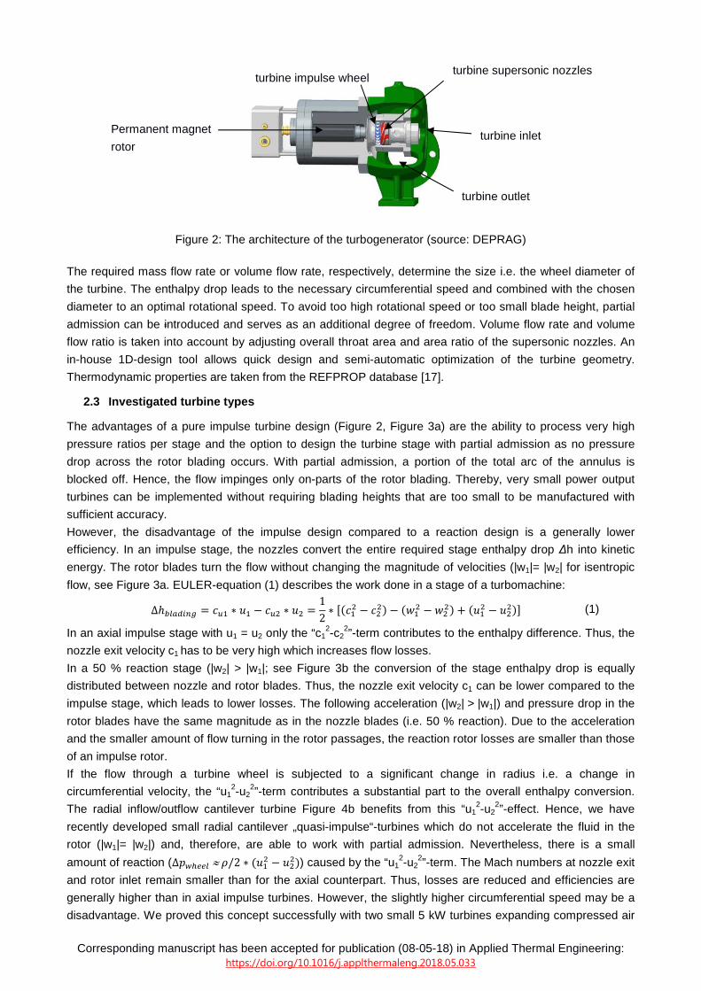
Figure 2: The architecture of the turbogenerator (source: DEPRAG)
The required mass flow rate or volume flow rate, respectively, determine the size i.e. the wheel diameter of
the turbine. The enthalpy drop leads to the necessary circumferential speed and combined with the chosen
diameter to an optimal rotational speed. To avoid too high rotational speed or too small blade height, partial
admission can be introduced and serves as an additional degree of freedom. Volume flow rate and volume
flow ratio is taken into account by adjusting overall throat area and area ratio of the supersonic nozzles. An
in-house 1D-design tool allows quick design and semi-automatic optimization of the turbine geometry.
Thermodynamic properties are taken from the REFPROP database [17].
2.3 Investigated turbine types
The advantages of a pure impulse turbine design (Figure 2, Figure 3a) are the ability to process very high
pressure ratios per stage and the option to design the turbine stage with partial admission as no pressure
drop across the rotor blading occurs. With partial admission, a portion of the total arc of the annulus is
blocked off. Hence, the flow impinges only on-parts of the rotor blading. Thereby, very small power output
turbines can be implemented without requiring blading heights that are too small to be manufactured with
sufficient accuracy.
However, the disadvantage of the impulse design compared to a reaction design is a generally lower
efficiency. In an impulse stage, the nozzles convert the entire required stage enthalpy drop ∆h into kinetic
energy. The rotor blades turn the flow without changing the magnitude of velocities (|w1|= |w2| for isentropic
flow, see Figure 3a. EULER-equation (1) describes the work done in a stage of a turbomachine:
∆ℎ������ = �� ∗ � − ��� ∗ �� =
12∗ ��� � − ���� − ��
� − ���� + ��
� − ����� (1)
In an axial impulse stage with u1 = u2 only the “c12-c2
2”-term contributes to the enthalpy difference. Thus, the
nozzle exit velocity c1 has to be very high which increases flow losses.
In a 50 % reaction stage (|w2| > |w1|; see Figure 3b the conversion of the stage enthalpy drop is equally
distributed between nozzle and rotor blades. Thus, the nozzle exit velocity c1 can be lower compared to the
impulse stage, which leads to lower losses. The following acceleration (|w2| > |w1|) and pressure drop in the
rotor blades have the same magnitude as in the nozzle blades (i.e. 50 % reaction). Due to the acceleration
and the smaller amount of flow turning in the rotor passages, the reaction rotor losses are smaller than those
of an impulse rotor.
If the flow through a turbine wheel is subjected to a significant change in radius i.e. a change in
circumferential velocity, the “u12-u2
2”-term contributes a substantial part to the overall enthalpy conversion.
The radial inflow/outflow cantilever turbine Figure 4b benefits from this “u12-u2
2”-effect. Hence, we have
recently developed small radial cantilever „quasi-impulse“-turbines which do not accelerate the fluid in the
rotor (|w1|= |w2|) and, therefore, are able to work with partial admission. Nevertheless, there is a small
amount of reaction (∆������ ≈�/2 ∗ �� � − ��
��) caused by the “u12-u2
2”-term. The Mach numbers at nozzle exit
and rotor inlet remain smaller than for the axial counterpart. Thus, losses are reduced and efficiencies are
generally higher than in axial impulse turbines. However, the slightly higher circumferential speed may be a
disadvantage. We proved this concept successfully with two small 5 kW turbines expanding compressed air
Permanent magnet
rotor
turbine impulse wheel turbine supersonic nozzles
turbine inlet
turbine outlet
Corresponding manuscript has been accepted for publication (08-05-18) in Applied Thermal Engineering: https://doi.org/10.1016/j.applthermaleng.2018.05.033
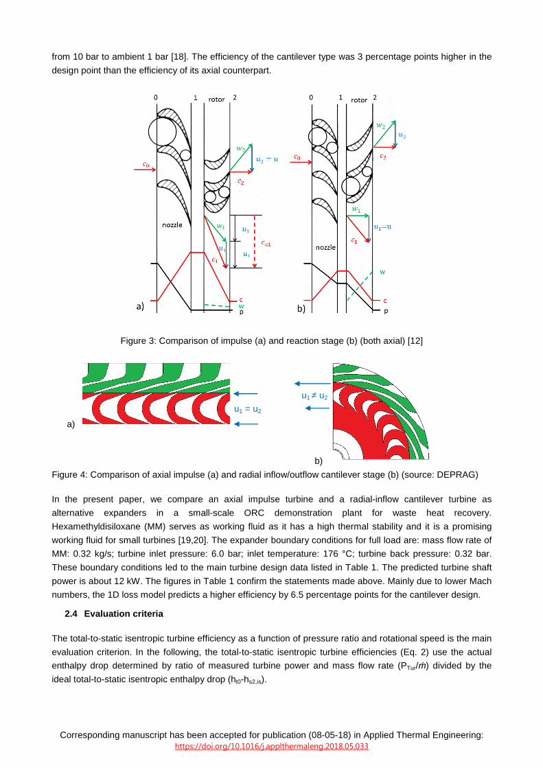
from 10 bar to ambient 1 bar [18]. The efficiency of the cantilever type was 3 percentage points higher in the
design point than the efficiency of its axial counterpart.
Figure 3: Comparison of impulse (a) and reaction stage (b) (both axial) [12]
a)
b)
Figure 4: Comparison of axial impulse (a) and radial inflow/outflow cantilever stage (b) (source: DEPRAG)
In the present paper, we compare an axial impulse turbine and a radial-inflow cantilever turbine as
alternative expanders in a small-scale ORC demonstration plant for waste heat recovery.
Hexamethyldisiloxane (MM) serves as working fluid as it has a high thermal stability and it is a promising
working fluid for small turbines [19,20]. The expander boundary conditions for full load are: mass flow rate of
MM: 0.32 kg/s; turbine inlet pressure: 6.0 bar; inlet temperature: 176 °C; turbine back pressure: 0.32 bar.
These boundary conditions led to the main turbine design data listed in Table 1. The predicted turbine shaft
power is about 12 kW. The figures in Table 1 confirm the statements made above. Mainly due to lower Mach
numbers, the 1D loss model predicts a higher efficiency by 6.5 percentage points for the cantilever design.
2.4 Evaluation criteria
The total-to-static isentropic turbine efficiency as a function of pressure ratio and rotational speed is the main
evaluation criterion. In the following, the total-to-static isentropic turbine efficiencies (Eq. 2) use the actual
enthalpy drop determined by ratio of measured turbine power and mass flow rate (PTur/ṁ) divided by the
ideal total-to-static isentropic enthalpy drop (ht0-hs2,is).
u1 = u2
u1 ≠ u2

Corresponding manuscript has been accepted for publication (08-05-18) in Applied Thermal Engineering: https://doi.org/10.1016/j.applthermaleng.2018.05.033
!�",$" =
%&'()*+
�,-.�/0,1/=
%23�423∗)* �+
�,-.�/0,1/ (2)
The term (ht0-hs2,is) is calculated with REFPROP [17] based on the measured inlet temperature and pressure
and the outlet pressure. The actual turbine power is calculated using the electric power Pel determined by the
feed-in unit and the overall electrical efficiency (ηel) of the entire electrical conversion chain (details can be
found elsewhere [15]). Based on this approach, the isentropic efficiency just depends on the pressure and
temperature at turbine inlet (to calculate ht0) and the pressure at turbine outlet (to calculate hs2,is). Therefore,
the temperature at the outlet of the turbine is not taken into account. This is a main advantage of the
approach via the power of the feed-in unit as commonly known (see for example [21,22]) conjugate heat
transfer does not influence the isentropic efficiency if it is calculated with equation (2). Furthermore, we
compared both approaches (theoretical thermodynamic calculation and calculation based on equation (2))
and found the deviation of both approaches for full load to be less than 2 %. The deviation can be caused by
conjugate heat transfer or by uncertainties in fluid properties, which is already discussed by Heberle and
Brüggemann [23].
The mass flow rate is measured by a Coriolis device. Note that the pressure and temperatures sensors are
installed upstream and downstream of the turbine casing flange. Hence, total-to-static turbine efficiencies
(Eq. (2)) include flow losses occurring in the inlet and outlet casing.
Next to the efficiency, the required swallowing capacity is an important parameter for ORC operation. That
means that the turbine must generate the design inlet pressure for the required mass flow rate and inlet
temperature. Otherwise, the operating point of the ORC would deviate from its design point. The swallowing
capacity of a turbine is described by the corrected mass flow rate 5* 6788 (Eq. 3) in turbomachinery
development:
9* :;<< =9* ∗ =>$,��
�$,�� (3)
For an ideal gas flowing through a choking nozzle, 9* :;<< keeps constant as long as the nozzle remains
choked. This means that the turbine inlet pressure is proportional to the mass flow rate and independent
from turbine back pressure. This turbine operational behavior determines the operational behavior of the
entire ORC plant
Table 1: Turbine main design data
a) the specific speed is defined as: ?" =�∙A∙�BC
∙ D* -.F
∆�,/,1/-.GF
axial impulse turbine radial cantilever turbine
wheel diameter D mm 120
rotational speed n rpm 24,000 28,000
specific speeda)
ns - 0.31 0.35
degree of admission ε % 100 100
pressure ratio PR (ts) - 18.75
volume flow ratio Vr 22.3
degree of reaction r % 0 13
nozzle exit Mach number M1 - 2.11 1.98
rotor relative inlet Mach number Mr1 - 1.14 0.87
expected shaft power kW 12-13 predicted total-to-static isentropic
efficiency (1D loss model) ηts % 68.0 74.5

Corresponding manuscript has been accepted for publication (08-05-18) in Applied Thermal Engineering: https://doi.org/10.1016/j.applthermaleng.2018.05.033
3. Results
3.1 ORC test bed
As we have already stated in the introduction, our main interest is the characterization of the different turbine
types. Hence, the most important parameters of the ORC test bed are the turbine inlet and outlet pressure as
well as the mass flow rate in the ORC. The measurement of an exemplary operational point for the axial
turbine at 6 bar clearly indicates that the conditions for the analysis are constant for more than ten minutes
(see Figure 5). Due to the stable conditions for more than 10 minutes, we can exclude cooling down or
heating up of turbine parts and the distortion of measurement results by those effects. Table 2 gives a
summary of the measurement campaign.
Figure 5: Pressure levels and mass flow rate during operation of the axial turbine
Table 2: Main data of final measurement campaigns
3.2 Axial turbine
Figure 6 depicts the total-to-static isentropic efficiency depending on rotational speed for different total-to-
static pressure ratios (PR). For the axial turbine, pressure ratio was only changed by inlet pressure (i.e. m_dot
= mass flow rate) while outlet pressure was almost constant (≈ 0.3 bar).
axial impulse turbine radial cantilever turbine
turbine inlet pressure bar 3.2 – 6.3 3.2 – 6.3
turbine inlet temperature °C 167.1 – 182.7 163.5 – 185.5
turbine outlet pressure bar 0.26 – 0.33 0.17 – 0.37
mass flow rate kg/s 0.16 - 0.33 0.17 – 0.32
rotational speed n 18,000 – 26,000 20,000 – 30,000
turbine power kW 5.6 - 14.1 5.1 – 16.0

Corresponding manuscript has been accepted for publication (08-05-18) in Applied Thermal Engineering: https://doi.org/10.1016/j.applthermaleng.2018.05.033
Figure 6: Axial turbine characteristics, total-to-static isentropic efficiency as function of rotational speed
The characteristics at design point (24,000 rpm, PR = 18.8) show a flat maximum (73.4 %; solid black line).
The curves for PR = 15.3, PR = 17.4 and PR = 18.8 show similar shapes whereas the rotational speed for
maximum efficiency varies slightly between 23,000 rpm and 24,000 rpm. However, the course for the lowest
pressure ratio (PR = 12.6) is not reasonable. The measured points at 22,000 rpm and 23,000 rpm show a
sudden drop in measured power by about 250 W (on a level of 5000 W). Most likely, these outliers are
caused by the lubrication system, which injects a certain amount of lubricant from time to time. For PR = 12.6
this effect is obvious due to the low absolute power, for higher PR the effect becomes negligible.
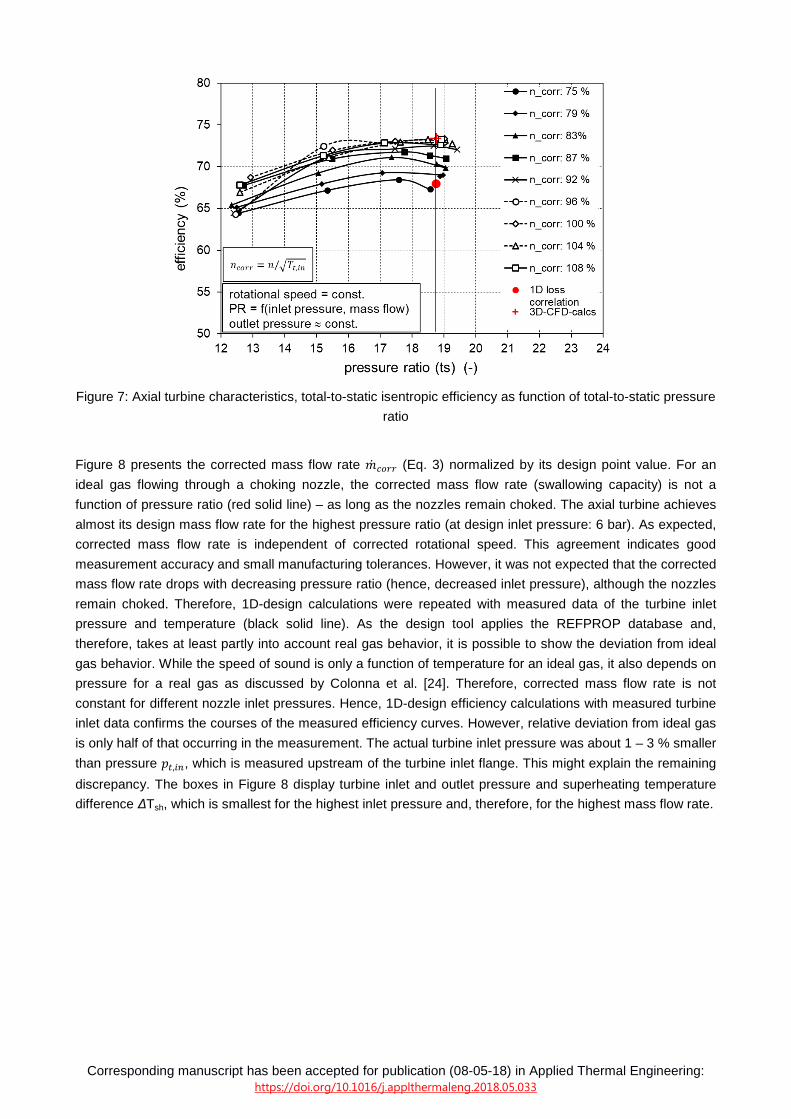
In Figure 7, the dependency between efficiency and total-to-static pressure ratio is analyzed. The corrected
rotational speed, normalized by its design point value, serves as parameter (?:;<< = ?/=>$,��). The curves
show similar behavior, except ncorr = 92 % and ncorr = 96 %. The different shape is caused by the data points
at lowest pressure ratio (PR ≈ 12.6). These data points correspond to the measurements at 3.2 bar inlet
pressure and 22,000 rpm as well as 23,000 rpm. As mentioned before, these two points seem to be outliers.
The design pressure ratio of the Laval nozzles is PRnozzle,design = 18.75 for the axial turbine. The maximum
efficiency occurs at this pressure ratio for ncorr > 90 %. The maximum is rather flat i.e. the nozzles seem to
react insensitively on changes in pressure ratio. It might be possible that the increasing losses in the nozzle
at off design (PRnozzle < PRnozzle,design) are partly compensated by reduced losses in rotor blading due to the
smaller rotor relative inlet Mach number.
If we compare the measured data with theoretical calculations, we notice that the design efficiency (1D-loss-
correlation) is 68.0 % whereas the efficiency determined by 3D CFD calculations (3D_CFD_Calcs; model
without shroud leakage, disk friction and bearing losses) is 73.4 %. Hence, both simulation approaches were
too pessimistic – especially the 1D loss model which was used for the design of the turbine.
Corresponding manuscript has been accepted for publication (08-05-18) in Applied Thermal Engineering: https://doi.org/10.1016/j.applthermaleng.2018.05.033
Figure 7: Axial turbine characteristics, total-to-static isentropic efficiency as function of total-to-static pressure
ratio
Figure 8 presents the corrected mass flow rate 9* :;<< (Eq. 3) normalized by its design point value. For an
ideal gas flowing through a choking nozzle, the corrected mass flow rate (swallowing capacity) is not a
function of pressure ratio (red solid line) – as long as the nozzles remain choked. The axial turbine achieves
almost its design mass flow rate for the highest pressure ratio (at design inlet pressure: 6 bar). As expected,
corrected mass flow rate is independent of corrected rotational speed. This agreement indicates good
measurement accuracy and small manufacturing tolerances. However, it was not expected that the corrected
mass flow rate drops with decreasing pressure ratio (hence, decreased inlet pressure), although the nozzles
remain choked. Therefore, 1D-design calculations were repeated with measured data of the turbine inlet
pressure and temperature (black solid line). As the design tool applies the REFPROP database and,
therefore, takes at least partly into account real gas behavior, it is possible to show the deviation from ideal
gas behavior. While the speed of sound is only a function of temperature for an ideal gas, it also depends on
pressure for a real gas as discussed by Colonna et al. [24]. Therefore, corrected mass flow rate is not
constant for different nozzle inlet pressures. Hence, 1D-design efficiency calculations with measured turbine
inlet data confirms the courses of the measured efficiency curves. However, relative deviation from ideal gas
is only half of that occurring in the measurement. The actual turbine inlet pressure was about 1 – 3 % smaller
than pressure �$,��, which is measured upstream of the turbine inlet flange. This might explain the remaining
discrepancy. The boxes in Figure 8 display turbine inlet and outlet pressure and superheating temperature
difference ∆Tsh, which is smallest for the highest inlet pressure and, therefore, for the highest mass flow rate.

Corresponding manuscript has been accepted for publication (08-05-18) in Applied Thermal Engineering: https://doi.org/10.1016/j.applthermaleng.2018.05.033
Figure 8: Normalized corrected mass flow rate (swallowing capacity) as a function of pressure ratio (red
horizontal line indicates design value or ideal gas flowing through a choking nozzle, respectively)
3.3 Cantilever turbine
Figure 9 shows the efficiency characteristics of the cantilever turbine for two different outlet pressures. Solid
lines represent an outlet pressure of about 0.3 bar ≈ const, dashed lines represent an outlet pressure of
about 0.2 bar ≈ const. Therefore, pressure ratios (PR) are about 1.5 times higher for the dashed lines than
for the solid lines at comparable mass flow rates (m_dot).
Figure 9: Cantilever turbine characteristics, total-to-static isentropic efficiency as function of rotational speed
The red solid line (large crosses) is closest to design data at condenser pressure 0.3 bar. The mass flow rate
is 100 %, the pressure ratio PR = 18.3. The cantilever turbine shows a flat maximum of 73.4 % at a rotational
speed of 25,000 rpm, which is lower than the design point (28,000 rpm). The efficiency peak moves to higher
rotational speed with increasing pressure ratio (PR). This is not surprising keeping in mind that the
intermediate pressure between radial nozzles and wheel (ps1, Eq. 4 ) and, therefore, the nozzle pressure ratio
(PRnozzle, Eq. 5) is a function of rotational speed (∆������ ≈H
�∗ �u � − ��
��~?�).

Corresponding manuscript has been accepted for publication (08-05-18) in Applied Thermal Engineering: https://doi.org/10.1016/j.applthermaleng.2018.05.033
ps1 = ps2 + ∆pwheel (4)
PRnozzle = PR/ PRwheel = pt0/ps2*ps2/ps1 = pt0/ps1 (5)
We can conclude that the design pressure ratio of the cantilever turbine nozzles (PRnozzle,design = 13.0) can be
achieved over a wide range of overall turbine pressure ratio (PR) as long as the rotational speed (n) is
adjusted. The cantilever turbine achieves the highest measured efficiency of about 76.8 % for PR = 22.4 and
rotational speed n = 27,000 rpm. Most likely, the nozzles work with their design pressure ratio in this
operation point.
Similar to Figure 7 for the axial turbine, Figure 10 displays efficiency against total-to-static pressure ratio for
the cantilever turbine. For the cantilever turbine (Figure 10), the range of investigated pressure ratios is wider
than for the axial turbine (Figure 7), because two different condenser pressures (0.2 bar and 0.3 bar) could
be achieved at two different measuring days. It is obvious, that the shape of the curves varies significantly
with corrected rotational speed. This is caused by the intermediate pressure between radial nozzles and
wheel, which increases with rotational speed as already explained.
Figure 10: Cantilever turbine characteristics, total-to-static isentropic efficiency as function of total-to-static
pressure ratio
Nozzle pressure ratio (Eq. 4, 5) and degree of reaction vary with rotational speed. For any rotational speed,
an overall turbine pressure ratio PR exists, for which the nozzles work with their design pressure ratio
PRnozzle,design i.e. with optimum nozzle efficiency. No matter whether the overall pressure ratio is reduced or
increased, the overall efficiency drops when deviating from this operation point. Accordingly, in the
investigated pressure ratio range 12 < PRturbine < 24 three different parts of the typical efficiency characteristic
for ncorr = const. are shown: the ascending part, the region close to maximum and the descending part.
Figure 11 depicts the corrected mass flow rate as function of pressure ratio. Again, two sets of curves due to
the different condenser pressures at different measuring days (see boxes) are shown. The findings and
explanations for the axial turbine (Figure 8) are valid for the cantilever turbine as well. Furthermore, it is
obvious that the corrected mass flow rate is independent of turbine back pressure as we find same figures
for different condenser pressures but similar inlet pressures. For turbines with choking nozzles this in an

Corresponding manuscript has been accepted for publication (08-05-18) in Applied Thermal Engineering: https://doi.org/10.1016/j.applthermaleng.2018.05.033
expected behavior. Superheating temperature difference ∆Tsh is only 2 K for 6 bar inlet pressure, 0.33 bar
outlet pressure and 100 % mass flow rate. As the inlet temperature is measured upstream of the turbine inlet
flange, the vapor might be slightly wet in this operational point.
Figure 11: Normalized corrected mass flow rate (swallowing capacity) as a function of pressure ratio (red
horizontal line indicates design value or ideal gas flowing through a choking nozzle, respectively)
4. Discussion
4.1 Comparison of turbine types
The achieved design point efficiency of 73.4 % (total-to-static) for the 12 kW axial impulse turbine is a
reasonable figure, keeping in mind the small size of the turbine in combination with the high pressure ratio
which it must process. The total-to-total isentropic efficiency is about 4 % higher (based on design
calculation). The efficiency characteristics are almost constant over a wide range of pressure ratios Figure 7
and, furthermore, show a rather flat maximum over rotational speed Figure 6. Both qualities are very
valuable for a micro-turbine-generators applied in small waste heat recovery plants, which are mostly
characterized by fluctuating heat fluxes.
As predicted, the cantilever competitor achieves even a higher efficiency of 76.8 %, which is an excellent
figure for a turbine of this power size. However, the figure is achieved for a pressure ratio of PR = 22.4,
which is well above the design value of (PR design = 18.75). Hence, our design process worked well for the
axial turbine but failed somehow in meeting the design point of the cantilever turbine. The efficiency
characteristics of the cantilever turbine show a strong dependency on rotational speed (Figure 9, Figure 10).
This behavior was expected as the intermediate pressure between nozzles and wheel and, therefore, the
nozzle pressure ratio is a function of rotational speed. Hence, an active speed control is necessary for
efficient ORC plant operation. If such a speed control is available, it might be an advantage for the cantilever
turbine. This is clearly shown in Figure 12, in which all data points of Figure 7 and Figure 10 with maximum
efficiency for a certain pressure ratio are displayed to compare the axial turbine (dashed line) and the radial
cantilever turbine (solid line). Figure 12 also includes some additional data points at lower and higher
pressure ratios which are not included in Figure 7 and Figure 10.

Corresponding manuscript has been accepted for publication (08-05-18) in Applied Thermal Engineering: https://doi.org/10.1016/j.applthermaleng.2018.05.033
Figure 12: Efficiency envelopes over pressure ratio for the axial impulse and the radial cantilever turbine
The necessary rotational speed for the axial turbines varies between 22,000 and 24,000 rpm. The total-to-
static isentropic efficiency is almost constant across a wide range of pressure ratios (16 ≤ PR ≤ 22). For
PR <14 efficiency decreases steeply. Probably, compression shocks in the convergent-divergent nozzles
occur. Note that the nozzles are designed for PRnozzle,design = 18.75 (axial turbine).
For the radial cantilever turbine, the necessary rotational speed varies between 23,000 and 27,000 rpm. As
mentioned before, the cantilever turbine fails in surpassing the axial design in the region of design pressure
ratio (PR = 18.75) probably due to the design procedure. Furthermore, a local minimum in efficiency occurs
just at design pressure ratio. We state that probably the low superheating of the vapor (∆Tsh = 2 K) at design
pressure ratio (highest mass flow rate) for the cantilever turbine causes this behavior. If the nozzles of the
cantilever turbine were fed by slightly wet vapor, droplets would not participate in the expansion process.
Furthermore, they would cause additional losses. Hence, a small amount of wetness could explain this
efficiency minimum.
For PR ≥ 20 the cantilever turbine surpasses its axial counterpart. Its maximum efficiency is 3.4 percentage
points higher than that of the axial turbine (76.8 % compared to 73.4 %). A similar benefit was measured in a
former experimental comparison carried out with two air driven turbines [18]. However, the measured
advantage of the cantilever design (3.4 percentage points) is significantly lower than the predicted one
(6.5 percentage points, see Table 1). One has to keep in mind that the investigated cantilever turbine is just
the second of its type designed. Thus, we are convinced that it will be possible to put a higher portion of the
theoretical advantage into practice. A finding of these measurements, which was not expected, is that by
varying the rotational speed, the cantilever turbine can keep its high level of efficiency even for PR far below
design pressure ratio. This might be a very valuable characteristic of this turbine design applied in our MTG-
c-kit.
Although this paper focuses on the thermodynamic behaviour of micro-turbines, we want to give at least a
rough figure about the cost of our turbines so that the efficiency of the turbines can be coupled with
investment costs in the future. Generally, a cost model for such turbines has already been given in one of
our previous theoretical studies [5]. By now, the turbine manufacturer of our turbine (DEPRAG SCHULZ
GMBH u. CO) states that costs are about 1000 €/kW. However, this figure still depends on the number of
turbines ordered.
4.2 Comparison to other turbine papers

Corresponding manuscript has been accepted for publication (08-05-18) in Applied Thermal Engineering: https://doi.org/10.1016/j.applthermaleng.2018.05.033
Although experimental data of small ORC turbines (< 100 kW) are rare in literature compared to simulation
results, Table 3 lists the few available studies on the topic. As can be seen, work on small scale turbines
have has been intensified in recent years. However, the studies only present design point efficiencies and do
not contain off-design characteristics.
Table 3: Experimental data of small turbines
Reference Working fluid Turbine Type PR Power Isentropic efficiency
Gazet et al. [3] HFE Single stage axial impulse 3 10.0 kW 70.0 %
Kaczmarczyk et al. [25]
HFE7100 4 stage radial 7 2.0 kW 70.0 %
Kang et al. [26] R245fa Radial inflow 4.1 32.7 kW 78.7 %
Klonowicz et al. [27]
R227ea Single stage axial impulse
11 % partial admission 2.9 10.1 kW 59.0 %
Kryllowicz et al. [28] HFE7100 Single stage axial impulse 3.5 12.1 kW 67.0 %
Shao et al. [29] R123 Radial inflow 3.0 3.4 kW 83.6 %
Seume et al. [10] Ethanol Single stage axial impulse,
40 % partial admission 50 8.0 kW 58.0 %
Verneau [30] FC75 Single stage axial impulse 50 40.0 kW 75.0 %
Similar to us, most researchers prefer a single stage axial turbine even for very high pressure ratios. The
efficiencies for the two bigger machines (32.7 kW/40 kW) are in the range of the presented 12 kW impulse
and cantilever turbine. The newly introduced turbines are about 10 percentage points more efficient than
their competitors in the comparable power class of around 10 kW. Of course, turbines pressure ratios must
be taken into account, which is significantly lower for Kaczmarczyk´s machine but far higher for Seume´s
small turbine which additionally suffers from partial admission losses. Tuurunen-Saaresti et al. [9] report a
10 kW radial turbine working with octamethyltrisiloxane (MDM). It is designed for a very high pressure ratio of
about PR ≈ 113. Unfortunately, they haven´t achieved design point operation yet and don´t mention turbine
efficiency in their paper.
4.3 Comparison to volumetric expanders
Small scroll, vane or screw expanders have the advantage of low investment costs, as they are available
from refrigeration or compressed air technology in which they act as compressors. Therefore, these
expanders have often been applied in small-scale ORC plants. Nevertheless, rather few publications with
experimental investigations are available (Table 4). It is obvious that the volumetric expanders are applied
for the power range significantly below 10 kW and rather small pressure ratios (single stage). The latter limits
their application to low temperature ORCs. In this case, they are competitive to the turbines presented in our
study. For higher pressure ratios (PR >10) and bigger sizes (P > 10kW) turbines in general and the
introduced turbines in particular are superior. This fits well to the analysis of Branchini et al. [8] who noticed
that also in field applications volumetric expanders are hardly found at the higher power range.
5. Conclusion
In our paper, we state that micro-turbines are efficient expanders for small ORC plants in waste heat
recovery. Our measured data at design point for an axial impulse turbine and a radial cantilever turbine verify
this statement. Furthermore, part-load behaviour is presented with respect to mass flow rate (50 % to 100
%), corrected rotational speed (75 % to 108 %) and pressure ratio (10 to 24). Total-to-static isentropic
efficiencies of more than 70 % have been achieved over a wide range of operating conditions for both
turbine types, whereas the cantilever turbine is generally more efficient than its axial impulse counterpart is.
For an efficient part-load operation, the cantilever turbine needs a controllable rotational speed, whereas the
efficiency of the axial turbine depends less on rotational speed. For applications in waste heat recovery and,

Corresponding manuscript has been accepted for publication (08-05-18) in Applied Thermal Engineering: https://doi.org/10.1016/j.applthermaleng.2018.05.033
therefore, for fluctuating heat fluxes, these results give valuable information about the correct choice of the
expander type. We hope that our results for the efficiency and the swallowing capacity at off-design
conditions will help the ORC community to improve simulation studies and ORC design compared to
commonly applied constant isentropic efficiencies. Furthermore, we state that the micro-turbine-generator-
construction-kit and the results of our publication may lead to more economic solutions for ORC expanders
as the approach make use of economy of volume and economy of scale.
Table 4: Experimental data of small volumetric expanders
Reference Working fluid Expander Type PR Power Isentropic efficiency
Aoun and Clodic [31]
Water Scroll 3.8 0.45 kW 48 %
Daccord et al. [32]
Water Piston expander 50 3.0 kW 54 %
Declaye et al. [33]
R245fa Open-drive scroll expander ≈ 4.5 2.1 kW 75.7 %
Qiu et al. [34] Compressed
air Vane-type air expander ≈ 6.7 0.85 W 26 %
Harada [35] R245fa Refrigeration scroll
expander with direct shaft connection
≤ 7 1.0 kW 87 %
He et al. [36] Compressed
Air Single-screw expander ≈ 15 22.0 kW 55 %
Lemort & Quoilin [37]
HCFC-123 Scroll 5.3 1.8 kW 67 %
Lemort et al. [7] R245fa Hermetic refrigeration scroll
machine ≤ 6 2.2 kW 68 %
Ntavou et al. [38] R245fa Two stage scroll 10 2.9 kW 70 %
Oudkerk et al. [39]
R245fa Swash-plate piston
expander ≤ 11 2.0 kW 53 %
Wang et al. [40] R134a Scroll 4.8 0.62 kW 70 %
Wu et al. [41] R123 Single scroll expander 3.9 1.5 kW 86 %
Wang et al. [42] Compressed
air Single screw expander ≈ 6 5.0 kW 30.8 %
Acknowledgments: From 2014 and 2016 the project was partly funded by the Bavarian State Ministry of
Education and Culture, Science and Art within the framework “Competence Center Heat and Power
Systems”. The authors highly appreciated this funding.
Conflicts of Interest: The authors declare the following competing financial interest(s). Andreas P. Weiß,
Tobias Popp, Jonas Müller, Markus Preißinger and Dieter Brüggemann declare no competing financial
interests. Josef Hauer is employee in the R&D department of DEPRAG SCHULZ GMBH u. CO, the
company, which commercially distributes the investigated turbines.
Nomenclature
c absolute velocity
h enthalpy
9* mass flow rate
n rotational speed
ns specific speed
p pressure

Corresponding manuscript has been accepted for publication (08-05-18) in Applied Thermal Engineering: https://doi.org/10.1016/j.applthermaleng.2018.05.033
T temperature
u circumferential velocity
w relative velocity
∆ difference
Abbreviations
1D one dimensional
3D three dimensional
CFD computational fluid dynamics
MTG-c-kit micro-turbine-generator-construction-kit
TGU turbine-generator-unit
Subscripts
0 nozzle blading/stage inlet
1 nozzle blading outlet, rotor blading inlet
2 rotor blading/stage outlet
corr corrected
in inlet
is isentropic
DP design point
el electrical
sh superheated
t total
ts total-to-static
References
[1] M. Pehnt, J. Bödeker, M. Arens, E. Jochem, F. Idrissova, Die Nutzung industrieller Abwärme - technisch-wirtschaftliche Potenziale und energiepolitische Umsetzung, Institut für Energie- und Umweltforschung Heidelberg, Heidelberg, Karlsruhe, Germany, 2013.
[2] F. Campana, M. Bianchi, L. Branchini, A. De Pascale, A. Peretto, M. Baresi, A. Fermi, N. Rossetti, R. Vescovo, ORC waste heat recovery in European energy intensive industries: Energy and GHG savings, Energy Conversion and Management. 76 (2013) 244–252. doi:10.1016/j.enconman.2013.07.041.
[3] C. Gazet, A. Leroux, B. Paillette, A. Pauchet, Operational experience on ORC unse for waste heat valorization in biogas power plant, in: Proceedings of the 3rd International Seminar on ORC Power Systems, University of Liège and Ghent University, Brussels, Belgium, 2015.
[4] D. Gewald, K. Rostek, A. Schuster, R. Amann, From technology deevlopment to (pre-series) product - the EPACK HYBRID, in: Proceedings of the 3rd International Seminar on ORC Power Systems, University of Liège and Ghent University, Brussels, Belgium, 2015.
[5] M. Preißinger, D. Brüggemann, Thermoeconomic Evaluation of Modular Organic Rankine Cycles for Waste Heat Recovery over a Broad Range of Heat Source Temperatures and Capacities, Energies. 10 (2017) 269. doi:10.3390/en10030269.
[6] Y. Glavatskaya, P. Podevin, V. Lemort, O. Shonda, G. Descombes, Reciprocating Expander for an Exhaust Heat Recovery Rankine Cycle for a Passenger Car Application, Energies. 5 (2012) 1751–1765. doi:10.3390/en5061751.
[7] V. Lemort, G. Ludovic, L. Arnaud, S. Declaye, S. Quoilin, A comparison of piston, screw an scroll expander for small Rankine cycle systems, in: Proceedings of the 3rd International Conference on Microgeneration and Related Technologies, Naples, Italy, 2013.
[8] L. Branchini, A. De Pascale, A. Peretto, Systematic comparison of ORC configurations by means of comprehensive performance indexes, Applied Thermal Engineering. 61 (2013) 129–140. doi:10.1016/j.applthermaleng.2013.07.039.
Corresponding manuscript has been accepted for publication (08-05-18) in Applied Thermal Engineering: https://doi.org/10.1016/j.applthermaleng.2018.05.033
[9] T. Turunen-Saaresti, A. Uusitalo, J. Honkatukia, Design and testing of high temperature micro-ORC test stand using Siloxane as working fluid, Journal of Physics: Conference Series. 821 (2017) 012024. doi:10.1088/1742-6596/821/1/012024.
[10] J.R. Seume, M. Peters, H. Kunte, Design and test of a 10kW ORC supersonic turbine generator, Journal of Physics: Conference Series. 821 (2017) 012023. doi:10.1088/1742-6596/821/1/012023.
[11] G. Qiu, H. Liu, S. Riffat, Expanders for micro-CHP systems with organic Rankine cycle, Applied Thermal Engineering. 31 (2011) 3301–3307. doi:10.1016/j.applthermaleng.2011.06.008.
[12] A.P. Weiß, Volumetric Expander Versus Turbine - Which is the better Choice for Small ORC Plants?, in: Proceedings of the 3rd International Seminar on ORC Power Systems, University of Liège and Ghent University, Brussels, Belgium, 2015.
[13] J. Bao, L. Zhao, A review of working fluid and expander selections for organic Rankine cycle, Renewable and Sustainable Energy Reviews. 24 (2013) 325–342. doi:10.1016/j.rser.2013.03.040.
[14] S. Quoilin, S. Declaye, A. Legros, L. Guillaume, V. Lemort, Working fluid selection and operating maps for Organic Rankine Cycle expansion machines, in: International Compressor Engineering Conference, Purdue, 2012: p. Paper 1546. http://doc s.lib.purdue.edu/icec/1925.
[15] A. Weiß P., J. Hauer, T. Popp, M. Preißinger, Experimental investigation of a supersonic micro turbine running with hexamethyldisiloxane, in: 2017: p. 020050. doi:10.1063/1.5004384.
[16] G. Verdonk, T. Dufornet, Development of a Supersonic Steam Turbine with a Single Stage Pressure Ratio of 200 for Generator and Mechanical Drive, in: Lecture Series 1987-07, von Karman Institute for Fluid Mechanics, Brussels, Belgium, 1987.
[17] E. Lemmon, M. Huber, McLinden, NIST Standard Reference Database 23: Reference Fluid Thermodynamic and Transport Properties-REFPROP, National Institute of Standards and Technology, Gaithersburg, 2010.
[18] A.P. Weiß, G. Zinn, Micro Turbine Generators for Waste Heat Recovery And Compressed Air Energy Storage, in: 15th Conference on Power System Engineering - ES2016, Pilsen, Czech Republic, 2016.
[19] M. Preißinger, D. Brüggemann, Thermal Stability of Hexamethyldisiloxane (MM) for High-Temperature Organic Rankine Cycle (ORC), Energies. 9 (2016) 183. doi:10.3390/en9030183.
[20] M. Preißinger, J.A.H. Schwöbel, A. Klamt, D. Brüggemann, Multi-criteria evaluation of several million working fluids for waste heat recovery by means of Organic Rankine Cycle in passenger cars and heavy-duty trucks, Applied Energy. 206 (2017) 887–899. doi:10.1016/j.apenergy.2017.08.212.
[21] R. Mathie, H. Nakamura, C.N. Markides, Heat transfer augmentation in unsteady conjugate thermal systems – Part II: Applications, International Journal of Heat and Mass Transfer. 56 (2013) 819–833. doi:10.1016/j.ijheatmasstransfer.2012.09.017.
[22] Y.B. Zudin, Analysis of the processes of heat transfer with periodic intensity with allowance for temperature fluctuations in the heat carrier, Journal of Engineering Physics and Thermophysics. 73 (2000) 243–247. doi:10.1007/BF02681724.
[23] F. Heberle, D. Brüggemann, Thermo-Economic Evaluation of Organic Rankine Cycles for Geothermal Power Generation Using Zeotropic Mixtures, Energies. 8 (2015) 2097–2124. doi:10.3390/en8032097.
[24] P. Colonna, J. Harinck, S. Rebay, A. Guardone, Real-Gas Effects in Organic Rankine Cycle Turbine Nozzles, Journal of Propulsion and Power. 24 (2008) 282–294. doi:10.2514/1.29718.
[25] T.Z. Kaczmarcczyk, G. Zwica, E. Ihnatowicz, Experimental investigation of a radial micro turbine in Organic Rankine Cycle sytem with HFE7100 as working fluid, in: Proceedings of the 3rd International Seminar on ORC Power Systems, University of Liège and Ghent University, Brussels, Belgium, 2015.
[26] S.H. Kang, D.H. Chung, Design and Experimental Study of Organic Rankine Cycle (ORC) and Radial Turbine, in: ASME Turbo Expo 2011 Turbine Technical Conference and Exposition - Volume 3: Controls, Diagnostics and Instrumentation; Education; Electric Power; Microturbines and Small Turbomachinery; Solar Brayton and Rankine Cycle, ASME, 2011: pp. 1037–1043. doi:10.1115/GT2011-46152.
[27] P. Klonowicz, F. Heberle, M. Preißinger, D. Brüggemann, Significance of loss correlations in performance prediction of small scale, highly loaded turbine stages working in Organic Rankine Cycles, Energy. 72 (2014) 322–330.
[28] W. Kryllowicz, D. Piotrowska, L. Antczak, Concept of the geo-bio micro power plant, in: Proceedings of the 2nd International Seminar on ORC Power Systems, Rotterdam, The Netherlands, 2013.
[29] L. Shao, J. Zhu, X. Meng, X. Wei, X. Ma, Experimental study of an organic Rankine cycle system with radial inflow turbine and R123, Applied Thermal Engineering. 124 (2017) 940–947. doi:10.1016/j.applthermaleng.2017.06.042.
[30] A. Verneau, Supersonic turbines for Organic Rankine Cycles from 3 to 1300 kW: Small high pressure ratio turbines, in: Lecture Series 1987-07, von Karman Institute for Fluid Mechanics, Brussels, Belgium, 1987.
[31] B. Aoun, D. Clodic, Theoretical and experimental study on a croll vapor expander, in: International Compressor Engineering Conference, Purdue, 2008: p. Paper 1925. http://doc s.lib.purdue.edu/icec/1925.

Corresponding manuscript has been accepted for publication (08-05-18) in Applied Thermal Engineering: https://doi.org/10.1016/j.applthermaleng.2018.05.033
[32] R. Daccord, J. Melis, T. Kientz, A. Darmedru, R. Rireyre, N. Brisseau, E. Fonteneau, Exhaust Heat Recovery with Rankine piston expander, in: ICE Powertrain Electrification & Energy Recovery, Rueil-Malmaison, France, 2013.
[33] S. Declaye, S. Quoilin, L. Guillaume, V. Lemort, Experimental study on an open-drive scroll expander integrated into an ORC (Organic Rankine Cycle) system with R245fa as working fluid, Energy. 55 (2013) 173–183. doi:10.1016/j.energy.2013.04.003.
[34] G. Qiu, Y. Shao, J. Li, H. Liu, S.. B. Riffat, Experimental investigation of a biomass-fired ORC-based micro-CHP for domestic applications, Fuel. 96 (2012) 374–382. doi:10.1016/j.fuel.2012.01.028.
[35] J.K. Harada, Development on a small scale scroll expander, Master Thesis, Oregon State University, 2010.
[36] W. He, Y. Wu, Y. Peng, Y. Zhang, C. Ma, G. Ma, Influence of intake pressure on the performance of single screw expander working with compressed air, Applied Thermal Engineering. 51 (2013) 662–669. doi:10.1016/j.applthermaleng.2012.10.013.
[37] V. Lemort, S. Quoilin, C. Cuevas, J. Lebrun, Testing and modeling a scroll expander integrated into an Organic Rankine Cycle, Applied Thermal Engineering. 29 (2009) 3094–3102. doi:10.1016/j.applthermaleng.2009.04.013.
[38] E. Ntavou, G. Kosmadakis, D. Manolakos, G. Papadakis, D. Papantonis, Experimental Investigation of a Small-Scale Two Stage Organic Rankine Cycle Engine Operating at Low Temperature, in: Proceedings of the 3rd International Seminar on ORC Power Systems, University of Liège and Ghent University, Brussels, Belgium, 2015.
[39] J.F. Oudkerk, R. Dickes, O. Dumont, V. Lemort, Experimental performance of a piston expander in a small- scale organic Rankine cycle, IOP Conference Series: Materials Science and Engineering. 90 (2015) 012066. doi:10.1088/1757-899X/90/1/012066.
[40] H. Wang, R.B. Peterson, T. Herron, Experimental performance of a compliant scroll expander for an organic Rankine cycle, Proceedings of the Institution of Mechanical Engineers, Part A: Journal of Power and Energy. 223 (2009) 863–872. doi:10.1243/09576509JPE741.
[41] Z. Wu, D. Pan, N. Gao, T. Zhu, F. Xie, Experimental testing and numerical simulation of scroll expander in a small scale organic Rankine cycle system, Applied Thermal Engineering. 87 (2015) 529–537. doi:10.1016/j.applthermaleng.2015.05.040.
[42] W. Wang, Y. Wu, C. Ma, L. Liu, J. Yu, Preliminary experimental study of single screw expander prototype, Applied Thermal Engineering. 31 (2011) 3684–3688. doi:10.1016/j.applthermaleng.2011.01.019.