preparing custom shapes for esko studio
TRANSCRIPT
Preparing Custom Shapes for Esko Studio
Introduction This document document describes how to prepare 3D Collada files that can be used in Esko Studio.
These solutions require you to first prepare a Structural Design file (either .ARD or .ZAE), which describes the shape that you will apply artwork to. The same structural design files can also be used in other Esko 3D solutions, such as the 3D viewer in WebCenter.
These structural design files can be made in ArtiosCAD or the Studio Toolkits. That is the easiest and preferred approach for any folded structure (boxes, displays), standard flexible packaging (pillow bags, stand-up pouch, sachets) and rigid containers with labels or shrink sleeves. Other types of popular packaging shapes can also be downloaded from the online Shapes store.
Lastly, you can model your own packaging shapes in other 3D software, use them in Studio or WebCenter as structural design files and apply print to them. Thanks to this capability just about any packaging shape can be visualized. But such a structural design file needs to be properly prepared.
Collada is also the format of most of the items offered on Shapes, the online store of packaging resources. The Collada items on the Shapes store are prepared according to the guidelines in this document.
Pre-requisites Making shapes with ArtiosCAD or the purpose-made Studio Toolkits is an easy and a pleasant experience. But making a custom shape (one that is not possible to create with the Toolkits and not available on the Shapes store) is not easy. It is a technical and possibly labour-intensive process. But if you plan to use this shape repeatedly in Studio or WebCenter for different artwork variations, then it can be time well spent.
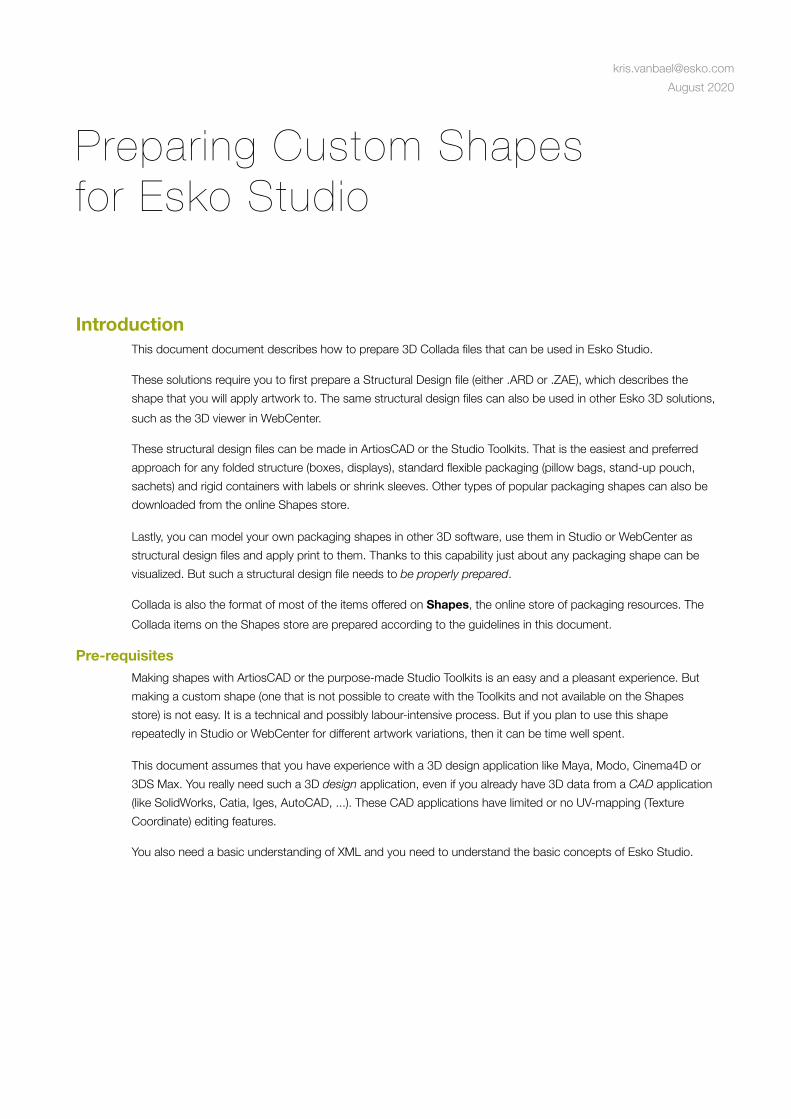
This document assumes that you have experience with a 3D design application like Maya, Modo, Cinema4D or 3DS Max. You really need such a 3D design application, even if you already have 3D data from a CAD application (like SolidWorks, Catia, Iges, AutoCAD, ...). These CAD applications have limited or no UV-mapping (Texture Coordinate) editing features.
You also need a basic understanding of XML and you need to understand the basic concepts of Esko Studio.
[email protected] August 2020

Workflow To prepare a custom shape for Studio, you need to run over the following tasks. The rest of the document will describe more details about these tasks.
1. Prepare your custom shape in your favorite 3D modeling software. • Make sure the model is suitable for real-time rendering. Adapt quality and complexity if needed. • Make sure the model includes the printable parts with proper UV-mapping • Make sure the other parts have a material definition that is compatible with Studio
2. Export to a Collada file 3. Identify the printable part in the XML code 4. Pack the collada file into a collada archive 5. Prepare a template for the artwork designers
About Collada For the custom 3D shapes, we have chosen for the Collada file format. Collada is an open and public file format, originally developed by Sony but now controlled by a non-profit consortium. Collada is intended as an intermediate format for transporting data from one digital 3D content creation tool to another. Many applications support Collada, including Maya (using ColladaMaya); 3ds Max (using ColladaMax); LightWave 3D (version 9.5); Cinema 4D (MAXON); Softimage|XSI; Side Effect's Houdini; MeshLab; SketchUp, Blender, Modo and Strata 3D. COLLADA .dae files can be used in Adobe Photoshop software since version CS3. Game engines, such as Unreal engine, have also adopted this format, so has Google for its 3D warehouse and GoogleEarth.
For Studio, Collada was a perfect candidate. However, we had to define some Esko extensions to the format to make it practical for the printing and packaging industry (more about this later).
Step 1: The modeling To make your own shapes for Studio, you will probably model the object first in a 3D application (like 3DS Max, Maya, Cinema 4D or Strata CX). We assume that you are experienced with such software. This chapter contains instructions for making 3D models, specifically for Studio.
Geometry A strong feature of Studio, is that the models are rendered in real-time. With the mouse, the user can turn and flip the model as if he is holding it in his hand. To make sure that your models look good and perform well in real-time rendering conditions it is important to follow a few guidelines:
Labels If you are modeling a container with a label on it, you are advised to create separate geometry for the label. If you take that approach then the Studio user can choose a transparent label substrate, or a die-cut operation and see the container material underneath the label. It is tempting to use the container surfaces and simulate the label with textures (e.g. stencil buffers or decals) but with that approach it would not work with transparent substrates or die-cuts.
Number of Triangles The models in a Collada file are triangulated. With more triangles you can get a more accurate geometry, but the file size will increase and rendering speed will slow down. A collada file of 25.000 triangles should render fine on typical Studio. Obviously you should aim at an efficient use of the triangles and avoid having many triangles that don’t contribute to the geometric accuracy.
Normals When you triangulate your model, you should pay special attention to the normals. Too often, the modeling software will generate inferior normals. Shiny surfaces are most sensitive to the quality of normals.
The normal data should be present in the Collada file. Without it, Studio is not able to apply any shading.
Scale On a 3D rendering you don’t really see the absolute size of objects. Some interchange formats are also dubious about units. This is probably why 3D data is often not properly dimensioned. However, if you want your shapes to be compatible with other shapes, it is important that your geometry has the right absolute size.
Z-Fighting As with most real-time rendering software, Studio uses a z-buffer to determine visual priorities. To avoid z-fighting, do not use coinciding surfaces. If you need to model two layers (like a label on a bottle), make sure the top layer (the label) has an offset. It is also safer if the layers have the same triangulation (except for the offset of course). The best way to test your models against unwanted z-fighting is to proceed to step 2 and try them out in Studio . 1
For a typical packaging object, an offset of 0.2 mm is sufficient.
Single-sided versus double-sided geometry By default all surfaces in a Collada file are considered to be single sided. If a single-sided triangle is back-facing it is simply not rendered. This is common practice in 3D as it can speed up the rendering of solid objects. However, for very thin objects (paper, foil, ...) it is sometimes more efficient to have one surface that is rendered from both sides. 3D Studio Max uses a private Collada extension for this and Studio will honour that extension. For more details on this see the section below: Material Definition.
If you don’t own Studio software yourself, you can still use the free Studio Viewer to open Collada files. Just download the 1
Studio Viewer on www.esko.com.
Even though we’re not ready yet, you can already skip to step 2 and create a Collada file to test in Studio. Pay attention to the rendering speed, z-fighting, etc. You won’t be able to add any print yet. For that you need a Printable Area tag:
Textures and UV Mapping
About texturing Most of this chapter is about how to prepare the printable parts for texturing. In the collada file, these parts will not be texture-mapped yet, only prepared for texturing. The actual texture will be added in Studio based on PDF data. Of course you can also use texturing in not printable parts of your model. (To simulate a material for example). Please be moderate in the resolution of that texture. The material definition will need to refer to an image file. The referred image needs to be inside the Collada archive (see Step 4: Packing).
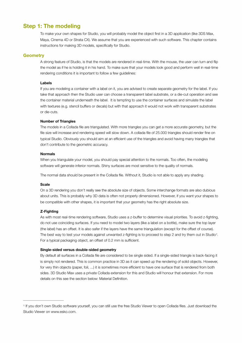
How does Studio apply artwork? But back to the printable parts: To map the artwork correctly on the shape, you have to make sure that the printable part has UV mapping and that the UV mapping is consistent with the physical size that you specified for the printable area:
In the Collada file, the texture coordinates are scaled into a square of 0..1, however, the file also contains a <printable_area> tag (see later) with the proper texture scaling factors: hsizemm by vsizemm.
When you load a Collada file and a PDF file, Studio will take a rectangular portion of the PDF file as specified by the printable area of the Collada file (hsizemm by vsizemm).
In the interface, the user can then choose the position of that clipping rectangle (see left). But he cannot change the size.
This rectangular piece of artwork is print-modeled into a set of textures which are to be addressed with UV-coordinates of 0..1 by 0..1. (with the origin bottom-left).
Workflow When modeling the geometry for the printable area, the texture coordinates (UV mapping) should stay between 0 and 1 and be created in such a way that the PDF artwork will be mapped correctly.
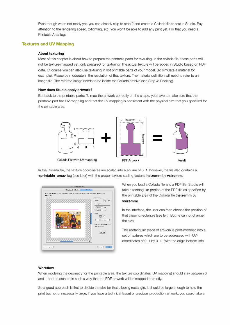
So a good approach is first to decide the size for that clipping rectangle. It should be large enough to hold the print but not unnecessarily large. If you have a technical layout or previous production artwork, you could take a
bounding box of that. If you have artwork, or a technical drawing, you should make an RGB texture image, perfectly cropped at the rectangle you’ve chosen. Use this texture during the modeling process, and remove it at the end.
It is very important to check that your texture coordinates on the printable area do not go outside the 0..1 range. This will cause rendering problems in Studio.
Without the right texture coordinates the artwork will not be placed correctly on the model. It is possible that you see the artwork distorted or you don’t see any artwork at all or that the printable parts shows a single color.
3D modeling software have many tools to make and edit the UV-mapping. This document assumes that you know how to use these tools. 3D CAD software has little to no tools for UV mapping. Below are some more hints that are specific to Studio:
Beware of seams You will need to pay particular attention to this on seams of revolved surfaces. You may need to replicate a column of vertices to avoid range overflow and still get the correct rendered result. Simply creating a cylinder and exporting it to Collada will likely result in texture coordinates outside the 0..1 range, so please be aware of this restriction.
This does not apply to non-printable areas. The texture wrapping modes (clamp, repeat etc) in the Collada file will be honored for non-print-areas, so their texture coordinate range is unrestricted. This is very useful if you have a small repeating texture to use on the non-print-areas for example.
Understand the packaging process To determine the correct texture mapping, you needs to respect the physical size and shape of the object. You also need to understand the manufacturing process (how the print ends up on the shape). For example: An adhesive label on a bottle will require different UV mapping than a shrink sleeve on that same bottle.
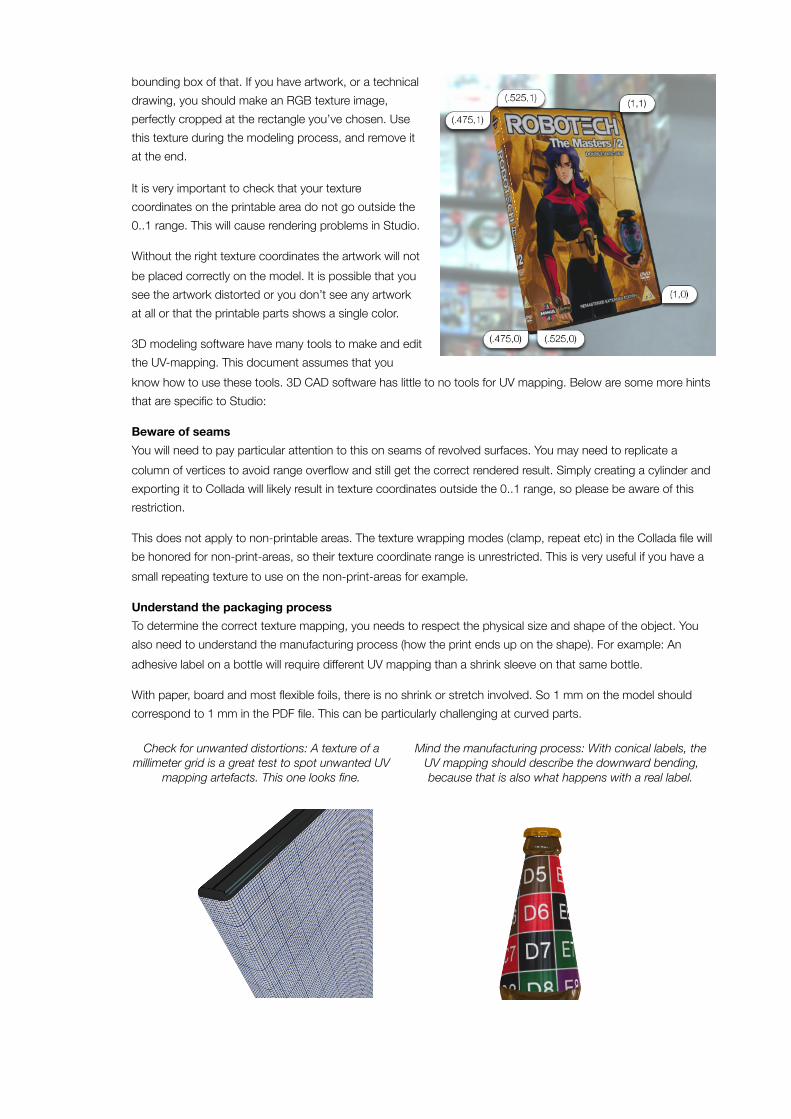
With paper, board and most flexible foils, there is no shrink or stretch involved. So 1 mm on the model should correspond to 1 mm in the PDF file. This can be particularly challenging at curved parts.
Check for unwanted distortions: A texture of a millimeter grid is a great test to spot unwanted UV
mapping artefacts. This one looks fine.
Mind the manufacturing process: With conical labels, the UV mapping should describe the downward bending, because that is also what happens with a real label.
Material Definition
Phong or Blinn Effects Studio only supports materials with phong-style effects. (blinn effects also seem to work reasonably). Your 3D software might use another material or shader model. If you cannot configure your 3D software to use phong materials, you will need to dive into the XML data in the .dae file. All colors are in RGBA where A is always 1. Studio supports the diffuse and specular color and the transparency and shininess values. Materials will look different in Designer quality than in Visualizer quality. This is because Designer only supports opaque materials, white specular colors and only two haze levels. There is a separate whitepaper about tweaking materials in Collada.
Materials and Printable Part To distinguish the printable part from the other parts, the printable part should use a unique material. So in your modeling software, make sure you have one material that you only use for the printable part. Later, when you will add the printable area tag, you will have to identify the printable part based on its material_id
Photo-realism Photorealistic render software can take minutes or hours to calculate a single image. So it is understandable that a real-time rendering engine in Studio does not have the same range of effects at its disposal. Certain effects like refraction, caustics or depth-of-field are currently not possible.
Some effects are possible if you hard-code them in the model: You can calculate a shadow (i.e. with ambient occlusion) and add it to your model as a shadow. It is currently not possible to apply such a shadow to a printable part. That texture will be ignored by the print modeling.
Step 2: Export to Collada When the modeling is complete, you export to a Collada file. It is possible that you need the latest version of your modeling software, or a 3rd party plug-in to be able to save as a Collada file (.dae):
Strata CX: Collada in/export is available in version 5.6 and higher.
3DS Max: You need a plug-in “ColladaMax” (www.feelingsoftware.com).
Maya: You need a plug-in “MayaCollada” (www.feelingsoftware.com).
Luxology Modo: Collada IO comes standard as of Modo 501.
Cinema 4D: Collada import/export is included as of R11
Inspect the Material Definition
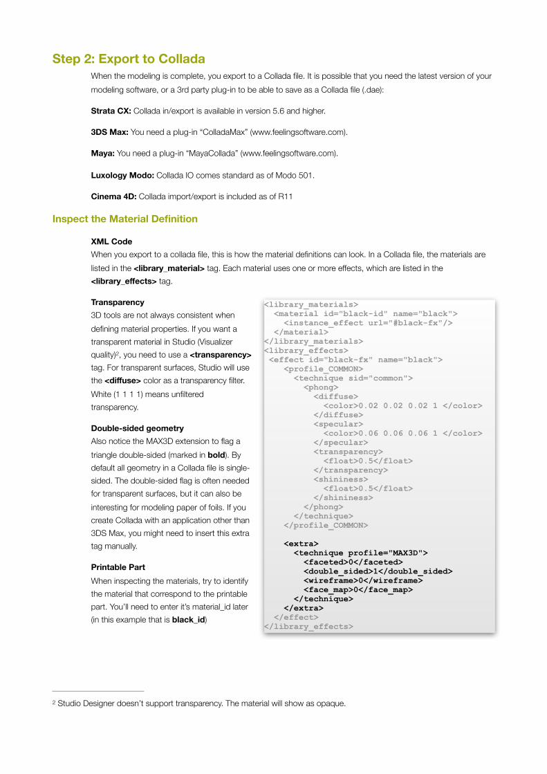
XML Code When you export to a collada file, this is how the material definitions can look. In a Collada file, the materials are listed in the <library_material> tag. Each material uses one or more effects, which are listed in the <library_effects> tag.
Transparency 3D tools are not always consistent when defining material properties. If you want a transparent material in Studio (Visualizer quality) , you need to use a <transparency> 2
tag. For transparent surfaces, Studio will use the <diffuse> color as a transparency filter. White (1 1 1 1) means unfiltered transparency.
Double-sided geometry Also notice the MAX3D extension to flag a triangle double-sided (marked in bold). By default all geometry in a Collada file is single-sided. The double-sided flag is often needed for transparent surfaces, but it can also be interesting for modeling paper of foils. If you create Collada with an application other than 3DS Max, you might need to insert this extra tag manually.
Printable Part When inspecting the materials, try to identify the material that correspond to the printable part. You’ll need to enter it’s material_id later (in this example that is black_id)
Studio Designer doesn’t support transparency. The material will show as opaque.2
<library_materials> <material id="black-id" name="black"> <instance_effect url="#black-fx"/> </material> </library_materials> <library_effects> <effect id="black-fx" name="black"> <profile_COMMON> <technique sid="common"> <phong> <diffuse> <color>0.02 0.02 0.02 1 </color> </diffuse> <specular> <color>0.06 0.06 0.06 1 </color> </specular> <transparency> <float>0.5</float> </transparency> <shininess> <float>0.5</float> </shininess> </phong> </technique> </profile_COMMON>
<extra> <technique profile="MAX3D"> <faceted>0</faceted> <double_sided>1</double_sided> <wireframe>0</wireframe> <face_map>0</face_map> </technique> </extra> </effect> </library_effects>
Step 3: The Printable Part The whole point of making a Collada file for Studio is to apply artwork. Studio can only apply print to a Collada file if that file contains a printable part.
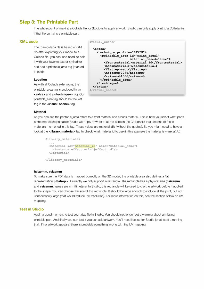
XML code The .dae collada file is based on XML. So after exporting your model to a Collada file, you can (and need) to edit it with your favorite text or xml editor and add a printable_area tag (marked in bold):
Location As with all Collada extensions, the printable_area tag is enclosed in an <extra> and a <technique> tag. Our printable_area tag should be the last tag in the <visual_scene> tag.
Material As you can see the printable_area refers to a front material and a back material. This is how you select what parts of the model are printable: Studio will apply artwork to all the parts in the Collada file that use one of these materials mentioned in this tag. These values are material id’s (without the quotes). So you might need to have a look at the <library_material> tag to check what material id to use (in this example the material is material_id.
<library_materials> ... <material id="material_id" name="material_name"> <instance_effect url="#effect_id"/> </material> ... </library_materials>
hsizemm, vsizemm To make sure the PDF data is mapped correctly on the 3D model, the printable area also defines a flat representation (<flatrep>). Currently we only support a rectangle. The rectangle has a physical size (hsizemm and vsizemm, values are in millimeters). In Studio, this rectangle will be used to clip the artwork before it applied to the shape. You can choose the size of this rectangle. It should be large enough to include all the print, but not unnecessarily large (that would reduce the resolution). For more information on this, see the section below on UV mapping.
Test in Studio Again a good moment to test your .dae file in Studio. You should not longer get a warning about a missing printable part. And finally you can test if you can add artwork. You’ll need license for Studio (or at least a running trial). If no artwork appears, there is probably something wrong with the UV mapping.
<visual_scene> ... <extra> <technique profile="EAVIS"> <printable_area id="print_area1" material_based="true"> <frontmaterial>material_id</frontmaterial> <backmaterial></backmaterial> <flatrep>rect</flatrep> <hsizemm>207</hsizemm> <vsizemm>106</vsizemm> </printable_area> </technique> </extra> </visual_scene>
Recto and Verso As you can see in the XML code, a printable area tag has the notion of a front and back side. Depending on the object that you are modeling, you might want to take a different approach:
Single sided If you don’t care about backside of your printed substrate (because it is only visible from the front), then you set the backmaterial to an un-existing id. You should also not set the double-sided flag on the front material so that back side of the area will then never be rendered.
Double Sided, separate triangles If both sides of the printed substrate are visible and you prefer to model them with two separate sets of triangles (to show material thickness in your model), then you use a different material for the front and back surface. Set the <frontmaterial> and <backmaterial> tags independently to refer to the correct materials on those surfaces. Each surface will need to have its own UV mapping according to the rules below.
Double sided, same triangles If the substrate is really thin (like paper or foil), you might want to use a single set of triangles. Just make sure that you use the Max3D extension for flagging the triangles double sided. Set both <frontmaterial> and <backmaterial> tags to the same material id. The UV mapping should be done for the front side, Studio will take care of the UV mapping on the back side.
Using multiple printable Areas There are also scenes that require multiple printable areas with different graphics (e.g. a corrugated tray with 12 beverage cans would require two printable areas, only two because the 12 cans share one printable part). To model a bottle with two labels, you also require two printable parts3.
You can do this in the Collada file, you make sure each printable part uses a different material and include more than one printable_area tag in the XML code.
You could also consider the two labels as a single printable part: You would layout the UV mapping of both labels on a 3
single rectangular area.

Artwork Template In the printable_area tag, there is subtag flatrep that describes the flat representation. The only flat representation that is supported is a rectangle. So the Studio operator will see a rectangle that needs to be aligned with the artwork. To assist an artwork designer in preparing artwork for this shape more easily, we strongly advice that you also prepare an artwork template in Adobe Illustrator. That way, the Studio user can be sure that his artwork will fit on your shape. You can put the template in a non-printable layer.
Often there will be a template available (a.k.a. the “die”, “key lines”, “CAD file”, “technical file”). In that case you should make sure that your UV mapping is compatible with that template so that Studio can combine your shape with the production-ready PDF artwork.
Step 4: Packing
Collada Archive There are two types of Collada files. The ‘regular’ Collada files have the extension .dae. They are based on XML, so you can inspect and edit them in your favorite text or XML editor. Then there are also Collada Archives. They have the the extension .zae. A Collada archive is nothing more than a ZIP archive with a regular Collada file inside (and some more files). You can use your favorite ZIP utility to unpack a .zae file, or pack files into a .zae. Here’s how the exact content of a .zae archive is supposed to be:
At least one collada file When unzipped, a Collada archive contains at least one Collada file (.dae). If a Collada file refers to other Collada files, then these should also be in the same archive.
A Manifest File The manifest file is called manifest.xml. It is a very small XML file just to point out which of the included Collada files is the main one. It should always be there, even if there is only one Collada file.
<?xml version="1.0"?> <dae_root>can330ml.dae</dae_root>
The manifest file has to be at the top level of the ZIP archive, not in a folder.
Image Files A Collada file also contains material definitions. When a material requires a texture, it will refer to one or more separate image files. Those image files should also be in the archive. Studio supports the following file formats:
• JPEG with RGB data
• PNG with RGB data
Benefits of Collada Archives Although Studio can load both .dae and .zae, we encourage you to use Collada archives for two reasons:
• All-in-one: A regular Collada file may refer to other files and require those files to be present (such as image files for the textures or other Collada files for parts). A Collada archive contains all its data within a single file. This makes it easier and fool-proof to manage and share 3D assets.
• File-size: Because of the ZIP-compression, a Collada archive file is typically four times smaller than the equivalent Collada file.
Making a Collada Archive If you have a regular Collada file (and possibly some textures) you can make a Collada archive yourself:
1. First you collect the collada file(s) and the required texture image files into a folder.
2. Then you make a manifest file (see above), you can do this in a simple text or XML editor. You put the manifest file in the same folder.
3. Then you pack the content of the folder in a zip file. You have to add the files directly to the zip, and not pack the containing folder. That would introduce an extra folder level in the zip file.
4. You change the extension from .zip to .zae.

Step 5: Template If all went well, you now have a Collada archive that you can place in Illustrator so that you can easily switch artwork. To make sure the artwork is laid-out properly, you should also make an artwork template. If the artwork is not laid out correctly, some art elements might not appear on the right place on the 3D object.