prepared by marcia c. belcher, pe - university of...
TRANSCRIPT

Prepared by Marcia C. Belcher, PE
ASCE 7-05: Minimum Design Loads for
Buildings and Other Structures
ASCE 7-05 sets the basic principles of structural engineering that guide the selection of loads.
The Standard defines procedures for determining the load types and the probable combinations of those loads that should be considered in design.
All structures are designed to be safe and serviceable.
Safety and Serviceability are determined by the application of "Limit States".
A limit state is a mathematical statement that shows that a structure has sufficient capacity to resist a particular form of failure that is either safety or service related.
ASCE 7-05: Minimum Design Loads for Buildings and
Other Structures
Safety Limit State: Structure is strong enough to support all load events without causing harm to people and property.
Actual Force < Capacity
Serviceability Limit State: Any limit on the functionality of the structure that is not strength related.
◦ Ie. Deflection and vibration.◦ Neither are safety related, however excessive amounts of
either may cause the structure be useless for its intended purpose.
Actual Behavior < Limit on Behavior
Buildings are classified based on their occupancy.
Classification categories range from I to IV.
Classification reflects a progression of the seriousness of the consequence of failure from lowest hazard to human life (Category I) to the highest (Category IV) .
Table 1.1 from ASCE publication 7-05.
How design loads are calculated will depend on the occupancy category.
Things that will impact classification:
◦ Number of occupants and the period of exposure to extreme events
◦ A structure's status in relation to the community and its safety.
◦ The need for operation of a facility during and after an emergency
◦ The impact of release of hazardous materials as the result of structural failure

Many structural elements receive load from a floor or decking system.
The loads on the elements will be caused by an “effective area” and the “unit load”
ASCE 7-05 prescribes the “unit load” in pounds per square foot of surface.
Tributary Area
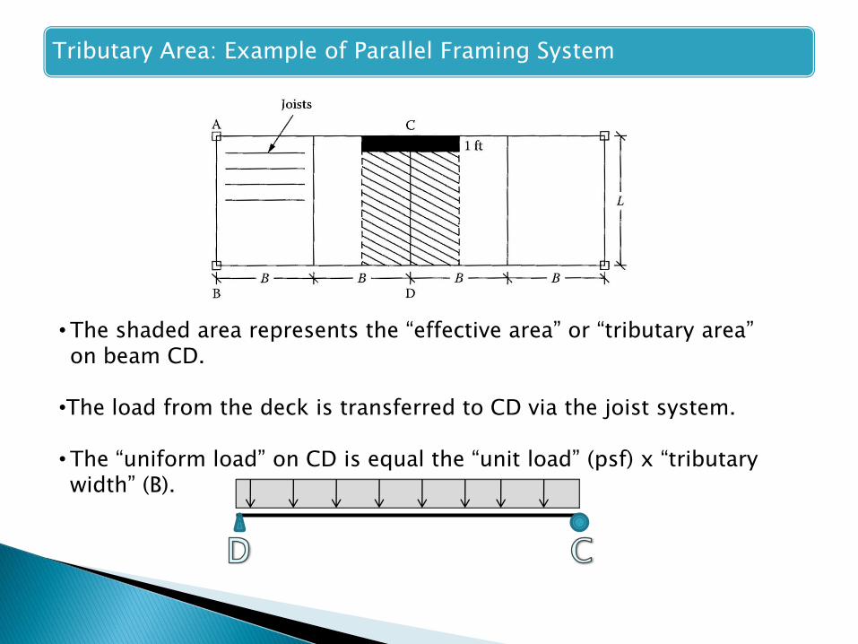
Tributary Area: Example of Parallel Framing System
• The shaded area represents the “effective area” or “tributary area” on beam CD.
•The load from the deck is transferred to CD via the joist system.
• The “uniform load” on CD is equal the “unit load” (psf) x “tributary width” (B).


A large open exhibit building with long
span truss girders.
Long Span Roof Truss Girders Mezzanine Area Awning Roof
Awning Roof with
Hip Beam
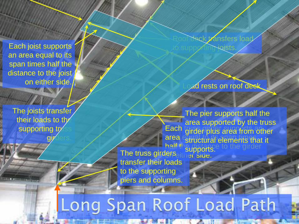
Load rests on roof deck
Roof deck transfers load
to supporting joists.Each joist supports
an area equal to its
span times half the
distance to the joist
on either side.
The joists transfer
their loads to the
supporting truss
girders.
Each truss girder supports an
area equal to its span times
half the distance to the girder
on either side.The truss girders
transfer their loads
to the supporting
piers and columns.
The pier supports half the
area supported by the truss
girder plus area from other
structural elements that it
supports.
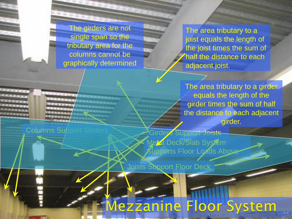
Metal Deck/Slab System
Supports Floor Loads Above
Joists Support Floor Deck
Girders Support JoistsColumns Support Girders
The area tributary to a
joist equals the length of
the joist times the sum of
half the distance to each
adjacent joist.
The area tributary to a girder
equals the length of the
girder times the sum of half
the distance to each adjacent
girder.
The girders are not
single span so the
tributary area for the
columns cannot be
graphically determined

Deck carries load to edge
joist and wall.
Exterior joist carried load to
the supporting cantilever
beam ends
The load diagram for the
cantilever (excluding self wt)
consists of a single point
load at the end of the
cantilever.
The point load consists of
the reaction from the two
supported joists which
equals the tributary area (1/2
the cantilever span times the
spacing of the cantilevers)
times the pressure load on
the floor plus the self weight
of the joist.
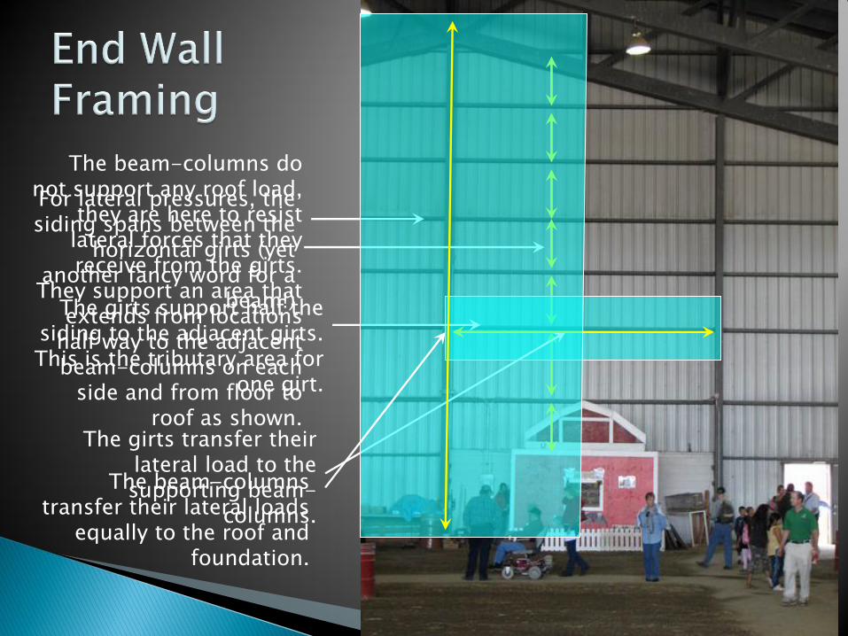
For lateral pressures, the siding spans between the
horizontal girts (yet another fancy word for a
beam!)The girts support half the siding to the adjacent girts. This is the tributary area for
one girt.
The girts transfer their lateral load to the supporting beam-
columns.
The beam-columns do not support any roof load,
they are here to resist lateral forces that they receive from the girts.
They support an area that extends from locations
half way to the adjacent beam-columns on each
side and from floor to roof as shown.
The beam-columns transfer their lateral loads
equally to the roof and foundation.

Example: Tributary Area Load Calculations
For the framing plan shown, ALL of the floor load is being taken by the floor joist. Draw the FBD for beams GH, FE, AB and AD. The design load is 60 psf, L=30 ft and B=10ft.