preparations for the double double bend achromat...
TRANSCRIPT
PREPARATIONS FOR THE DOUBLE-DOUBLE BEND ACHROMAT INSTALLATION IN DIAMOND LIGHT SOURCE
R. P. Walker†, C. Abraham, C.P. Bailey, R. Bartolini1, P. Coll, M.P. Cox, N.P. Hammond, M.T. Heron, S.E. Hughes, J. Kay, I. Martin, S. Mhaskar, A. Miller, A.J. Reed, G. Rehm, E. Rial,
A. Rose, A. Shahveh, H. Shiers, A. Thomson, Diamond Light Source, Oxfordshire, UK 1also at John Adams Institute, Oxford, UK
Abstract We present the status of preparations for a major instal-
lation in the Diamond storage ring which is due to take place in 2016, namely the conversion of one cell of the ring from a double bend achromat (DBA) structure, to a double-DBA, or DDBA.
INTRODUCTION The concept of converting one cell of the Diamond
storage ring from a double bend achromat (DBA) struc-ture to a double-DBA or “DDBA” structure has been described previously [1]. Further details of the accelerator physics optimisation of the modified lattice and the engi-neering solutions that have been adopted are given in [2] and [3] respectively. The motivation for the DDBA pro-ject is to create a new straight section where an in-vacuum insertion device can be located (see Fig.1), since all other straights in the ring are occupied.
Insertion Device
existing DBA cell
modified DDBA cell
BM beamline
ID beamline
Figure 1: Schematic diagram of the existing DBA cell and the modified DDBA cell.
TECHNICAL PROGRESS
Magnets The DDBA cell requires 4 new gradient dipole magnets
(0.8T, 14.4 T/m), of two different lengths, 10 new quad-rupoles (70 T/m) and 10 new sextupoles (2000 T/m2), and 2 new corrector magnets. The design of these magnets was described in [4]. Manufacture of the magnets is near-ing completion at Danfysik A/S, Denmark.
The dipole and quadrupole magnets have been con-structed from solid magnet steel while the sextupoles (and correctors) are laminated to permit the dipole correction fields, which are produced by additional windings, to form part of the fast orbit feedback system. To achieve high field quality in the narrow bore (15 mm radius) quadrupoles and sextupoles, the surfaces of all four (or six) poles for each magnet were wire eroded at the same time in a complete magnet block.
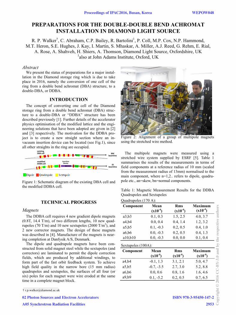
Figure 2: Alignment of a group of multipole magnets using the stretched wire method.
The multipole magnets were measured using a
stretched wire system supplied by ESRF [5]. Table 1 summarises the results of the measurements in terms of field components at a reference radius of 10 mm (scaled from the measurement radius of 13mm) normalised to the main component, where n=1,2.. refers to dipole, quadru-pole etc., an=skew, bn=normal components.
Table 1: Magnetic Measurement Results for the DDBA Quadrupoles and Sextupoles
Quadrupoles (170 A): Component Mean
(x10-4) Rms (x10-4)
Maximum (x10-4)
a3,b3 0.1, 0.3 1.5, 2.5 4.0, 3.7 a4,b4 0.0, 0.4 0.4, 1.4 1.2, 3.2 a5,b5 0.1, -0.3 0.2, 0.5 0.4, 1.0 a6,b6 a10,b10
0.0, -0.3 0.0, -0.3
0.2, 0.5 0.0, 0.0
0.4, 1.3 0.1, 0.4
Sextupoles (100A): Component Mean
(x10-4) Rms
(x10-4) Maximum
(x10-4) a4,b4 -0.1, 1.3 3.1, 2.1 5.0, 4.7 a5,b5 -0.7, -3.5 2.7, 3.0 5.2, 8.8 a6,b6 0.0, 0.6 0.8, 1.6 1.6, 4.6 a9,b9 0.1, -5.2 0.2, 0.5 0.7, 6.5
___________________________________________
Proceedings of IPAC2016, Busan, Korea WEPOW048
02 Photon Sources and Electron Accelerators
A05 Synchrotron Radiation Facilities
ISBN 978-3-95450-147-2
2953 Cop
yrig
ht©
2016
CC
-BY-
3.0
and
byth
ere
spec
tive
auth
ors

The quadrupole quality is very good and close to the tight specification [4]. The sextupoles have small system-atic normal 10-pole and 18-pole components, and some-what larger rms values, nevertheless beam dynamics simulations show that all of the magnets are acceptable.
The dipole magnets were measured using a Hall plate bench, taking data on a rectangular grid. The data were analysed by firstly finding the central trajectory by parti-cle tracking, then interpolating the field at fixed distances perpendicular to the trajectory. The measurement results were in good agreement with simulations. The maximum integrated dipole field error within +/- 10 mm is about 10-4, while the maximum integrated quadrupole field error is about 10-3.
The multipole magnets have all been delivered to DLS and are currently undergoing magnetic alignment using the stretched wire bench (see Fig. 2).
Vacuum The vacuum vessels are a mixture of copper, immedi-
ately following the dipole magnets in order to handle the high synchrotron radiation heat load, and stainless steel, for the dipole vessels and through some of the sextupole magnets for compatibility with the fast orbit feedback system [3]. In operation, pumping is by means of 7 NEG cartridge pumps per girder pair plus one Ion pump below each dipole crotch vessel.
Figure 3: Trial bake-out of the first complete girder string.
The first complete set of vacuum vessels has been de-
livered from FMB GmbH, Germany, and a second set is in production. The first complete girder vessel string has been assembled at DLS and a trial bake-out to 200°C successfully completed (see Fig. 3). One day after bakeout, a pressure of 2x10⁻⁹mbar was achieved when pumped by a single 300 l s-1 turbo-molecular pump and this was still decreasing.
Girders The DDBA magnets, vessels and other components will
be mounted on two 6.75m long steel girders, similar in design to those already employed in Diamond, with the same motorised mover system. The girders, supplied by
Pro-Mil Engineering Ltd., UK, were machined to a flat-ness of 10 m per metre with an overall flatness of 26 µm with dowel holes for locating magnets and vessels posi-tioned to within a tolerance of 20 m.
The water manifolds have been fitted on one of the girders, visible in Fig. 2, to permit the magnets to be powered. The final stage of assembly will be to install the electrical cable trays, which have been incorporated in the design in order to minimise the time required during the DDBA installation shutdown. Figure 4 shows the com-plete 3D model for the girder including the cable trays and electrical junction box which will form one complete pre-assembled unit.
Figure 4: 3D model of one of the DDBA girders.
Power Supplies A design choice was to make use of existing power
supplies and existing power supply designs. Each of the four dipoles has two coils - one powered in series with the existing supply (at 1353 A) and a 200A trim winding, each requiring an additional power supply. The ten quad-rupoles are powered by existing power supplies. The first seven sextupoles reuse the existing power supply modi-fied to ensure optimum performance with the new mag-nets. For the remaining three sextupoles, new power sup-plies were built.
Fabrication of the additional 100 A and 200A supplies, as well as 5A corrector power supplies, has been complet-ed. Testing has been completed and has demonstrated stability to within 10ppm and current ripple to less than 3ppm. Control loop optimisation of the corrector power supplies has been completed to ensure a minimum of 600Hz bandwidth which is required for the fast orbit feedback system.
Control System and High Level Software For the interface layer of the control system, the chang-
es for the DDBA cell largely involve additional devices and parameters and could be accommodated within the existing EPICS IOCs and the existing instrumentation racks. For the machine protection system, the opportunity was taken to use remote IO as part of the PLC protection systems for non-interlocking temperatures. While all
WEPOW048 Proceedings of IPAC2016, Busan, Korea
ISBN 978-3-95450-147-2
2954Cop
yrig
ht©
2016
CC
-BY-
3.0
and
byth
ere
spec
tive
auth
ors
02 Photon Sources and Electron Accelerators
A05 Synchrotron Radiation Facilities

interlocks were still hardwired to the instrumentation area, due to uncertainty in the long term reliability of the remote IO hardware in the radiation environment of the tunnel.
With limited commissioning time available a number of system changes were made during 2015 and 2016 to min-imise shutdown work. These included a new Frontend control system to use a higher density solution thereby freeing rack space and adding the additional electron BPM processing electronics and changes to the Fast Orbit Feedback to cope with the increase in the number of cor-rectors.
Matlab Middle Layer has been updated and tested against both a virtual accelerator and soft record versions of all PSU IOCs for both standard and low-alpha optics. LOCO has been updated for both modes and optimal parameter ranges identified in each case. Both slow (SOFB) and fast orbit feedback (FOFB) have been stud-ied: SOFB will use 8 correctors and 8 BPMs, while FOFB (which never runs concurrently with SOFB) will use 6 correctors and 6 BPMs. The adaptation of tune-feedback has also been studied to determine the appropriate quad-rupoles to use in the feedback. Vertical emittance and RF feedbacks remain to be studied. The aim is to be well prepared for what will be an aggressive recommissioning of the machine after the DDBA installation.
Cabling Minimising the shutdown period needed for DDBA in-
stallation has required an extensive amount of cabling work, which began in March 2014. A complete set of temporary cables for the existing cell of the storage ring was first installed via an alternative route through the personnel labyrinth. Cell components were then progres-sively connected onto the temporary cables and the exist-ing cables which are not going to be re-used were re-moved. The next stage was then to install new cables, and terminate them at a dummy junction box, the same as the one that will be installed on the girder shown in Fig. 4. In this way, when the girders are finally installed, they can be quickly connected up without any cable cutting or terminating and with greater confidence of correctness. The temporary cables will initially remain in position, in case a reversion to the old configuration is needed.
STATUS AND PLANS Following the trial bakeout of the vessel string on the
first girder, the vessels were removed and the multipole magnets were installed and aligned using the stretched wire equipment. The magnet tops have been removed and the vessels are in the process of being assembled (Fig. 5). The next steps will be to perform a bakeout, re-install the magnet tops, install the dipole magnets sideways around the vessel, then complete the electrical wiring. The same procedure will be repeated for the second girder.
Figure 5: Installation of the vacuum vessel string on the first girder.
Following some technical difficulties during the pro-
duction of magnets and vacuum vessels, the decision has been taken to delay the installation shutdown by two months, which is now due to take place between Oct. 7th and Dec. 5th 2016.
A detailed installation plan has been drawn up, broken down into 5 stages: DBA removal and preparation for DDBA installation (~3 weeks), DDBA installation (~1 week), systems commissioning and hand-over (~3½ weeks), start-up and beam commissioning (2 weeks). The beam commissioning plan is also well advanced, starting from on-axis injection and first turn threading through to re-establishing reliable user operation in standard 900-bunch modes. Other beam modes will be made available progressively run-by-run: hybrid multibunch + single bunch, 135-bunch mode and finally low-alpha mode, optimisation of which has proved to be particularly chal-lenging [6].
REFERENCES [1] R.P. Walker et al., in Proc. IPAC’14, Dresden, Germany,
pp. 331-333.
[2] R. Bartolini et al., in Proc. IPAC’14, pp. 322-324.
[3] J. Kay et al., in Proc. IPAC’14, pp. 328-330.
[4] C.P. Bailey et al., in Proc. IPAC’14, pp. 1319-1321.
[5] G. Le Bec et al., “Stretched wire measurements of multipole accelerator magnets”, Phys. Rev. ST Accel. Beams, vol. 15, p. 022401, 2012.
[6] I.P.S. Martin et al., in Proc. IPAC’15, Richmond, VA, USA, pp. 525-527.
Proceedings of IPAC2016, Busan, Korea WEPOW048
02 Photon Sources and Electron Accelerators
A05 Synchrotron Radiation Facilities
ISBN 978-3-95450-147-2
2955 Cop
yrig
ht©
2016
CC
-BY-
3.0
and
byth
ere
spec
tive
auth
ors