preparation of novel carbon microfiber/carbon nanofiber-dispersed polyvinyl alcohol-based...
TRANSCRIPT

Materials Science and Engineering C 33 (2013) 1702–1709
Contents lists available at SciVerse ScienceDirect
Materials Science and Engineering C
j ourna l homepage: www.e lsev ie r .com/ locate /msec
Preparation of novel carbon microfiber/carbon nanofiber-dispersed polyvinylalcohol-based nanocomposite material for lithium-ion electrolyte battery separator
Ajit K. Sharma a, Prateek Khare a, Jayant K. Singh a,⁎, Nishith Verma a,b,⁎⁎a Department of Chemical Engineering, Indian Institute of Technology Kanpur, Kanpur 208016, Indiab Center for Environmental Science and Engineering, Indian Institute of Technology Kanpur, Kanpur 208016, India
⁎ Corresponding author. Tel.: +91 512 2596124; fax:⁎⁎ Correspondence to: N. Verma, Department of Chemtute of Technology Kanpur, Kanpur 208016, India. Tel.:512 2590104.
E-mail addresses: [email protected] (J.K. Singh), nis
0928-4931/$ – see front matter © 2012 Elsevier B.V. Allhttp://dx.doi.org/10.1016/j.msec.2012.12.083
a b s t r a c t
a r t i c l e i n f oArticle history:Received 4 March 2012Received in revised form 3 November 2012Accepted 26 December 2012Available online 31 December 2012
Keywords:Li-ion battery separatorPolyvinyl alcoholCarbon micro-nanofibersSuspension polymerizationIonic conductivity
Anovel nanocomposite polyvinyl alcohol precursor-basedmaterial dispersedwith theweb of carbonmicrofibersand carbon nanofibers is developed as lithium (Li)-ion electrolyte battery separator. The primary synthesissteps of the separator material consist of esterification of polyvinyl acetate to produce polyvinyl alcohol gel,ball-milling of the surfactant dispersed carbon micro-nanofibers, mixing of the milled micron size (~500 nm)fibers to the reactant mixture at the incipience of the polyvinyl alcohol gel formation, and the mixing of hydro-phobic reagents along with polyethylene glycol as a plasticizer, to produce a thin film of ~25 μm. The producedfilm, uniformly dispersed with carbon micro-nanofibers, has dramatically improved performance as a batteryseparator, with the ion conductivity of the electrolytes (LiPF6) saturatedfilmmeasured as 0.119 S-cm−1, approx-imately two orders of magnitude higher than that of polyvinyl alcohol. The other primary characteristics ofthe produced film, such as tensile strength, contact angle, and thermal stability, are also found to be superior tothe materials made of other precursors, including polypropylene and polyethylene, discussed in the literature.Themethod of producing thefilms in this study is novel, simple, environmentally benign, and economically viable.
© 2012 Elsevier B.V. All rights reserved.
1. Introduction
Lithium-ion battery has an anode and a cathode separated by a thinmicroporous film made of a polymeric or an inorganic material, alsoknown as separator. The role of the separator is to keep the positiveand negative electrodes separated. It prevents internal short-circuitingand simultaneously permits the transport of the ionic charge carriers.It must be chemically and electrochemically stable toward the electro-lytes, in particular during the battery operation. As the electrodes andseparator are wound together during the battery assembling, the sepa-rator must be mechanically strong to withstand the induced high ten-sion; otherwise, there is a risk of short-circuiting in the battery duringthe operation. In addition, the separator material should be thin andshould have relatively small electrical resistivity or large ion conductiv-ity, good electrolyte wettability, and thermal stability [1,2]. The last butnot the least, the material should be inexpensive. In general, it is ex-tremely difficult and challenging to develop such materials.
Polyethylene (PE) and polypropylene (PP) are two common precur-sors used for preparing separators for Li-ion batteries. The PE and PPseparators have good tensile strength and are electrochemically sta-ble toward the electrolyte and electrode materials, preventing internal
+91 512 2590104.ical Engineering, Indian Insti-+91 512 2596124; fax: +91
[email protected] (N. Verma).
rights reserved.
short-circuiting or rapid overcharging of the battery. One of the majordrawbacks of such separators is relatively poor compatibility with liq-uid electrolytes because of their hydrophobic property. Another majordrawback is the high manufacturing cost of PE and PP [3,4].
Many studies have been performed for modifying the PE and PPseparator materials using various methods, such as coating them withgel electrolytes [5] and polymeric nanoparticles [6]; SiO2 deposition[7]; and grafting with acrylic acid and diethyleneglycol–dimethacrylate[8], methyl methacrylate [9] and polyacrylate [10], and with siloxaneusing electron beam irradiation [11]. A PP-PE composite modifiedby the electrospun polyacrylonitrile (PAN) nanofibers also has beenprepared [12]. Suchmodified separators exhibit relatively superior me-chanical strength and compatibilitywith the liquid electrolyte, althoughthe manufacturing cost of the modified PE- and PP-based separatorsis high.
The studies on the development of Li-ion battery separators madeof non-PP- and non-PE-based precursors are few. Kuribayashi [13] de-veloped a cellulose precursor-based composite material by incorporat-ing fine fibrillia cellulosic fibers in a microporous cellulosic film. ThePVdF–HFP precursor-based separators with or without reinforcementwith suitable inorganicfillers have also been prepared [14,15]. However,such materials are relatively expensive.
Polyvinyl alcohol (PVA) is a relatively low-cost and environmen-tally benign material. PVA has been used as an electrolyte in Li-ionbattery [16]. It also has been used as a separator, in alkaline batteryapplications [17,18] and also for zinc electrode-based cells [19]. Toour knowledge, PVA has not been used as a precursor for the battery
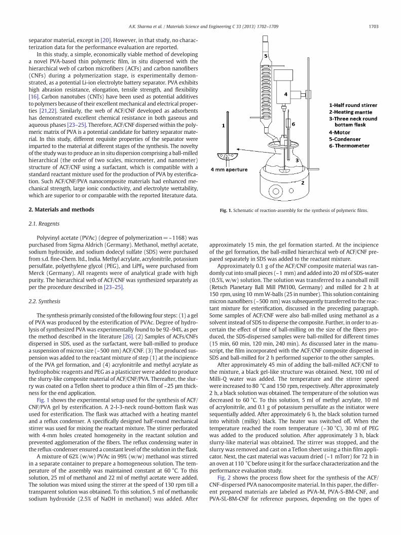
Fig. 1. Schematic of reaction-assembly for the synthesis of polymeric films.
1703A.K. Sharma et al. / Materials Science and Engineering C 33 (2013) 1702–1709
separator material, except in [20]. However, in that study, no charac-terization data for the performance evaluation are reported.
In this study, a simple, economically viable method of developinga novel PVA-based thin polymeric film, in situ dispersed with thehierarchical web of carbon microfibers (ACFs) and carbon nanofibers(CNFs) during a polymerization stage, is experimentally demon-strated, as a potential Li-ion electrolyte battery separator. PVA exhibitshigh abrasion resistance, elongation, tensile strength, and flexibility[16]. Carbon nanotubes (CNTs) have been used as potential additivesto polymers because of their excellentmechanical and electrical proper-ties [21,22]. Similarly, the web of ACF/CNF developed as adsorbentshas demonstrated excellent chemical resistance in both gaseous andaqueous phases [23–25]. Therefore, ACF/CNF dispersedwithin the poly-meric matrix of PVA is a potential candidate for battery separator mate-rial. In this study, different requisite properties of the separator wereimparted to the material at different stages of the synthesis. The noveltyof the studywas to produce an in situ dispersion comprising a ball-milledhierarchical (the order of two scales, micrometer, and nanometer)structure of ACF/CNF using a surfactant, which is compatible with astandard reactant mixture used for the production of PVA by esterifica-tion. Such ACF/CNF/PVA nanocomposite materials had enhanced me-chanical strength, large ionic conductivity, and electrolyte wettability,which are superior to or comparable with the reported literature data.
2. Materials and methods
2.1. Reagents
Polyvinyl acetate (PVAc) (degree of polymerization=~1168) waspurchased from Sigma Aldrich (Germany). Methanol, methyl acetate,sodium hydroxide, and sodium dodecyl sulfate (SDS) were purchasedfrom s.d. fine-Chem. ltd., India. Methyl acrylate, acrylonitrile, potassiumpersulfate, polyethylene glycol (PEG), and LiPF6 were purchased fromMerck (Germany). All reagents were of analytical grade with highpurity. The hierarchical web of ACF/CNF was synthesized separately asper the procedure described in [23–25].
2.2. Synthesis
The synthesis primarily consisted of the following four steps: (1) a gelof PVA was produced by the esterification of PVAc. Degree of hydro-lysis of synthesized PVAwas experimentally found to be 92–94%, as perthe method described in the literature [26]. (2) Samples of ACFs/CNFsdispersed in SDS, used as the surfactant, were ball-milled to producea suspension of micron size (~500 nm) ACF/CNF. (3) The produced sus-pension was added to the reactant mixture of step (1) at the incipienceof the PVA gel formation, and (4) acrylonitrile and methyl acrylate ashydrophobic reagents and PEG as a plasticizer were added to producethe slurry-like composite material of ACF/CNF/PVA. Thereafter, the slur-ry was coated on a Teflon sheet to produce a thin film of ~25 μm thick-ness for the end application.
Fig. 1 shows the experimental setup used for the synthesis of ACF/CNF/PVA gel by esterification. A 2-l-3-neck round-bottom flask wasused for esterification. The flask was attached with a heating manteland a reflux condenser. A specifically designed half-round mechanicalstirrer was used for mixing the reactant mixture. The stirrer perforatedwith 4-mm holes created homogeneity in the reactant solution andprevented agglomeration of the fibers. The reflux condensing water inthe reflux-condenser ensured a constant level of the solution in theflask.
A mixture of 62% (w/w) PVAc in 99% (w/w) methanol was stirredin a separate container to prepare a homogeneous solution. The tem-perature of the assembly was maintained constant at 60 °C. To thissolution, 25 ml of methanol and 22 ml of methyl acetate were added.The solution was mixed using the stirrer at the speed of 130 rpm till atransparent solution was obtained. To this solution, 5 ml of methanolicsodium hydroxide (2.5% of NaOH in methanol) was added. After
approximately 15 min, the gel formation started. At the incipienceof the gel formation, the ball-milled hierarchical web of ACF/CNF pre-pared separately in SDS was added to the reactant mixture.
Approximately 0.1 g of the ACF/CNF composite material was ran-domly cut into small pieces (~1 mm) and added into 20 ml of SDS-water(0.5%, w/w) solution. The solution was transferred to a nanoball mill(Retsch Planetary Ball Mill PM100, Germany) and milled for 2 h at150 rpm,using10 mmW-balls (25 in number). This solution containingmicron nanofibers (~500 nm)was subsequently transferred to the reac-tant mixture for esterification, discussed in the preceding paragraph.Some samples of ACF/CNF were also ball-milled using methanol as asolvent instead of SDS to disperse the composite. Further, in order to as-certain the effect of time of ball-milling on the size of the fibers pro-duced, the SDS-dispersed samples were ball-milled for different times(15 min, 60 min, 120 min, 240 min). As discussed later in the manu-script, the film incorporated with the ACF/CNF composite dispersed inSDS and ball-milled for 2 h performed superior to the other samples.
After approximately 45 min of adding the ball-milled ACF/CNF tothe mixture, a black gel-like structure was obtained. Next, 100 ml ofMilli-Q water was added. The temperature and the stirrer speedwere increased to 80 °C and 150 rpm, respectively. After approximately2 h, a black solutionwas obtained. The temperature of the solution wasdecreased to 60 °C. To this solution, 5 ml of methyl acrylate, 10 mlof acrylonitrile, and 0.1 g of potassium persulfate as the initiator weresequentially added. After approximately 6 h, the black solution turnedinto whitish (milky) black. The heater was switched off. When thetemperature reached the room temperature (~30 °C), 30 ml of PEGwas added to the produced solution. After approximately 3 h, blackslurry-like material was obtained. The stirrer was stopped, and theslurry was removed and cast on a Teflon sheet using a thin film appli-cator. Next, the cast material was vacuum dried (~1 mTorr) for 72 h inan oven at 110 °C before using it for the surface characterization and theperformance evaluation study.
Fig. 2 shows the process flow sheet for the synthesis of the ACF/CNF-dispersed PVA nanocomposite material. In this paper, the differ-ent prepared materials are labeled as PVA-M, PVA-S-BM-CNF, andPVA-SL-BM-CNF for reference purposes, depending on the types of

1704 A.K. Sharma et al. / Materials Science and Engineering C 33 (2013) 1702–1709
reagents used and the methods. PVA-M represents the PVA-basedseparator film prepared by incorporating hydrophobic monomers(acrylonitrile and methyl acrylate) without ACF/CNF. PVA-S-BM-CNFrepresents the film prepared by dispersing ball-milled ACF/CNF inSDS, whereas PVA-SL-BM-CNF represents the film prepared by dispers-ing ball-milled ACF/CNF in methanol. All materials were prepared intriplicates for the reproducibility of their properties discussed in thenext sections.
2.3. Performance evaluation
The ACF/CNF/PVA composite film prepared as a battery separatorwas characterized for the electrolyte-ion conductivity, contact angle,tensile strength, surface functional groups, thermal stability, air perme-ability and mean pore size. The surface morphology of the sampleswas studied using the Supra 40 VP Field Emission scanning electronmicroscopy (SEM) procured from Zeiss, Germany. All images were
Esterification by NaOH
(2.45% w/w in methanol)
su
Addition of water in the
reaction mixture at 60oC
Sequential additions of
monomers and initiators
APlast
Nanocomposite film
Homogeneous solution of PVAc
(62% w/w)
Gel-formation starts
D1
vac
Fig. 2. Process flow sheet for se
capturedwith VPSE detector at the accelerating voltage of 20 kV and fil-ament current of 2.37 A at a working distance of 6–7 mm. The resistivityor ionic conductivity was measured by an I-V source meter (Keithley6221, USA). The tensile strength was measured by a tensile machine(UTM-Zwick/roell-Z010, Germany). The electrolyte wettability wasascertained by measuring the contact angle using the goniometer(Rame-hart-200, Germany). Infrared (IR) spectrum of the sampleswas obtained using FTIR spectrophotometer (Tensor 27, Brucker,Germany). The spectra were taken on the attenuated total reflectance(ATR) mode using Ge crystal, over wave numbers ranging between400 and 4000 cm−1. Differential scanning calorimetry (DSC) analysis(Toledo-Mettler, USA) was carried out to ascertain the thermal stabilityover the temperature range between 30 °C and 350 °C. The film thick-ness was measured by an optics-based thin-film measurement system(Filmetrix, US). Air permeability and the mean pore size were deter-mined using the automated gas permeability measurement instru-ment (model no. CCF-20-A, PMI, Porous Materials, Inc., USA).
Ball milling of ACF/CNF in rfactant (SDS)
dd icizer Gel structure
Casting on Teflon sheet
rying at 00oC in uum oven
ACF/CNF
parator material synthesis.

1705A.K. Sharma et al. / Materials Science and Engineering C 33 (2013) 1702–1709
3. Results and discussion
3.1. Surface morphology
The surface morphology of the prepared material was investigatedusing the SEM images. Fig. 3 shows the images of PVA-M andPVA-S-BM-CNF films. The images are shown at low (100 and 500X)and high (10KX) magnifications for both materials. As observedfrom Fig. 3A for PVA-M and Fig. 3B for PVA-S-BM-CNF, both materialsare porous. However, the external surface of PVA-S-BM-CNF is ob-served to be rough when compared with the PVA-M film. As also ob-served from the images shown in Fig. 3A-2 and B-2, the number ofpores or pores-content has considerably increased in PVA-S-BM-CNFwhen compared with its counterpart PVA-M. As shown later, the en-hanced pores content is favorable for the absorbability of the electro-lytes and high ionic conductivity. Fig. 3A-3 and B-3 shows thecorresponding images at higher magnifications. There are two
Fig. 3. SEM analysis of PVA-M (A) and PVA-S-BM-CNF (B) membrane at low (100
salient observations: (1) The average size of most of the pores inPVA-S-BM-CNF is below 1 μm. (2) The ACF/CNF particles with sub-micron length and nanometer diameter are dispersed within the film.The important feature of the film is that the dispersed fibers wereembedded within the polymeric films along the film surface and nottransversely protruded outside the external surface. As discussed later,dispersion of ACF/CNF within the film was responsible for increasedmechanical strength, wettability, and ion conductivity.
The mean pore size and air permeability were determined usingthe automated gas permeability measurement instrument (ModelNo. CCF-20-A, PMI, Porous Materials, Inc., USA). The mean pore sizeof PVA-M and PVA-S-BM-CNF were measured to be approximately228 nmand 180 nm, respectively. The corresponding Darcy permeabil-ity constant wasmeasured to be 41×10−5 and 27×10−5, respectively.Therefore, the addition of CNFs in the polymeric matrix results in adecrease in the mean pore size and the permeability constant. Thenumerical value of the mean pore size obtained for the synthesized
X (A-1, B-1) & 500X (A-2, B-2)) and higher (10KX (A-3, B-3)) magnification.

1706 A.K. Sharma et al. / Materials Science and Engineering C 33 (2013) 1702–1709
material in this study is within the order of magnitude of the datareported in the literature for the PVdF and PE precursors-based Li-ionbattery separators [27]. Also, Arora et al. [1] have recommended porediameterb1 μm or 1000 nm for such batteries. Further, Lee et al.[28,29] have experimentally measured the permeability constant of2×10−5 or greater for PE-based battery separators.
As mentioned earlier, some samples (PVA-SL-BM-CNF) were pre-pared without using the surfactant (SDS), in which case ACFs/CNFswere dispersed in methanol, the reagent used as a solvent for esteri-fication. However, for suchmaterials, theporeswere found to be blockedby the fibers, and the external surface was covered with fibers, as ob-served from the SEM images (not presented here). The quality ofsuch materials also was found to be considerably inferior to that ofPVA-S-BM-CNF, having reduced mechanical strength and larger contactangle, as discussed later. From these results,we conclude that the disper-sion of ACF/CNF using a surfactant was critical to producing a superi-or quality of thefilm for battery separators. On the other hand, dispersingfibers in the solvent (methanol) used for esterification resulted inagglomeration.
The time of ball-milling for ACF/CNF in the surfactant was found tobe critical for uniform incorporation of the fibers within the preparedpolymeric film. Relatively longer time (>120 min) of milling producedbreakage of the fibers and destruction of its micro-mesopores. On theother hand, shorter time produced relatively longer (~500 nm) andnonuniform dispersion within the film.
3.2. Ionic conductivity
The ionic conductivity measurements were performed on theprepared materials after saturating them with LiPF6 liquid electrolyte.The liquid electrolyte was prepared by mixing equal volumes (5 cm3)of ethylene carbonate (EC) and dimethyl carbonate (DMC). The cali-brated amount of LiPF6 powder was added to the above liquid to pre-pare 1 M LiPF6 solution [30]. The synthesized separator materials,PVA-M, PVA-S-BM-CNF, and PVA-SL-BM-CNF,were cut into small pieces(10 mm×10 mm) and dipped in the electrolyte at 35 °C for 2 h. The(fabric) samples of ACF/CNF also were cut into the same dimensionsand saturated with the electrolyte. After taking out the wet samples,the excess electrolyte was removed by soaking with tissue papers.Some sampleswere preparedwithout saturating themwith the electro-lytes for the comparison purpose. For the measurement of electricalresistance, contacts of thin Cu-wires were made on the preparedfilm sample by silver soldering. The measurements were made in twoways (types A and B). In type A measurement, the resistance was mea-sured directly across thefilm,with contactsmade on the top and bottomsides of the film. In type B measurement, the contacts were made onthe two sides, separated by a distance (thewidth of thefilm). The surfaceresistance of the film was therefore included in type B measurement.
The ionic conductivity was calculated from the measurement ofthe resistance. The results are presented in Table 1. The data for resis-tance and conductivity are presented for each sample, with andwithout being saturated with the electrolyte. All data are reportedcorresponding to type Ameasurement, unless and until specified other-wise. As shown in the table, the ionic conductivity of PVA-M is thesmallest (1.17×10⁻³ S-cm−1), and that of ACF/CNF is the largest(1.57 S-cm−1). Among all polymeric films, the ionic conductivity ofPVA-S-BM-CNF is the largest (1.19×10⁻¹ S-cm−1). Thus, the advan-tage of in situ incorporating ACF/CNF in PVA using a surfactant is ob-vious. The dispersion of conductive hierarchical carbon web in thepolymeric film has caused a remarkable increase (approximately bytwo orders of magnitude) in the conductivity. The ionic conductivity ofthe different materials (with or without electrolyte) is in the followingorder: ACF/CNF>PVA-S-BM-CNF>PVA-SL-BM-CNF>PVA-M. As alsoobserved from the table, the samples prepared by saturating themwith the electrolytes had smaller specific resistance and larger ionicconductivity than those prepared without the electrolytes.
To our knowledge, the ionic conductivity (1.19×10⁻¹ S-cm−1) ofPVA-S-BM-CNF obtained in this study is significantly larger than thatin the literature data, for example, larger than 6.76×10⁻⁴ S-cm−1
for the PAN-based separator [31], 1.95×10⁻³ S-cm−1 for LLTO/PANcomposite fiber [5], 3.1×10⁻⁵ S-cm−1 for the MMA-modified PEseparator [6], 3.92×10⁻⁴ S-cm−1 for PVdF/HFP-based separator [32],and 8.90×10⁻⁴ S-cm−1 for PVdF/PE-based separator material [30].
Table 1 also presents the data for PVA-S-BM-CNF, correspondingto type B measurements. As shown, type B measured electrical resis-tance is more than 1000 times the corresponding resistance obtainedby type A measurement. The data have significance. The carbon fibersare embedded within the film. Therefore, the electrical resistancemeasured by type B measurement includes the significantly large sur-face resistance of the polymeric film and the small resistance acrossthe film modified by the fibers.
3.3. Contact angle
The contact angle measurements of the PVA-M, PVA-S-BM-CNF,and PVA-SL-BM-CNF films were carried out to ascertain the effectsof the incorporated carbon fibers within the polymeric film on the wet-tability of the electrolyte (LiPF6). The measurements were made forthree different samples for each of the four types of films prepared.The contact angles reported in this paper are within ±2°. Fig. 4 showsthe images (photographs) of contact angles for different materialsprepared in this study, as obtained from the instrument (contact anglegoniometer). As per the usual procedure, a drop of electrolyte wasdeposited on the surface of the material, and the contact angle wasimmediately measured and recorded. As shown in the figure, thecontact angle for PVA-M (Fig. 4A) was measured as 33.3°. The contactangle significantly decreased to 21.1° for PVA-S-BM-CNF (Fig. 4B), indi-cating significant increase in thewettability of the surfacewith the elec-trolyte. On the other hand, the contact angle (26.6°) measured forPVA-SL-BM-CNF (Fig. 4C) was smaller than that for PVA-M but greaterthan that for PVA-S-BM-CNF. The data re-demonstrate the advantageof using a surfactant for incorporating ACF/CNF within the polymericfilm. Interestingly, ACF/CNF was found to be completely wet with theelectrolytes. In fact, the drop of the electrolytes immediately dispersedinto the surface upon deposition during themeasurement. Table 2 sum-marizes the contact anglesmeasured for differentmaterials. The contactangle for ACF/CNF is listed as approximately zero in the table.
From the data presented in the preceding paragraph, we concludethat PVA-S-BM-CNF synthesized in this study by in situ incorporatingthe SDS-dispersed ACF/CNF in the film had the smallest contact angleand the maximum wettability with the electrolyte. Approximately zerocontact angle of LiPF6 (mixed with EC and DMC) observed on ACF/CNFreflects relatively higher adsorption of the electrolyte by the carbonsurface. On the other hand, relatively larger contact angle observed onPVA-M reflects the “phobic” behavior of the surface with the liquidand consequently less adsorption. Further, relatively larger wettabil-ity of the carbon surface by the electrolyte may be attributed to thereduction in the effective interfacial surface tension, resulting in the in-creased adsorption [33].
The use of the surfactant resulted in a uniform dispersion of theball-milled ACF/CNF within the polymeric matrix, which rendered thePVA film “phillic”. Therefore, the contact angle of PVA-S-BM-CNF wasmeasured to be in between that of ACF/CNF and PVA, and greater thanthat of PVA-SL-BM-CNF. The use of solvent (instead of surfactant)caused agglomeration of the CNF fibers in the latter film and therefore,less adsorption of the electrolyte and increase in the interfacial forcesand contact angle.
The smallest contact angle (21.1°) obtained for PVA-S-BM-CNFis comparable with or smaller than those for a few commercial sep-arators: 15.8° for the ionic liquid modified separator, 21.6° for plainseparator, 60.9° for Celgard-2320, and 53.1° for Celgard-2730 [34].For the Li-ion battery, the wettability of the separator by the electrolytes

Table 1Specific resistance and ionic conductivity of prepared materials.
Sample ID Without electrolyte With electrolyte
Resistance (Ω) Specific resistance (Ω-cm) Ionic conductivity (S-cm−1) Resistance (Ω) Specific resistance (Ω-cm) Ionic conductivity (S-cm−1)
Type-A measurementACF/CNF 0.05 1.06 9.4×10⁻¹ 0.03 6.38×10⁻¹ 1.57PVA-M 3.78 1.51×10³ 6.61×10⁻⁴ 2.140 8.56×10² 1.17×10⁻³
PVA-SL-BM-CNF 0.085 3.40×101 2.94×10⁻² 0.038 1.52×101 6.58×10⁻²
PVA-S-BM-CNF 0.079 3.16×101 3.16×10⁻² 0.021 8.40 1.19×10⁻¹
Type-B measurementPVA-S-BM-CNF 343.000 1.37×10⁵ 7.29×10⁻⁶ 206.000 8.24×10⁴ 1.21×10⁻⁵
Type –A Type –B
Soldering at the top surface of film
Soldering at the bottom surface of film
Soldering
Soldering
1707A.K. Sharma et al. / Materials Science and Engineering C 33 (2013) 1702–1709
is critical for the battery performance because the separator withgood wettability can effectively retain the electrolyte solutions andfacilitate the electrolyte ions to diffuse through its pores [1,2].
3.4. Tensile strength as mechanical property
The stress–strain relationship was obtained for evaluating thecomparative tensile strength of the prepared films as separator. Asper the standard method [35], a rectangular (50 mm×5 mm) seg-ment of the prepared samples (thickness=25 μm) was subjected tothe initial strain ramp of 0.5 per min and preload force of 0.001 N.The sample temperature was set at 35 °C. The initial distance be-tween the holder grips was set at 20 mm.
Fig. 5 shows the stress–strain curves of different samples plottedfrom the data. As observed, PVA-S-BM-CNF (the proposed separatormaterial in this study) has the maximum tensile strength when
Fig. 4. Contact angle of (A) PVA-M (33.3°), (B) PVA-S-BM-CNF (21.1°), and (C) PVA-SL-BM-CNF (26.9°) films saturated with electrolyte (LiPF6).
compared with other polymeric materials. The maximum (yield) ten-sile strength of PVA-M was measured to be 789 kg-f-cm−2. On theother hand, that of ACF/CNF was measured to be expectedly large(2830 kg-f-cm−2). It is obvious that the tensile strength significantlyincreased (2146 kg-f-cm−2) for PVA-S-BM-CNF, approximately threetimes larger than that of PVA-M, on incorporating ACF/CNF. Thetensile strength of different polymeric samples was in the followingorder: PVA-S-BM-CNF>PVA-SL-BM-CNF>PVA-M. Also, a sharp increaseobserved for the tensile strength of ACF/CNF during the load test isthe characteristic of carbon fibers, which is different for polymericmaterials. The latter materials are gradually stretched (elongated)till the yield stress on increasing load.
The calculated values for the tensile strength of the prepared filmsare summarized in Table 2. The data emphasize the advantage ofincorporating high tensile ACF/CNF within the polymeric film, andin addition, the use of surfactant for dispersing ACF/CNF. The tensilestrength (2146 kg-f-cm−2) of PVA-S-BM-CNF obtained in this studymay be compared to the same for a few commercial Li-ion batteryseparators: 1900 kg-f-cm−2 for Celgard-2325, 2100 kg-f-cm−2 forCelgard-2340, 1500 kg-f-cm−2 for Tonen-1 [2], 271 kg-f-cm−2 forPVdF-based material [30], and 53 kg-f-cm−2–850 kg-f-cm−2 for com-posite cellulosic separator material [13]. From the presentation of thedata in this section, we conclude that the mechanical strength ofPVA-S-BM-CNF is superior to most of the commercially available sepa-rators and comparable to some.
3.5. FTIR analysis
The FTIR analysis of the prepared samples was carried out to as-certain different functional groups present on the surface and observetheir transformation following the in situ incorporation of ACF/CNFin the film during the esterification step. Fig. 6 shows the FTIR spectraof ACF/CNF, PVA-M, and PVA-S-BM-CNF. It may be observed from thefigure that there are common characteristic peaks at 3400–3800 cm−1
Table 2Contact anglea and tensile strength of prepared materials.
Sample ID Contact angle (degree) Tensile strength (kgf cm−2)
ACF/CNF Completely wet (~0°) 2830PVA-M 33.3 789PVA-SL-BM-CNF 26.9 1599PVA-S-BM-CNF 21.1 2146
a Measured with electrolytes.

0 500 1000 1500 2000 2500 30000.0
5.0x10⁷
1.0x10⁸
1.5x10⁸
2.0x10⁸
2.5x10⁸
3.0x10⁸
Film thickness = 25 µm
Str
ess
(N/m
2 )
Strain
50 mm
ACF/CNF
PVA-S-BM-CNF
PVA-M
5 mm
20 mm
Sample load
Fig. 5. Tensile strength of ACF/CNF, PVA-M and PVA-S-BM-CNF films.
1708 A.K. Sharma et al. / Materials Science and Engineering C 33 (2013) 1702–1709
for all samples. These peaks are attributed to the OH stretching becauseof the presence of oxygen-containing groups, such as hydroxyl (\OH),phenolic (\OH), and carboxylic acid (\COOH). Such functional groupsare inherently present in ACF/CNF [36]. The increased peak-intensityover the range 3400–3800 cm−1 for PVA-M is attributed to the hy-droxyl groups incorporated during the esterification of PVAc bymetha-nol as well as the modification of PVA with methyl acrylate. The latterreagent along with acrylonitrile was used to increase hydrophobicityof the prepared film. It is important to note that there is no character-istic change observed in the peaks around the wavelength range of3400–3800 cm−1 for PVA-S-BM-CNF, suggesting that the dispersionof the incorporated carbon fibers within the film was essentiallyphysical and the basic chemical characteristic of the prepared mate-rial remained intact after the incorporation of the fibers.
The peak observed at ~1685 cm−1 for PVA-M is attributed to theC_O stretching of the carboxylic group, which may have arisenfrom the methyl acrylate monomer cross-liked to PVA. The observedpeak of C_O stretching may come from the acetate group also, dueto the 92–94% hydrolysis degree of PVA. As per the standard tableof characteristic IR absorptions, C_O stretching due to carboxylicand acetate groups occurs over the range of 1760–1690 cm−1 and1760–1665 cm−1, respectively. The characteristic peak observed at~1020 cm−1 is assigned to the C\N stretching because of the
4000 3500 3000 2500 2000 1500 1000
C-N str
Wavenumber (cm-1)
C=O str
C=O str
Tra
nsm
itta
nce
[%
]
ACF/CNF
PVA-M
PVA-S-BM-CNF
O-H of hydroxyl,
phenolic and
carboxylic acid
C-N str
Fig. 6. FTIR spectra of ACF/CNF, PVA-M and PVA-S-BM-CNF films.
acrylonitrile hydrophobic monomer incorporated in PVA-M. Thepresence of these groups enhanced the absorbability of the elec-trolyte toward the film. From the figure, no characteristic changein the surface functionality of PVA-S-BM-CNF can be observed,recorroborating the state of the dispersed ACF/CNF within the filmbeing physical.
3.6. DSC analysis
Fig. 7 shows the DSC curves obtained for PVA-M and PVA-S-BM-CNFover the temperature range between 50 °C and 350 °C. For the compar-ison purpose, DSC analysis also was carried out for ACFs/CNFs, whichwere in situ incorporated within the polymeric film. There are foursalient observations that can be made from the figure: (1) expectedly,there is no (thermal) peak observed for the incorporated ACF/CNF overthe entire temperature range considered in the analysis. (2) There is adecrease in the DSC curve for PVA-M and PVA-S-BM-CNF at around130 °C. Such a behavior (initial decrease in the DSC curve) is the charac-teristic of PVA and also is observed elsewhere [37]. (3)A relativelyminorpeak is observed at around 190 °C for both materials, and (4) the majorpeak is observed at around 275–280 °C for both materials, suggestingthe meltdown of the polymeric crystalline phase. The data reflect thepotentially highmelt integrity and thermal stability of the preparedma-terials against a catastrophic “thermal runway” condition during the bat-tery operation.
3.7. Physical appearance of the prepared films
Fig. 8 shows the photographs of the different PVA precursor-basedfilms. All films could be easily cut into the desired dimensions using adoctor blade for the laboratory use. The surface of all films visiblyappeared smooth, without protrusion of carbon fibers outside the film.Thickness of the films was approximately 25 μm. As shown, PVA-M isyellowish white and partially transparent. The color of PVA-S-BM-CNFis black, as carbon fibers are incorporated in PVA-M. The color ofPVA-SL-BM-CNF film, on the other hand, is less black, possibly becauseof methanol used as a solvent in the reaction medium.
To sum up, the dispersion of ACF/CNF causes significant increasein (a) contact angle, (b) ionic conductivity, and (c) tensile strength ofthe synthesized PVA film. As shown in the study, ACF/CNF is extremely“phillic” (~0 contact angle) towards the electrolytes and has large ionicconductivity (1.57 S-cm−1) and tensile strength (2830 kg-f-cm−2). Itis also thermally stable over a large temperature range. On the
50 100 150 200 250 300 350
Temperature (oC)
Hea
t F
low
(m
W/m
g)
ACF/CNF
PVA-M
PVA-S-BM-CNF
Fig. 7. DSC spectra of ACF/CNF, PVA-M, and PVA-S-BM-CNF films.
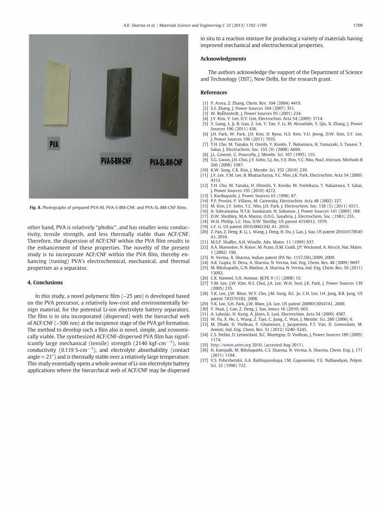
Fig. 8. Photographs of prepared PVA-M, PVA-S-BM-CNF, and PVA-SL-BM-CNF films.
1709A.K. Sharma et al. / Materials Science and Engineering C 33 (2013) 1702–1709
other hand, PVA is relatively “phobic”, and has smaller ionic conduc-tivity, tensile strength, and less thermally stable than ACF/CNF.Therefore, the dispersion of ACF/CNF within the PVA film results inthe enhancement of these properties. The novelty of the presentstudy is to incorporate ACF/CNF within the PVA film, thereby en-hancing (tuning) PVA's electrochemical, mechanical, and thermalproperties as a separator.
4. Conclusions
In this study, a novel polymeric film (~25 μm) is developed basedon the PVA precursor, a relatively low-cost and environmentally be-nign material, for the potential Li-ion electrolyte battery separators.The film is in situ incorporated (dispersed) with the hierarchal webof ACF/CNF (~500 nm) at the incipience stage of the PVA gel formation.The method to develop such a film also is novel, simple, and economi-cally viable. The synthesized ACF/CNF-dispersed PVA film has signif-icantly large mechanical (tensile) strength (2146 kgf-cm−2), ionicconductivity (0.119 S-cm−1), and electrolyte absorbability (contactangle=21°) and is thermally stable over a relatively large temperature.This study essentially opens awhole avenue of Li-ion electrolyte batteryapplications where the hierarchical web of ACF/CNF may be dispersed
in situ to a reaction mixture for producing a variety of materials havingimproved mechanical and electrochemical properties.
Acknowledgments
The authors acknowledge the support of the Department of Scienceand Technology (DST), New Delhi, for the research grant.
References
[1] P. Arora, Z. Zhang, Chem. Rev. 104 (2004) 4419.[2] S.S. Zhang, J. Power Sources 164 (2007) 351.[3] W. BoÈhnstedt, J. Power Sources 95 (2001) 234.[4] J.Y. Kim, Y. Lee, D.Y. Lim, Electrochim. Acta 54 (2009) 3714.[5] Y. Liang, L. Ji, B. Guo, Z. Lin, Y. Yao, Y. Li, M. Alcoutlabi, Y. Qiu, X. Zhang, J. Power
Sources 196 (2011) 436.[6] J.H. Park, W. Park, J.H. Kim, D. Ryoo, H.S. Kim, Y.U. Jeong, D.W. Kim, S.Y. Lee,
J. Power Sources 196 (2011) 7035.[7] T.H. Cho, M. Tanaka, H. Onishi, Y. Kondo, T. Nakamura, H. Yamazaki, S. Tanase, T.
Sakai, J. Electrochem. Soc. 155 (9) (2008) A699.[8] J.L. Gineste, G. Pourcelly, J. Membr. Sci. 107 (1995) 155.[9] S.G. Gwon, J.H. Choi, J.Y. Sohn, S.J. An, Y.E. Ihm, Y.C. Nho, Nucl. Instrum. Methods B
266 (2008) 3387.[10] K.W. Song, C.K. Kim, J. Membr. Sci. 352 (2010) 239.[11] J.Y. Lee, Y.M. Lee, B. Bhattacharya, Y.C. Nho, J.K. Park, Electrochim. Acta 54 (2009)
4312.[12] T.H. Cho, M. Tanaka, H. Ohnishi, Y. Kondo, M. Yoshikazu, T. Nakamura, T. Sakai,
J. Power Sources 195 (2010) 4272.[13] I. Kuribayashi, J. Power Sources 63 (1996) 87.[14] P.P. Prosini, P. Villano, M. Carewska, Electrochim. Acta 48 (2002) 227.[15] M. Kim, J.Y. Sohn, Y.C. Nho, J.H. Park, J. Electrochem. Soc. 158 (5) (2011) A511.[16] A. Subramania, N.T.K. Sundaram, N. Sukumar, J. Power Sources 141 (2005) 188.[17] D.W. Sheibley, M.A. Manzo, O.D.G. Sanabria, J. Electrochem. Soc. (1983) 255.[18] W.H. Phillip, L.C. Hsu, D.W. Sheilby, US patent 4154912, 1979.[19] L.F. Li, US patent 2010/0062342 A1, 2010.[20] Z. Pan, Z. Deng, R. Li, L. Wang, J. Deng, H. Du, J. Gao, J. Suo, US patent 2010/0178545
A1, 2010.[21] M.S.P. Shaffer, A.H. Windle, Adv. Mater. 11 (1999) 937.[22] A.A. Mamedov, N. Kotov, M. Prato, D.M. Guldi, J.P. Wicksted, A. Hirsch, Nat. Mater.
1 (2002) 190.[23] N. Verma, A. Sharma, Indian patent IPA No. 1157/DEL/2009, 2009.[24] A.K. Gupta, D. Deva, A. Sharma, N. Verma, Ind. Eng. Chem. Res. 48 (2009) 9697.[25] M. Bikshapathi, G.N. Mathur, A. Sharma, N. Verma, Ind. Eng. Chem. Res. 50 (2011)
13092.[26] C.K. Haweel, S.H. Ammar, IJCPE 9 (1) (2008) 15.[27] Y.M. Lee, J.W. Kim, N.S. Choi, J.A. Lee, W.H. Seol, J.K. Park, J. Power Sources 139
(2005) 235.[28] Y.K. Lee, J.W. Rhee, W.Y. Cho, J.M. Sung, B.C. Jo, C.H. Lee, I.H. Jung, B.R. Jung, US
patent 7435761B2, 2008.[29] Y.K. Lee, S.H. Park, J.W. Rhee, J.A. Lee, US patent 20090130547A1, 2009.[30] Y. Huai, J. Gao, Z. Deng, J. Suo, Ionics 16 (2010) 603.[31] A. Laheäär, H. Kurig, A. Jänes, E. Lust, Electrochim. Acta 54 (2009) 4587.[32] W. Pu, X. He, L. Wang, Z. Tian, C. Jiang, C. Wan, J. Membr. Sci. 280 (2006) 6.[33] M. Dhabi, D. Violleau, F. Ghamouss, J. Jacquemin, F.T. Van, D. Lemordant, M.
Anouti, Ind. Eng. Chem. Res. 51 (2012) 5240–5245.[34] C.S. Stefan, D. Lemordant, B.C. Montigny, D. Violleau, J. Power Sources 189 (2009)
1174.[35] http://www.astm.org 2010, (accessed Aug 2011).[36] H. Katepalli, M. Bikshapathi, C.S. Sharma, N. Verma, A. Sharma, Chem. Eng. J. 171
(2011) 1194.[37] V.S. Pshezhetskii, A.A. Rakhnyanskaya, I.M. Gaponenko, Y.E. Nalbandyan, Polym.
Sci. 32 (1990) 722.