preparation and anodizing of sicp/al composites...
TRANSCRIPT
Research ArticlePreparation and Anodizing of SiCp/Al Composites withRelatively High Fraction of SiCp
Bin Wang ,1,2 Shengguan Qu ,1,2 and Xiaoqiang Li 1,2
1Guangdong Key Laboratory for Processing and Forming of Advanced Metallic Materials, South China University of Technology,Guangzhou 510640, China2National Engineering Research Center of Near-Net-Shape Forming for Metallic Materials, South China University of Technology,Guangzhou 510640, China
Correspondence should be addressed to Shengguan Qu; [email protected]
Received 27 October 2017; Revised 31 December 2017; Accepted 29 January 2018; Published 26 February 2018
Academic Editor: Guosong Wu
Copyright © 2018 BinWang et al.This is an open access article distributed under the Creative CommonsAttribution License, whichpermits unrestricted use, distribution, and reproduction in any medium, provided the original work is properly cited.
By properly proportioned SiC particles with different sizes and using squeeze infiltration process, SiCp/Al composites with highvolume fraction of SiC content (Vp = 60.0%, 61.2%, 63.5%, 67.4%, and 68.0%) were achieved for optical application. The flexuralstrength of the prepared SiCp/Al composites was higher than 483MPa and the elastic modulus was increased from 174.2 to206.2GPa. With an increase in SiC volume fraction, the flexural strength and Poisson’s ratio decreased with the increase inelastic modulus. After the anodic oxidation treatment, an oxidation film with porous structure was prepared on the surface ofthe composite and the oxidation film was uniformly distributed. The anodic oxide growth rate of composite decreased with SiCcontent increased and linearly increased with anodizing time.
1. Introduction
The aluminum matrix composites reinforced by SiCp par-ticles have been extensively applied in industry for theirlow density and high specific strength. In recent years,these materials with high fraction of SiCp particle (>60%)are used in space mirror, owing to their excellent thermalconductivity and low coefficient of thermal expansion (CTE)[1]. SiCp/Al composite with relatively high SiC content areselected as structural substrates for a space mirrors [2]. Guoet al. [3] analyzed that the closer the glass and matrix ofthermal expansion coefficients between them, the better thecombination. Zhang et al. [4] prepared a plane mirror withan open back lightweight structure with SiCp/Al compos-ite with a light advantage. However, due to high volumefraction SiCp/Al with high hardness and low plasticity, it isdifficult to machine this kind of material to achieve highsurfacemicroroughness; otherwise it cannot reach the opticalfunction [5]. At present, the glass coating technique, whichhas been taken as an important modification techniqueto bond the glass on the SiCp/Al composite surface, has
attracted more interest, because the higher polishability ofthe SiCp/Al composite surface can be obtained by using thistechnique [6, 7]. Compounding optical glass and compositesimproves the polishing properties of the composites [8]. Inorder to obtain a high profile and surface roughness, themirror is polished by using the ultrasmooth polishing. Severalresearchers have attempted to overcome the bonding strengthbetween metal and glass. Chanmuang et al. [9] prepared theborosilicate glass-to-Kovar joint by bonding glass to the alloy,and the joint has a bonding strength of 4.3MPa. Joining waspreformed by fusion of the glass, which wetted the alloy,at 1000∘C after 15min in the electric furnace. In traditionalprocess, compounding of composite and glass is operatedunder high temperature. If we adopt the anodic oxidationtechnology, the binding temperature can be reduced. It issignificant to save energy.
The bonding strength of SiCp/Al composite-glass compo-nents plays an important role in the reliability. The bondingproperty at glass/metal interface is deemed as the key bench-mark for assessing the quality of the space mirror, becauseit will be posited in the harsh serving condition. Mantel
HindawiScanningVolume 2018, Article ID 8945729, 13 pageshttps://doi.org/10.1155/2018/8945729
2 Scanning
Table 1: Chemical composition of 6061-Al.
Specification Composition (wt %)Cu Mg Fe Si Zn Mn Pb Al
Aluminum alloy 0.258 1.08 0.255 0.962 0.24 0.168 0.09 96.947
Table 2: The properties of the prepared SiCp/Al composites. 𝐷 is the average diameter of the mixed powders used in this work, 𝑉𝑝 is thevolume fraction of SiC particles, 𝜎𝑏𝑏 is the flexural strength of the composites, 𝐸 is the elastic modulus of the composites, and 𝛾 is Poisson’sratio of the composites.
Gradation composition(𝜇m) and proportion
𝐷𝜇m
𝑉𝑝(%)
𝜎𝑏𝑏(MPa) 𝛾
𝐸 (GPa)Measured/Wu (%) Measured/H-S (%)Measured
dataWu
modelH-Smodel
45 : 8 : 2 = 1000 : 100 : 400 34.63 68.0 483 0.28 206.1 245.1 271.7 84 7645 : 8 : 2 = 1000 : 200 : 300 36.69 67.4 544 0.33 195.8 243.3 269.8 80 7345 : 8 : 2 = 1000 : 250 : 250 37.38 63.5 548 0.35 195.7 231.9 257.7 84 7645 : 8 : 2 = 1000 : 300 : 200 39.74 61.2 554 0.35 180.8 225.6 251.0 80 7245 : 8 : 2 = 1000 : 400 : 100 44.87 60.0 569 0.36 174.2 222.5 247.5 78 70
[10] indicated the initially prepared oxidation film at theglass/metal interface was favorable to enhance the bondingproperty.
As far as Al matrix composite, it is well known thatthe thickness of alumina film under natural condition isonly several nanometers, which is difficult to form a stablemetal/glass bonding interface. After the anodizing process onthe SiCp/Al substrate, an oxidation film with thick enoughdimension on the surface of aluminum could be obtained.Aluminum is a potential candidate metal for forming anoxidation film with substantial thickness on its surface.However, the aluminum layer on the exposed surface of Alingot is too thin to satisfy the demand of promoting thebonding property at glass/metal interface. In the past decades,techniques such as anodizing and microarc oxidation wereproposed for anticorrosion of Al substrate. Anodizing isan effective and commercial method for obtaining a thickoxidation film on Al surface, which is also suitable for theindustrial mass production.
So far, there have been few reports about anodizedSiCp/Al composite, even less high volume fraction SiCp/Alcomposite. Because the local melt structure around SiCparticle affects the microstructures of the composites and theproperties of the interface [11], compounding temperaturemust be lower than the solution temperature of the matrix.However, researchers have paid little attention to the meltingpoint of anodized high volume fraction SiCp/Al composites.In order to obtain a perfect combination of compositeand glass, the effect of the anodizing process on the oxidegrowth rates of composites and the solution temperatureof composites needs to be investigated. For the aerospaceapplication, combination of glass and alloywas often achievedat relatively high temperature 1000∘C after 15min in theelectric furnace. In our previous work [12], the glass was com-bined to the SiCp/Al composite matrix with high content SiCparticles with 45 𝜇m, 8 𝜇m, and 2 𝜇m addition by preparingan alumina layer on the surface of SiCp/Al composite in theelectric furnace. Selecting an optical grade SiCp/Al compositewith high SiC content as a space mirror material is propitious
to promote the integration of the mirror and its supportingstructure. However, till date, few reports are concerned withcombining the glass on the Al matrix with high additionof SiC particles with vacuum hot-pressing compound. As anovel structural material for aerospace, composites have topossess goodmechanical properties when the aerospace partsare in the service conditions of rapid cooling and heating,such as with high dimensional stability, high elastic modulus,and low Poisson’s ratio.
2. Experiment
2.1. Materials and Procedures. The chemical compositions ofthe Al matrix are listed in Table 1. The green 𝛼-SiC (6H)powder with a purity of 99.9%was used in this experiment. Inorder to obtain the SiCp/Al composites with high SiCp frac-tions, the particles with themedian diameters of 45𝜇m, 8 𝜇m,and 2𝜇m were ball-milled for 10 h and then homogenouslymixed at room temperature. The size distribution, tested byMalvern laser particle size analyzer, of the particles after ballmilling process was given in Table 2.
A hydraulic machine was carried out for the preparationof SiCp preform. In this process the mixed SiCp powder wascompacted in a cylindrical graphite mold under a pressure of25MPa.Thereafter, the preformwas sintered at 1600∘C for 2 hand cooled down to room temperature in the atmosphere.
The SiCp/Al composite was manufactured by using thesqueeze casting machine. The prepared preform was pre-heated to 700∘C in a steel mold. The molten Al (superheatedto 820∘C) was infiltrated to the steel mold by applying thehydraulic pressure from 8 to 90MPa. The steel mold wascooled down to the room temperature when the infiltrationprocess was completed.
The formed SiCp/Al composites were machined into thestandard tensile and flexural specimens according to GB/T228.1-2010 and GB/T 232-2010, respectively.
Flexural samples were also fabricated according to thestandard of GB/T 232-2010. The dimension for the flexuralsample was 65mm × 7mm × 7mm. The parallelepiped
Scanning 3
Gauge length
Mark line
R12
10 6 2
15
45
(a)
65 7 × 7
(b)
Figure 1: The schematic of tensile and flexural specimen size and the photo of test sample.
samples wasmachinedwith the size of 8mm× 8mm× 8mm.The parallelepiped samples were used for anodizing process.Before anodizing operation, the samples was etched in KOHsolution (50 g/L) at room temperature for 2min. Thereafter,it was rinsed in distilled water. Chemical pickling processwas carried out in terms of HNO3 solution (1mol/L) at roomtemperature for 3min. Again, the sample was cleaned bydistilled water and dried in a drying oven. The anodizingelectrolyte was sulfuric acid. The sulfuric acid concentra-tion was 180 g/L; the polar distance was 3 cm; the anodiccurrent density was 1.6 A. An aluminum alloy plate wasused as the cathode materials. Sulfuric and nitric acids wereanalytical grade chemicals. Different anodic oxidation timeswere employed in order to obtain different thickness of theoxidation film. The time durations for the anodizing processwere independently set at 5min, for 10min, for 15min,for 20min, for 25min, and for 30min. The parallelepipedsamples were mechanically ground P 1500 grade paper andthen polished.
2.2. TestingMethods and Characterization. In order to obtaina better interface bonding strength, high volume fractionSiCp/Alwas anodized prior to vacuumhot-pressing. Two setsof strain gauges that scatter in orthogonal planes were stuckon the tensile specimens. The gauge length was marked onthe surface of the tensile specimens (Figure 1). The strainsof the specimens were tested at room temperature on aMTS test machine. Based on strain measurements of thecomposites, Poisson’s ratio of the composites was calculated.
By measuring the change in the length of tensile sampleand the cleavage fracture stress, the elastic modulus of thecomposites was calculated. The flexural strengths of thesamples were tested at room temperature on a MTS testmachine. The test method is a three-point bending test.The micromorphologies of the mixed SiC particles and thefracture surface of tensile samples and flexural samples wereobserved by a NOVA NANOSEM 430 scanning electronmicroscope (SEM).
X-ray diffraction (XRD) analysis of the parallelepipedsamples was carried out on a SIEMENS D8 ADVANCEdiffractometer using Cu radiation. Electron backscattereddiffraction (EBSD) was used to evaluate the oxide layers ofthe samples. The oxygen content in the anodized sampleswas analyzed by Energy Dispersive Spectrometer (EDS).The parallelepiped samples were sputtered with platinumfor 70 seconds to characterization. SEM was employed toobserve themicrostructure of the anodic film.ThedifferentialScanning Calorimetry (DSC) measured the endothermicpeak of the composites. The heating rate was 5∘C/min. TheDSC scanning was initiated at 30∘C and completed at 750∘C.
3. Results and Analysis
3.1. Mechanical Properties of Composites
3.1.1. Flexural Strength. Testing results in Table 2 show thatthe flexural strengths of composites are 569, 554, 548, 544,and 483MPa for the 60.0%, 61.2%, 63.5%, 67.4%, and 68.0%

4 Scanning
Table 3: The properties of SiC particles and aluminum alloy atroom temperature. 𝜎𝑏𝑏, 𝐸, and 𝛾 represent flexural strength, elasticmodulus, and Poisson’s ratio, respectively.
Specification 𝜎𝑏𝑏 𝐸 𝛾(MPa) (GPa)
SiC 550 410 0.14Aluminum alloy 398a 130.1a 0.40aaExperimental data.
composites, respectively. The flexural strength of the matrixis 398MPa (Table 3 for the properties of aluminum alloy),and the flexural strength of the SiC is 550MPa. The flexuralstrength of the composites is greater than the flexural ofthe matrix; even the flexural strengths of 60% and 61.2%composites are higher than the flexural strength of SiC. Thisindicates remarkable enhancement in flexural strength ofcomposites with an addition of SiC particles.
The effect of SiC content to the flexural strength ofcomposites is presented in Figure 2(a). It is observed inFigure 2(a) that the flexural strengths of composites have aclear tendency to decrease with the increase of SiC particlevolume fraction; in particular the flexural strength producedat a rapid decrease in the value of SiC content from 67.4% to68.0%. This can be ascribed to two reasons: on the one hand,the higher the volume fraction of SiC particle and the smallerthe size of SiC particle the easier the agglomeration of SiCparticles [13, 14]. In this experiment, composites are preparedwith the mixture of SiC particles infiltration in molten alu-minum.Themean grain sizes of SiC particle are 45𝜇m, 8𝜇m,and 2 𝜇m.The size of SiC particle mixture is refined after ballmilling. It is clearly seen from Figure 3(a) (white arrow) thatthere are many fine particles in the mixture, and these fineparticles cluster together. Some fine particles are very fine,with sizes reaching nanometers (Figure 3(b)). Figure 3(b)shows that the fine particles can form agglomeration easily.The agglomeration of fine particles prevents the infiltrationof molten aluminum into a SiC preform and results in adegradation of the interface bonding performance betweenSiC andmatrix.The stress transfer at the SiC-matrix interfacebecomesmore inefficient with the increase of SiC content. So,the flexural strengths of composites decrease with increasingparticle loading. Another reason is related to the brittleness ofSiC. Composites will become more brittle with the increaseof SiC particle content. The increase of brittleness causes adecline in the flexural strength of composites [15].
Testing data in Table 2 indicates that the mean grain sizesof SiC particles in composites are 44.87, 39.74, 37.38, 36.39,and 34.63 𝜇m for the 60.0%, 61.2%, 63.5%, 67.4%, and 68.0%composites, respectively. The effect of SiC particle size onthe flexural strengths of composites is shown in Figure 2(c).As depicted in Figure 2(c), for smaller mean grain size ofSiC particles (34.63–37.38 𝜇m), there is a prompt increasein the flexural strength with increasing particle sizes. Forlarger mean grain sizes of SiC particles (39.74–44.87 𝜇m),the increase in the flexural strength is no longer significant.The results imply that SiC particle size has an effect onSiC-matrix interface adhesion. The mean grain size of SiC
particles is related to the content of 2 𝜇m particles. Withthe content of 2 𝜇m particle decreasing, the content of fineparticles decreases, and the agglomeration of SiC particlesreduces. Desirable infiltration results can be obtained duringsqueezingmolten aluminum into SiC preform.This enhancesthe interfacial property of SiC-matrix and improves theflexural strength of composites.
3.1.2. Elastic Modulus. The measured elastic modulus ofcomposites was reported in Table 2 as 174.2, 180.8, 195.7, 195.8,and 206.1 GPa for the 60.0%, 61.2%, 63.5%, 67.4%, and 68.0%composites, respectively.The effect of SiC volume fraction onthe elastic modulus of composites is shown in Figure 2(b).It can be observed in Figure 2(b) that the elastic modulusof composites increases linearly with increasing SiC content,indicating that increasing the volume fraction of SiC particlescan improve the elastic modulus of composites. When theSiC-matrix interfacial adhesion is strong, the stress transfer atSiC-matrix interface is efficient.The effect of SiC particle sizeon the elastic modulus of composites is shown in Figure 2(d).As depicted in Figure 2(d), for larger mean grain size ofSiC particles (34.63–39.74 𝜇m), there is a prompt decrease inthe elastic modulus with increasing particle sizes. For largermean grain sizes of SiC particles 44.87 𝜇m, the increase inthe flexural strength is no longer significant. Under effectivestress transfer, the strength of composites will improve withthe increase of SiC content, but the strain in the longitudinaland composites will decrease. So, the elastic modulus ofcomposites increases with increasing SiC content.
3.1.3. Poisson’s Ratio. Poisson’s ratios of composites are 0.36,0.35, 0.35, 0.33, and 0.28 for the 60.0%, 61.2%, 63.5%,67.4%, and 68.0% composites, respectively. The effect of SiCvolume fraction on Poisson’s ratio of composites is shown inFigure 2(e), in which Poisson’s ratio of composites decreaseswith the increase of SiC volume fraction. The decrease ofPoisson’s ratio with the increase of SiC content is primarilydue to the difference in property of SiC andmatrix.The elasticmodulus of SiC particle is greater than that of the matrix; andPoisson’s ratio of SiC particles is lower than that of thematrix.The effect of SiC particle size on Poisson’s ratio of compositesis shown in Figure 2(f). As depicted in Figure 2(f), for largermean grain size of SiC particles (34.63–39.74 𝜇m), there isa prompt increase in Poisson’s ratio with increasing particlesizes. For larger mean grain sizes of SiC particles 44.87 𝜇m,the increase in Poisson’s ratio is no longer significant. Thisresists the negative strain of the matrix in the transversedirection [16]. So, Poisson’s ratio of composites with higherSiC content is less than Poisson’s ratio of composites withlower SiC content.
3.1.4. Fracture Behavior. Figure 4(a) is the SEM fractographfor the fracture sample of 68.0% composites. The fracturesurface of composites in Figure 4(a) is very rough. Thefracture surface appearance of SiC particles presents variety,such as steps, crack, and mirror. The result indicates that thedominant fracture mechanism of composites is a cleavagefracture arising from crack propagation. The fracture ofcomposites appears to have an obvious brittle character.

Scanning 5
Flexural strength
0.625 0.650 0.6750.600Volume fraction (%)
0
78
156
234
312
390
468
546
624
bb
(MPa
)
(a)
H-S modelWu modelMeasured elasticity modulus
0
84
168
252
336
420
E (G
Pa)
0.625 0.650 0.6750.600Volume fraction (%)
(b)
Flexural strength
36.1 38.0 39.9 41.8 43.7 45.634.2Mean grain size (m)
78
156
234
312
390
468
546
624
702
bb
(MPa
)
(c)
Measured elasticity modulus
36.3 39.6 42.933.0Mean grain size (m)
48
72
96
120
144
168
192
216
240E
(GPa
)
(d)
Poisson’s ratio
0.625 0.650 0.6750.600Volume fraction (%)
0.05
0.10
0.15
0.20
0.25
0.30
0.35
0.40
0.45
0.50
Poiss
on’s
ratio
(e)Poisson’s ratio
36.3 39.6 42.933.0Mean grain size (m)
0.05
0.10
0.15
0.20
0.25
0.30
0.35
0.40
0.45
0.50
Poiss
on’s
ratio
(f)
Figure 2: (a) Effect of SiC vol.% on flexural strength, (b) effect of SiC vol.% on elastic modulus, (c) effect of mean grain size on flexuralstrength, (d) effect of mean grain size on measured elasticity modulus, (e) effect of SiC vol.% on Poisson’s ratio, and (f) effect of mean grainsize on Poisson’s ratio.

6 Scanning
-;A = 5.00 × 100 m
(a)
-;A = 5.00+ × 100 m
(b)
Figure 3: (a) SEM images of the mixture SiC particle (gradation composition and proportion 45𝜇m : 8 𝜇m : 2 𝜇m = 1000 : 250 : 250) and (b)high magnification image of the framed area in (a).
-;A = 200 × 10 m
(a)
-;A = 3.00+ × 2m
(b)
-;A = 5.00+ × 3m
(c)
Figure 4: Fracture morphology of SiCp/Al composites. (a) The flexural fracture of the composite containing 68.0% SiCp, (b) highmagnification image of the framed area in (a), and (c) high magnification image of the framed area in (b).
Figure 4(b) is highly magnified images of the framed areain Figure 4(a). Figure 4(b) exhibits the interfacial adhesionbetween SiC particle and matrix is perfectly bonded. Thereis no debonding between the interface, SiC particle, andmatrix in good fusion. The results reveal that the interfacialbonding strength between SiCparticle andmatrix is high [17].Figure 4(c) is high magnification image of the framed areain Figure 4(b). Figure 4(c) shows that there is an extensivedimple pattern in the local composite. It can be observed thatthe dimple sizes in the composite are less than 5 𝜇m. The
dimples are associated with SiC particle size. Since there isincomplete infiltrating, the interfacial adhesion between fineparticles and matrix is not perfect. Debonding will occur atthe interface between fine particles and the matrix under thelocal stress concentrations. With ductile crack propagation,the void nucleation grows and finally coalesces. This resultsin dimple formation. Dimples on the composites show thatductile fracture occurs in the local composites during thebreaking process of the composites. However, no dislocationis observed near crack tip in Figure 4(c). It can be concluded
Scanning 7
Nonoxidizable 61.2% composite
Nonoxidizable 60.0% composite
Nonoxidizable 63.5% composite
Nonoxidizable 67.4% composite
Nonoxidizable 68.0% composite
#O!F2
SiCAl
36.6 42.7 48.8 54.9 61.0 67.1 73.2 79.330.5
Two theta (degrees)
0
2300
4600
6900
9200
11500
13800
16100
18400
Inte
nsity
(a.u
.)
(a)
Anodized 61.2% composite
Anodized 60.0% composite
Anodized 63.5% composite
Anodized 67.4% composite
Anodized 68.0% composite
36.6 42.7 48.8 54.9 61.0 67.1 73.2 79.330.5
Two theta (degrees)
0
1800
3600
5400
7200
9000
10800
12600
14400
Inte
nsity
(a.u
.)
SiCAl!F2/3
#O2/
(b)
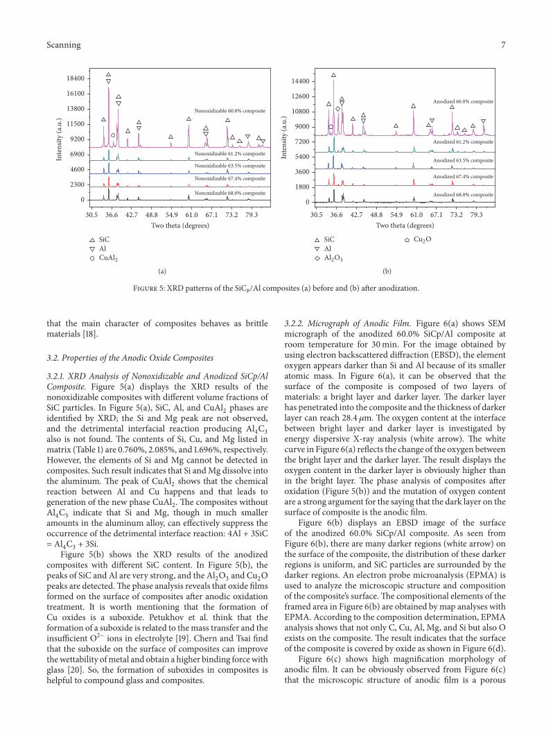
Figure 5: XRD patterns of the SiCP/Al composites (a) before and (b) after anodization.
that the main character of composites behaves as brittlematerials [18].
3.2. Properties of the Anodic Oxide Composites
3.2.1. XRD Analysis of Nonoxidizable and Anodized SiCp/AlComposite. Figure 5(a) displays the XRD results of thenonoxidizable composites with different volume fractions ofSiC particles. In Figure 5(a), SiC, Al, and CuAl2 phases areidentified by XRD; the Si and Mg peak are not observed,and the detrimental interfacial reaction producing Al4C3also is not found. The contents of Si, Cu, and Mg listed inmatrix (Table 1) are 0.760%, 2.085%, and 1.696%, respectively.However, the elements of Si and Mg cannot be detected incomposites. Such result indicates that Si andMg dissolve intothe aluminum. The peak of CuAl2 shows that the chemicalreaction between Al and Cu happens and that leads togeneration of the new phase CuAl2. The composites withoutAl4C3 indicate that Si and Mg, though in much smalleramounts in the aluminum alloy, can effectively suppress theoccurrence of the detrimental interface reaction: 4Al + 3SiC= Al4C3 + 3Si.
Figure 5(b) shows the XRD results of the anodizedcomposites with different SiC content. In Figure 5(b), thepeaks of SiC and Al are very strong, and the Al2O3 and Cu2Opeaks are detected.The phase analysis reveals that oxide filmsformed on the surface of composites after anodic oxidationtreatment. It is worth mentioning that the formation ofCu oxides is a suboxide. Petukhov et al. think that theformation of a suboxide is related to themass transfer and theinsufficient O2− ions in electrolyte [19]. Chern and Tsai findthat the suboxide on the surface of composites can improvethewettability ofmetal and obtain a higher binding forcewithglass [20]. So, the formation of suboxides in composites ishelpful to compound glass and composites.
3.2.2. Micrograph of Anodic Film. Figure 6(a) shows SEMmicrograph of the anodized 60.0% SiCp/Al composite atroom temperature for 30min. For the image obtained byusing electron backscattered diffraction (EBSD), the elementoxygen appears darker than Si and Al because of its smalleratomic mass. In Figure 6(a), it can be observed that thesurface of the composite is composed of two layers ofmaterials: a bright layer and darker layer. The darker layerhas penetrated into the composite and the thickness of darkerlayer can reach 28.4𝜇m. The oxygen content at the interfacebetween bright layer and darker layer is investigated byenergy dispersive X-ray analysis (white arrow). The whitecurve in Figure 6(a) reflects the change of the oxygen betweenthe bright layer and the darker layer. The result displays theoxygen content in the darker layer is obviously higher thanin the bright layer. The phase analysis of composites afteroxidation (Figure 5(b)) and the mutation of oxygen contentare a strong argument for the saying that the dark layer on thesurface of composite is the anodic film.
Figure 6(b) displays an EBSD image of the surfaceof the anodized 60.0% SiCp/Al composite. As seen fromFigure 6(b), there are many darker regions (white arrow) onthe surface of the composite, the distribution of these darkerregions is uniform, and SiC particles are surrounded by thedarker regions. An electron probe microanalysis (EPMA) isused to analyze the microscopic structure and compositionof the composite’s surface.The compositional elements of theframed area in Figure 6(b) are obtained by map analyses withEPMA. According to the composition determination, EPMAanalysis shows that not only C, Cu, Al, Mg, and Si but also Oexists on the composite. The result indicates that the surfaceof the composite is covered by oxide as shown in Figure 6(d).
Figure 6(c) shows high magnification morphology ofanodic film. It can be obviously observed from Figure 6(c)that the microscopic structure of anodic film is a porous
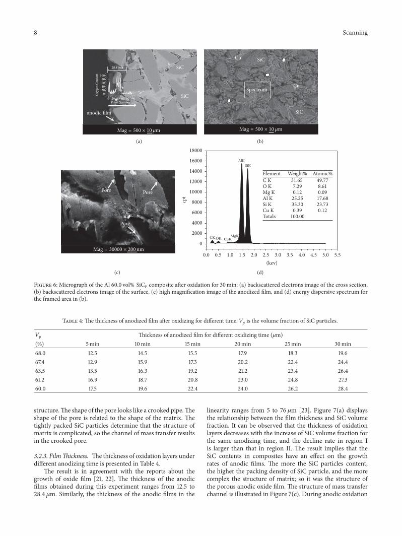
8 Scanning
anodic film
SiC
SiC
-;A = 500 × 10 m
20 40 60 80 1000Point Number
020406080
100
28.4 m
Oxy
gen
Con
tent
(a)
SiC
SiC
Spectrum Cu
Cu
-;A = 500 × 10 m
(b)
Pore
Pore Pore
-;A = 30000 × 200nm
(c)
cpt
SiKAlK
MgKCuKOKCK
Element Weight% Atomic%C K 31.65 49.77O K 7.29 8.61Mg K 0.12 0.09Al K 25.25 17.68Si K 35.30 23.73Cu K 0.39 0.12Totals 100.00
0.5 1.0 1.5 2.0 2.5 3.0 3.5 4.0 4.5 5.0 5.50.0(kev)
0
2000
4000
6000
8000
10000
12000
14000
16000
18000
(d)
Figure 6: Micrograph of the Al 60.0 vol% SiCP composite after oxidation for 30min: (a) backscattered electrons image of the cross section,(b) backscattered electrons image of the surface, (c) high magnification image of the anodized film, and (d) energy dispersive spectrum forthe framed area in (b).
Table 4: The thickness of anodized film after oxidizing for different time. 𝑉𝑝 is the volume fraction of SiC particles.
𝑉𝑝 Thickness of anodized film for different oxidizing time (𝜇m)(%) 5min 10min 15min 20min 25min 30min68.0 12.5 14.5 15.5 17.9 18.3 19.667.4 12.9 15.9 17.3 20.2 22.4 24.463.5 13.5 16.3 19.2 21.2 23.4 26.461.2 16.9 18.7 20.8 23.0 24.8 27.360.0 17.5 19.6 22.4 24.0 26.2 28.4
structure.The shape of the pore looks like a crooked pipe.Theshape of the pore is related to the shape of the matrix. Thetightly packed SiC particles determine that the structure ofmatrix is complicated, so the channel of mass transfer resultsin the crooked pore.
3.2.3. FilmThickness. The thickness of oxidation layers underdifferent anodizing time is presented in Table 4.
The result is in agreement with the reports about thegrowth of oxide film [21, 22]. The thickness of the anodicfilms obtained during this experiment ranges from 12.5 to28.4𝜇m. Similarly, the thickness of the anodic films in the
linearity ranges from 5 to 76𝜇m [23]. Figure 7(a) displaysthe relationship between the film thickness and SiC volumefraction. It can be observed that the thickness of oxidationlayers decreases with the increase of SiC volume fraction forthe same anodizing time, and the decline rate in region Iis larger than that in region II. The result implies that theSiC contents in composites have an effect on the growthrates of anodic films. The more the SiC particles content,the higher the packing density of SiC particle, and the morecomplex the structure of matrix; so it was the structure ofthe porous anodic oxide film. The structure of mass transferchannel is illustrated in Figure 7(c). During anodic oxidation

Scanning 9
Region II
Thic
knes
s (
m)
Region I
0.62 0.64 0.66 0.680.60SiC volume fraction (%)
5 min10 min15 min
20 min25 min30 min
0
5
10
15
20
25
30
(a)Th
ickn
ess (
m
)
Region IVRegion III
5 10 15 20 25 300Time (min)
0
5
10
15
20
25
30
68.0% SiCp/Al67.4% SiCp/Al63.5% SiCp/Al
61.2% SiCp/Al60.0% SiCp/Al
(b)
Channel of mass transfer
Anodic film
SiCp/Al
(c)
Figure 7: The relationship (a) between the anodic film thickness and SiC volume fraction and (b) between the anodic film thickness andanodizing time. (c) The schematic of mass transfer channel.
of composites, the growing anodic films need a continuousdelivery of oxygen [24]. The growth of the anodic films isdetermined by the transfer velocity of ion across the matrix-oxide interface [25]. Because of the complex structure, themass transfer channel obstructs the flow of electrolytes, andthis results in a reduction of the mas transfer velocity andthe decline in the growth rates of anodic films. The 2𝜇m SiCparticle content of 68% composite is more than that of 67.4%of the composite.The increase of 2𝜇mSiC particle acceleratescomplication of the mass transfer channel’s structure. So, theflow resistance of electrolytes increases sharply. As a result,the growth rate of anodic films decreases significantly. Therelationship between the thickness of anodic films and timeis shown in Figure 7(b). From Figure 7(b), it is clear thatfilm growth is consistent with the rising stage (region III)and the stable stage (region IV). The film growth rate of therising stage is greater than that of the stable stage. At thesame time, the film thickness-time relationship reveals thatthe anodic films grow linearly with time during the stablestage. The result implies that there is dynamic equilibriumbetween oxidation and chemical dissolution. The dynamicequilibrium of the oxide formation and dissolution causes
that the growth rates of anodic films are a constant. Thethickness of SiCp/Al content 68.0% micrograph was shownin Figure 8.
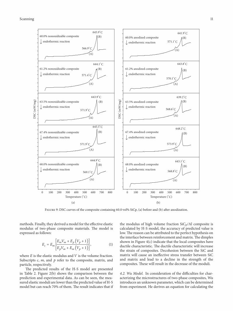
3.2.4. The Melting Point of Composites. The DSC thermo-grams of nonoxidizable and anodized composites obtainedare shown in Figures 9(a) and 9(b), respectively. It is foundthat the curves in both Figures consist of similar principlefeatures and heat effects are the two endothermic peaks, (A)and (B). The endothermic peak (A) is due to the dissolutionof CuAl2, and the endothermic peak (B) is attributed to thedissolution of the matrix alloy [26]. The peak temperatures(A and B) are shown in Figures 9(a) and 9(b). The data inFigures 9(a) and 9(b) show the following: (1) the endothermicpeaks (A) of all nonoxidizable composites and anodizedcomposites are near 570∘C, and the endothermic peaks (B)of all nonoxidizable composites and anodized composites arenear 640∘C. During compounding optical glass and com-posites, the preheat temperature must be based on peak (A)temperature. (2) SiC content and anodic films on the surfaceof composites have a negligent effect on the endothermicpeaks of composites.

10 Scanning
Oxidelayer
50 m
(a)
Oxidelayer
50 m
(b)
50 m
Oxidelayer
(c)
50 m
Oxidelayer
(d)
50 m
Oxidelayer
(e)
50 m
Oxidelayer
(f)
Figure 8: SEM micrograph of 68.0% SiCp/Al composite after being anodized with different time.
4. Discussions
At present, a number of scholars have applied microme-chanics theory to study the quantitative relationship betweenthe properties of composites and the properties of its con-stituents, and established the mathematical model, such asthe Hashin-Shtrikman model [27] (H-S model) and theWu model [28]. By comparing the predicted results withthe model with experimental results, the rationality of themodel can be studied. However, the accuracy of thesemodels on predicting the elastic modulus of high volumefraction SiCP/Al composites is rare in reports, let alonemodel validation.The advance of the present composite is thefabrication process, which consisted of mixing SiC particles,sintering process design, prefrom quality traceability, pre-heating prefrom,melting aluminum, and squeeze infiltrating.
The new process differs from the traditional process, whichcan decrease the rejection rate and cost. The developmentof SiCp/Al composite is integration of material and processdevelopment with system design andmanufacturing process,which provides an approach to obtain the maximum benefitfrom the characteristics offered by a new material [29].
4.1. Hashin-Shtrikman Model. Hashin and Shtrikman con-sider the strain, interface bonding, and stress transferbetween reinforcement and matrix. They assume that thestrain cross section of the composite under uniaxial loadingis uniform, the interface bonding between particle-matrix isperfect, and stress transfer between reinforcement andmatrixis effective. They have grouped many analysis methods, suchas direct methods, variation methods, and approximation
Scanning 11
645.9∘#
566.9∘#
644.1∘#
571.4∘#
643.9∘#
571.9∘#
645.5∘#
571.9∘#
60.0% nonoxidizable composite
endothermic reaction
61.2% nonoxidizable composite
endothermic reaction
63.5% nonoxidizable compositeendothermic reaction
67.4% nonoxidizable compositeendothermic reaction
68.0% nonoxidizable compositeendothermic reaction
644.9∘#
569.1∘#
(A)
(A)
(A)
(A)
(A)
(B)
(B)
(B)
(B)
(B)
DSC
(mW
/mg)
100 200 300 400 500 600 700 8000
Temperature (∘#)
(a)
641.9∘#
571.1∘#
643.8∘#
570.1∘#
639.2∘#
568.6∘#
648.2∘#
573.9∘#
643.1∘#
568.8∘#
60.0% anodized compositeendothermic reaction
61.2% anodized composite
endothermic reaction
63.5% anodized compositeendothermic reaction
67.4% anodized composite
endothermic reaction
68.0% anodized compositeendothermic reaction
(A)
(A)
(B)
(B)
(A)
(A)
(A)
(B)
(B)
(B)
DSC
(mW
/mg)
600500400 700 800300100 2000
Temperature (∘#)
(b)
Figure 9: DSC curves of the composite containing 60.0 vol% SiCp, (a) before and (b) after anodization.
methods. Finally, they derived amodel for the effective elasticmodulus of two-phase composite materials. The model isexpressed as follows:
𝐸𝑐 = 𝐸𝑚[𝐸𝑚𝑉𝑚 + 𝐸𝑝 (𝑉𝑝 + 1)][𝐸𝑝𝑉𝑚 + 𝐸𝑚 (𝑉𝑝 + 1)]
, (1)
where 𝐸 is the elastic modulus and 𝑉 is the volume fraction.Subscripts 𝑐, 𝑚, and 𝑝 refer to the composite, matrix, andparticle, respectively.
The predicted results of the H-S model are presentedin Table 2. Figure 2(b) shows the comparison between theprediction and experimental data. As can be seen, the mea-sured elasticmoduli are lower than the predicted value ofH-Smodel but can reach 70% of them.The result indicates that if
the modulus of high volume fraction SiCP/Al composite iscalculated by H-S model, the accuracy of predicted value islow.The reason can be attributed to the perfect hypothesis onthe interface between reinforcement andmatrix.The dimplesshown in Figure 4(c) indicate that the local composites haveductile characteristic. The ductile characteristic will increasethe strain of composites. Decohesion between the SiC andmatrix will cause an ineffective stress transfer between SiCand matrix and lead to a decline in the strength of thecomposites. These will result in the decrease of the moduli.
4.2. Wu Model. In consideration of the difficulties for char-acterizing the microstructures of two-phase composites, Wuintroduces an unknown parameter, which can be determinedfrom experiment. He derives an equation for calculating the
12 Scanning
effective elastic modulus of composites. Wu’s equation can bewritten as follows:
1𝐸𝑐 =[[1𝐸𝑚 −
(1/𝐸𝑚 − 1/𝐸𝑝)2𝜆 (1/𝐸𝑚 − 𝑉𝑚/𝑉𝑝𝐸𝑚)
]]𝑉𝑚 +𝑉𝑝𝐸𝑝 , (2)
where 𝐸 is the elastic modulus, 𝑉 is volume fraction, 𝜆 is theunknownparameter (𝜆 = 20), and subscripts 𝑐,𝑚, and𝑝 referto the composite, matrix, and particle, respectively.
The calculated data from the Wu model are listed inTable 2. By contrasting measured data with forecasting value,it can be found that the Wu model values are also higherthan the measured moduli. However, the measured elasticmodulus can reach 78% the prediction of the Wu model,indicating thatWumodel is more practical for the predictionof high volume fraction composites’ modulus. It is due to theunknown parameter (𝜆) that can fit the experimental data.
5. Conclusions
In the present study, the mechanical and anodized surfaceproperties of high volume fraction SiCP/Al composite havebeen investigated, and the accuracy of theoretical modelin predicting the elastic modulus of high volume fractioncomposites also has been verified. The following results areobtained.
Si andMg are added in smaller amounts to the aluminumalloy, effectively suppressing the formation of Al4C3. Withan increase in SiC volume fraction, the flexural strength andPoisson’s ratio decrease while the elastic modulus increases.With the mean grain size increasing, the flexural strengthincreases. From the fracture feature, it is found that thedominant fracture mechanism of composites is a cleavagefracture with occurrence of ductile fracture in the local ofcomposites.
Through anodic oxidation treatment, an oxidation filmwith porous structure can be prepared on the surface ofthe composites. The anodic film is uniformly distributed.The oxide growth rate of composites linearly increases withanodizing time and decreases with SiC content increasing.SiC content and anodic films on the surface of compositeshave a negligent effect on the endothermic peaks of thecomposites.
The measured elastic modulus is in good agreement withpredicted values based on Wu’s model.
Conflicts of Interest
The authors declare that there are no conflicts of interestregarding the publication of this paper.
Acknowledgments
This studywas funded by theNationalMajor Project of China(JCKY2016208A002). All investigations were performed inthe Advanced Materials Processing Laboratory at SouthChina University of Technology.
References
[1] J. H. Burge, D. Baiocchi, and B. Cuerden, “Ultralightweightactive mirror technology at the University of Arizona,” inProceedings of the Optomechanical Engineering 2000, pp. 230–241, November 2000.
[2] S. Guo, L. Li, G. Zhang, W. Wang, and X. Zhao, “Stress analysisat the interface between Ni-P coating and SiCp/Al substrate ofspace mirror,” Applied Surface Science, vol. 255, no. 6, pp. 3691–3695, 2009.
[3] S. Guo, G. Zhang, L. Li, W. Wang, and X. Zhao, “Effect ofmaterials and modelling on the design of the space-basedlightweight mirror,” Materials and Corrosion, vol. 30, no. 1, pp.9–14, 2009.
[4] Y. Zhang, J. Zhang, J. Han, X. He, and W. Yao, “Large-scalefabrication of lightweight Si/SiC ceramic composite opticalmirror,”Materials Letters, vol. 58, no. 7-8, pp. 1204–1208, 2004.
[5] R. S. Breidenthal, R. Galat-Skey, and J. J. Geany, “Opticalsurfacing of one-meter-class reaction bonded silicon carbide,”in Proceedings of the Silicon Carbide Materials for Optics andPrecision Structures, pp. 248–253, July 1995.
[6] Y. F. Ge, J. H. Xu, H. Yang, S. B. Luo, and Y. C. Fu, “Workpiecesurface quality when ultra-precision turning of SiCp/Al com-posites,” Journal of Materials Processing Technology, vol. 203, no.1-3, pp. 166–175, 2008.
[7] J. Wang, M.-Y. Su, J.-Q. Qi, and L.-Q. Chang, “Sensitivity andcomplex impedance of nanometer zirconia thick film humiditysensors,” Sensors and Actuators B: Chemical, vol. 139, no. 2, pp.418–424, 2009.
[8] P. Xie, P. He, Y.-C. Yen et al., “Rapid hot embossing of polymermicrostructures using carbide-bonded graphene coating onsilicon stampers,” Surface and Coatings Technology, vol. 258, pp.174–180, 2014.
[9] C. Chanmuang, M. Naksata, T. Chairuangsri, H. Jain, andC. E. Lyman, “Microscopy and strength of borosilicate glass-to-Kovar alloy joints,” Materials Science and Engineering: AStructural Materials: Properties, Microstructure and Processing,vol. 474, no. 1-2, pp. 218–224, 2008.
[10] M.Mantel, “Effect of double oxide layer onmetal-glass sealing,”Journal of Non-Crystalline Solids, vol. 273, no. 1-3, pp. 294–301,2000.
[11] T. X. Fan, Z. L. Shi, D. I. Zhang, and R. J. Wu, “The meltstructures above the liquidus in SiC𝑃/Al composite,” Journal ofMaterials Science, vol. 34, pp. 59–64, 1999.
[12] S. G. Qu, H. S. Lou, X. Q. Li, and T. R. Kuang, “Preparationof SiCp/Al composite-bismuthate glass material and its appli-cation in mirror blanks,” RSC Advances, vol. 5, pp. 52167–52173,2015.
[13] D. M. Stefanescu, B. K. Dhindaw, S. A. Kacar, and A. Moitra,“Behavior of ceramic particles at the solid-liquidmetal interfacein metal matrix composites,” Metallurgical Transactions A, vol.19, no. 11, pp. 2847–2855, 1988.
[14] H. S. Lee, K. Y. Jeon, H. Y. Kim, and S. H. Hong, “Fabrica-tion process and thermal properties of SiCp/Al metal matrixcomposites for electronic packaging applications,” Journal ofMaterials Science, vol. 35, no. 24, pp. 6231–6236, 2000.
[15] S. Ren, X. Qu, J. Guo, X. He, M. Qin, and X. Shen, “Net-shape forming and properties of high volume fraction SiCp/Alcomposites,” Journal of Alloys and Compounds, vol. 484, no. 1-2,pp. 256–262, 2009.
[16] P.M. Singh and J. J. Lewandowski, “The effects of reinforcementadditions and heat treatment on the evolution of the poisson

Scanning 13
ratio during straining of discontinuously reinforced aluminumalloys,” Metallurgical and Materials Transactions A: PhysicalMetallurgy and Materials Science, vol. 26, no. 11, pp. 2911–2921,1995.
[17] A. Rabiei, L. Vendra, and T. Kishi, “Fracture behavior of par-ticle reinforced metal matrix composites,” Composites Part A:Applied Science and Manufacturing, vol. 39, no. 2, pp. 294–300,2008.
[18] A. Kelly, W. R. Tyson, and A. H. Cottrell, “Ductile and brittlecrystals,” Philosophical Magazine, vol. 15, no. 153, pp. 567–581,1967.
[19] D. I. Petukhov, A. A. Eliseev, I. V. Kolesnik et al., “Formationmechanism andpacking options in tubular anodic titania films,”Microporous and Mesoporous Materials, vol. 114, no. 1-3, pp.440–447, 2008.
[20] T.-S. Chern and H.-L. Tsai, “Wetting and sealing of interfacebetween 7056 Glass and Kovar alloy,” Materials Chemistry andPhysics, vol. 104, no. 2-3, pp. 472–478, 2007.
[21] A. Belwalkar, E. Grasing, W. Van Geertruyden, Z. Huang,and W. Z. Misiolek, “Effect of processing parameters on porestructure and thickness of anodic aluminum oxide (AAO)tubular membranes,” Journal of Membrane Science, vol. 319, no.1-2, pp. 192–198, 2008.
[22] F. Li, L. Zhang, and R. M. Metzger, “On the growth of highlyordered pores in anodized aluminum oxide,” Chemistry ofMaterials, vol. 10, no. 9, pp. 2470–2480, 1998.
[23] V. Moutarlier, M. P. Gigandet, J. Pagetti, and B. Normand,“Influence of oxalic acid addition to chromic acid on theanodising of Al 2024 alloy,” Surface and Coatings Technology,vol. 182, no. 1, pp. 117–123, 2004.
[24] I. Vrublevsky, V. Parkoun, J. Schreckenbach, and G. Marx,“Study of porous oxide film growth on aluminum in oxalic acidusing a re-anodizing technique,” Applied Surface Science, vol.227, no. 1-4, pp. 282–292, 2004.
[25] S. T. Abrahami, T. Hauffman, J. M.M. De Kok, J. M. C.Mol, andH. Terryn, “Effect of Anodic Aluminum Oxide Chemistry onAdhesive Bonding of Epoxy,”The Journal of Physical ChemistryC, vol. 120, no. 35, pp. 19670–19677, 2016.
[26] I. N. Oguocha, Characterization of Aluminum Alloy 2618 andIts Composites Containing Alumina Particles, University ofSaskatchewan, 1997.
[27] R.Neumann andT. Bohlke, “Hashin-Shtrikman typemean fieldmodel for the two-scale simulation of the thermomechanicalprocessing of steel,” International Journal of Plasticity, vol. 77,pp. 1–29, 2016.
[28] T. T.Wu, “On the parameterization of the elastic moduli of two-phase materials,” Journal of Applied Mechanics, vol. 32, pp. 211–214, 1965.
[29] D. B. Miracle, “Metal matrix composites—from science totechnological significance,” Composites Science and Technology,vol. 65, no. 15-16, pp. 2526–2540, 2005.

Hindawiwww.hindawi.com Volume 2018
Active and Passive Electronic Components
Hindawiwww.hindawi.com Volume 2018
Shock and Vibration
Hindawiwww.hindawi.com Volume 2018
High Energy PhysicsAdvances in
Hindawi Publishing Corporation http://www.hindawi.com Volume 2013Hindawiwww.hindawi.com
The Scientific World Journal
Volume 2018
Acoustics and VibrationAdvances in
Hindawiwww.hindawi.com Volume 2018
Hindawiwww.hindawi.com Volume 2018
Advances in Condensed Matter Physics
OpticsInternational Journal of
Hindawiwww.hindawi.com Volume 2018
Hindawiwww.hindawi.com Volume 2018
AstronomyAdvances in
Antennas andPropagation
International Journal of
Hindawiwww.hindawi.com Volume 2018
Hindawiwww.hindawi.com Volume 2018
International Journal of
Geophysics
Advances inOpticalTechnologies
Hindawiwww.hindawi.com
Volume 2018
Applied Bionics and BiomechanicsHindawiwww.hindawi.com Volume 2018
Advances inOptoElectronics
Hindawiwww.hindawi.com
Volume 2018
Hindawiwww.hindawi.com Volume 2018
Mathematical PhysicsAdvances in
Hindawiwww.hindawi.com Volume 2018
ChemistryAdvances in
Hindawiwww.hindawi.com Volume 2018
Journal of
Chemistry
Hindawiwww.hindawi.com Volume 2018
Advances inPhysical Chemistry
International Journal of
RotatingMachinery
Hindawiwww.hindawi.com Volume 2018
Hindawiwww.hindawi.com
Journal ofEngineeringVolume 2018
Submit your manuscripts atwww.hindawi.com