premo part 3 - ivan herman
TRANSCRIPT
ISO/IEC 14478-3:1998(E)
ii
Contents
Foreword. . . . . . . . . . . . . . . . . . . . . . . . . . . . . . . . . . . . . . . . . . . . . . . . . . . . . . . . v
Introduction . . . . . . . . . . . . . . . . . . . . . . . . . . . . . . . . . . . . . . . . . . . . . . . . . . . . vi
1 Scope . . . . . . . . . . . . . . . . . . . . . . . . . . . . . . . . . . . . . . . . . . . . . . . . . . . . . . . . . . . 1
2 Normative references. . . . . . . . . . . . . . . . . . . . . . . . . . . . . . . . . . . . . . . . . . . . . . 2
3 Definitions . . . . . . . . . . . . . . . . . . . . . . . . . . . . . . . . . . . . . . . . . . . . . . . . . . . . . . . 2
3.1 PREMO Part 1 definitions . . . . . . . . . . . . . . . . . . . . . . . . . . . . . . . . . . . . . 2
3.2 PREMO Part 2 definitions . . . . . . . . . . . . . . . . . . . . . . . . . . . . . . . . . . . . . 2
3.3 Additional definitions . . . . . . . . . . . . . . . . . . . . . . . . . . . . . . . . . . . . . . . . . 2
4 Symbols and abbreviations . . . . . . . . . . . . . . . . . . . . . . . . . . . . . . . . . . . . . . . . . 3
5 Conformance . . . . . . . . . . . . . . . . . . . . . . . . . . . . . . . . . . . . . . . . . . . . . . . . . . . . 3
6 Overview of the Multimedia Systems Services . . . . . . . . . . . . . . . . . . . . . . . . . 3
6.1 Introduction . . . . . . . . . . . . . . . . . . . . . . . . . . . . . . . . . . . . . . . . . . . . . . . . 3
6.2 Object framework . . . . . . . . . . . . . . . . . . . . . . . . . . . . . . . . . . . . . . . . . . . . 4
6.3 Subtyping diagram . . . . . . . . . . . . . . . . . . . . . . . . . . . . . . . . . . . . . . . . . . . 6
6.4 MSS object life cycle . . . . . . . . . . . . . . . . . . . . . . . . . . . . . . . . . . . . . . . . . 7
7 Configuration objects . . . . . . . . . . . . . . . . . . . . . . . . . . . . . . . . . . . . . . . . . . . . . 7
7.1 Introduction . . . . . . . . . . . . . . . . . . . . . . . . . . . . . . . . . . . . . . . . . . . . . . . . 7
© ISO/IEC ISO/IEC 14478-3:1998(E)
iii
7.2 Format objects . . . . . . . . . . . . . . . . . . . . . . . . . . . . . . . . . . . . . . . . . . . . . . 8
7.3 Transport and Media Stream Protocol objects . . . . . . . . . . . . . . . . . . . . . 9
7.4 Quality of Service Descriptor objects . . . . . . . . . . . . . . . . . . . . . . . . . . . . 9
8 Stream Controls . . . . . . . . . . . . . . . . . . . . . . . . . . . . . . . . . . . . . . . . . . . . . . . . 10
8.1 StreamControl objects. . . . . . . . . . . . . . . . . . . . . . . . . . . . . . . . . . . . . . . 11
8.2 SyncStreamControl objects . . . . . . . . . . . . . . . . . . . . . . . . . . . . . . . . . . . 13
9 Devices, Resources . . . . . . . . . . . . . . . . . . . . . . . . . . . . . . . . . . . . . . . . . . . . . . 13
9.1 Virtual Resources . . . . . . . . . . . . . . . . . . . . . . . . . . . . . . . . . . . . . . . . . . 139.1.1 Configuration objects on virtual resources . . . . . . . . . . . . . . . . . . . . . . . . . . . 14
9.1.2 Stream control . . . . . . . . . . . . . . . . . . . . . . . . . . . . . . . . . . . . . . . . . . . . . . . . . 14
9.1.3 Resource management . . . . . . . . . . . . . . . . . . . . . . . . . . . . . . . . . . . . . . . . . . 14
9.1.4 Quality of Service Management . . . . . . . . . . . . . . . . . . . . . . . . . . . . . . . . . . . 15
9.2 Virtual Devices . . . . . . . . . . . . . . . . . . . . . . . . . . . . . . . . . . . . . . . . . . . . 169.2.1 Processing element . . . . . . . . . . . . . . . . . . . . . . . . . . . . . . . . . . . . . . . . . . . . . 17
9.2.2 Ports . . . . . . . . . . . . . . . . . . . . . . . . . . . . . . . . . . . . . . . . . . . . . . . . . . . . . . . . 17
9.2.3 Streams . . . . . . . . . . . . . . . . . . . . . . . . . . . . . . . . . . . . . . . . . . . . . . . . . . . . . . 17
9.2.4 Port configurations . . . . . . . . . . . . . . . . . . . . . . . . . . . . . . . . . . . . . . . . . . . . . 18
9.3 Virtual Connections . . . . . . . . . . . . . . . . . . . . . . . . . . . . . . . . . . . . . . . . 199.3.1 Examples for connection agreement. . . . . . . . . . . . . . . . . . . . . . . . . . . . . . . . 19
9.3.2 Connection establishment . . . . . . . . . . . . . . . . . . . . . . . . . . . . . . . . . . . . . . . . 209.3.2.1 Unicast and multicast . . . . . . . . . . . . . . . . . . . . . . . . . . . . . . . . . . . . . . . . . . . . . . 21
9.4 Groups . . . . . . . . . . . . . . . . . . . . . . . . . . . . . . . . . . . . . . . . . . . . . . . . . . . 219.4.1 Resource acquisition and end–to–end QoS . . . . . . . . . . . . . . . . . . . . . . . . . . 22
9.4.2 Stream control . . . . . . . . . . . . . . . . . . . . . . . . . . . . . . . . . . . . . . . . . . . . . . . . . 23
9.5 Logical Devices. . . . . . . . . . . . . . . . . . . . . . . . . . . . . . . . . . . . . . . . . . . . 23
10 Functional specification . . . . . . . . . . . . . . . . . . . . . . . . . . . . . . . . . . . . . . . . . . 24
10.1 Introduction . . . . . . . . . . . . . . . . . . . . . . . . . . . . . . . . . . . . . . . . . . . . . . . 24
10.2 Non–object data types . . . . . . . . . . . . . . . . . . . . . . . . . . . . . . . . . . . . . . . 24
10.3 Exceptions . . . . . . . . . . . . . . . . . . . . . . . . . . . . . . . . . . . . . . . . . . . . . . . . 25
10.4 Structures. . . . . . . . . . . . . . . . . . . . . . . . . . . . . . . . . . . . . . . . . . . . . . . . . 2610.4.1 Port information structure . . . . . . . . . . . . . . . . . . . . . . . . . . . . . . . . . . . . . . . . 26
10.5 Configuration object . . . . . . . . . . . . . . . . . . . . . . . . . . . . . . . . . . . . . . . . 2610.5.1 Format objects . . . . . . . . . . . . . . . . . . . . . . . . . . . . . . . . . . . . . . . . . . . . . . . . 26
10.5.1.1 Format object . . . . . . . . . . . . . . . . . . . . . . . . . . . . . . . . . . . . . . . . . . . . . . . . . . . . 2610.5.2 Transport and Multimedia Stream Protocol objects . . . . . . . . . . . . . . . . . . . . 27
10.5.2.1 MultimediaStreamProtocol objects. . . . . . . . . . . . . . . . . . . . . . . . . . . . . . . . . . . . 2710.5.2.2 IntraNodeTransport objects . . . . . . . . . . . . . . . . . . . . . . . . . . . . . . . . . . . . . . . . . 2710.5.2.3 InterNodeTransport objects . . . . . . . . . . . . . . . . . . . . . . . . . . . . . . . . . . . . . . . . . 27
10.5.3 Quality of Service objects . . . . . . . . . . . . . . . . . . . . . . . . . . . . . . . . . . . . . . . . 28
10.6 Stream Controls. . . . . . . . . . . . . . . . . . . . . . . . . . . . . . . . . . . . . . . . . . . . 2910.6.1 StreamControl object . . . . . . . . . . . . . . . . . . . . . . . . . . . . . . . . . . . . . . . . . . . 29
10.6.2 SyncStreamControl object . . . . . . . . . . . . . . . . . . . . . . . . . . . . . . . . . . . . . . . 30
10.7 Devices, resources. . . . . . . . . . . . . . . . . . . . . . . . . . . . . . . . . . . . . . . . . . 3110.7.1 VirtualResource object . . . . . . . . . . . . . . . . . . . . . . . . . . . . . . . . . . . . . . . . . . 31
10.7.2 VirtualDevice object . . . . . . . . . . . . . . . . . . . . . . . . . . . . . . . . . . . . . . . . . . . . 33
ISO/IEC 14478-3:1998(E) © ISO/IEC
iv
10.7.3 Virtual connections . . . . . . . . . . . . . . . . . . . . . . . . . . . . . . . . . . . . . . . . . . . . . 3610.7.3.1 VirtualConnection object . . . . . . . . . . . . . . . . . . . . . . . . . . . . . . . . . . . . . . . . . . . 3610.7.3.2 VirtualConnectionMulticast object . . . . . . . . . . . . . . . . . . . . . . . . . . . . . . . . . . . 38
10.7.4 Group object . . . . . . . . . . . . . . . . . . . . . . . . . . . . . . . . . . . . . . . . . . . . . . . . . . 39
10.7.5 LogicalDevice object. . . . . . . . . . . . . . . . . . . . . . . . . . . . . . . . . . . . . . . . . . . . 40
11 Component specification . . . . . . . . . . . . . . . . . . . . . . . . . . . . . . . . . . . . . . . . . . 41
A Overview of PREMO MSS objects . . . . . . . . . . . . . . . . . . . . . . . . . . . . . . . . . 42
B A typical example scenario for MSS usage . . . . . . . . . . . . . . . . . . . . . . . . . . . 44
C Basic Devices . . . . . . . . . . . . . . . . . . . . . . . . . . . . . . . . . . . . . . . . . . . . . . . . . . . 46 C.1 Format objects . . . . . . . . . . . . . . . . . . . . . . . . . . . . . . . . . . . . . . . . . . . . . 47
C.1.1 Video formats . . . . . . . . . . . . . . . . . . . . . . . . . . . . . . . . . . . . . . . . . . . . . . . . . 47C.1.2 Audio formats . . . . . . . . . . . . . . . . . . . . . . . . . . . . . . . . . . . . . . . . . . . . . . . . . 48C.1.3 CATV format . . . . . . . . . . . . . . . . . . . . . . . . . . . . . . . . . . . . . . . . . . . . . . . . . 49C.1.4 MIDI format . . . . . . . . . . . . . . . . . . . . . . . . . . . . . . . . . . . . . . . . . . . . . . . . . . 49
C.2 Digital stream controls . . . . . . . . . . . . . . . . . . . . . . . . . . . . . . . . . . . . . . . 49 C.3 Video and audio processing . . . . . . . . . . . . . . . . . . . . . . . . . . . . . . . . . . . 49
C.3.1 Video processing . . . . . . . . . . . . . . . . . . . . . . . . . . . . . . . . . . . . . . . . . . . . . . . 49C.3.2 Audio processing. . . . . . . . . . . . . . . . . . . . . . . . . . . . . . . . . . . . . . . . . . . . . . . 50
C.4 Specific devices . . . . . . . . . . . . . . . . . . . . . . . . . . . . . . . . . . . . . . . . . . . . 50C.4.1 Defining a device . . . . . . . . . . . . . . . . . . . . . . . . . . . . . . . . . . . . . . . . . . . . . . 50C.4.2 Video . . . . . . . . . . . . . . . . . . . . . . . . . . . . . . . . . . . . . . . . . . . . . . . . . . . . . . . . 51C.4.3 Audio. . . . . . . . . . . . . . . . . . . . . . . . . . . . . . . . . . . . . . . . . . . . . . . . . . . . . . . . 51C.4.4 Files . . . . . . . . . . . . . . . . . . . . . . . . . . . . . . . . . . . . . . . . . . . . . . . . . . . . . . . . . 52C.4.5 CD player . . . . . . . . . . . . . . . . . . . . . . . . . . . . . . . . . . . . . . . . . . . . . . . . . . . . 52C.4.6 CATV tuner. . . . . . . . . . . . . . . . . . . . . . . . . . . . . . . . . . . . . . . . . . . . . . . . . . . 52C.4.7 MIDI device . . . . . . . . . . . . . . . . . . . . . . . . . . . . . . . . . . . . . . . . . . . . . . . . . . 53C.4.8 External resources . . . . . . . . . . . . . . . . . . . . . . . . . . . . . . . . . . . . . . . . . . . . . . 53
C.5 Functional Specification . . . . . . . . . . . . . . . . . . . . . . . . . . . . . . . . . . . . . . 54C.5.1 Area of interest for video objects . . . . . . . . . . . . . . . . . . . . . . . . . . . . . . . . . . 54C.5.2 Format objects. . . . . . . . . . . . . . . . . . . . . . . . . . . . . . . . . . . . . . . . . . . . . . . . . 54C.5.3 Digital Stream Control . . . . . . . . . . . . . . . . . . . . . . . . . . . . . . . . . . . . . . . . . . 62C.5.4 Video and audio processing . . . . . . . . . . . . . . . . . . . . . . . . . . . . . . . . . . . . . . 63C.5.5 Specific devices. . . . . . . . . . . . . . . . . . . . . . . . . . . . . . . . . . . . . . . . . . . . . . . . 65
D Examples of virtual connection settings . . . . . . . . . . . . . . . . . . . . . . . . . . . . . 72 D.1 Hardware connection example . . . . . . . . . . . . . . . . . . . . . . . . . . . . . . . . . 72 D.2 Direct connection example . . . . . . . . . . . . . . . . . . . . . . . . . . . . . . . . . . . . 72 D.3 Local connection example . . . . . . . . . . . . . . . . . . . . . . . . . . . . . . . . . . . . 72 D.4 Network connection example . . . . . . . . . . . . . . . . . . . . . . . . . . . . . . . . . . 74
© ISO/IEC ISO/IEC 14478-3:1998(E)
v
Foreword
ISO (the International Organization for Standardization) and IEC (the InternationalElectrotechnical Commission) form the specialized system for worldwide standardi-zation. National bodies that are members of ISO or IEC participate in the developmentof International Standards through technical committees established by the respectiveorganization to deal with particular fields of technical activity. ISO and IEC technicalcommittees collaborate in fields of mutual interest. Other international organizations,government and non–governmental, in liaison with ISO and IEC, also take part in thework.
In the field of information technology, ISO and IEC have established a joint technicalcommittee ISO/IEC JTC1. Draft International Standards adopted by the joint technicalcommittees are circulated to the national bodies for voting. Publication as an Interna-tional Standard requires approval by at least 75% of the national bodies casting a vote.
ISO/IEC 14478–3 was prepared by Joint Technical Committee ISO/IEC JTC1, Infor-mation technology, Subcommittee SC24, Computer graphics and image processing.
This International Standard currently consists of the following four parts under thegeneral title Information technology — Computer graphics and image processing —Presentation environments for multimedia objects (PREMO):
— Part 1: Fundamentals of PREMO
— Part 2: Foundation Component
— Part 3: Multimedia Systems Services
— Part 4: Modelling, Rendering, and Interaction Component
Annex A forms an integral part of this part of ISO/IEC 14478. Annexes B to D are forinformation only.
ISO/IEC 14478-3:1998(E) © ISO/IEC
vi
Introduction
The Multimedia Systems Services (MSS) component of PREMO provides a standardset of services that can be used by multimedia application developers in a variety ofcomputing environments. Enabling multimedia applications in a heterogeneous, dis-tributed computing environment is the design motivation for the MSS. This is an in-creasingly prevalent computing model, and a solution that meets the needs of thisenvironment can more easily be scaled to stand–alone systems than vice versa.
The principal reasons for defining the MSS are:
a) provide abstractions and mechanisms that make it possible for applications todeal with the problems of distributed multimedia computing successfully;
b) facilitate the implementation of complex applications, such as video confer-encing;
c) provide abstractions that make it possible for applications to deal with mediadevices without regard to specific characteristics of the platform, attacheddevices, or the network(s) connecting the platforms and devices;
d) to provide a standard methodology, especially for handling “live” data;
e) insure scalability to large organizations;
f) insure adequate performance in adverse conditions;
g) facilitate Quality of Service commitments; and
h) consider the time critical nature of the data.
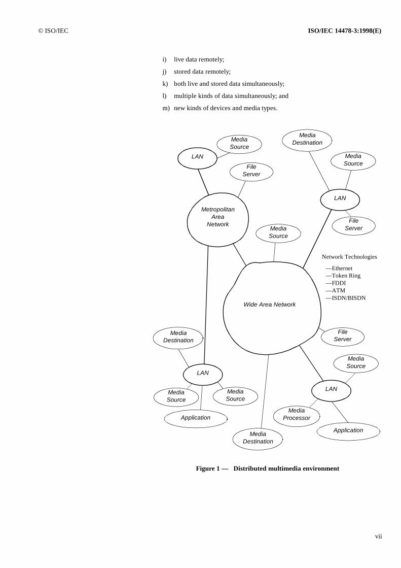
The primary goal of the MSS is to provide an infrastructure for building multimediacomputing platforms that support interactive multimedia applications dealing withsynchronized, time–based media in a heterogeneous distributed environment. Opera-tion in a distributed environment is important because of significant trends in the com-puter industry towards client/server and collaborative computing. Another significanttrend is towards multimedia enabled computing. The inevitable result will be an inter-section of these trends to produce a distributed multimedia environment with a topol-ogy similar to Figure 1.
The MSS is intended to address a broad range of application needs. It extends the mul-timedia capabilities of stand-alone computers to capabilities that are usable both local-ly and remotely. The Multimedia Systems Services gives applications the ability tohandle:
© ISO/IEC ISO/IEC 14478-3:1998(E)
vii
i) live data remotely;
j) stored data remotely;
k) both live and stored data simultaneously;
l) multiple kinds of data simultaneously; and
m) new kinds of devices and media types.
MetropolitanArea
Network
Wide Area Network
LAN
LAN
LAN
LAN
Application
Application
MediaSource
MediaDestination
FileServer
MediaProcessor
MediaSource
FileServer
MediaSource
FileServer
MediaSource
MediaDestination
MediaSource
MediaDestination
MediaSource
Network Technologies
— Ethernet— Token Ring— FDDI— ATM— ISDN/BISDN
Figure 1 — Distributed multimedia environment
ISO/IEC 14478-3:1998(E) © ISO/IEC
viii
To provide support for remote media device control and remote media access that de-rive from the above application scenarios, the Multimedia System Services uses twodistinct mechanisms. To support interaction with remote objects, the Multimedia Sys-tems Services depends upon an underlying object model and infrastructure, as de-scribed in ISO/IEC 14478–1 (PREMO). To support the media independent streamingof time critical data, the Multimedia Systems Services defines a Media Stream Con-trol.
The MSS does not address:
n) encryption and security;
o) intellectual property rights and accounting;
p) scripting;
q) user interfaces; or
r) sharing of data between applications.
1
INTERNATIONAL STANDARD © ISO/IEC ISO/IEC 14478-3:1998(E)
Information technology — Computer graphics and imageprocessing — Presentation Environment for Multimedia Objects(PREMO) —Part 3: Multimedia Systems Services
1 Scope
This part of ISO/IEC 14478 defines a standard set of multimedia system services that can be used by multimedia application de-velopers in a variety of computing environments. The focus is on enabling multimedia applications in a heterogeneous, distrib-uted computing environment. Throughout this part of ISO/IEC 14478, this component will also be referred to as “MultimediaSystems Services”, and abbreviated as MSS.
The Multimedia Systems Services constitutes a framework of “middleware” — system software components lying in the regionbetween the generic operating system and specific applications. As middleware, the Multimedia Systems Services marshals low-er–level system resources to the task of supporting multimedia processing, providing a set of common services which can be usedby multimedia application developers.
The Multimedia Systems Services encompasses the following characteristics:
a) provision of an abstract type for a media processing node, extensible through subtyping to support abstractions of realmedia processing hardware or software;
b) provision of an abstract type for the data flow path or the connection between media processing nodes, encapsulatinglow–level connection and transport semantics;
c) grouping of multiple processing nodes and connections into a single unit for purposes of resource reservation and streamcontrol;
d) provision of a media dataflow abstraction, with support for a variety of position, time and/or synchronization capabili-ties;
e) separation of the media format abstractions from the dataflow abstraction;
f) synchronous exceptions and asynchronous events;
g) application visible characterization of object capabilities;
h) registration of objects in a distributed environment by location and capabilities;
i) retrieval of objects in a distributed environment by location and constraints;
j) definition of a Media Stream Protocol to support media independent transport and synchronization.
The Multimedia Systems Services rely on the object model of ISO/IEC 14478-1 (Fundamentals of PREMO) and the object typesand non–object data types defined in ISO/IEC 14478-2 (PREMO Foundation Component).
ISO/IEC 14478-3:1998(E) © ISO/IEC
2
2 Normative references
The following standards contain provisions which, through reference in this text, constitute provisions of this part of ISO/IEC14478. At the time of publication, the editions indicated were valid. All standards are subject to revision, and parties to agree-ments based on this part of this international standard are encouraged to investigate the possibility of applying the most recenteditions of the standards indicated below. Members of IEC and ISO maintain registers of currently valid International Standards.
ISO/IEC 14478-1:1998, Information technology — Computer graphics and image processing — Presentation Environment forMultimedia Objects (PREMO) — Part 1: Fundamentals of PREMO.
ISO/IEC 14478-2:1998, Information technology — Computer graphics and image processing — Presentation Environment forMultimedia Objects (PREMO) — Part 2: Foundation Component.
ISO/IEC 14478-4:1998, Information technology — Computer graphics and image processing — Presentation Environment forMultimedia Objects (PREMO) — Part 4: Modelling, Rendering, and Interaction Component.
ISO/IEC 10918-1:1994, Information technology — Digital Compression and Coding of Continuous–Tone Still Images (JPEG).
ISO/IEC 11172:1992, Information technology — Coding of Moving Pictures and Associated Audio for Digital Storage Media atup to about 1.5Mbit/s (MPEG).
3 Definitions
3.1 PREMO Part 1 definitions
This part of ISO/IEC 14478 makes use of all terms defined in ISO/IEC 14478-1 (Fundamentals of PREMO).
3.2 PREMO Part 2 definitions
This part of ISO/IEC 14478 makes use of all terms defined in ISO/IEC 14478-2 (PREMO Foundation Component).
3.3 Additional definitions
For the purposes of this part of ISO/IEC 14478, the following definitions apply.
3.2.1 configuration objects: Collective name for format, quality of service descriptor, and media stream protocol objects.
3.2.2 jitter: Delay variance.
3.2.3 processing element (for virtual devices): Conceptual entity describing the internal behaviour of virtual device ob-jects.
3.2.4 virtual connection adapter: Conceptual entity describing the configuration process performed by a virtual connec-tion object.
3.2.5 unicast connection: One–to–one connection; an output port may be connected to one input port only, and an inputport may be connected to one output port only.
3.2.6 multicast connection: One–to–many connection; an output port may be connected to several input ports, and an in-put port may be connected to several output ports.
The following alphabetical list gives the subclause of each definition.
configuration objects 3.2.1jitter 3.2.2
© ISO/IEC ISO/IEC 14478-3:1998(E)
3
4 Symbols and abbreviations
ATM: Asynchronous Transfer Mode.
CATV: Cable TV
DMA: Direct Memory Access.
FSM: Finite State Machine.
IEC: International Electrotechnical Commission.
IS: International Standard.
ISO: International Organization for Standardization.
JPEG: Joint Picture Experts Group.
LAN: Local Area Network
MIDI: Musical Instrument Digital Interface
MPEG: Moving Picture Experts Group.
MSS: Multimedia Systems Services
PREMO: Presentation Environment for Multimedia Objects.
QoS: Quality of Service.
TCP: Transmission Control Protocol.
UDP: User Data Protocol.
RTP: Real–Time Protocol
5 Conformance
A conforming implementation of the PREMO Multimedia Systems Services shall comply with the general conformance rulesdefined in clause 5 of ISO/IEC 14478-1 and the component specification in clause 11 of This part of ISO/IEC 14478.
6 Overview of the Multimedia Systems Services
6.1 Introduction
This clause presents several comprehensive views of the Multimedia Systems Services, which, taken together, represent a broad,architectural summary. These views include:
a) an object interaction diagram, which characterizes the dynamic relationships among instantiated objects and to illustrateclient visible interfaces;
b) a subtyping diagram, which describes the subtyping hierarchy among MSS objects;
c) a short description of the life cycle of Multimedia Systems Services objects.
multicast connection 3.2.6processing element (for virtual devices) 3.2.3unicast connection 3.2.5virtual connection adapter 3.2.4
ISO/IEC 14478-3:1998(E) © ISO/IEC
4
A somewhat larger example of how the various MSS objects may be used is also given in Annex B.
6.2 Object framework
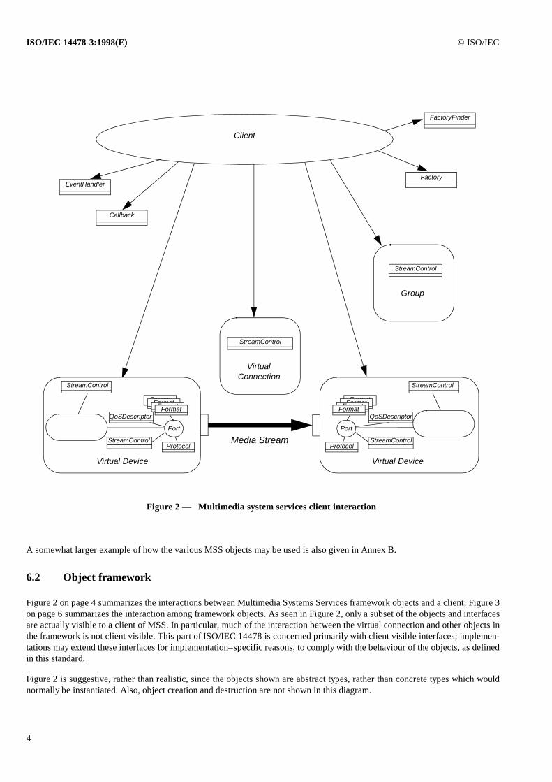
Figure 2 on page 4 summarizes the interactions between Multimedia Systems Services framework objects and a client; Figure 3on page 6 summarizes the interaction among framework objects. As seen in Figure 2, only a subset of the objects and interfacesare actually visible to a client of MSS. In particular, much of the interaction between the virtual connection and other objects inthe framework is not client visible. This part of ISO/IEC 14478 is concerned primarily with client visible interfaces; implemen-tations may extend these interfaces for implementation–specific reasons, to comply with the behaviour of the objects, as definedin this standard.
Figure 2 is suggestive, rather than realistic, since the objects shown are abstract types, rather than concrete types which wouldnormally be instantiated. Also, object creation and destruction are not shown in this diagram.
Protocol
FormatFormatFormatFormat
StreamControl
Port
StreamControl
Virtual Device
StreamControl
Virtual Connection
StreamControl
Group
Client
EventHandlerFactory
Media Stream
Figure 2 — Multimedia system services client interaction
FactoryFinder
Callback
QoSDescriptor
Protocol
FormatFormatFormatFormat
StreamControl
Port
StreamControl
Virtual Device
QoSDescriptor
© ISO/IEC ISO/IEC 14478-3:1998(E)
5
In Figure 2, the client is communicating with a small dataflow graph, comprised of two virtual devices and a virtual connection.A group object, which assists the client, is also shown. The client interacts with the objects indicated by the arrows. Each of theseobjects may be local or remote.
Each virtual device is a processing node in the dataflow graph. The nature of the processing (capture, encoding, filtering, etc.)varies according to the specific object (and is implemented by subtyping). Each virtual device contains a stream control objectand one or more format objects shown by the boxes in the shaded areas. Virtual connections and groups also have an associatedstream object and this association is represented similarly. These associations are referred to as inclusion. Although not explicitlyshown in the diagram, the client interacts directly with the included stream and format interfaces.
A stream control object provides the client with an interface to observe media stream position in various terms (as a function ofmedia transport, media samples, or logical time; see clause 8). Stream control objects also provide synchronization operations.Stream control objects do not perform the effective transfer of media data; they merely act as an entry for the clients to controlmedia flow.
In addition to a stream control, a virtual device also contains one or more ports, describing an input or output mechanism for thevirtual device. Ports are framework abstractions that do not have a client–visible interface. Virtual devices provide operations toselect a specific port, using an abstract non–object data type as an opaque handle.
Just as the stream control object allows a media stream control abstraction which is separable from media processing, the formatobject provides an abstraction of the details of media formatting which is separate from both processing and flow–control. Forexample, the details of a frame–dependent video encoding, like MPEG, would be represented by a subtype of format.
The virtual connection provides operations to create a connection between an output port of one virtual device and an input portof another, fully encapsulating low–level transport semantics. Virtual connections also provide support for multicast connections.An included stream object provides operations for controlling the dataflow on the virtual connection.
The group object, shown in Figure 2, provides assistance to the client to manage the dataflow graph of the two virtual devicesand the virtual connection. A group object provides a convenient mechanism for atomic resource allocation and specification ofend–to–end Quality of Service (QoS) values for the whole graph. The group object gives access to a stream object, through whichthe client can control dataflow for the encapsulated graph.
Multimedia Systems Services objects are instantiated by factories. A factory provides the client facilities to select among the var-ious objects that the factory is capable of creating. A client can also use the factory finder service to find a reference to a factorycapable of instantiating an object whose properties satisfy a list of constraints.
A client can register interest in receiving specific events produced by the various objects. This is done using the callback mech-anism and the event model as described in ISO/IEC 14478-2 (part 2 of PREMO).
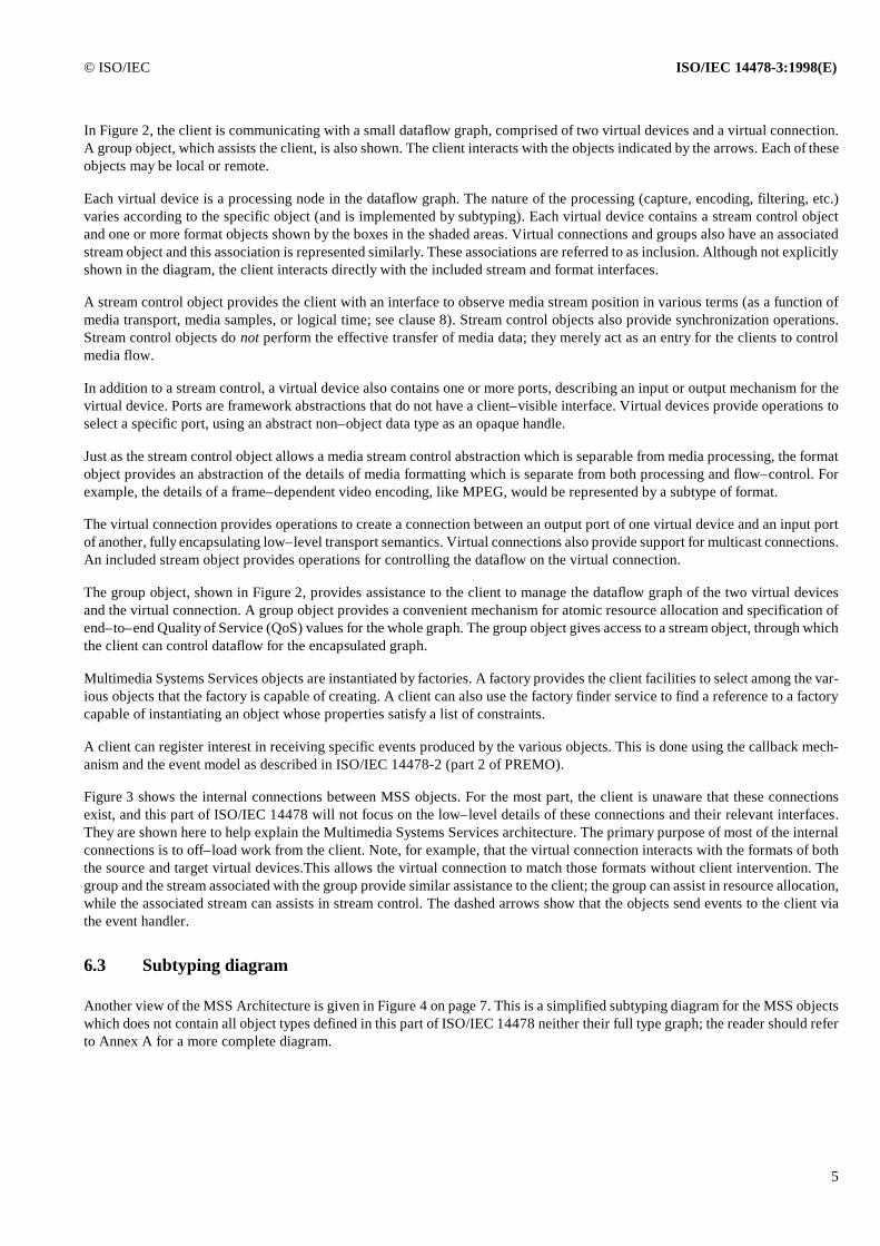
Figure 3 shows the internal connections between MSS objects. For the most part, the client is unaware that these connectionsexist, and this part of ISO/IEC 14478 will not focus on the low–level details of these connections and their relevant interfaces.They are shown here to help explain the Multimedia Systems Services architecture. The primary purpose of most of the internalconnections is to off–load work from the client. Note, for example, that the virtual connection interacts with the formats of boththe source and target virtual devices.This allows the virtual connection to match those formats without client intervention. Thegroup and the stream associated with the group provide similar assistance to the client; the group can assist in resource allocation,while the associated stream can assists in stream control. The dashed arrows show that the objects send events to the client viathe event handler.
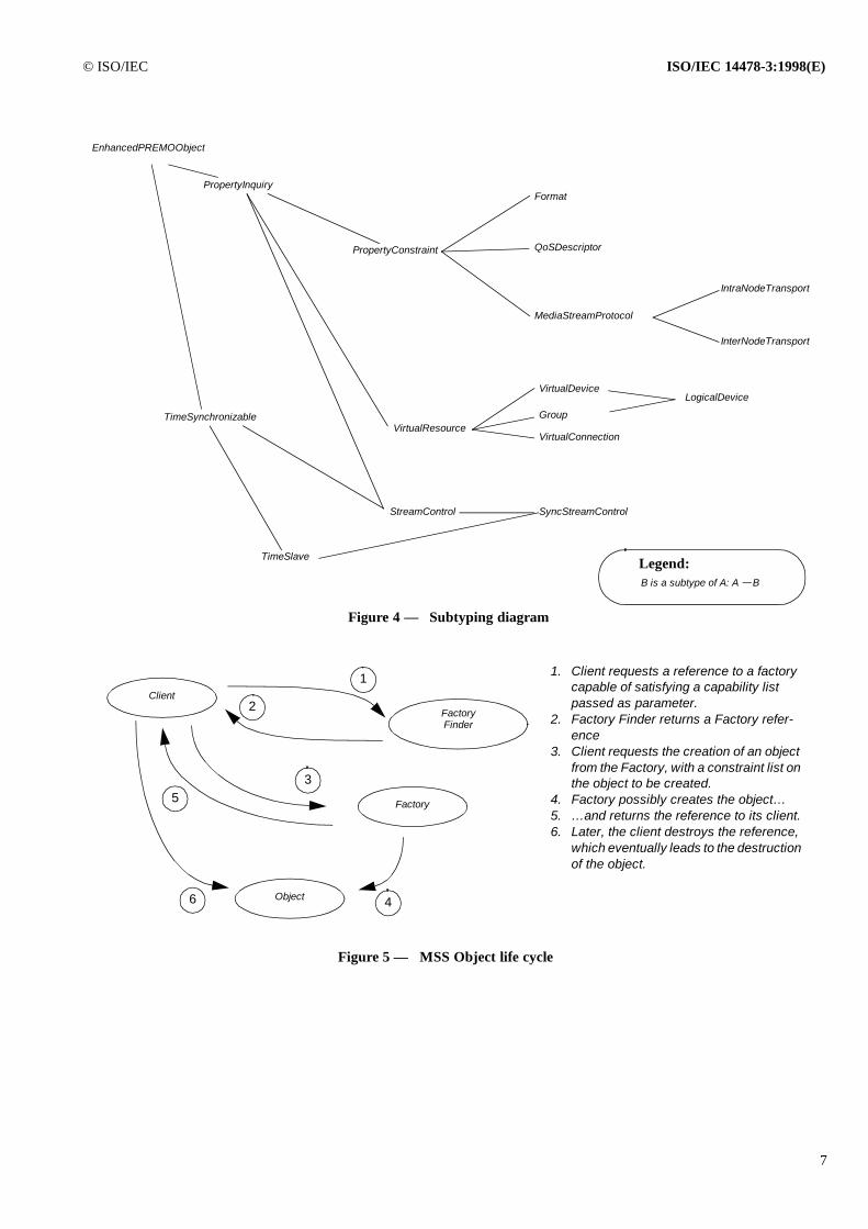
6.3 Subtyping diagram
Another view of the MSS Architecture is given in Figure 4 on page 7. This is a simplified subtyping diagram for the MSS objectswhich does not contain all object types defined in this part of ISO/IEC 14478 neither their full type graph; the reader should referto Annex A for a more complete diagram.

ISO/IEC 14478-3:1998(E) © ISO/IEC
6
The types in the diagram will be discussed in detail elsewhere in this part of ISO/IEC 14478. For the time being the only importantcharacteristic to note is that all types defined in MSS are subtypes of EnhancedPREMOObject (see ISO/IEC 14478-2), therebyinheriting all features described in the Foundation Component of PREMO. Also, all objects are subtypes of PropertyInquiry,which is further described in 8.1.2 of ISO/IEC 14478-2 (part 2 of PREMO).
6.4 MSS object life cycle
Figure 5 on page 7 gives a schematic view of the life cycle of an MSS object and its reference. Beyond the basic life cycle ofPREMO objects, as described in ISO/IEC 14478-1, all MSS objects rely on the concepts of factories and factory finders definedin the extended profile of ISO/IEC 14478-2 (see 8.2.1 of ISO/IEC 14478-2 for a detailed description of these facilities), whichencapsulate normal object and object reference creation. The client has the ability to create objects through these factories byspecifying constraints on the capabilities of the object to be created (e.g., media formats it can process, quality of service it canprovide, etc.). The client receives from the factory an object reference to an object obeying these requirements. This object ref-erence goes then through the life cycle as described in 8.11 of ISO/IEC 14478-1.
Figure 3 — Multimedia system services internal interfaces
Protocol
FormatFormatFormatFormat
StreamControl
Port
StreamControl
Virtual Device
StreamControl
Group
Client
EventHandler
Media Stream
Callback
Protocol
FormatFormatFormatFormat
StreamControl
Port
StreamControl
Virtual Device
StreamControl
Virtual Connection
QoSDescriptor QoSDescriptor
© ISO/IEC ISO/IEC 14478-3:1998(E)
7
MediaStreamProtocol
B is a subtype of A: A B
Format
SyncStreamControlStreamControl
VirtualResource
VirtualDevice
PropertyInquiry
PropertyConstraint
EnhancedPREMOObject
Figure 4 — Subtyping diagram
Legend:
QoSDescriptor
IntraNodeTransport
InterNodeTransport
VirtualConnection
Group
LogicalDevice
TimeSynchronizable
TimeSlave
Figure 5 — MSS Object life cycle
Client
FactoryFinder
Factory
Object
1. Client requests a reference to a factory capable of satisfying a capability list passed as parameter.
2. Factory Finder returns a Factory refer-ence
3. Client requests the creation of an object from the Factory, with a constraint list on the object to be created.
4. Factory possibly creates the object…5. … and returns the reference to its client.6. Later, the client destroys the reference,
which eventually leads to the destruction of the object.
1
2
3
46
5
ISO/IEC 14478-3:1998(E) © ISO/IEC
8
7 Configuration objects
7.1 Introduction
The various MSS object types, categorized as configuration objects, are used as information depositories for other objects. Con-figuration objects do not provide complicated behaviour to their clients; instead, their role is to act as placeholders for the neces-sary parameters which allow other objects to function properly. Configuration objects are not used in isolation; they are alwaysassociated with an object of type VirtualResource object (see 9.1) whose behaviour they affect.
All configuration objects are subtypes of PropertyConstraint objects (see 8.1.3 of ISO/IEC 14478-2), and the various parametersthey provide to other objects are stored and manipulated through the property constraining mechanism which characterize thePropertyConstraint objects. Typically, configurable MSS objects (e.g., resource objects, see clause 9) contain several instancesof configuration objects, whose references can be accessed by the external clients; through the constrain, select, etc., operationsthese clients can then set the required values for the configuration objects.
Usage of configuration objects is the basic mechanism for configurability in PREMO. Clients may inquire the key–value pairsassociated with these objects and, through the property constrain and selection mechanism (see 8.1.3 of ISO/IEC 14478-2) mayrestrict these values. The algorithms for constraining the possible values (within the limits defined by the capabilities and thenative property values of the configuration objects) depend on the client and is not standardized by PREMO. These algorithmsmay take into consideration the full set of configuration objects associated to the same VirtualResource instance. Note that furthersubtypes of configuration objects may be defined with an inherent constraint algorithm, which is made available through the se-lect operation of the configuration object (see again 8.1.3 of ISO/IEC 14478-2).
The MSS has three categories of configuration objects, described below:
a) Format objects;
b) Transport and Media Stream Protocol objects;
c) Quality of Service objects.
7.2 Format objects
The role of the Format object type is to represent the details of the media format (that is, the organization of the bitstream) at aparticular port of a device (see clause 9). The characteristics of a specific media format are described in form of object propertiesdefined on the corresponding Format object.
NOTE — For example, the organization of data in an MPEG data stream is different from the organization of data in an a-law audio stream.The Format object allows the client to specify as little or as much about a particular encoding as it wants. When a connection is made to a port,the virtual connection interacts with the Format object to negotiate the details of the bitstream to be passed between virtual device ports.
The Multimedia Systems Services do not define specific format objects; instead, it defines a general architecture which makessuch a specification possible. However, the (informative) Annex C of this part does describe a hierarchy of format and deviceobjects which provide a good example of how this general architecture should be used.
7.3 Transport and Media Stream Protocol objects
When a virtual connection determines that two virtual devices cannot be directly connected (often because they are on differentmachines), it creates a virtual connection adapter to transport media data between them (see 9.3). The virtual devices may residein different implementations of the Multimedia Systems Services, so the virtual connection adapter must share a common proto-col in order to interoperate.
The purpose of the Transport and Media Stream Protocol (MSP) objects is to provide information on how media data is conveyedamong processing nodes. It is not the role of MSS to give a detailed specification of the various possible communication proto-cols, only references to existing protocol specifications are made here. In MSS, MSP objects have two subtypes:
© ISO/IEC ISO/IEC 14478-3:1998(E)
9
a) IntraNodeTransport, which refers to communication among nodes taking place through shared memory (e.g., two nodesprocessing in the same address space of a workstation using, e.g., DMA)
b) InterNodeTransport, which refers to communication among nodes taking place over a network, or through some inter–process communication means. The various protocol names which can characterize these protocols include IPC, UDP, RTP,ATM, or NETBIOS.
The virtual connection determines the format of the media data, including its bit–level representation, by negotiation with therelevant Format objects (see 7.2) and perhaps with client intervention. Similarly, the client will conduct negotiations on the detailof the transfer protocols, using the MSP objects. From the point of view of MSP objects the media data is an opaque entity. Nei-ther the virtual connection adapter nor the underlying network transports know how to extract information from the media data.
To allow for future revisions, the MSP properties include a protocol version number.
7.4 Quality of Service Descriptor objects
In order for a virtual resource to be useful, it must obtain the physical resources required for it to do its job. Resources includeboth system resources that are typically not multimedia specific, such as those provided by the CPU, memory, and network sub-systems, as well as specialized multimedia resources such as audio and video devices.
Because the quality of service that can be provided by many resources varies considerably, the client must also specify the desiredquality of service when requesting a resource; this is done by setting the properties of a special information depository object inMSS, called the QoSDescriptor object.
Though quality of service can take on many meanings, many of them media and device specific, the Multimedia Systems Servicesdefines a core set of QoSDescriptor properties that can be used by a client to specify the quality of service of interest. The coreQoSDescriptor characteristics defined by the Multimedia Systems Services are:
a) guaranteed level (key “GuaranteedLevelK”): provides options for “Guaranteed” service, “BestEffort” service or“NoGuarantee” service;
b) reliable (key “ReliableK”): the delivery of data is reliable or not;
c) delay bounds (key “DelayBoundsK”): the minimum and maximum delay;
d) jitter bounds (key “JitterBoundsK”): the minimum and maximum jitter (delay variance);
e) bandwidth bounds (key “BandwidthBoundsK”): the minimum and maximum bandwidth.
The client specifies the desired QoSDescriptor properties by accessing the quality of service information from a VirtualResourceobject, and manipulating the property values with the property management operations.
The guaranteed level property is an indication of the performance required of the virtual connection (see 9.3 for a more detailedpresentation of virtual connections). A “Guaranteed” connection will reserve resources appropriate to handle worst–case needsfor the media transfer in order to make sure that the data always arrives and is on time. A “BestEffort” connection will providethe best possible performance while using optimistic amounts of resources. This may produce situations where the data occasion-ally arrives late. “NoGuarantee” uses the minimum amount of resources for the connection and do as well as possible.
The reliability property indicates whether the application is willing to suffer data loss.
Delay is the amount of time between the transmission of the data and the receipt of the data. Different applications will havedifferent requirements. For instance, an audio conference would be unwilling to live with a 2 second delay, whereas a non-inter-active video playback application might find it acceptable.
Bandwidth is the amount of data per unit time that the connection will be required to support or, in the case of an input port, toexpect. For example, a video conference might require 384 Kbits/second while an MPEG stream might require 1.5 Mbits/second.By defining the range of the bandwidth required, the connection will understand the maximum burst that it must handle.
ISO/IEC 14478-3:1998(E) © ISO/IEC
10
Jitter is the amount of delay variance. For example, an ISDN channel that presents a “slot” of data every 125 microseconds hasa jitter of 0, since there is no variance in the arrival time of the data. If an application requests a jitter close to 0, then the connectionwill try to find an isochronous network connection between the two virtual devices.
Subtypes of QoSDescriptor objects may extend the QoSDescriptor management with additional characteristics.
8 Stream Controls
The StreamControl type, and its subtypes, provide a single point of focus for all inquiry and control of media stream progress ina media type independent way. StreamControl objects are never created in isolation; they are included objects of VirtualResourceobjects whose role is to monitor and control stream progress for the overall resource. Various virtual resource objects need sub-types of the stream objects defined in MSS to cope with the various media–dependent characteristics, e.g., details of media pres-entation. The MSS gives a formal specification of two objects only, namely the StreamControl and the SyncStreamControl objecttypes; semantic details of the various subtypes are beyond the scope of MSS and are not considered in This part of ISO/IEC14478.
NOTE — Further PREMO components may define subtypes of the StreamControl and SyncStreamControl objects.
The StreamControl type provides operations to observe and control media position. A complication is that different objects re-quire different concepts of position:
a) Transport aware object: the object might understand transport packets, but not understand the structure of the mediastream. The object can only report the stream address, that is the byte count since the stream began to flow.
b) Media Stream aware object: the object might understand media samples, but not how media samples translate intostream time. The object can report the stream sample count.
c) Time aware object: the object understands how to extract stream time from the media stream. The object can report thestream time.
To answer to these concerns, the StreamControl object is defined in MSS to be a subtype TimeSynchronizable, described in detailin 7.9 of ISO/IEC 14478-2. Inheriting the behaviour of these objects, clients of StreamControl objects have the ability to accessand control the stream position in terms of:
d) Media stream data: The internal progression space of the object (i.e., index of a sample).
e) Relative time: The time elapsed from an origin, settable by the client. One can achieve effects like “pause at 100ms fromorigin”.
Synchronization elements can be put at various points of the stream, using either media stream data or relative time. This meansthat a StreamControl object will send events when these points are crossed. Such synchronization elements can be set periodical-ly, i.e., one can achieve effects like “send an event at each 100ms”.
Stream control objects do not perform the transfer of media data; they merely act as an entry for the clients to control media flow.Conceptually, media data transfer is done by the processing element of the VirtualDevice object and, hence, is opaque to the cli-ent.
The StreamControl object does not specify further the internal progression space of TimeSynchronizable (which is a generictype), i.e., whether the internal progression is done in the integer, real, or time domain. Specific VirtualDevice objects have toactualize the StreamControl objects they use by making this decision.
8.1 StreamControl objects
The StreamControl object adds a finer media control to its supertype TimeSynchronizable. This finer control is achieved throughthe refinement of the finite state machine governing the behaviour of TimeSynchronizable.
© ISO/IEC ISO/IEC 14478-3:1998(E)
11
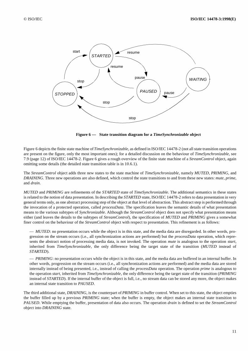
Figure 6 depicts the finite state machine of TimeSynchronizable, as defined in ISO/IEC 14478-2 (not all state transition operationsare present on the figure, only the most important ones); for a detailed discussion on the behaviour of TimeSynchronizable, see7.9 (page 12) of ISO/IEC 14478-2. Figure 6 gives a rough overview of the finite state machine of a StreamControl object, againomitting some details (the detailed state transition table is in 10.6.1).
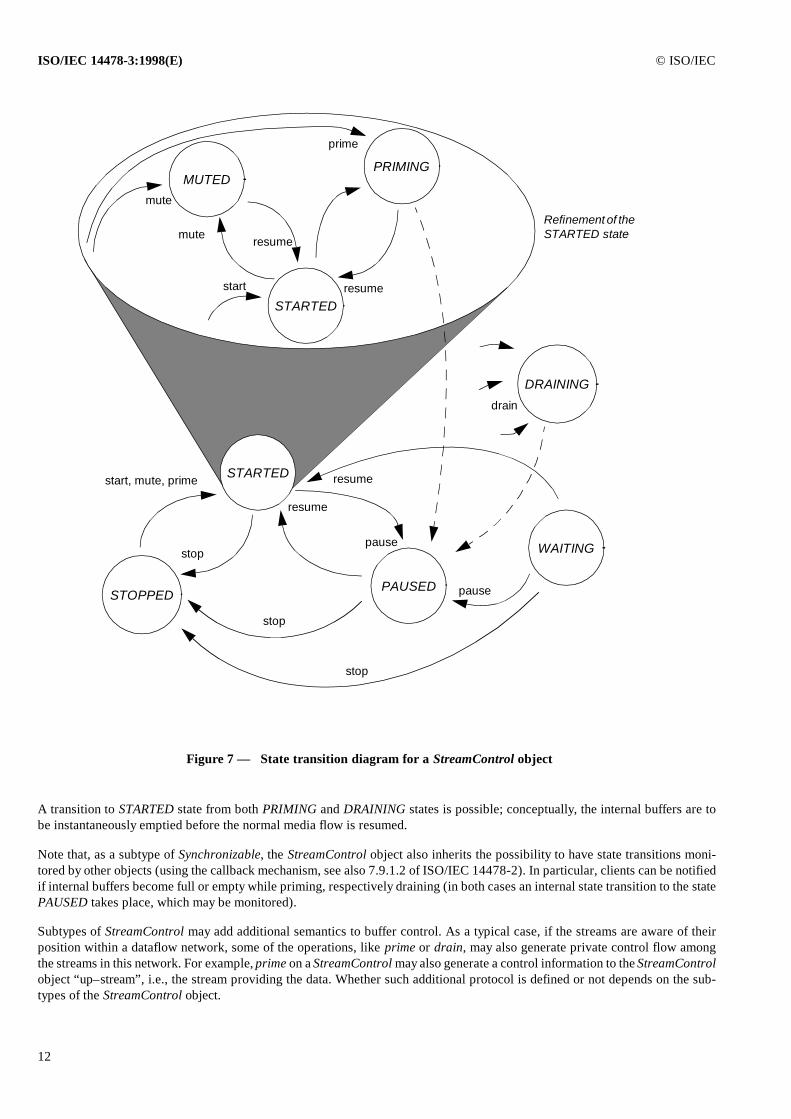
The StreamControl object adds three new states to the state machine of TimeSynchronizable, namely MUTED, PRIMING, andDRAINING. Three new operations are also defined, which control the state transitions to and from these new states: mute, prime,and drain.
MUTED and PRIMING are refinements of the STARTED state of TimeSynchronizable. The additional semantics in these statesis related to the notion of data presentation. In describing the STARTED state, ISO/IEC 14478-2 refers to data presentation in verygeneral terms only, as one abstract processing step of the object at that level of abstraction. This abstract step is performed throughthe invocation of a protected operation, called processData. The specification leaves the semantic details of what presentationmeans to the various subtypes of Synchronizable. Although the StreamControl object does not specify what presentation meanseither (and leaves the details to the subtypes of StreamControl), the specification of MUTED and PRIMING gives a somewhatfiner control on the behaviour of the StreamControl object with respect to presentation. This refinement is as follows:
— MUTED: no presentation occurs while the object is in this state, and the media data are disregarded. In other words, pro-gression on the stream occurs (i.e., all synchronization actions are performed) but the processData operation, which repre-sents the abstract notion of processing media data, is not invoked. The operation mute is analogous to the operation start,inherited from TimeSynchronizable, the only difference being the target state of the transition (MUTED instead ofSTARTED).
— PRIMING: no presentation occurs while the object is in this state, and the media data are buffered in an internal buffer. Inother words, progression on the stream occurs (i.e., all synchronization actions are performed) and the media data are storedinternally instead of being presented, i.e., instead of calling the processData operation. The operation prime is analogous tothe operation start, inherited from TimeSynchronizable, the only difference being the target state of the transition (PRIMINGinstead of STARTED). If the internal buffer of the object is full, i.e., no stream data can be stored any more, the object makesan internal state transition to PAUSED.
The third additional state, DRAINING, is the counterpart of PRIMING in buffer control. When set to this state, the object emptiesthe buffer filled up by a previous PRIMING state; when the buffer is empty, the object makes an internal state transition toPAUSED. While emptying the buffer, presentation of data also occurs. The operation drain is defined to set the StreamControlobject into DRAINING state.
STOPPED
STARTED
PAUSED
start
pausestop
resume
stop
WAITING
resume
stop
pause
Figure 6 — State transition diagram for a TimeSynchronizable object
ISO/IEC 14478-3:1998(E) © ISO/IEC
12
A transition to STARTED state from both PRIMING and DRAINING states is possible; conceptually, the internal buffers are tobe instantaneously emptied before the normal media flow is resumed.
Note that, as a subtype of Synchronizable, the StreamControl object also inherits the possibility to have state transitions moni-tored by other objects (using the callback mechanism, see also 7.9.1.2 of ISO/IEC 14478-2). In particular, clients can be notifiedif internal buffers become full or empty while priming, respectively draining (in both cases an internal state transition to the statePAUSED takes place, which may be monitored).
Subtypes of StreamControl may add additional semantics to buffer control. As a typical case, if the streams are aware of theirposition within a dataflow network, some of the operations, like prime or drain, may also generate private control flow amongthe streams in this network. For example, prime on a StreamControl may also generate a control information to the StreamControlobject “up–stream”, i.e., the stream providing the data. Whether such additional protocol is defined or not depends on the sub-types of the StreamControl object.
Figure 7 — State transition diagram for a StreamControl object
STOPPEDPAUSED
start, mute, prime
pausestop
resume
stop
WAITING
resume
stop
pause
MUTED
STARTED
PRIMING
prime
mute
DRAINING
drain
Refinement of the STARTED state
STARTED
resumestart
mute resume
© ISO/IEC ISO/IEC 14478-3:1998(E)
13
StreamControl objects are also subtype of PropertyInquiry. This means that subtypes of StreamControl objects may also takepart in complex negotiations based on properties, as described in 8.1 of ISO/IEC 14478-2 (part 2 of PREMO).
8.2 SyncStreamControl objects
The SyncStreamControl type is designed to permit the synchronization of multiple media streams. The client specifies a secondStreamControl object to provide a master position reference to the SyncStreamControl. This functionality is achieved by inher-iting the behaviour of the TimeSlave objects, defined in 7.9.3 of ISO/IEC 14478-2. SyncStreamControl is defined as a (multiple)subtype of both the StreamControl and the TimeSlave object types, thereby refining the finite state machine of a TimeSlave objectthe same way as StreamControl objects refine the behaviour of TimeSynchronizable objects.
NOTE — The SyncStreamControl type provides the client with a variety of options with respect to setting up how synchronization is to beachieved. For example, a video display device can be synchronized with an audio display device by setting up the appropriate relationshipbetween their associated StreamControl objects. Assuming the video device supports a SyncStreamControl type, the audio device'sStreamControl object can be made the master of the video device's SyncStreamControl object.
In another situation, the client may want to synchronize two displays to a common time reference. In this case, both displays would have tosupport the SyncStreamControl type. The client would make the StreamControl object associated with the time reference the master of theStreamControl objects associated with both the display objects.
9 Devices, Resources
9.1 Virtual Resources
A virtual resource is an abstraction of a physical resource that provides the client developer a consistent programming model,independent of the details of specific implementations. The notion of a virtual resource makes applications more portable acrossa variety of systems, while at the same time making the transparent sharing of physical resources possible.
The Multimedia Systems Services defines four basic subtypes of virtual resources:
a) virtual devices, which abstract media processors;
b) virtual connections, which abstract connections between virtual devices;
c) groups, which provide a convenient way to interact with a collection of virtual devices and connections;
d) logical devices, which provide a possibility to build a hierarchy of virtual devices.
The MSS defines a VirtualResource object type, which serves as a common, abstract supertype for these three categories. Thisclause describes this object type in more details.
9.1.1 Configuration objects on virtual resources
The externally visible aspects of virtual resources are described primarily in terms of a set of associated configuration objects(although subtypes of VirtualResource add additional operations which modify the behaviour of virtual resources, too). Theseconfiguration objects are created and contained by the VirtualResource object instance, i.e., these objects are not created by anexternal client. Also, the object references of these configuration objects are not directly visible to the client; instead, the virtualdevice object publishes (through a property with key “ConfigurationNamesK”) information on the semantic name (which is astring) and the type of the various configuration objects it includes. Although it is possible, through a special resolve operation,to get access to the real object reference of these configuration objects, most of the operations defined on the VirtualResourcetype and its subtypes are defined in terms of the semantic names of the configuration objects, rather than object references. Thismechanism provides an extra protection against configuration errors and makes implementation of virtual resource objects moreeffective. Also, most of the application should be able to be properly configured with the configuration objects (and the setting
ISO/IEC 14478-3:1998(E) © ISO/IEC
14
of their properties) as provided by default by the virtual resource object. On the other hand, through the object reference returnedby the resolve operation, clients can also implement more complicated configuration procedures, using all the facilities of prop-erty control described in 8.1 of ISO/IEC 14478-2.
The static properties of configuration objects (see clause 7) are bound by the VirtualResource object when acquiring resources(through the VirtualResource.acquireResource operation) by internally invoking the bind operation on all these configuration ob-jects. Static properties are unbound when the resources of the VirtualResource object are released.
Virtual resources can also act as event sources; an attribute of type RefEventHandler is associated to the object, hence the clientcan set the event handler for the events raised by a specific virtual resource.
9.1.2 Stream control
Typically, virtual resources are involved in the generation, consumption, or transport of media data. The flow of media datathrough a device or across a connection can be thought of as a stream. In order to monitor or control the progress of the (possiblyabstract) stream, an overall StreamControl object (see clause 8) is associated to a VirtualResource object. This stream controlobject is created and contained by the VirtualResource object instance, i.e., this object is not created by an external client.
A client can get a reference to the StreamControl object associated with a VirtualResource by accessing the stream attribute ofthe object. Once the client has obtained a reference to a StreamControl object, it may be able to cast its reference to one of themore capable StreamControl subtypes.
It should be noted that not all virtual resources have a notion of stream control. In these cases, the resource's stream attribute mayhave a value of NULLObject (this may occur, for example, when the VirtualResource in question is abstracting an external devicesuch as a CATV tuner, which would have no notion of stream control).
9.1.3 Resource management
When a virtual resource is requested to acquire resources, one or more resource managers, which are responsible for managingthe access to physical resources necessary to realize the virtual resource, get involved in the resource allocation process. Depend-ing on the Multimedia Systems Services implementation, there may be one resource manager per managed resource, or there maybe one resource manager per group of resources or per system. From the point of view of PREMO, these resource managers arepurely conceptual entities, and this part of ISO/IEC 14478 does not contain a detailed specification of these. However, this ab-straction is useful in describing the externally visible behaviour of virtual resource objects.
When the VirtualResource.acquireResource operation is executed, the VirtualResource object communicates with the appropri-ate resource manager(s) to request allocation to resources. The resource manager(s) which are contacted by the virtual resourceare dependent on the type of virtual resource and the Multimedia Systems Services implementation; typically, virtual resourcesare created with the information necessary to contact the appropriate resource manager(s) at resource allocation time. Some re-source managers may have a generic interface for specifying resources, essentially providing a direct reflection of the acquireRe-source operation. Other resource managers may provide a more specific interface appropriate to the resource being managed;virtual resources requesting the use of such resources would by their nature understand the necessary vocabulary for making re-source requests.
The resource manager(s) may allow multiple virtual resources to share a given physical resource, so long as the desired config-uration of the virtual resource, e.g., quality of service, can be met. See 9.1.4 below for details on quality of service management.
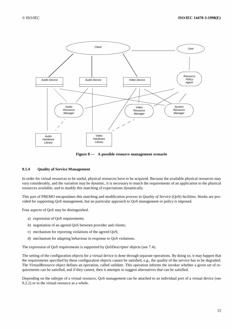
NOTE — Figure 8 on page 15 depicts a possible resource management configuration. As presented on the figure, resource managers maywork in conjunction with a resource policy agent, whose task is to permit the user to get involved with the resource allocation decisions, muchin the same way as a window manager allows the user to make window size and placement decisions in a window system. When a resourcemanager has had a resource policy agent registered with it, resource management requests are redirected to the resource policy agent. Theresource policy agent may get the user involved in the process, and it then resubmits a potentially modified request on the client's behalf backto the resource manager. This mechanism is similar in style to that used in the X Window System.
© ISO/IEC ISO/IEC 14478-3:1998(E)
15
9.1.4 Quality of Service Management
In order for virtual resources to be useful, physical resources have to be acquired. Because the available physical resources mayvary considerably, and the variation may be dynamic, it is necessary to match the requirements of an application to the physicalresources available, and to modify this matching of expectations dynamically.
This part of PREMO encapsulates this matching and modification process in Quality of Service (QoS) facilities. Hooks are pro-vided for supporting QoS management, but no particular approach to QoS management or policy is imposed.
Four aspects of QoS may be distinguished.
a) expression of QoS requirements;
b) negotiation of an agreed QoS between provider and clients;
c) mechanism for reporting violations of the agreed QoS;
d) mechanism for adapting behaviour in response to QoS violations.
The expression of QoS requirements is supported by QoSDescriptor objects (see 7.4).
The setting of the configuration objects for a virtual device is done through separate operations. By doing so, it may happen thatthe requirements specified by these configuration objects cannot be satisfied, e.g., the quality of the service has to be degraded.The VirtualResource object defines an operation, called validate. This operation informs the invoker whether a given set of re-quirements can be satisfied, and if they cannot, then it attempts to suggest alternatives that can be satisfied.
Depending on the subtype of a virtual resource, QoS management can be attached to an individual port of a virtual device (see9.2.2) or to the virtual resource as a whole.
Figure 8 — A possible resource management scenario
Audio Device Video DeviceAudio DeviceResource
Policy Agent
AudioResourceManager
VideoResourceManager
SystemResourceManager
AudioHardware
Library
VideoHardware
Library
Client User
ISO/IEC 14478-3:1998(E) © ISO/IEC
16
Notification of QoS violations is supported by a callback mechanism, using PREMO events; if a VirtualResource identifies aQoS violation, it will send an event to a registered Callback object. This could be used to invoke a QoS manager, though QoSmanagers are not standardized by this part of PREMO. The format of QoS violation events is as follows:
— the name of the event is “QoSViolation”;
— the event data should contain the key–value pairs whose requirement have been violated;
— if the QoS management is attached to a port of a virtual device (see 9.2.2), the key “PortID”, with a value identifying theport, should be added to the event data.
Specific subtypes of VirtualResource objects may add additional event data to this event.
The behaviour of a resource can be modified in response to a QoS violation by changing the QoSDescriptor and reinvoking thenegotiation process. This part of PREMO does not standardize specific mechanisms and object types for doing this.
NOTE — An example for a possible policy is as follows. When a resource manager detects that it cannot satisfy the quality of servicerequirements of its virtual resource clients, usually in response to a new request to share a physical resource, it may have to pre–empt arunning virtual resource. When this happens, an event is sent to the virtual resource notifying it that it has lost access to the physical resource;the virtual resource, in turn, generates an event with the name “Resource Lost”, notifying an event client that it has been pre–empted. At alater time, if the resource manager detects that it can meet the needs of a pre–empted virtual resource, it may send an event to the virtualresource notifying it that it has gained access to the physical resource; the virtual resource, in turn, generates an event with the name“Resource Acquired”, notifying the client that it has regained use of its resources.
9.2 Virtual Devices
A VirtualDevice is a subtype of VirtualResource that abstracts interaction processing or presentation capabilities. These devicesmay be hardware devices, such as capture and display cards, complex media renderers (see, e.g., the subtypes of VirtualDevicedefined in ISO/IEC 14478-4, part 4 of PREMO), or they may be software “devices” such as compressor/decompressors. A virtualdevice may represent a resource internal to a system, such as an audio capture device, or it may represent a resource external toa system, such as a CATV tuner.
The virtual device abstraction is designed to provide a common way for clients to use a wide variety of capabilities in many kindsof operating environments. Some of the key considerations that influenced the VirtualDevice interface design are:
a) Resource management: Almost all devices require some system resources, such as CPU and memory, to perform theirfunction. Some require the use of specialized hardware, access to which needs to be managed. In order to permit sharing ofresources among several simultaneously active clients, multiple virtual devices may use a single physical resource at thesame time. However, the client is insulated from the details of resource sharing and can largely behave as if it has exclusiveaccess to the resource.
b) Stream position control: Devices typically operate on a stream of media data. The client interacts with a virtual device'sStreamControl objects (see clause 8) to determine stream position and to control various aspects of stream progress. Thedegree to which a device can report or control the position in the data stream is determined by the subtype of StreamControltype with which it can be associated.
c) Device abstraction: Physical devices can vary substantially from manufacturer to manufacturer. Not only are the set offunctions often different, but the way in which they are combined and accessed is commonly different. Yet an applicationwriter does not want to write specialized code to operate on each manufacturer's device: a set of common abstractions isneeded.
d) Media format abstraction: The format of media data processed by devices also varies considerably. There are many dif-ferent kinds of audio encodings, and even more video encodings. Some encodings are quite complex, requiring a plethora ofdetails to be properly negotiated to interpret the data correctly. The abstraction of media data may also encompass for com-plex, time–based descriptions of multimedia presentation data, see, e.g., ISO/IEC 14478-4, part 4 of PREMO. The client istypically interested in few (if any) of these details, whereas the Multimedia Systems Services framework must necessarily beconcerned with all of them.
© ISO/IEC ISO/IEC 14478-3:1998(E)
17
e) Virtual devices can also be used to allow modelling, rendering, and interaction to be uniformly integrated into a networkof objects for managing the production and utilization of multimedia data. See, e.g., ISO/IEC 14478-4, part 4 of PREMO forfurther examples of such devices.
The construction of the Multimedia Systems Services VirtualDevice type has been designed to address these considerations whileproviding an expressive, flexible framework into which a large spectrum of media devices may be cast.
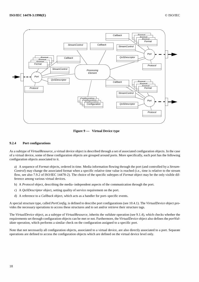
The following subclauses describes the roles of the various components that make up a virtual device. (These components arealso depicted on Figure 9; note that only the shaded boxes, and their client–visible interfaces, are standardized by PREMO) Allof these elements work together to provide the client a useful abstraction of a physical device. Separating the various functionsrelated to a virtual device into distinct types permits a wide variety of physical devices to be represented cleanly.
9.2.1 Processing element
The processing element is an abstract representation of the part of a virtual device that performs the operations which are abstract-ed by a particular VirtualDevice type. It is the functionality of this virtual device component that determines a particular virtualdevice's position in the VirtualDevice type hierarchy. From the point of view of PREMO, processing elements are purely con-ceptual entities and clients never directly interact with them. A particular virtual device may have a complex internal structure.Consequently, this part of ISO/IEC 14478 does not contain a detailed specification of their interfaces. However, this abstractionis useful in describing the externally visible behaviour of virtual device objects.
9.2.2 Ports
The processing element gets its input data from and sends its output data to ports. For example, an MPEG decompressor couldbe defined as having a single input port and two output ports (one audio and one video). From a client's perspective, ports aredistinguished by an abstract non–object data type, identifying individual ports. The port itself is not normally accessed by theclient. It exists to perform data movement operations needed the Multimedia Systems Services framework.
9.2.3 Streams
The client can focus all inquiry and control methods concerning data stream position at the StreamControl interface. The clientcan obtain a reference to the virtual device's overall StreamControl object by through the (inherited) stream attribute.
In addition to the overall StreamControl object, StreamControl objects may be available to interact with the stream position atindividual ports. The VirtualDevice type provides a getPortPortConfig operation that can be used to get references to the Stream-Control object associated with individual ports. The StreamControl objects associated with individual ports are subtypes of theoverall StreamControl object associated with the virtual device itself.
The immediate type of the StreamControl objects associated to the port(s) of the virtual device shall be a subtype of the device’soverall StreamControl object. Virtual device may differ from one another in the choice of StreamControl object which they as-sociate either on an overall level and/or on a port–by–port basis.
NOTE — For example, a virtual device for an MPEG decoder may declare a subtype of StreamControl, say, MStreamControl, which is theimmediate type of its overall StreamControl. This requirement says that all StreamControl objects, exported by the MPEG decoder, shall be asubtype of MStreamControl.
A particular virtual device may decide not to associate a StreamControl object to one of its ports, i.e., the object reference refersto NULLObject; the same is valid for the device’s overall StreamControl object. Also, the same reference for a StreamControlobject may be returned for multiple ports and for the overall StreamControl.
NOTE — For example, a virtual device, simply interpreting an audio file and sending the audio data on its output port, might be realized witha single output port defined for the device. In this case, the overall StreamControl and the StreamControl associated to that single output portmight be the same, i.e., the object references would refer to the same object instance.
ISO/IEC 14478-3:1998(E) © ISO/IEC
18
9.2.4 Port configurations
As a subtype of VirtualResource, a virtual device object is described through a set of associated configuration objects. In the caseof a virtual device, some of these configuration objects are grouped around ports. More specifically, each port has the followingconfiguration objects associated to it.
a) A sequence of Format objects, ordered in time. Media information flowing through the port (and controlled by a Stream-Control) may change the associated format when a specific relative time value is reached (i.e., time is relative to the streamflow, see also 7.9.2 of ISO/IEC 14478-2). The choice of the specific subtypes of Format object may be the only visible dif-ference among various virtual devices.
b) A Protocol object, describing the media–independent aspects of the communication through the port.
c) A QoSDescriptor object, setting quality of service requirement on the port.
d) A reference to a Callback object, which acts as a handler for port–specific events.
A special structure type, called PortConfig, is defined to describe port configurations (see 10.4.1). The VirtualDevice object pro-vides the necessary operations to access these structures and to set and/or retrieve their structure tags.
The VirtualDevice object, as a subtype of VirtualResource, inherits the validate operation (see 9.1.4), which checks whether therequirements set through configuration objects can be met or not. Furthermore, the VirtualDevice object also defines the portVal-idate operation, which performs a similar check on the configuration assigned to a specific port.
Note that not necessarily all configuration objects, associated to a virtual device, are also directly associated to a port. Separateoperations are defined to access the configuration objects which are defined on the virtual device level only.
StreamControl
ProcessingElement
Figure 9 — Virtual Device type
ConfigurationConfiguration
ConfigurationConfiguration
Callback
Protocol
FormatFormat
FormatFormat
QoSDescriptor
StreamControl
Port
Callback
Protocol
FormatFormat
FormatFormat
QoSDescriptor
StreamControl
Port
Callback
Protocol
FormatFormat
FormatFormat
QoSDescriptor
StreamControl
Port
Callback
© ISO/IEC ISO/IEC 14478-3:1998(E)
19
9.3 Virtual Connections
The virtual connection is an object that represents the application's abstract view of media transport between virtual devices. Avirtual connection does not actually transport the media; this functionality is the responsibility of the appropriate virtual device(s).A virtual connection is responsible for negotiating the connection “agreement” between the virtual devices and to provide a focalpoint for command and status information of the actual connection.
Description of a virtual connection object uses the concept of a virtual connection adapter; this is a framework internal conceptthat the virtual connection will instantiate to transport the media between the two virtual devices. PREMO does not standardizethe exact behaviour of this entity. This adapter is required when the virtual devices are on separate systems or the virtual deviceports are incompatible for direct media transfer. The virtual connection adapter is a private construct of the virtual connectionand is not visible to the client.
9.3.1 Examples for connection agreement
As an example, the virtual connection in Multimedia Systems Services may constitute an “agreement” on the following:
a) Media type to be transported between the two virtual device ports (including media master)
Each port in a virtual device will have an associated Format object which defines what media types can be supported (i.e.,produced or consumed). It is possible for the Format object to support multiple media types. For example, the DigitalAudio-Format supports ulaw, alaw, linear and ADPCM encodings. An agreement of the media type is reached when the Formatobject of the source virtual device and the Format object of the target virtual device have equal characteristic values. TheFormat object is a subtype of EnhancedPREMOObject and, as such, provides a matchProperty operation which can be usedto compare the characteristic values of one Format object with another. For setting the characteristic value, the interface ofFormat provides the appropriate methods inherited from the interface of PropertyConstraint (see 9.12.2 of ISO/IEC 14478-2).
The setting of the characteristic values in the source and target Format objects can be accomplished in the following ways:
1) Client media master: The client sets the characteristic values of both Format objects. In this case, the virtual connec-tion is only responsible for insuring that the two Format objects are compatible.
2) Device media master: The client sets one of the Format objects (the media master) and the virtual connection willnegotiate the setting of the other Format object.
3) Connection media master: The client sets neither and the virtual connection will negotiate the settings of both Formatobjects by first querying their respective capabilities and then using the appropriate operations on both objects to find amatch.
b) Type of connection
These connections will generally be of one of four types:
1) hardware,
2) direct,
3) local, or
4) network.
The virtual connection will determine the appropriate connection type.
Each port will identify its characteristics, some of which can be retrieved by the virtual connection accessing the port config-uration structure and some of which must be retrieved by the virtual connection using a private port access (i.e., throughmeans not standardized by PREMO). These characteristics may include such things as master/slave, PIO/DMA/sharedmemory/LAN/WAN, etc. The virtual connection will also determine if the virtual devices are in the same address space, inseparate address spaces but on the same machine, or on separate systems. The virtual connection will use this information todetermine the optimum type of connection which can be made. Examples of various connection settings can be found inAnnex B.
A virtual connection adapter is required when a separate entity is needed to transport the data from one virtual device toanother. This occurs in the following cases:
ISO/IEC 14478-3:1998(E) © ISO/IEC
20
1) When the virtual devices are on separate machines.
5) When the virtual devices are on the same machine but can't agree on who drives the data movement.
6) When the virtual devices are on the same machine but in different processes with incompatible buffer managers.
In the case where the virtual connection adapter crosses system boundaries, the virtual connection adapter will be responsi-ble for interfacing with the appropriate networking facilities to transport the data. This will require selecting a virtual con-nection adapter that is appropriate (network protocol wise) for both systems. An implementation of Multimedia SystemsServices will offer several classes of virtual connection adapters in order to support a variety of networking protocols. Vir-tual connection adapters could be implemented to use any of the following network transports: TCP(UDP)/IP, NETBIOS,ATM, etc.
c) Quality of Service
The connection will also constitute an agreement on the quality of service. The QoSDescriptor parameters are an integralpart of the virtual connection and are a reflection of the expectations of the application. This quality of service is directedpartly by the QoSDescriptor object associated with the virtual connection, and partly by the QoSDescriptor objects associ-ated with the ports of the connection. Based on the various quality of service property values at all these QoSDescriptorobjects, the virtual connection object can establish the optimal quality of service it can honour. See 7.4 for a further explana-tion of the various quality of service parameters.
d) Stream & Synchronization capabilities
The parameters in this area of agreement describe the:
1) data exchange mechanism,
2) time, and
3) synchronization mechanisms and policies.
The virtual connection will determine if the virtual devices can agree on a common data exchange mechanism. The virtualconnection will also determine the type of StreamControl object associated with each virtual device as well as with the con-nection ports. Using this information, the virtual connection will, if necessary, instantiate the appropriate virtual connectionadapters.
9.3.2 Connection establishment
Once the virtual connection is created, the client can connect the two virtual devices by calling the connect operation of the Vir-tualConnection. Arguments of this operations are the references of the virtual devices and the respective ports on these devices:
The order of the parameters does not signify the direction of the media flow (i.e. who is the source and who is the target). Thearguments identify the media master, which allows the client to specify to the virtual connection which Format object should beused as the media master. Once the port characteristics have been obtained, the virtual connection will negotiate the format andthe connection type. A virtual connection object can manage only one connection at a time.
A client can disconnect the virtual devices by invoking VirtualConnection.disconnect operation.
9.3.2.1 Unicast and multicast
The Multimedia Systems Services provides two types for virtual connections: unicast and multicast.
connect
deviceMasterin: RefVirtualDeviceportMasterin: PortdeviceSlavein: RefVirtualDeviceportSlavein: Port
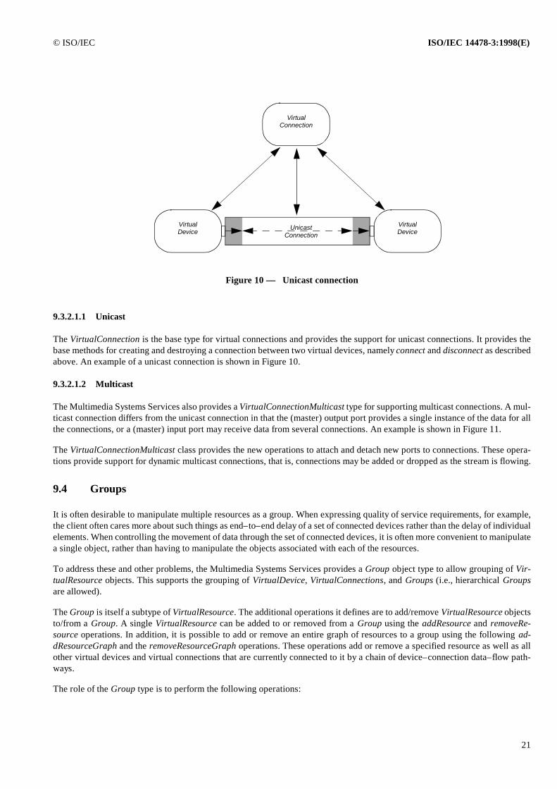
© ISO/IEC ISO/IEC 14478-3:1998(E)
21
9.3.2.1.1 Unicast
The VirtualConnection is the base type for virtual connections and provides the support for unicast connections. It provides thebase methods for creating and destroying a connection between two virtual devices, namely connect and disconnect as describedabove. An example of a unicast connection is shown in Figure 10.
9.3.2.1.2 Multicast
The Multimedia Systems Services also provides a VirtualConnectionMulticast type for supporting multicast connections. A mul-ticast connection differs from the unicast connection in that the (master) output port provides a single instance of the data for allthe connections, or a (master) input port may receive data from several connections. An example is shown in Figure 11.
The VirtualConnectionMulticast class provides the new operations to attach and detach new ports to connections. These opera-tions provide support for dynamic multicast connections, that is, connections may be added or dropped as the stream is flowing.
9.4 Groups
It is often desirable to manipulate multiple resources as a group. When expressing quality of service requirements, for example,the client often cares more about such things as end–to–end delay of a set of connected devices rather than the delay of individualelements. When controlling the movement of data through the set of connected devices, it is often more convenient to manipulatea single object, rather than having to manipulate the objects associated with each of the resources.
To address these and other problems, the Multimedia Systems Services provides a Group object type to allow grouping of Vir-tualResource objects. This supports the grouping of VirtualDevice, VirtualConnections, and Groups (i.e., hierarchical Groupsare allowed).
The Group is itself a subtype of VirtualResource. The additional operations it defines are to add/remove VirtualResource objectsto/from a Group. A single VirtualResource can be added to or removed from a Group using the addResource and removeRe-source operations. In addition, it is possible to add or remove an entire graph of resources to a group using the following ad-dResourceGraph and the removeResourceGraph operations. These operations add or remove a specified resource as well as allother virtual devices and virtual connections that are currently connected to it by a chain of device–connection data–flow path-ways.
The role of the Group type is to perform the following operations:
UnicastConnection
Figure 10 — Unicast connection
VirtualConnection
VirtualDevice
VirtualDevice
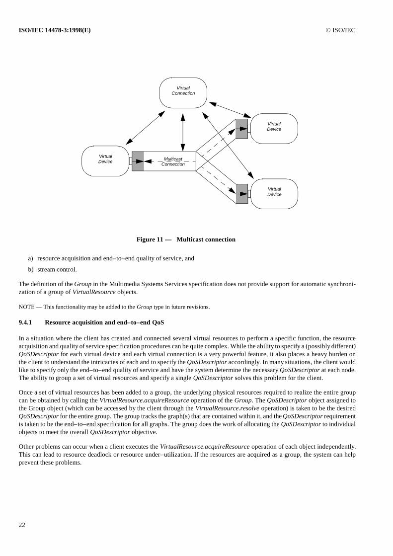
ISO/IEC 14478-3:1998(E) © ISO/IEC
22
a) resource acquisition and end–to–end quality of service, and
b) stream control.
The definition of the Group in the Multimedia Systems Services specification does not provide support for automatic synchroni-zation of a group of VirtualResource objects.
NOTE — This functionality may be added to the Group type in future revisions.
9.4.1 Resource acquisition and end–to–end QoS
In a situation where the client has created and connected several virtual resources to perform a specific function, the resourceacquisition and quality of service specification procedures can be quite complex. While the ability to specify a (possibly different)QoSDescriptor for each virtual device and each virtual connection is a very powerful feature, it also places a heavy burden onthe client to understand the intricacies of each and to specify the QoSDescriptor accordingly. In many situations, the client wouldlike to specify only the end–to–end quality of service and have the system determine the necessary QoSDescriptor at each node.The ability to group a set of virtual resources and specify a single QoSDescriptor solves this problem for the client.
Once a set of virtual resources has been added to a group, the underlying physical resources required to realize the entire groupcan be obtained by calling the VirtualResource.acquireResource operation of the Group. The QoSDescriptor object assigned tothe Group object (which can be accessed by the client through the VirtualResource.resolve operation) is taken to be the desiredQoSDescriptor for the entire group. The group tracks the graph(s) that are contained within it, and the QoSDescriptor requirementis taken to be the end–to–end specification for all graphs. The group does the work of allocating the QoSDescriptor to individualobjects to meet the overall QoSDescriptor objective.
Other problems can occur when a client executes the VirtualResource.acquireResource operation of each object independently.This can lead to resource deadlock or resource under–utilization. If the resources are acquired as a group, the system can helpprevent these problems.
Figure 11 — Multicast connection
MulticastConnection
VirtualConnection
VirtualDevice
VirtualDevice
VirtualDevice
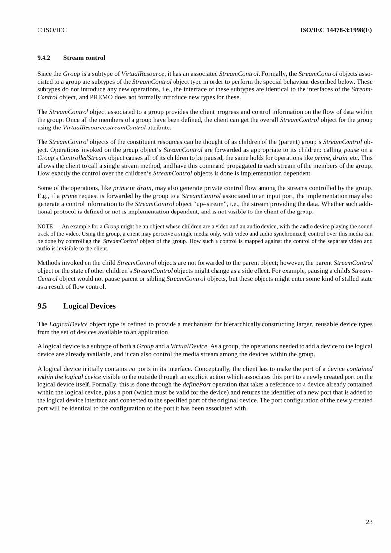
© ISO/IEC ISO/IEC 14478-3:1998(E)
23
9.4.2 Stream control
Since the Group is a subtype of VirtualResource, it has an associated StreamControl. Formally, the StreamControl objects asso-ciated to a group are subtypes of the StreamControl object type in order to perform the special behaviour described below. Thesesubtypes do not introduce any new operations, i.e., the interface of these subtypes are identical to the interfaces of the Stream-Control object, and PREMO does not formally introduce new types for these.
The StreamControl object associated to a group provides the client progress and control information on the flow of data withinthe group. Once all the members of a group have been defined, the client can get the overall StreamControl object for the groupusing the VirtualResource.streamControl attribute.
The StreamControl objects of the constituent resources can be thought of as children of the (parent) group’s StreamControl ob-ject. Operations invoked on the group object’s StreamControl are forwarded as appropriate to its children: calling pause on aGroup's ControlledStream object causes all of its children to be paused, the same holds for operations like prime, drain, etc. Thisallows the client to call a single stream method, and have this command propagated to each stream of the members of the group.How exactly the control over the children’s StreamControl objects is done is implementation dependent.
Some of the operations, like prime or drain, may also generate private control flow among the streams controlled by the group.E.g., if a prime request is forwarded by the group to a StreamControl associated to an input port, the implementation may alsogenerate a control information to the StreamControl object “up–stream”, i.e., the stream providing the data. Whether such addi-tional protocol is defined or not is implementation dependent, and is not visible to the client of the group.
NOTE — An example for a Group might be an object whose children are a video and an audio device, with the audio device playing the soundtrack of the video. Using the group, a client may perceive a single media only, with video and audio synchronized; control over this media canbe done by controlling the StreamControl object of the group. How such a control is mapped against the control of the separate video andaudio is invisible to the client.
Methods invoked on the child StreamControl objects are not forwarded to the parent object; however, the parent StreamControlobject or the state of other children’s StreamControl objects might change as a side effect. For example, pausing a child's Stream-Control object would not pause parent or sibling StreamControl objects, but these objects might enter some kind of stalled stateas a result of flow control.
9.5 Logical Devices
The LogicalDevice object type is defined to provide a mechanism for hierarchically constructing larger, reusable device typesfrom the set of devices available to an application
A logical device is a subtype of both a Group and a VirtualDevice. As a group, the operations needed to add a device to the logicaldevice are already available, and it can also control the media stream among the devices within the group.
A logical device initially contains no ports in its interface. Conceptually, the client has to make the port of a device containedwithin the logical device visible to the outside through an explicit action which associates this port to a newly created port on thelogical device itself. Formally, this is done through the definePort operation that takes a reference to a device already containedwithin the logical device, plus a port (which must be valid for the device) and returns the identifier of a new port that is added tothe logical device interface and connected to the specified port of the original device. The port configuration of the newly createdport will be identical to the configuration of the port it has been associated with.
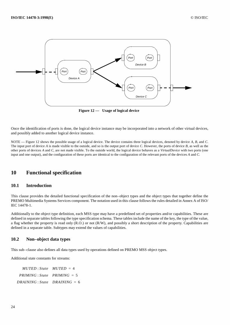
ISO/IEC 14478-3:1998(E) © ISO/IEC
24
Once the identification of ports is done, the logical device instance may be incorporated into a network of other virtual devices,and possibly added to another logical device instance.
NOTE — Figure 12 shows the possible usage of a logical device. The device contains three logical devices, denoted by device A, B, and C.The input port of device A is made visible to the outside, and so is the output port of device C. However, the ports of device B, as well as theother ports of devices A and C, are not made visible. To the outside world, the logical device behaves as a VirtualDevice with two ports (oneinput and one output), and the configuration of these ports are identical to the configuration of the relevant ports of the devices A and C.
10 Functional specification
10.1 Introduction
This clause provides the detailed functional specification of the non–object types and the object types that together define thePREMO Multimedia Systems Services component. The notation used in this clause follows the rules detailed in Annex A of ISO/IEC 14478-1.
Additionally to the object type definition, each MSS type may have a predefined set of properties and/or capabilities. These aredefined in separate tables following the type specification schema. These tables include the name of the key, the type of the value,a flag whether the property is read only (R.O.) or not (R/W), and possibly a short description of the property. Capabilities aredefined in a separate table. Subtypes may extend the values of capabilities.
10.2 Non–object data types
This sub–clause also defines all data types used by operations defined on PREMO MSS object types.
Additional state constants for streams:
Figure 12 — Usage of logical device
PortPort
PortPort
PortPort
Device A
Device B
Device C
MUTED State MUTED: 4=
PRIMING State PRIMING: 5=
DRAINING State DRAINING: 6=
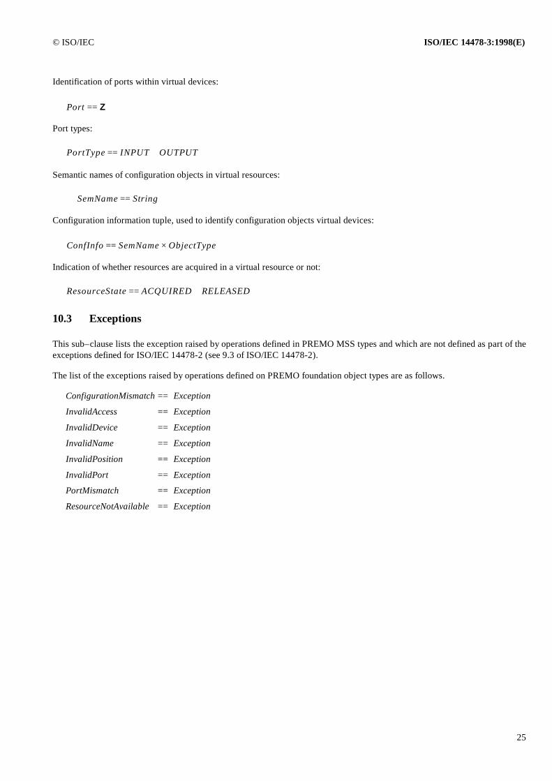
© ISO/IEC ISO/IEC 14478-3:1998(E)
25
Identification of ports within virtual devices:
Port types:
Semantic names of configuration objects in virtual resources:
Configuration information tuple, used to identify configuration objects virtual devices:
Indication of whether resources are acquired in a virtual resource or not:
10.3 Exceptions
This sub–clause lists the exception raised by operations defined in PREMO MSS types and which are not defined as part of theexceptions defined for ISO/IEC 14478-2 (see 9.3 of ISO/IEC 14478-2).
The list of the exceptions raised by operations defined on PREMO foundation object types are as follows.
ConfigurationMismatch == Exception
InvalidAccess == Exception
InvalidDevice == Exception
InvalidName == Exception
InvalidPosition == Exception
InvalidPort == Exception
PortMismatch == Exception
ResourceNotAvailable == Exception
Port Z==
PortType INPUT OUTPUT==
SemName String==
ConfInfo SemName ObjectType×==
ResourceState ACQUIRED RELEASED==
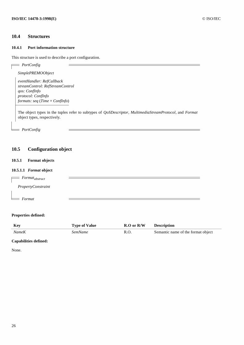
ISO/IEC 14478-3:1998(E) © ISO/IEC
26
10.4 Structures
10.4.1 Port information structure
This structure is used to describe a port configuration.
10.5 Configuration object
10.5.1 Format objects
10.5.1.1 Format object
Properties defined:
Capabilities defined:
None.
PortConfig
SimplePREMOObject
eventHandler: RefCallbackstreamControl: RefStreamControlqos: ConfInfoprotocol: ConfInfoformats: seq (Time × ConfInfo)
The object types in the tuples refer to subtypes of QoSDescriptor, MultimediaStreamProtocol, and Formatobject types, respectively.
PortConfig
Formatabstract
PropertyConstraint
Format
Key Type of Value R.O or R/W Description
NameK SemName R.O. Semantic name of the format object
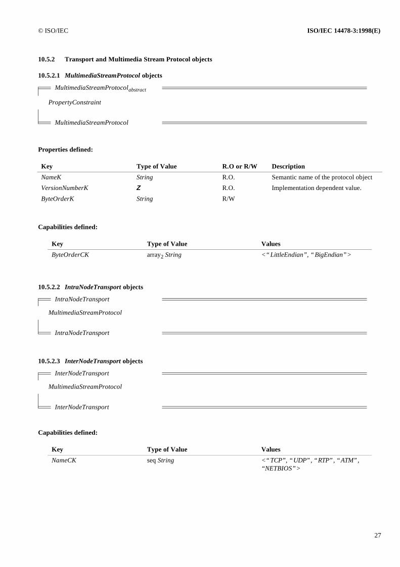
© ISO/IEC ISO/IEC 14478-3:1998(E)
27
10.5.2 Transport and Multimedia Stream Protocol objects
10.5.2.1 MultimediaStreamProtocol objects
Properties defined:
Capabilities defined:
10.5.2.2 IntraNodeTransport objects
10.5.2.3 InterNodeTransport objects
Capabilities defined:
MultimediaStreamProtocolabstract
PropertyConstraint
MultimediaStreamProtocol
Key Type of Value R.O or R/W Description
NameK String R.O. Semantic name of the protocol object
VersionNumberK Z R.O. Implementation dependent value.
ByteOrderK String R/W
Key Type of Value Values
ByteOrderCK array2 String <“LittleEndian”, “BigEndian”>
IntraNodeTransport
MultimediaStreamProtocol
IntraNodeTransport
InterNodeTransport
MultimediaStreamProtocol
InterNodeTransport
Key Type of Value Values
NameCK seq String <“TCP”, “UDP”, “RTP”, “ATM”,“NETBIOS”>
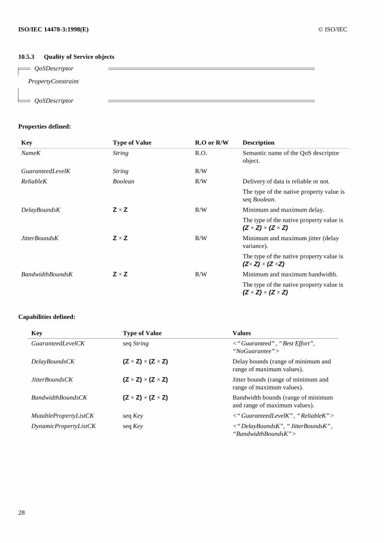
ISO/IEC 14478-3:1998(E) © ISO/IEC
28
10.5.3 Quality of Service objects
Properties defined:
Capabilities defined:
QoSDescriptor
PropertyConstraint
QoSDescriptor
Key Type of Value R.O or R/W Description
NameK String R.O. Semantic name of the QoS descriptor object.
GuaranteedLevelK String R/W
ReliableK Boolean R/W Delivery of data is reliable or not.
The type of the native property value isseq Boolean.
DelayBoundsK Z × Z R/W Minimum and maximum delay.
The type of the native property value is (Z × Z) × (Z × Z)
JitterBoundsK Z × Z R/W Minimum and maximum jitter (delay variance).
The type of the native property value is (Z× Z) × (Z ×Z)
BandwidthBoundsK Z × Z R/W Minimum and maximum bandwidth.
The type of the native property value is (Z × Z) × (Z × Z)
Key Type of Value Values
GuaranteedLevelCK seq String <“Guaranteed”, “Best Effort”, “NoGuarantee”>
DelayBoundsCK (Z × Z) × (Z × Z) Delay bounds (range of minimum and range of maximum values).
JitterBoundsCK (Z × Z) × (Z × Z) Jitter bounds (range of minimum and range of maximum values).
BandwidthBoundsCK (Z × Z) × (Z × Z) Bandwidth bounds (range of minimum and range of maximum values).
MutablePropertyListCK seq Key <“GuaranteedLevelK”, “ReliableK”>
DynamicPropertyListCK seq Key <“DelayBoundsK”, “JitterBoundsK”,“BandwidthBoundsK”>
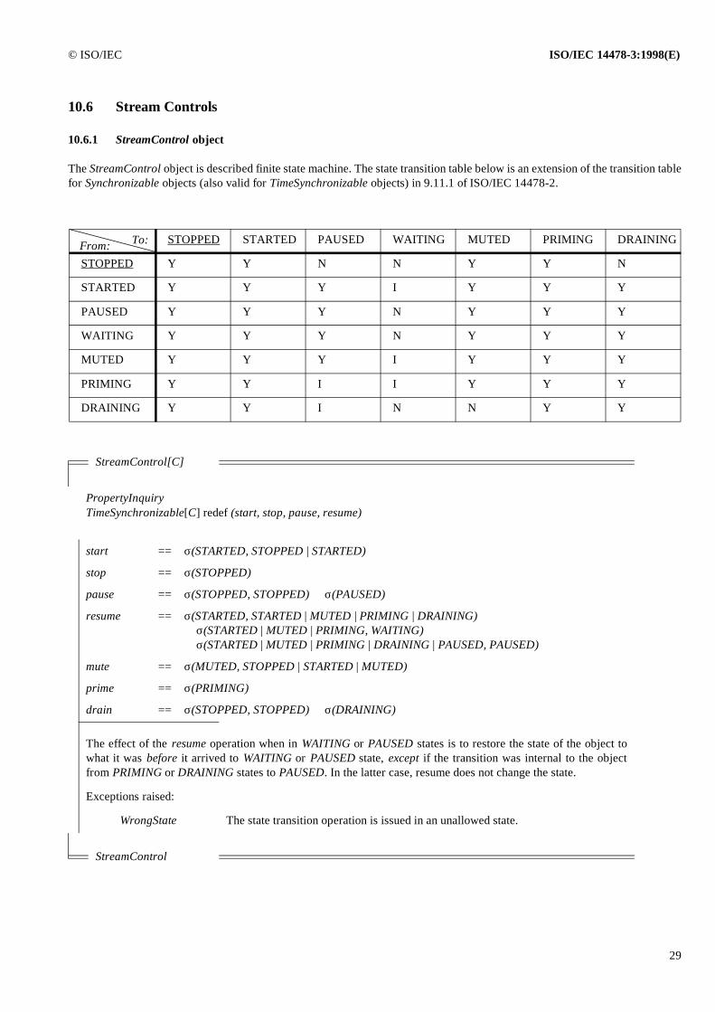
© ISO/IEC ISO/IEC 14478-3:1998(E)
29
10.6 Stream Controls
10.6.1 StreamControl object
The StreamControl object is described finite state machine. The state transition table below is an extension of the transition tablefor Synchronizable objects (also valid for TimeSynchronizable objects) in 9.11.1 of ISO/IEC 14478-2.
STOPPED STARTED PAUSED WAITING MUTED PRIMING DRAINING
STOPPED Y Y N N Y Y N
STARTED Y Y Y I Y Y Y
PAUSED Y Y Y N Y Y Y
WAITING Y Y Y N Y Y Y
MUTED Y Y Y I Y Y Y
PRIMING Y Y I I Y Y Y
DRAINING Y Y I N N Y Y
StreamControl[C]
PropertyInquiryTimeSynchronizable[C] redef (start, stop, pause, resume)
start == σ(STARTED, STOPPED | STARTED)
stop == σ(STOPPED)
pause == σ(STOPPED, STOPPED) ⊕ σ(PAUSED)
resume == σ(STARTED, STARTED | MUTED | PRIMING | DRAINING) ⊕ σ(STARTED | MUTED | PRIMING, WAITING)⊕ σ(STARTED | MUTED | PRIMING | DRAINING | PAUSED, PAUSED)
mute == σ(MUTED, STOPPED | STARTED | MUTED)
prime == σ(PRIMING)
drain == σ(STOPPED, STOPPED) ⊕ σ(DRAINING)
The effect of the resume operation when in WAITING or PAUSED states is to restore the state of the object towhat it was before it arrived to WAITING or PAUSED state, except if the transition was internal to the objectfrom PRIMING or DRAINING states to PAUSED. In the latter case, resume does not change the state.
Exceptions raised:
WrongState The state transition operation is issued in an unallowed state.
StreamControl
To:From:

ISO/IEC 14478-3:1998(E) © ISO/IEC
30
10.6.2 SyncStreamControl object
SyncStreamControl[C]
TimeSlave[C]StreamControl
SyncStreamControl
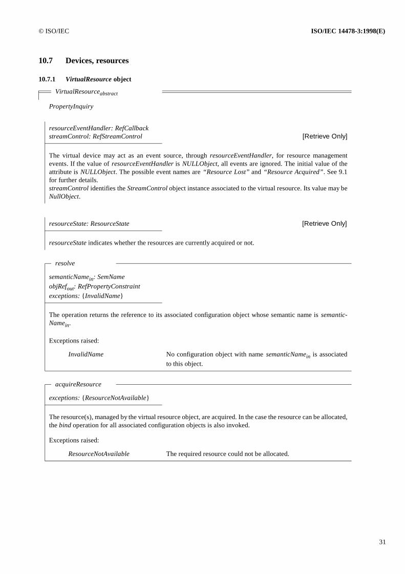
© ISO/IEC ISO/IEC 14478-3:1998(E)
31
10.7 Devices, resources
10.7.1 VirtualResource object
VirtualResourceabstract
PropertyInquiry
resourceEventHandler: RefCallbackstreamControl: RefStreamControl [Retrieve Only]
The virtual device may act as an event source, through resourceEventHandler, for resource managementevents. If the value of resourceEventHandler is NULLObject, all events are ignored. The initial value of theattribute is NULLObject. The possible event names are “Resource Lost” and “Resource Acquired”. See 9.1for further details.streamControl identifies the StreamControl object instance associated to the virtual resource. Its value may beNullObject.
resourceState: ResourceState [Retrieve Only]
resourceState indicates whether the resources are currently acquired or not.
resolve
semanticNamein: SemNameobjRefout: RefPropertyConstraintexceptions: {InvalidName}
The operation returns the reference to its associated configuration object whose semantic name is semantic-Namein.
Exceptions raised:
InvalidName No configuration object with name semanticNamein is associatedto this object.
acquireResource
exceptions: {ResourceNotAvailable}
The resource(s), managed by the virtual resource object, are acquired. In the case the resource can be allocated,the bind operation for all associated configuration objects is also invoked.
Exceptions raised:
ResourceNotAvailable The required resource could not be allocated.
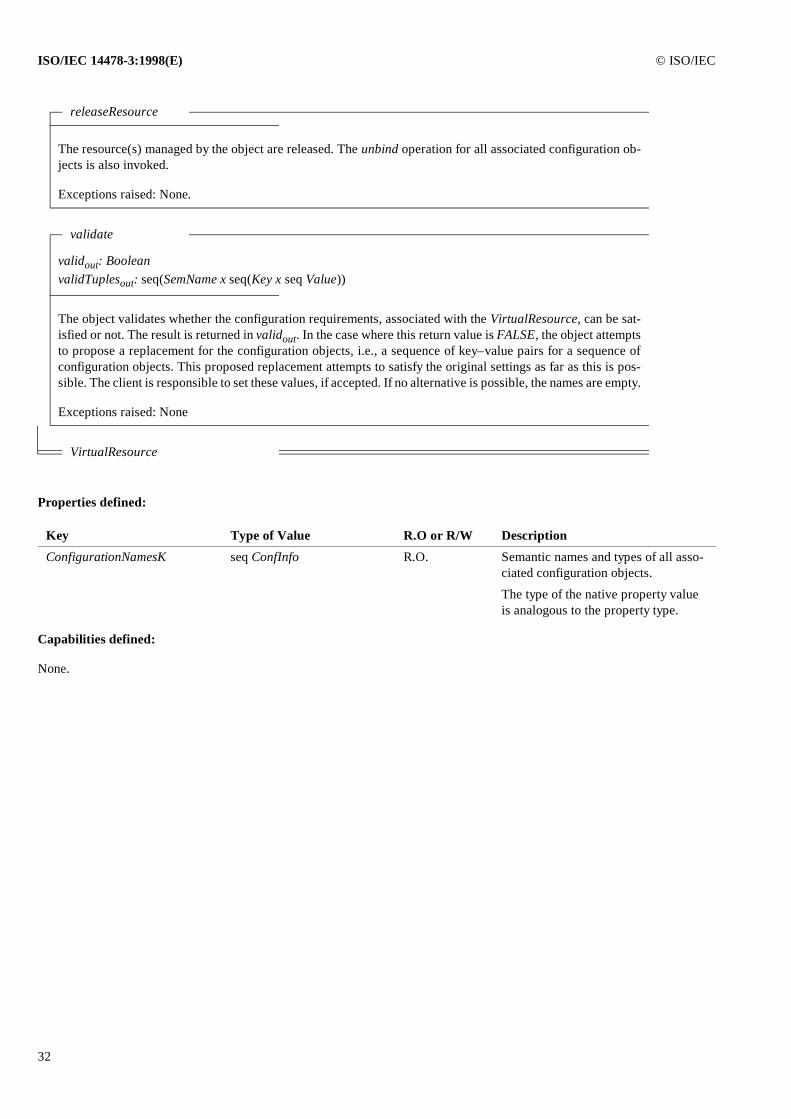
ISO/IEC 14478-3:1998(E) © ISO/IEC
32
Properties defined:
Capabilities defined:
None.
releaseResource
The resource(s) managed by the object are released. The unbind operation for all associated configuration ob-jects is also invoked.
Exceptions raised: None.
validate
validout: BooleanvalidTuplesout: seq(SemName x seq(Key x seq Value))
The object validates whether the configuration requirements, associated with the VirtualResource, can be sat-isfied or not. The result is returned in validout. In the case where this return value is FALSE, the object attemptsto propose a replacement for the configuration objects, i.e., a sequence of key–value pairs for a sequence ofconfiguration objects. This proposed replacement attempts to satisfy the original settings as far as this is pos-sible. The client is responsible to set these values, if accepted. If no alternative is possible, the names are empty.
Exceptions raised: None
VirtualResource
Key Type of Value R.O or R/W Description
ConfigurationNamesK seq ConfInfo R.O. Semantic names and types of all asso-ciated configuration objects.
The type of the native property value is analogous to the property type.
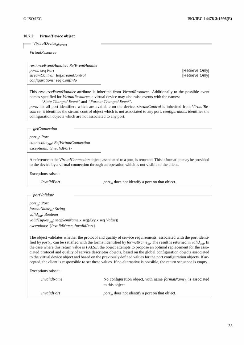
© ISO/IEC ISO/IEC 14478-3:1998(E)
33
10.7.2 VirtualDevice object
VirtualDeviceabstract
VirtualResource
resourceEventHandler: RefEventHandlerports: seq Port [Retrieve Only]streamControl: RefStreamControl [Retrieve Only]configurations: seq ConfInfo
This resourceEventHandler attribute is inherited from VirtualResource. Additionally to the possible eventnames specified for VirtualResource, a virtual device may also raise events with the names:
“State Changed Event” and “Format Changed Event”.ports list all port identifiers which are available on the device. streamControl is inherited from VirtualRe-source; it identifies the stream control object which is not associated to any port. configurations identifies theconfiguration objects which are not associated to any port.
getConnection
portin: Portconnectionout: RefVirtualConnectionexceptions: {InvalidPort}
A reference to the VirtualConnection object, associated to a port, is returned. This information may be providedto the device by a virtual connection through an operation which is not visible to the client.
Exceptions raised:
InvalidPort portin does not identify a port on that object.
portValidate
portin: PortformatNamein: Stringvalidout: BooleanvalidTuplesout: seq(SemName x seq(Key x seq Value))exceptions: {InvalidName, InvalidPort}
The object validates whether the protocol and quality of service requirements, associated with the port identi-fied by portin, can be satisfied with the format identified by formatNamein. The result is returned in validout. Inthe case where this return value is FALSE, the object attempts to propose an optimal replacement for the asso-ciated protocol and quality of service descriptor objects, based on the global configuration objects associatedto the virtual device object and based on the previously defined values for the port configuration objects. If ac-cepted, the client is responsible to set these values. If no alternative is possible, the return sequence is empty.
Exceptions raised:
InvalidName No configuration object, with name formatNamein is associatedto this object
InvalidPort portin does not identify a port on that object.
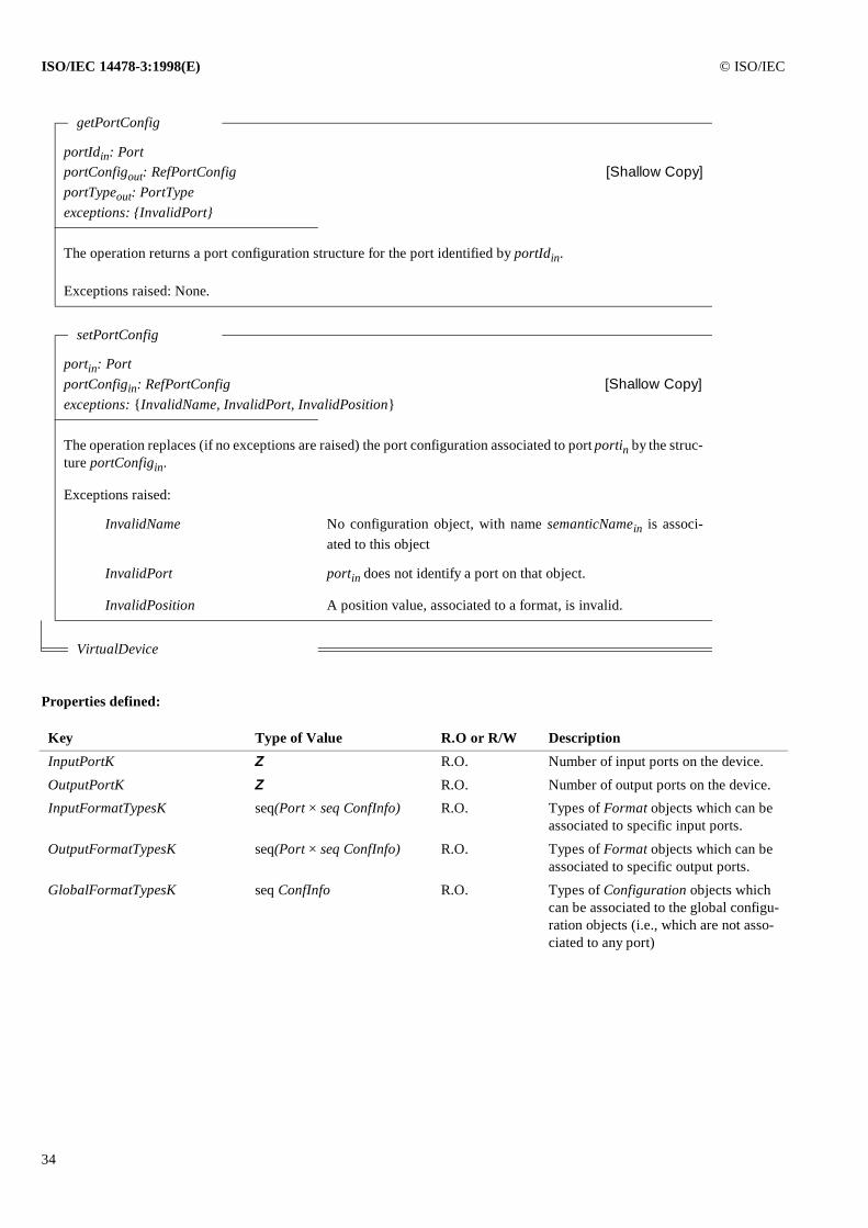
ISO/IEC 14478-3:1998(E) © ISO/IEC
34
Properties defined:
getPortConfig
portIdin: PortportConfigout: RefPortConfig [Shallow Copy]portTypeout: PortTypeexceptions: {InvalidPort}
The operation returns a port configuration structure for the port identified by portIdin.
Exceptions raised: None.
setPortConfig
portin: PortportConfigin: RefPortConfig [Shallow Copy]exceptions: {InvalidName, InvalidPort, InvalidPosition}
The operation replaces (if no exceptions are raised) the port configuration associated to port portin by the struc-ture portConfigin.
Exceptions raised:
InvalidName No configuration object, with name semanticNamein is associ-ated to this object
InvalidPort portin does not identify a port on that object.
InvalidPosition A position value, associated to a format, is invalid.
VirtualDevice
Key Type of Value R.O or R/W Description
InputPortK Z R.O. Number of input ports on the device.
OutputPortK Z R.O. Number of output ports on the device.
InputFormatTypesK seq(Port × seq ConfInfo) R.O. Types of Format objects which can be associated to specific input ports.
OutputFormatTypesK seq(Port × seq ConfInfo) R.O. Types of Format objects which can be associated to specific output ports.
GlobalFormatTypesK seq ConfInfo R.O. Types of Configuration objects which can be associated to the global configu-ration objects (i.e., which are not asso-ciated to any port)
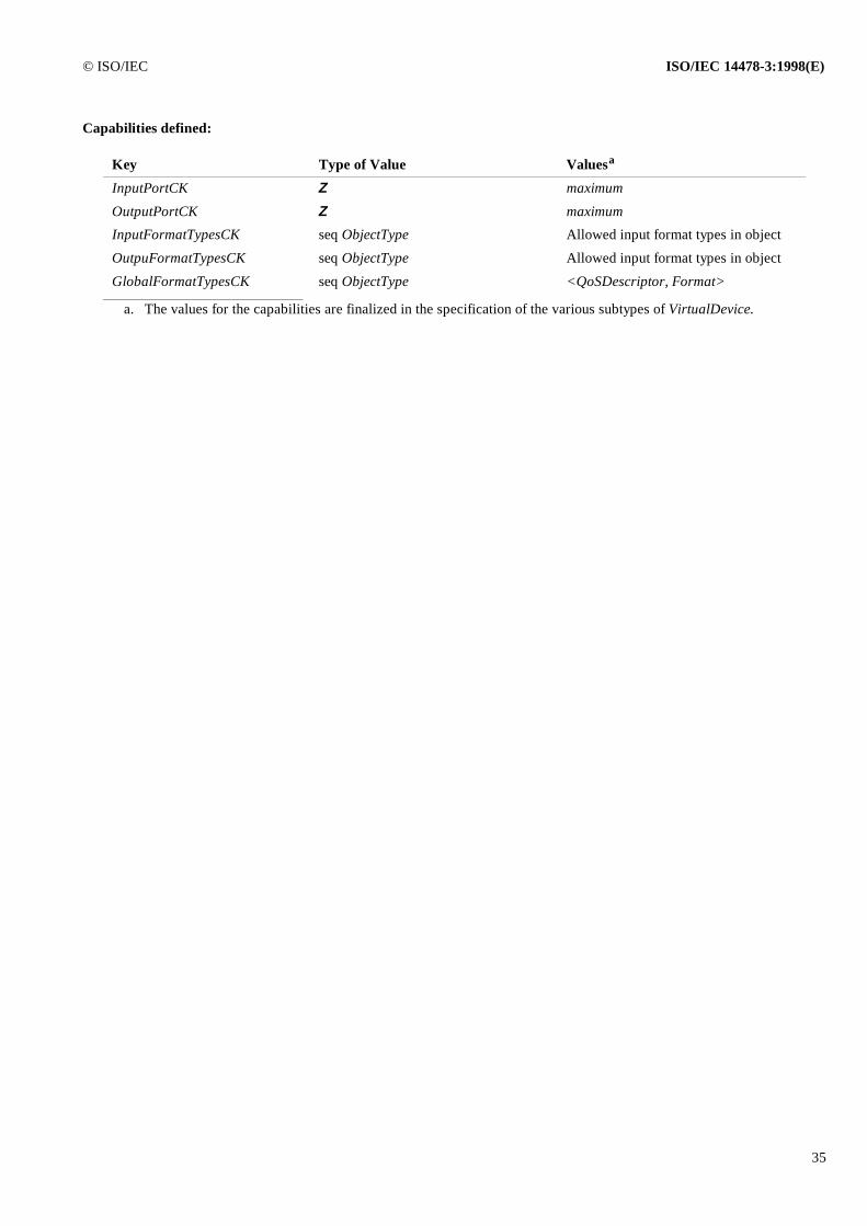
© ISO/IEC ISO/IEC 14478-3:1998(E)
35
Capabilities defined:
Key Type of Value Valuesa
a. The values for the capabilities are finalized in the specification of the various subtypes of VirtualDevice.
InputPortCK Z maximum
OutputPortCK Z maximum
InputFormatTypesCK seq ObjectType Allowed input format types in object
OutpuFormatTypesCK seq ObjectType Allowed input format types in object
GlobalFormatTypesCK seq ObjectType <QoSDescriptor, Format>
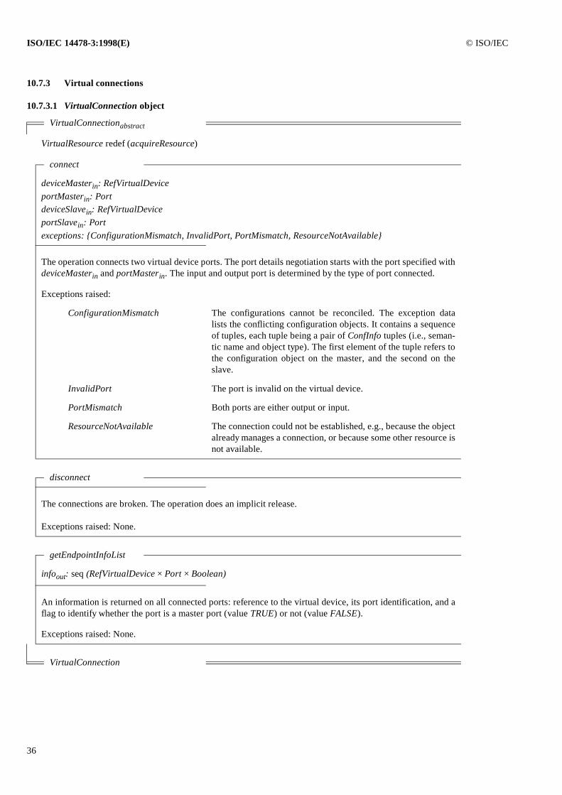
ISO/IEC 14478-3:1998(E) © ISO/IEC
36
10.7.3 Virtual connections
10.7.3.1 VirtualConnection object
VirtualConnectionabstract
VirtualResource redef (acquireResource)
connect
deviceMasterin: RefVirtualDeviceportMasterin: PortdeviceSlavein: RefVirtualDeviceportSlavein: Portexceptions: {ConfigurationMismatch, InvalidPort, PortMismatch, ResourceNotAvailable}
The operation connects two virtual device ports. The port details negotiation starts with the port specified withdeviceMasterin and portMasterin. The input and output port is determined by the type of port connected.
Exceptions raised:
ConfigurationMismatch The configurations cannot be reconciled. The exception datalists the conflicting configuration objects. It contains a sequenceof tuples, each tuple being a pair of ConfInfo tuples (i.e., seman-tic name and object type). The first element of the tuple refers tothe configuration object on the master, and the second on theslave.
InvalidPort The port is invalid on the virtual device.
PortMismatch Both ports are either output or input.
ResourceNotAvailable The connection could not be established, e.g., because the objectalready manages a connection, or because some other resource isnot available.
disconnect
The connections are broken. The operation does an implicit release.
Exceptions raised: None.
getEndpointInfoList
infoout: seq (RefVirtualDevice × Port × Boolean)
An information is returned on all connected ports: reference to the virtual device, its port identification, and aflag to identify whether the port is a master port (value TRUE) or not (value FALSE).
Exceptions raised: None.
VirtualConnection
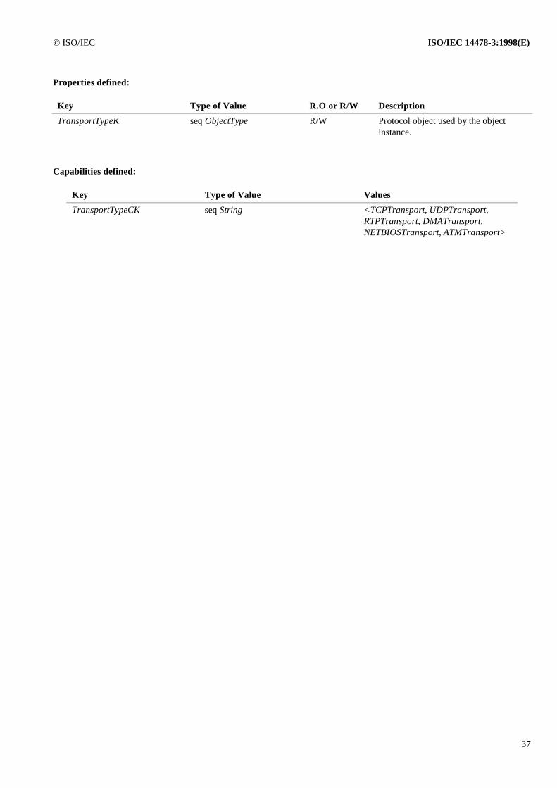
© ISO/IEC ISO/IEC 14478-3:1998(E)
37
Properties defined:
Capabilities defined:
Key Type of Value R.O or R/W Description
TransportTypeK seq ObjectType R/W Protocol object used by the object instance.
Key Type of Value Values
TransportTypeCK seq String <TCPTransport, UDPTransport,RTPTransport, DMATransport,NETBIOSTransport, ATMTransport>
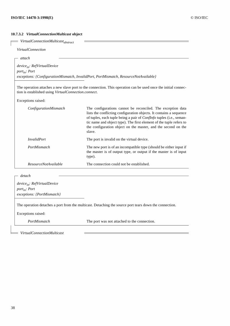
ISO/IEC 14478-3:1998(E) © ISO/IEC
38
10.7.3.2 VirtualConnectionMulticast object
VirtualConnectionMulticastabstract
VirtualConnection
attach
devicein: RefVirtualDeviceportin: Portexceptions: {ConfigurationMismatch, InvalidPort, PortMismatch, ResourceNotAvailable}
The operation attaches a new slave port to the connection. This operation can be used once the initial connec-tion is established using VirtualConnection.connect.
Exceptions raised:
ConfigurationMismatch The configurations cannot be reconciled. The exception datalists the conflicting configuration objects. It contains a sequenceof tuples, each tuple being a pair of ConfInfo tuples (i.e., seman-tic name and object type). The first element of the tuple refers tothe configuration object on the master, and the second on theslave.
InvalidPort The port is invalid on the virtual device.
PortMismatch The new port is of an incompatible type (should be either input ifthe master is of output type, or output if the master is of inputtype).
ResourceNotAvailable The connection could not be established.
detach
devicein: RefVirtualDeviceportin: Portexceptions: {PortMismatch}
The operation detaches a port from the multicast. Detaching the source port tears down the connection.
Exceptions raised:
PortMismatch The port was not attached to the connection.
VirtualConnectionMulticast
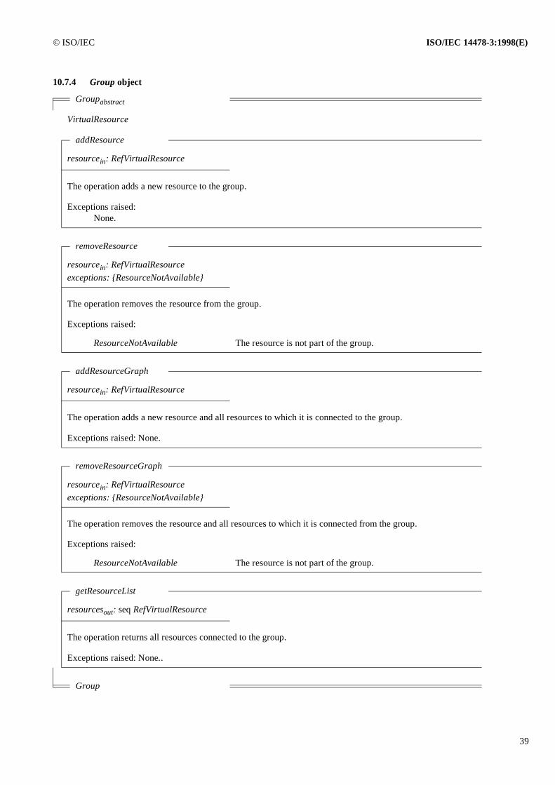
© ISO/IEC ISO/IEC 14478-3:1998(E)
39
10.7.4 Group object
Groupabstract
VirtualResource
addResource
resourcein: RefVirtualResource
The operation adds a new resource to the group.
Exceptions raised:None.
removeResource
resourcein: RefVirtualResourceexceptions: {ResourceNotAvailable}
The operation removes the resource from the group.
Exceptions raised:
ResourceNotAvailable The resource is not part of the group.
addResourceGraph
resourcein: RefVirtualResource
The operation adds a new resource and all resources to which it is connected to the group.
Exceptions raised: None.
removeResourceGraph
resourcein: RefVirtualResourceexceptions: {ResourceNotAvailable}
The operation removes the resource and all resources to which it is connected from the group.
Exceptions raised:
ResourceNotAvailable The resource is not part of the group.
getResourceList
resourcesout: seq RefVirtualResource
The operation returns all resources connected to the group.
Exceptions raised: None..
Group
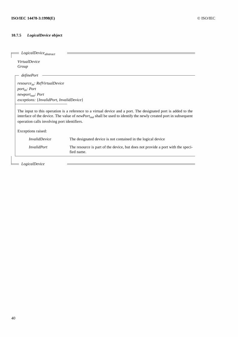
ISO/IEC 14478-3:1998(E) © ISO/IEC
40
10.7.5 LogicalDevice object
LogicalDeviceabstract
VirtualDeviceGroup
definePort
resourcein: RefVirtualDeviceportin: Portnewportout: Portexceptions: {InvalidPort, InvalidDevice}
The input to this operation is a reference to a virtual device and a port. The designated port is added to theinterface of the device. The value of newPortout shall be used to identify the newly created port in subsequentoperation calls involving port identifiers.
Exceptions raised:
InvalidDevice The designated device is not contained in the logical device
InvalidPort The resource is part of the device, but does not provide a port with the speci-fied name.
LogicalDevice
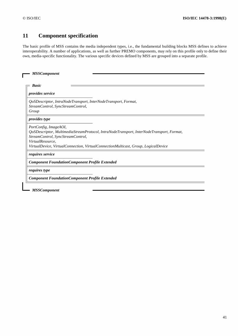
© ISO/IEC ISO/IEC 14478-3:1998(E)
41
11 Component specification
The basic profile of MSS contains the media independent types, i.e., the fundamental building blocks MSS defines to achieveinteroperability. A number of applications, as well as further PREMO components, may rely on this profile only to define theirown, media-specific functionality. The various specific devices defined by MSS are grouped into a separate profile.
MSSComponent
Basic
provides service
QoSDescriptor, IntraNodeTransport, InterNodeTransport, Format,StreamControl, SyncStreamControl,Group
provides type
PortConfig, ImageAOI,QoSDescriptor, MultimediaStreamProtocol, IntraNodeTransport, InterNodeTransport, Format,StreamControl, SyncStreamControl,VirtualResource, VirtualDevice, VirtualConnection, VirtualConnectionMulticast, Group, LogicalDevice
requires service
Component FoundationComponent Profile Extended
requires type
Component FoundationComponent Profile Extended
MSSComponent
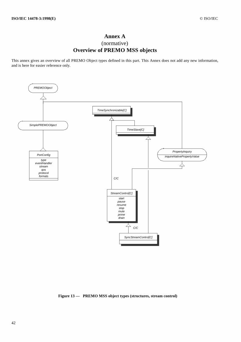
ISO/IEC 14478-3:1998(E) © ISO/IEC
42
Annex A (normative)
Overview of PREMO MSS objects
This annex gives an overview of all PREMO Object types defined in this part. This Annex does not add any new information,and is here for easier reference only.
Figure 13 — PREMO MSS object types (structures, stream control)
SimplePREMOObject
PREMOObject
PortConfig
typeeventHandler
streamqos
protocolformats
PropertyInquiry
inquireNativePropertyValue
TimeSlave[C]
StreamControl[C]
startpause
resumestopmuteprimedrain
SyncStreamControl[C]
C/C
C/C
TimeSynchronizable[C]
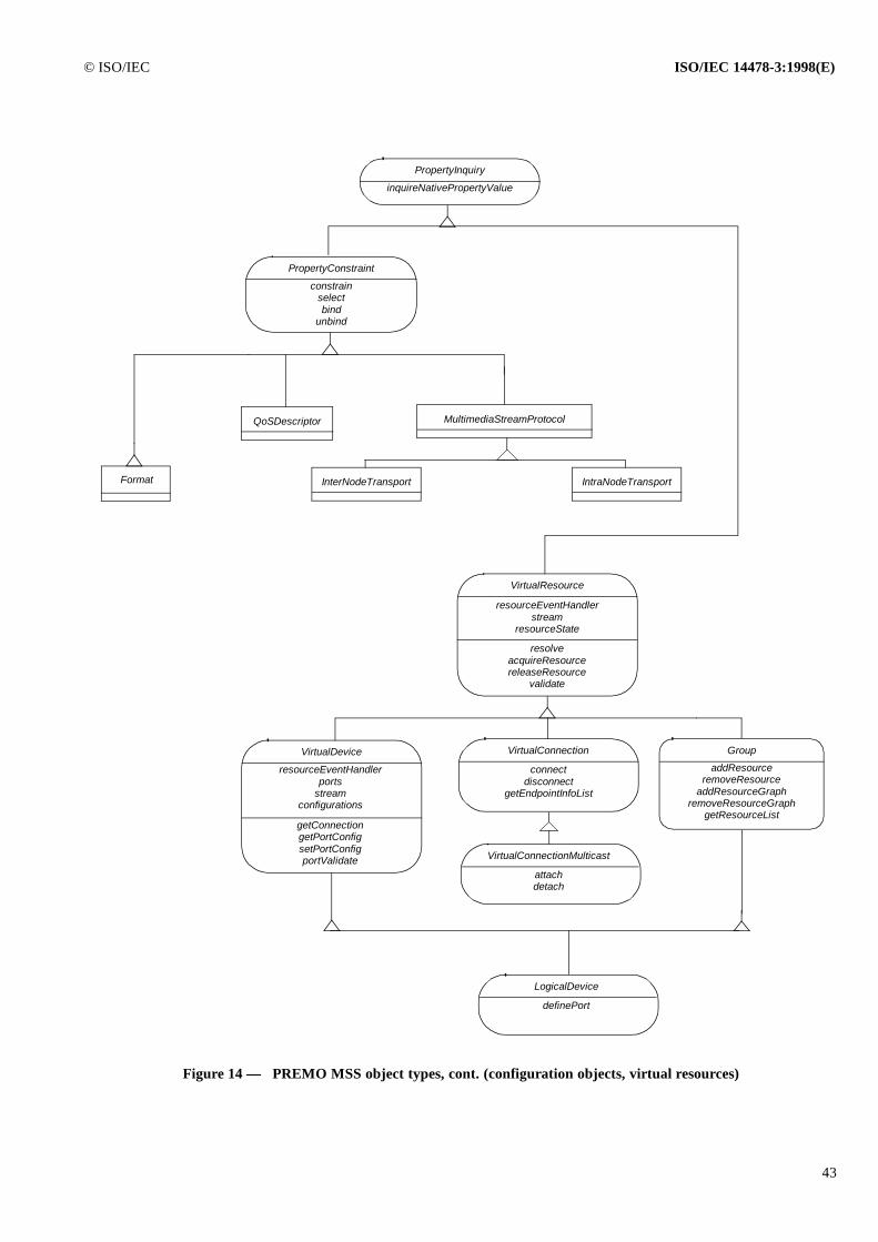
© ISO/IEC ISO/IEC 14478-3:1998(E)
43
PropertyInquiry
inquireNativePropertyValue
PropertyConstraint
constrainselectbind
unbind
Format
MultimediaStreamProtocol
InterNodeTransport
QoSDescriptor
Figure 14 — PREMO MSS object types, cont. (configuration objects, virtual resources)
IntraNodeTransport
VirtualResource
resolveacquireResourcereleaseResource
validate
resourceEventHandlerstream
resourceState
VirtualDevice
getConnectiongetPortConfigsetPortConfigportValidate
VirtualConnection
connectdisconnect
getEndpointInfoList
VirtualConnectionMulticast
attachdetach
Group
addResourceremoveResource
addResourceGraphremoveResourceGraph
getResourceList
resourceEventHandlerports
streamconfigurations
LogicalDevice
definePort
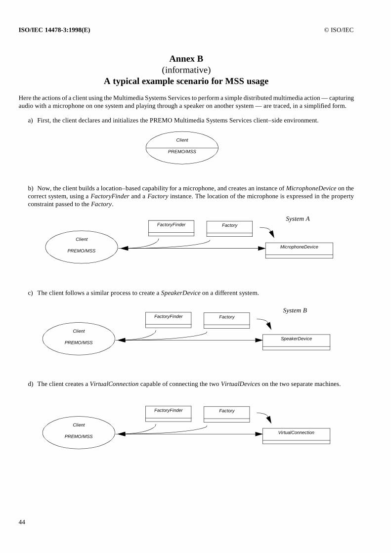
ISO/IEC 14478-3:1998(E) © ISO/IEC
44
Annex B (informative)
A typical example scenario for MSS usage
Here the actions of a client using the Multimedia Systems Services to perform a simple distributed multimedia action — capturingaudio with a microphone on one system and playing through a speaker on another system — are traced, in a simplified form.
a) First, the client declares and initializes the PREMO Multimedia Systems Services client–side environment.
b) Now, the client builds a location–based capability for a microphone, and creates an instance of MicrophoneDevice on thecorrect system, using a FactoryFinder and a Factory instance. The location of the microphone is expressed in the propertyconstraint passed to the Factory.
c) The client follows a similar process to create a SpeakerDevice on a different system.
d) The client creates a VirtualConnection capable of connecting the two VirtualDevices on the two separate machines.
Client
PREMO/MSS
Client
PREMO/MSS
FactoryFinder Factory
MicrophoneDevice
System A
Client
PREMO/MSS
FactoryFinder Factory
SpeakerDevice
System B
Client
PREMO/MSS
FactoryFinder Factory
VirtualConnection
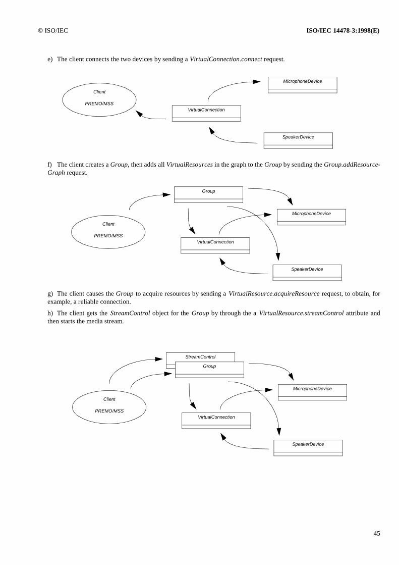
© ISO/IEC ISO/IEC 14478-3:1998(E)
45
e) The client connects the two devices by sending a VirtualConnection.connect request.
f) The client creates a Group, then adds all VirtualResources in the graph to the Group by sending the Group.addResource-Graph request.
g) The client causes the Group to acquire resources by sending a VirtualResource.acquireResource request, to obtain, forexample, a reliable connection.
h) The client gets the StreamControl object for the Group by through the a VirtualResource.streamControl attribute andthen starts the media stream.
Client
PREMO/MSSVirtualConnection
MicrophoneDevice
SpeakerDevice
Client
PREMO/MSSVirtualConnection
MicrophoneDevice
SpeakerDevice
Group
StreamControl
Client
PREMO/MSSVirtualConnection
MicrophoneDevice
SpeakerDevice
Group
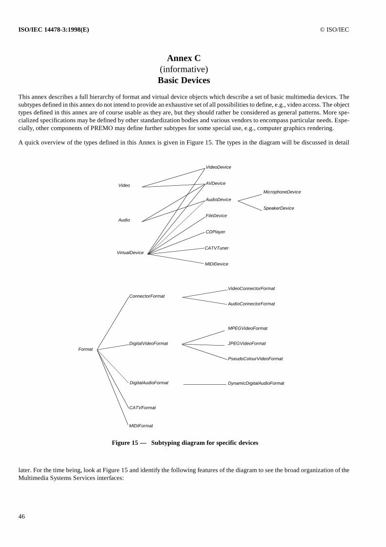
ISO/IEC 14478-3:1998(E) © ISO/IEC
46
Annex C (informative)Basic Devices
This annex describes a full hierarchy of format and virtual device objects which describe a set of basic multimedia devices. Thesubtypes defined in this annex do not intend to provide an exhaustive set of all possibilities to define, e.g., video access. The objecttypes defined in this annex are of course usable as they are, but they should rather be considered as general patterns. More spe-cialized specifications may be defined by other standardization bodies and various vendors to encompass particular needs. Espe-cially, other components of PREMO may define further subtypes for some special use, e.g., computer graphics rendering.
A quick overview of the types defined in this Annex is given in Figure 15. The types in the diagram will be discussed in detail
later. For the time being, look at Figure 15 and identify the following features of the diagram to see the broad organization of theMultimedia Systems Services interfaces:
Format
ConnectorFormat
DigitalVideoFormat
DigitalAudioFormat
CATVFormat
VideoConnectorFormat
AudioConnectorFormat
MPEGVideoFormat
JPEGVideoFormat
PseudoColourVideoFormat
DynamicDigitalAudioFormat
CATVTuner
CDPlayer
FileDevice
AudioDevice
AVDevice
VideoDevice
VirtualDevice
MicrophoneDevice
SpeakerDevice
Audio
Video
Figure 15 — Subtyping diagram for specific devices
MIDIDevice
MIDIFormat
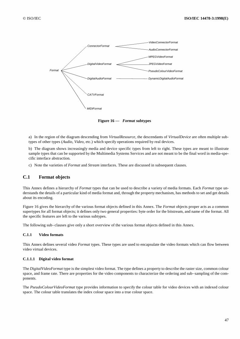
© ISO/IEC ISO/IEC 14478-3:1998(E)
47
a) In the region of the diagram descending from VirtualResource, the descendants of VirtualDevice are often multiple sub-types of other types (Audio, Video, etc.) which specify operations required by real devices.
b) The diagram shows increasingly media and device specific types from left to right. These types are meant to illustratesample types that can be supported by the Multimedia Systems Services and are not meant to be the final word in media-spe-cific interface abstraction.
c) Note the varieties of Format and Stream interfaces. These are discussed in subsequent clauses.
C.1 Format objects
This Annex defines a hierarchy of Format types that can be used to describe a variety of media formats. Each Format type un-derstands the details of a particular kind of media format and, through the property mechanism, has methods to set and get detailsabout its encoding.
Figure 16 gives the hierarchy of the various format objects defined in this Annex. The Format objects proper acts as a commonsupertypes for all format objects; it defines only two general properties: byte order for the bitstream, and name of the format. Allthe specific features are left to the various subtypes.
The following sub–clauses give only a short overview of the various format objects defined in this Annex.
C.1.1 Video formats
This Annex defines several video Format types. These types are used to encapsulate the video formats which can flow betweenvideo virtual devices.
C.1.1.1 Digital video format
The DigitalVideoFormat type is the simplest video format. The type defines a property to describe the raster size, common colourspace, and frame rate. There are properties for the video components to characterize the ordering and sub–sampling of the com-ponents.
The PseudoColourVideoFormat type provides information to specify the colour table for video devices with an indexed colourspace. The colour table translates the index colour space into a true colour space.
Figure 16 — Format subtypes
Format
ConnectorFormat
DigitalVideoFormat
DigitalAudioFormat
CATVFormat
VideoConnectorFormat
AudioConnectorFormat
MPEGVideoFormat
JPEGVideoFormat
PseudoColourVideoFormat
DynamicDigitalAudioFormat
MIDIFormat
ISO/IEC 14478-3:1998(E) © ISO/IEC
48
The JPEGVideoFormat type defines the segment keys which this compression technique requires. These segment keys representin–band control messages. For example, the key JPEGVideoFormat::DqtK defines the quantization table. This video format il-lustrates how the format object can encapsulate dynamic formats which encode commands into the data stream.
The MPEGVideoFormat interface defines properties for this compression technique. The list of keys is extensive. The allocationof these details to the format type, however, consolidates the conventions to one interface.
C.1.1.2 External video format
This Annex defines some additional external video format properties. These format keys anticipate the integration of device con-trol into the framework. Assume someone provides a virtual device object which provides the type to control a VCR device. Thevirtual device would describe the video stream which it can export in terms of a video format object. Assume the framework alsoprovides a video capture device. Since both virtual devices describe video formats, the client (or the connection object) can verifythe formats are compatible. For example, the key “EncodingK” for the VideoConnectorFormat object may have the value of “NT-SC”, “PAL”, “SECAM”, “RGB”, “YUV”, “AUTO” to describe the various available formats for digital and analogue video.
C.1.2 Audio formats
This Annex offers three audio specific format types. These types are used to abstract the format of audio data that can flow acrossconnections and be produced or consumed by audio-capable virtual devices.
C.1.2.1 Digital Audio Format
The DigitalAudioFormat type is intended to abstract the set of audio formats. Its characteristics are those that are necessary tofully specify a digital audio bitstream, and they include such things as encoding, sample rate, and bits per sample.
The special properties of the DigitalAudioFormat are such that they cannot be changed once either of the following two condi-tions occur:
a) The port with which it is associated is connected to another virtual device (see clause 9) via the connect operation; or
b) The VirtualDevice, VirtualConnection, or Group with which it is associated has its resources acquired via the acquireRe-source operation.
The reason for the first condition is that the data format abstracted by DigitalAudioFormat does not define any in–band signallingof changes in its characteristics, such as sample rate. The VirtualConnection establishes an agreement between the source anddestination format objects; changing the value of a characteristic of one of the format objects on the fly violates this agreementand could cause data flowing through the connection to be misinterpreted.
The reason for the second condition is that the resources required to process or transport the audio data are dependent on the set-tings of the DigitalAudioFormat characteristics. Once the VirtualResource.acquireResource operation is invoked, a quality ofservice contract is established; changing the constraint on the properties of a format object may cause this contract to be violated.
C.1.2.1.1 Dynamic Digital Audio Format
The DynamicDigitalAudioFormat type is a subtype of the DigitalAudioFormat type. It defines no new methods or properties, butit is intended to abstract audio data formats that provide the in–band signalling necessary to change values of its characteristics,such as sample rate, on the fly.
Because of the in–band signalling capability, the conditions that prevented the characteristic settings of a DigitalAudioFormatobject from being changed do not prevent the characteristic settings of a DynamicDigitalAudioFormat object from beingchanged. However, the client should be careful to constrain the range of characteristic settings to those it expects to use in orderto improve the chances of a successful connection and to prevent over–allocation of resources.
© ISO/IEC ISO/IEC 14478-3:1998(E)
49
C.1.2.2 Audio Connector Format
The AudioConnector interface abstracts audio formats that are made external to a computer system, such as line, headphones,and microphone level analogue signals. The properties of this format are used to determine the compatibility of data types in thesame way as for internal digital audio data types. For example, it is possible to determine that a port that uses a line level cannotbe connected to a port that uses a headphones level.
The AudioConnectorFormat is an example of a Format type that is associated with VirtualDevice ports that model physical con-nections to a device. Exposing the physical connectors of a device as ports and describing the data that can flow across them asFormats permits external devices to be modelled in exactly the same way as internal devices.
C.1.3 CATV format
CATV is the acronym for Cable TV. The CATVFormat object gives a standardized way to describe access to CATV networkinformation.
C.1.4 MIDI format
MIDI is the acronym for Musical Instrument Digital Interface, used to interface synthesizers, sequencers, rhythm machines, etc.All MIDI communication is achieved through multi–byte messages which are defined in separate specifications. The MIDIFor-mat object gives a standardized way to interface such devices.
C.2 Digital stream controls
All devices, described in this Annex, use digital stream control. This means that the generic SyncStream and SyncStreamControlobjects, as defined in clause 8, are actualized so that their progression space is defined to be Z∞, and all virtual device objects inthis Annex used these objects instead of the general ones.
C.3 Video and audio processing
C.3.1 Video processing
The basic video specific processing interface is defined by the Video type. This is an abstract base type that is “mixed in” withthe VirtualDevice type through multiple subtyping to create the VideoDevice interface.
The Video type was made a distinct type itself, rather than defining its methods directly in the VideoDevice type defined later, inorder to allow adding video processing operations to other types of devices (such as an audio/video device) without encounteringambiguous multiple subtyping. This approach ensures that there is exactly one path from a VirtualDevice subtype to its basetypes.
The interface of the type allows the client to manipulate standard video controls. Since devices often provide additional controls,the interface casts the controls as a property list. With this syntax it is straightforward to define additional KeyValue pairs, andstill inherit the operations found in the video type. Note that since the operations includes the stream position, the client can en-queue methods which modify the controls as a function of the steam time.
The interface of the Video type provides an operation to set the Area Of Interest within the source raster. The structure to definean area of interest describes the origin (x,y) and size (width,height) within the source raster which the object is to process. Notethat the width and height can assume negative values. The four combinations of positive and negative values allow the client toreflect the image across either or both of the vertical and horizontal axes.
The operation which specifies the area of interest (setImageAOI) also takes a stream position (i.e., stream relative time) argumentto allow for changes in the area of interest as the stream flows. The current value of the area of interest can also be inquired. Also,since the region within the source raster can be larger than the target raster, there is a property to specify whether the object is toclip or scale.
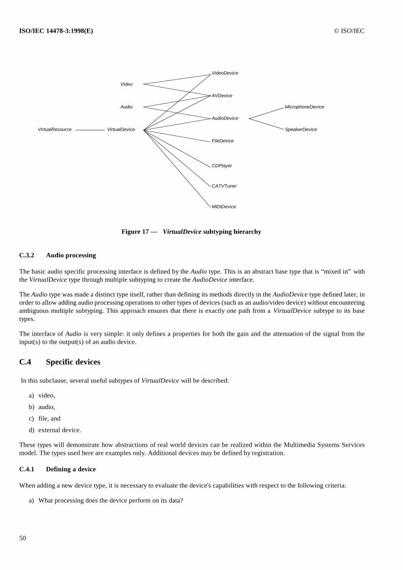
ISO/IEC 14478-3:1998(E) © ISO/IEC
50
C.3.2 Audio processing
The basic audio specific processing interface is defined by the Audio type. This is an abstract base type that is “mixed in” withthe VirtualDevice type through multiple subtyping to create the AudioDevice interface.
The Audio type was made a distinct type itself, rather than defining its methods directly in the AudioDevice type defined later, inorder to allow adding audio processing operations to other types of devices (such as an audio/video device) without encounteringambiguous multiple subtyping. This approach ensures that there is exactly one path from a VirtualDevice subtype to its basetypes.
The interface of Audio is very simple: it only defines a properties for both the gain and the attenuation of the signal from theinput(s) to the output(s) of an audio device.
C.4 Specific devices
In this subclause, several useful subtypes of VirtualDevice will be described:
a) video,
b) audio,
c) file, and
d) external device.
These types will demonstrate how abstractions of real world devices can be realized within the Multimedia Systems Servicesmodel. The types used here are examples only. Additional devices may be defined by registration.
C.4.1 Defining a device
When adding a new device type, it is necessary to evaluate the device's capabilities with respect to the following criteria:
a) What processing does the device perform on its data?
VirtualResource
CATVTuner
CDPlayer
FileDevice
AudioDevice
AVDevice
VideoDevice
VirtualDevice
MicrophoneDevice
SpeakerDevice
Audio
Video
Figure 17 — VirtualDevice subtyping hierarchy
MIDIDevice
© ISO/IEC ISO/IEC 14478-3:1998(E)
51
b) What types of data can be processed? What characteristics define them?
c) What stream position and control vocabulary is needed?
The answer to the first question determines the new operations that the new VirtualDevice subtype should have. The answer tothe second question determines what new Format and possibly Protocol type(s) are necessary to configure the ports. The answerto the third question determines if any new StreamControl subtype or position keys may be needed.
In addition, one should consider what the configuration of the device's ports should be. Typically, each point to which a connec-tion can be made (either virtual or physical) should be exposed as a virtual device port. For example, an audio digitizer devicethat can input data from a line input and produce a stream of digital data would have one input and one output port; in contrast,a speaker device that can input data from a digital stream and produce sound would have one input port and no output ports.
C.4.2 Video
Most of the general characteristics of video processing are abstracted in the separate Video object type (see Annex C.3 of thisPart), as well as in the various video related Format types (see Annex C.1 of this Part). No new stream control vocabulary isnecessary. This Annex of PREMO defines only one VideoDevice type; the definition of specific subtypes for various operatingenvironments would go beyond the scope of this Annex and should refer to the special features of these environments.
NOTE — Informal ISO documents or appendices to this standard may however be published to give a general highlight of how this could bedone for specific environments.
C.4.3 Audio
The addition of audio devices to this Annex involves the definition of audio specific processing capabilities and media formats.No new stream control vocabulary is necessary.
C.4.3.1 Audio processing
The basic audio specific processing interface is defined by the Audio interface (see Annex C.3.2 of this Part). This type is anabstract base type that is “mixed in” with the VirtualDevice type to create the AudioDevice type. In addition, certain characteris-tics specific to audio processing are defined, such as the encoding and sample rate associated with the inputs and outputs; thisdefines a vocabulary sufficient for the client to specify simple constraints about the type of AudioDevice, such as “an Audio De-vice that can process 44.1 KHz at its input and produce 8 KHz at its output”.
The AudioDevice interface can be used to represent any device that processes audio and supports the gain and attenuation prop-erties. If a device is incapable of affecting the gain, it can either be represented as an AudioDevice with its gain value fixed atunity, or simply as a VirtualDevice that admits to audio Format objects at its ports (see below).
C.4.3.1.1 Speaker device
The SpeakerDevice is a subtype of the AudioDevice type. It is used to abstract a built–in speaker device. This device presents oneinput port and has no output ports (it just pushes air). It defines no new operations.
The SpeakerDevice type is defined to make an easy distinction for the client between this type of device and, say, an audio displaydevice that drives a line output. Both can be equally well represented by the AudioDevice interface. The SpeakerDevice type pro-vides a simple way for the client to get a speaker, without having to set the appropriate constraints on a generic AudioDevice.
C.4.3.1.2 Microphone device
The MicrophoneDevice is a subtype of AudioDevice. It is used to abstract a built–in microphone device. It presents one outputport and no input ports. Like SpeakerDevice, it is defined as a simple way for a client to obtain a microphone, without having toset the appropriate constraints on a generic AudioDevice.

ISO/IEC 14478-3:1998(E) © ISO/IEC
52
C.4.4 Files
A pervasive characteristic of multimedia applications is the use of files to store and play back media. Defining a separate deviceto describe file processing in a multimedia setting gives a high level of uniformity to multimedia applications.
Common to the processing of most media file types is a core set of operations required by clients for the playback and storage ofmedia data. These operations include:
a) setting the mode for file access, e.g., read, write;
b) identifying the file format type;
c) inquiry on file and data characteristics;
d) setting the position within the file for data access;
e) setting ranges within the file to constrain data access;
f) repetitive data access; and
g) controlling the speed of playback.
Files introduce no new media formats, but rather use the same Format objects as already defined for the media-specific device(i.e., DigitalAudioFormat, DigitalVideoFormat, etc.). The operations unique to particular file formats are supplied by subtypingthe VirtualDevice type.
The specific characteristics of a file virtual device are determined by the file format type which it represents and its mode of op-eration, e.g., reading or writing. Several approaches are possible for managing the process of discovering the file's type andlaunching the appropriate file reader or writer device. One fairly simple strategy is to assume that the client has knowledge, bysome means, of the type of file it wishes to read or write. The client creates a file virtual device by first locating a factory that canprovide an object of the desired FileDevice subtype, then creates an object on the factory with a constraint list that describes theclient's requirements and knowledge of the file. The constraint list minimally includes a file name, open mode, and file type, inaddition to any constraints required by supertypes. It may optionally include a location, a temporary file name, and an “automaticsave on close” indicator.
A variation on this approach could utilize a special factory to perform the task of creating FileDevice objects, rather than the cli-ent. Still other approaches could easily be described for handling complex file types, such as container files, but this is beyondthe scope of the this standard.
Whichever approach is used, as part of the creation process, a subtype of FileDevice, identified by the file type, is instantiatedand the file device configures itself with the appropriate number and type of ports and associated Format and FileStream objects.Ports are designated for input or output according to the open mode constraint. Formats are defined according to informationfound in the file, e.g., a header that describes the media characteristics of the data. The client may inquire about the nature of theports configured by using the VirtualDevice.getPortConfig method. This returns a list of ports which includes associated formatclasses and input/output designations for each port. The client can use this information to decide which port to designate whenconnecting to another virtual device.
C.4.5 CD player
The CDPlayer is a subtype of the Device object, used to abstract the access to compact disk players. It does not use any particularformat objects.
C.4.6 CATV tuner
The CATVTuner is a subtype of the Device object, used to abstract the access to cable TV information. Its ports are controlled bythe CATVFormat objects (see Annex C.1.3 of this Part).
© ISO/IEC ISO/IEC 14478-3:1998(E)
53
C.4.7 MIDI device
The MIDIDevice is a subtype of the Device objects, whose input and output ports are controlled by the MIDIFormat objects (seeAnnex C.1.4 of this Part). It is used to abstract access to various MIDI hardware, like synthesizers, rhythm machines, etc. It mayhave several input and several output ports.
C.4.8 External resources
An important aspect of multimedia in any computer environment, distributed or otherwise, is control of external devices. Externaldevices such as cameras, microphones, speakers, etc. provide the “eyes” and “ears” and “mouth” of a computer system, trans-ducing real world analog signals to digital signals for communication or storage, and transducing digital signals to analog signalsfor interaction with people. External devices such as VCRs and laser disc players provide source material and inexpensive massstorage for analog information; TV or radio tuners provide access to additional analog sources. The list of useful external devicesis long, and the Multimedia Systems Services must allow for external device attachment and control.
The abstraction for external devices is the VirtualDevice. As with all virtual devices, the inputs and outputs for external devicesare exposed as ports, which have associated Format objects. Since ports on external devices are used to represent external con-nectors, the generic Format type is subtyped from ConnectorFormat. The ConnectorFormat type (see Annex C.5.2.1 of this Part)defines those characteristics specific to the type of data that passes through the port. It could be used to represent a physical con-nector on an external device or an internal adapter card, such as an audio capture device.
By extending the same abstraction used for “internal” devices to “external” devices, the Multimedia Systems Services allows thesame sort of actions on external devices as on internal devices. For instance, external connectors can be connected (although someconnections may be hard wired), external formats can be constrained, queried, etc., in the same manner as for internal devices.
As an example, consider the CATVTuner in clause C.4.6. This device takes an RF analog video input and generates two channelsof analog audio (stereo) output plus one channel of analog video output. Thus, the CATVTuner admits to one input port and threeoutput ports all of which have ConnectorFormats. The input format would actually be a CATVFormat, representing the RF analogvideo. The audio output channels would each be represented by an AudioConnectorFormat. The video output channel would berepresented by a VideoConnectorFormat.
Next consider a video capture adapter. Its output port would be represented by a DigitalVideoFormat. Its input connector wouldbe represented by a VideoConnectorFormat. With this design, the CATVTuner video output port could be successfully connectedto a video capture device input port to allow capture of the video output of the tuner. It is possible to connect the CATVTuneraudio connectors to one or more audio capture adapters making similar assumptions.
It should be noted that there are a variety of ways to realize virtual connections between external devices. Some installations mayhave physical device inputs and outputs routed to a switching device, such as an analog crossbar switch. When a VirtualConnec-tion object is created, the resource manager controlling the crossbar switch could be instructed to connect the appropriate ports.Another realization might simply be to display a message on a user's screen and ask that the appropriate connection be made.Finally, “persistent” connections could be stored in the Registration & Retrieval Service database, permitting a virtual connectionfactory to determine whether a reference to a requested virtual connection could be made.
ISO/IEC 14478-3:1998(E) © ISO/IEC
54
C.5 Functional Specification
This clause gives a more formal specification of the objects defined in this Annex. Note that the specifications are here as exampleonly, hence some of the keys and properties are not fully specified.
C.5.1 Area of interest for video objects
C.5.2 Format objects
C.5.2.1 ConnectorFormat objects
ImageAOI
SimplePREMOObject
x, y, width, height: R
ImageAOI
ConnectorFormatabtract
Format
ConnectorFormat
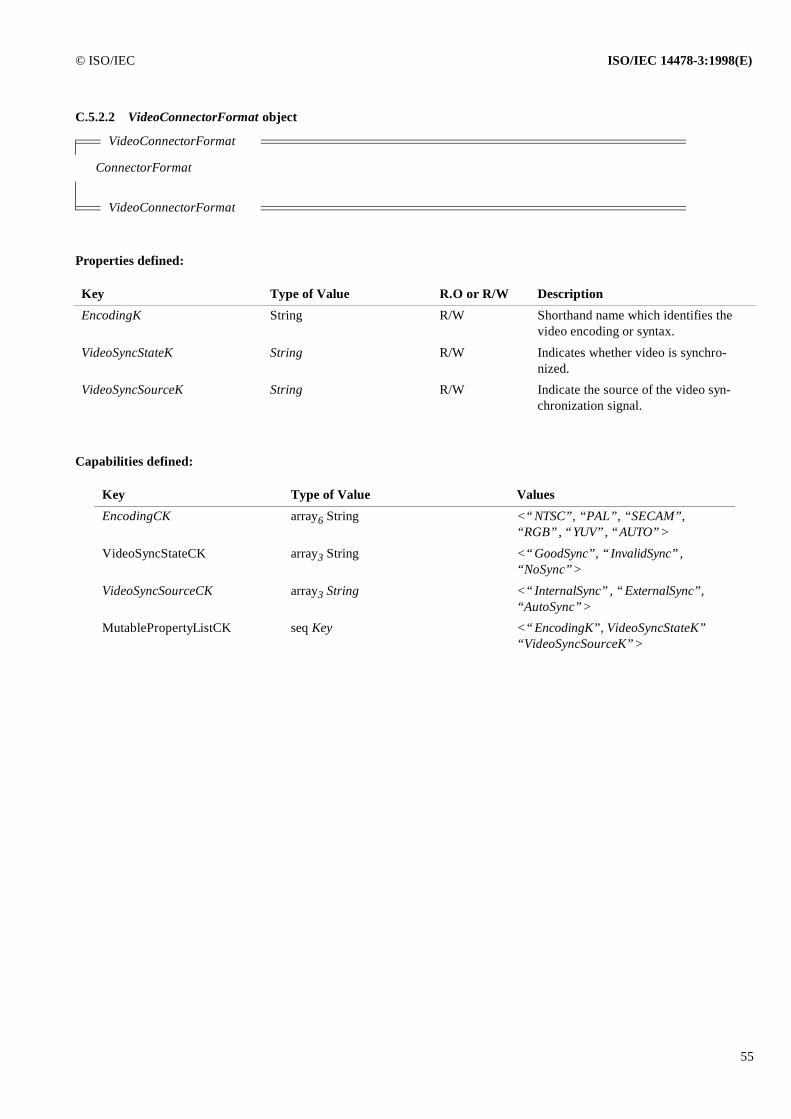
© ISO/IEC ISO/IEC 14478-3:1998(E)
55
C.5.2.2 VideoConnectorFormat object
Properties defined:
Capabilities defined:
VideoConnectorFormat
ConnectorFormat
VideoConnectorFormat
Key Type of Value R.O or R/W Description
EncodingK String R/W Shorthand name which identifies the video encoding or syntax.
VideoSyncStateK String R/W Indicates whether video is synchro-nized.
VideoSyncSourceK String R/W Indicate the source of the video syn-chronization signal.
Key Type of Value Values
EncodingCK array6 String <“NTSC”, “PAL”, “SECAM”, “RGB”, “YUV”, “AUTO”>
VideoSyncStateCK array3 String <“GoodSync”, “InvalidSync”,“NoSync”>
VideoSyncSourceCK array3 String <“InternalSync”, “ExternalSync”,“AutoSync”>
MutablePropertyListCK seq Key <“EncodingK”, VideoSyncStateK”“VideoSyncSourceK”>
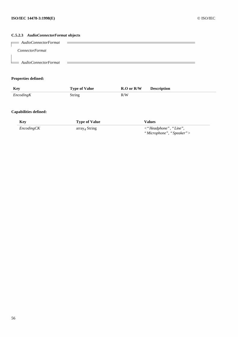
ISO/IEC 14478-3:1998(E) © ISO/IEC
56
C.5.2.3 AudioConnectorFormat objects
Properties defined:
Capabilities defined:
AudioConnectorFormat
ConnectorFormat
AudioConnectorFormat
Key Type of Value R.O or R/W Description
EncodingK String R/W
Key Type of Value Values
EncodingCK array4 String <“Headphone”, “Line”,“Microphone”, “Speaker”>
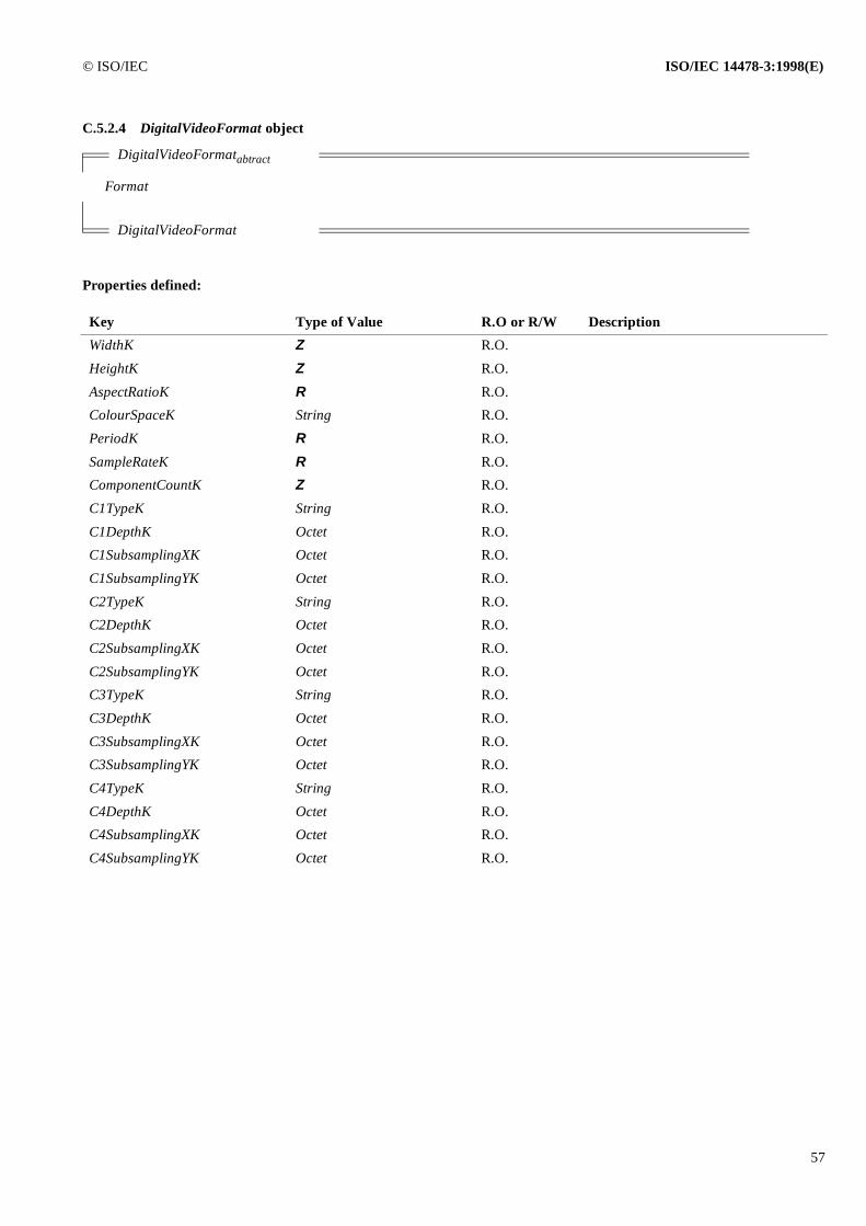
© ISO/IEC ISO/IEC 14478-3:1998(E)
57
C.5.2.4 DigitalVideoFormat object
Properties defined:
DigitalVideoFormatabtract
Format
DigitalVideoFormat
Key Type of Value R.O or R/W Description
WidthK Z R.O.
HeightK Z R.O.
AspectRatioK R R.O.
ColourSpaceK String R.O.
PeriodK R R.O.
SampleRateK R R.O.
ComponentCountK Z R.O.
C1TypeK String R.O.
C1DepthK Octet R.O.
C1SubsamplingXK Octet R.O.
C1SubsamplingYK Octet R.O.
C2TypeK String R.O.
C2DepthK Octet R.O.
C2SubsamplingXK Octet R.O.
C2SubsamplingYK Octet R.O.
C3TypeK String R.O.
C3DepthK Octet R.O.
C3SubsamplingXK Octet R.O.
C3SubsamplingYK Octet R.O.
C4TypeK String R.O.
C4DepthK Octet R.O.
C4SubsamplingXK Octet R.O.
C4SubsamplingYK Octet R.O.
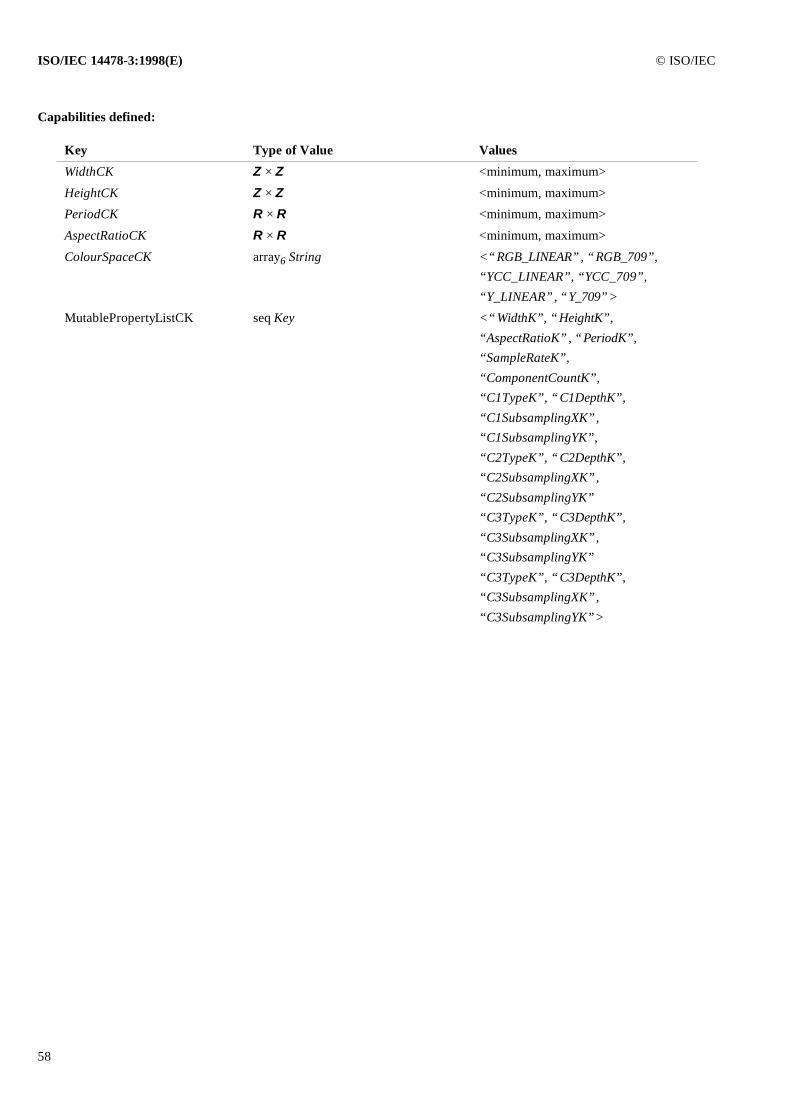
ISO/IEC 14478-3:1998(E) © ISO/IEC
58
Capabilities defined:
Key Type of Value Values
WidthCK Z × Z <minimum, maximum>
HeightCK Z × Z <minimum, maximum>
PeriodCK R × R <minimum, maximum>
AspectRatioCK R × R <minimum, maximum>
ColourSpaceCK array6 String <“RGB_LINEAR”, “RGB_709”,“YCC_LINEAR”, “YCC_709”,“Y_LINEAR”, “Y_709”>
MutablePropertyListCK seq Key <“WidthK”, “HeightK”,“AspectRatioK”, “PeriodK”,“SampleRateK”, “ComponentCountK”,“C1TypeK”, “C1DepthK”,“C1SubsamplingXK”,“C1SubsamplingYK”,“C2TypeK”, “C2DepthK”,“C2SubsamplingXK”,“C2SubsamplingYK”“C3TypeK”, “C3DepthK”,“C3SubsamplingXK”,“C3SubsamplingYK”“C3TypeK”, “C3DepthK”,“C3SubsamplingXK”,“C3SubsamplingYK”>
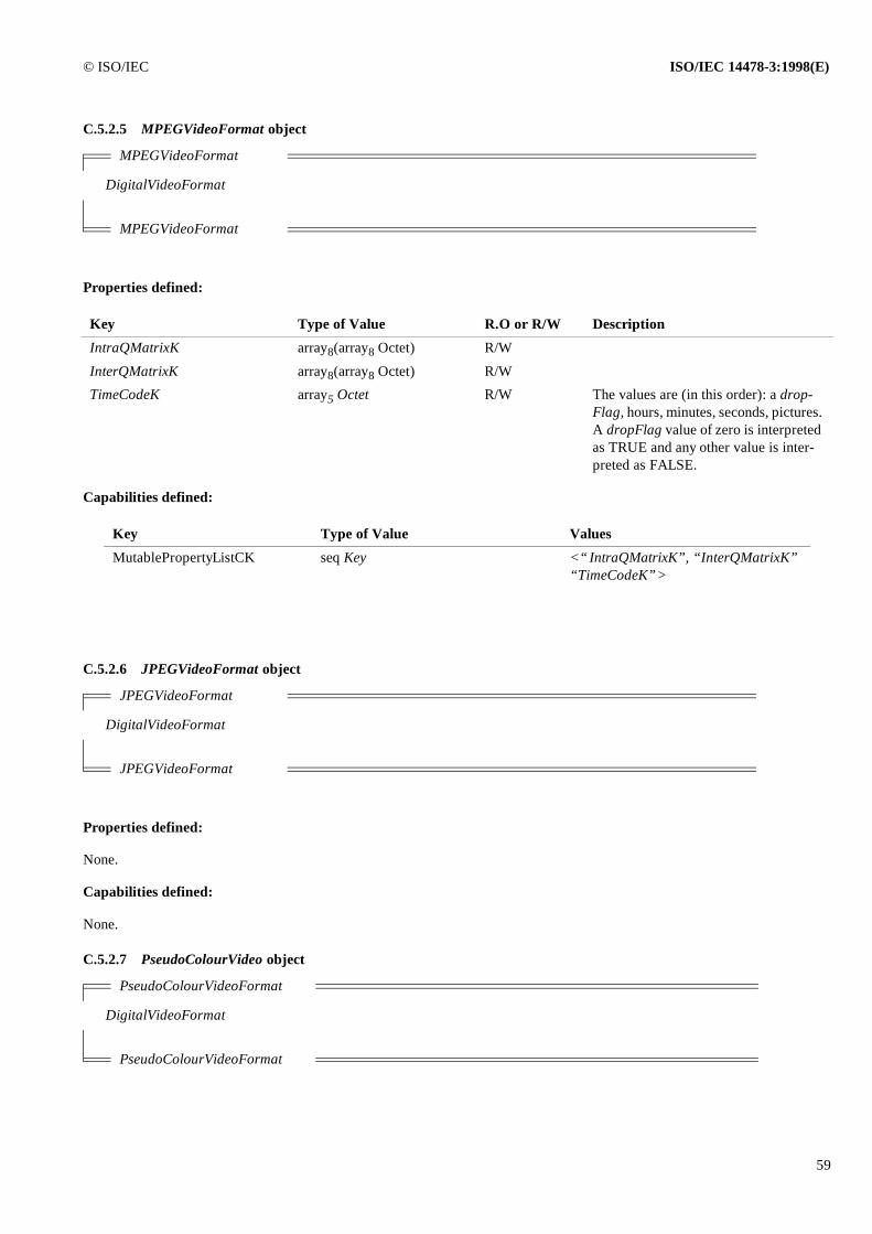
© ISO/IEC ISO/IEC 14478-3:1998(E)
59
C.5.2.5 MPEGVideoFormat object
Properties defined:
Capabilities defined:
C.5.2.6 JPEGVideoFormat object
Properties defined:
None.
Capabilities defined:
None.
C.5.2.7 PseudoColourVideo object
MPEGVideoFormat
DigitalVideoFormat
MPEGVideoFormat
Key Type of Value R.O or R/W Description
IntraQMatrixK array8(array8 Octet) R/W
InterQMatrixK array8(array8 Octet) R/W
TimeCodeK array5 Octet R/W The values are (in this order): a drop-Flag, hours, minutes, seconds, pictures. A dropFlag value of zero is interpreted as TRUE and any other value is inter-preted as FALSE.
Key Type of Value Values
MutablePropertyListCK seq Key <“IntraQMatrixK”, “InterQMatrixK”“TimeCodeK”>
JPEGVideoFormat
DigitalVideoFormat
JPEGVideoFormat
PseudoColourVideoFormat
DigitalVideoFormat
PseudoColourVideoFormat
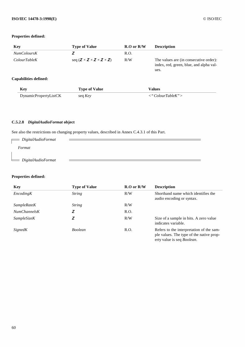
ISO/IEC 14478-3:1998(E) © ISO/IEC
60
Properties defined:
Capabilities defined:
C.5.2.8 DigitalAudioFormat object
See also the restrictions on changing property values, described in Annex C.4.3.1 of this Part.
Properties defined:
Key Type of Value R.O or R/W Description
NumColoursK Z R.O.
ColourTableK seq (Z × Z × Z × Z × Z) R/W The values are (in consecutive order): index, red, green, blue, and alpha val-ues.
Key Type of Value Values
DynamicPropertyListCK seq Key <“ColourTableK”>
DigitalAudioFormat
Format
DigitalAudioFormat
Key Type of Value R.O or R/W Description
EncodingK String R/W Shorthand name which identifies the audio encoding or syntax.
SampleRateK String R/W
NumChannelsK Z R.O.
SampleSizeK Z R/W Size of a sample in bits. A zero value indicates variable.
SignedK Boolean R.O. Refers to the interpretation of the sam-ple values. The type of the native prop-erty value is seq Boolean.
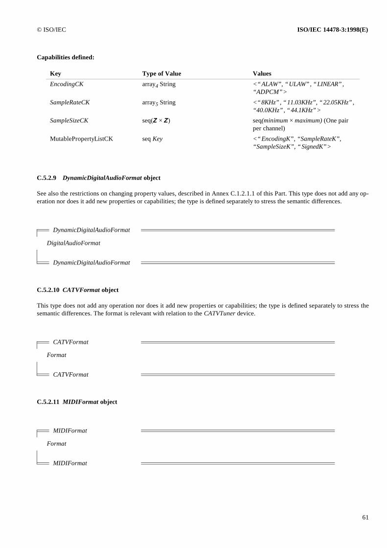
© ISO/IEC ISO/IEC 14478-3:1998(E)
61
Capabilities defined:
C.5.2.9 DynamicDigitalAudioFormat object
See also the restrictions on changing property values, described in Annex C.1.2.1.1 of this Part. This type does not add any op-eration nor does it add new properties or capabilities; the type is defined separately to stress the semantic differences.
C.5.2.10 CATVFormat object
This type does not add any operation nor does it add new properties or capabilities; the type is defined separately to stress thesemantic differences. The format is relevant with relation to the CATVTuner device.
C.5.2.11 MIDIFormat object
Key Type of Value Values
EncodingCK array4 String <“ALAW”, “ULAW”, “LINEAR”, “ADPCM”>
SampleRateCK array5 String <“8KHz”, “11.03KHz”, “22.05KHz”, “40.0KHz”, “44.1KHz”>
SampleSizeCK seq(Z × Z) seq(minimum × maximum) (One pair per channel)
MutablePropertyListCK seq Key <“EncodingK”, “SampleRateK”,“SampleSizeK”, “SignedK”>
DynamicDigitalAudioFormat
DigitalAudioFormat
DynamicDigitalAudioFormat
CATVFormat
Format
CATVFormat
MIDIFormat
Format
MIDIFormat
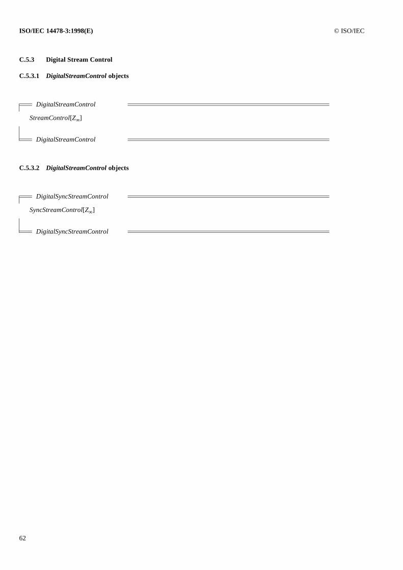
ISO/IEC 14478-3:1998(E) © ISO/IEC
62
C.5.3 Digital Stream Control
C.5.3.1 DigitalStreamControl objects
C.5.3.2 DigitalStreamControl objects
DigitalStreamControl
StreamControl[Z∞]
DigitalStreamControl
DigitalSyncStreamControl
SyncStreamControl[Z∞]
DigitalSyncStreamControl
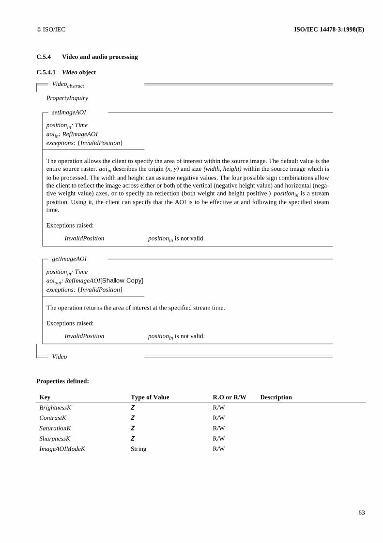
© ISO/IEC ISO/IEC 14478-3:1998(E)
63
C.5.4 Video and audio processing
C.5.4.1 Video object
Properties defined:
Videoabstract
PropertyInquiry
setImageAOI
positionin: Timeaoiin: RefImageAOIexceptions: {InvalidPosition}
The operation allows the client to specify the area of interest within the source image. The default value is theentire source raster. aoiin describes the origin (x, y) and size (width, height) within the source image which isto be processed. The width and height can assume negative values. The four possible sign combinations allowthe client to reflect the image across either or both of the vertical (negative height value) and horizontal (nega-tive weight value) axes, or to specify no reflection (both weight and height positive.) positionin is a streamposition. Using it, the client can specify that the AOI is to be effective at and following the specified steamtime.
Exceptions raised:
InvalidPosition positionin is not valid.
getImageAOI
positionin: Timeaoiout: RefImageAOI[Shallow Copy]exceptions: {InvalidPosition}
The operation returns the area of interest at the specified stream time.
Exceptions raised:
InvalidPosition positionin is not valid.
Video
Key Type of Value R.O or R/W Description
BrightnessK Z R/W
ContrastK Z R/W
SaturationK Z R/W
SharpnessK Z R/W
ImageAOIModeK String R/W
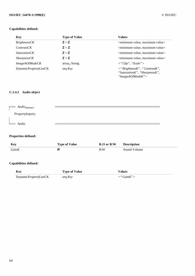
ISO/IEC 14478-3:1998(E) © ISO/IEC
64
Capabilities defined:
C.5.4.2 Audio object
Properties defined:
Capabilities defined:
Key Type of Value Values
BrightnessCK Z × Z <minimum value, maximum value>
ContrastCK Z × Z <minimum value, maximum value>
SaturationCK Z × Z <minimum value, maximum value>
SharpnessCK Z × Z <minimum value, maximum value>
ImageAOIModeCK array2 String <“Clip”, “Scale”>
DynamicPropertyListCK seq Key <“BrightnessK”, “ContrastK”,“SaturationK”, “SharpnessK”,“ImageAOIModeK”>
Audioabstract
PropertyInquiry
Audio
Key Type of Value R.O or R/W Description
GainK R R/W Sound Volume
Key Type of Value Values
DynamicPropertyListCK seq Key <“GainK”>
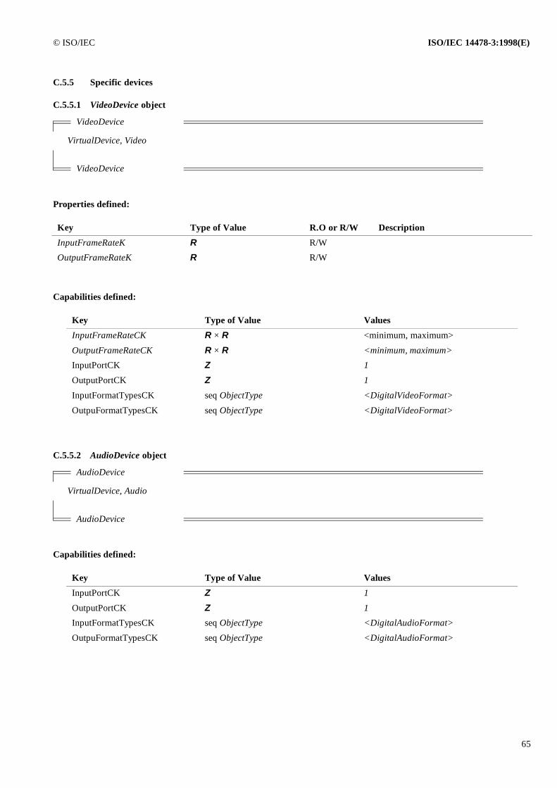
© ISO/IEC ISO/IEC 14478-3:1998(E)
65
C.5.5 Specific devices
C.5.5.1 VideoDevice object
Properties defined:
Capabilities defined:
C.5.5.2 AudioDevice object
Capabilities defined:
VideoDevice
VirtualDevice, Video
VideoDevice
Key Type of Value R.O or R/W Description
InputFrameRateK R R/W
OutputFrameRateK R R/W
Key Type of Value Values
InputFrameRateCK R × R <minimum, maximum>
OutputFrameRateCK R × R <minimum, maximum>
InputPortCK Z 1
OutputPortCK Z 1
InputFormatTypesCK seq ObjectType <DigitalVideoFormat>
OutpuFormatTypesCK seq ObjectType <DigitalVideoFormat>
AudioDevice
VirtualDevice, Audio
AudioDevice
Key Type of Value Values
InputPortCK Z 1
OutputPortCK Z 1
InputFormatTypesCK seq ObjectType <DigitalAudioFormat>
OutpuFormatTypesCK seq ObjectType <DigitalAudioFormat>
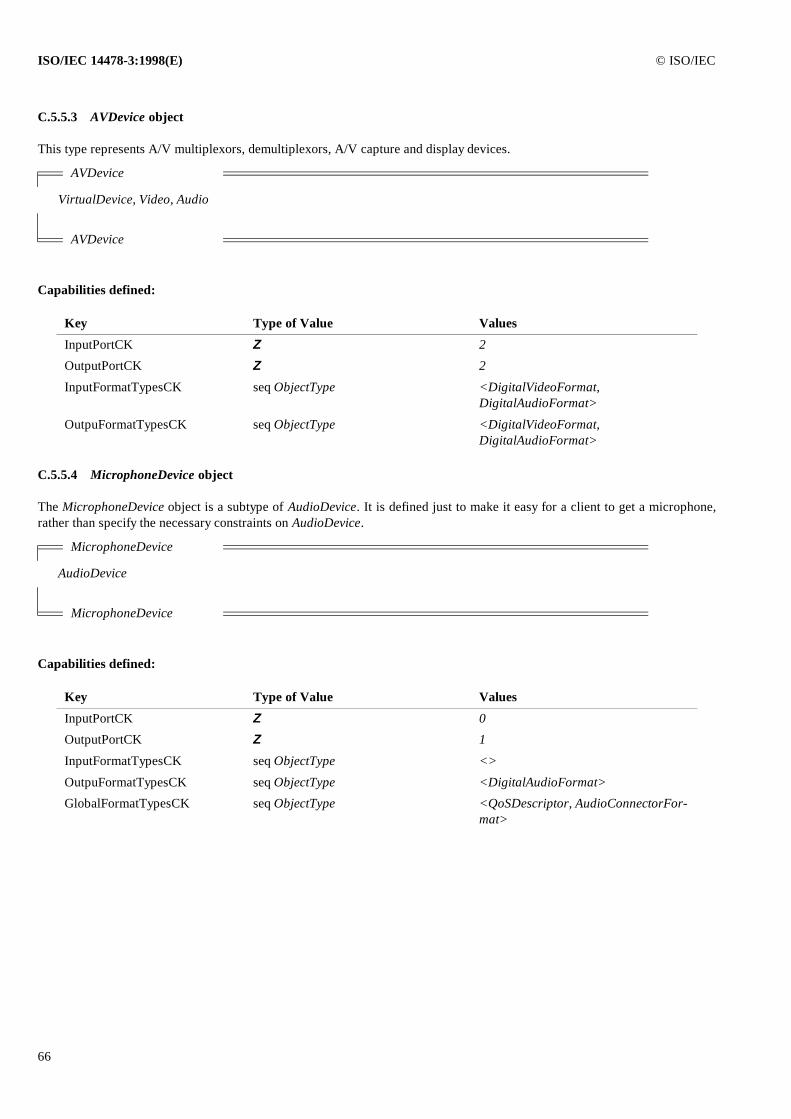
ISO/IEC 14478-3:1998(E) © ISO/IEC
66
C.5.5.3 AVDevice object
This type represents A/V multiplexors, demultiplexors, A/V capture and display devices.
Capabilities defined:
C.5.5.4 MicrophoneDevice object
The MicrophoneDevice object is a subtype of AudioDevice. It is defined just to make it easy for a client to get a microphone,rather than specify the necessary constraints on AudioDevice.
Capabilities defined:
AVDevice
VirtualDevice, Video, Audio
AVDevice
Key Type of Value Values
InputPortCK Z 2
OutputPortCK Z 2
InputFormatTypesCK seq ObjectType <DigitalVideoFormat,DigitalAudioFormat>
OutpuFormatTypesCK seq ObjectType <DigitalVideoFormat,DigitalAudioFormat>
MicrophoneDevice
AudioDevice
MicrophoneDevice
Key Type of Value Values
InputPortCK Z 0
OutputPortCK Z 1
InputFormatTypesCK seq ObjectType <>
OutpuFormatTypesCK seq ObjectType <DigitalAudioFormat>
GlobalFormatTypesCK seq ObjectType <QoSDescriptor, AudioConnectorFor-mat>
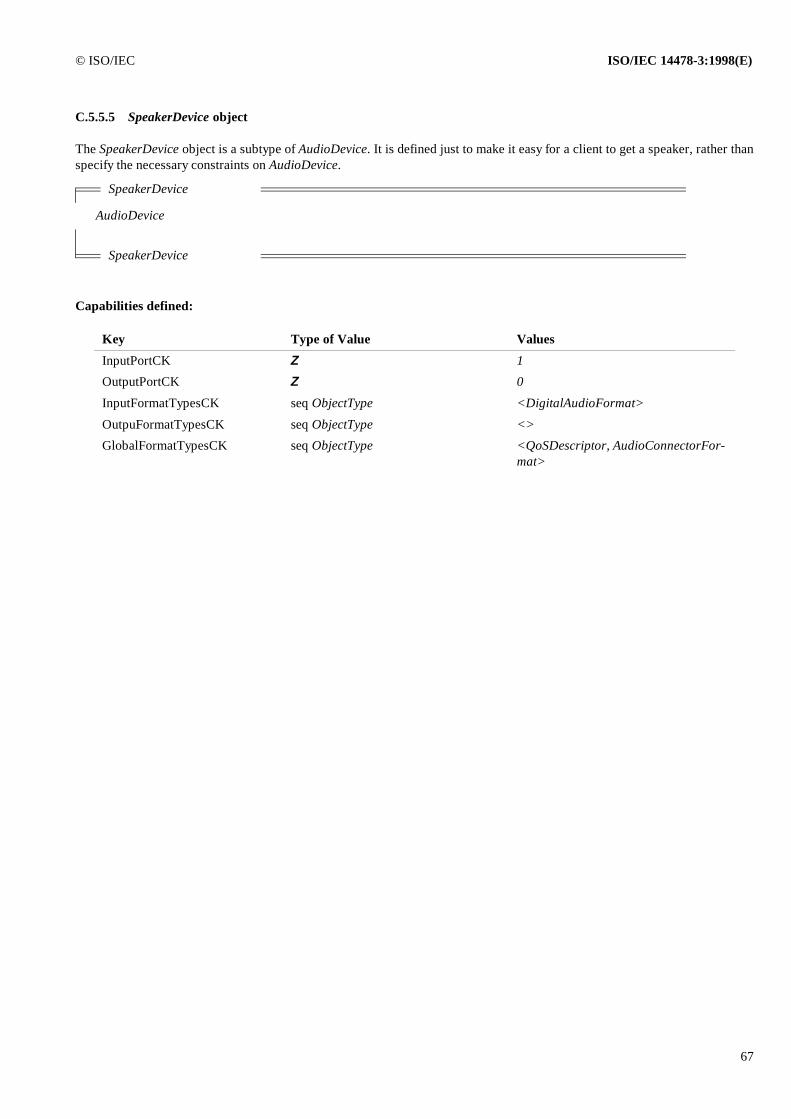
© ISO/IEC ISO/IEC 14478-3:1998(E)
67
C.5.5.5 SpeakerDevice object
The SpeakerDevice object is a subtype of AudioDevice. It is defined just to make it easy for a client to get a speaker, rather thanspecify the necessary constraints on AudioDevice.
Capabilities defined:
SpeakerDevice
AudioDevice
SpeakerDevice
Key Type of Value Values
InputPortCK Z 1
OutputPortCK Z 0
InputFormatTypesCK seq ObjectType <DigitalAudioFormat>
OutpuFormatTypesCK seq ObjectType <>
GlobalFormatTypesCK seq ObjectType <QoSDescriptor, AudioConnectorFor-mat>
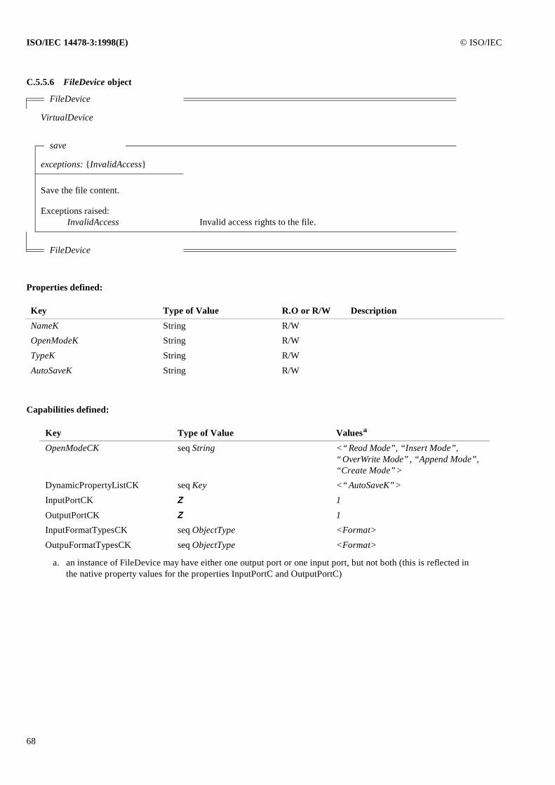
ISO/IEC 14478-3:1998(E) © ISO/IEC
68
C.5.5.6 FileDevice object
Properties defined:
Capabilities defined:
FileDevice
VirtualDevice
save
exceptions: {InvalidAccess}
Save the file content.
Exceptions raised:InvalidAccess Invalid access rights to the file.
FileDevice
Key Type of Value R.O or R/W Description
NameK String R/W
OpenModeK String R/W
TypeK String R/W
AutoSaveK String R/W
Key Type of Value Valuesa
a. an instance of FileDevice may have either one output port or one input port, but not both (this is reflected in the native property values for the properties InputPortC and OutputPortC)
OpenModeCK seq String <“Read Mode”, “Insert Mode”, “OverWrite Mode”, “Append Mode”, “Create Mode”>
DynamicPropertyListCK seq Key <“AutoSaveK”>
InputPortCK Z 1
OutputPortCK Z 1
InputFormatTypesCK seq ObjectType <Format>
OutpuFormatTypesCK seq ObjectType <Format>
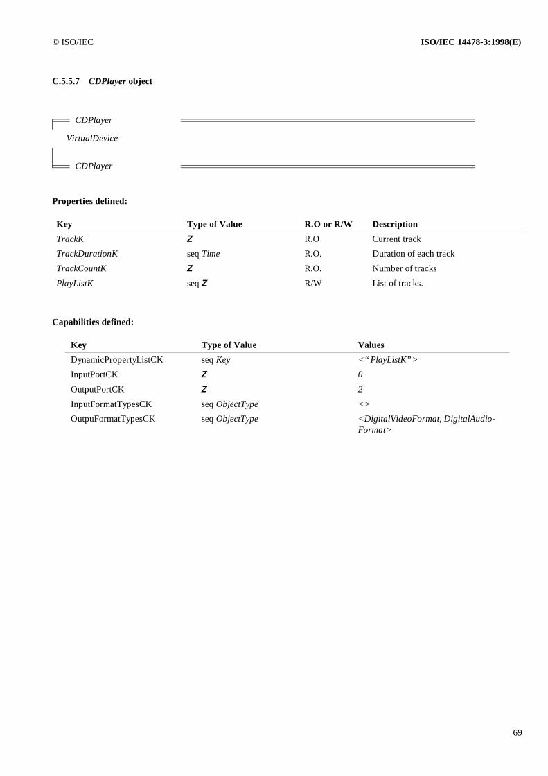
© ISO/IEC ISO/IEC 14478-3:1998(E)
69
C.5.5.7 CDPlayer object
Properties defined:
Capabilities defined:
CDPlayer
VirtualDevice
CDPlayer
Key Type of Value R.O or R/W Description
TrackK Z R.O Current track
TrackDurationK seq Time R.O. Duration of each track
TrackCountK Z R.O. Number of tracks
PlayListK seq Z R/W List of tracks.
Key Type of Value Values
DynamicPropertyListCK seq Key <“PlayListK”>
InputPortCK Z 0
OutputPortCK Z 2
InputFormatTypesCK seq ObjectType <>
OutpuFormatTypesCK seq ObjectType <DigitalVideoFormat, DigitalAudio-Format>
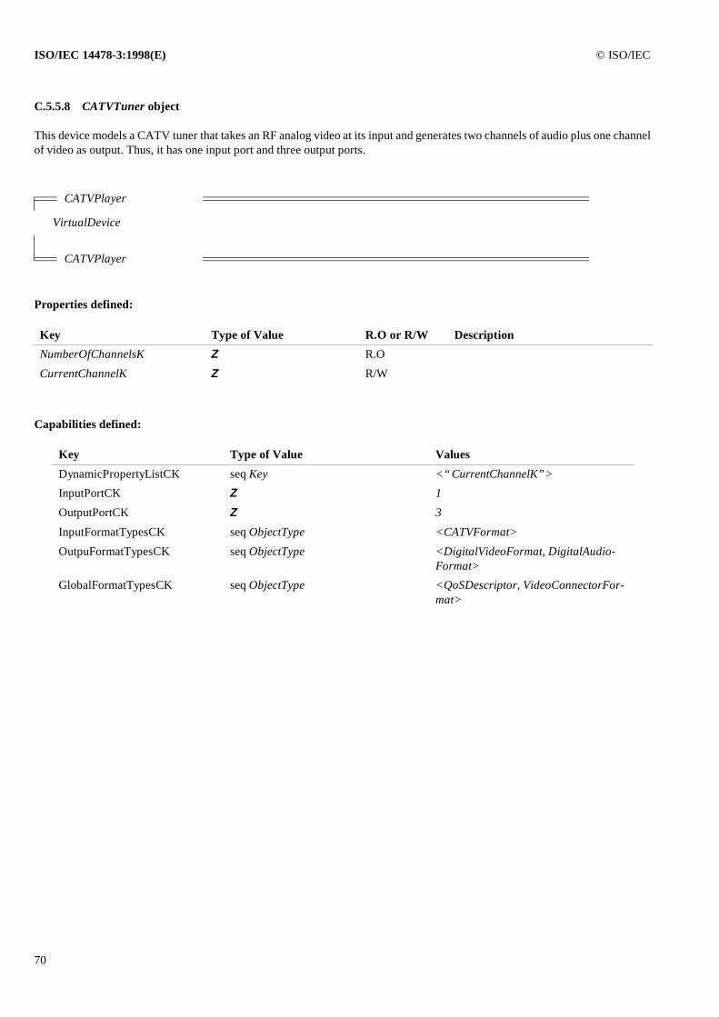
ISO/IEC 14478-3:1998(E) © ISO/IEC
70
C.5.5.8 CATVTuner object
This device models a CATV tuner that takes an RF analog video at its input and generates two channels of audio plus one channelof video as output. Thus, it has one input port and three output ports.
Properties defined:
Capabilities defined:
CATVPlayer
VirtualDevice
CATVPlayer
Key Type of Value R.O or R/W Description
NumberOfChannelsK Z R.O
CurrentChannelK Z R/W
Key Type of Value Values
DynamicPropertyListCK seq Key <“CurrentChannelK”>
InputPortCK Z 1
OutputPortCK Z 3
InputFormatTypesCK seq ObjectType <CATVFormat>
OutpuFormatTypesCK seq ObjectType <DigitalVideoFormat, DigitalAudio-Format>
GlobalFormatTypesCK seq ObjectType <QoSDescriptor, VideoConnectorFor-mat>
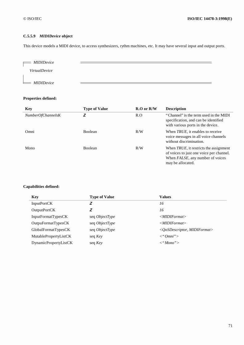
© ISO/IEC ISO/IEC 14478-3:1998(E)
71
C.5.5.9 MIDIDevice object
This device models a MIDI device, to access synthesizers, rythm machines, etc. It may have several input and output ports.
Properties defined:
Capabilities defined:
MIDIDevice
VirtualDevice
MIDIDevice
Key Type of Value R.O or R/W Description
NumberOfChannelsK Z R.O “Channel” is the term used in the MIDI specification, and can be identified with various ports in the device.
Omni Boolean R/W When TRUE, it enables to receive voice messages in all voice channels without discrimination.
Mono Boolean R/W When TRUE, it restricts the assignment of voices to just one voice per channel. When FALSE, any number of voices may be allocated.
Key Type of Value Values
InputPortCK Z 16
OutputPortCK Z 16
InputFormatTypesCK seq ObjectType <MIDIFormat>
OutpuFormatTypesCK seq ObjectType <MIDIFormat>
GlobalFormatTypesCK seq ObjectType <QoSDescriptor, MIDIFormat>
MutablePropertyListCK seq Key <“Omni”>
DynamicPropertyListCK seq Key <“Mono”>
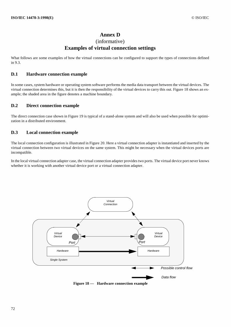
ISO/IEC 14478-3:1998(E) © ISO/IEC
72
Annex D (informative)
Examples of virtual connection settings
What follows are some examples of how the virtual connections can be configured to support the types of connections definedin 9.3.
D.1 Hardware connection example
In some cases, system hardware or operating system software performs the media data transport between the virtual devices. Thevirtual connection determines this, but it is then the responsibility of the virtual devices to carry this out. Figure 18 shows an ex-ample; the shaded area in the figure denotes a machine boundary.
D.2 Direct connection example
The direct connection case shown in Figure 19 is typical of a stand-alone system and will also be used when possible for optimi-zation in a distributed environment.
D.3 Local connection example
The local connection configuration is illustrated in Figure 20. Here a virtual connection adapter is instantiated and inserted by thevirtual connection between two virtual devices on the same system. This might be necessary when the virtual devices ports areincompatible.
In the local virtual connection adapter case, the virtual connection adapter provides two ports. The virtual device port never knowswhether it is working with another virtual device port or a virtual connection adapter.
VirtualConnection
VirtualDevice
Port
VirtualDevice
Port
Hardware Hardware
Data flow
Possible control flow
Single System
Figure 18 — Hardware connection example
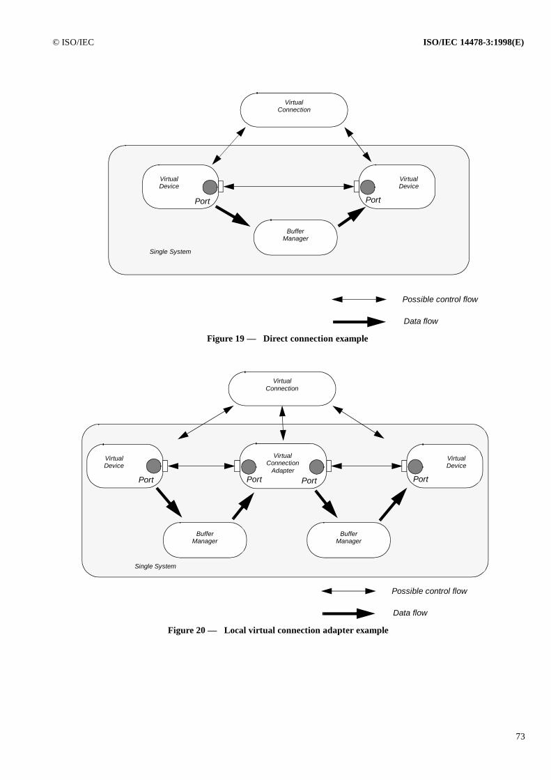
© ISO/IEC ISO/IEC 14478-3:1998(E)
73
VirtualConnection
VirtualDevice
Port
VirtualDevice
Port
Single System
Data flow
Possible control flow
Figure 19 — Direct connection example
BufferManager
Figure 20 — Local virtual connection adapter example
VirtualConnection
VirtualDevice
Port
VirtualDevice
Port
Single System
Data flow
Possible control flow
BufferManager
BufferManager
VirtualConnection
AdapterPort Port
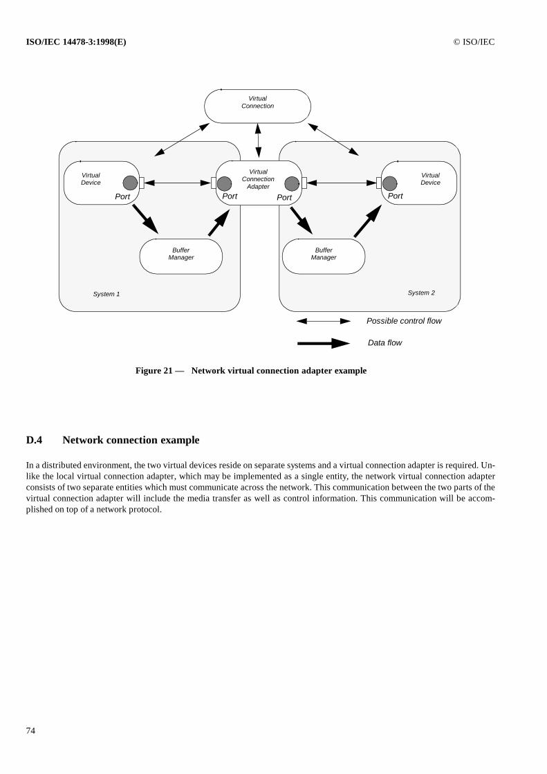
ISO/IEC 14478-3:1998(E) © ISO/IEC
74
D.4 Network connection example
In a distributed environment, the two virtual devices reside on separate systems and a virtual connection adapter is required. Un-like the local virtual connection adapter, which may be implemented as a single entity, the network virtual connection adapterconsists of two separate entities which must communicate across the network. This communication between the two parts of thevirtual connection adapter will include the media transfer as well as control information. This communication will be accom-plished on top of a network protocol.
Figure 21 — Network virtual connection adapter example
VirtualConnection
VirtualDevice
Port
VirtualDevice
Port
System 1
Data flow
Possible control flow
BufferManager
BufferManager
VirtualConnection
Adapter
Port Port
System 2