prelude 24 max - armstrongceilings.com · ansi/asme b18.2.2, grade 2, 11/16" width,...
TRANSCRIPT

PRELUDE® 24 MAXTM
SUSPENSION SYSTEM TECHNICAL GUIDE
DATA CENTRE CEILING SOLUTIONS

TECHNICAL GUIDEThe Prelude® 24 MaxTM suspension system for data centre applications is a pre-engineered ceiling suspension system designed for improved air flow management, load carrying capacity, and adaptability in data centres of all sizes.
The Prelude 24 Max suspension system uses M10 threaded rod support and reconfigurable load connector clips to support cable trays, bus bars, hot aisle containment, and other components to provide maximum load carrying capacity and flexibility, while eliminating the need for a separate strut channel suspension system.
Code Compliance You Can Trust
Suspension system meets:
• EN 13964
• ASTM E580
• ICC-ES AC156
Seismic D, E, F configurations available.
Prelude 24 Max24 mm Suspension System
– Supports load from the face utilising M10 threaded rod and integrated hanging clips.
– Allows for flexible and reconfigurable overhead cable trays, electrical distribution and hot aisle containment to meet client needs without a separate strut channel system.
Key Selection Attributes

TABLE OF CONTENTS
2 Code Compliance
2 Performance
4 How the System Works
5 Suspension System Components
6 Recommended Ceiling Panels
7 Installation Overview and Hardware
8 Installation/Layout Overview and Seismic Data
9 Point Load Data – Centre and Mid Point
10 Point Load Data – Single and Dual Point Connection and Seismic Data
PREL
UDE®
24
MAX
TM
3Please contact Armstrong Technical Sales for further details.
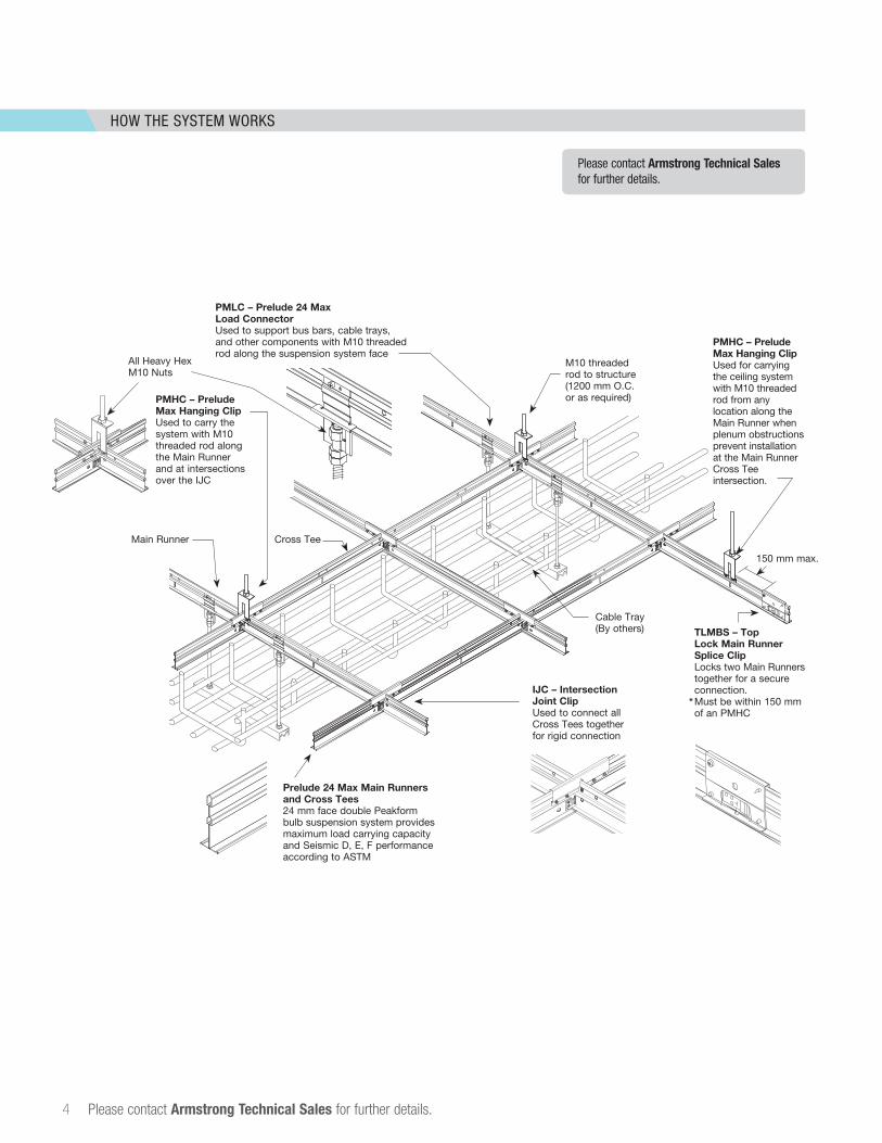
HOW THE SYSTEM WORKS
4 Please contact Armstrong Technical Sales for further details.
Please contact Armstrong Technical Salesfor further details.
PMLC – Prelude 24 Max Load Connector Used to support bus bars, cable trays, and other components with M10 threaded rod along the suspension system face
PMHC – Prelude Max Hanging Clip Used to carry the system with M10 threaded rod along the Main Runner and at intersections over the IJC
PMHC – Prelude Max Hanging Clip Used for carrying the ceiling system with M10 threaded rod from any location along the Main Runner when plenum obstructions prevent installation at the Main Runner Cross Tee intersection.
Prelude 24 Max Main Runners and Cross Tees 24 mm face double Peakform bulb suspension system provides maximum load carrying capacity and Seismic D, E, F performance according to ASTM
M10 threaded rod to structure (1200 mm O.C. or as required)
Main Runner
IJC – Intersection Joint Clip Used to connect all Cross Tees together for rigid connection
IHC – Intersection Hanging Clip
SHC – Supplemental Hanging Clip
IHC – Intersection Hanging Clip
3/8–16"Heavy HexLocknutIncluded with IHC; do not substitute.
3/8–16" Threaded Rod
3/8–16" Heavy Hex NutIncluded with IHC; do not substitute.
IHC Clip
Imperial: 3/8" Washer, 1/8" Thickness, 7/8" Width,
Steel with Black Oxide �nish,Grade 1010
(MSC Item #94491586)
M5 x 6mm, 0.8mmPan Head
Machine Screws
* Threadlocker Adhesive Required
3/8–16" Threaded Rod
3/8–16" Heavy Hex NutIncluded with SHC; do not substitute.
3/8–16" Heavy Hex LocknutIncluded with SHC; do not substitute.
SHC Clip
SHC – Supplemental Hanging Clip Installation
PMLC – Load Connector Clip
Heavy Hex LocknutIncluded with PMLC – do not substitute.
1
M10 Heavy Hex NutsIncluded with PMLC – do not substitute.
PMLC Clip
#8 x 1/2" longTruss Head
Sharp Point Screw
M10Threaded Rod
Load Connector Clip Installation
IJC – Intersection Joint Clip
2
3
IHC – Intersection Hanging Clip Installation
Make sure thatthe head of the
rivet goes throughthe XL clip.
The expandedportion of the rivet
needs to expandon the IHC clip.
Blind Steel Pop Rivets1/8" Dia. x .337" Long
.126" – .186" Grip RangeShear Strength: 260 lbs.
Included with SHC; do not substitute.
(4) #8 x 1/2" LongSharp Point Truss Head Screws
Top Lock Main Beam
Splice Clip
TLMBS – Top Lock Main Beam Splice Clip
Top Lock Main BeamSplice Clip Installation
on two Prelude XL MaxMain Beams
Cross Tee
Cable Tray (By others)
All Heavy Hex M10 Nuts
150 mm max.
TLMBS – Top Lock Main Runner Splice Clip Locks two Main Runners together for a secure connection. Must be within 150 mm of an PMHC
*
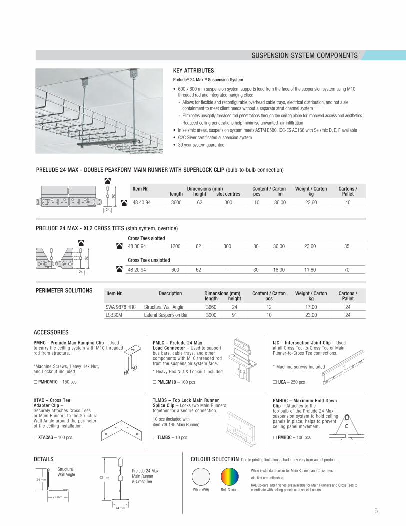
SUSPENSION SYSTEM COMPONENTS
KEY ATTRIBUTESPrelude® 24 MaxTM Suspension System
• 600 x 600 mm suspension system supports load from the face of the suspension system using M10 threaded rod and integrated hanging clips:
- Allows for flexible and reconfigurable overhead cable trays, electrical distribution, and hot aisle containment to meet client needs without a separate strut channel system
- Eliminates unsightly threaded rod penetrations through the ceiling plane for improved access and aesthetics
- Reduced ceiling penetrations help minimise unwanted air infiltration
• In seismic areas, suspension system meets ASTM E580, ICC-ES AC156 with Seismic D, E, F available
• C2C Silver certificated suspension system
• 30 year system guarantee
DETAILS COLOUR SELECTION Due to printing limitations, shade may vary from actual product.
Prelude 24 Max Main Runner & Cross Tee
StructuralWall Angle
1-11/16"(43mm)
5/16"(8mm)
15/16"(24mm)
1/4"(6mm)
15/16"(24mm)
15/16"(24mm)
2"(51mm)
5/16"(8mm)
1/4"(6mm)
1-1/2"(38mm)
7/8"(22mm)
7/8"(22mm)
62 mm
24 mm
22 mm
24 mm
White (WH)
White is standard colour for Main Runners and Cross Tees.
All clips are unfinished.
RAL Colours and finishes are available for Main Runners and Cross Tees to coordinate with ceiling panels as a special option.RAL Colours
PMHDC – Maximum Hold Down Clip – Attaches to the top bulb of the Prelude 24 Max suspension system to hold ceiling panels in place; helps to prevent ceiling panel movement.
PMHC - Prelude Max Hanging Clip – Used to carry the ceiling system with M10 threaded rod from structure.
TLMBS – Top Lock Main Runner Splice Clip – Locks two Main Runners together for a secure connection.
10 pcs (included with item 730145 Main Runner)
PMHCM10 – 150 pcs PMLCM10 – 100 pcs
PMHDC – 100 pcs
ACCESSORIES
TLMBS – 10 pcs
IJC – Intersection Joint Clip – Used at all Cross Tee-to-Cross Tee or Main Runner-to-Cross Tee connections.
IJCA – 250 pcs
XTAC – Cross Tee Adapter Clip – Securely attaches Cross Tees or Main Runners to the Structural Wall Angle around the perimeter of the ceiling installation.
XTACAG – 100 pcs
* Heavy Hex Nut & Locknut included* Machine screws included*Machine Screws, Heavy Hex Nut,
and Locknut included
PMLC – Prelude 24 Max Load Connector – Used to support bus bars, cable trays, and other components with M10 threaded rod from the suspension system face.
PRELUDE 24 MAX - DOUBLE PEAKFORM MAIN RUNNER WITH SUPERLOCK CLIP (bulb-to-bulb connection)
PRELUDE 24 MAX - XL2 CROSS TEES (stab system, override)
PERIMETER SOLUTIONS
Cross Tees slotted
48 30 94 1200 62 300 30 36,00 23,60 35
Cross Tees unslotted
48 20 94 600 62 - 30 18,00 11,80 70
Item Nr. Dimensions (mm) Content / Carton Weight / Carton Cartons /length height slot centres pcs lm kg Pallet
48 40 94 3600 62 300 10 36,00 23,60 40
Item Nr. Description Dimensions (mm) Content / Carton Weight / Carton Cartons /length height pcs kg Pallet
SWA 9878 HRC Structural Wall Angle 3660 24 12 17,00 24
LSB30M Lateral Suspension Bar 3000 91 10 23,00 24
24
62
24
62
5
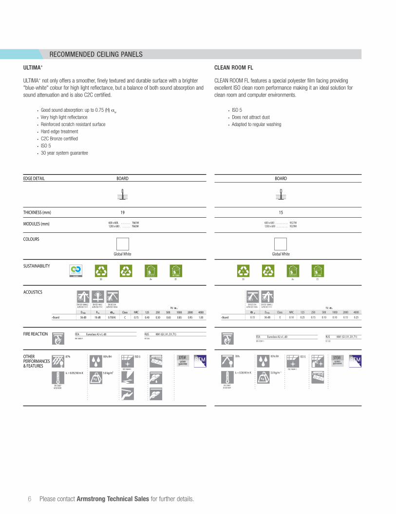
RECOMMENDED CEILING PANELS
6 Please contact Armstrong Technical Sales for further details.
ULTIMA+
ULTIMA+ not only offers a smoother, finely textured and durable surface with a brighter "blue-white" colour for high light reflectance, but a balance of both sound absorption and sound attenuation and is also C2C certified.
• Good sound absorption: up to 0.75 (H) aw
• Very high light reflectance• Reinforced scratch resistant surface• Hard edge treatment• C2C Bronze certified• ISO 5• 30 year system guarantee
EN 12667 & ISO 8301
= 0.06 W/m K 5.0 kg/m 2
95% RH78%
Global White Global White
600 x 600 . . . . . . . . . . . 9527M1200 x 600 . . . . . . . . . . 9529M
Hz P
W Dnfw Class NRC 125 250 500 1000 2000 4000
0.15 36 dB E 0.10 0.25 0.15 0.10 0.10 0.15 0.25
EN ISO 10848-2 & EN ISO 717-1
EN ISO 354 & EN ISO 11654
ISO 14644-1
ISO 5
EEA Euroclass A2-s1, d0EN 13501-1
RUS KM1 (G1, V1, D1, T1) FZ 123
A+ E139
%
30 YEARsystem
guarantee
BOARD BOARD
COLOURS
ACOUSTICS
FIRE REACTION
OTHERPERFORMANCES& FEATURES
EDGE DETAIL
THICKNESS (mm) 19 15
SUSTAINABILITY
A+ E1
EN ISO 354 & EN ISO 11654
EN ISO 10848-2 & EN ISO 717-1
EN ISO 140-3 & EN ISO 717-1 Hz P
Dnfw R w W Class NRC 125 250 500 1000 2000 4000
• Board Board36 dB 18 dB 0.70(H) C 0.75 0.40 0.50 0.65 0.85 0.95 1.00
RUS KM1 (G1, V1, D1, T1) FZ 123
EEA Euroclass A2-s1, d0EN 13501-1
EN 12667 & ISO 8301
= 0.052 W/m K 5.0 kg/m²
95% RH
ISO 14644-1
ISO 587%
600 x 600 . . . . . . . . 7661M 1200 x 600 . . . . . . . 7663MMODULES (mm)
50
%
30 YEARsystem
guarantee
•
CLEAN ROOM FL
CLEAN ROOM FL features a special polyester film facing providing excellent ISO clean room performance making it an ideal solution for clean room and computer environments.
• ISO 5• Does not attract dust• Adapted to regular washing
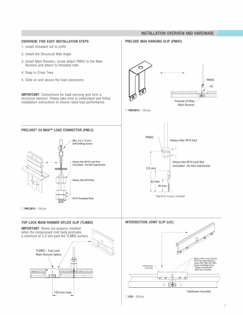
INSTALLATION OVERVIEW AND HARDWARE
7
IntersectionJoint Clip
Metric: M5 x 6 mm, 0.8 mm Pitch Pan Head Machine Screw DIN 7985; ISO 7045,Grade 4.8 Phillips Drive* Apply Threadlocker Blue 242 or similiar
IJCA – 250 pcs
INTERSECTION JOINT CLIP (IJC)TOP LOCK MAIN RUNNER SPLICE CLIP (TLMBS)
Min. 4.2 x 13 mmSelf Drilling Screw
M10 Threaded Rod
Heavy Hex M10 Lock Nut(Included - Do Not Substitute)
Heavy Hex M10 Nut
Imperial: Blind Steel Pop Rivets 1/8" Dia. x .337" Long.126" – .186" Grip RangeShear Strength: 260 lbs. IFI 114 Grade 30Size Code 43(MSC Item #76811066)
Imperial: 3/8-16 Heavy Hex Locknuts Grade 2, 11/16" Width, 35/64" Height (MSC Item #52592839)
Imperial: 3/8-16 Heavy Hex Nuts ANSI/ASME B18.2.2, Grade 2, 11/16" Width, 23/64" Height (MSC Item #87921425)
Imperial: 3/8" Threaded Rod Low-strength Steel
PMLC – Prelude XL Max Load ConnectorIHC – Intersection Hanging Clip
IJC - Intersection Joint Clip
Supplemental Hanging Clip (SHC)
Main Beam/4' Cross Tee
#8 x 1/2" L Sharp Point Truss Head Screws: Quantity 3
2'/4' Cross Tee
Imperial: 3/8-16 Heavy Hex Locknuts Grade 2, 11/16" Width, 35/64" Height (MSC Item #52592839)
Imperial: 3/8-16 Heavy Hex Nuts ANSI/ASME B18.2.2, Grade 2, 11/16" Width, 23/64" Height (MSC Item #87921425)
Imperial: 3/8" Threaded Rod Low-strength Steel
Metric: M5 x 6mm, 0.8mm Pitch Pan Head Machine Screw DIN 7985; ISO 7045,Grade 4.8 Phillips Drive(MSC Item #09169418)* Apply Threadlocker Blue 242 or Similiar
Imperial: 3/8" Washer, 1/8" Thickness, 7/8" Width, Steel with black oxide, Grade C-1010 (MSC Item #94491586)
Imperial: #8 x 1/2" L Sharp Point Truss Head Screws: Quantity 4
PMLCM10 – 100 pcs
PRELUDE® 24 MAXTM LOAD CONNECTOR (PMLC)
PRELUDE MAX HANGING CLIP (PMHC)
PMHCM10 – 150 pcs
1. Install threaded rod to soffit
2. Install the Structural Wall Angle
3. Install Main Runners, screw attach PMHC to the Main Runners and attach to threaded rods
4. Snap in Cross Tees
5. Slide on and secure the load connectors
IMPORTANT: Connections for load-carrying grid form a structural element. Please take time to understand and follow installation instructions to ensure rated load performance.
OVERVIEW: FIVE EASY INSTALLATION STEPS
*Hardware included
* Machine screws included
IMPORTANT: Rivets are properly installed when the compressed rivet body protrudes a minimum of 3.2 mm past the TLMBS surface.
TLMBS – Top LockMain Runner Splice
150 mm max.
PMHC
125 mm
24 mm
62 mm36 mm
Heavy Hex M10 Lock Nut(Included - Do Not Substitute)
Prelude 24 Max1200 mm Cross Tee
Prelude 24 Max600 mm or 1200 mm Cross Tee
Prelude 24 Max600 mm or 1200mm Cross Tee
Prelude 24 Max600 mm Cross Tee
Prelude 24 MaxMain Runner
Prelude 24 MaxMain Runner
Prelude 24 MaxMain Runner
PMLC – Load Connector Clip
PMLC – LoadConnector Clip
PMHCPMHC
PMHCPMHCIJC IJC
IJCIJC
Heavy Hex M10 Nut
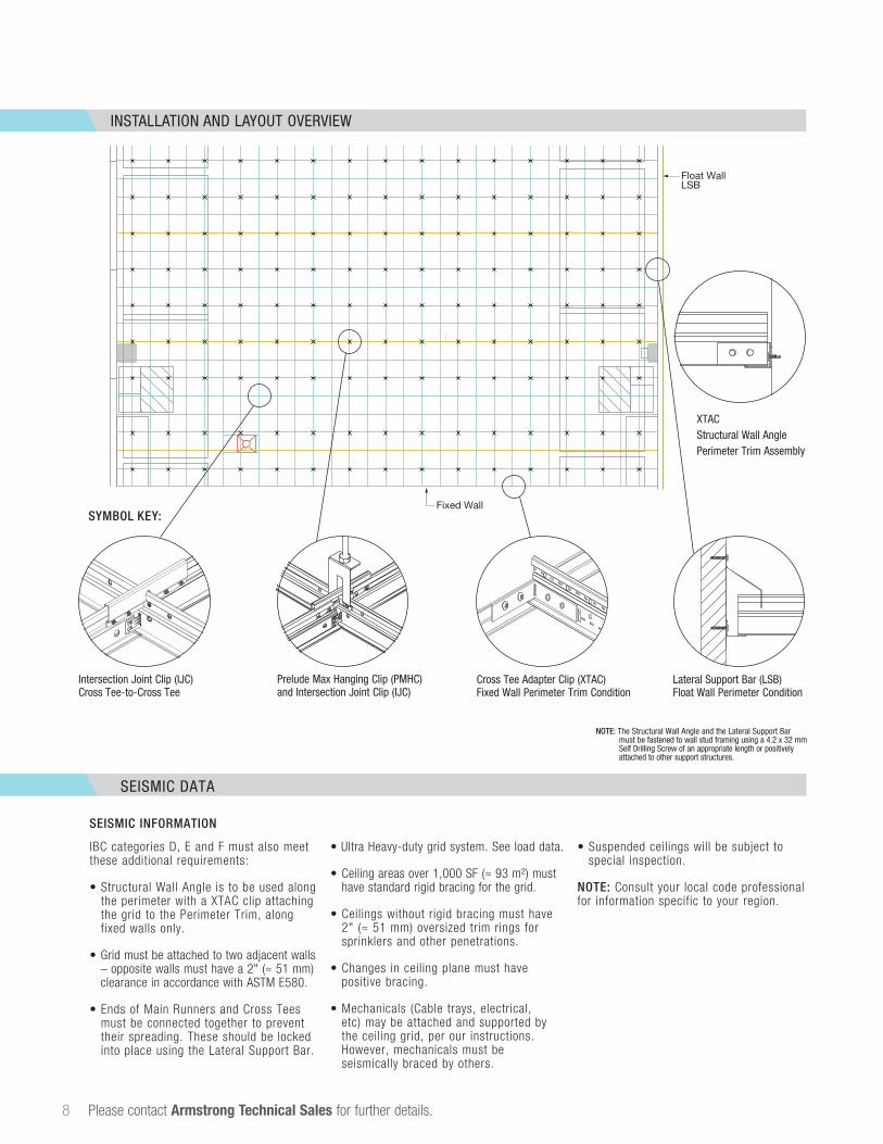
INSTALLATION AND LAYOUT OVERVIEW
8 Please contact Armstrong Technical Sales for further details.
SYMBOL KEY:
Intersection Joint Clip (IJC) Cross Tee-to-Cross Tee
Prelude Max Hanging Clip (PMHC) and Intersection Joint Clip (IJC)
Cross Tee Adapter Clip (XTAC)Fixed Wall Perimeter Trim Condition
Lateral Support Bar (LSB) Float Wall Perimeter Condition
NOTE: The Structural Wall Angle and the Lateral Support Bar must be fastened to wall stud framing using a 4.2 x 32 mm Self Drilling Screw of an appropriate length or positively attached to other support structures.
Float WallLSB
Fixed Wall
Float Wall
Fixed Wall
12'
12'
12'
12'
A-1A-1
A-1
SEISMIC DATA
SEISMIC INFORMATION
IBC categories D, E and F must also meet these additional requirements:
• Structural Wall Angle is to be used along the perimeter with a XTAC clip attaching the grid to the Perimeter Trim, along fixed walls only.
• Grid must be attached to two adjacent walls – opposite walls must have a 2" (≈ 51 mm) clearance in accordance with ASTM E580.
• Ends of Main Runners and Cross Tees must be connected together to prevent their spreading. These should be locked into place using the Lateral Support Bar.
• Ultra Heavy-duty grid system. See load data.
• Ceiling areas over 1,000 SF (≈ 93 m²) must have standard rigid bracing for the grid.
• Ceilings without rigid bracing must have 2" (≈ 51 mm) oversized trim rings for sprinklers and other penetrations.
• Changes in ceiling plane must have positive bracing.
• Mechanicals (Cable trays, electrical, etc) may be attached and supported by the ceiling grid, per our instructions. However, mechanicals must be seismically braced by others.
• Suspended ceilings will be subject to special inspection.
NOTE: Consult your local code professional for information specific to your region.
XTACStructural Wall AnglePerimeter Trim Assembly
POINT LOAD DATA
LOADING LAYOUTS
9
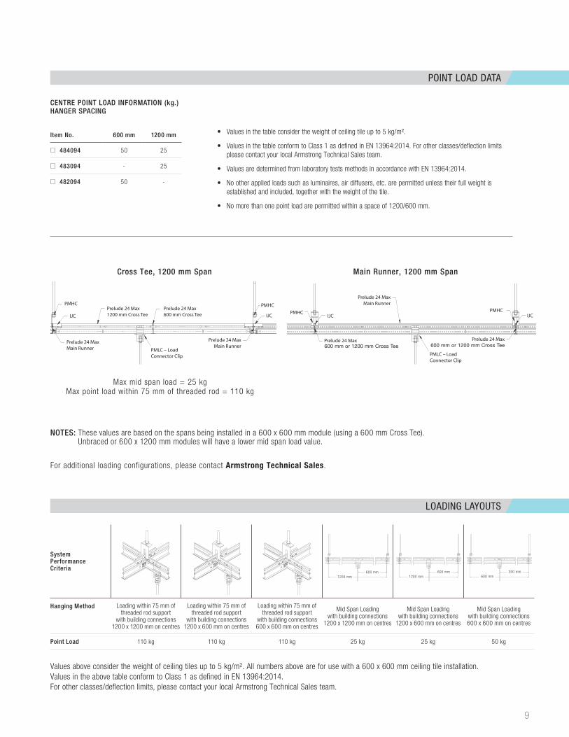
System Performance Criteria
Hanging Method Loading within 75 mm of threaded rod support
with building connections 1200 x 1200 mm on centres
Loading within 75 mm of threaded rod support
with building connections 1200 x 600 mm on centres
Loading within 75 mm of threaded rod support
with building connections 600 x 600 mm on centres
Mid Span Loadingwith building connections
1200 x 1200 mm on centres
Mid Span Loadingwith building connections
1200 x 600 mm on centres
Mid Span Loadingwith building connections 600 x 600 mm on centres
Point Load 110 kg 110 kg 110 kg 25 kg 25 kg 50 kg
NOTES: These values are based on the spans being installed in a 600 x 600 mm module (using a 600 mm Cross Tee). Unbraced or 600 x 1200 mm modules will have a lower mid span load value.
For additional loading configurations, please contact Armstrong Technical Sales.
Values above consider the weight of ceiling tiles up to 5 kg/m². All numbers above are for use with a 600 x 600 mm ceiling tile installation.Values in the above table conform to Class 1 as defined in EN 13964:2014.For other classes/deflection limits, please contact your local Armstrong Technical Sales team.
600 mm
1200 mm
600 mm
1200 mm
300mm
600 mm1200 mm
Cross Tee, 1200 mm Span Main Runner, 1200 mm Span
Prelude 24 Max1200 mm Cross Tee
Prelude 24 Max600 mm or 1200 mm Cross Tee
Prelude 24 Max600 mm or 1200mm Cross Tee
Prelude 24 Max600 mm Cross Tee
Prelude 24 MaxMain Runner
Prelude 24 MaxMain Runner
Prelude 24 MaxMain Runner
PMLC – Load Connector Clip
PMLC – LoadConnector Clip
PMHCPMHC
PMHCPMHCIJC IJC
IJCIJC
Max mid span load = 25 kg Max point load within 75 mm of threaded rod = 110 kg
Prelude 24 Max1200 mm Cross Tee
Prelude 24 Max600 mm or 1200 mm Cross Tee
Prelude 24 Max600 mm or 1200mm Cross Tee
Prelude 24 Max600 mm Cross Tee
Prelude 24 MaxMain Runner
Prelude 24 MaxMain Runner
Prelude 24 MaxMain Runner
PMLC – Load Connector Clip
PMLC – LoadConnector Clip
PMHCPMHC
PMHCPMHCIJC IJC
IJCIJC
600 mm or 1200 mm Cross Tee 600 mm or 1200 mm Cross Tee
600 mm1200 mm
600 mm600 mm
300 mm
Item No. 600 mm 1200 mm
484094 50 25
483094 - 25
482094 50 -
• Values in the table consider the weight of ceiling tile up to 5 kg/m².
• Values in the table conform to Class 1 as defined in EN 13964:2014. For other classes/deflection limits please contact your local Armstrong Technical Sales team.
• Values are determined from laboratory tests methods in accordance with EN 13964:2014.
• No other applied loads such as luminaires, air diffusers, etc. are permitted unless their full weight is established and included, together with the weight of the tile.
• No more than one point load are permitted within a space of 1200/600 mm.
CENTRE POINT LOAD INFORMATION (kg.)HANGER SPACING
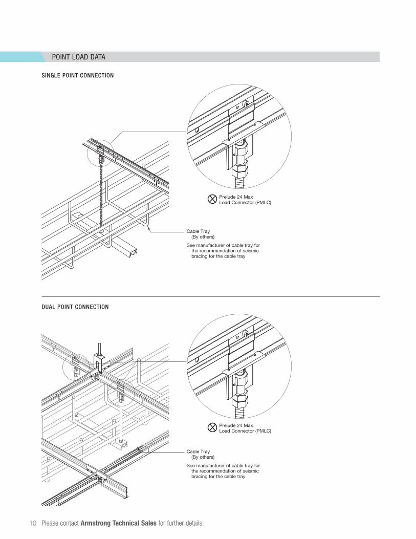
POINT LOAD DATA
10 Please contact Armstrong Technical Sales for further details.
SINGLE POINT CONNECTION
Cable Tray (By others)
See manufacturer of cable tray for the recommendation of seismic bracing for the cable tray
IHC – Intersection Hanging Clip
SHC – Supplemental Hanging Clip
IHC – Intersection Hanging Clip
3/8 –16"Heavy Hex
Locknut
3/8 –16" Threaded Rod
3/8 –16" Heavy Hex Nut
IHC Clip
Imperial: 3/8" Flat Washer, 1/8" Thickness, 7/8" Width,
Case Hardened Steel,Grade C-1010
(MSC Item# 74213505)
M5 x 6mm, 0.8mmPan Head
Machine Screws
* Threadlocker Adhesive Required
3/8 –16" Threaded Rod
3/8 –16" Heavy Hex Nut
3/8 –16" Heavy Hex Locknut
SHC Clip
SHC – Supplemental Hanging Clip Installation
IHC – Intersection Hanging Clip Installation
Make sure thatthe head of the
rivet goes throughthe XL Clip.
The expandedportion of the rivet
needs to expandon the IHC clip.
Blind Steel Pop Rivets1/8" Dia. x .337" Long
.126" – .186" Grip LengthShear Strength: 260 lbs.
PMLC – Load Connector Clip
3/8 –16" Heavy Hex Locknut
1
3/8 –16" Heavy Hex Nuts
PMLC Clip
Sharp PointTruss Head
Screw
3/8 –16"Threaded Rod
Load Connector Clip Installation
IJC – Intersection Joint Clip
2
3
(4) #8 x 1/2" LongSharp Point Truss Head Screws
Top Lock Main Beam
Splice Clip
TLMBS – Top Lock Main Beam Splice Clip
Top Lock Main BeamSplice Clip Installationon two Prelude XL Max
Main Beams
DUAL POINT CONNECTION
SYMBOL KEY:
Cable Tray Insatll Single Point
Prelude Max Load Connector
Cable Tray
Prelude 24 MaxLoad Connector (PMLC)
Cable Tray (By others)
See manufacturer of cable tray for the recommendation of seismic bracing for the cable tray
SYMBOL KEY:
Cable Tray Insatll Single Point
Prelude Max Load Connector
Cable Tray
Prelude 24 MaxLoad Connector (PMLC)
IHC – Intersection Hanging Clip
SHC – Supplemental Hanging Clip
IHC – Intersection Hanging Clip
3/8 –16"Heavy Hex
Locknut
3/8 –16" Threaded Rod
3/8 –16" Heavy Hex Nut
IHC Clip
Imperial: 3/8" Flat Washer, 1/8" Thickness, 7/8" Width,
Case Hardened Steel,Grade C-1010
(MSC Item# 74213505)
M5 x 6mm, 0.8mmPan Head
Machine Screws
* Threadlocker Adhesive Required
3/8 –16" Threaded Rod
3/8 –16" Heavy Hex Nut
3/8 –16" Heavy Hex Locknut
SHC Clip
SHC – Supplemental Hanging Clip Installation
IHC – Intersection Hanging Clip Installation
Make sure thatthe head of the
rivet goes throughthe XL Clip.
The expandedportion of the rivet
needs to expandon the IHC clip.
Blind Steel Pop Rivets1/8" Dia. x .337" Long
.126" – .186" Grip LengthShear Strength: 260 lbs.
PMLC – Load Connector Clip
3/8 –16" Heavy Hex Locknut
1
3/8 –16" Heavy Hex Nuts
PMLC Clip
Sharp PointTruss Head
Screw
3/8 –16"Threaded Rod
Load Connector Clip Installation
IJC – Intersection Joint Clip
2
3
(4) #8 x 1/2" LongSharp Point Truss Head Screws
Top Lock Main Beam
Splice Clip
TLMBS – Top Lock Main Beam Splice Clip
Top Lock Main BeamSplice Clip Installationon two Prelude XL Max
Main Beams
Advisory noteAll photographic and design elements supplied in this brochure do not necessarily reflect any recommendation by any of the companies named in this brochure as to the proper use or recommended methods of installation of suspended ceilings and are supplied as informative material. For technical reasons in printing, differences may appear between colours printed in this brochure and the actual product. The choice of colours should always be made from a sample of the product. All statements and technical information contained in this brochure, or any publication of the companies named in this brochure, relating to Armstrong Ceilings are based on results obtained under laboratory test conditions. It is the responsibility of the used to verify with the seller of the products in writing that such statements and information are appropriate to the specific use intended. Sales of the products and liability of the selling companies are in accordance with the terms and conditions of sale in the selling company. All product specifications are subject to modifications without prior notice.
Inspiring Great Spaces® is a trademark of AFI Licensing LLC; RAL is a trademark of RAL gemeinnutzige GmbH;SketchUp® is a registered trademark of Trimble Navigation Limited; Revit® is a registered trademark of Autodesk, Inc.All other trademarks are property of AWI Licensing LLC and/or affiliates.© 2018 AWI Licensing LLC