preliminary dimensioning of reinforced concrete sections · 2015-04-03 · gračevinar 122014...
TRANSCRIPT

Građevinar 12/2014
1125GRAĐEVINAR 66 (2014) 12, 1125-1143
DOI: 10.14256/JCE.1056.2014
Preliminary dimensioning of reinforced concrete sections
Primljen / Received: 3.4.2014.
Ispravljen / Corrected: 11.12.2014.
Prihvaćen / Accepted: 29.12.2014.
Dostupno online / Available online: 10.1.2015.
Authors:Professional paper
Tomislav Kišiček, Ivan Petrić
Preliminary dimensioning of reinforced concrete sections
This paper describes a procedure for the development and use of tables for the preliminary design of reinforced concrete elements exposed to bending action, in compliance with appropriate ultimate and serviceability limit state criteria. The use of tables for defining basic dimensions of cross-sectional elements enables designers to avoid the "trial and error" approach, while also ensuring fast and simple preliminary dimensioning as a preparation for the subsequent more detailed design of structural elements.
Key words:preliminary dimensioning, ultimate limit state, serviceability limit state, preliminary design tables
Stručni radTomislav Kišiček, Ivan Petrić
Preliminarno dimenzioniranje armiranobetonskih presjeka
U radu je opisan postupak izrade i korištenja tablica za preliminarno dimenzioniranje armiranobetonskih elemenata, izloženih savijanju, prema graničnim stanjima nosivosti i uporabljivosti. Korištenjem tablica, kod određivanja osnovnih dimenzija presjeka elemenata izbjegava se pristup "pokušaja i pogrešaka" i omogućuje brzo i jednostavno osnovno dimenzioniranje presjeka kao priprema za daljnji, detaljniji proračun konstrukcijskih elemenata.
Ključne riječi:preliminarno dimenzioniranje, granično stanje nosivosti, granično stanje uporabljivosti, tablice za preliminarni proračun
FachberichtTomislav Kišiček, Ivan Petrić
Präliminierte Bemessung von Stahlbetonbauteilen
In dieser Arbeit wird ein Verfahren zur Erstellung und Anwendung von Tabellen für die präliminierte Bemessung von Stahlbetonbauteilen unter Biegebeanspruchung für die Grenzzustände der Tragfähigkeit und Gebrauchstauglichkeit dargestellt. Durch die Anwendung von Tabellen bei der Ermittlung von Querschnittsmaßen wird das Probierverfahren umgangen und eine einfache grundgelegene Bemessung ermöglicht, die als Vorbereitung für weitere ausführlichere Berechnung der Bauelemente dient.
Schlüsselwörter:Präliminierte Bemessung, Grenzzustand der Tragfähigkeit, Grenzzustand der Gebrauchstauglichkeit, Präliminierte Berechnungstabellen
Assit.Prof. Tomislav Kišiček, PhD. CEUniversity of ZagrebFaculty of Civil [email protected]
Ivan Petrić, MCETSB Ingenieurgesellschaft mbHDarmstadt, [email protected]

Građevinar 12/2014
1126
Tomislav Kišiček, Ivan Petrić
GRAĐEVINAR 66 (2014) 12, 1125-1143
1. Introduction
Although a preliminary dimensioning of reinforced-concrete elements is usually based on the ultimate limit state (ULS) requirements and methods, the serviceability limit state (SLS) should equally be taken into account in this respect. The dimensioning of structural elements according to the ultimate limit state method is based, in addition to the known dimensions of elements, on the determination of the required reinforcement in the cross-section. However, it is sometimes necessary to additionally change cross-sectional dimensions. This is more often necessary in case of the serviceability limit state. In fact, the factors mostly influencing the deformation limiting requirements (i.e. requirements relating to deflection, displacement, curvature) are cross sectional dimensions of the elements, while these requirements are only to a lesser extent influenced by the quantity of reinforcement and type of concrete.In many cases, the indication that dimensions should be changed is obtained only according to the final result of calculation for the serviceability limit state. So it can happen that the necessary requirement has not been met, or that the result greatly errs on the side of safety. In both cases, the element dimensions must be changed, either to meet serviceability requirements or to achieve greater economy, i.e. to make material savings.Thus, the calculation must be made from the very beginning. This can be a time-consuming process if a big number of different elements are present in the structure, because calculations for structural elements based on the serviceability limit state can be quite extensive.In addition, it is often necessary to conduct preliminary dimensioning of elements, especially in building construction, in cases when only basic dimensions of the building are known.It is only then that a more detailed elaboration of the design can be made, making use of approximately final dimensions of structural elements.The need obviously exists to simplify the basic calculation, so that preliminary (preparatory, basic) dimensions of elements for both these limit states can be determined in a rapid and simple manner.This paper describes the procedure for preparing and applying tables for the preliminary dimensioning of reinforced-concrete sections according to the ultimate and serviceability limit states, in accordance with new standards from the series HRN EN 1990 [1], HRN EN 1991-1-1 [2], and HRN EN 1992-1-1 [3].The tables can be used, in case of a small number of input data, for the rapid and simple determination of basic dimensions of reinforced-concrete elements and reinforcement, as needed to meet the ultimate and serviceability limit states. This procedure is illustrated below by means of a calculation example.
2. Ultimate limit state
The ultimate limit state is a set of limit states that take into account [1]: safety of people and/or safety of structures/buildings and, in some cases, the safety of objects within such buildings. The failure of reinforced-concrete elements subjected to bending load is considered in the paper. The analysis of the reinforcement required
in the cross-section of such elements is conducted based on the known procedure using calculation tables, i.e. as described in papers [4, 5, 13]. Tables for practical calculation are also presented in these papers. The need for preparing such tables arose due to occurrence of concrete classes with the strengths greater than C50/60 in HRN EN 1992-1-1 [3], and due to different definition of design strength of concrete according to these standards. The design (s - e) diagrams for concrete classes greater than C50/60 differ from those for concrete classes C12/16 to C50/60, and so the existing tables can not be used for dimensioning reinforced-concrete elements made of such (higher) concrete classes. This is why different dimensioning tables have been prepared in papers [4, 5, 13] for each of these concrete classes.
3. Serviceability limit state
The serviceability limit state is the state beyond which serviceability criteria specified in the design are disturbed or disrupted. The criteria are related to the functioning of a structure or structural elements in normal use, comfort of people, and appearance of building (due to deformation of its structure or a part of the structure). Serviceability criteria should be defined together with the client and set separately for each project, depending on the intended use of the building/structure. The limit state of serviceability comprises [3, 6]: the ultimate state of deformation, cracking, stress and fatigue.
3.1. Limit state of deformation – limit state of deflection
The term deformation implies deflections, curvature, elongation or shortening, twisting and change of inclination of structural elements. Deflection is a significant parameter of the limit state of deformation. In case of reinforced-concrete elements the deflection occurs due to load (bending and shear). The deflection due to bending is the most often calculated deflection because deflections caused by transverse forces are much lower and are almost always neglected.Deflections depend on the type, size and duration of load, on geometrical values of elements (span, width, height, shape), and on mechanical properties of materials (concrete and reinforcement). When calculating deflection, one also has to take into account concrete properties that change with time (concrete creep and shrinkage, and cracking).According to HRN EN 1992-1-1 [3], the limit state of deflection is considered met if the maximum deflection of a structural element amounts to less than 1/250 of the design span of the element, Leff, i.e. if it is lower that the limit deflection values vlim given in HRN EN 1992-1-1. s 7.4.1 [3].However, the deflection value need not always to be calculated. One can define, as a basic condition, the limit values of the design span to static height (slenderness) ratio, Leff/d, for individual static systems. If the slenderness of the studied element is lower than the limit value, the deflection requirement is considered met. If this is not the case, a detailed deflection calculation most be made [3].

Građevinar 12/2014
1127GRAĐEVINAR 66 (2014) 12, 1125-1143
Preliminary dimensioning of reinforced concrete sections
The following expressions are defined in HRN EN 1992-1-1 for the determination of the limit span to effective depth of a cross-section ratio:
Ld
K f f= + + −
11 15 3 2 10 0
32
, ,ck ckρρ
ρρ for r ≤ r0 (1)
Ld
K f f= +−
+
11 15 112
0
0
,'
'ck ck
ρρ ρ
ρρ for r > r0 (2)
where:
Ld
- limit (design) span to static height ratio
K - factor that takes into account various static system types
fck - characteristic compressive strength of concrete in N/mm2
As1 - cross-sectional area of tensile reinforcementAs2 - cross-sectional area of compressive reinforcementd - effective depth of cross sectionb - total section width
ρ0310= − fck - reference reinforcement ratio
ρ =⋅Ab d
s1
- coefficient of tensile reinforcement
ρ ' =⋅Ab ds2
- coefficient of compressive reinforcement
The elements with the reinforcement ratio of r ≤ 0,5 % are considered to be weakly stressed (slabs), while elements with the reinforcement ratio of r ≥ 1,5 % are considered to be strongly stressed (beams) [6]. Values given in Table 1 are conservative, and it can be proven by calculation that deflections can be met even with greater values of the ratio Leff/d (slenderness), compared to the cited ones [3]. Intermediate values of the coefficient r can be interpolated linearly [3, 6, 13] For all static systems given in Table 1, except for flat slabs, a shorter span is introduced into procedure for the determination of [4, 5, 13].It is assumed in expressions (1), (2) and in Table 1 that the stress in in reinforcement, for the frequent and quasi-permanent combination of loads, on an cracked cross section, amounts to
ss = 310 N/mm2, and that the steel grade is B500. In addition, it is assumed in Table 1 that t the concrete class is C30/37 [3, 6, 13].The slenderness Leff/d varies more greatly depending on the concrete class, as shown by the relationship between the reinforcement coefficient r and slenderness, Leff/d, for concrete classes from C12/15 to C90/105, for the static system of a free beam (K = 1.0), according to expressions (1) and (2) [13] (Figure 1).
Figure 1. Diagram of ratio Leff/d as related to coefficient r [%] for each concrete class [13]
It should be noticed that the Expression (2), unlike Expression (1), takes into account influence of the compressive reinforcement. However, the diagram in Figure 1 is made under assumption that r’ = 0 for Expression (2), as the contribution of compressive reinforcement is sufficiently small to be neglected during calculation of single reinforcement of cross section, in span and at support. In case of duble reinforced of cross section, the compressive reinforcement can influence an increase in the allowed slenderness, depending on the relationship between cross-sectional areas of compressive and tensile reinforcement.As the greatest possible slenderness, Leff/d, amounts to 28 for the minimum ratio of reinforcement of about r = 0,15 % and for the simply supported beam static system (Table 1), this slenderness value is taken as the maximum allowable value.
Static system KLightly stressed concrete (of the slab) Highly stressed
concrete (of the beam)r = 1,5 %r = 0,15 % r = 0,5 %
Simply supported beam, one- or two-way spanning simply supported slab 1,0 28 20 14
End span of continuous beam or one-way continuous slab or two-way spanning slab continuous over the long side 1,3 36 26 18
Interior span of beam or one-way or two-way spanning slab 1,5 32 30 20
Slab supported on columns without beams (flat slab) 1,2 34 24 17
Cantilever 0,4 10 8 6
Tablica 1. Limit ratio Leff/d when deflection calculation is not needed [3, 6, 13]

Građevinar 12/2014
1128
Tomislav Kišiček, Ivan Petrić
GRAĐEVINAR 66 (2014) 12, 1125-1143
Reference ratio of reinforcement ρ0 310= ⋅ −fck are marked by points for individual concrete classes in the diagram (Figure 1).For assumptions in expressions and tables, and in case when the real stress in reinforcement ss, differs from 310 N/mm2, or when another type of steel is used, the expressions (1) and (2), and hence the values given in Table 1 and diagram (Figure 1), must be multiplied by the smaller of the following two correction factors [3, 6, 13]:
f ff
AA3 3
310 500= = ⋅σ s yk
s,prov
s,req
ili (3)
where:As,prov - provided (selected) tensile reinforcement area in cross-
sectionAs,req - required (calculated) tensile reinforcement area in the
studied cross-section for assuming the bending momentfyk - characteristic yield strength of reinforcement [N/mm2].
Similarly, the values from Table 1 and the values from the Diagram in Figure 1 are multiplied with the following reduction factors [4, 5, 13]: a) for T beams in which the ratio of participating compressive width of the flange to web width is greater than 3beff/bw > 3, the factor amounts to 0.8; b) for all elements (except
for flat slabs) of more than 7.0 m in span that carry partition walls, the factor amounts to 7,0/Leff; c) for flat slabs of more that 8.5 m in span the reduction factor amounts to 8,5/Leff.To be able to use values from the Diagram in Figure 1 for any static system, every static system of span L can be reduced to the system of simply supported beam of "normalised" span Ln during the preliminary dimensioning process, using the factor K that takes into account various types of static systems (Table 1). In this case, the following is valid:
L LKn = (4)
3.2. Limit state of cracking
This serviceability limit state limits the crack width so as to prevent deterioration of structure due to reinforcement corrosion. In addition to loading, the cracking can be caused by: stress due to temperature changes, creep and shrinkage of concrete, differential settlements of supports, rotation of supports, or deformation of connection elements [6]. Cracks are not a hindrance if their width does not exceed limit values (Table 7.1N from [3]) that are specified for classes of element exposure or external appearance of elements.In the preparation of tables for preliminary dimensioning of
ss[N/mm2] ss / fyk
Concrete class
C20/25 C25/30 C30/37 C35/45 C40/50
Limit bar diameter values [mm]
160 0.32 43 51 57 63 68
170 0.34 38 45 50 55 60
180 0.36 33 40 44 49 53
190 0.38 30 35 39 43 47
200 0.40 27 32 35 39 42
210 0.42 24 28 32 35 38
220 0.44 22 26 29 32 34
230 0.46 20 23 26 29 31
240 0.48 18 21 24 26 28
250 0.50 16 19 22 24 26
260 0.52 15 18 20 22 24
270 0.54 14 16 18 20 22
280 0.56 13 15 17 18 20
290 0.58 12 14 15 17 19
300 0.60 11 13 14 16 17
310 0.62 10 12 13 15 16
320 0.64 9 11 12 14 15
340 0.68 8 10 11 12 13
360 0.72 7 8 9 10 11
380 0.76 6 7 8 9 10
400 0.80 6 7 7 8 9
450 0.90 4 5 6 6 7
Table 2.Limit bar diameter values for checking characteristic crack widths for concrete classes C20/25 to C40/50
Građevinar 12/2014
1129GRAĐEVINAR 66 (2014) 12, 1125-1143
Preliminary dimensioning of reinforced concrete sections
reinforced-concrete elements (without prestressing), and in order to place dimensioning on the side of safety, the requirement wmax = 0,3 mm, for the quasi-permanent combination of load, is taken into account as a relevant requirement.Special measures for limiting cracking width are not needed for reinforced-concrete slabs in buildings, which are 20 cm in thickness and stressed by bending, without a significant longitudinal axial tension [6]. At that, the maximum spacing between main reinforcing bars and secondary transverse bars (which do not account for less than 20% of the main reinforcing bars) should not exceed the values specified in section 9.2.1.1 of the standard HRN EN 1992-1-1 [3] or in section 5.5.1 from [4].Assuming that the provided cross-sectional area of reinforcement, for the ultimate limit state, meets the minimum reinforcement requirement for limiting propagation of cracks, then this limitation of crack propagation is achieved without direct calculation, for the characteristic crack width of wk = 0,3 mm, by limiting the reinforcing bar diameter and reinforcing bar spacing according to Table 2.6 from [13] or Tables 7.2N and 7.3N [3].Limit reinforcing bar diameter values depending on stress in reinforcement, for crack propagation control and for several concrete classes, are given below in Table 2. The procedure for determining limit diameter values was conducted according to Section 7.3.3 of Eurocode 2 – Commentary, European Concrete Platform ASBL, Bruxelles, June 2008 [9], i.e. according to the following expression:
φσ σ
=−( )
⋅ − ⋅
⋅
⋅ ⋅⋅ ⋅ ⋅
wk
E cf k k
k kk
t
s
s
ct,eff c
s 1 213 4
0 425,
,⋅⋅
⋅ ⋅ −( )hk h d
cr
2 5, ' (5)
Considering the following assumptions based on [9]:
wk = 0,3 mm - characteristic crack widthEs = 200000 N/mm2 - steel bar elastic modulusc = 25 mm - concrete cover thicknesskt = 0,4; kc = 0,4; k = 1,0 0425 · k1 · k2 = 0,17hcr / (h-d) = 5,0 cmk' = 1,0
The Expression (5) can be written as follows:
φσ σ
= −
⋅
⋅100000 854 71
s
ct,eff
s
, f (6)
Deviations obtained according to Expression (6) from values given in Tables 7.2N and 7.3N (according to HRN EN 1992-1-1 [3]) are acceptably small.If limit diameters given in Table 2 are considered, it can be seen that limit diameter values, at the same stress in reinforcement, increase with an increase in concrete class. Thus, in higher concrete classes the limit stress is greater for the same bar diameter.In order to meet the limit cracking requirement in preliminary calculation, e.g. for the concrete class C30/37, the stress in reinforcement ss should not exceed 320 N/mm2 for the quasi-permanent combination of loads, in case the beam element is reinforced with bars 12 mm in diameter.
3.3. Limit state of stress
This limit state curbs down stresses at design load so as to prevent excessive plastic deformation and cracking of reinforced-concrete structures. Such occurrences might endanger durability and serviceability of structures. The stress is limited in concrete and steel reinforcement as follows. In order to avoid occurrence of longitudinal cracks in concrete (propagation of splitting forces), and hence the loss of durability of reinforced-concrete elements due to influence of ambient conditions, the concrete stress requirements for stress in concrete sc must be fulfilled:
a) for characteristic combination of loads:
sc ≤ 0,6 · fck (7)
b) or quasi-permanent combination of loads:
sc ≤ 0,45 · fck (8)
To limit an excessive deformation of reinforcement, and hence the propagation of cracks, the requirements for stress in steel ss must be fulfilled
a) For characteristic combination of loads:
sc ≤ 0,8 · fyk (9)
b) for quasi-permanent combination of loads (from requirements of limit state of cracking, Table 2) the alowed stress is limited separately for each class of concrete and reinforcement, e.g.:
sc ≤ 0,64 · fyk for concrete C30/37 and bars 12 mm in diameter (10)
4. Tables for preliminary dimensioning of reinforced-concrete elements
4.1. Limit state of deflection
The dimensioning of reinforced-concrete elements according to the ultimate limit state is based on the equilibrium of forces within the cross-section of elements, i.e. on the equilibrium between the bending moment due to load and the carrying capacity moment of the cross-section. Tables [4, 5, 13] were prepared for the dimensioning of rectangular cross-sections with regard to bending action. Based on the assumed pairs of strain of the steel reinforcement subjected to tension and concrete subjected to compression, and assuming that the equilibrium of internal force in cross-section has been achieved (Figure 2), the following values needed for obtaining the area of tensile reinforcement are calculated: x - coefficient of position of neutral axis, z - coefficient of the lever arm of internal forces, mRd - dimensionless bending moment for cross-section, w - mechanical coefficient of reinforcement, av - coefficient of fill of concrete design diagram, and ka - coefficient of position of the

Građevinar 12/2014
1130
Tomislav Kišiček, Ivan Petrić
GRAĐEVINAR 66 (2014) 12, 1125-1143
compressive stress resultant for concrete. A detailed procedure for preparation of such tables is presented in papers [4, 5, 13].The relationship between the ultimate limit state and serviceability limit state (deflection) is the tensile reinforcement ratio, which influences the limit slenderness, Leff/d, through which the limit state of deflection of a reinforced-concrete element is met. The tensile reinforcement ratio is defined by the following expression:
ρ ω=⋅
= ⋅Ab d
ff
s1 cd
yd (11)
Assuming that the steel B500 is used, it can be seen that the tensile reinforcement ratio depends of the concrete class, i.e. on the design strength and the mechanical coefficient of reinforcement w, which is unambiguously defined for each pair of deformations ec and es1 through dimensioning tables (from [4, 5, 13]).Therefore, according to ultimate limit state, the existing dimensioning tables (from [4, 5, 13]) can be extended by reinforcement ratio for individual concrete classes, which determine the part of tensile reinforcement that is needed to meet the ultimate limit state requirement.At that, care should be taken about the minimum and maximum reinforcement. The following requirements for minimum reinforcement (according to HRN EN 1992-1-1, Section 9.3.1.1.) should be met [3]:
A b ds1,min = ⋅ ⋅0 0013, (12)
A b d ffs1,minctm
yk
= ⋅ ⋅ ⋅
0 26, (13)
here the greater value is relevant, i.e. using the expression (11), the greater reinforcement ratio from the following values:
ρmin = 0 0013, (14)
ρminctm
yk
= ⋅
0 26, f
f (15)
In addition, the following requirements for maximum reinforcement must be met: according to the draft national annex HRN [10]
As1,max = 0,222 · Ac (16)
where Ac = b·h ≈ b·1,1·d
A b d ffs1,maxcd
yd
= ⋅ ⋅ ⋅
ωlim according to [3] (17)
where the relevant value is the lower value, i.e. the lower of the following reinforcement ratios:
ρmax = ⋅ =0 022 11 0 0242, , , (18)
ρ ωmaxcd
yd
= ⋅
lim
ff (19)
After analysis of integral preliminary dimensioning tables given in Appendix 1, it can be noticed that the minimum reinforcement requirement (14) is relevant for concrete classes C12/15, C16/20 and C20/25, while the minimum reinforcement requirement (15) is relevant for other classes of concrete.In order to restrict tables in the zone of single reinforcement, the requirement (19) for maximum reinforcement is relevant for concrete classes from C12/15 to C40/50 and for concrete classes from C55/67 to C70/85, while the maximum reinforcement requirement (18) is relevant for other classes of concrete. The above maximum reinforcement amounts must
Parameters given in Figure 2 are:b - width of cross-sectionh - height of cross-sectiond - effective depth of cross-sectiond1 - distance between centre of tensile reinforcement and tensile
edge of cross-sectionAs1 - area of tensile reinforcementx - height of compressive area of cross-section
ec - strain of compressive edge of cross-sectiones1 - strain of tensile reinforcementec2 - strain of concrete when compressive strength is attainedMEd - design value of bending momentfcd - design compressive strength of concreteFc - compressive stress resultant for concreteFs1 - tensile stress resultant for reinforcementz - lever arm of internal forces
Figure 2. Cross section in span subjected to bending without longitudinal force, with stress and strain distribution, and with position of resulting compressive and tensile stresses, [5]

Građevinar 12/2014
1131GRAĐEVINAR 66 (2014) 12, 1125-1143
Preliminary dimensioning of reinforced concrete sections
not be exceeded for single reinforcement. Maximum amounts are marked in colour in tables (in the appendix).An appropriate slenderness limit, Leff/d, which must not be exceeded by the studied element, can be defined for every defined class of concrete and reinforcement ratio r, based on the procedure described in Section 3.1 and using expressions (1) and (2). Thus the requirement for the limit state of deflection is met without additional calculation.
4.2. Limit state of stress
According to [3, 5], the linear analysis of elements based on elastic theory is used for the limit state of stress, unlike the simplified plastic analysis (model) that is used for preparing the table for dimensioning cross-sections with regard to ultimate limit state.A reduced stiffness, corresponding to cracked cross-sections and neglecting tensile stiffening while including creep effects, can be assumed for long-term actions. The elastic modulus ratio ae , is defined according to [3, 6, 13]:
αes
cm
=EE
for short-term load, i.e. for t = 0 (20)
αes
c,eff
=E
E for long-term load, i.e. for t t = ∞ (21)
The elastic modulus ratio ae, defined in expression (21), is used in further calculations. The effective elastic modulus for concrete, used in expression (21), can be defined from the secant elastic modulus by means of the following expression:
(22)
This takes into account the effect of creep in case of long-term load. An accurate calculation of the final creep coefficient, j(∞, t0), is quite complex due to a great number of factors it is dependent on. When a high accuracy is not requested, the final creep coefficient value can be defined from diagram in Figure 3.1, based on HRN EN 1992-1-1 [3], but provided that the concrete is not exposed to
compressive stress in excess of 0,45 · fck(t0), at the concrete age during the loading time [3]. In addition, due to lack of accurate analyses, the use of the final creep factor value of j(∞, t0) = 2,0, according to [12], is proposed. When defining in [13] the coefficient of height of elastic compressive area xe, the authors show the influence of creep factor ranging from j(∞, t0) = 1,0 to j(∞, t0) = 4,0 on its value. It can be seen that deviations are not great. As efforts are made to simplify as much as possible the preliminary calculation, and as a great accuracy is not required, the value of j(∞, t0) = 2,0 is adopted in this paper as well as in the paper [12]. In case of a detailed calculation of the serviceability limit state, the concrete shrinkage must be taken into account, in addition to creep, with regard to long-term actions. Shrinkage deformations are taken into account only for a detailed calculation of deflection, in case when the basic requirement regarding limit ratios Leff/d is not fulfilled. As preliminary dimensioning tables are based on the fulfilment of the basic requirement regarding limit ratios, the influence of shrinkage is neglected in this case.
4.2.1. Coefficient of height of compressive area for serviceability limit state
According to Figure 3, based on equilibrium requirement regarding typical moments:
MEk = MRk (23)
and using the expression for equilibrium of bending moments during calculation according to the ultimate limit state, we can derive the expression for the ratio of stress in concrete to typical design strength, sc/fck:
µk ck c⋅ ⋅ ⋅ = ⋅b d f F z2 (24)
µ σk ck c e e⋅ ⋅ ⋅ = ⋅ ⋅ ⋅ −
b d f x b d x2 1
213 (25)
and we obtain:
Figure 3. Elastic model of a singly reinforced cross-section in span under influence of bending, with stress and strain distribution, and with position of compressive and tensile stress resultants, [11]
Parameters used in Figure 3 (other than those defined for Figure 2):xe - height of compressive area of elastic cross-sectionsc - stress at compressive edge of cross-section
ss1 - stress of tensile reinforcementae - ratio of elastic moduli for steel and concrete

Građevinar 12/2014
1132
Tomislav Kišiček, Ivan Petrić
GRAĐEVINAR 66 (2014) 12, 1125-1143
σ µξ ξ
c
ck
k
e ef=
⋅ −
2
13
(26)
Similarly, the expression for the ratio of stress in steel reinforcement to characteristic yield strength ss1/fyk can also be derived:
µk ck s⋅ ⋅ ⋅ = ⋅b d f F z2 (27)
µ σk ck s1 s1 e⋅ ⋅ ⋅ = ⋅ ⋅ −
b d f A d x2 1
3 (28)
and we obtain:
σ µ
ρξ
s1
yk
k
yk
ck
ef ff
=⋅ ⋅ −
1
3
(29)
The coefficient of height of elatic compressive area xe can be expressed as:
ξσ
α σ
es
e c
=+
⋅
1
1 (30)
Using expressions (26) and (29), it can be written as follows:
ξµρ
αµξ
ξ
α ρ
ξα ρ
ek yk ck
yk
ek ck
e
e
e
e
e
=
+
⋅ ⋅⋅
⋅⋅
=
+⋅
=+
⋅
1
1 2
1
1 2
1
12
f ff
f
(31)
and expressed in relation to the reinforcement ratio r and elastic modulus ratio ae:
ξ α ρα ρe ee
= ⋅ ⋅ +⋅
−
1 2 1 (32)
Using the expression (32), the coefficient xe, can unequivocally be defined for each concrete class and reinforcement ratio, r. It is important to take into account the difference between the coefficients of height of compressive area x, as defined by the table for dimensioning cross-section to bending action, and coefficients of height of elastic compressive area xe. In fact one coefficient x, exists for each pair of strains for concrete classes from C12/15 to C50/60, but one coefficient xe, exists for each class separately, because of the elastic modulus ratio, ae, which is different for each class of concrete. Each class has its own coefficients x and xe for concrete classes ksc > C50/60.Coefficients ksc and kss link the simplified plastic model of cross section for the ultimate limit state (Figure 2) and the elastic model of cracked cross-section for the serviceability limit state (Figure 3). This establishes a direct relationship between the stress ratios sc/fck and ss1/fyk and the characteristic and design bending moment ratio, MEk/MEd, as shown below.
4.2.2. Stress ratio sc/fck
Using Figure 2 and according to the cross-sectional equilibrium, the following is valid for the design bending moment:
M f b x d k xEd cd v a= ⋅ ⋅ ⋅ ⋅ − ⋅( )α (33)
Using Figure 3 and according to the cross-sectional equilibrium, the following is valid for the characteristic bending moment:
M x b d xEk
c e e
3=
⋅⋅ ⋅ −
σ2 (34)
According to expression (33), the following is valid for the design compressive strength of concrete:
f Mb x d k xcd
Ed
v a
=⋅ ⋅ ⋅ − ⋅( )α (35)
With the partial safety factor for concrete of gC = 1,5 the characteristic compressive strength of concrete is:
f Mb x d k xck
Ed
v a
=⋅
⋅ ⋅ ⋅ − ⋅( )15,
α (36)
The following can then be derived from expressions (34) and (36):
σαc
ckv
e
a
e
Ek
Ed
3f
xx
d k x
d xMM
= ⋅ ⋅ ⋅− ⋅
−⋅
215,
(37)
If the coefficients x = x/d i xe = xe/d, are inserted, the expression (37) can be written as follows:
σα
ξξ
ξξ
c
ckv
e
a
e
Ek
Ed
3f
k MM
= ⋅ ⋅ ⋅− ⋅
−⋅
2 015
1
1
,,
(38)
If the coefficient is defined:
k kσ α
ξξ
ξξc v
e
a
e
3
= ⋅ ⋅ ⋅− ⋅
−
2 015
1
1
,, (39)
then the following equality is valid:
σσ
c
ckc
Ek
Edfk M
M= ⋅ (40)
4.2.3. Stress ratio ss1/fyk
Using Figure 2 and according to the cross-sectional equilibrium, the following is valid for the design bending moment:
M A f d k xEd s1 yd a= ⋅ ⋅ − ⋅( ) (41)
Using Figure 3 and according to the cross-sectional equilibrium, the following is valid for the characteristic bending moment:
M A d xEk s1 s1
e
3= ⋅ ⋅ −
σ (42)
Građevinar 12/2014
1133GRAĐEVINAR 66 (2014) 12, 1125-1143
Preliminary dimensioning of reinforced concrete sections
i.e.:σ s1
Ek
s1e
3
=⋅ −
M
A d x (43)
According to expression (41) the following is valid for the design yield strength of reinforcement:
f MA d k xyd
Ed
s1 a
=⋅ − ⋅( ) (44)
With the partial safety factor for steel of gS = 1,15, the characteristic yield strength of reinforcement is:
f MA d k xyk
Ed
s1 a
=⋅
⋅ − ⋅( )115,
(45)
Then the following can be derived from expressions (43) and (45):
σ s1
yk
a
e
Ek
Ed
3f
d k x
d xMM
=− ⋅
⋅ −
⋅115,
(46)
If the coefficients z and ze, are inserted, the expression (46) can be written as follows:
σ ξξ
s1
yk
a
e
Ek
Ed1fk M
M=
− ⋅−
⋅
1115
13, (47)
If the coefficient is defined:
k kσ
ξξsa
e1=
− ⋅−
0 87 1
3, (48)
then the following equality is valid:
σσ
s1
yks
Ek
Edfk M
M= ⋅ (49)
As the coefficients ksc and kss are defined by parameters from the dimensioning table (from [4, 5, 13]) and, additionally, by the coefficient of height of elastic compressive area xe (defined for each pair of strains ec and es1), then the corresponding coefficients ksc and kss can similarly be defined for each class of concrete and for deformation pairs ec i es1.
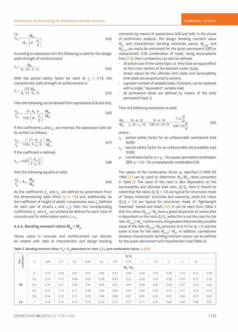
4.2.4. Bending moment ratios MEk / MEd
Stress ratios in concrete and reinforcement can directly be related with ratio of characteristic and design bending
moments by means of expressions (40) and (49). In the phase of preliminary analysis, the design bending moment value MEd and characteristic bending moments values MEk,QP and MEk,CA can easily be estimated for the quasi-permanent (QP) or characteristic (CA) combination of loads. Using assumptions from [12], their correlations can also be defined: - all actions are of the same type, i.e. they have an equal effect
on the cross-section of the element under study, - stress values for the ultimate limit state and serviceability
limit state are proportional to actions, - a greater number of variable loads, if present, can be replaced
with a single, "equivalent" variable load, - all permanent loads are defined by means of the total
permanent load, G.
Then the following expression is valid:
MM
G QG Q
G QG Q
QGQG
Ek
Ed G Q
=+ ⋅
⋅ + ⋅=
+ ⋅⋅ + ⋅
=+
+
ψγ γ
ψ ψ
135 15
1
135 15, , , , (50)
where:gG - partial safety factor for an unfavourable permanent load
(GSN)gQ - partial safety factor for an unfavourable serviceability load
(GSN)y - combination factor: y = y2 - for a quasi-permanent combination
(QP), y = 1,0 – for a characteristic combination (CA).
The values of the combination factor y2 specified in HRN EN 1990 [1] can be used to determine MEk/MEd ratios presented in Table 3. The value of the ratio is also dependent on the serviceability and ultimate load ratio, Qk/Gk. Here it should be noted that the ratios Qk/Gk < 1,0 are typical for structures made of "heavy materials" (concrete and masonry), while the ratios Qk/Gk > 1,0 are typical for structures made of "lightweight materials" (wood and steel) [12]. It can be seen from Table 3 that the ratios MEk,QP/ MEd have a great dispersion of values that is dependent on the ratio Qk/Gk, while this is not the case for the ratio MEk,CA/ MEd. Furthermore, the greatest theoretically possible value of the ratio MEk,QP/ MEd amounts to 0,74 for Qk = 0, and the same is true for the ratio MEk,CA/ MEd. In addition, correlations between characteristic bending moment values can be defined for the quasi-permanent and characteristic load (Table 4).
Load
co
mbi
natio
n
y
Qk/Gk
0.05 0.1 0.2 0.33 0.4 0.5 0.75 1 1.5 2 4 10
MEk/ MEd
QP
0 0.74 0.70 0.67 0.61 0.54 0.51 0.48 0.40 0.35 0.28 0.23 0.14 0.06
0.2 0.74 0.71 0.68 0.63 0.58 0.55 0.52 0.46 0.42 0.36 0.32 0.24 0.18
0.3 0.74 0.71 0.69 0.64 0.60 0.57 0.55 0.49 0.46 0.40 0.37 0.30 0.24
0.6 0.74 0.72 0.71 0.68 0.65 0.64 0.62 0.59 0.56 0.53 0.51 0.46 0.43
0.8 0.74 0.73 0.72 0.70 0.69 0.68 0.67 0.65 0.63 0.61 0.60 0.57 0.55
CA 1 0.74 0.74 0.73 0.73 0.72 0.72 0.71 0.71 0.70 0.69 0.69 0.68 0.67
Table 3. Bending moment ratios MEk/ MEddependent on ratio Qk/Gk and combination factor y, [12]

Građevinar 12/2014
1134
Tomislav Kišiček, Ivan Petrić
GRAĐEVINAR 66 (2014) 12, 1125-1143
Finally, expressions (40) and (49) and stress limitation requirements from expressions (7) to (10) can be used to associate the bending moment ratio MEk/ MEd with each coefficient ksc and kss, depending on the load combination under study. Then the following is valid for the limitation of stress in concrete for the quasi-permanent combination (QP):
σσ
c
ckc
Ek,QP
Edfk
MM
= ⋅ = 0 45, (51)
i.e.:
MM kEk,QP
Ed c
=0 45,
σ (52)
In this way, the pair of strains ec and es1, and all previously defined parameters that are related to them, are associated to each bending moment ratio MEk/ MEd, regarded as an input parameter.
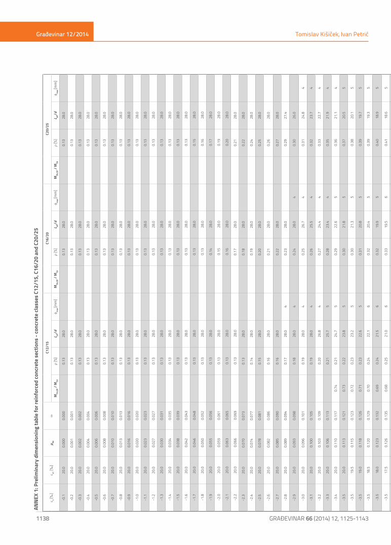
4.3. Final form of preliminary dimensioning tables
Tables for preliminary dimensioning of reinforced-concrete elements according to the ultimate limit state and serviceability limit state are presented in Appendix 1 for concrete classes up to C50/60. An extensive analysis of the use of preliminary dimensioning tables was conducted in [13], and it was concluded that the usability of these tables decreases with an increase in concrete class. That is why these tables are not presented in this paper. The presented tables show that the top limit given in the table for each concrete class is determined with the theoretically greatest possible bending moment ratio, MEk,QP/ MEd = 0.74. However, due to procedure for using the tables (as described in Section 5), the tables start, in their final form, with the minimum value of the dimensionless bending moment mRd. The bottom limit of the table is determined by the boundary condition: MEd ≤ 1.5×MRd,lim.The following is comprised in preliminary dimensioning tables for each bending moment ratio MEk,QP/ MEd: 1) meeting the ultimate limit state requirement through selection of an appropriate tensile reinforcement ratio r, 2) meeting the serviceability limit state (ultimate state of deflection) requirement through selection of the corresponding maximum allowable slenderness
Leff/d, limit state of cracking, by making sure that the greatest steel bar diameter does not exceed the value given in table and the ultimate limit state. For the quasi-permanent combination of actions, the stress limitation in reinforcement is ensured through the maximum allowable bar diameter for the cracking limit state, while the stress limitation in concrete is ensured through a relation according to expression (52). For the characteristic combination of actions, the stress limitation in concrete according to expression (9) is ensured by the fact that, for the maximum theoretically possible moment ratio, MEk,CA/ MEd = 0,74, and the greatest coefficient kss = 0,96, and the class C90/105, the stress ratio in reinforcement and steel yield limit ratio amount to:
σ s1 yk/ , , , ,f = ⋅ = <0 96 0 74 0 71 0 80 (53)
which makes the verification of stress in reinforcement for characteristic combination quite unnecessary [12]. In addition, as the stress in reinforcement rarely exceeds the value of 310 N/mm2, it is not necessary to reduce the limit slenderness values from the table, based on expression (3). Consequently, the limit slenderness values are on the side of safety for all stresses in the reinforcement.For the typical combination of actions, the limitation of stress in concrete is ensured in the following way:Preliminary dimensioning tables are based on the limitation of stress in concrete based on the quasi-permanent (QP) combination, according to expression (8), which amounts to 75% of the stress allowed according to the characteristic (CA) combination of actions:
σ
σc ck QP
c ck CA
//
,,
,ff
( )( )
= =0 450 60
0 75 (54)
According to Table 4, typical bending moment ratios, MEk,QP/ MEk,CA, are generally greater than 0.75 (marked in blue colour) for structures made of "heavy" materials (concrete, walls). However, if MEk,QP/ MEk,CA < 0,75 then the characteristic combination (CA) is relevant for calculation. To ensure limitation of stress according to expression (7), the preliminary dimensioning can start with the following ratio:
Table 4. Bending moment ratiosMEk,QP/ MEk,CA dependent on ratio Qk/Gk and combination factor y, [12]
Load
co
mbi
natio
n
y
Qk/Gk
0.05 0.1 0.2 0.33 0.4 0.5 0.75 1 1.5 2 4 10
MEk.QP/ MEk.CA
QP
0 1.00 0.95 0.91 0.83 0.75 0.71 0.67 0.57 0.50 0.40 0.33 0.20 0.09
0.2 1.00 0.96 0.93 0.87 0.80 0.77 0.73 0.66 0.60 0.52 0.47 0.36 0.27
0.3 1.00 0.97 0.94 0.88 0.83 0.80 0.77 0.70 0.65 0.58 0.53 0.44 0.36
0.6 1.00 0.98 0.96 0.93 0.90 0.89 0.87 0.83 0.80 0.76 0.73 0.68 0.64
0.8 1.00 0.99 0.98 0.97 0.95 0.94 0.93 0.91 0.90 0.88 0.87 0.84 0.82
CA 1 1.00 1.00 1.00 1.00 1.00 1.00 1.00 1.00 1.00 1.00 1.00 1.00 1.00
Građevinar 12/2014
1135GRAĐEVINAR 66 (2014) 12, 1125-1143
Preliminary dimensioning of reinforced concrete sections
ec [‰]
es1 [‰] µRd w MEk,QP/ MEd
r[%] Leff/d φmax
[mm]
-3.5 6.5 0.242 0.283 0.57 1.30 14.5 16
-3.5 6.0 0.253 0.298 0.56 1.37 14.3 18
-3.5 5.5 0.264 0.315 0.54 1.45 14.1 19
-3.5 5.0 0.276 0.333 0.52 1.53 13.9 21
-3.5 4.5 0.290 0.354 0.51 1.63 13.8 23
MM
MM
Ek,QP
Ed
Ek,CA
Ed
= ⋅0 75, (55)
which is greater than the real ratio MEk,QP/ MEd, but which ensures that all registered values are on the side of safety [12].
5. Use of preliminary dimensioning tables
5.1. Beams
This Section presents the procedure for using preliminary dimensioning tables on a real-life design assignment, and the comparison of the results obtained with those obtained by detailed calculation of the beam according to the serviceability limit state.
5.1.1. Task
It is necessary to determine the smallest required effective depth of the simply supported continuously loaded reinforced-concrete T-beam, and the quantity of steel reinforcement required to meet the ultimate limit state and serviceability limit state requirements. The beam is made of concrete C30/37. The beam span is L = 400 cm, the flange thickness is hf = 15 cm, the effective flange width is beff = 120 cm, and the web width is bw = 25 cm. The maximum bending moments in the span of the beam are MG = 100 kNm, MQ = 55 kNm while y2 = 0,3.
The beam calculation procedure using dimensioning tables must be conducted as follows:
1) determine permanent load G, and variable load Q, for the element under study based on the corresponding area from which the element assumes the load (the self-weight of the slab above the beam must also be taken into account). In this particular case, the slab weight is included in the bending moment from permanent load MG, but the beam (web) self-weight is not taken into account in the first determination of moment ratios, because the beam height is not known. After determination of the beam height, the entire calculation can be repeated with a more accurate self-weight, but this procedure converges quite rapidly, especially in case of higher loads where the part of the beam web weight in the total load is small.
2) determine bending moments, MEk,QP i MEd, for the "normalised"
span Ln independent of the type of static system
M g LG
n=⋅ 2
8 ; M q LQ
n=⋅ 2
8
In this concrete case, bending moment values are set as an input data, and so we have:
M M MEk,QP G Q kNm= + ⋅ = + ⋅ =ψ 2 100 0 3 55 116 5, ,
M M MEd G Q kNm= ⋅ + ⋅ = ⋅ + ⋅ =135 15 135 100 15 55 217 5, , , , ,
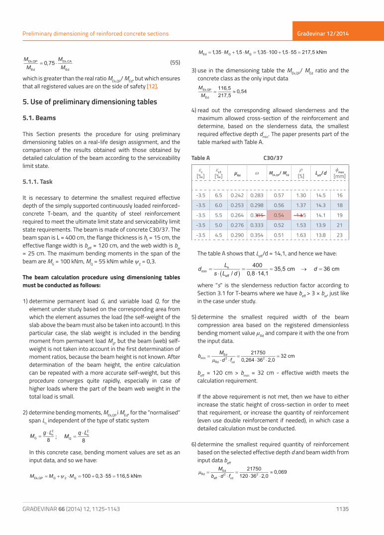
3) use in the dimensioning table the MEk,QP/ MEd ratio and the concrete class as the only input data
MMEk,QP
Ed
= ≈116 5217 5
0 54,,
,
4) read out the corresponding allowed slenderness and the maximum allowed cross-section of the reinforcement and determine, based on the slenderness data, the smallest required effective depth dmin. The paper presents part of the table marked with Table A.
Table A C30/37
The table A shows that Leff/d = 14,1, and hence we have:
d Ls L d
dminn
eff
cm cm=⋅ ( )
=⋅
= → =/ , ,
,4000 8 14 1
35 5 36 where "s" is the slenderness reduction factor according to
Section 3.1 for T-beams where we have beff > 3 × bw, just like in the case under study.
5) determine the smallest required width of the beam compression area based on the registered dimensionless bending moment value mRd and compare it with the one from the input data.
b Md fminEd
Rd cd
cm=⋅ ⋅
=⋅ ⋅
=µ 2 2
217500 264 36 2 0
32, ,
beff = 120 cm > bmin = 32 cm - effective width meets the
calculation requirement.
If the above requirement is not met, then we have to either increase the static height of cross-section in order to meet that requirement, or increase the quantity of reinforcement (even use double reinforcement if needed), in which case a detailed calculation must be conducted.
6) determine the smallest required quantity of reinforcement based on the selected effective depth d and beam width from input data beff
µRd
Ed
eff cd
=⋅ ⋅
=⋅ ⋅
≈M
b d f2 221750
120 36 2 00 069
,,
← →

Građevinar 12/2014
1136
Tomislav Kišiček, Ivan Petrić
GRAĐEVINAR 66 (2014) 12, 1125-1143
Register the part of tensile reinforcement r ( %) for the first value equal to or greater than mRd The paper presents part of the table marked with Table B.
From the Table B was registered:r = 0,34 % = 0,0034:
Table B C30/37
As,1 = r·beff · d = 0,0034 · 120 · 36 = 14,69 cm2
In case the first equal to or greater than dimensionless bending moment mRd is situated in the double reinforcement zone, i.e. if the relation mRd > mRd,lim is valid, then the cross-section requires double reinforcement, and the calculation of elements can not be conducted based on preliminary dimensioning tables.The following values were obtained through preliminary calculation: effective depth of the beam: d = 36 cm, tensile reinforcement area: As1 = 14,69 cm2, while the following reinforcement diameter was selected: φ16. According to the selected element dimensions, and the type and quality of reinforcement, the beam meats the ultimate limit state as well as the serviceability limit state requirements.
5.1.2. Verification of results
Preliminary calculation results from the preceding section were verified using a detailed procedure for calculating beams with regard to serviceability limit state, conducted according to the following lecture notes [6]. Only the final results are given as the procedure is quite extensive.
Ultimate limit state- required quantity of reinforcement
As1,req = 14,48 cm2 < As1,prov = 14,69 cm2 → satisfactory
Serviceability limit state- crack width for short-term action:
wk,t=0 = 0,17 mm < wmax = 0,3 mm → satisfactory
- crack width for long-term action
wk,t=∞ = 0,13 mm < wmax = 0,3 mm → satisfactory
- total deflection from short-term action: vtot,t=0 = 0,87 cm < vlim = L / 250 = 400 / 250 = 1,6 cm →
satisfactory
- total deflection from long-term action vtot,t=∞ = 1,05 cm < vlim = L / 250 = 400 / 250 = 1,6 cm → satisfactory
A more detailed analysis of preliminary calculation results is presented in [13]. A number of reinforced-concrete beams with the corresponding input data was set, just like in the task described in Section 5.1.1. It was established by detailed calculation that all results comply with ultimate limit state and serviceability limit state requirements. In addition, a minimum required effective depth and the corresponding reinforcement was defined for the same input data through detailed calculation. The comparison shows that deviation does exist, just like in the preceding example, but the differences are significantly smaller in case of rectangular section beams and T-beams where beff ≤ 3 · bw is valid. This is due to the reduction factor that is not taken into account in such cases.In case of T-beams where beff ≤ 3 · bw is valid, the sections with effective depths that are about 30% higher than the minimum ones are obtained by means of tables. However, this also implies the need for much lower quantity of reinforcement (25 % on an average). When using tables for such cross-sections, care should be taken about deviations, so that an excessive total weight of structure is not obtained during preliminary calculations. Later on, during the conduct of detailed calculations, economic and aesthetic parameters have to be taken into account for selection of final dimensions and reinforcement of elements.In case of T-beams where beff ≤ 3 · bw is valid, and in case of the rectangular cross-section, the sections with lower or no deviation from the required minimums is realized, with a possibly somewhat higher quantity of reinforcement compared to the minimum reinforcement needed to meet the ultimate limit state requirements.
5.1. Slabs
As mentioned in Section 3.2, special measures are not needed for limiting crack width of reinforced-concrete slabs up to 20 cm in thickness, which are subjected to bending stress without a significant longitudinal axial tension. At that, the greatest spacing between the main reinforcing bars and distribution bars (amounting to no less than 20 % of the main reinforcement) should not exceed values specified in Section 9.2.1.1 of HRN EN 1992-1-1 [3] or Section 5.5.1 from [5].Therefore, when a slab is dimensioned with regard to serviceability limit state requirements, its height must be defined exclusively on the basis of deformation (deflection) control/check, except in case of slender slabs (slabs on point supports) where the control of the punching shear [11] may be more relevant for dimensioning. In addition, long-term impacts on concrete should also be taken into account.
ec [‰]
es1 [‰] µRd w MEk,QP/ MEd
r [%] Leff/d φmax
[mm]
-2.1 20.0 0.063 0.065 0.30 28.0
-2.2 20.0 0.066 0.069 0.32 28.0
-2.3 20.0 0.070 0.073 → 0.34 28.0
-2.4 20.0 0.074 0.077 0.36 28.0
-2.5 20.0 0.078 0.081 0.37 28.0

Građevinar 12/2014
1137GRAĐEVINAR 66 (2014) 12, 1125-1143
Preliminary dimensioning of reinforced concrete sections
Accordingly, the use of tables for the preliminary dimensioning of slabs, to take into account stress control for meeting the cracking limit state requirements, provides results that are significantly on the side of safety, which results in slab heights that are not economical. Thus, tables for preliminary dimensioning, as described in this paper, are not applicable for the dimensioning of reinforced-concrete slabs.
6. Conclusion
During the design of reinforced-concrete structures in the early phases of projects, it is often necessary to make the preliminary dimensioning of structural elements. This is particularly important in case of complex structures in order to determine preliminary basic dimensions of elements that can be used during subsequent detailed calculations.This paper describes the procedure for preparing tables, and the use of such tables in the dimensioning of reinforced-concrete beams of various cross-sections, according to the ultimate limit state and serviceability limit state requirements, as per HRN EN 1990 [1] and HRN EN 1992-1-1 [3]. The tables for concrete classes of up to C50/60 are presented. An extensive analysis of the use of tables for preliminary dimensioning is conducted in the paper [13] and it was established that
the applicability of these tables decreases with an increase in concrete class. That is why tables for higher classes of concrete are not presented in this paper.As proven in examples by means of appropriate results, the beams dimensioned according to tables meet ultimate limit state and serviceability limit state requirements. Deviations of results from the ones obtained in detailed calculations are small for rectangular beams and T-beams whose flange width does not exceed three web widths. Deviations are greater for T-beams in which the flange width is greater. In case of reinforced-concrete slabs, the tables provide results that are considerably on the side of safety, and so the tables are not applicable for such slabs.In general terms, the cause of deviation of results lies in the need to fulfil basic conservative requirements for individual serviceability limit states, as this eliminates the need for detailed calculation.However, deviations can be accepted as satisfactory if we consider that this is a preliminary dimensioning stage, and that the subsequent detailed calculation is indispensable. Furthermore, these preliminary dimensioning tables enable designers to avoid the "trial and error" approach during calculation of elements of unknown dimensions, and to make good use of a fast and simple preliminary analysis in case of a small number of input data.
REFERENCES[1] HRN EN 1990:2011, Eurokod: Osnove projektiranja konstrukcija,
Eurocode: Basis of structural design. European Committee for Standardization, Brussels
[2] HRN EN 1991-1-1:2012, Eurokod 1: Djelovanja na konstrukcije – Dio 1-1: Opća djelovanja – Obujamske težine, vlastite težine i uporabna opterećenja za zgrade, Eurocode 1: Actions on structures – Part 1-1: General actions – Densities, self-weight, imposed loads for buildings. European Committee for Standardization, Bruxelles
[3] HRN EN 1992-1-1:2013, Eurokod 2: Projektiranje betonskih konstrukcija – Dio 1-1: Opća pravila i pravila za zgrade, Eurocode 2: Design of concrete structures – Part 1-1: General rules and rules for buildings, European Committee for Standardization, Bruxelles
[4] Kišiček, T.: Sorić, Z., Galić, J.: Tablice za dimenzioniranje armiranobetonskih presjeka, Građevinar 62 (2010) 11, pp. 1001-1010.
[5] Sorić, Z., Kišiček T.: Betonske konstrukcije 1, Skripta Građevinskog fakulteta, Zagreb, 2011.
[6] Sorić, Z., Kišiček T., Betonske konstrukcije 2, Skripta Građevinskog fakulteta, Zagreb, 2012.
[7] Institution of Structural Engineers, Manual for the design of reinforced concrete building structures to EC2, London, March 2000.
[8] Tomičić, I.: Betonske konstrukcije, DHGK, Zagreb, 1996.[9] Eurocode 2 – Commentary, European Concrete Platform ASBL,
Bruxelles, June 2008[10] HRN EN 1992-1-1:2013/NA:2013, Eurokod 2: Projektiranje
betonskih konstrukcija – Dio 1-1: Opća pravila i pravila za zgrade – Nacionalni dodatak, Eurocode 2: Design of concrete structures – Part 1-1: General rules and rules for buildings, National Annex
[11] Biasioli, F., Mancini G.: Eurocode 2 – Worked example, Bruxelles, 2011
[12] Biasioli, F.: Progetto agli stati limite degli elementi inflessi, un approccio olistico, Dipartimento di Ingegneria Strutturale e Geotecnica, Politecnico di Torino, 2011.
[13] Petrić, I.: Tablice za preliminarno dimenzioniranje armiranobetonskih presjeka, diplomski rad, Građevinski fakultet Sveučilišta u Zagrebu, 2012.
[14] HRN EN 1990:2011/NA2011, Eurokod: Osnove projektiranja konstrukcija, Eurocode: Basis of structural design – National Annex
[15] HRN EN 1991-1-1:2012/NA:2012, Eurokod 1: Djelovanja na konstrukcije – Dio 1-1: Opća djelovanja – Obujamske težine, vlastite težine i uporabna opterećenja za zgrade – Nacionalni dodatak, Eurocode 1: Actions on Structures – Part 1-1: General actions – Densities, self-weight, imposed loads for buildings – National Annex
Građevinar 12/2014
1138
Tomislav Kišiček, Ivan Petrić
GRAĐEVINAR 66 (2014) 12, 1125-1143
e c [‰]
e s1 [‰
]µ Rd
wC1
2/15
C16/
20C2
0/25
MEk
,QP /
MEd
r [%
]L ef
f/dφ m
ax [m
m]
MEk
,QP /
MEd
r [%
]L ef
f/dφ m
ax [m
m]
MEk
,QP /
MEd
r [%
]L ef
f/dφ m
ax [m
m]
-0.1
20.0
0.00
00.
000
0.
1328
.0
0.
1328
.0
0.
1328
.0
-0.2
20.0
0.00
10.
001
0.
1328
.0
0.
1328
.0
0.
1328
.0
-0.3
20.0
0.00
20.
002
0.
1328
.0
0.
1328
.0
0.
1328
.0
-0.4
20.0
0.00
40.
004
0.
1328
.0
0.
1328
.0
0.
1328
.0
-0.5
20.0
0.00
60.
006
0.
1328
.0
0.
1328
.0
0.
1328
.0
-0.6
20.0
0.00
80.
008
0.
1328
.0
0.
1328
.0
0.
1328
.0
-0.7
20.0
0.01
00.
010
0.
1328
.0
0.
1328
.0
0.
1328
.0
-0.8
20.0
0.01
30.
013
0.
1328
.0
0.
1328
.0
0.
1328
.0
-0.9
20.0
0.01
60.
016
0.
1328
.0
0.
1328
.0
0.
1328
.0
-1.0
20.0
0.02
00.
020
0.
1328
.0
0.
1328
.0
0.
1328
.0
-1.1
20.0
0.02
30.
023
0.
1328
.0
0.
1328
.0
0.
1328
.0
-1.2
20.0
0.02
70.
027
0.
1328
.0
0.
1328
.0
0.
1328
.0
-1.3
20.0
0.03
00.
031
0.
1328
.0
0.
1328
.0
0.
1328
.0
-1.4
20.0
0.03
40.
035
0.
1328
.0
0.
1328
.0
0.
1328
.0
-1.5
20.0
0.03
80.
039
0.
1328
.0
0.
1328
.0
0.
1328
.0
-1.6
20.0
0.04
20.
043
0.
1328
.0
0.
1328
.0
0.
1328
.0
-1.7
20.0
0.04
60.
048
0.
1328
.0
0.
1328
.0
0.
1528
.0
-1.8
20.0
0.05
00.
052
0.
1328
.0
0.
1328
.0
0.
1628
.0
-1.9
20.0
0.05
50.
056
0.
1328
.0
0.
1428
.0
0.
1728
.0
-2.0
20.0
0.05
90.
061
0.
1328
.0
0.
1528
.0
0.
1928
.0
-2.1
20.0
0.06
30.
065
0.
1328
.0
0.
1628
.0
0.
2028
.0
-2.2
20.0
0.06
60.
069
0.
1328
.0
0.
1728
.0
0.
2128
.0
-2.3
20.0
0.07
00.
073
0.
1328
.0
0.
1828
.0
0.
2228
.0
-2.4
20.0
0.07
40.
077
0.
1428
.0
0.19
28.0
0.24
28.0
-2.5
20.0
0.07
80.
081
0.
1528
.0
0.20
28.0
0.
2528
.0
-2.6
20.0
0.08
20.
086
0.
1628
.0
0.21
28.0
0.
2628
.0
-2.7
20.0
0.08
50.
090
0.
1628
.0
0.22
28.0
0.
2728
.0
-2.8
20.0
0.08
90.
094
0.
1728
.04
0.
2328
.0
0.29
27.4
-2.9
20.0
0.09
30.
098
0.
1828
.04
0.
2428
.04
0.
3026
.0
-3.0
20.0
0.09
60.
101
0.
1928
.04
0.
2526
.74
0.
3124
.84
-3.1
20.0
0.10
00.
105
0.
1928
.04
0.
2625
.54
0.
3223
.74
-3.2
20.0
0.10
30.
109
0.
2026
.84
0.
2724
.44
0.
3322
.74
-3.3
20.0
0.10
60.
113
0.
2125
.75
0.
2823
.44
0.
3521
.94
-3.4
20.0
0.11
00.
117
0.74
0.21
24.7
5
0.29
22.6
5
0.36
21.1
4
-3.5
20.0
0.11
30.
121
0.73
0.22
23.8
5
0.30
21.8
5
0.37
20.5
5
-3.5
19.5
0.11
50.
123
0.72
0.23
23.2
5
0.30
21.3
5
0.38
20.1
5
-3.5
19.0
0.11
80.
126
0.71
0.23
22.6
5
0.31
20.8
5
0.39
19.7
5
-3.5
18.5
0.12
00.
129
0.70
0.24
22.1
6
0.32
20.4
5
0.39
19.3
5
-3.5
18.0
0.12
30.
132
0.69
0.24
21.5
6
0.32
19.9
5
0.40
18.9
5
-3.5
17.5
0.12
60.
135
0.68
0.25
21.0
6
0.33
19.5
6
0.41
18.6
5
-3.5
17.0
0.12
80.
138
0.68
0.25
20.5
60.
740.
3419
.16
0.
4218
.36
-3.5
16.5
0.13
10.
142
0.67
0.26
20.0
60.
730.
3518
.76
0.
4318
.06
-3.5
16.0
0.13
40.
145
0.66
0.27
19.5
70.
720.
3618
.36
0.
4517
.76
-3.5
15.5
0.13
80.
149
0.65
0.27
19.1
70.
710.
3717
.96
0.
4617
.66
-3.5
15.0
0.14
10.
153
0.64
0.28
18.6
70.
690.
3817
.67
0.74
0.47
17.4
7
-3.5
14.5
0.14
50.
157
0.63
0.29
18.2
70.
680.
3917
.37
0.73
0.48
17.2
7
-3.5
14.0
0.14
80.
162
0.62
0.30
17.8
80.
670.
4017
.07
0.72
0.50
17.0
7
-3.5
13.5
0.15
20.
167
0.61
0.31
17.4
80.
660.
4116
.98
0.70
0.51
16.9
7
-3.5
13.0
0.15
70.
172
0.60
0.32
17.0
80.
650.
4216
.78
0.69
0.53
16.7
8
-3.5
12.5
0.16
10.
177
0.59
0.33
16.7
90.
640.
4316
.58
0.68
0.54
16.5
8
-3.5
12.0
0.16
60.
183
0.58
0.34
16.4
90.
630.
4516
.49
0.67
0.56
16.4
9
-3.5
11.5
0.17
10.
189
0.57
0.35
16.2
90.
620.
4616
.29
0.66
0.58
16.2
9
-3.5
11.0
0.17
60.
195
0.56
0.36
16.0
100.
610.
4816
.09
0.64
0.60
16.0
9
-3.5
10.5
0.18
10.
202
0.55
0.37
15.8
100.
600.
5015
.810
0.63
0.62
15.8
10
-3.5
10.0
0.18
70.
210
0.54
0.39
15.7
110.
580.
5115
.710
0.62
0.64
15.7
10
-3.5
9.5
0.19
40.
218
0.53
0.40
15.5
110.
570.
5315
.511
0.61
0.67
15.5
11
-3.5
9.0
0.20
00.
227
0.52
0.42
15.3
120.
560.
5615
.312
0.59
0.70
15.3
12
-3.5
8.5
0.20
70.
236
0.51
0.43
15.1
130.
550.
5815
.112
0.58
0.72
15.1
12
-3.5
8.0
0.21
50.
246
0.50
0.45
15.0
130.
540.
6015
.013
0.57
0.76
15.0
13
-3.5
7.5
0.22
30.
258
0.48
0.47
14.8
140.
520.
6314
.814
0.55
0.79
14.8
14
-3.5
7.0
0.23
20.
270
0.47
0.50
14.6
150.
510.
6614
.615
0.54
0.83
14.6
15
-3.5
6.5
0.24
20.
283
0.46
0.52
14.5
160.
500.
7014
.516
0.52
0.87
14.5
16
-3.5
6.0
0.25
30.
298
0.45
0.55
14.3
170.
480.
7314
.317
0.51
0.91
14.3
17
-3.5
5.5
0.26
40.
315
0.44
0.58
14.1
190.
470.
7714
.118
0.50
0.97
14.1
19
-3.5
5.0
0.27
60.
333
0.43
0.61
13.9
200.
460.
8213
.920
0.48
1.02
13.9
20
-3.5
4.5
0.29
00.
354
0.41
0.65
13.8
220.
440.
8713
.822
0.47
1.09
13.8
22
-3.5
4.3
0.29
60.
364
0.41
0.67
13.7
230.
440.
8913
.723
0.46
1.12
13.7
23
-3.5
4.0
0.30
40.
378
0.40
0.70
13.6
240.
430.
9313
.624
0.45
1.16
13.6
24
-3.5
3.8
0.31
10.
388
0.40
0.71
13.5
250.
430.
9513
.525
0.45
1.19
13.5
25
-3.5
3.6
0.31
70.
399
0.39
0.73
13.5
250.
420.
9813
.526
0.44
1.22
13.5
26
-3.5
3.4
0.32
40.
411
0.39
0.76
13.4
250.
411.
0113
.427
0.44
1.26
13.4
27
-3.5
3.2
0.33
10.
423
0.38
0.78
13.3
250.
411.
0413
.328
0.43
1.30
13.3
29
-3.5
3.0
0.33
80.
436
0.38
0.80
13.2
250.
401.
0713
.229
0.42
1.34
13.2
30
-3.5
2.8
0.34
60.
450
0.37
0.83
13.2
250.
401.
1013
.230
0.42
1.38
13.2
31
-3.5
2.6
0.35
40.
464
0.37
0.85
13.1
250.
391.
1413
.130
0.41
1.42
13.1
33
-3.5
2.4
0.36
20.
480
0.36
0.88
13.0
250.
391.
1813
.030
0.41
1.47
13.0
34
-3.5
2.2
0.37
00.
497
0.36
0.91
13.0
250.
381.
2213
.030
0.40
1.52
13.0
35
-3.5
2.0
0.37
90.
515
0.35
0.95
12.9
250.
381.
2612
.930
0.39
1.58
12.9
35
-3.5
1.8
0.38
80.
535
0.35
0.98
12.8
250.
371.
3112
.830
0.39
1.64
12.8
35
-3.5
1.6
0.39
70.
556
0.34
1.02
12.8
250.
371.
3612
.830
0.38
1.70
12.8
35
-3.5
1.4
0.40
60.
578
0.34
1.06
12.7
250.
361.
4212
.730
0.38
1.77
12.7
35
-3.5
1.2
0.41
60.
603
0.34
1.11
12.6
250.
361.
4812
.630
0.37
1.85
12.6
35
-3.5
1.0
0.42
60.
630
0.33
1.16
12.6
250.
351.
5412
.630
0.37
1.93
12.6
35
-3.5
0.8
0.43
60.
659
0.33
1.21
12.5
250.
351.
6212
.530
0.36
2.02
12.5
35
ANN
EX 1
: Pre
limin
ary
dim
ensi
onin
g ta
ble
for r
einf
orce
d co
ncre
te s
ectio
ns -
conc
rete
clas
ses
C12/
15, C
16/2
0 an
d C2
0/25

Građevinar 12/2014
1139
Preliminary dimensioning of reinforced concrete sections
GRAĐEVINAR 66 (2014) 12, 1125-1143
e c [‰]
e s1 [‰
]µ Rd
wC1
2/15
C16/
20C2
0/25
MEk
,QP /
MEd
r [%
]L ef
f/dφ m
ax [m
m]
MEk
,QP /
MEd
r [%
]L ef
f/dφ m
ax [m
m]
MEk
,QP /
MEd
r [%
]L ef
f/dφ m
ax [m
m]
-0.1
20.0
0.00
00.
000
0.
1328
.0
0.
1328
.0
0.
1328
.0
-0.2
20.0
0.00
10.
001
0.
1328
.0
0.
1328
.0
0.
1328
.0
-0.3
20.0
0.00
20.
002
0.
1328
.0
0.
1328
.0
0.
1328
.0
-0.4
20.0
0.00
40.
004
0.
1328
.0
0.
1328
.0
0.
1328
.0
-0.5
20.0
0.00
60.
006
0.
1328
.0
0.
1328
.0
0.
1328
.0
-0.6
20.0
0.00
80.
008
0.
1328
.0
0.
1328
.0
0.
1328
.0
-0.7
20.0
0.01
00.
010
0.
1328
.0
0.
1328
.0
0.
1328
.0
-0.8
20.0
0.01
30.
013
0.
1328
.0
0.
1328
.0
0.
1328
.0
-0.9
20.0
0.01
60.
016
0.
1328
.0
0.
1328
.0
0.
1328
.0
-1.0
20.0
0.02
00.
020
0.
1328
.0
0.
1328
.0
0.
1328
.0
-1.1
20.0
0.02
30.
023
0.
1328
.0
0.
1328
.0
0.
1328
.0
-1.2
20.0
0.02
70.
027
0.
1328
.0
0.
1328
.0
0.
1328
.0
-1.3
20.0
0.03
00.
031
0.
1328
.0
0.
1328
.0
0.
1328
.0
-1.4
20.0
0.03
40.
035
0.
1328
.0
0.
1328
.0
0.
1328
.0
-1.5
20.0
0.03
80.
039
0.
1328
.0
0.
1328
.0
0.
1328
.0
-1.6
20.0
0.04
20.
043
0.
1328
.0
0.
1328
.0
0.
1328
.0
-1.7
20.0
0.04
60.
048
0.
1328
.0
0.
1328
.0
0.
1528
.0
-1.8
20.0
0.05
00.
052
0.
1328
.0
0.
1328
.0
0.
1628
.0
-1.9
20.0
0.05
50.
056
0.
1328
.0
0.
1428
.0
0.
1728
.0
-2.0
20.0
0.05
90.
061
0.
1328
.0
0.
1528
.0
0.
1928
.0
-2.1
20.0
0.06
30.
065
0.
1328
.0
0.
1628
.0
0.
2028
.0
-2.2
20.0
0.06
60.
069
0.
1328
.0
0.
1728
.0
0.
2128
.0
-2.3
20.0
0.07
00.
073
0.
1328
.0
0.
1828
.0
0.
2228
.0
-2.4
20.0
0.07
40.
077
0.
1428
.0
0.19
28.0
0.24
28.0
-2.5
20.0
0.07
80.
081
0.
1528
.0
0.20
28.0
0.
2528
.0
-2.6
20.0
0.08
20.
086
0.
1628
.0
0.21
28.0
0.
2628
.0
-2.7
20.0
0.08
50.
090
0.
1628
.0
0.22
28.0
0.
2728
.0
-2.8
20.0
0.08
90.
094
0.
1728
.04
0.
2328
.0
0.29
27.4
-2.9
20.0
0.09
30.
098
0.
1828
.04
0.
2428
.04
0.
3026
.0
-3.0
20.0
0.09
60.
101
0.
1928
.04
0.
2526
.74
0.
3124
.84
-3.1
20.0
0.10
00.
105
0.
1928
.04
0.
2625
.54
0.
3223
.74
-3.2
20.0
0.10
30.
109
0.
2026
.84
0.
2724
.44
0.
3322
.74
-3.3
20.0
0.10
60.
113
0.
2125
.75
0.
2823
.44
0.
3521
.94
-3.4
20.0
0.11
00.
117
0.74
0.21
24.7
5
0.29
22.6
5
0.36
21.1
4
-3.5
20.0
0.11
30.
121
0.73
0.22
23.8
5
0.30
21.8
5
0.37
20.5
5
-3.5
19.5
0.11
50.
123
0.72
0.23
23.2
5
0.30
21.3
5
0.38
20.1
5
-3.5
19.0
0.11
80.
126
0.71
0.23
22.6
5
0.31
20.8
5
0.39
19.7
5
-3.5
18.5
0.12
00.
129
0.70
0.24
22.1
6
0.32
20.4
5
0.39
19.3
5
-3.5
18.0
0.12
30.
132
0.69
0.24
21.5
6
0.32
19.9
5
0.40
18.9
5
-3.5
17.5
0.12
60.
135
0.68
0.25
21.0
6
0.33
19.5
6
0.41
18.6
5
-3.5
17.0
0.12
80.
138
0.68
0.25
20.5
60.
740.
3419
.16
0.
4218
.36
-3.5
16.5
0.13
10.
142
0.67
0.26
20.0
60.
730.
3518
.76
0.
4318
.06
-3.5
16.0
0.13
40.
145
0.66
0.27
19.5
70.
720.
3618
.36
0.
4517
.76
-3.5
15.5
0.13
80.
149
0.65
0.27
19.1
70.
710.
3717
.96
0.
4617
.66
-3.5
15.0
0.14
10.
153
0.64
0.28
18.6
70.
690.
3817
.67
0.74
0.47
17.4
7
-3.5
14.5
0.14
50.
157
0.63
0.29
18.2
70.
680.
3917
.37
0.73
0.48
17.2
7
-3.5
14.0
0.14
80.
162
0.62
0.30
17.8
80.
670.
4017
.07
0.72
0.50
17.0
7
-3.5
13.5
0.15
20.
167
0.61
0.31
17.4
80.
660.
4116
.98
0.70
0.51
16.9
7
-3.5
13.0
0.15
70.
172
0.60
0.32
17.0
80.
650.
4216
.78
0.69
0.53
16.7
8
-3.5
12.5
0.16
10.
177
0.59
0.33
16.7
90.
640.
4316
.58
0.68
0.54
16.5
8
-3.5
12.0
0.16
60.
183
0.58
0.34
16.4
90.
630.
4516
.49
0.67
0.56
16.4
9
-3.5
11.5
0.17
10.
189
0.57
0.35
16.2
90.
620.
4616
.29
0.66
0.58
16.2
9
-3.5
11.0
0.17
60.
195
0.56
0.36
16.0
100.
610.
4816
.09
0.64
0.60
16.0
9
-3.5
10.5
0.18
10.
202
0.55
0.37
15.8
100.
600.
5015
.810
0.63
0.62
15.8
10
-3.5
10.0
0.18
70.
210
0.54
0.39
15.7
110.
580.
5115
.710
0.62
0.64
15.7
10
-3.5
9.5
0.19
40.
218
0.53
0.40
15.5
110.
570.
5315
.511
0.61
0.67
15.5
11
-3.5
9.0
0.20
00.
227
0.52
0.42
15.3
120.
560.
5615
.312
0.59
0.70
15.3
12
-3.5
8.5
0.20
70.
236
0.51
0.43
15.1
130.
550.
5815
.112
0.58
0.72
15.1
12
-3.5
8.0
0.21
50.
246
0.50
0.45
15.0
130.
540.
6015
.013
0.57
0.76
15.0
13
-3.5
7.5
0.22
30.
258
0.48
0.47
14.8
140.
520.
6314
.814
0.55
0.79
14.8
14
-3.5
7.0
0.23
20.
270
0.47
0.50
14.6
150.
510.
6614
.615
0.54
0.83
14.6
15
-3.5
6.5
0.24
20.
283
0.46
0.52
14.5
160.
500.
7014
.516
0.52
0.87
14.5
16
-3.5
6.0
0.25
30.
298
0.45
0.55
14.3
170.
480.
7314
.317
0.51
0.91
14.3
17
-3.5
5.5
0.26
40.
315
0.44
0.58
14.1
190.
470.
7714
.118
0.50
0.97
14.1
19
-3.5
5.0
0.27
60.
333
0.43
0.61
13.9
200.
460.
8213
.920
0.48
1.02
13.9
20
-3.5
4.5
0.29
00.
354
0.41
0.65
13.8
220.
440.
8713
.822
0.47
1.09
13.8
22
-3.5
4.3
0.29
60.
364
0.41
0.67
13.7
230.
440.
8913
.723
0.46
1.12
13.7
23
-3.5
4.0
0.30
40.
378
0.40
0.70
13.6
240.
430.
9313
.624
0.45
1.16
13.6
24
-3.5
3.8
0.31
10.
388
0.40
0.71
13.5
250.
430.
9513
.525
0.45
1.19
13.5
25
-3.5
3.6
0.31
70.
399
0.39
0.73
13.5
250.
420.
9813
.526
0.44
1.22
13.5
26
-3.5
3.4
0.32
40.
411
0.39
0.76
13.4
250.
411.
0113
.427
0.44
1.26
13.4
27
-3.5
3.2
0.33
10.
423
0.38
0.78
13.3
250.
411.
0413
.328
0.43
1.30
13.3
29
-3.5
3.0
0.33
80.
436
0.38
0.80
13.2
250.
401.
0713
.229
0.42
1.34
13.2
30
-3.5
2.8
0.34
60.
450
0.37
0.83
13.2
250.
401.
1013
.230
0.42
1.38
13.2
31
-3.5
2.6
0.35
40.
464
0.37
0.85
13.1
250.
391.
1413
.130
0.41
1.42
13.1
33
-3.5
2.4
0.36
20.
480
0.36
0.88
13.0
250.
391.
1813
.030
0.41
1.47
13.0
34
-3.5
2.2
0.37
00.
497
0.36
0.91
13.0
250.
381.
2213
.030
0.40
1.52
13.0
35
-3.5
2.0
0.37
90.
515
0.35
0.95
12.9
250.
381.
2612
.930
0.39
1.58
12.9
35
-3.5
1.8
0.38
80.
535
0.35
0.98
12.8
250.
371.
3112
.830
0.39
1.64
12.8
35
-3.5
1.6
0.39
70.
556
0.34
1.02
12.8
250.
371.
3612
.830
0.38
1.70
12.8
35
-3.5
1.4
0.40
60.
578
0.34
1.06
12.7
250.
361.
4212
.730
0.38
1.77
12.7
35
-3.5
1.2
0.41
60.
603
0.34
1.11
12.6
250.
361.
4812
.630
0.37
1.85
12.6
35
-3.5
1.0
0.42
60.
630
0.33
1.16
12.6
250.
351.
5412
.630
0.37
1.93
12.6
35
-3.5
0.8
0.43
60.
659
0.33
1.21
12.5
250.
351.
6212
.530
0.36
2.02
12.5
35

Građevinar 12/2014
1140
e c [‰]
e s1 [‰
]µ Rd
wC2
5/30
C30/
37C3
5/45
MEk
,QP /
MEd
r [%
]L ef
f/dφ m
ax [m
m]
MEk
,QP /
MEd
r [%
]L ef
f/dφ m
ax [m
m]
MEk
,QP /
MEd
r [%
]L ef
f/dφ m
ax [m
m]
-0,1
20,0
0,00
00,
000
0,
1428
,0
0,
1528
,0
0,
1728
,0
-0,2
20,0
0,00
10,
001
0,
1428
,0
0,
1528
,0
0,
1728
,0
-0.3
20.0
0.00
20.
002
0.
1428
.0
0.
1528
.0
0.
1728
.0
-0.4
20.0
0.00
40.
004
0.
1428
.0
0.
1528
.0
0.
1728
.0
-0.5
20.0
0.00
60.
006
0.
1428
.0
0.
1528
.0
0.
1728
.0
-0.6
20.0
0.00
80.
008
0.
1428
.0
0.
1528
.0
0.
1728
.0
-0.7
20.0
0.01
00.
010
0.
1428
.0
0.
1528
.0
0.
1728
.0
-0.8
20.0
0.01
30.
013
0.
1428
.0
0.
1528
.0
0.
1728
.0
-0.9
20.0
0.01
60.
016
0.
1428
.0
0.
1528
.0
0.
1728
.0
-1.0
20.0
0.02
00.
020
0.
1428
.0
0.
1528
.0
0.
1728
.0
-1.1
20.0
0.02
30.
023
0.
1428
.0
0.
1528
.0
0.
1728
.0
-1.2
20.0
0.02
70.
027
0.
1428
.0
0.
1528
.0
0.
1728
.0
-1.3
20.0
0.03
00.
031
0.
1428
.0
0.
1528
.0
0.
1728
.0
-1.4
20.0
0.03
40.
035
0.
1428
.0
0.
1628
.0
0.
1928
.0
-1.5
20.0
0.03
80.
039
0.
1528
.0
0.
1828
.0
0.
2128
.0
-1.6
20.0
0.04
20.
043
0.
1728
.0
0.
2028
.0
0.
2328
.0
-1.7
20.0
0.04
60.
048
0.
1828
.0
0.
2228
.0
0.
2628
.0
-1.8
20.0
0.05
00.
052
0.
2028
.0
0.
2428
.0
0.
2828
.0
-1.9
20.0
0.05
50.
056
0.
2228
.0
0.
2628
.0
0.
3028
.0
-2.0
20.0
0.05
90.
061
0.
2328
.0
0.
2828
.0
0.
3328
.0
-2.1
20.0
0.06
30.
065
0.
2528
.0
0.
3028
.0
0.
3528
.0
-2.2
20.0
0.06
60.
069
0.
2628
.0
0.
3228
.0
0.
3728
.0
-2.3
20.0
0.07
00.
073
0.
2828
.0
0.
3428
.0
0.
3928
.0
-2.4
20.0
0.07
40.
077
0.
3028
.0
0.
3628
.0
0.
4228
.0
-2.5
20.0
0.07
80.
081
0.
3128
.0
0.
3728
.0
0.
4427
.0
-2.6
20.0
0.08
20.
086
0.
3328
.0
0.
3926
.7
0.
4625
.4
-2.7
20.0
0.08
50.
090
0.
3426
.9
0.
4125
.2
0.
4824
.0
-2.8
20.0
0.08
90.
094
0.
3625
.4
0.
4323
.9
0.
5022
.9
-2.9
20.0
0.09
30.
098
0.
3724
.2
0.
4522
.9
0.
5221
.9
-3.0
20.0
0.09
60.
101
0.
3923
.1
0.47
21.9
0.54
21.1
-3.1
20.0
0.10
00.
105
0.
4022
.1
0.48
21.1
0.57
20.5
-3.2
20.0
0.10
30.
109
0.
4221
.3
0.50
20.4
0.59
20.0
-3.3
20.0
0.10
60.
113
0.
4320
.6
0.52
19.9
0.61
19.7
-3.4
20.0
0.11
00.
117
0.
4520
.0
0.54
19.4
0.
6319
.4
-3.5
20.0
0.11
30.
121
0.
4619
.55
0.
5519
.1
0.65
19.1
-3.5
19.5
0.11
50.
123
0.
4719
.25
0.
5718
.9
0.66
18.9
-3.5
19.0
0.11
80.
126
0.
4818
.95
0.
5818
.8
0.68
18.8
-3.5
18.5
0.12
00.
129
0.
4918
.65
0.
5918
.6
0.69
18.6
-3.5
18.0
0.12
30.
132
0.
5118
.45
0.
6118
.4
0.71
18.4
-3.5
17.5
0.12
60.
135
0.
5218
.35
0.
6218
.3
0.72
18.3
-3.5
17.0
0.12
80.
138
0.
5318
.16
0.
6418
.16
0.
7418
.1
-3.5
16.5
0.13
10.
142
0.
5417
.96
0.
6517
.96
0.
7617
.96
-3.5
16.0
0.13
40.
145
0.
5617
.76
0.
6717
.76
0.
7817
.76
-3.5
15.5
0.13
80.
149
0.
5717
.66
0.
6917
.66
0.
8017
.66
-3.5
15.0
0.14
10.
153
0.
5917
.47
0.
7017
.46
0.
8217
.46
-3.5
14.5
0.14
50.
157
0.
6017
.27
0.
7217
.27
0.
8417
.27
-3.5
14.0
0.14
80.
162
0.
6217
.07
0.
7417
.07
0.
8717
.07
-3.5
13.5
0.15
20.
167
0.
6416
.98
0.
7716
.97
0.
8916
.97
-3.5
13.0
0.15
70.
172
0.73
0.66
16.7
8
0.79
16.7
8
0.92
16.7
8
-3.5
12.5
0.16
10.
177
0.72
0.68
16.5
8
0.81
16.5
8
0.95
16.5
8
-3.5
12.0
0.16
60.
183
0.71
0.70
16.4
90.
740.
8416
.48
0.
9816
.48
-3.5
11.5
0.17
10.
189
0.69
0.72
16.2
90.
720.
8716
.29
1.
0116
.29
-3.5
11.0
0.17
60.
195
0.68
0.75
16.0
100.
710.
9016
.09
0.74
1.05
16.0
9
-3.5
10.5
0.18
10.
202
0.67
0.78
15.8
100.
700.
9315
.810
0.72
1.09
15.8
10
-3.5
10.0
0.18
70.
210
0.65
0.80
15.7
110.
680.
9715
.710
0.70
1.13
15.7
10
-3.5
9.5
0.19
40.
218
0.64
0.84
15.5
110.
671.
0015
.511
0.69
1.17
15.5
11
-3.5
9.0
0.20
00.
227
0.62
0.87
15.3
120.
651.
0415
.312
0.67
1.22
15.3
12
-3.5
8.5
0.20
70.
236
0.61
0.91
15.1
130.
641.
0915
.113
0.66
1.27
15.1
13
-3.5
8.0
0.21
50.
246
0.60
0.94
15.0
130.
621.
1315
.013
0.64
1.32
15.0
13
-3.5
7.5
0.22
30.
258
0.58
0.99
14.8
140.
611.
1814
.814
0.62
1.38
14.8
14
-3.5
7.0
0.23
20.
270
0.57
1.03
14.6
150.
591.
2414
.615
0.61
1.45
14.6
15
-3.5
6.5
0.24
20.
283
0.55
1.09
14.5
160.
571.
3014
.516
0.59
1.52
14.5
17
-3.5
6.0
0.25
30.
298
0.54
1.14
14.3
180.
561.
3714
.318
0.57
1.60
14.3
18
-3.5
5.5
0.26
40.
315
0.52
1.21
14.1
190.
541.
4514
.119
0.56
1.69
14.1
20
-3.5
5.0
0.27
60.
333
0.51
1.28
13.9
210.
521.
5313
.921
0.54
1.79
13.9
21
-3.5
4.5
0.29
00.
354
0.49
1.36
13.8
230.
511.
6313
.823
0.52
1.90
13.8
23
-3.5
4.3
0.29
60.
364
0.48
1.40
13.7
240.
501.
6813
.724
0.51
1.96
13.7
24
-3.5
4.0
0.30
40.
378
0.47
1.45
13.6
250.
491.
7413
.625
0.51
2.03
13.6
26
-3.5
3.8
0.31
10.
388
0.47
1.49
13.5
260.
481.
7913
.527
0.50
2.08
13.5
27
-3.5
3.6
0.31
70.
399
0.46
1.53
13.5
270.
481.
8413
.528
0.49
2.14
13.5
28
-3.5
3.4
0.32
40.
411
0.46
1.57
13.4
290.
471.
8913
.429
0.48
2.20
13.4
29
-3.5
3.2
0.33
10.
423
0.45
1.62
13.3
300.
461.
9513
.330
0.48
2.27
13.3
31
-3.5
3.0
0.33
80.
436
0.44
1.67
13.2
310.
462.
0113
.232
0.47
2.34
13.2
32
-3.5
2.8
0.34
60.
450
0.44
1.72
13.2
330.
452.
0713
.233
0.46
2.41
13.2
34
-3.5
2.6
0.35
40.
464
0.43
1.78
13.1
340.
442.
1413
.135
0.46
2.49
13.1
36
-3.5
2.4
0.36
20.
480
0.42
1.84
13.0
360.
442.
2113
.037
0.45
2.58
13.0
38
-3.5
2.2
0.37
00.
497
0.42
1.91
13.0
380.
432.
2913
.039
0.44
2.67
13.0
40
-3.5
2.0
0.37
90.
515
0.41
1.97
12.9
400.
422.
3712
.941
0.43
2.76
12.9
42
-3.5
1.8
0.38
80.
535
0.40
2.05
12.8
410.
422.
4612
.843
0.43
2.87
12.8
44
-3.5
1.6
0.39
70.
556
0.40
2.13
12.8
410.
412.
5612
.846
0.42
2.98
12.8
47
-3.5
1.4
0.40
60.
578
0.39
2.22
12.7
410.
412.
6612
.746
0.41
3.10
12.7
50
-3.5
1.2
0.41
60.
603
0.39
2.31
12.6
410.
402.
7712
.646
0.41
3.24
12.6
51
-3.5
1.0
0.42
60.
630
0.38
2.41
12.6
410.
392.
9012
.646
0.40
3.38
12.6
51
-3.5
0.8
0.43
60.
659
0.38
2.53
12.5
410.
393.
0312
.546
0.40
3.54
12.5
51
ANN
EX 2
: Pre
limin
ary
dim
ensi
onin
g ta
ble
for r
einf
orce
d co
ncre
te s
ectio
ns -
conc
rete
clas
ses
C25/
30, C
30/3
7 an
d C3
5/45
Tomislav Kišiček, Ivan Petrić
GRAĐEVINAR 66 (2014) 12, 1125-1143

Građevinar 12/2014
1141GRAĐEVINAR 66 (2014) 12, 1125-1143
Preliminary dimensioning of reinforced concrete sections
e c [‰]
e s1 [‰
]µ Rd
wC2
5/30
C30/
37C3
5/45
MEk
,QP /
MEd
r [%
]L ef
f/dφ m
ax [m
m]
MEk
,QP /
MEd
r [%
]L ef
f/dφ m
ax [m
m]
MEk
,QP /
MEd
r [%
]L ef
f/dφ m
ax [m
m]
-0,1
20,0
0,00
00,
000
0,
1428
,0
0,
1528
,0
0,
1728
,0
-0,2
20,0
0,00
10,
001
0,
1428
,0
0,
1528
,0
0,
1728
,0
-0.3
20.0
0.00
20.
002
0.
1428
.0
0.
1528
.0
0.
1728
.0
-0.4
20.0
0.00
40.
004
0.
1428
.0
0.
1528
.0
0.
1728
.0
-0.5
20.0
0.00
60.
006
0.
1428
.0
0.
1528
.0
0.
1728
.0
-0.6
20.0
0.00
80.
008
0.
1428
.0
0.
1528
.0
0.
1728
.0
-0.7
20.0
0.01
00.
010
0.
1428
.0
0.
1528
.0
0.
1728
.0
-0.8
20.0
0.01
30.
013
0.
1428
.0
0.
1528
.0
0.
1728
.0
-0.9
20.0
0.01
60.
016
0.
1428
.0
0.
1528
.0
0.
1728
.0
-1.0
20.0
0.02
00.
020
0.
1428
.0
0.
1528
.0
0.
1728
.0
-1.1
20.0
0.02
30.
023
0.
1428
.0
0.
1528
.0
0.
1728
.0
-1.2
20.0
0.02
70.
027
0.
1428
.0
0.
1528
.0
0.
1728
.0
-1.3
20.0
0.03
00.
031
0.
1428
.0
0.
1528
.0
0.
1728
.0
-1.4
20.0
0.03
40.
035
0.
1428
.0
0.
1628
.0
0.
1928
.0
-1.5
20.0
0.03
80.
039
0.
1528
.0
0.
1828
.0
0.
2128
.0
-1.6
20.0
0.04
20.
043
0.
1728
.0
0.
2028
.0
0.
2328
.0
-1.7
20.0
0.04
60.
048
0.
1828
.0
0.
2228
.0
0.
2628
.0
-1.8
20.0
0.05
00.
052
0.
2028
.0
0.
2428
.0
0.
2828
.0
-1.9
20.0
0.05
50.
056
0.
2228
.0
0.
2628
.0
0.
3028
.0
-2.0
20.0
0.05
90.
061
0.
2328
.0
0.
2828
.0
0.
3328
.0
-2.1
20.0
0.06
30.
065
0.
2528
.0
0.
3028
.0
0.
3528
.0
-2.2
20.0
0.06
60.
069
0.
2628
.0
0.
3228
.0
0.
3728
.0
-2.3
20.0
0.07
00.
073
0.
2828
.0
0.
3428
.0
0.
3928
.0
-2.4
20.0
0.07
40.
077
0.
3028
.0
0.
3628
.0
0.
4228
.0
-2.5
20.0
0.07
80.
081
0.
3128
.0
0.
3728
.0
0.
4427
.0
-2.6
20.0
0.08
20.
086
0.
3328
.0
0.
3926
.7
0.
4625
.4
-2.7
20.0
0.08
50.
090
0.
3426
.9
0.
4125
.2
0.
4824
.0
-2.8
20.0
0.08
90.
094
0.
3625
.4
0.
4323
.9
0.
5022
.9
-2.9
20.0
0.09
30.
098
0.
3724
.2
0.
4522
.9
0.
5221
.9
-3.0
20.0
0.09
60.
101
0.
3923
.1
0.47
21.9
0.54
21.1
-3.1
20.0
0.10
00.
105
0.
4022
.1
0.48
21.1
0.57
20.5
-3.2
20.0
0.10
30.
109
0.
4221
.3
0.50
20.4
0.59
20.0
-3.3
20.0
0.10
60.
113
0.
4320
.6
0.52
19.9
0.61
19.7
-3.4
20.0
0.11
00.
117
0.
4520
.0
0.54
19.4
0.
6319
.4
-3.5
20.0
0.11
30.
121
0.
4619
.55
0.
5519
.1
0.65
19.1
-3.5
19.5
0.11
50.
123
0.
4719
.25
0.
5718
.9
0.66
18.9
-3.5
19.0
0.11
80.
126
0.
4818
.95
0.
5818
.8
0.68
18.8
-3.5
18.5
0.12
00.
129
0.
4918
.65
0.
5918
.6
0.69
18.6
-3.5
18.0
0.12
30.
132
0.
5118
.45
0.
6118
.4
0.71
18.4
-3.5
17.5
0.12
60.
135
0.
5218
.35
0.
6218
.3
0.72
18.3
-3.5
17.0
0.12
80.
138
0.
5318
.16
0.
6418
.16
0.
7418
.1
-3.5
16.5
0.13
10.
142
0.
5417
.96
0.
6517
.96
0.
7617
.96
-3.5
16.0
0.13
40.
145
0.
5617
.76
0.
6717
.76
0.
7817
.76
-3.5
15.5
0.13
80.
149
0.
5717
.66
0.
6917
.66
0.
8017
.66
-3.5
15.0
0.14
10.
153
0.
5917
.47
0.
7017
.46
0.
8217
.46
-3.5
14.5
0.14
50.
157
0.
6017
.27
0.
7217
.27
0.
8417
.27
-3.5
14.0
0.14
80.
162
0.
6217
.07
0.
7417
.07
0.
8717
.07
-3.5
13.5
0.15
20.
167
0.
6416
.98
0.
7716
.97
0.
8916
.97
-3.5
13.0
0.15
70.
172
0.73
0.66
16.7
8
0.79
16.7
8
0.92
16.7
8
-3.5
12.5
0.16
10.
177
0.72
0.68
16.5
8
0.81
16.5
8
0.95
16.5
8
-3.5
12.0
0.16
60.
183
0.71
0.70
16.4
90.
740.
8416
.48
0.
9816
.48
-3.5
11.5
0.17
10.
189
0.69
0.72
16.2
90.
720.
8716
.29
1.
0116
.29
-3.5
11.0
0.17
60.
195
0.68
0.75
16.0
100.
710.
9016
.09
0.74
1.05
16.0
9
-3.5
10.5
0.18
10.
202
0.67
0.78
15.8
100.
700.
9315
.810
0.72
1.09
15.8
10
-3.5
10.0
0.18
70.
210
0.65
0.80
15.7
110.
680.
9715
.710
0.70
1.13
15.7
10
-3.5
9.5
0.19
40.
218
0.64
0.84
15.5
110.
671.
0015
.511
0.69
1.17
15.5
11
-3.5
9.0
0.20
00.
227
0.62
0.87
15.3
120.
651.
0415
.312
0.67
1.22
15.3
12
-3.5
8.5
0.20
70.
236
0.61
0.91
15.1
130.
641.
0915
.113
0.66
1.27
15.1
13
-3.5
8.0
0.21
50.
246
0.60
0.94
15.0
130.
621.
1315
.013
0.64
1.32
15.0
13
-3.5
7.5
0.22
30.
258
0.58
0.99
14.8
140.
611.
1814
.814
0.62
1.38
14.8
14
-3.5
7.0
0.23
20.
270
0.57
1.03
14.6
150.
591.
2414
.615
0.61
1.45
14.6
15
-3.5
6.5
0.24
20.
283
0.55
1.09
14.5
160.
571.
3014
.516
0.59
1.52
14.5
17
-3.5
6.0
0.25
30.
298
0.54
1.14
14.3
180.
561.
3714
.318
0.57
1.60
14.3
18
-3.5
5.5
0.26
40.
315
0.52
1.21
14.1
190.
541.
4514
.119
0.56
1.69
14.1
20
-3.5
5.0
0.27
60.
333
0.51
1.28
13.9
210.
521.
5313
.921
0.54
1.79
13.9
21
-3.5
4.5
0.29
00.
354
0.49
1.36
13.8
230.
511.
6313
.823
0.52
1.90
13.8
23
-3.5
4.3
0.29
60.
364
0.48
1.40
13.7
240.
501.
6813
.724
0.51
1.96
13.7
24
-3.5
4.0
0.30
40.
378
0.47
1.45
13.6
250.
491.
7413
.625
0.51
2.03
13.6
26
-3.5
3.8
0.31
10.
388
0.47
1.49
13.5
260.
481.
7913
.527
0.50
2.08
13.5
27
-3.5
3.6
0.31
70.
399
0.46
1.53
13.5
270.
481.
8413
.528
0.49
2.14
13.5
28
-3.5
3.4
0.32
40.
411
0.46
1.57
13.4
290.
471.
8913
.429
0.48
2.20
13.4
29
-3.5
3.2
0.33
10.
423
0.45
1.62
13.3
300.
461.
9513
.330
0.48
2.27
13.3
31
-3.5
3.0
0.33
80.
436
0.44
1.67
13.2
310.
462.
0113
.232
0.47
2.34
13.2
32
-3.5
2.8
0.34
60.
450
0.44
1.72
13.2
330.
452.
0713
.233
0.46
2.41
13.2
34
-3.5
2.6
0.35
40.
464
0.43
1.78
13.1
340.
442.
1413
.135
0.46
2.49
13.1
36
-3.5
2.4
0.36
20.
480
0.42
1.84
13.0
360.
442.
2113
.037
0.45
2.58
13.0
38
-3.5
2.2
0.37
00.
497
0.42
1.91
13.0
380.
432.
2913
.039
0.44
2.67
13.0
40
-3.5
2.0
0.37
90.
515
0.41
1.97
12.9
400.
422.
3712
.941
0.43
2.76
12.9
42
-3.5
1.8
0.38
80.
535
0.40
2.05
12.8
410.
422.
4612
.843
0.43
2.87
12.8
44
-3.5
1.6
0.39
70.
556
0.40
2.13
12.8
410.
412.
5612
.846
0.42
2.98
12.8
47
-3.5
1.4
0.40
60.
578
0.39
2.22
12.7
410.
412.
6612
.746
0.41
3.10
12.7
50
-3.5
1.2
0.41
60.
603
0.39
2.31
12.6
410.
402.
7712
.646
0.41
3.24
12.6
51
-3.5
1.0
0.42
60.
630
0.38
2.41
12.6
410.
392.
9012
.646
0.40
3.38
12.6
51
-3.5
0.8
0.43
60.
659
0.38
2.53
12.5
410.
393.
0312
.546
0.40
3.54
12.5
51
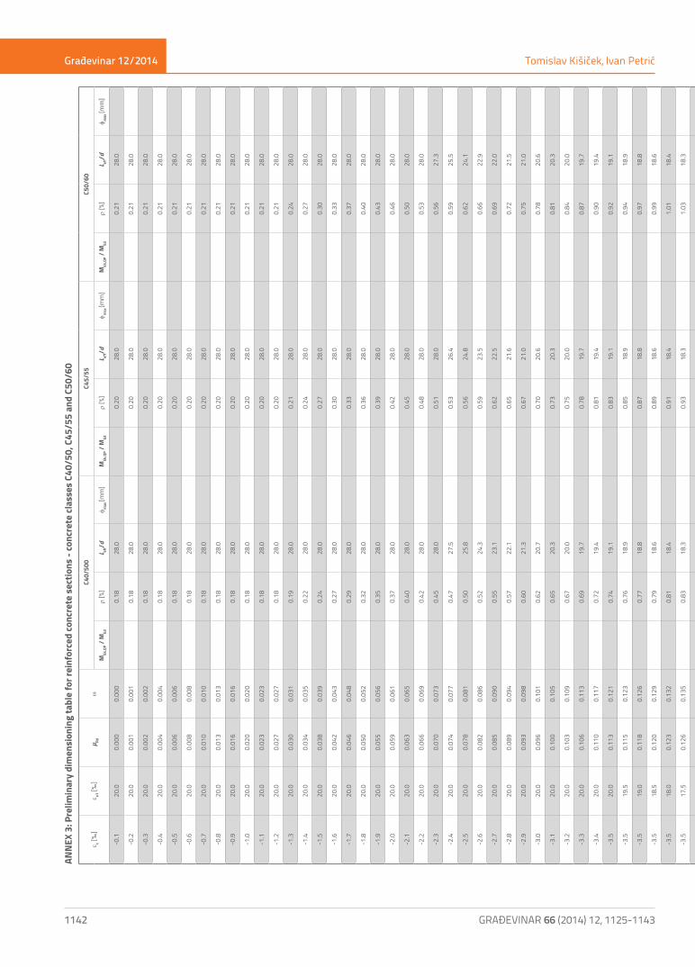
Građevinar 12/2014
1142 GRAĐEVINAR 66 (2014) 12, 1125-1143
e c [‰]
e s1 [‰
]µ Rd
wC4
0/50
0C4
5/55
C50/
60
MEk
,QP /
MEd
r [%
]L ef
f/dφ m
ax [m
m]
MEk
,QP /
MEd
r [%
]L ef
f/dφ m
ax [m
m]
MEk
,QP /
MEd
r [%
]L ef
f/dφ m
ax [m
m]
-0.1
20.0
0.00
00.
000
0.
1828
.0
0.
2028
.0
0.
2128
.0
-0.2
20.0
0.00
10.
001
0.
1828
.0
0.
2028
.0
0.
2128
.0
-0.3
20.0
0.00
20.
002
0.
1828
.0
0.
2028
.0
0.
2128
.0
-0.4
20.0
0.00
40.
004
0.
1828
.0
0.
2028
.0
0.
2128
.0
-0.5
20.0
0.00
60.
006
0.
1828
.0
0.
2028
.0
0.
2128
.0
-0.6
20.0
0.00
80.
008
0.
1828
.0
0.
2028
.0
0.
2128
.0
-0.7
20.0
0.01
00.
010
0.
1828
.0
0.
2028
.0
0.
2128
.0
-0.8
20.0
0.01
30.
013
0.
1828
.0
0.
2028
.0
0.
2128
.0
-0.9
20.0
0.01
60.
016
0.
1828
.0
0.
2028
.0
0.
2128
.0
-1.0
20.0
0.02
00.
020
0.
1828
.0
0.
2028
.0
0.
2128
.0
-1.1
20.0
0.02
30.
023
0.
1828
.0
0.
2028
.0
0.
2128
.0
-1.2
20.0
0.02
70.
027
0.
1828
.0
0.
2028
.0
0.
2128
.0
-1.3
20.0
0.03
00.
031
0.
1928
.0
0.
2128
.0
0.
2428
.0
-1.4
20.0
0.03
40.
035
0.
2228
.0
0.
2428
.0
0.
2728
.0
-1.5
20.0
0.03
80.
039
0.
2428
.0
0.
2728
.0
0.
3028
.0
-1.6
20.0
0.04
20.
043
0.
2728
.0
0.
3028
.0
0.
3328
.0
-1.7
20.0
0.04
60.
048
0.
2928
.0
0.
3328
.0
0.
3728
.0
-1.8
20.0
0.05
00.
052
0.
3228
.0
0.
3628
.0
0.
4028
.0
-1.9
20.0
0.05
50.
056
0.
3528
.0
0.
3928
.0
0.
4328
.0
-2.0
20.0
0.05
90.
061
0.
3728
.0
0.
4228
.0
0.
4628
.0
-2.1
20.0
0.06
30.
065
0.
4028
.0
0.
4528
.0
0.
5028
.0
-2.2
20.0
0.06
60.
069
0.
4228
.0
0.
4828
.0
0.
5328
.0
-2.3
20.0
0.07
00.
073
0.
4528
.0
0.
5128
.0
0.
5627
.3
-2.4
20.0
0.07
40.
077
0.
4727
.5
0.
5326
.4
0.
5925
.5
-2.5
20.0
0.07
80.
081
0.
5025
.8
0.
5624
.8
0.
6224
.1
-2.6
20.0
0.08
20.
086
0.
5224
.3
0.
5923
.5
0.
6622
.9
-2.7
20.0
0.08
50.
090
0.
5523
.1
0.
6222
.5
0.
6922
.0
-2.8
20.0
0.08
90.
094
0.
5722
.1
0.
6521
.6
0.
7221
.5
-2.9
20.0
0.09
30.
098
0.
6021
.3
0.
6721
.0
0.
7521
.0
-3.0
20.0
0.09
60.
101
0.
6220
.7
0.
7020
.6
0.
7820
.6
-3.1
20.0
0.10
00.
105
0.
6520
.3
0.
7320
.3
0.
8120
.3
-3.2
20.0
0.10
30.
109
0.
6720
.0
0.
7520
.0
0.
8420
.0
-3.3
20.0
0.10
60.
113
0.
6919
.7
0.
7819
.7
0.
8719
.7
-3.4
20.0
0.11
00.
117
0.
7219
.4
0.
8119
.4
0.
9019
.4
-3.5
20.0
0.11
30.
121
0.
7419
.1
0.
8319
.1
0.
9219
.1
-3.5
19.5
0.11
50.
123
0.
7618
.9
0.
8518
.9
0.
9418
.9
-3.5
19.0
0.11
80.
126
0.
7718
.8
0.
8718
.8
0.
9718
.8
-3.5
18.5
0.12
00.
129
0.
7918
.6
0.
8918
.6
0.
9918
.6
-3.5
18.0
0.12
30.
132
0.
8118
.4
0.91
18.4
1.
0118
.4
-3.5
17.5
0.12
60.
135
0.
8318
.3
0.93
18.3
1.
0318
.3
-3.5
17.0
0.12
80.
138
0.
8518
.1
0.95
18.1
1.
0618
.1
-3.5
16.5
0.13
10.
142
0.
8717
.9
0.98
17.9
1.
0917
.9
-3.5
16.0
0.13
40.
145
0.
8917
.7
1.00
17.7
1.
1117
.7
-3.5
15.5
0.13
80.
149
0.
9117
.6
1.03
17.6
1.
1417
.6
-3.5
15.0
0.14
10.
153
0.
9417
.4
1.06
17.4
1.
1717
.4
-3.5
14.5
0.14
50.
157
0.
9717
.27
1.
0917
.2
1.21
17.2
-3.5
14.0
0.14
80.
162
0.
9917
.07
1.
1217
.0
1.24
17.0
-3.5
13.5
0.15
20.
167
1.
0216
.97
1.
1516
.9
1.28
16.9
-3.5
13.0
0.15
70.
172
1.
0516
.78
1.
1816
.78
1.
3216
.78
-3.5
12.5
0.16
10.
177
1.
0916
.58
1.
2216
.58
1.
3616
.58
-3.5
12.0
0.16
60.
183
1.
1216
.48
1.
2616
.49
1.
4016
.49
-3.5
11.5
0.17
10.
189
1.
1616
.29
1.
3016
.29
1.
4516
.29
-3.5
11.0
0.17
60.
195
1.
2016
.09
1.
3516
.09
1.
5016
.010
-3.5
10.5
0.18
10.
202
0.74
1.24
15.8
10
1.40
15.8
10
1.55
15.8
10
-3.5
10.0
0.18
70.
210
0.72
1.29
15.7
110.
741.
4515
.711
1.
6115
.711
-3.5
9.5
0.19
40.
218
0.71
1.34
15.5
110.
731.
5015
.511
0.74
1.67
15.5
11
-3.5
9.0
0.20
00.
227
0.69
1.39
15.3
120.
711.
5615
.312
0.72
1.74
15.3
12
-3.5
8.5
0.20
70.
236
0.68
1.45
15.1
130.
691.
6315
.113
0.71
1.81
15.1
13
-3.5
8.0
0.21
50.
246
0.66
1.51
15.0
140.
671.
7015
.014
0.69
1.89
15.0
14
-3.5
7.5
0.22
30.
258
0.64
1.58
14.8
150.
661.
7814
.815
0.67
1.97
14.8
15
-3.5
7.0
0.23
20.
270
0.62
1.66
14.6
160.
641.
8614
.616
0.65
2.07
14.6
16
-3.5
6.5
0.24
20.
283
0.61
1.74
14.5
170.
621.
9614
.517
0.63
2.17
14.5
18
-3.5
6.0
0.25
30.
298
0.59
1.83
14.3
180.
602.
0614
.319
0.61
2.29
14.3
19
-3.5
5.5
0.26
40.
315
0.57
1.93
14.1
200.
582.
1714
.120
0.59
2.41
14.1
21
-3.5
5.0
0.27
60.
333
0.55
2.04
13.9
220.
562.
3013
.922
0.58
2.56
13.9
23
-3.5
4.5
0.29
00.
354
0.54
2.17
13.8
240.
552.
4413
.824
0.56
2.72
13.8
25
-3.5
4.3
0.29
60.
364
0.53
2.23
13.7
250.
542.
5113
.726
0.55
2.79
13.7
26
-3.5
4.0
0.30
40.
378
0.52
2.32
13.6
260.
532.
6113
.627
0.54
2.90
13.6
28
-3.5
3.8
0.31
10.
388
0.51
2.38
13.5
280.
522.
6813
.528
0.53
2.98
13.5
29
-3.5
3.6
0.31
70.
399
0.50
2.45
13.5
290.
512.
7513
.530
0.52
3.06
13.5
30
-3.5
3.4
0.32
40.
411
0.49
2.52
13.4
300.
502.
8313
.431
0.51
3.15
13.4
32
-3.5
3.2
0.33
10.
423
0.49
2.59
13.3
320.
502.
9213
.332
0.50
3.24
13.3
33
-3.5
3.0
0.33
80.
436
0.48
2.67
13.2
330.
493.
0113
.234
0.50
3.34
13.2
35
-3.5
2.8
0.34
60.
450
0.47
2.76
13.2
350.
483.
1013
.236
0.49
3.45
13.2
37
-3.5
2.6
0.35
40.
464
0.47
2.85
13.1
370.
473.
2013
.138
0.48
3.56
13.1
39
-3.5
2.4
0.36
20.
480
0.46
2.95
13.0
390.
473.
3113
.040
0.47
3.68
13.0
41
-3.5
2.2
0.37
00.
497
0.45
3.05
13.0
410.
463.
4313
.042
0.47
3.81
13.0
43
-3.5
2.0
0.37
90.
515
0.44
3.16
12.9
430.
453.
5512
.945
0.46
3.95
12.9
46
-3.5
1.8
0.38
80.
535
0.44
3.28
12.8
460.
443.
6912
.847
0.45
4.10
12.8
49
-3.5
1.6
0.39
70.
556
0.43
3.41
12.8
490.
443.
8312
.850
0.44
4.26
12.8
52
-3.5
1.4
0.40
60.
578
0.42
3.55
12.7
520.
433.
9912
.754
0.44
4.43
12.7
56
-3.5
1.2
0.41
60.
603
0.42
3.70
12.6
560.
424.
1612
.658
0.43
4.62
12.6
60
-3.5
1.0
0.42
60.
630
0.41
3.86
12.6
560.
424.
3412
.660
0.42
4.83
12.6
64
-3.5
0.8
0.43
60.
659
0.40
4.04
12.5
560.
414.
5512
.560
0.42
5.05
12.5
65
Tomislav Kišiček, Ivan PetrićAN
NEX
3: P
relim
inar
y di
men
sion
ing
tabl
e fo
r rei
nfor
ced
conc
rete
sec
tions
- co
ncre
te cl
asse
s C4
0/50
, C45
/55
and
C50/
60

Građevinar 12/2014
1143GRAĐEVINAR 66 (2014) 12, 1125-1143
Preliminary dimensioning of reinforced concrete sections
e c [‰]
e s1 [‰
]µ Rd
wC4
0/50
0C4
5/55
C50/
60
MEk
,QP /
MEd
r [%
]L ef
f/dφ m
ax [m
m]
MEk
,QP /
MEd
r [%
]L ef
f/dφ m
ax [m
m]
MEk
,QP /
MEd
r [%
]L ef
f/dφ m
ax [m
m]
-0.1
20.0
0.00
00.
000
0.
1828
.0
0.
2028
.0
0.
2128
.0
-0.2
20.0
0.00
10.
001
0.
1828
.0
0.
2028
.0
0.
2128
.0
-0.3
20.0
0.00
20.
002
0.
1828
.0
0.
2028
.0
0.
2128
.0
-0.4
20.0
0.00
40.
004
0.
1828
.0
0.
2028
.0
0.
2128
.0
-0.5
20.0
0.00
60.
006
0.
1828
.0
0.
2028
.0
0.
2128
.0
-0.6
20.0
0.00
80.
008
0.
1828
.0
0.
2028
.0
0.
2128
.0
-0.7
20.0
0.01
00.
010
0.
1828
.0
0.
2028
.0
0.
2128
.0
-0.8
20.0
0.01
30.
013
0.
1828
.0
0.
2028
.0
0.
2128
.0
-0.9
20.0
0.01
60.
016
0.
1828
.0
0.
2028
.0
0.
2128
.0
-1.0
20.0
0.02
00.
020
0.
1828
.0
0.
2028
.0
0.
2128
.0
-1.1
20.0
0.02
30.
023
0.
1828
.0
0.
2028
.0
0.
2128
.0
-1.2
20.0
0.02
70.
027
0.
1828
.0
0.
2028
.0
0.
2128
.0
-1.3
20.0
0.03
00.
031
0.
1928
.0
0.
2128
.0
0.
2428
.0
-1.4
20.0
0.03
40.
035
0.
2228
.0
0.
2428
.0
0.
2728
.0
-1.5
20.0
0.03
80.
039
0.
2428
.0
0.
2728
.0
0.
3028
.0
-1.6
20.0
0.04
20.
043
0.
2728
.0
0.
3028
.0
0.
3328
.0
-1.7
20.0
0.04
60.
048
0.
2928
.0
0.
3328
.0
0.
3728
.0
-1.8
20.0
0.05
00.
052
0.
3228
.0
0.
3628
.0
0.
4028
.0
-1.9
20.0
0.05
50.
056
0.
3528
.0
0.
3928
.0
0.
4328
.0
-2.0
20.0
0.05
90.
061
0.
3728
.0
0.
4228
.0
0.
4628
.0
-2.1
20.0
0.06
30.
065
0.
4028
.0
0.
4528
.0
0.
5028
.0
-2.2
20.0
0.06
60.
069
0.
4228
.0
0.
4828
.0
0.
5328
.0
-2.3
20.0
0.07
00.
073
0.
4528
.0
0.
5128
.0
0.
5627
.3
-2.4
20.0
0.07
40.
077
0.
4727
.5
0.
5326
.4
0.
5925
.5
-2.5
20.0
0.07
80.
081
0.
5025
.8
0.
5624
.8
0.
6224
.1
-2.6
20.0
0.08
20.
086
0.
5224
.3
0.
5923
.5
0.
6622
.9
-2.7
20.0
0.08
50.
090
0.
5523
.1
0.
6222
.5
0.
6922
.0
-2.8
20.0
0.08
90.
094
0.
5722
.1
0.
6521
.6
0.
7221
.5
-2.9
20.0
0.09
30.
098
0.
6021
.3
0.
6721
.0
0.
7521
.0
-3.0
20.0
0.09
60.
101
0.
6220
.7
0.
7020
.6
0.
7820
.6
-3.1
20.0
0.10
00.
105
0.
6520
.3
0.
7320
.3
0.
8120
.3
-3.2
20.0
0.10
30.
109
0.
6720
.0
0.
7520
.0
0.
8420
.0
-3.3
20.0
0.10
60.
113
0.
6919
.7
0.
7819
.7
0.
8719
.7
-3.4
20.0
0.11
00.
117
0.
7219
.4
0.
8119
.4
0.
9019
.4
-3.5
20.0
0.11
30.
121
0.
7419
.1
0.
8319
.1
0.
9219
.1
-3.5
19.5
0.11
50.
123
0.
7618
.9
0.
8518
.9
0.
9418
.9
-3.5
19.0
0.11
80.
126
0.
7718
.8
0.
8718
.8
0.
9718
.8
-3.5
18.5
0.12
00.
129
0.
7918
.6
0.
8918
.6
0.
9918
.6
-3.5
18.0
0.12
30.
132
0.
8118
.4
0.91
18.4
1.
0118
.4
-3.5
17.5
0.12
60.
135
0.
8318
.3
0.93
18.3
1.
0318
.3
-3.5
17.0
0.12
80.
138
0.
8518
.1
0.95
18.1
1.
0618
.1
-3.5
16.5
0.13
10.
142
0.
8717
.9
0.98
17.9
1.
0917
.9
-3.5
16.0
0.13
40.
145
0.
8917
.7
1.00
17.7
1.
1117
.7
-3.5
15.5
0.13
80.
149
0.
9117
.6
1.03
17.6
1.
1417
.6
-3.5
15.0
0.14
10.
153
0.
9417
.4
1.06
17.4
1.
1717
.4
-3.5
14.5
0.14
50.
157
0.
9717
.27
1.
0917
.2
1.21
17.2
-3.5
14.0
0.14
80.
162
0.
9917
.07
1.
1217
.0
1.24
17.0
-3.5
13.5
0.15
20.
167
1.
0216
.97
1.
1516
.9
1.28
16.9
-3.5
13.0
0.15
70.
172
1.
0516
.78
1.
1816
.78
1.
3216
.78
-3.5
12.5
0.16
10.
177
1.
0916
.58
1.
2216
.58
1.
3616
.58
-3.5
12.0
0.16
60.
183
1.
1216
.48
1.
2616
.49
1.
4016
.49
-3.5
11.5
0.17
10.
189
1.
1616
.29
1.
3016
.29
1.
4516
.29
-3.5
11.0
0.17
60.
195
1.
2016
.09
1.
3516
.09
1.
5016
.010
-3.5
10.5
0.18
10.
202
0.74
1.24
15.8
10
1.40
15.8
10
1.55
15.8
10
-3.5
10.0
0.18
70.
210
0.72
1.29
15.7
110.
741.
4515
.711
1.
6115
.711
-3.5
9.5
0.19
40.
218
0.71
1.34
15.5
110.
731.
5015
.511
0.74
1.67
15.5
11
-3.5
9.0
0.20
00.
227
0.69
1.39
15.3
120.
711.
5615
.312
0.72
1.74
15.3
12
-3.5
8.5
0.20
70.
236
0.68
1.45
15.1
130.
691.
6315
.113
0.71
1.81
15.1
13
-3.5
8.0
0.21
50.
246
0.66
1.51
15.0
140.
671.
7015
.014
0.69
1.89
15.0
14
-3.5
7.5
0.22
30.
258
0.64
1.58
14.8
150.
661.
7814
.815
0.67
1.97
14.8
15
-3.5
7.0
0.23
20.
270
0.62
1.66
14.6
160.
641.
8614
.616
0.65
2.07
14.6
16
-3.5
6.5
0.24
20.
283
0.61
1.74
14.5
170.
621.
9614
.517
0.63
2.17
14.5
18
-3.5
6.0
0.25
30.
298
0.59
1.83
14.3
180.
602.
0614
.319
0.61
2.29
14.3
19
-3.5
5.5
0.26
40.
315
0.57
1.93
14.1
200.
582.
1714
.120
0.59
2.41
14.1
21
-3.5
5.0
0.27
60.
333
0.55
2.04
13.9
220.
562.
3013
.922
0.58
2.56
13.9
23
-3.5
4.5
0.29
00.
354
0.54
2.17
13.8
240.
552.
4413
.824
0.56
2.72
13.8
25
-3.5
4.3
0.29
60.
364
0.53
2.23
13.7
250.
542.
5113
.726
0.55
2.79
13.7
26
-3.5
4.0
0.30
40.
378
0.52
2.32
13.6
260.
532.
6113
.627
0.54
2.90
13.6
28
-3.5
3.8
0.31
10.
388
0.51
2.38
13.5
280.
522.
6813
.528
0.53
2.98
13.5
29
-3.5
3.6
0.31
70.
399
0.50
2.45
13.5
290.
512.
7513
.530
0.52
3.06
13.5
30
-3.5
3.4
0.32
40.
411
0.49
2.52
13.4
300.
502.
8313
.431
0.51
3.15
13.4
32
-3.5
3.2
0.33
10.
423
0.49
2.59
13.3
320.
502.
9213
.332
0.50
3.24
13.3
33
-3.5
3.0
0.33
80.
436
0.48
2.67
13.2
330.
493.
0113
.234
0.50
3.34
13.2
35
-3.5
2.8
0.34
60.
450
0.47
2.76
13.2
350.
483.
1013
.236
0.49
3.45
13.2
37
-3.5
2.6
0.35
40.
464
0.47
2.85
13.1
370.
473.
2013
.138
0.48
3.56
13.1
39
-3.5
2.4
0.36
20.
480
0.46
2.95
13.0
390.
473.
3113
.040
0.47
3.68
13.0
41
-3.5
2.2
0.37
00.
497
0.45
3.05
13.0
410.
463.
4313
.042
0.47
3.81
13.0
43
-3.5
2.0
0.37
90.
515
0.44
3.16
12.9
430.
453.
5512
.945
0.46
3.95
12.9
46
-3.5
1.8
0.38
80.
535
0.44
3.28
12.8
460.
443.
6912
.847
0.45
4.10
12.8
49
-3.5
1.6
0.39
70.
556
0.43
3.41
12.8
490.
443.
8312
.850
0.44
4.26
12.8
52
-3.5
1.4
0.40
60.
578
0.42
3.55
12.7
520.
433.
9912
.754
0.44
4.43
12.7
56
-3.5
1.2
0.41
60.
603
0.42
3.70
12.6
560.
424.
1612
.658
0.43
4.62
12.6
60
-3.5
1.0
0.42
60.
630
0.41
3.86
12.6
560.
424.
3412
.660
0.42
4.83
12.6
64
-3.5
0.8
0.43
60.
659
0.40
4.04
12.5
560.
414.
5512
.560
0.42
5.05
12.5
65