preliminary definition of plants configurations and...
TRANSCRIPT

Preliminary definition of plants configurations and specifications of membrane operating conditions Grant Agreement Number: 241309 Project Acronym: DEMOYS Project Title: Dense Membranes for Efficient Oxygen
and Hydrogen Separation Funding Scheme: Collaborative Project Deliverable n. 4.1 Partner responsible: Foster Wheeler Italiana S.r.l. Authors: Luca Mancuso (FWI) Federico Fazi (FWI) Paolo Chiesa (Polimi) Matteo C. Romano (Polimi) Vincenzo Spallina (Polimi) Janusz Jewulski (IEn) Marcin Blesznowski (IEn)
DELIVERABLE 4.1
Revision no.: Date:
0 31 October 2010 Sheet: 2 of 89
INDEX 1. Introduction ........................................................................................................................ 8
1.1. Background ................................................................................................................ 8 1.2. Objectives and structure of the document .................................................................. 8
2. Benchmark coal and natural gas power plants ................................................................. 10 2.1. Plant description ....................................................................................................... 11
2.1.1. Steam Methane Reforming (SMR) or Auto-thermal Reforming (ATR) for hydrogen production (no CO2 capture) ............................................................................ 11
2.1.2. Natural Gas Combined Cycle (NGCC) (no CO2 capture) ................................ 12
2.1.3. Natural gas combined cycle (NGCC) with post-combustion CO2 capture ...... 13 2.1.4. Auto-Thermal Reforming (ATR) plant with pre-combustion CO2 capture ..... 15 2.1.5. Steam Methane Reforming (SMR) plant with pre (or post) combustion CO2 capture 17 2.1.6. Integrated Gasification Combined Cycle (IGCC) (no CO2 capture) ................ 18
2.1.7. Integrated Gasification Combined Cycle (IGCC) with pre-combustion CO2 capture 20 2.1.8. Ultra Super Critical Pulverized Coal (USC-PC) boiler plant (no CO2 capture) 21
2.1.9. USC-PC boiler plant with post-combustion capture ........................................ 22
2.1.10. Oxy-combustion USC-PC boiler and cryogenic purification .......................... 23
2.2. Performance and cost data of benchmark technologies ........................................... 27
3. General feature of Ion Transport Membranes .................................................................. 30 3.1. Fundamentals about mixed conducting membranes ................................................ 30
3.2. Fundamentals about membrane reactors. ................................................................. 32
3.3. Integration of oxygen and hydrogen separation membrane in power/H2 plants ...... 34 4. Mapping of membrane integrated coal based power plants from literature ..................... 35
4.1. Integrated Gasification Combined Cycle (IGCC) .................................................... 35
4.2. Oxy-fired plants ........................................................................................................ 39 4.3. Summary findings from literature mapping ............................................................. 44
4.4. References ................................................................................................................ 48 5. Mapping of membrane integrated natural gas-based power plants from literature .......... 50
5.1. Oxy-fuel NGCC integrated with oxygen separation membranes ............................. 50
5.2. SMR integrated with hydrogen separation membranes ........................................... 55
5.2.1. Configuration 1: Hydrogen Separation Membrane in a Fired Tubular Reactor 55
5.2.2. Configuration 2: Multi-stage hydrogen separation membrane reformer ......... 58
5.2.3. Configuration 3: SMR with hydrogen separation membrane .......................... 60
5.2.4. Configuration 4: Membrane-reformer with permeate side combustion ........... 63
5.3. ATR integrated with oxygen separation membranes ............................................... 68
5.3.1. OTM integrated in conventional ATR ............................................................. 68
5.3.2. OTM integrated in Catalytic Partial Oxidation ................................................ 69
5.4. ATR integrated with oxygen and hydrogen separation membranes ........................ 71
5.4.1. Single component oxygen/hydrogen separation membrane-reformer ............. 71
5.4.2. Two components oxygen/hydrogen separation membrane-reformer ............... 72 5.4.3. Two components oxygen/hydrogen separation membrane-CPO reactor ......... 72

DELIVERABLE 4.1
Revision no.: Date:
0 31 October 2010 Sheet: 3 of 89
5.5. References ................................................................................................................ 75
6. Selected plant configurations ........................................................................................... 77 6.1. Coal-based plants ..................................................................................................... 77
6.1.1. Integrated Gasification Combined Cycle (IGCC) ............................................ 77
6.1.2. Oxy-fired plants ................................................................................................ 79 6.2. Natural gas-based plants ........................................................................................... 81
6.2.1. Oxyfuel NGCC plants ...................................................................................... 81 6.2.2. Steam methane reforming plants (SMR) .......................................................... 82
6.2.3. Auto-thermal reforming plants (ATR) ............................................................. 84
7. Membranes operating conditions ..................................................................................... 87 7.1. Oxygen membranes .................................................................................................. 88 7.2. Hydrogen membranes .............................................................................................. 89
DELIVERABLE 4.1
Revision no.: Date:
0 31 October 2010 Sheet: 4 of 89
LIST OF FIGURES Figure 2.1 – De-carbonization schemes in industrial plants .................................................... 10 Figure 2.2 – SMR process scheme for hydrogen production (no CO2 capture) ....................... 12
Figure 2.3 – NGCC process scheme (no CO2 capture) ............................................................ 13 Figure 2.4 – NGCC process scheme with post-combustion CO2 capture ................................ 14
Figure 2.5 – ATR with pre-combustion CO2 capture (power and/or H2 production) .............. 16
Figure 2.6 – SMR with pre-combustion CO2 capture (power and/or H2 production) .............. 17
Figure 2.7 – IGCC process scheme (no CO2 capture) .............................................................. 19 Figure 2.8 – IGCC process scheme with pre-combustion CO2 capture ................................... 20
Figure 2.9 – USC-PC process scheme (no CO2 capture) ......................................................... 21 Figure 2.10 – USCPC process scheme with post-combustion CO2 capture ............................ 23
Figure 2.11 – Oxy combusted USC-PC process scheme with cryogenic CO2 purification ..... 24 Figure 2.12 – Auto-refrigerated process scheme for CO2 cryogenic purification ................... 26
Figure 3.1 – Oxygen transport membrane concept [1] ............................................................. 31 Figure 3.2 – Generic mixed conducting membrane simplified scheme ................................... 32
Figure 3.3 – Hydrogen Separation Membrane Reactor in a shell-and-tube arrangement. ....... 33
Figure 4.1 – Integration of OTM with boost compressor/recuperator which minimizes GT design impact [Stein, 2007] .............................................................................................. 36
Figure 4.2 – Net efficiency of IGCC process vs. pressure of the sweep stream [Sander, 2006]. .......................................................................................................................................... 38
Figure 4.3 –IGCC with Steam-purged OTM [Prasad, 2002] ................................................... 38
Figure 4.4 – Externally Fired Combined Cycles (EFCC) [Romano, 2005] ............................. 41
Figure 4.5 – Fluidized bed combustion USC (basic scheme) [Romano, 2005]. ...................... 42
Figure 5.1 – Schematic of the plant proposed by Colombo and Bolland [2], where heat transfer, oxygen separation and combustion in MCM reactor are carried out in separate components. ...................................................................................................................... 51
Figure 5.2 – Schematic of the AZEP cycle [1]. ....................................................................... 52 Figure 5.3 – MCM reactor where heat transfer, oxygen separation and combustion occur in
one single component [4] ................................................................................................. 52 Figure 5.4 – Integration of Hydrogen Separation Membrane in a Fired Tubular Reactor [12].
.......................................................................................................................................... 55
Figure 5.5 – Schematic flow diagram of the Hydrogen Separation Membrane Reformer system [13]. ...................................................................................................................... 56
Figure 5.6 – Variations of off gas composition and conversion as a function of natural gas feed rate [13]. ................................................................................................................... 57
Figure 5.7 – Plant based on a multi-stage hydrogen separation membrane reformer proposed in [5]. ................................................................................................................................ 58
Figure 5.8 – Principle and typical configuration of the methane steam reformer with hydrogen separation membrane investigated in [7]. ........................................................................ 60
Figure 5.9 – Plant layouts considered in [7]............................................................................. 62 Figure 5.10 – Process flow diagram of the power plant proposed in [8]. ................................ 64
Figure 5.11 – Schematic of the membrane reactor design proposed in [8]. ............................. 66
Figure 5.12 – Integration of Oxygen Transport Membrane with conventional Auto-Thermal Reformer. .......................................................................................................................... 68
Figure 5.13 – Oxygen Separation Membrane (CPO) Reactor. ................................................ 69

DELIVERABLE 4.1
Revision no.: Date:
0 31 October 2010 Sheet: 5 of 89
Figure 5.14 – Integrated O2/H2 separation membrane in a single unit proposed in [14]. ........ 71 Figure 5.15 – OTM with Hydrogen Separation Membrane Autothermal Reformer. .............. 72
Figure 5.16 – Oxygen Separation Membrane CPO Reactor with Hydrogen Separation Membrane Reformer. ....................................................................................................... 73
Figure 5.17 – Process flow diagram of the power plant proposed in [9]. ................................ 74
Figure 6.1 – Coal Integrated Gasification Combined Cycle integrated with OTM. ................ 78
Figure 6.2 – Coal fluidized bed oxy-combustion boiler plant integrated with OTM. .............. 80
Figure 6.3 – Steam Methane Reforming based on H2 separation membrane-reactor. ............ 83
Figure 6.4 – Natural gas Auto-thermal Reforming integrated with OTM. ............................. 84
Figure 6.5 – Natural gas Auto-thermal Reforming with H2 Separation Membrane Reformer and integrated with OTM. ................................................................................................ 85

DELIVERABLE 4.1
Revision no.: Date:
0 31 October 2010 Sheet: 6 of 89
LIST OF TABLES Table 2.1 – Expected Performance and cost data of benchmark technologies for NG-based
plants. ............................................................................................................................... 28
Table 2.2 – Expected Performance and cost data of benchmark technologies for coal-based plants ................................................................................................................................ 29
Table 3.1 – Potential integration of oxygen and hydrogen separation membrane in power/H2 plants with CCS. ............................................................................................................... 34
Table 4.1 – Air Products system design specifications with alternative ASU technologies [Stein 2007] ...................................................................................................................... 35
Table 4.2 – Breakdown of total fixed capital for large and small-scale OTM systems (the HRSG is not used in the latter system) [Exter, 2009] ...................................................... 37
Table 4.3 – IGCC systems with alternative ASU technologies (Praxair) [Prasad, 2002] ........ 39
Table 4.4 – Comparison between Cryogenic and Membrane Technologies [Selzer] .............. 40
Table 4.5 – Main, characteristic values which concern EFCC and FBC-USC ........................ 40
Table 4.6 – Main parameters that affect OTM-based plant design .......................................... 41
Table 4.7 – Comparison between chosen technologies [Romano, 2005] ................................ 43
Table 4.8 – Cost saving of OTM technology with respect to Cryogenic ASU [Armstrong, 2004] ................................................................................................................................. 44
Table 4.9 – Main technological details concerning application of membranes in coal power generation plants. ............................................................................................................. 45
Table 5.1 – Performance calculated in [5] for a plant based on Hydrogen Mixed Conducting ceramic Membranes. ........................................................................................................ 60
Table 5.2 – Conditions of the streams at inlet and outlet of the membrane separation reformer presented in [3]. Mass flow rates are referred to 1 kg/s CH4 input. Case of Pd-alloy membrane with 600°C at the reformer input. The resulting HSF is 90.7%. .................... 62
Table 5.3 – Conditions of the streams at inlet and outlet of the membrane separation reformer presented in [3]. Mass flow rates are referred to 1 kg/s CH4 input. Case of Pd-alloy membrane with 650°C at the reformer input. The resulting HSF is 94.4%. .................... 62
Table 5.4 – Conditions of the streams at inlet and outlet of the membrane separation reformer presented in [3]. Mass flow rates are referred to 1 kg/s CH4 input. Case of microporous membrane with 600°C at the reformer input. The resulting HSF is 86.3%. .................... 63
Table 5.5 – Conditions of the streams at inlet and outlet of the membrane separation reformer presented in [3]. Mass flow rates are referred to 1 kg/s CH4 input. Case of microporous membrane with 650°C at the reformer input. The resulting HSF is 92.3%. .................... 63
Table 5.6 – Performance of the different plant configurations presented in [7]. ..................... 63
Table 5.7 – Summary of the results obtained in [8]. ................................................................ 67 Table 5.8 – Properties of the streams for case B2 of the plant considered in [8]. .................... 67
Table 7.1 – Summary of expected operating conditions of oxygen separation membranes. ... 88
Table 7.2 – Summary of expected operating conditions of hydrogen separation membranes. 89

DELIVERABLE 4.1
Revision no.: Date:
0 31 October 2010 Sheet: 7 of 89
ABBREVIATIONS
AGR Acid Gas Removal ASU Air Separation Unit ATR Auto Thermal Reformer AZEP Advanced Zero Emission Power Plant BHX Bleed Gas Exchanger BFW Boiler Feed Water BL Battery Limits BOP Balance Of Plant CC Combined Cycle CFB Circulating Fulidized Bed COE Cost Of Electricity CPO Catalytic Partial Oxydation EFCC External Fired Combined Cycle FBC Fluidized Bed Combustion FGD Flue Gas Desulphurization FGT Flue Gas Treatment FTR Fired Tubular Reactor GT Gas Turbine HHV High Heating Value HP High Pressure HRSG Heat Recovery Steam Generator HSF Hydrogen Separation Factor HTM Hydrogen Transport Membrane IP Intermediate Pressure ITM Ion Transport Membrane LHV Low Heating Value LP Low Pressure MCM Mixed Conducting Membrane MDEA Methyl Di-Ethyl Amine MEA Mono-Ethanol-Amine MP Medium Pressure MWe Mega Watt electrical MWth Mega Watt thermal NG Natural Gas OMCM Oxygen Mixed Conducting Membrane OTM Oxygen Transport Membrane PC Pulverised Coal PSA Pressure Swing Adsorbtion RH Re-Heated SC Steam Cycle SCR Selective Catalytic Reduction SH Superheated SMR Steam Methane Reforming ST Steam Turbine TIC Total Investment Cost TIT Turbine Inlet Temperature USC Ultra Super Critical VLP Very Low Pressure WGS Water Gas Shift

DELIVERABLE 4.1
Revision no.: Date:
0 31 October 2010 Sheet: 8 of 89
1. Introduction
1.1. Background In the scientific community it is generally recognized that, by year 2030, the world energy demand will increase by 50%, while fossil fuels, mainly coal and natural gas, will continue to supply most of the energy demands. This reality will continue for many years, until renewable will become, hopefully, the main resource of energy. The use of fossil fuels is necessarily correlated to the production of carbon dioxide (CO2) that contributes to global warming. As a matter of fact, Carbon Capture and Storage (CCS) represents an effective response to cut CO2 emissions in the next few years. In this scenario, membranes for oxygen and hydrogen separation may also play a key role in the development of CO2 emission-free coal and natural gas power plants. In fact, these membranes can be integrated in conventional industrial applications, leading to novel configurations that have potentialities for higher performances and lower investment costs. Therefore, the main objectives of the DEMOYS project is the development of mixed conducting membranes through a new deposition technique and a technical and economic assessment of their integration in conventional coal and natural gas fired power plants.
1.2. Objectives and structure of the document As part of the DEMOYS project, this document belongs to the Work Package number 4 (WP4), which has the main objective of assessing the membrane integration in power generation plants. At this stage of the project, when membranes have not been fully developed and modelling of power plants has not been made yet, the main objectives of this document are the following: • Show performances and costs of reference commercial technologies (benchmark
technologies) for power and hydrogen production from coal and natural gas, with and without capture of the carbon dioxide.
• Present plant configurations proposed in the scientific literature and research projects, which could be suitable for integration of the membrane technology in power and hydrogen generation plants.
• Make a preliminary selection of industrial process schemes that can be of potential interest for future applications of hydrogen and oxygen separation membranes.
• Specify membrane operating conditions for the preliminary selected plant configurations.

DELIVERABLE 4.1
Revision no.: Date:
0 31 October 2010 Sheet: 9 of 89
The outcomes of this document will then be used for the further development of the WP4, while providing inputs to the membrane development (WP2) and to the preliminary evaluation of CO2 capture cost in the selected plant configurations (WP6). The structure of this document is as follows: • Section 2 shows performances and costs of benchmark technologies with and
without CCS. • Section 3 presents the main features of the oxygen and hydrogen transport
membranes and their potential use in power/H2 plants. • Section 4 makes a mapping of plant configurations proposed in the scientific
literature and research projects for coal based power plants. • Section 5 makes a mapping of plant configurations proposed in the scientific
literature and research projects for natural gas based power plants. • Section 6 makes a preliminary selection of industrial process schemes, which
can be of potential interest for future membrane applications. • Section 7 specifies the expected operating conditions of the membranes for the
selected process schemes.
DELIVERABLE 4.1
Revision no.: Date:
0 31 October 2010 Sheet: 10 of 89
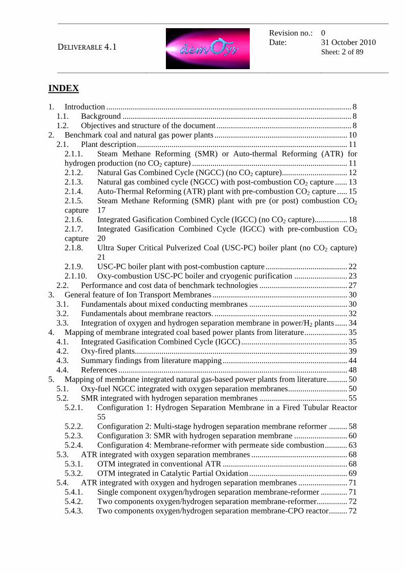
2. Benchmark coal and natural gas power plants As stated in the previous section, the main objectives of the DEMOYS project is the development of mixed conducting membranes through a new deposition technique and a technical and economic assessment of their integration in coal and natural gas fired power plants, with low carbon dioxide emissions. This will lead to novel plant configurations, whose performances and costs will be compared to those of benchmark technologies, already commercially available or at least in an advanced development status, which make the capture of the produced carbon dioxide. Carbon capture (or de-carbonisation) processes in a coal or natural gas power plant fall in one of the following three main categories (Figure 2.1): 1) Pre-combustion: CO2 separation from synthesis gas, downstream a water gas
shift reactor that converts CO and water to CO2 and hydrogen. This solution implies the re-allocation of the heating value contained in the original feedstock in a "de-carbonized" fuel (hydrogen) that feeds the power cycle. Hydrogen can then be used as a substitute of the original fossil fuel, with minor modifications of the reference commercial power cycles, or exported from the plant (e.g. as "premium fuel" in the transportation sector).
2) Oxy-combustion: CO2 concentration in the exhaust gases. In this case the energy conversion process is modified (typically by using oxygen combustion) and suitable techniques are applied so that CO2 can be removed at a convenient stage of the process with a high purity degree.
3) Post-combustion: CO2 separation from flue gases. It is put into practice through an end-of-pipe separation process, placed upstream of the stack, with no or minor modifications of the conventional plants.
Figure 2.1 – De-carbonization schemes in industrial plants

DELIVERABLE 4.1
Revision no.: Date:
0 31 October 2010 Sheet: 11 of 89
Other processes for carbon capture such as chemical looping or oxy-combustion applied to gas turbines (e.g. Graz cycle, semi-closed oxygen combustion combined cycle, etc.), even if they are promising novel technologies, are not investigated in this document because they are still far from commercialisation. The following section 2.1 makes the plant descriptions of the coal and natural gas-based benchmark technologies, with and without capture of the CO2, while section 2.2 shows their main performances and cost data.
2.1. Plant description
2.1.1. Steam Methane Reforming (SMR) or Auto-thermal Reforming (ATR) for hydrogen production (no CO2 capture) The Steam Methane Reforming (SMR) process is generally used for the production of hydrogen, converting natural gas into syngas using Medium Pressure (MP) steam as shown in Figure 2.2. After a desulphurization pre-stage (sulphur in minimal parts - i.e. around or less than 1 ppm - is a poison for catalyzers used in the process), Natural Gas feed is initially mixed with superheated MP steam, before being fed to the pre-reformer, where heavy hydrocarbons are fully reformed, while methane is partially reformed. Downstream, in the SMR process, methane is completely steam reformed. The reformer effluent contains H2, CO, CO2 and some CH4, H2O and N2, if present in the natural gas. The process steam added to the feed is in excess to the stoichiometric quantity, to prevent carbon formation on the catalyst. The produced syngas leaves the Steam Reformer and passes through a waste heat boiler where it is further cooled to recover heat and to generate MP superheated steam. The Steam Reformer effluent flows to the shift reactor where excess steam converts most of the CO to CO2 and H2 over a catalyst bed. The shifted raw gas is cooled in a heat exchangers train in which the waste heat is recovered to generate steam, to pre-heat various process streams and water. The purification of hydrogen into the H2- rich gas is traditionally made by means of PSA (Pressure Swing Adsorbtion) in order to recover almost pure hydrogen by a cyclic adsorption process. The low pressure off-gas stream from the PSA, containing the removed impurities and some residual hydrogen, is returned to the Steam Reformer Furnace to supply most of its fuel requirement. For Auto-thermal Reforming plant (ATR), the main difference with respect to the SMR configuration is that the endothermic reforming reaction heat is supplied by

DELIVERABLE 4.1
Revision no.: Date:
0 31 October 2010 Sheet: 12 of 89
injection of oxygen inside the reactor catalyst bed, instead of external burning. The rest of the plant is similar to the SMR process.
Syngas Cooling
Natural Gas
Shift Reactor
Raw Syngas
SteamReformer
MP Steam
PSA
Hydrogen
PSAoff-gas
Pre-Reformer
Figure 2.2 – SMR process scheme for hydrogen production (no CO2 capture)
2.1.2. Natural Gas Combined Cycle (NGCC) (no CO2 capture)
The Natural Gas Combined Cycle is mainly composed of one gas turbine, one Heat Recovery Steam Generator (HRSG) generating steam at three levels of pressure, and one steam turbine, water-cooled and condensing type (Figure 2.3). Natural gas from the distribution grid is eventually compressed at the adequate pressure to feed the Gas Turbine. Natural gas is then pre-heated and combusted in the Gas Turbine to produce electric power. The exhaust gases from the Gas Turbine are conveyed to the Heat Recovery Steam Generator, located downstream of the machine and connected by means of an exhaust duct. The steam generated in the HRSG is fed to the steam turbine to increase the power production of the plant. The condensate stream, extracted from the steam condenser by means of condensate pumps, is sent to the HRSG deaerator in the combined cycle. Degassed Boiler Feed Water (BFW) for HP and MP steam generation is directly taken from the deaerator and delivered to the relevant users by means of dedicated pumps.

DELIVERABLE 4.1
Revision no.: Date:
0 31 October 2010 Sheet: 13 of 89
The generated HP steam is superheated in the HP superheater coils and then sent to the HP module of the steam turbine. HP module exhaust are mixed with superheated MP steam from the MP steam generator and then reheated before admission in the MP steam turbine module. The superheated LP steam from the LP superheater coils is mixed with the exhaust of the MP module and then enters the LP module of the steam turbine. The wet steam at the outlet of the LP module of the steam turbine is routed to the water-cooled condenser and then condensed against the plant cooling water. The condensate from the condenser is finally sent back to the HRSG to re-start the water/steam generation process.
HRSG
Gas TurbineSteam Cycle
Stack
Natural Gas
Air
Figure 2.3 – NGCC process scheme (no CO2 capture)
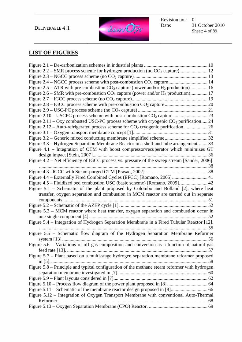
2.1.3. Natural gas combined cycle (NGCC) with post-combustion CO2 capture
With respect to the NGCC without carbon capture (described in the previous section), the flue gases from the HRSG, instead of being discharged to the atmosphere, are diverted to a post-combustion carbon capture unit (Acid Gas Removal or AGR), which separates most of the CO2 (Figure 2.4). Absorption in chemical solvents, mainly amines, is a commercially available technology, though it has not been proven at large scale power plants yet. However, it has been already used in natural gas sweetening and hydrogen production processes. The reaction between CO2 and amines currently offers the most cost-effective solution for the production of a high-purity CO2 stream. The flue gases from the HRSG are cooled in a dedicated flue gas direct contact cooler, before entering the absorption column. Downstream the direct contact cooler, the flue gas is fed to the absorption tower by means of a flue gas blower that overcomes the pressure drop of the system. A lean amine solution, typically Mono-
DELIVERABLE 4.1
Revision no.: Date:
0 31 October 2010 Sheet: 14 of 89
Ethanol-Amine (MEA), counter-currently interacts with the flue gases to absorb the CO2. The clean flue gases then flow to the stack, optionally after pre-heating in a gas-gas heating exchanger. Some of the heat reaction of the solvent with the CO2 is removed by the pump around coolers, located at different sections of the absorption column. Before leaving the column, the sweet gas is scrubbed with make-up water to remove the entrained solvent and avoid any dispersion to the atmosphere. From the bottom of the absorption column, the rich solvent is heated in a regenerative cross exchanger against the hot stripper bottom and sent to the regeneration column, which is composed of a stripping section. LP steam necessary for solvent regeneration comes from the combined cycle, while saturated condensate is pumped back to the deaerator. The vapour at the top of the column passes through the overhead stripper condenser, where it is cooled versus cold condensate from the steam turbine condenser. At the overhead stripper condenser outlet, water vapor is condensed and separated generating the rich CO2 stream, which flows to the CO2 compression unit, while condensed water is partially returned to the column as reflux. The lean solvent at the bottom of the stripping column is pumped back to the absorption, after final cooling against cooling water.
HRSG
Gas Turbine Steam Cycle
CO2
Natural Gas
Air
Stack
StripperAbsorber
CO2 Compression
Combined Cycle
AGR
Figure 2.4 – NGCC process scheme with post-combustion CO2 capture

DELIVERABLE 4.1
Revision no.: Date:
0 31 October 2010 Sheet: 15 of 89
2.1.4. Auto-Thermal Reforming (ATR) plant with pre-combustion CO2 capture
The ATR process converts natural gas into syngas, using MP steam and process air (or oxygen), as shown in Figure 2.5. Natural Gas feed is initially mixed with superheated MP steam, before being fed to the pre-reformer, where heavy hydrocarbons are fully reformed, while methane is partially reformed. The pre-reformed gas is fed to the ATR reactor, which uses air (or oxygen) as oxidant. The syngas leaves the ATR at very high temperature and is cooled, generating HP steam, before entering the shift reactor that converts the CO in the gas leaving the ATR into CO2 according to the following exothermic “water-gas shift” reaction:
CO + H2O → CO2 + H2 Upon leaving the shift reactors, the syngas consisting mainly of H2, steam, N2 and CO2 is cooled before entering the Acid Gas Removal Unit for removal of carbon dioxide. The AGR captures the carbon dioxide from the hydrogen-rich fuel (or shifted gas), producing a de-carbonized fuel, suitable for power generation in the combined cycle (Figure 2.5). The AGR may use either a chemical solvent (e.g. MDEA) or a physical solvent (e.g. Selexol) and the captured CO2 is delivered to the CO2 compressor. In case of power production, the combined cycle is mainly composed of one gas turbine, one Heat Recovery Steam Generator (HRSG) generating steam at three levels of pressure, and one steam turbine, water-cooled condensing type. The combined cycle is similar to that of a conventional natural gas fired plant, though there is a strong thermal integration between the different process units, in order to increase the net electrical efficiency of the plant. In case of hydrogen production, oxygen is generally used as oxidant in the reformer, so the gas leaving the AGR has already high-hydrogen content that can be further purified through a conventional Pressure Swing Adsorption (PSA) process.

DELIVERABLE 4.1
Revision no.: Date:
0 31 October 2010 Sheet: 16 of 89
Syngas Cooling
Combined Cycle
HRSG
Gas Turbine Steam CycleAir
StackNatural Gas
Air (or Oxygen)
Shift Reactor
Decarbonized Fuel
Raw Syngas
Pre-Reformer
Auto-ThermalReformer
MP Steam
StripperAbsorber
AGRCO2
CO2 Compression
PSA
Hydrogen
PSAoff-gas
Figure 2.5 – ATR with pre-combustion CO2 capture (power and/or H2 production)
DELIVERABLE 4.1
Revision no.: Date:
0 31 October 2010 Sheet: 17 of 89
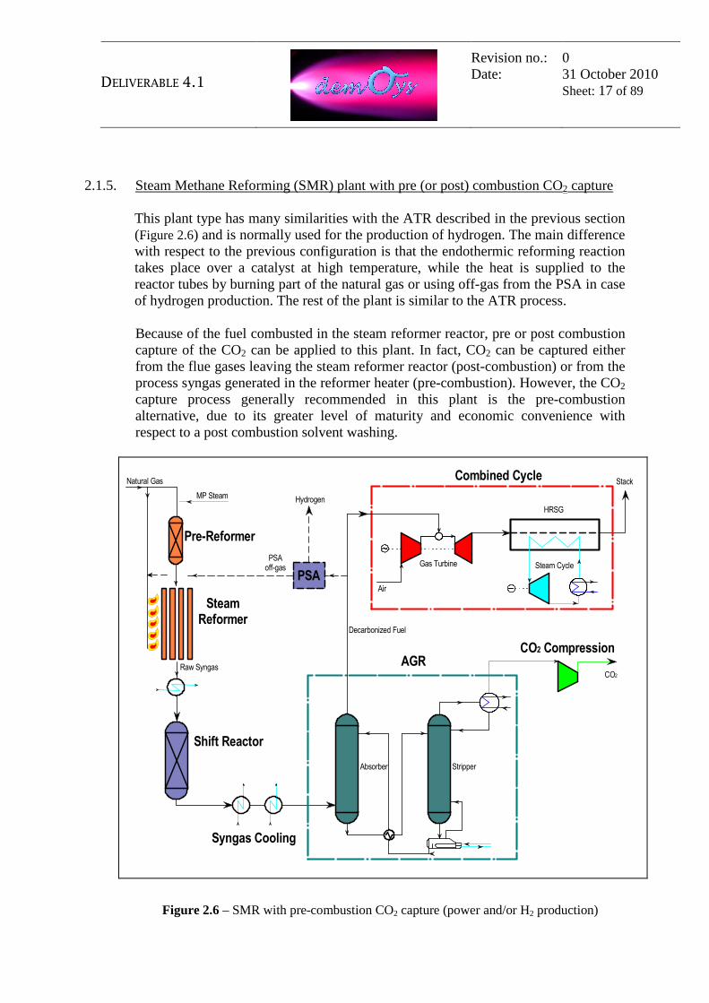
2.1.5. Steam Methane Reforming (SMR) plant with pre (or post) combustion CO2 capture
This plant type has many similarities with the ATR described in the previous section (Figure 2.6) and is normally used for the production of hydrogen. The main difference with respect to the previous configuration is that the endothermic reforming reaction takes place over a catalyst at high temperature, while the heat is supplied to the reactor tubes by burning part of the natural gas or using off-gas from the PSA in case of hydrogen production. The rest of the plant is similar to the ATR process. Because of the fuel combusted in the steam reformer reactor, pre or post combustion capture of the CO2 can be applied to this plant. In fact, CO2 can be captured either from the flue gases leaving the steam reformer reactor (post-combustion) or from the process syngas generated in the reformer heater (pre-combustion). However, the CO2 capture process generally recommended in this plant is the pre-combustion alternative, due to its greater level of maturity and economic convenience with respect to a post combustion solvent washing.
Syngas Cooling
Combined Cycle
HRSG
Gas Turbine Steam Cycle
Air
StackNatural Gas
Shift Reactor
Decarbonized Fuel
Raw Syngas
SteamReformer
MP Steam
StripperAbsorber
AGRCO2
CO2 Compression
PSA
Hydrogen
PSAoff-gas
Pre-Reformer
Figure 2.6 – SMR with pre-combustion CO2 capture (power and/or H2 production)

DELIVERABLE 4.1
Revision no.: Date:
0 31 October 2010 Sheet: 18 of 89
2.1.6. Integrated Gasification Combined Cycle (IGCC) (no CO2 capture) The IGCC plant (Figure 2.7) is a power production facility that converts coal to electric energy with a minimum impact to the environment. The key process step of the IGCC plant is coal gasification. Gasification is the partial oxidation of coal, or any other heavy feedstock, to a gas, often identified as syngas, in which the major components are hydrogen and carbon monoxide. The fuel also contains other elements such as nitrogen (N2) and carbon dioxide (CO2) and small quantities of H2S (hydrogen sulfide), chlorine, NH3, HCN that are removed from the syngas in the treatment section before combustion in the gas turbine. The oxygen required by the gasifier comes from the Air Separation Unit (ASU), which performs cryogenic separation of ambient air into high purity oxygen and nitrogen streams. Air is compressed and cooled to low temperature such that oxygen and nitrogen, which have different boiling points (respectively −183°C vs. −195.8), can then easily be separated from each other by fractional distillation. The nitrogen is mainly used to dilute the syngas before combustion in the gas turbine. The syngas generated by the gasification is cleaned and then used in a combined cycle. Therefore, the gasification acts as a bridge between a low quality fossil fuel, coal, and the gas turbine with the target of high-energy efficiency and minimum emissions to the environment. The IGCC Complex is a combination of several process units. The main process blocks of the plant are the following: • Coal milling and gasifier feed preparation; • Air Separation Unit; • Gasification Island; • Syngas treatment and conditioning; • Acid Gas Removal, making a solvent washing of the syngas mainly to remove
the H2S originated in the gasification process; • Combined Cycle power generation. These basic blocks are supported by other ancillary units, such as Sulphur recovery, Tail gas treatment, and a number of utility and offsite units, such as cooling water, flare, plant/instrument air, machinery cooling water, demineralised water, auxiliary fuels, etc. Each process unit of the plant may be a single train for the total capacity or split in two, three or more parallel trains, depending on the maximum capacity of the equipment involved or on the necessity to assure, through the use of multiple parallel trains, a superior degree of reliability.

DELIVERABLE 4.1
Revision no.: Date:
0 31 October 2010 Sheet: 19 of 89
Acid Gas
StripperAbsorber
Gasification Island
Combined Cycle
HRSG
Gas Turbine Steam CycleCoal
Air
StackASU(cryogenic separation)
AGR
Oxygen
Air
Sweet Syngas
Raw Syngas
Syngas Cooling
Air
Nitrogen
Figure 2.7 – IGCC process scheme (no CO2 capture)
DELIVERABLE 4.1
Revision no.: Date:
0 31 October 2010 Sheet: 20 of 89
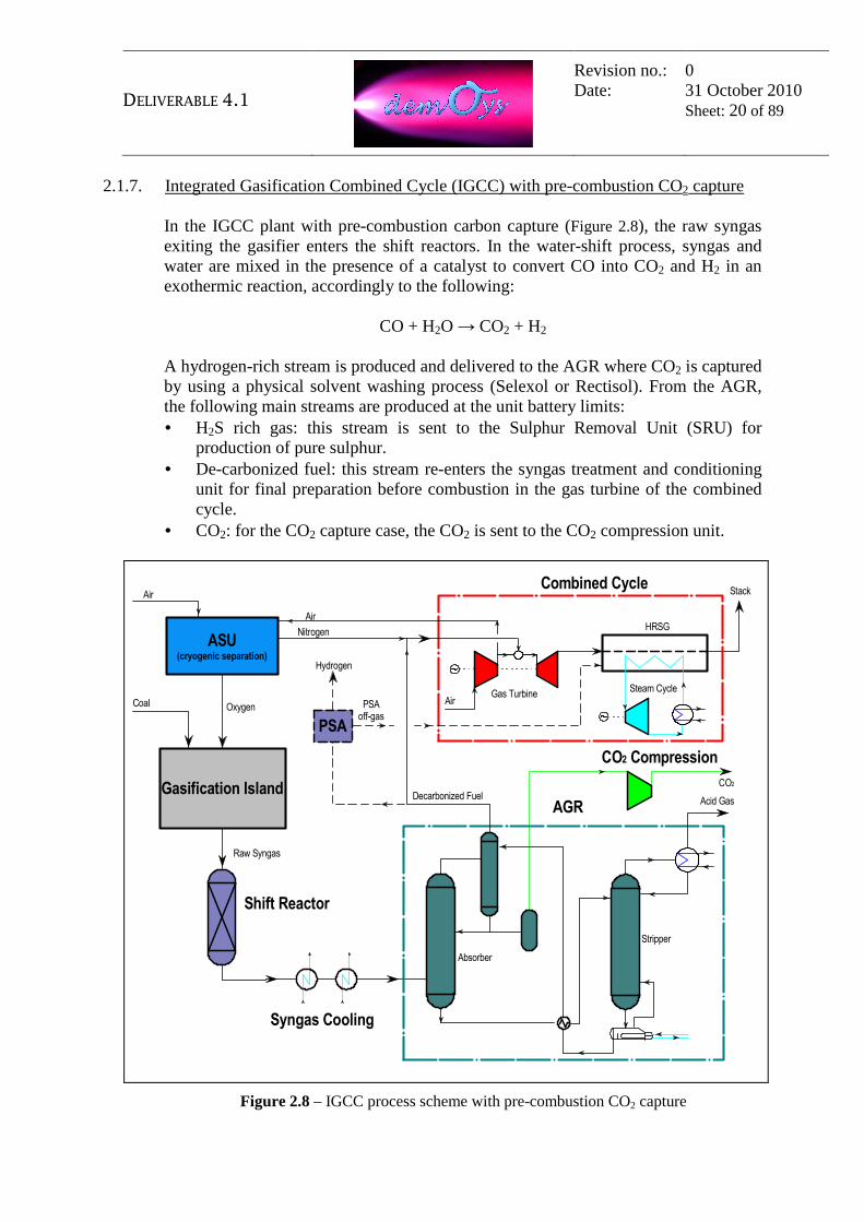
2.1.7. Integrated Gasification Combined Cycle (IGCC) with pre-combustion CO2 capture
In the IGCC plant with pre-combustion carbon capture (Figure 2.8), the raw syngas exiting the gasifier enters the shift reactors. In the water-shift process, syngas and water are mixed in the presence of a catalyst to convert CO into CO2 and H2 in an exothermic reaction, accordingly to the following:
CO + H2O → CO2 + H2 A hydrogen-rich stream is produced and delivered to the AGR where CO2 is captured by using a physical solvent washing process (Selexol or Rectisol). From the AGR, the following main streams are produced at the unit battery limits: • H2S rich gas: this stream is sent to the Sulphur Removal Unit (SRU) for
production of pure sulphur. • De-carbonized fuel: this stream re-enters the syngas treatment and conditioning
unit for final preparation before combustion in the gas turbine of the combined cycle.
• CO2: for the CO2 capture case, the CO2 is sent to the CO2 compression unit.
Acid Gas
Stripper
Absorber
Gasification Island
Combined Cycle
HRSG
Gas TurbineSteam Cycle
Coal
Air
Stack
ASU(cryogenic separation)
AGR
Oxygen
Air
Shift Reactor
Decarbonized Fuel
Raw Syngas
CO2
CO2 Compression
Syngas Cooling
PSA
Hydrogen
PSAoff-gas
Nitrogen
Air
Figure 2.8 – IGCC process scheme with pre-combustion CO2 capture
DELIVERABLE 4.1
Revision no.: Date:
0 31 October 2010 Sheet: 21 of 89
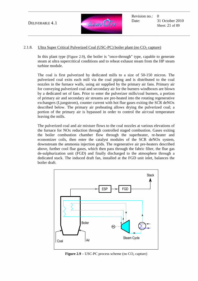
2.1.8. Ultra Super Critical Pulverized Coal (USC-PC) boiler plant (no CO2 capture) In this plant type (Figure 2.9), the boiler is "once-through" type, capable to generate steam at ultra supercritical conditions and to reheat exhaust steam from the HP steam turbine module. The coal is first pulverized by dedicated mills to a size of 50-150 micron. The pulverized coal exits each mill via the coal piping and is distributed to the coal nozzles in the furnace walls, using air supplied by the primary air fans. Primary air for conveying pulverized coal and secondary air for the burners windboxes are blown by a dedicated set of fans. Prior to enter the pulverizer mills/coal burners, a portion of primary air and secondary air streams are pre-heated into the rotating regenerative exchangers (Ljungstrom), counter current with hot flue gases exiting the SCR deNOx described below. The primary air preheating allows drying the pulverized coal; a portion of the primary air is bypassed in order to control the air/coal temperature leaving the mills. The pulverized coal and air mixture flows to the coal nozzles at various elevations of the furnace for NOx reduction through controlled staged combustion. Gases exiting the boiler combustion chamber flow through the superheater, re-heater and economizer coils, then enter the catalyst modules of the SCR deNOx system, downstream the ammonia injection grids. The regenerative air pre-heaters described above, further cool flue gases, which then pass through the fabric filter, the flue gas de-sulphurization unit (FGD) and finally discharged to the atmosphere through a dedicated stack. The induced draft fan, installed at the FGD unit inlet, balances the boiler draft.
Boiler
Steam CycleCoal Air
Stack
ESP FGD
Figure 2.9 – USC-PC process scheme (no CO2 capture)

DELIVERABLE 4.1
Revision no.: Date:
0 31 October 2010 Sheet: 22 of 89
The Steam Turbine is fully reheated, condensing type, fed by ultra-supercritical steam at one pressure level, generated in the USC PC boiler. The ultra-supercritical steam produced by the boiler is admitted in the HP module of the Steam Turbine (ST). Most of the HP module exhaust steam, named Cold Re- Heat (RH), is sent to the boiler for re-heating, while the remaining part is routed to the final exchanger of the BFW preheating line. The reheated steam coming from the boiler is admitted to the MP section of the steam turbine. Some amount of steam is extracted from the MP turbine section to meet the steam demand of the deaerator and the steam turbine driver of the BFW pump; the remainder amount is admitted to the LP section of the steam turbine. The exhaust wet steam from the LP module outlet is discharged into a water-cooled condenser.
2.1.9. USC-PC boiler plant with post-combustion capture With respect to the PC boiler plant without carbon capture (described in the previous section), the exhaust of the boiler before discharge to the atmosphere pass through the post-combustion carbon capture unit, which separates most of the CO2 (Figure 2.10). Absorption in chemical solvents, such as amines, is the most mature technology, already commercially available, though it has not been proven at a large scale yet. The flue gases from the FGD are fed to the absorption tower by a flue gas blower. A lean amine solution, typically Mono-Ethanol-Amine (MEA), counter-currently interacts with the flue gases to absorb the CO2. The clean flue gases continue to the stack. Some of the heat reaction of the solvent with CO2 is removed by the pump around coolers, located at different sections of the column. Before leaving the column, the sweet gas is scrubbed with make-up water to remove the entrained solvent and avoid any dispersion to the atmosphere. From the bottom of the absorption columns, the rich solvent is heated in a regenerative cross exchanger against the hot stripper bottom and sent to the regeneration column, which is composed of a stripping section. LP steam necessary for solvent regeneration comes from the combined cycle, while saturated condensate is pumped back to the deaerator. The vapour at the top of the column passes through the overhead stripper condenser, where it is cooled versus cold condensate from the steam turbine condenser. At the overhead stripper condenser outlet, water vapor is separated generating the rich CO2 stream, which flows to the CO2 compression unit, while condensed water is partially returned to the column as reflux. The lean solvent at the bottom of the stripping column is pumped back to the absorption, after final cooling against cooling water.

DELIVERABLE 4.1
Revision no.: Date:
0 31 October 2010 Sheet: 23 of 89
Boiler
Steam CycleCoal Air
Stack
StripperAbsorber
Power Island
CO2
CO2 Compression
ESP FGD
AGR
Figure 2.10 – USCPC process scheme with post-combustion CO2 capture
2.1.10. Oxy-combustion USC-PC boiler and cryogenic purification
In an oxy-fuel process (Figure 2.11), the fuel combustion is made by utilising almost pure oxygen as oxidising medium. As a consequence, the flue gases are mainly composed of carbon dioxide and other components like water and inerts (excess O2, and N2 and Ar entrained in the oxygen stream delivered from the ASU). Therefore, the carbon dioxide capture process mainly consists of a purification of the flue gases for the removal of these components. The higher is the oxygen purity, the lower is the content of inerts in the flue gases. To moderate peak temperature in the combustion chamber and avoid an increase of the radiant heat pick-up and, part of the flue gas leaving the boiler, around 67% of the original flue gas leaving the economiser, needs to be recirculated back to the burners. Recycled gases are mixed with oxygen from ASU and then supplied to the boiler in two streams:
• Primary recycle: it passes through the coal mills and transports the pulverised coal to the burners. The volumetric flow rate of the primary recycle gas is maintained at a value required for the air firing.
• Secondary recycle: it provides the additional inert gases to the fuel burners in order to keep the furnace temperatures at levels similar to those of the air fired boilers.
The flue gas exiting the boiler is used to heat the primary and secondary recycle flue gas streams via a regenerative gas/gas heater. The flue gas is de-dusted via the ESP. The clean flue gas is then split into two, with one stream forming the secondary recycle and returning back through the gas/gas heater to the burners. The remaining stream is cooled, dried and split again to form primary recycle and CO2 product

DELIVERABLE 4.1
Revision no.: Date:
0 31 October 2010 Sheet: 24 of 89
streams respectively. The primary recycle passes through the gas/gas heater and is delivered to the coal mills. The steam turbine and the regenerative boiling feedwater heating are essentially the same as the conventional USC-PC case.
Primary recycle
Steam Cycle
Air
Power Island
Coal
ASU(cryogenic separation)
Oxygen
Auto-RefrigeratedCO2 Separation
Inertsto Stack
Direct Contact Cooler
CO2
CO2 Compression
ESP
Gas/Gas HeaterSecondary recycle
Figure 2.11 – Oxy combusted USC-PC process scheme with cryogenic CO2 purification
The net flue gas from the boiler island is then passed through the CO2 cryogenic purification which is most efficient technique to remove incondensable contaminants from a highly concentrated CO2 stream. The process considered in the work is an “auto-refrigerated cycle” (Figure 2.12), which uses the same CO2 separated in the plant as working fluid of a refrigerating cycle that provides to flue gases cooling. Although there are not yet many industrial applications this process can be preferred with respect to conventional refrigeration cycles, because of a simpler plant layout and lower investment cost. The flue gas entering the unit is initially cooled and compressed into an inter-cooled two stages compressor to about 30 bar. Compressed carbon dioxide flows through the swing dual bed desiccant dryer, to remove the last traces of water before entering the cold box. The dry gas is fed to the cold box and initially cooled by heat exchange

DELIVERABLE 4.1
Revision no.: Date:
0 31 October 2010 Sheet: 25 of 89
to approximately -28°C in the “warm exchanger” against the evaporating, superheating CO2 streams and the waste streams from the cold exchanger. The cooled feed is sent to a knock-out drum, which divides liquid and vapour phase; the liquid contains part of the CO2 product, while the vapour from the separator still contains a significant fraction of CO2 and almost all the other lighter components present in the flue gas. To further recover the carbon dioxide, the vapour phase is cooled to about –54°C in the “cold exchanger”, very close to the triple point, then flowing to a second knock-out drum. The vapour from the second separator, containing the separated inerts and part of the CO2, is sent back through the two main heat exchangers, where it is heated by cooling the rich CO2 stream entering the unit. After pre-heating and expansion , this stream is finally released to the atmosphere. Both the warm and the cold heat exchangers are made of multi-stream plate-fin aluminium blocks. The liquid phase from the first separator, containing part of the CO2, is throttled through a valve and then heated. The liquid phase from the second separator is heated, throttle through a valve and then separated in a third flash drum. The resulting liquid stream is carbon dioxide at high purity. Because of throttling, the last liquid stream is at a temperature of about –55°C, thus being used as refrigerator in the cold exchanger. The vapour phase from the third separator is compressed and recycled to the cold box inlet. The high-purity CO2 vapour stream leaving the warm exchanger is compressed and mixed with the CO2 stream from the first separator. The two streams are combined and finally compressed for CO2 transportation and storage. In an oxy-fuel process, the low pressure oxygen is provided by a dedicated Air Separation Unit (ASU), which is based on an industry standard method of cryogenic air separation, using a double column distillation cycle. In accordance to the boiler requirements, oxygen is delivered at low pressure, generally slightly higher than the ambient pressure.

DELIVERABLE 4.1
Revision no.: Date:
0 31 October 2010 Sheet: 26 of 89
Figure 2.12 – Auto-refrigerated process scheme for CO2 cryogenic purification

DELIVERABLE 4.1
Revision no.: Date:
0 31 October 2010 Sheet: 27 of 89
2.2. Performance and cost data of benchmark technologies The following Table 2.1 and Table 2.2 summarize the expected performances and cost data of benchmark technologies described in the previous sections. These data shall be deemed as preliminary only and originate from public studies made by Foster Wheeler in the past for international organizations or from studies and conference proceedings that are in the public domain. Data shown in these tables will then be used as a reference for the comparison with the same figures of the membrane-integrated power and hydrogen plants that will be developed during the execution of the DEMOYS project. The performances shown in this tables refer to plants located in a generic European site, with ISO conditions (15°C ambient temperature, Relative Humidity 60% and sea level atmospheric pressure) and water available for cooling of the equipment through conventional cooling towers in closed loop circuit. For the cases with CO2 capture, the carbon dioxide capture rate depends on the technology while the targeted CO2 purity is >95% by volume and final pressure at plant battery limits is 110 barg. For the case generating hydrogen, this is produced with a minimal purity of 99.9% by volume and at a pressure of approximately 22 bara. The followings tables show also the SPECCA (Specific Primary Energy Consumption for CO2 Avoided) coefficient, already introduced in CAESAR project, which identifies the amount of thermal energy required to avoid the emission of one kg of CO2. The SPECCA is defined as follows:
where: η is the plant net electrical efficiency; ηREF is the plant net electrical efficiency of the reference plant without
carbon capture; E is the plant CO2 emission [kgCO2/kWhel]; EREF is the plant CO2 emission [kgCO2/kWhel] of the reference plant without
carbon capture. Reference plant for NG-based power plant is the simple NGCC without CCS. Reference plant for hydrogen plants is the SMR without CCS. For coal-fed boiler plant and IGCC the reference plant is the USC-PC boiler plant without CCS. Regarding the investment costs, they refer to the 3rd Quartile 2010 (3Q10) and the expected accuracy is ± 35%.

DELIVERABLE 4.1
Revision no.: Date:
0 31 October 2010 Sheet: 28 of 89
Table 2.1 – Expected Performance and cost data of benchmark technologies for NG-based plants.
PLANT FEATURES
Plant fuel Natural Gas Natural Gas Natural Gas Natural Gas Natural Gas
Type Combined Cycle Combined Cycle Reforming(3) Steam Reforming Steam Reforming
De-carbonization process N/A(1) Post-combustion Pre-combustion N/A(1) Pre-combustion
CO2 capture technology N/A(1) Solvent washing (MEA)
Solvent washing (MDEA) N/A(1) Solvent washing
(MDEA) Maturity of CO2 capture technology N/A(1) High Very High N/A(1) Very High
PERFORMANCE DATA Feedstock flowrate, t/h 53 53 67 29.5 (4) 28 (4)
Feedstock LHV [kJ/kg] 48,900 48,900 48,900 48,900 48,900
Thermal energy of the feedstock (LHV) [MWth] 720 720 910 400 380
Net electric power output [MWe] 415 357 373 - -
Hydrogen production [Nm3/h] N/A(1) N/A(1) N/A(3) 100,000 100,000
Net electrical efficiency [%, LHV basis] 57.6 49.6 41.0 N/A(1) N/A(1)
CO2 capture rate [%] N/A(1) 90 90 N/A(1) 60
SPECCA [MJLHV/kgCO2] N/A(1) 3.25 8.38 N/A(1) N/A(1)
COST DATA (2) Total Investment Cost (TIC) [M€] 280 393 858 90 120
Specific Investment Cost (SIC) [€/kW] 675 1,100 2,300 N/A(1) N/A(1) NOTES: (1) Not Applicable. (2) Average data from studies and conferences in the public domain. Expected accuracy: +/-35%. (3): Auto Thermal
Reforming or Steam Methane Reforming (SMR) plant for power production only. (4) Flowrate includes NG for reactor feed and for the boiler burners.

DELIVERABLE 4.1
Revision no.: Date:
0 31 October 2010 Sheet: 29 of 89
Table 2.2 – Expected Performance and cost data of benchmark technologies for coal-based plants
PLANT FEATURES
Plant fuel Bituminous Coal Bituminous Coal Bituminous Coal Bituminous Coal Bituminous Coal
Type USC-PC(3) USC-PC(3) IGCC(4) IGCC(4) Oxy-fired USCCP
De-carbonization process N/A(1) Post-combustion N/A(1) Pre-combustion Oxy-combustion
CO2 capture technology N/A(1) Solvent washing (MEA) N/A(1) Solvent washing
(Physical) Cryogenic purification
Maturity of CO2 capture technology N/A(1) High N/A(1) Very High Medium
PERFORMANCE DATA Feedstock flowrate, t/h 234 234 302 317 234
Feedstock LHV [kJ/kg] 25,900 25,900 25,900 25,900 25,900
Thermal energy of the feedstock (LHV) [MWth] 1,684 1,684 2,173 2,279 1,684
Net electric power output [MWe] 749 581 891 775 596
Net electrical efficiency [%, LHV basis] 44.5 34.5 41.0 34.0 35.4
CO2 capture rate [%] N/A(1) 90 N/A(1) 90 95
SPECCA [MJLHV/kgCO2] N/A(1) 3.64 N/A(1) 3.81 3.00
COST DATA (2) Total Investment Cost (TIC) [M€] 1,198 1,755 1,942 2,248 1,746
Specific Investment Cost (SIC) [€/kW] 1,600 2,690 2,180 2,900 2,930 NOTES: (1) Not Applicable. (2) Average data from studies and conferences in the public domain. Expected accuracy: +/-35%. (3) Ultra-Super Critical Pulverized Coal Boiler technology. (4) Integrated Gasification Combined Cycle
DELIVERABLE 4.1
Revision no.: Date:
0 31 October 2010 Sheet: 30 of 89
3. General feature of Ion Transport Membranes
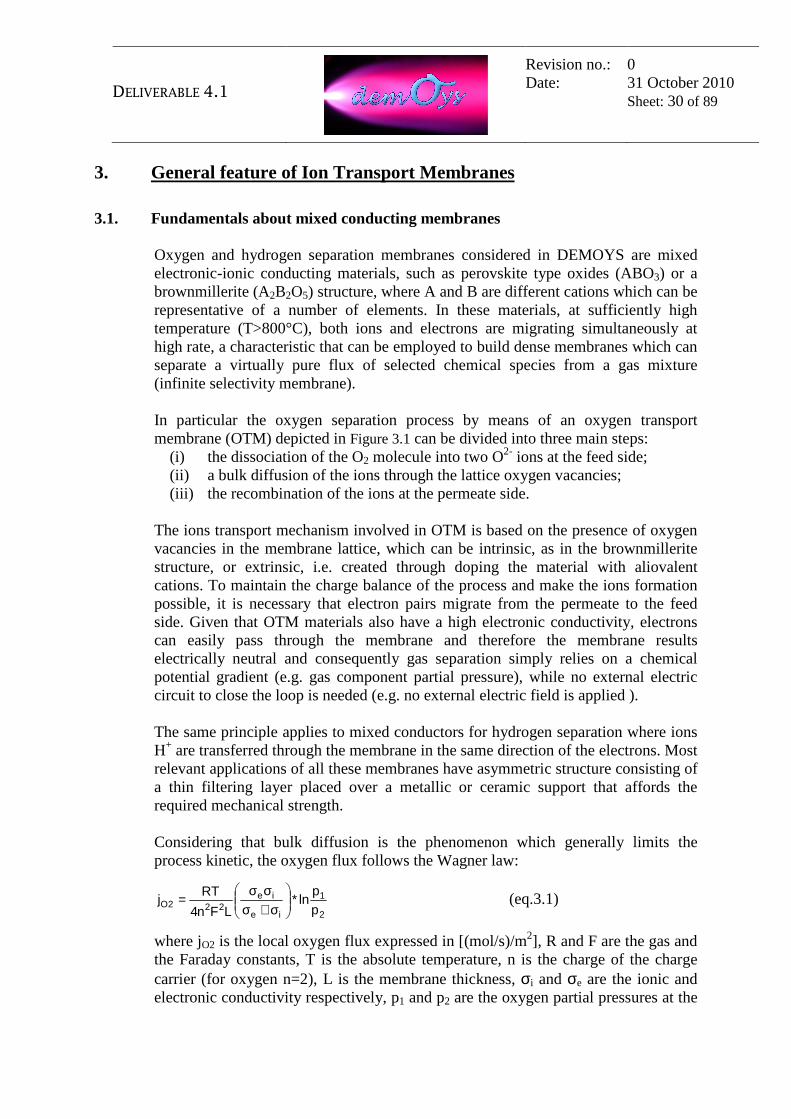
3.1. Fundamentals about mixed conducting membranes Oxygen and hydrogen separation membranes considered in DEMOYS are mixed electronic-ionic conducting materials, such as perovskite type oxides (ABO3) or a brownmillerite (A2B2O5) structure, where A and B are different cations which can be representative of a number of elements. In these materials, at sufficiently high temperature (T>800°C), both ions and electrons are migrating simultaneously at high rate, a characteristic that can be employed to build dense membranes which can separate a virtually pure flux of selected chemical species from a gas mixture (infinite selectivity membrane). In particular the oxygen separation process by means of an oxygen transport membrane (OTM) depicted in Figure 3.1 can be divided into three main steps:
(i) the dissociation of the O2 molecule into two O2- ions at the feed side; (ii) a bulk diffusion of the ions through the lattice oxygen vacancies; (iii) the recombination of the ions at the permeate side.
The ions transport mechanism involved in OTM is based on the presence of oxygen vacancies in the membrane lattice, which can be intrinsic, as in the brownmillerite structure, or extrinsic, i.e. created through doping the material with aliovalent cations. To maintain the charge balance of the process and make the ions formation possible, it is necessary that electron pairs migrate from the permeate to the feed side. Given that OTM materials also have a high electronic conductivity, electrons can easily pass through the membrane and therefore the membrane results electrically neutral and consequently gas separation simply relies on a chemical potential gradient (e.g. gas component partial pressure), while no external electric circuit to close the loop is needed (e.g. no external electric field is applied ). The same principle applies to mixed conductors for hydrogen separation where ions H+ are transferred through the membrane in the same direction of the electrons. Most relevant applications of all these membranes have asymmetric structure consisting of a thin filtering layer placed over a metallic or ceramic support that affords the required mechanical strength. Considering that bulk diffusion is the phenomenon which generally limits the process kinetic, the oxygen flux follows the Wagner law:
2
1
ie
ie222O p
pln*
LFn4
RTj
σ+σσσ
= (eq.3.1)
where jO2 is the local oxygen flux expressed in [(mol/s)/m2], R and F are the gas and the Faraday constants, T is the absolute temperature, n is the charge of the charge carrier (for oxygen n=2), L is the membrane thickness, σi and σe are the ionic and electronic conductivity respectively, p1 and p2 are the oxygen partial pressures at the

DELIVERABLE 4.1
Revision no.: Date:
0 31 October 2010 Sheet: 31 of 89
feed and at the permeate sides. Substituting n=2 and considering that electronic conductivity is generally much higher than the ionic one, the Wagner equation can be rewritten as:
2
1
2
12
i2O p
pln*
LPe
pp
ln*LF16
RTj =σ= (eq.3.2)
where Pe is membrane permeability, a characteristic of the separating film material. Temperature is one of the parameters that mainly influences the permeability and, provided that the process is thermally activated, it is typically carried out in the temperature range of 800-1000°C. The membrane thickness is another important parameter: for values higher than a critical thickness (below that the limiting step becomes the surface exchange and the Wagner equation is no longer applicable), the oxygen flux show a linear dependence with respect to the reciprocal thickness (1/L). The O2 partial pressure ratio is the driving force, influencing the flux according to a logarithmic trend. Consequently, given an assigned pressure on the permeate side, the oxygen flux can be enhanced by increasing the total pressure of the air stream on the feed side and, if pure O2 is not required, by using a sweep gas on the permeate side in order to dilute the oxygen stream.
pressurized air feed
O 2- electrons separating
layer L
½O 2 + 2e - →→→→ O 2-
O 2- → → → → ½O 2 + 2e -
oxygen-depleted non-permeate
low pressure high-purity oxygen product
Figure 3.1 – Oxygen transport membrane concept [1]
In Figure 3.2 a schematic diagram for a generic mixed conducting membrane is presented. From the feed stream a fraction of the "selected" chemical species (in our case either O2 or H2) permeates across the membrane, while the remaining components included in the mixture exit the membrane as retentate. On the other side, optionally a second stream can be fed to the membrane, acting as a “sweep gas” in order to lower the partial pressure of the "selected" species, increasing the driving force for its permeation and thereby reducing the required membrane surface for an assigned stream total pressure. The sweep gas stream is enriched with the “selected” component and exits the membrane as permeate.

DELIVERABLE 4.1
Revision no.: Date:
0 31 October 2010 Sheet: 32 of 89
Permeate Sweep gas
Feed Retentate
"Selected" component
Figure 3.2 – Generic mixed conducting membrane simplified scheme
Reference [1] Allam R.J., Russek S.L., Smith A.R., Stein V. “Cryogenics & Ceramic Membranes: Current & Future Technologies for Oxygen Supply in Gasification Systems”, 4th European Gasification Conference, April 2000, Noordwijk, The Netherlands
3.2. Fundamentals about membrane reactors.
As outlined before a membrane allows a selective permeation of chemical species across a separating layer. If no chemical reactions occur either on feed or retentate side the component that accomplishes gas separation is called "permeator", while in case reactions occur on the feed and/or retentate side that component is called "membrane reactor". Membrane reactors can be arranged upon different geometries according to the different requirements:
− chemical species permeated through the membrane; − operating temperatures; − heat transfer from/to the reacting streams. Optionally heat could also be
transferred across the membrane between the feed and permeate streams. Nevertheless this choice may lead to a mismatch between surfaces required to transfer mass and heat and, in case the second exceeds the first one, to oversize the membrane area. Due to this problem, in the following selection of plants configuration, preference will be given to the ones where heat exchange to the reacting stream does not rely upon heat transfer across the membranes.
According to [2], high temperature membrane technologies applicable to power generation and H2 production processes can be summarized as follows:
• Microporous membranes for H2 separation, currently suffering from stability against sintering at temperatures over 400 °C, particularly in water vapor containing atmospheres;
• Dense palladium based membranes for H2 separation operating in the range 300-500 °C;
DELIVERABLE 4.1
Revision no.: Date:
0 31 October 2010 Sheet: 33 of 89
• Dense electrolytes and mixed conducting (ionic and electronic) membranes
for O2 or H2 separation operating in the range 800-1000°C, the ones investigated in the DEMOYS project.
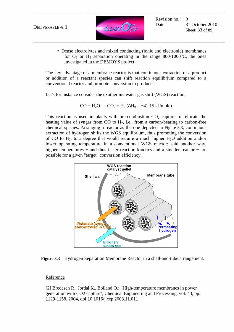
The key advantage of a membrane reactor is that continuous extraction of a product or addition of a reactant species can shift reaction equilibrium compared to a conventional reactor and promote conversion to products. Let's for instance consider the exothermic water gas shift (WGS) reaction:
CO + H2O → CO2 + H2 (∆H0 = −41.15 kJ/mole) This reaction is used in plants with pre-combustion CO2 capture to relocate the heating value of syngas from CO to H2, i.e., from a carbon-bearing to carbon-free chemical species. Arranging a reactor as the one depicted in Figure 3.3, continuous extraction of hydrogen shifts the WGS equilibrium, thus promoting the conversion of CO to H2, to a degree that would require a much higher H2O addition and/or lower operating temperature in a conventional WGS reactor; said another way, higher temperatures − and thus faster reaction kinetics and a smaller reactor − are possible for a given "target" conversion efficiency.
WGS reactioncatalyst pellet
NitrogenNitrogensweep gassweep gas
Shell wall
Retenate (syngas Retenate (syngas concentrated in COconcentrated in CO22)) Permeating
hydrogen
Membrane tube
Figure 3.3 – Hydrogen Separation Membrane Reactor in a shell-and-tube arrangement.
Reference [2] Bredesen R., Jordal K., Bolland O.: "High-temperature membranes in power generation with CO2 capture", Chemical Engineering and Processing, vol. 43, pp. 1129-1158, 2004, doi:10.1016/j.cep.2003.11.011

DELIVERABLE 4.1
Revision no.: Date:
0 31 October 2010 Sheet: 34 of 89
3.3. Integration of oxygen and hydrogen separation membrane in power/H2 plants
Table 3.1 shows the potential integration of the oxygen and/or hydrogen separation membranes in the power and/or H2 plants with reference to the benchmark CCS plant configurations discussed in the previous section. Generally speaking, the role of OTM is to deliver pure oxygen to the fuel combustion reactor, whether it is a gasifier burner or a reformer reactor, depending on plant type. On the other hand, the hydrogen separation membrane can mainly be adopted for the separation of H2 and from syngas (reforming and shift reactions may eventually occur in integrated membrane-reactors).
Table 3.1 – Potential integration of oxygen and hydrogen separation membrane in power/H2 plants with CCS.
Plant type Output O2 Membranes H2 Membranes
C O A L
IGCC
Power (H2)
Provide O2 to the gasifier
-
Power (H2)
Provide O2 to the gasifier
Separate H2 from syngas
Oxy-fuel Boiler Power Provide O2 to the
boiler -
N A T U R A L
G A S
Oxy-fuel NGCC Power Provide O2 to the NG combustion
-
SMR (1) H2
(Power) -
H2 separation membrane-reformer
ATR (2)
H2 (Power)
Provide O2 to the reforming reactor
-
H2 (Power)
Provide O2 to the reforming reactor
H2 separation membrane-reformer
H2 (Power)
H2 separation membrane-reformer integrated with O2 membranes
NOTE: (1) Steam Methane Reformer. (2) Methane Auto-Thermal Reformer fed with oxygen. Section 4 and 5 summarize the results of literature research made to investigate possible plant configurations, while section 6 makes a preliminary selection of plant alternatives made from the cases shown in Table 3.1. The selected configurations will be further developed in the DEMOYS project.

DELIVERABLE 4.1
Revision no.: Date:
0 31 October 2010 Sheet: 35 of 89
4. Mapping of membrane integrated coal based power plants from
literature This section makes a mapping of the plant configurations proposed in the scientific literature and research projects, which could be suitable for integration of the membrane technology in power and hydrogen generation plants fed with coal. The plant configurations shown in these sections will then be used to make a preliminary selection of industrial process schemes that can be of potential interest for future applications of hydrogen and oxygen separation membranes that are object of the DEMOYS project (refer to section 6).
4.1. Integrated Gasification Combined Cycle (IGCC) Cryogenic distillation for oxygen and nitrogen separation in Air Separation Units (ASU) is mature and reliable technology, but it represents ~15% of plant capital costs and consumes ~15% of the IGCC gross power output, producing 95% pure oxygen [Stein 2009]. On the other hand, oxygen transport membrane technology is also well positioned to meet clean energy generation needs. It produces higher purity oxygen (>99%) in compact volume and requires much less parasitic power (mainly for the air compression) than cryogenic ASU. The main results of the study made by Stein are summarized in Table 4.1, showing that IGCC+OTM performs slightly better than IGCC+ASU (0.5 percentage point efficiency gain). Apart from savings in oxygen plant cost, net power output of IGCC+OTM is 84MW higher than IGCC+ASU. Generally in literature is stated that installed capital cost of OTM oxygen plant decreases in comparison to cryogenic ASU by 1/3rd [Air Products, 2002] to 1/4th [Stein 2009] and capital cost of IGCC by 7% [Air Products, 2002] to 9% [Stein 2009]. Moreover power requirements for air separation unit is reduced by 35%.
Table 4.1 – Air Products system design specifications with alternative ASU technologies [Stein 2007]
Cryogenic ASU OTM membrane Net output MW 543 627 Net efficiency, %HHV 38.4 38.9 Oxygen plant cost ($/ TPD O2) 25000 18700 IGCC Specific Capital Cost ($/kW) 1500 1368
*OTM oxygen plant capacity 4,550 sTPD oxygen + 13,200 sTPD diluent
Several options have been considered for the OTM Air Products system integration with the Siemens SGT6-6000G 300 MW gas turbine, including boost compressor, recuperator use and vitiated air temperature. The best cost per kW and HHV efficiency (almost 40%) has been calculated for the boost compressor/recuperator combination.

DELIVERABLE 4.1
Revision no.: Date:
0 31 October 2010 Sheet: 36 of 89
Figure 4.1 – Integration of OTM with boost compressor/recuperator which minimizes GT design impact [Stein, 2007]
Air Products OTM planar stack modules operates with capacity of 0.5-1 ton O2/day (at 99% purity) and it are tested in a pilot plants with capacity of ~6 ton/day [Stein 2009]. Intermediate-scale test unit at 150 ton O2/day are planned for operation in 2011. Table 4.2 presents a rough estimate of the costs for both a large-scale oxygen production (30 000 Nm3/h) and a small-scale system (1 500 Nm3/h). The difference between Total process equipment and Total fixed capital is caused by including percentages, for example, piping, installation, and engineering, following standard cost engineering procedures. Total process equipment is the sum of single units in each system.
HRSG
RECUPERATOR
AIR
OXYGEN
AIR
Siemens SGT6-6000G
~300 MW
ITM-SPECIFIC GAS TURBINE
STEAM
ELECTRIC
SYNGAS
BOOST COMP’R
SYNGAS
OXYGEN COMP’R
OXYGEN SUPPLY to GASIFIER
OXYGEN COOLING
OXYGEN TRANSPORT MEMBRANE

DELIVERABLE 4.1
Revision no.: Date:
0 31 October 2010 Sheet: 37 of 89
Table 4.2 – Breakdown of total fixed capital for large and small-scale OTM systems (the HRSG
is not used in the latter system) [Exter, 2009]
# k€ # k€ Investments Large-scale Small-scale 30000 Nm3/h 1500 Nm3/h PERFORMANCE Process equipment Heat exchangers 3 362 2 112 Oxygen compressor 1 1530 1 18 Membrane module shells 38 7692 1 385 Burners (or modification) 2 200 2 60 Gas turbine + HRSG 1 33724 1 1100 Membrane tubes* 7500 375 Total process equipment 51008 2050 Total fixed capital 101949 4695 ECONOMIC EVALUATION (M€/year) (M€/year) Costs Variable costs 12.3 0.490 Fixed costs 9.2 0.460 Admn. And sales 0.2 0.040 Total 21.5 0.970 Revenues Oxygen 13.5 1.09 Electricity 13.6 0.280 Total 27.1 1.360 Cash Flow 5.5 0.400 Simple Pay Out Time 16.8 years 11.0 years
*oxygen flux taken: 10 ml/cm2 min
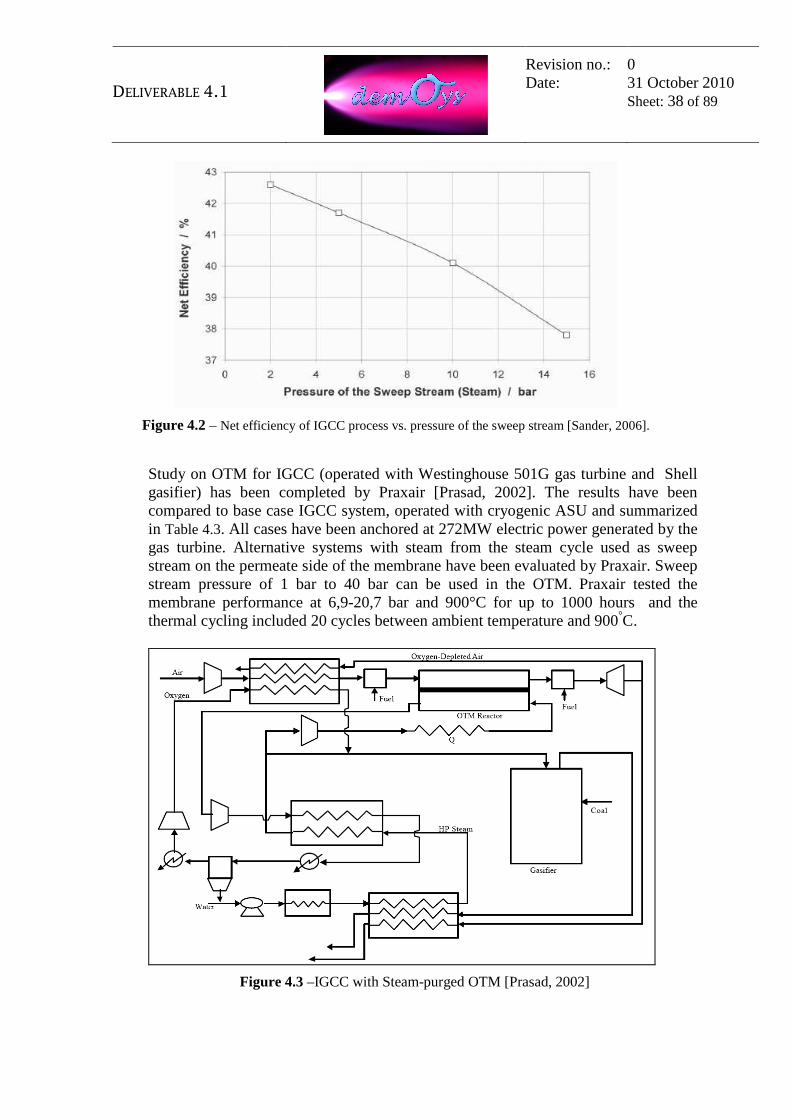
Pressure on the permeate side of the membrane has tremendous influence on the overall efficiency of the power generation process with the integrated OTM reactor. An increase in the pressure of the sweep streams is associated with a rise in temperature because the steam is taken from the intermediate pressure steam turbine which lowers the steam section power output. Figure 4.2 describes in detail this trend.
DELIVERABLE 4.1
Revision no.: Date:
0 31 October 2010 Sheet: 38 of 89
Figure 4.2 – Net efficiency of IGCC process vs. pressure of the sweep stream [Sander, 2006].
Study on OTM for IGCC (operated with Westinghouse 501G gas turbine and Shell gasifier) has been completed by Praxair [Prasad, 2002]. The results have been compared to base case IGCC system, operated with cryogenic ASU and summarized in Table 4.3. All cases have been anchored at 272MW electric power generated by the gas turbine. Alternative systems with steam from the steam cycle used as sweep stream on the permeate side of the membrane have been evaluated by Praxair. Sweep stream pressure of 1 bar to 40 bar can be used in the OTM. Praxair tested the membrane performance at 6,9-20,7 bar and 900°C for up to 1000 hours and the thermal cycling included 20 cycles between ambient temperature and 900°C.
Figure 4.3 –IGCC with Steam-purged OTM [Prasad, 2002]

DELIVERABLE 4.1
Revision no.: Date:
0 31 October 2010 Sheet: 39 of 89
Table 4.3 – IGCC systems with alternative ASU technologies (Praxair) [Prasad, 2002]
Cryogenic APU
OTM membrane
Air supply Compressed air from GT Air heating fuel fuel Oxygen stream, TPD 2423 2448 Oxygen purity 95% >99% Net power MWe (gas/steam turbine + misc. Power)
404,9 419.9
Efficiency (% HHV) 44.8 45.9 ASU unit cost (Cayo=100%) 100% 75% IGCC cost ( $MM) 569 551.6 Capital cost ($/kW) 1407 1314 Cost of energy ($/MWh) 51.9 48.9
The integration of hydrogen transport membranes in IGCC plants has been analyzed in different papers. As shown in par 3.2, membranes are integrated in the high temperature water gas shift reactor so that continuous H2 extraction promotes CO conversion. Since presence of solids and poisoning compounds, such as heavy metals, may damage membranes reactors, they have to be placed downstream the water scrubber and potentially (depending on membrane capability to tolerate it) sulfur removal. Moreover, operating temperature of membranes and shift catalyst should be well-matched in the same temperature range (350÷450 °C) and therefore microporous or dense Pd–based alloy membranes are considered for this task. The mixed conducting membranes that are object of the DEMOYS project work at high operating temperatures (approx. 800°-1000°C), thus leading to a non-efficient process as the syngas should be re-heated after solids and sulphur removal. For this reason, the application of hydrogen transport membranes in IGCC plants is not taken into consideration in the DEMOYS project.
4.2. Oxy-fired plants In the past years, process concepts incorporating ceramic oxygen transport membranes (OTM) into coal-fired power plants in order to facilitate carbon dioxide capture have undergone technical and economic evaluation. The oxy-combustion process is one of several proposed methods to capture CO2 from coal fired power plants, taking advantage from the high CO2 concentration in the flue gases. In an air-blown boiler retrofit situation, pure oxygen would replace air required for combustion, and the oxygen would likely be supplied via an air separation unit (ASU). The implementation of OTM in this plant avoids the use of cryogenic ASU, which presents high investment cost and has a high power demand, as mentioned in the previous section.
DELIVERABLE 4.1
Revision no.: Date:
0 31 October 2010 Sheet: 40 of 89
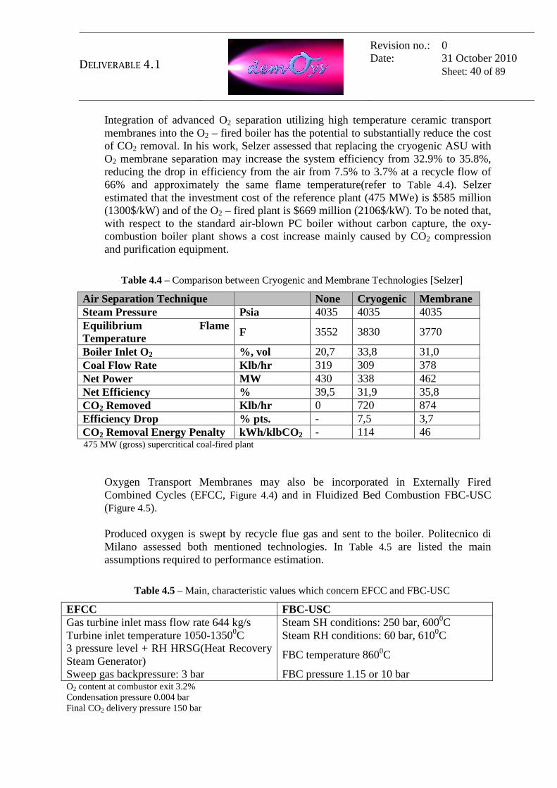
Integration of advanced O2 separation utilizing high temperature ceramic transport membranes into the O2 – fired boiler has the potential to substantially reduce the cost of CO2 removal. In his work, Selzer assessed that replacing the cryogenic ASU with O2 membrane separation may increase the system efficiency from 32.9% to 35.8%, reducing the drop in efficiency from the air from 7.5% to 3.7% at a recycle flow of 66% and approximately the same flame temperature(refer to Table 4.4). Selzer estimated that the investment cost of the reference plant (475 MWe) is $585 million (1300$/kW) and of the O2 – fired plant is $669 million (2106$/kW). To be noted that, with respect to the standard air-blown PC boiler without carbon capture, the oxy-combustion boiler plant shows a cost increase mainly caused by CO2 compression and purification equipment.
Table 4.4 – Comparison between Cryogenic and Membrane Technologies [Selzer]
Air Separation Technique None Cryogenic Membrane Steam Pressure Psia 4035 4035 4035 Equilibrium Flame Temperature F 3552 3830 3770
Boiler Inlet O2 %, vol 20,7 33,8 31,0 Coal Flow Rate Klb/hr 319 309 378 Net Power MW 430 338 462 Net Efficiency % 39,5 31,9 35,8 CO2 Removed Klb/hr 0 720 874 Efficiency Drop % pts. - 7,5 3,7 CO2 Removal Energy Penalty kWh/klbCO 2 - 114 46 475 MW (gross) supercritical coal-fired plant
Oxygen Transport Membranes may also be incorporated in Externally Fired Combined Cycles (EFCC, Figure 4.4) and in Fluidized Bed Combustion FBC-USC (Figure 4.5). Produced oxygen is swept by recycle flue gas and sent to the boiler. Politecnico di Milano assessed both mentioned technologies. In Table 4.5 are listed the main assumptions required to performance estimation.
Table 4.5 – Main, characteristic values which concern EFCC and FBC-USC
EFCC FBC-USC Gas turbine inlet mass flow rate 644 kg/s Steam SH conditions: 250 bar, 6000C Turbine inlet temperature 1050-13500C Steam RH conditions: 60 bar, 6100C 3 pressure level + RH HRSG(Heat Recovery Steam Generator)
FBC temperature 8600C
Sweep gas backpressure: 3 bar FBC pressure 1.15 or 10 bar O2 content at combustor exit 3.2% Condensation pressure 0.004 bar Final CO2 delivery pressure 150 bar

DELIVERABLE 4.1
Revision no.: Date:
0 31 October 2010 Sheet: 41 of 89
Apart from obvious correlation between size and cost of unit, there are many other interdependent properties, which need to be optimized in the plant design. Parameters that mainly influence the OTM-based plant are listed in Table 4.6.
Table 4.6 – Main parameters that affect OTM-based plant design
OTM size and cost
• Permeate pressure • Feed pressure • Fraction removed from the air flow • Recirculation rate of boiler exhaust (exhaust used as sweep gas / total
FC exhausts) [FBC case]
Balance of plant cost
• fraction of oxygen removed from the airflow (as this fraction reduces at the same oxygen flow rate, larger airflow is required and consequently larger turbine, larger compressor, larger exchangers, etc.)
• recirculation rate of boiler exhaust (lower gas flow rate, smaller heat exchangers, smaller compressor) [FBC case]
Gas turbinecompressor
RH+IPsteam
steam turbine
LPsteam
~
CO2 tostorage CO2 compressor
and drier
~
oxygen depleted air
gas turbineexpander
heat recovery steam generator
gypsum
limestone
WetFGD
inlet air
~
HP
bfw
HP
steam
coal
oxygen + sweep gas
OTMMHX CHXoxygen
depletedair
exhaust gas
recirculatingsweep gas
~
Figure 4.4 – Externally Fired Combined Cycles (EFCC) [Romano, 2005]

DELIVERABLE 4.1
Revision no.: Date:
0 31 October 2010 Sheet: 42 of 89
coal +sorbent
inlet air
oxygendepleted
air
OTM
exhaust flow
recirculatingsweep gas
oxygen +sweep gas
heat to steam cycle
CO2 compressor
and drier
MHX
~heat
recovery
heat recovery
FBC
Turbocharger
Figure 4.5 – Fluidized bed combustion USC (basic scheme) [Romano, 2005].
Realization of EFCC cycles relies on the availability of high temperature ceramic heat exchangers (CHX) that are the major technological hurdle of this process configuration. Use of sweep gas greatly helps to reduce membrane area and cost. Therefore, for both EFCC and FBC-USC processes, gas filtration can be a secondary technological hurdle. Data in Table 4.7 describe cryogenic oxy-fuel plant, FBC with OTM technology, IGCC and EFCC with OTM, as estimated by Romano. Comparison between FBC+OTM and IGCC with CO2 capture has revealed that FBC+OTM has higher efficiency and higher environmental performance (100% CO2 captured). However, cost of electricity is similar or higher due to the higher capital costs. Near term reduction in capital cost for FBC and in operating cost for OTM, will make this technology more competitive.

DELIVERABLE 4.1
Revision no.: Date:
0 31 October 2010 Sheet: 43 of 89
Table 4.7 – Comparison between chosen technologies [Romano, 2005]
USC Rankine cycle IGCC Quench EFCC Cryogenic oxyfuel
FBC+ OTM
No capture Selexol CO2 capture
OTM
PERFORMANCE LHV coal input, MW 985.0 985.0 908.2 983.7 528.5 Net power output, MW 348.5 407.2 390.1 361.9 237.5 Net LHV efficiency, % 35.38 41.34 42.95 36.79 44.94 CO2 capture efficiency, % of fuel C
100 100 0 91.28 100
Specific CO2 emissions, g/kWh
0 0 752 70.1 0
ECONOMIC EVALUATION Overnight capital cost, $/kWh 1917 1650÷1900 1187 1531 1500÷1800 COE: Capital, c/kWh 4.61 3.97÷4.57 2.86 3.68 3.61÷4.33 COE: O&M, c/kWh 0.82 0.71÷0.81 0.51 0.66 0.64÷0.77 COE: Fuel, c/kWh 1.56 1.33 1.28 1.5 1.23 COE: CO2 disposal, c/kWh 0.47 0.4 0 0.41 0.37 COE: Total, c/kWh 7.46 6.41÷7.12 4.65 6.25 5.85÷6.70 Cost of CO2 captured*, $/tone 30.6 22.7÷31.5 20.1 17.0÷28.5 Cost of CO2 avoided*, $/tonne 38.6 24.5÷34.0 25.0 16.9÷28.4
Main assumption: Capital charge rate: 15% year Capital factor 7000 h/y Coal price 1.5 $/GJ
Interest during construction 12.3% Annual O&M 3% of the plant cost CO2 disposal 5 $/tonne Yearly efficiency penalty 2%

DELIVERABLE 4.1
Revision no.: Date:
0 31 October 2010 Sheet: 44 of 89
4.3. Summary findings from literature mapping Several literature positions state that proper integration of oxygen membranes technology instead of cryogenic ASU gives additional savings in power costs. The study performed by Air Products, summarized in Table 4.8, presents data, which concerns savings due to integration of OTM technology instead of Cryogenic. In case of capital cost for CO2, it equals respectively: 35% for IGCC and 48% for oxy-fuel. Additionally, Table 4.9 summarizes main technological aspects of oxygen membranes integration with coal power generation plants. Generally, each technology has its own demands and restrictions, but main membrane working conditions do not change. However, capacity, pressure, flow rates of feed and sweep gas streams must be optimized in order to meet the specific demand of coal power generation plant. Unfortunately, power plants differs between each other so there are no universal tips. Optimization of OTM integration in these two technologies process must be done each time.
Table 4.8 – Cost saving of OTM technology with respect to Cryogenic ASU [Armstrong, 2004]
Product Savings (% of Cryo ASU) Application Oxygen
(sTPD) Power (MW)
Capital for Oxygen
Power for Oxygen
IGGC 3200 458 35% 37% Oxyfuel 8030 500 48% 68%
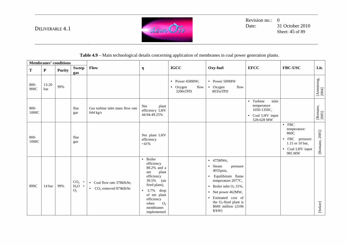
DELIVERABLE 4.1
Revision no.: Date:
0 31 October 2010 Sheet: 45 of 89
Table 4.9 – Main technological details concerning application of membranes in coal power generation plants.
Membranes’ conditions Flow η IGCC Oxy-fuel EFCC FBC-USC Lit.
T P Purity Sweep gas
800-900C
13-20 bar
99%
• Power 458MW;
• Oxygen flow 3200sTPD
• Power 500MW
• Oxygen flow 8035sTPD
[Arm
stro
ng
, 2
004
]
800-1000C
flue gas
Gas turbine inlet mass flow rate 644 kg/s
Net plant efficiency LHV 44.94-49.25%
• Turbine inlet temperature 1050-1350C,
• Coal LHV input 528-628 MW
[Ro
man
o,
20
05]
800-1000C
flue gas
Net plant LHV efficiency ~41%
• FBC temperature: 860C
• FBC pressure: 1.15 or 10 bar,
• Coal LHV input 985 MW [R
om
ano
, 200
5]
899C 14 bar 99% CO2 + H2O + O2
• Coal flow rate 378klb/hr,
• CO2 removed 874klb/hr
• Boiler efficiency 88.2% and a net plant efficiency 39.5% (air fired plant),
• 3.7% drop of net plant efficiency when O2 membranes implemented
• 475MWe,
• Steam pressure 4035psia,
• Equilibrium flame temperature 2077C,
• Boiler inlet O2 31%,
• Net power 462MW,
• Estimated cost of the O2-fired plant is $669 million (2106 $/kW)
[Sel
zer]

DELIVERABLE 4.1
Revision no.: Date:
0 31 October 2010 Sheet: 46 of 89
Membranes’ conditions
Flow η IGCC Oxy-fuel EFCC FBC-USC Lit. T P Purity
Sweep gas
900 19 bar >99% • Oxygen 2448 TPD,
• Coal 2312 TPD. • System
45.9% HHV
• Westinghouse 501G gas turbine (GT),
• Shell gasifier,
• GT power output ~272MW,
• Steam turbine power 198.8 MWe,
• Capital cost of IGCC with OTM 1314 $/kW
[Pra
sad
US
Pat
ent 5
,935
,29
8]
O2 + flue gas (mainly CO2)
• Coal flow Rate 552 M lb/hr;
• Oxygen flow 1146 M lb/hr
• Net efficiency 31.6%;
• Gross power 793
MWe; Net power 573MWe;
[Sel
zer,
2
009
]

DELIVERABLE 4.1
Revision no.: Date:
0 31 October 2010 Sheet: 47 of 89
Membranes’ conditions
Flow η IGCC Oxy-fuel EFCC FBC-USC Lit. T P Purity
Sweep gas
900 fsteam
Modeling work assumption:
• Strong dependence of oxygen permeation flow rate on the sweep stream mass flow rate; the pressure on the permeate side of the membrane is 10 bar.
• Feed air flow rate 150 kg/s.
• The overall surface of the membrane is 30 000 m2.
• At the 900C, oxygen permeation flow changes (from 0.12 up to 0.19 kmol/s) with mass flow sweep (from 4 up to 10% of feed flow).
• Net efficiency drops form 42.5 to 38% with the increase in pressure of the sweep stream: from 2 to 15 bar.
[San
der
, 200
6]
* TPD – tones per day, * IGCC – Integrated Gasification Combined Cycle, * EECC – Externally Fired Combined Cycles, * FBC – Fluidized Bed Combustion, * FBC-USC - Fluidized Bed Combustion Ultrasupercritical
DELIVERABLE 4.1
Revision no.: Date:
0 31 October 2010 Sheet: 48 of 89
4.4. References
1. A.C. Bose, “Inorganic Membranes for Energy and Environment Applications”, Chapter 2; “Viability of ITM Technology for Oxygen Production and Oxidation Processes: Material, System, and Process Aspects”, M.J. den Exter, W.G. Haije, J.F. Vente, 2009.
2. A.H. Selzer, Z. Fan, T. Fout, “An Optimized Supercritical Oxygen – Fired Pulverized Coal Power Plant for CO2 Capture”.
3. Air Products, Project Facts - Development of ITM Oxygen Technology for Integration in IGCC and Other Advanced Power Generation, US DoE, NETL, 2002.
4. Prasad R. et al., Advances in OTM Technology for IGCC, 2002, Praxair
5. Selzer, Z. Fan, “Conceptual Design of Oxygen-Based PC Boiler”, September 2005, OSTI ID 861886.
6. F. Sander, R. Span, “Modelling of an oxygen transport membrane for an IGCC process with CO2 capture”, Thermodynamics and Energy Technologies (ThEt), University of Paderborn D-33095, Germany, 2006.
7. M. Romano, S. Napoletano, P. Chiesa, S. Consonni, “Capture and Separation – Oxyfuel Combustion”, May 2-5, 2005.
8. Nitin Keskar, Ravi Prasad, Christian Gottzmann, “Solid Electrolyte Ionic Conductor With Adjustable Steam-Oxygen Production”, US Patent 5,964,922.
9. Nitin Keskar, Ravi Prasad, Christian Gottzmann, “Solid Electrolyte Ionic Conductor Oxygen Production With Power Generation”, US Patent 5,954,859.
10. Nsakala ya Nskala, G. N. Liljedahl, “Greenhouse Gas Emissions Control by Oxygen Firing in Circulating Fluidized Bed Boilers: Phase 1 – a Preliminary Systems Evaluation”, May 2003, OSTI ID 825796.
11. P.A. Armstrong, D. L. Bennett, E.P. Foster, V.E. Stein, “ITM Oxygen for Gasification”, Air Products, Gasification Technologies 2004.
12. Prof.A. Sarofim, “Oxy-fuel Combustion: Progress and Remaining Issues” , University of Utah, International Oxy-Combustion Research Network, 25-26 January 2007.
13. P. Chiesa, G. Lozza, M. Romano, “Oxygen Transport Membrane and Fluidized Bed Combustion For Low-CO2 Emission Coal Fired Power Plants”, Politechnico di Milano, Energy Department Second international Conference on Clean Coal Technologies for our Future 10-12 May 2005, Sardinia, Italy.
14. Profesor Terry Wall and Dr Jianglong Yu, “Fundamentals of Fluidised-Bed Oxyfuel Combustion”, APP OFWG capacity building course, Thurs/Friday 5/6 February 2009, Daejon, Korea.

DELIVERABLE 4.1
Revision no.: Date:
0 31 October 2010 Sheet: 49 of 89
15. Ravi Prasad, Christian Gottzmann, “Solid Electrolyte Ionic Conductor Oxygen
Production With Steam Purge”, US Patent 5,935,298.
16. Stein E., Armstrong P., Foster T., Bennett D., ITM Oxygen: Taking the Next Step, Gasification Technologies 2009, Colorado Springs, USA, 2009.
17. Stein E., Armstrong P., Foster T., New Gas Turbine Integration Option fot ITM Oxygen in Gasification Applications, Gasification Technologies 2007, San Francisco, USA, 2007.

DELIVERABLE 4.1
Revision no.: Date:
0 31 October 2010 Sheet: 50 of 89
5. Mapping of membrane integrated natural gas-based power plants from literature This section makes a mapping of the plant configurations proposed in the scientific literature and research projects, which could be suitable for integration of the membrane technology in power and hydrogen generation plants fuelled with natural gas. The plant configurations shown in these sections will then be used to make a preliminary selection of industrial process schemes that can be of potential interest for future applications of hydrogen and oxygen separation membranes that are object of the DEMOYS project (refer to section 6).
5.1. Oxy-fuel NGCC integrated with oxygen separation membranes Oxy-combustion of natural gas in power generation systems has been widely studied, though there are no large-scale commercial plants yet. The oxy-combustion process requires pure oxygen that is generally provided by a well-known standard cryogenic air separation unit (ASU). This oxygen plant can be replaced by the use of Oxygen Transport Membranes. The following options have been proposed for the architecture of the MCM reactor, requiring different working conditions for the OTM: • Separate component configuration: natural gas combustion, heat exchange and
oxygen production are carried out in separate components, like in the plant proposed by Colombo and Bolland [3], shown in Figure 5.1. A natural gas oxy-combustor, pre- and post-membrane ceramic heat exchangers and an OTM are hence used.
• Semi-separate component configuration: natural gas combustion is carried out in a separate oxy-combustor, while air separation and high temperature heat exchange are carried out in the same component, like in the plant proposed by Griffin et al. [1] (Figure 5.2). With this configuration, good heat transfer properties are hence required for the OTM.
• Single component configuration: natural gas combustion, heat transfer and oxygen production are carried out within the same component as proposed by Sundkvist et al. [4] (Figure 5.3). In such conditions, ability to withstand to chemically reactive environment and high local temperatures is needed for the material.

DELIVERABLE 4.1
Revision no.: Date:
0 31 October 2010 Sheet: 51 of 89
Figure 5.1 – Schematic of the plant proposed by Colombo and Bolland [2], where heat transfer, oxygen separation and combustion in MCM reactor are carried out in separate
components.
The schematic of the AZEP (Advanced Zero Emissions Power Plant) cycle (Semi-separate component configuration) is shown in Figure 5.2. Most of the air exiting the compressor of a gas turbine is sent to the MCM (Mixed Conducting Membrane) reactor. Here, air is heated up to about 800°C and 20-30% of the oxygen permeates through the OTM. A CO2/H2O-based sweep gas is used on the permeate side to reduce oxygen partial pressure and increase the oxygen flux. The oxygen-rich stream obtained is then used to burn natural gas under almost-stoichiometric conditions. High temperature combusted gas is then recycled to the MCM reactor where it is used to heat up the oxygen depleted air and, again, as sweep gas. In order to avoid mass accumulation in the sweep gas-oxidant stream loop, part of the gas from NG combustor does not enter the MCM reactor but is cooled down and sent to CO2 dehydration and compression section. High temperature heat is used to heat up a stream of compressed air, then expanded in the gas turbine together with the oxygen depleted air from MCM reactor, while lower temperature heat is recovered by the bottoming steam cycle.

DELIVERABLE 4.1
Revision no.: Date:
0 31 October 2010 Sheet: 52 of 89
Figure 5.2 – Schematic of the AZEP cycle [1].
Performance of the AZEP cycle were assessed and compared to other technologies by Kvamsdal et al. [2]. Considering a temperature of 1200°C at gas turbine inlet, an efficiency of 50% is reported in this study. An option proposed to increase plant efficiency is to raise turbine inlet temperature by means of a supplementary firing of natural gas, which would however lead to some CO2 emissions. For this option, an efficiency of 52.5% was estimated, with a carbon capture ratio of 85%.
Figure 5.3 – MCM reactor where heat transfer, oxygen separation and combustion occur in
one single component [4]

DELIVERABLE 4.1
Revision no.: Date:
0 31 October 2010 Sheet: 53 of 89
The following operating conditions of the OTM module can be pointed out, most on the basis of experience considerations then of the few data reported in literature:
• Feed side: o Pressure: 10-30 bar, depending on the gas turbine pressure ratio. Gas
turbine pressure ratio will be a result of optimization. Higher pressures are favoured by high turbine inlet temperatures for thermodynamic reasons and lead to higher O2 partial pressures (and hence higher O2 fluxes) and higher air temperatures at compressor outlet (and hence lower heat requirements for air heating).
o Temperature: OTM can operate at the most favourable temperature between compressor outlet temperature (400-600°C) and turbine inlet temperature (1200-1300°C). If OTM module is also used as heat exchanger, air should be heated up to at least 1200°C within the OTM to obtain good efficiencies.
o Composition: oxygen depleted air. o O2 recovery efficiency: not specified in literature. However, natural
gas input should be able to heat air up to the selected turbine inlet temperature (and hence depends on gas turbine operating conditions, namely pressure ratio and TIT) and the required oxygen production corresponds to at least the stoichiometric oxygen for NG combustion. Considering the air to fuel ratio in conventional gas turbines combustors, an oxygen recovery efficiency in the 30-50% range is required. Lower recoveries preclude obtaining acceptable turbine inlet temperatures.
• Permeate side: o Pressure: any value, the higher the better in order to reduce CO2
compression consumptions and to have more efficient low temperature heat recovery from condensing water. However, it is desirable to operate at over-atmospheric pressures to avoid air infiltrations.
o Composition: sweep gas results from natural gas almost-stoichiometric combustion and will hence have a composition of about 33% CO2 and 67%H2O on a volumetric basis. Some nitrogen (from natural gas), excess oxygen and traces of CO and SO2 will also be present depending on NG composition and oxygen excess for combustion. If necessary, sulphur content could be reduced to ppb values by treating inlet natural gas. If combustion is carried out within the OTM module, methane and other light hydrocarbons will be present at the permeate side inlet.
o Temperature: if a high temperature heat exchanger is used to heat the O2-depleted air exiting the OTM up to the final turbine inlet temperature, any temperature above air compressor outlet temperature is acceptable. If OTM module is also used as heat exchanger, sweep gas should enter at temperatures of 1300°C or higher to obtain acceptable plant efficiencies.

DELIVERABLE 4.1
Revision no.: Date:
0 31 October 2010 Sheet: 54 of 89
• Other requirements: o Sweep gas to air flow rates ratio: for a given temperature of the
oxidant stream at combustor inlet, high sweep gas flow rates lead to lower combustor outlet temperatures and lower O2 concentrations at OTM permeate side outlet. Sweep gas flow rate will hence be the result of considerations on combustor outlet temperature (which should not be too high for material resistance considerations nor too low to assure a good heat flux towards the air side) and O2 concentration in oxidant stream (compromise between low O2 partial pressures at permeate side and sufficient concentration for a good combustion). As a reference, 0.62 kg of sweep gas per kg of air are used in [2].
o Heat transfer properties: good heat transfer properties are required in the OTM if no additional high temperature heat exchanger is adopted. Both the development of materials with a high thermal conductivity and of geometries increasing gas-solid heat transfer, which could be the limiting step, should be considered for this issue.

DELIVERABLE 4.1
Revision no.: Date:
0 31 October 2010 Sheet: 55 of 89
5.2. SMR integrated with hydrogen separation membranes In this section are listed four different configurations for the steam methane reforming that use the hydrogen separation membrane integrated in the reforming reactor. The first alternative is thought for the production of hydrogen only, while the other three are proposed to produce power in a combined cycle based on a hydrogen fired gas turbine. However, the same plant layouts could be adopted for H2 generation as the fuel grade hydrogen produced for power generation can be concentrated (e.g. using PSA) to obtain high purity (99.95% vol. or more) H2.
5.2.1. Configuration 1: Hydrogen Separation Membrane in a Fired Tubular Reactor As discussed in section 3.2, the availability of a H2 separation membrane can provide valuable advantages in a H2 production plant. Key point of the technology is that continuous hydrogen extraction from a reformer promotes the conversion to products of steam reforming and WGS reactions. It means that a hydrogen separation membrane reactor allows methane conversion efficiency that would require much higher operating temperature or steam addition in a conventional reformer. As a consequence in this chapter the discussion will deal only with application of hydrogen transport membrane (HTM) reactor while hydrogen permeators will be neglected.
Figure 5.4 – Integration of Hydrogen Separation Membrane in a Fired Tubular Reactor [12].

DELIVERABLE 4.1
Revision no.: Date:
0 31 October 2010 Sheet: 56 of 89
A HTM can be integrated in a Fired Tubular Reactor (FTR) as proposed in [12] and shown in Figure 5.4. The methane and steam charge flows on the feed side of the membrane reactor where a nickel based catalyst promotes steam methane reforming and water gas shift reactions, while simultaneously H2 permeates to the permeate side. Heat is supplied in a furnace whose burners externally radiate on tubes to sustain the endothermic reactions. In conventional H2 production processes, burners are fed by additional natural gas and purge gas but it may be thought to fire even H2 in order to avoid venting CO2 to the ambient in case of zero emission plants. Hydrogen separation membranes can find application even in case of auto-thermal reforming reactors, where compressed air or oxygen (usually supplied by a cryogenic ASU) are alternatively used to partially oxidize the methane. In the first case the presence of nitrogen reduces the hydrogen partial pressure on the membrane feed side leading to an increase of its surface, (in the same way as N2 dilution leads to a cost increase of the PSA). Getting rid of water gas shift converter and hydrogen separation process (PSA) allows a simpler, more compact, efficient, and in perspective cheaper plant, especially for the small – medium scale such as H2 refuelling stations or even on-board reforming processes for fuel cell vehicles. Moreover, in case of an elevated H2 removal, also a significant CO conversion to CO2 is achieved, so that the retentate stream would include mainly CO2 and H2O. Being the latter easily separable by condensation, the remaining CO2 could be separated a single pure stream, dramatically helping carbon sequestration.
Figure 5.5 – Schematic flow diagram of the Hydrogen Separation Membrane Reformer
system [13].
In principle adoption of HTM reactors affords significant advantages to the process. Since H2 removal greatly increases products conversion of all the reactions occurring

DELIVERABLE 4.1
Revision no.: Date:
0 31 October 2010 Sheet: 57 of 89
in the process, complete methane to pure H2 conversion can be achieved in a single stage H2 separation membrane reformer. As reported in [13], the integration of a palladium alloy based Hydrogen Separation Membrane in a Fired Tubular Reactor as shown in Figure 5.5 was tested in long time runs (>3000 h). The system with a nominal capacity of 40 Nm3/h was tested at 495 to 540 °C at a process gas pressure of 0.9 MPa and a product hydrogen pressure of 0.02–0.04 MPa, and S/C (steam/carbon ratio) of 3.0:3.2. At a natural gas feed rate of 11.6 Nm3/h, the hydrogen production volume was 40.1 Nm3/h, and the hydrogen production efficiency (respect to natural gas HHV input) was 76.2% with a purity of the product hydrogen higher than 99.999%. Figure 5.6 shows the concentration of chemical species in the off gas stream exiting the reactor as retentate. Due to enhanced reaction by removal of hydrogen when the natural gas feed rate was at 3.2 Nm3/h, CO2 concentration was as high as 90%, greatly helping CO2 capture applications.
Figure 5.6 – Variations of off gas composition and conversion as a function of natural gas
feed rate [13].

DELIVERABLE 4.1
Revision no.: Date:
0 31 October 2010 Sheet: 58 of 89
5.2.2. Configuration 2: Multi-stage hydrogen separation membrane reformer
The power plant considered in [5] is based on a three-stages hydrogen separation membrane reformer (Figure 5.7). After desulphurization natural gas at 30 bar is mixed with IP steam, preheated up to 700°C and addressed to the feed side of a membrane reactor. Air from the compressor of a gas turbine is pre-heated by cooling the hydrogen-rich stream from the second stage membrane and sent to the first stage membrane permeate side. Here, hydrogen permeates through the membrane and is oxidized by air on the permeate side. Virtually all the oxygen in the sweep stream is consumed in this first stage and heat released by H2 combustion is transferred to the feed side through the membrane wall, supplying heat for the endothermic reforming reaction. The streams exiting the first stage enter the second one, which is arranged as countercurrent membrane reactor. Hydrogen permeation is favored by the sweep gas (a mixture of N2 and H2O) flowing on the permeate side, which also heats the feed side up to promote the charge conversion. The mixture at the second stage permeate side exit, whose composition is approximately H2 = 40%, N2 =40% and H2O = 20%, represents the fuel stream for the power block and is cooled down against the inlet air before being addressed to the gas turbine combustor. Syngas at the second stage exit includes residual fractions of un reacted CH4, CO and H2.
Figure 5.7 – Plant based on a multi-stage hydrogen separation membrane reformer proposed
in [5].
Additional H2 permeation is carried out in the third stage, favouring reforming and water gas shift reactions and increasing the CO2 content in the mixture. Air is used again as sweep stream, but contrary to the first stage, a relevant air flow rate flows on the permeate side (50-60% of the air flow at the compressor exit) and oxygen is not entirely consumed by permeated hydrogen. The sweep stream from the third stage is finally joined with air from GT compressor and used as oxidizer in the gas turbine. Since hydrogen permeated is promptly oxidized, H2 partial pressure in the permeate
DELIVERABLE 4.1
Revision no.: Date:
0 31 October 2010 Sheet: 59 of 89
side is kept virtually equal to zero, allowing for a practically complete charge conversion and hydrogen separation.
The plant presented is based on hydrogen mixed conducting ceramic membranes, whose operating temperature is in the 700-1100 °C range. The properties of the streams at the limits of the three sections of the membrane reactors, the steam to carbon ratio used, the hydrogen separation factor1 in each stage cannot be deduced from the data reported in the paper. The working pressure is close to 20 bar both on the feed and permeate side and permeation fluxes mainly rely on different H2 concentration between the two streams. The division over three stages and the particular arrangement (co-current/countercurrent) of each reactor are studied to increase the average permeation flux in order to reduce the active area for a given separation target and enhance the charge conversion. The high advancement degree of the reaction due to H2 removal and smart reactor arrangement adopted should ensure an almost complete conversion of the initial charge so that the stream at the third stage feed side exit is mainly composed of CO2 and excess water. Carbon dioxide and water are finally cooled in a heat recovery steam generator and water is separated at high pressure by condensation. After water condensation, CO2 is further dried, compressed, liquefied and pumped to 150 bar for the final long-term storage. The authors estimate an efficiency loss of about 5 percentage points compared to a conventional combined cycle power plant without CO2 capture, with a CO2 capture ratio close to 100%. For a natural gas fired plant with pre-combustion CO2 removal based commercially available technologies, the estimated efficiency decay is about 8-11 percentage with a CO2 capture ratio in the range 91-92% [6]. Performance calculated by the authors are summarized in Table 5.1 [5]. Regarding the drawbacks of the proposed plant, it should be noted that:
• The plant does not include a pre-reformer. This is a serious drawback since the reforming reaction occurring at fast rate at the reactor inlet (because of the high CH4 concentration) could excessively reduce the stream temperature resulting in thermal stresses on the membrane and permeation reduction.
• In the paper it is said that charge is pre-heated to 700°C before it is fed to the reformer. However, it is unclear how this pre-heating is carried out.
• Heat supplied to reforming is transferred through the membrane from the permeate to the retentate side, which could determine an issue on the required membrane area. In case the heat transfer area overcomes the permeation area, the average H2 flux through the membrane reduces, leading to a cost increase.
1 When considering membrane reforming reactors, the hydrogen separation factor (HSF) is defined as:
( )INPUTCHCOH
SEPARATEDH
MMM
MHSF
42
,2
3 &&&
&
⋅++= , where Mi represents the mole flow rate of component i

DELIVERABLE 4.1
Revision no.: Date:
0 31 October 2010 Sheet: 60 of 89
Table 5.1 – Performance calculated in [5] for a plant based on Hydrogen Mixed Conducting ceramic Membranes.
5.2.3. Configuration 3: SMR with hydrogen separation membrane
Another possibility to adopt hydrogen separation membranes in a natural gas power plants with low CO2 emission is described in [7]. It is the application to power generation of the same basic layout presented in configuration 1 for hydrogen production. In this case the hydrogen membrane reformer is heated up by an external stream of exhaust gas and therefore the membrane in not in charge to transfer significant heat duties (Figure 5.8). Two kinds of membranes are considered in the paper:
• dense palladium alloy membranes with high selectivity (100,000 for all gases) • microporous ceramic membranes with a selectivity equal to 50 for CO2, CO
and H2O and 100 for CH4. Each of them combined with two different operating temperature ranges:
• low temperature case: 600 °C at the reformer inlet and about 659 °C at the exit
• high temperature case: 650 °C at the reformer inlet and about 700 ° at the exit
Figure 5.8 – Principle and typical configuration of the methane steam reformer with
hydrogen separation membrane investigated in [7].
The layout of the process adopted to integrate the membrane reactor in the power cycle is shown in Figure 5.9. In component 17, the exhaust gas at the turbine outlet
DELIVERABLE 4.1
Revision no.: Date:
0 31 October 2010 Sheet: 61 of 89
are heated-up to 900°C (950°C for the high temperature case) with some hydrogen produced in the plant and then addressed to the membrane reformer (component 9). They provide heat for the endothermic reforming reaction which occurs on the feed side of the membrane reactor. A heat duty of about 12 MJth per kg of CH4 is estimated to be required from exhaust gas, corresponding to the combustion of about 22% of the permeate gas. The other streams addressed to the membrane separation reforming reactor are: (i) the methane + steam charge (steam to methane mass ratio is set to 4, with a corresponding steam to carbon molar ratio equal to 3.56) preheated up to the assigned temperature ant then introduced on the membrane retentate side at 48 bar; (ii) the sweep gas, introduced on the membrane permeate side, which is a stream of water vapor extracted at 18 bar from the turbine. Table 5.1 through Table 5.5 report the properties of the six streams at the limits of the of the membrane reactor for the four cases addressed in the paper, with reference to 1 kg of CH4. Since hydrogen separation (HSF is in the range 90.7 % to 94.4% for two cases adopting Pd alloys membranes) enhances methane dissociation and CO conversion to CO2, the composition of the retentate is almost deprived of combustible species (CH4, CO, H2), which can be burnt with pure oxygen in order to recover the residual heating value (less than 1 MJ/kg) while avoiding to dilute the CO2 stream with nitrogen (left scheme in fig. 6). The layout on the right hand side of fig. 6 neglects this possibility and the residual combustible species are sent to storage along with CO2. The retentate stream is however assumed to be expanded down to the atmospheric pressure in a H2O/CO2 turbine, before the water is condensed and the remaining CO2 can be processed for end storage. Results reported in Table 5.6 show that electrical efficiency can vary between 43.1-47.5% (depending on O2 consumption in H2O/CO2 cycle) and CO2 captured is estimated to be in the 82-100% range. In particular the plants based on microporous membranes offer a lower capture efficiency since a significant amount of carbon permeates through the membrane (as CO and CO2) and it is then addressed to the gas turbine combustor and eventually released to the atmosphere as CO2. The paper does not specify the efficiency decay compared to a conventional combined cycle without CO2 removal. Provided that conservative assumptions have been considered for the power plant (gas turbine with 15 pressure ratio and 1150°C turbine inlet temperature and two pressure levels heat recovery steam generator), the resulting efficiency for a combined cycle should be about 52% and the efficiency decay for CO2 capture cases can be estimated to be of 5-9 percentage points.

DELIVERABLE 4.1
Revision no.: Date:
0 31 October 2010 Sheet: 62 of 89
Figure 5.9 – Plant layouts considered in [7].
T, p, m, M, CH4 CO CO2 H2 H2O N2 O2 °C Bar kg/s kmol/s Molar composition
exhaust in 950 amb 45.00 1.72 0.00% 0.00% 0.00% 0.00% 23.45% 65.07% 11.48% exhaust out 732.7 amb 45.00 1.72 0.00% 0.00% 0.00% 0.00% 23.45% 65.07% 11.48% feed in 650 48 5.00 0.28 21.95% 0.00% 0.00% 0.00% 78.05% 0.00% 0.00% feed out 699.8 48 4.53 0.17 1.33% 3.53% 31.65% 0.00% 63.49% 0.00% 0.00% perm in 250 18 3.00 0.17 0.00% 0.00% 0.00% 0.00% 100.00% 0.00% 0.00% perm out 507.6 18 3.47 0.40 0.00% 0.00% 0.00% 58.62% 41.38% 0.00% 0.00%
Table 5.2 – Conditions of the streams at inlet and outlet of the membrane separation reformer presented in [3]. Mass flow rates are referred to 1 kg/s CH4 input. Case of Pd-alloy membrane
with 600°C at the reformer input. The resulting HSF is 90.7%.
T, p, m, M, CH4 CO CO2 H2 H2O N2 O2 °C bar kg/s kmol/s Molar composition
exhaust in 950 amb 45.00 1.72 0.00% 0.00% 0.00% 0.00% 23.45% 65.07% 11.48% exhaust out 732.7 amb 45.00 1.72 0.00% 0.00% 0.00% 0.00% 23.45% 65.07% 11.48% feed in 650 48 5.00 0.28 21.95% 0.00% 0.00% 0.00% 78.05% 0.00% 0.00% feed out 699.8 48 4.53 0.17 1.33% 3.53% 31.65% 0.00% 63.49% 0.00% 0.00% perm in 250 18 3.00 0.17 0.00% 0.00% 0.00% 0.00% 100.00% 0.00% 0.00% perm out 507.6 18 3.47 0.40 0.00% 0.00% 0.00% 58.62% 41.38% 0.00% 0.00%
Table 5.3 – Conditions of the streams at inlet and outlet of the membrane separation reformer presented in [3]. Mass flow rates are referred to 1 kg/s CH4 input. Case of Pd-alloy membrane
with 650°C at the reformer input. The resulting HSF is 94.4%.

DELIVERABLE 4.1
Revision no.: Date:
0 31 October 2010 Sheet: 63 of 89
T, p, m, M, CH4 CO CO2 H2 H2O N2 O2 °C bar kg/s kmol/s Molar composition exhaust in 900 amb 45.00 1.11 0.00% 0.00% 0.62% 0.00% 22.74% 64.38% 12.26% exhaust out 694.1 amb 45.00 1.11 0.00% 0.00% 0.62% 0.00% 22.74% 64.38% 12.26% feed in 600 48 5.00 0.28 21.95% 0.00% 0.00% 0.00% 78.05% 0.00% 0.00% feed out 659 48 4.15 0.17 2.87% 2.13% 26.06% 0.00% 68.95% 0.00% 0.00% perm in 250 18 3.00 0.17 0.00% 0.00% 0.00% 0.00% 100.00% 0.00% 0.00% perm out 489.8 18 3.85 0.40 0.54% 1.08% 1.08% 54.30% 43.00% 0.00% 0.00%
Table 5.4 – Conditions of the streams at inlet and outlet of the membrane separation reformer presented in [3]. Mass flow rates are referred to 1 kg/s CH4 input. Case of microporous
membrane with 600°C at the reformer input. The resulting HSF is 86.3%.
T, p, m, M, CH4 CO CO2 H2 H2O N2 O2 °C bar kg/s kmol/s molar composition exhaust in 950 amb 45.00 1.73 0.00% 0.00% 0.66% 0.00% 23.55% 64.01% 11.77% exhaust out 733.8 amb 45.00 1.73 0.00% 0.00% 0.66% 0.00% 23.55% 64.01% 11.77% feed in 650 48 5.00 0.28 21.95% 0.00% 0.00% 0.00% 78.05% 0.00% 0.00% feed out 704 48 4.09 0.16 0.57% 2.64% 28.85% 0.00% 67.94% 0.00% 0.00% perm in 250 18 3.00 0.17 0.00% 0.00% 0.00% 0.00% 100.00% 0.00% 0.00% perm out 514.2 18 3.91 0.41 0.55% 1.10% 1.10% 55.79% 41.45% 0.00% 0.00%
Table 5.5 – Conditions of the streams at inlet and outlet of the membrane separation reformer presented in [3]. Mass flow rates are referred to 1 kg/s CH4 input. Case of microporous
membrane with 650°C at the reformer input. The resulting HSF is 92.3%.
Table 5.6 – Performance of the different plant configurations presented in [7].
5.2.4. Configuration 4: Membrane-reformer with permeate side combustion
In the power plant considered in Figure 5.10 (taken from [8]), steam methane reforming is carried out on the retentate side of a membrane reactor while a fraction of the permeated hydrogen is burned on the permeate side to provide heat to sustain the endothermic reactions occurring on the retentate side. Natural gas is preheated up to 250°C and then mixed with steam in order to reach a steam-to-carbon ratio of 2.95. The gas mixture is heated up to 680°C and fed to an adiabatic pre-reformer in order to feed the membrane reactor with an uniform stream independently of the composition of the primary fuel, to avoid cracking in the membrane reformer and to prevent a strong temperature decrease at the inlet of membrane due to the endothermic reactions. Syngas on the retentate side flows isothermally at 600 °C through the reactor (left hand side sketch in fig. 8) since heat

DELIVERABLE 4.1
Revision no.: Date:
0 31 October 2010 Sheet: 64 of 89
required by methane conversion reactions is transferred from the permeate side by conduction through the membrane wall. Selective hydrogen removal allows a high methane conversion rate at 35 bar and 600°C, a temperature significantly lower than conventional fired tubular reforming (which are currently operated in the range 870-920°C). Two different streams are fed at about 20 bar to the permeate side (Figure 5.11):
• a stream of nitrogen from the air separation unit and IP steam extracted from the steam turbine, used as sweep gas in countercurrent to the feed stream;
• an additional air flow rate burning approximately 25% of the permeated hydrogen, fed to the membrane permeate side in co-current with the feed stream and gradually mixing with the previous one. Hydrogen permeated is thus immediately oxidized, supplying the heat required by the endothermic reforming reaction occurring on the retentate side. Water generated and nitrogen contained in the air then behaves as extra sweep gas reducing hydrogen partial pressure and increasing the permeation rate. Air fed to the reformer is extracted at the compressor outlet and further compressed with a blower up to 20 bar in order to allow to directly feed the stream at the permeate side exit (rich in H2) to the gas turbine combustor without further compression.
Figure 5.10 – Process flow diagram of the power plant proposed in [8].

DELIVERABLE 4.1
Revision no.: Date:
0 31 October 2010 Sheet: 65 of 89
The arrangement is similar to a counter current shell and tube heat exchanger (Figure 5.11), whereby each pipe is replaced by three concentric tubes and the external one is the membrane. The natural gas conversion takes place in the shell and hydrogen flows through the tubular membrane. Along the permeate side the air is distributed through a perforated tube where combustion takes place in the space between the two external tubes and locally supplies heat to the reforming section. The feed stream enters the shell in the upper part of the reactor and leaves after conversion at the bottom. The retentate stream is rich in CO2 and H2O along with some CH4, H2 and CO which must be burned with O2 supplied by a small Air Separation Unit in order to recover their heating value and reduce the contaminants in the CO2 stream sent to permanent storage. After contaminants oxidation, the stream is cooled down to 35°C, so that most of the water is condensed and easily separated while CO2 is compressed, liquefied and pumped for the final storage. Heat recovered in the cooling process is used to produce HP, IP and LP steam for the steam turbine according to the available temperature. The sweep stream, introduced at the top of the membrane reactor, first flows downward through the inner tube and, after a U turn, it flows upward on the membrane permeate side, in countercurrent to the feed stream and eventually entrains the permeated hydrogen and products of the air combustion. The stream exiting at 850°C from the membrane permeate side is then cooled down to 450°C and finally used as fuel in a large size, heavy-duty gas turbine (to perform calculation a Siemens SGT5-4000F has been considered, featuring a TIT, defined as the average total temperature at the 1st rotor inlet, of 1350°C and pressure ratio of 17). At the turbine exit, the exhaust gases are sent to a three pressure levels heat recovery steam generator that produces steam for the bottoming Rankine cycle. Additional heat can be recovered from the H2 permeate stream at 450°C that is too high temperature for feeding the GT combustion chamber. Given the operating temperature range, two alternative membrane technologies are considered in the paper:
• A state-of the-art Pd/Ag membrane deposited on a porous support, operating at about 600°C.
• A proton-conducting membrane which works in the range 650-700 °C. The energy balance, overall plant performance and the main operating parameters are presented in Table 5.7 for three cases with Pd/Ag membrane at different surface area (cases B1, B2, B3), two cases with proton-conducting membrane with different inlet temperature (PC650, PC700) and two more cases with Pd/Ag membranes at higher (64 bar) retentate side pressure and different S/C ratio. All the cases are calculated at 95% Hydrogen Separation Factor obtained by varying the steam mass flow rate of the sweep gas stream, which affects the hydrogen partial pressure on the permeate side and allows to achieve an assigned hydrogen removal for a given membrane surface.
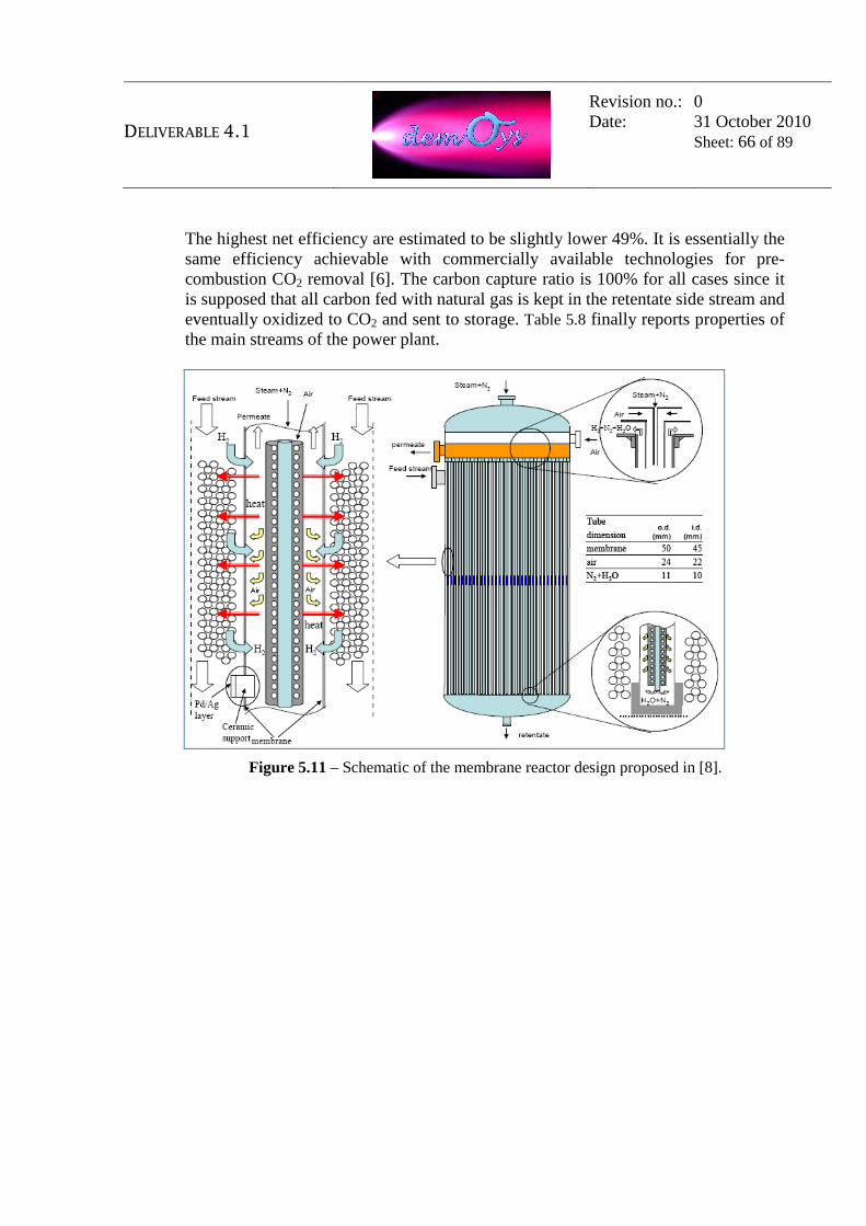
DELIVERABLE 4.1
Revision no.: Date:
0 31 October 2010 Sheet: 66 of 89
The highest net efficiency are estimated to be slightly lower 49%. It is essentially the same efficiency achievable with commercially available technologies for pre-combustion CO2 removal [6]. The carbon capture ratio is 100% for all cases since it is supposed that all carbon fed with natural gas is kept in the retentate side stream and eventually oxidized to CO2 and sent to storage. Table 5.8 finally reports properties of the main streams of the power plant.
Figure 5.11 – Schematic of the membrane reactor design proposed in [8].

DELIVERABLE 4.1
Revision no.: Date:
0 31 October 2010 Sheet: 67 of 89
Table 5.7 – Summary of the results obtained in [8].
Table 5.8 – Properties of the streams for case B2 of the plant considered in [8].

DELIVERABLE 4.1
Revision no.: Date:
0 31 October 2010 Sheet: 68 of 89
5.3. ATR integrated with oxygen separation membranes
5.3.1. OTM integrated in conventional ATR As mentioned before, ATR plants are usually fed with high purity oxygen and therefore an Oxygen Transport Membrane (OTM) may be used instead of the cryogenic air separation unit (ASU), to supply oxygen for a conventional, nickel catalyst based Auto-Thermal Reformer (ATR). The conceptual layout of this solution is described in Figure 5.12. Main advantages of integrating an OTM in an ATR based plant can be related to: − the lower energy consumption respect to a conventional ASU; − replacing an OTM to a cryogenic ASU could make ATR technology
convenient for the small scale, where currently the adoption of ASU is not economically justified.
pressurized air
oxygen-depleted airoxygen
sweep gas
burner
catalyst
radiationshield
synthesisgas to hydrogen separation (PSA)
combustionchamber
pre-reformed natural gas + steamOxygen Transport
Membrane Permeator
oxygenpermeated oxygen
Figure 5.12 – Integration of Oxygen Transport Membrane with conventional Auto-Thermal Reformer.

DELIVERABLE 4.1
Revision no.: Date:
0 31 October 2010 Sheet: 69 of 89
5.3.2. OTM integrated in Catalytic Partial Oxidation
Working principles of the catalytic partial oxidation (CPO) are actually the same as the ATR, with the difference that all the reactions occur in heterogeneous phase. Therefore a CPO reactor does not have the typical burner of the ATR technology and the charge (hydrocarbons, oxidizer and optionally steam) is directly sent to the catalytic zone where the following reactions take place in the same time: partial and complete combustion, methane steam reforming, water gas shift. Catalysts used for CPO are usually based on noble metals (Pt, Pd, Rh, Ir) [11] and allow very short contact time (in the range 0.1÷10 ms) which turns out in high space velocity and the possibility to design very compact reactors that is the main advantage sought by developing this technology. In theory a CPO reactor can be used also in combination with a OTM, but main advantages can be achieved by integrating an OTM membrane in a Oxygen separation membrane (CPO) reactor, as shown in Figure 5.13. In this case O2 partial pressure on the permeate side is virtually zero since permeated O2 promptly reacts with the methane / steam charge to produce hydrogen. This greatly enhances O2 permeation allowing to drastically reduce the membrane surface (and consequently its cost). Drawbacks of CPO are essentially related to the elevated cost of the catalysts and the lack of experience in operating commercial medium or large size reactors.
Oxygen Separation Membrane Catalytic Partial Oxidation (CPO) Reactor
catalyst
oxygen
permeated oxygen
oxygen-depleted airpressurized air
pre-reformed Natural Gas + Steam
synthesis gas
Figure 5.13 – Oxygen Separation Membrane (CPO) Reactor.
Technically speaking, in a ATR reactor homogeneous and heterogeneous reactions are carried out in series as the stream proceeds progressively from combustion zone, to a thermal zone where lower reactions occur (i.e. CO oxidation and pyrolysis of higher hydrocarbons), to the following Ni based catalytic zone where the final conversion of hydrocarbons is carried out mainly through steam reforming. In order to sustain the initial combustion a significant flow of oxidizer is therefore required. This flow is actually unavailable in the membrane reactor since oxygen permeates diffusely directly in the reacting stream. In a CPO case, the reactions are actually the

DELIVERABLE 4.1
Revision no.: Date:
0 31 October 2010 Sheet: 70 of 89
same as the ATR, with the difference that all the reactions occur in heterogeneous phase. Therefore, CPO technology does not have the typical burners of the ATR and it can be conveniently applied to a membrane reactor. Catalysts used for CPO are usually based on noble metals (Pt, Pd, Rh, Ir) which ensure that complete combustion and methane steam reforming take place simultaneously with the resulting advantage that temperature profile does not present sharp variations.

DELIVERABLE 4.1
Revision no.: Date:
0 31 October 2010 Sheet: 71 of 89
5.4. ATR integrated with oxygen and hydrogen separation membranes
5.4.1. Single component oxygen/hydrogen separation membrane-reformer One more possibility to integrate H2 and O2 separation membranes in an hydrogen (and optionally electricity) production plant is described in a proposal from Praxair [14]. The concept proposed by Praxair is the integration of both HTM and OTM into a single unit: oxygen is separated from pressurized air and permeates through an OTM in a compartment where a proper catalyst favors reaction with methane and steam to generate hydrogen that at the same time is separated by an HTM, as illustrated in Figure 5.14. This arrangement on one side favors O2 permeation since O2 promptly reacts on the OTM permeate side (and therefore O2 partial pressure is virtually zero) while on the other side promotes reforming reactions by H2 extraction. The gross H2 production efficiency reported in [14] is 75.8% of the HHV natural gas fed into the system. Nevertheless the reactor design comes out extremely complicate since two different membranes (with different surface area and related feed/permeate streams) should be packed in a single reactor.
Figure 5.14 – Integrated O2/H2 separation membrane in a single unit proposed in [14].
To overcome this hurdle, OTM and HTM can be split over different components, losing some of the advantages of the single step reactor, but significantly gaining in feasibility. Two different arrangements can be considered and discussed in the following two sections.

DELIVERABLE 4.1
Revision no.: Date:
0 31 October 2010 Sheet: 72 of 89
5.4.2. Two components oxygen/hydrogen separation membrane-reformer
In the configuration described in Figure 5.15, oxygen is first separated in a OTM and then cooled, compressed and addressed to HTM reactor along with a charge composed of pre-reformed natural gas and steam. Conceptually this option combines in a single process the solutions described in section 5.3.1 and 5.2.1, and the respective advantages are therefore expected.
pressurized air
oxygen
oxygen-depleted air
sweep gas
hydrogen
oxygen
permeated hydrogen
catalyst
pre-reformed natural gas + steam
sweep gas
carbon dioxide-rich gas
Hydrogen Separation Membrane Reformer
oxygenpermeated oxygen
Oxygen Transport Membrane Permeator
Figure 5.15 – OTM with Hydrogen Separation Membrane Autothermal Reformer.
5.4.3. Two components oxygen/hydrogen separation membrane-CPO reactor
The configuration shown in Figure 5.16 implements solutions described in chapter 5.3.2 and 5.2.1. Syngas exiting the permeate side of oxygen separation membrane CPO reactor is addressed to the feed side of a hydrogen separation membrane reformer. In this case O2 and H2 separation is carried out in sequence in two membrane reactors (rather than in parallel in a single component) preventing to attain all the advantages of the solution proposed by Praxair. In particular in the second reactor, H2 removal promotes endothermic reforming reactions that should be supported by an external heat supply or a temperature decay, while, in the single step reactor, combustion reactions afforded by oxygen permeation can provide all the required heat.
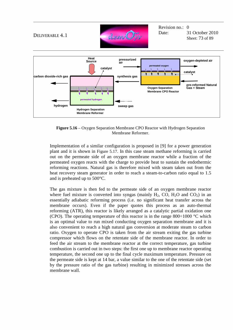
DELIVERABLE 4.1
Revision no.: Date:
0 31 October 2010 Sheet: 73 of 89
Oxygen Separation Membrane CPO Reactor
catalyst
oxygen
permeated oxygen
oxygen-depleted airpressurized air
pre-reformed Natural Gas + Steam
synthesis gas
oxygen
permeated hydrogen
sweep gas hydrogen
carbon dioxide-rich gas
catalyst
Hydrogen Separation Membrane Reformer
Heat Source
Figure 5.16 – Oxygen Separation Membrane CPO Reactor with Hydrogen Separation Membrane Reformer.
Implementation of a similar configuration is proposed in [9] for a power generation plant and it is shown in Figure 5.17. In this case steam methane reforming is carried out on the permeate side of an oxygen membrane reactor while a fraction of the permeated oxygen reacts with the charge to provide heat to sustain the endothermic reforming reactions. Natural gas is therefore mixed with steam taken out from the heat recovery steam generator in order to reach a steam-to-carbon ratio equal to 1.5 and is preheated up to 500°C. The gas mixture is then fed to the permeate side of an oxygen membrane reactor where fuel mixture is converted into syngas (mainly H2, CO, H2O and CO2) in an essentially adiabatic reforming process (i.e. no significant heat transfer across the membrane occurs). Even if the paper quotes this process as an auto-thermal reforming (ATR), this reactor is likely arranged as a catalytic partial oxidation one (CPO). The operating temperature of this reactor is in the range 800÷1000 °C which is an optimal value to run mixed conducting oxygen separation membrane and it is also convenient to reach a high natural gas conversion at moderate steam to carbon ratio. Oxygen to operate CPO is taken from the air stream exiting the gas turbine compressor which flows on the retentate side of the membrane reactor. In order to feed the air stream to the membrane reactor at the correct temperature, gas turbine combustion is carried out in two steps: the first one up to membrane reactor operating temperature, the second one up to the final cycle maximum temperature. Pressure on the permeate side is kept at 14 bar, a value similar to the one of the retentate side (set by the pressure ratio of the gas turbine) resulting in minimized stresses across the membrane wall.

DELIVERABLE 4.1
Revision no.: Date:
0 31 October 2010 Sheet: 74 of 89
Figure 5.17 – Process flow diagram of the power plant proposed in [9].
The syngas exiting the oxygen separation membrane reactor is then cooled and fed to a two steps H2 separation membrane reactor, where water gas shift reaction takes place on the retentate side at two different temperature level (350 °C and 250°C, actually a temperature range suitable for microporous membranes but much lower than the one useful for operation of mixed conducting membranes investigated in DEMOYS). Hydrogen is recovered on the permeate side by means of a steam sweep stream at 2 bar. Stream exiting the WGS membrane reactor is then compressed to 17.5 bar (not shown in Figure 5.17) and sent to the combustor. Thanks to H2 removal, WGS proceeds to almost complete CO conversion so that the stream at the retentate side outlet is almost entirely composed of H2O and CO2 and the system reaches a Hydrogen Separation Factor close to 100%. After water condensation and separation, CO2 can be compressed and sent to storage. The detailed thermal balance and composition of the streams at the membrane reactor limits cannot be deduced from the paper. Anyway, the paper quotes an overall electrical efficiency of 48.1% for the plant just described and claims that a higher efficiency (52.9%) can be achieved by operating the reforming at increased pressure (about 100 bar) so that H2 can be recovered at higher pressure in the following membrane WGS reactor and sent to the gas turbine combustor without any further compression. This performance must be compared to the one of state-of-the-art Natural Gas Combined Cycles, which currently are in the range 56-58%.

DELIVERABLE 4.1
Revision no.: Date:
0 31 October 2010 Sheet: 75 of 89
5.5. References
1. Griffin T., Sundkvist S.G., Asen K, Bruun T.: “Advanced zero emissions gas turbine
power plant”; J Eng Gas Turb Power, 127, 81-85; 2005.
2. Kvamsdal H.M., Jordal K., Bolland O.: “A quantitative comparison of gas turbine cycles with CO2 capture”; Energy, 32, 10-24; 2007.
3. Colombo K.E., Bolland O.: “Dynamic simulation of an Oxygen Mixed Conducting Membrane-based gas turbine power cycle for CO2 capture”; Energy Procedia, 1, 431-438; 2009.
4. Sundkvist S.G., Griffin T., Thourshaug N.P.: “AZEP – Development of an integrated air sepatation membrane gas turbine”; Second Nordic Minisymposium on Carbon Dioxide Capture and Storage, Göteborg, 2001. http://www.entek.chalmers.se/~anly/symp/01sundkvist.pdf
5. Aasen K., Vigeland B., Noeby T., Larring Y. Mejdell T.: “Development of a hydrogen membrane reformer based CO2 emission free gas fired power plant”; Proceeding of GHGT-7; 2004.
http://uregina.ca/ghgt7/PDF/papers/peer/136.pdf.
6. Romano M.C., Chiesa P., Lozza G.: “Pre-combustion CO2 capture from natural gas power plants, with ATR and MDEA processes”; Int J Greenh Gas Con; Article in press, corrected proof, available on line.
7. Jordal K., Bredsen R., Kvamsdal H.M., Bolland O.: “Integration of H2-separating membrane technology in gas turbine processes for CO2 capture”, J. of Energy, 29,1269-1278; 2004.
8. Manzolini G., Djikstra J.W., Macchi E., Jansen D.: “Technical economic evaluation of a system for electricity production with CO2 capture using a membrane reformer with permeate side combustion”, Proceedings ASME Turbo Expo 2006, GT2006-90353, Barcelona, Spain, May 2006.
9. Kaggerud K. Gjerset M., Mejdell T., Kumakiri I., Bolland O., Bredsen R.: “Power production with CO2 management – integration of high temperature CO2 selective membranes in power cycles”, Proceeding of GHGT-7; 2004.
10. Aasberg-Petersen K., Bak Hansen J.-H., Christensen T.S., Dybkjaer I., Seier Christensen P., Stub Nielsen C., Winter Madsen S.E.L., Rostrup-Nielsen J.R.: "Technologies for large-scale gas conversion", Applied Catalysis A: General, Vol. 221, pp 379-387, 2001.
11. Grunwaldt J.-D., Basini L., Clausen B.S.:"In Situ EXAFS Study of Rh/Al2O3 Catalysts for Catalytic Partial Oxidation of Methane", Journal of Catalysis, vol. 200, pp. 321-329, 2001, doi: 10.1006/jcat.2001.3211
12. Kurokawa H., Shirasaky Y., Yasuda I.: “ Energy-Efficient Distributed Carbon Capture in Hydrogen Production from Natural Gas”, proceeding of Greenhouse Gas Control Technologies 10, Amsterdam 2010.
DELIVERABLE 4.1
Revision no.: Date:
0 31 October 2010 Sheet: 76 of 89
13. Shirasaki Y., Tsuneki T., Ota Y., Yasuda I. Tachibana S., Nakajima H., Kobayashi K.:
“Development of membrane reformer system for highly efficient hydrogen production from natural gas”, International Journal of Hydrogen Energy, vol. 34 (2009), pp. 4482 – 4487.
14. Shan M.-M., Drnevich R.-F., BAlachandran S., Dorris S.-E., Lee T.-H.: “Technoeconomic Feasibility if Hydrogen Production by Integrated Ceramic Membrane System”, PROCEEDINGS OF THE 2001 doe Hydrogen Program Review, NREL/CP-570-30535.

DELIVERABLE 4.1
Revision no.: Date:
0 31 October 2010 Sheet: 77 of 89
6. Selected plant configurations As stated in the introduction, WP4 has the main objective of assessing the integration of membranes in power generation and hydrogen production plants at commercial scale. Therefore, a preliminary selection of plant configurations is required in order to define the potential interest for future applications of hydrogen and oxygen separation membranes. Scope of this section is to preliminarily select the most convenient plant schemes for these applications, starting from plant configurations found in the literature and shown in the previous sections 4 and 5. This will allow also defining the membrane operating conditions that will be used for the further development in the work package number 2 (WP2). Further development in WP4 will lead to an optimisation of the configurations presented in this section. Therefore, these novel plant alternatives shall be deemed as preliminary only. With reference to the alternatives listed in Table 3.1, section 6.1 and 6.2 show the preliminarily selected plant schemes, respectively for coal and natural gas-based plants.
6.1. Coal-based plants
6.1.1. Integrated Gasification Combined Cycle (IGCC) IGCC alternative 1
Plant type Output O2 Membranes H2 Membranes
C O A L
IGCC Power (H2)
Provide O2 to the gasifier
-
As shown in section 4.1, the natural application of Oxygen Transport Membranes in Integrated Gasification Combined Cycle (IGCC) plants is in the oxygen production unit, as a substitute of the commonly used cryogenic distillation (ASU). In fact, the scheme proposed by Air Products [Stein, 2009] has the advantage of not altering the conventional plant configuration of an IGCC with cryogenic ASU, also allowing the possible retrofit of existing plants. Several additional advantages may

DELIVERABLE 4.1
Revision no.: Date:
0 31 October 2010 Sheet: 78 of 89
originate from this application, like low footprint requirement, as well as lower investment cost and power demands. From these considerations, the preliminary selected plant configuration for the application of OTM in IGCC plants is that proposed by Stein and reported in Figure 6.1.
Acid Gas
StripperAbsorber
GasificationIsland
Combined Cycle
HRSGGas Turbine
SteamCycle
Coal
Air
Stack
AGR
Oxygen
Air
Shift Reactor
Decarbonized Fuel
Raw Syngas
CO2
CO2 Compression
Syngas Cooling
O2 O2 O2 O2
Decarbonized Fuel
Sweep Gas(steam)
Recuperator BoostCompressor
OTM
OxygenCompressor
Oxygen PlantWater
PSAHydrogen
PSAoff-gas
Oxygen depleted air
Water
Figure 6.1 – Coal Integrated Gasification Combined Cycle integrated with OTM.

DELIVERABLE 4.1
Revision no.: Date:
0 31 October 2010 Sheet: 79 of 89
IGCC alternative 2
Plant type Output O2 Membranes H2 Membranes
C O A L
IGCC Power (H2)
Provide O2 to the gasifier
Separate H2 from syngas
As discussed in section 4.1, the hydrogen separation membranes that are object of the DEMOYS project are not suitable for this application. Actually, the syngas stream from the gasifier still contains solids and potential contaminants as heavy metals and sulfur and this prevents placing a membrane reactor before syngas cleanup carried out at low temperature (below 250 °C). Since mixed conducting membranes operate in the temperature range (800÷1000°C), syngas should be re-heated to that temperature leading to inefficient and expansive plant configurations. Therefore, this alternative 2 is no longer considered in the DEMOYS project.
6.1.2. Oxy-fired plants
Plant type Output O2 Membranes H2 Membranes
C O A L
Oxy-fuel Boiler Power Provide O2 to the
gasifier -
As shown in section 4.2, oxygen transport membranes may be applied to coal-based and oxy-fired power plants. This can be made in Externally Fired Combined Cycles (EFCC) and in coal boilers, either fixed (USC) or fluidised (FBC) bed types [Romano 2005]. However, in the schemes proposed by Romano, the EFCC cycle includes high temperature ceramic heat exchangers (CHX), which represent the major technological hurdle of the plant. In addition, this plant scheme adopts gas turbines that are technically feasible but are not part of the current fleet of commercially available machines. Therefore, the EFCC plant is not considered in the DEMOYS project.

DELIVERABLE 4.1
Revision no.: Date:
0 31 October 2010 Sheet: 80 of 89
On the other hand, CHX are not included in the FBC boiler-based scheme, thus resulting in a less challenging configuration. In addition, the not-invasive integration of the OTM in this plant-type increases the overall plant expected reliability and the possibility for an easier near-term plant realization. From the considerations made in this section, the preliminary selected plant configuration for the application of OTM in Oxy-fired plants is derived from that proposed by Romano and reported in Figure 6.2.
Boiler
Steam Cycle
Power Island
Coal
Oxygen+
Exhaust
Auto-RefrigeratedCO2 Separation
Inertsto Stack
Direct Contact Cooler
CO2
CO2 Compression
FGT
O2 O2 O2 O2
OTM
Turbocharger
Air
HRSG
Stack
MHXOxygen depleted air
Boiler exhaust
CO2 HRSG
Steamto Steam Cycle
Steamto Steam Cycle
Blower
Figure 6.2 – Coal fluidized bed oxy-combustion boiler plant integrated with OTM.

DELIVERABLE 4.1
Revision no.: Date:
0 31 October 2010 Sheet: 81 of 89
6.2. Natural gas-based plants
6.2.1. Oxyfuel NGCC plants
Plant type Output O2 Membranes H2 Membranes
N G
Oxy-fuel NGCC Power Provide O2 to the NG combustion
-
As already explained in section 5.1, the following options have been proposed for the architecture of the MCM reactor, requiring different working conditions for the OTM: • Separate component configuration. • Semi-separate component configuration. • Single component configuration. In general, the separate component configuration leads to a less complicated scheme and to a more operable plant. It is also expected that a lower degree of integration increases the reliability and availability of the plant, also allowing the possible use of equipment, such as heat exchangers and rotating machineries, that are already commercially available, thus not adding further novelties to the application of OTM in these plant types. Similarly to EFCC quoted in par. 6.1.2, the main drawback of these configurations is they are external combustion cycles because compressed air is taken to the turbine inlet temperature by external heat transfer directly in the membrane combustor (single component configuration) or in a ceramic heat exchanger (separate and semi-separate component configuration). This poses additional feasibility issues and for this reason, the implementation of OTM in oxy-fuel combined cycle is not considered in the DEMOYS project.

DELIVERABLE 4.1
Revision no.: Date:
0 31 October 2010 Sheet: 82 of 89
6.2.2. Steam methane reforming plants (SMR)
Plant type Output O2 Membranes H2 Membranes
N G
SMR H2
(Power) -
H2 separation membrane-reformer
As reported in literature and shown in section 5.2, the methane steam reforming can take place in different reactor arrangements, which include membranes for H2 separation and heat exchange. A difficult point of this design is to reach temperature around 700°C for the feed stream entering the membrane reformer. It is also noted that these processes use a membrane-type catalytic reactor, which maybe considered as a technological barrier or challenge, also leading to a potential high investment cost requirement. However, the use of these reactors may lead to processes with high-performances and for this reason they will be further investigated in this project. The configurations presented in section 5.2 have in common the following same basic-concepts: • Before entering the reactor, methane is pre-heated and mixed with steam at
medium pressure; • Thermal energy of the retentate, which is mainly composed by CO2 and H2O, is
recovered after the membrane reformer; • Hydrogen partial pressure is decreased by the sweep stream (if any) that can be
air, oxygen depleted air, steam or a combination of the above; • Heat for the methane reforming endothermic reaction is provided by the
combustion of part of the permeated hydrogen; • In case of power production, permeated hydrogen is delivered to a gas turbine. However, the configurations 2, 3 and 4 present unconventional reactor arrangements that lead to novel configurations with a high-level of uncertainty. Therefore, these plant schemes are not considered at this stage of the project, whilst it is recommended to further investigate these configurations after the final development of the membranes. On the other hand, configuration 1 shows the simplest membrane reactor design, which may find application in the DEMOYS project. Therefore, the preliminary selected plant configuration for the application of hydrogen membranes in NG steam reforming plants is derived from that proposed by Kurokawa et al. and reported in

DELIVERABLE 4.1
Revision no.: Date:
0 31 October 2010 Sheet: 83 of 89
Figure 6.3. In case of power production, hydrogen may eventually be used as main fuel in a combustion turbine (not considered in the selected application). Natural Gas
Pre-Reformer
MP Steam
Hydrogen
H2
H2
H2
H2
H2 SeparationMembrane Reformer
Auto-RefrigeratedCO2 Separation
Inertsto Stack
CO2
CO2 Compression
CO2 HRSG
Steamto Steam Cycle
WaterCondensation
Figure 6.3 – Steam Methane Reforming based on H2 separation membrane-reactor.

DELIVERABLE 4.1
Revision no.: Date:
0 31 October 2010 Sheet: 84 of 89
6.2.3. Auto-thermal reforming plants (ATR)
Alternative 1: ATR+OTM
Plant type Output O2 Membranes H2 Membranes
N G
ATR H2
(Power) Provide O2 to the reforming reactor
-
As discussed in 5.3.1, the typical cryogenic ASU can be replaced by an oxygen plant based on OTM, leading to a possible lower investment cost and electrical consumption. Therefore, the preliminary selected scheme has many similarities with the IGCC plant, as shown in Figure 6.4. In case of power production, hydrogen may eventually be used as main fuel in a combustion turbine (not considered in the selected application).
Syngas Cooling
Natural Gas
Air
Shift Reactor
Raw Syngas
Pre-Reformer
Auto-ThermalReformer
MP Steam
StripperAbsorber
AGR
CO2
CO2 Compression
PSAHydrogen
PSAoff-gas
O2 O2 O2 O2
Sweep Gas(steam)
Recuperator
OTMOxygen
Compressor Oxygen PlantWater
Decarbonized Fuel
Oxygen
HRSG
Steamto Steam Cycle
Stack
Oxygen depleted airTurbocharger
Decarbonized Fuel
Figure 6.4 – Natural gas Auto-thermal Reforming integrated with OTM.

DELIVERABLE 4.1
Revision no.: Date:
0 31 October 2010 Sheet: 85 of 89
Alternative 2: ATR+OTM+HTM
Plant type Output O2 Membranes H2 Membranes
N G
ATR H2
(Power) Provide O2 to the reforming reactor
H2 separation membrane-reformer
The implementation of both hydrogen and oxygen separation membranes in an ATR plant was discussed in section 5.4.2. ASU is substituted by an oxygen plant based on OTM, while the methane is completely converted in the hydrogen separation membrane-reformer. This reactor is conceptually similar to the one selected in 6.2.2, with the main difference that the reaction heat is not provided by external burners (SMR) but by combustion inside the reactor (ATR). The preliminary selected process scheme is shown in Figure 6.5. In case of power production, hydrogen may eventually be used as main fuel in a combustion turbine (not considered in the selected application).
Natural Gas
Pre-Reformer
MP Steam
Hydrogen
Oxygen
H2 H2 H2 H2
H2 SeparationMembrane Reformer
Auto-RefrigeratedCO2 Separation
Inertsto Stack
CO2CO2 Compression
CO2 HRSG
Steamto Steam Cycle
WaterCondensation
Air
O2 O2 O2 O2
Sweep Gas(steam)
Recuperator
OTM
Oxygen Plant
Hydrogen
HRSG
Steamto Steam Cycle
StackOxygen depleted air
Turbocharger
OxygenCompressor
Water
Figure 6.5 – Natural gas Auto-thermal Reforming with H2 Separation Membrane Reformer
and integrated with OTM.
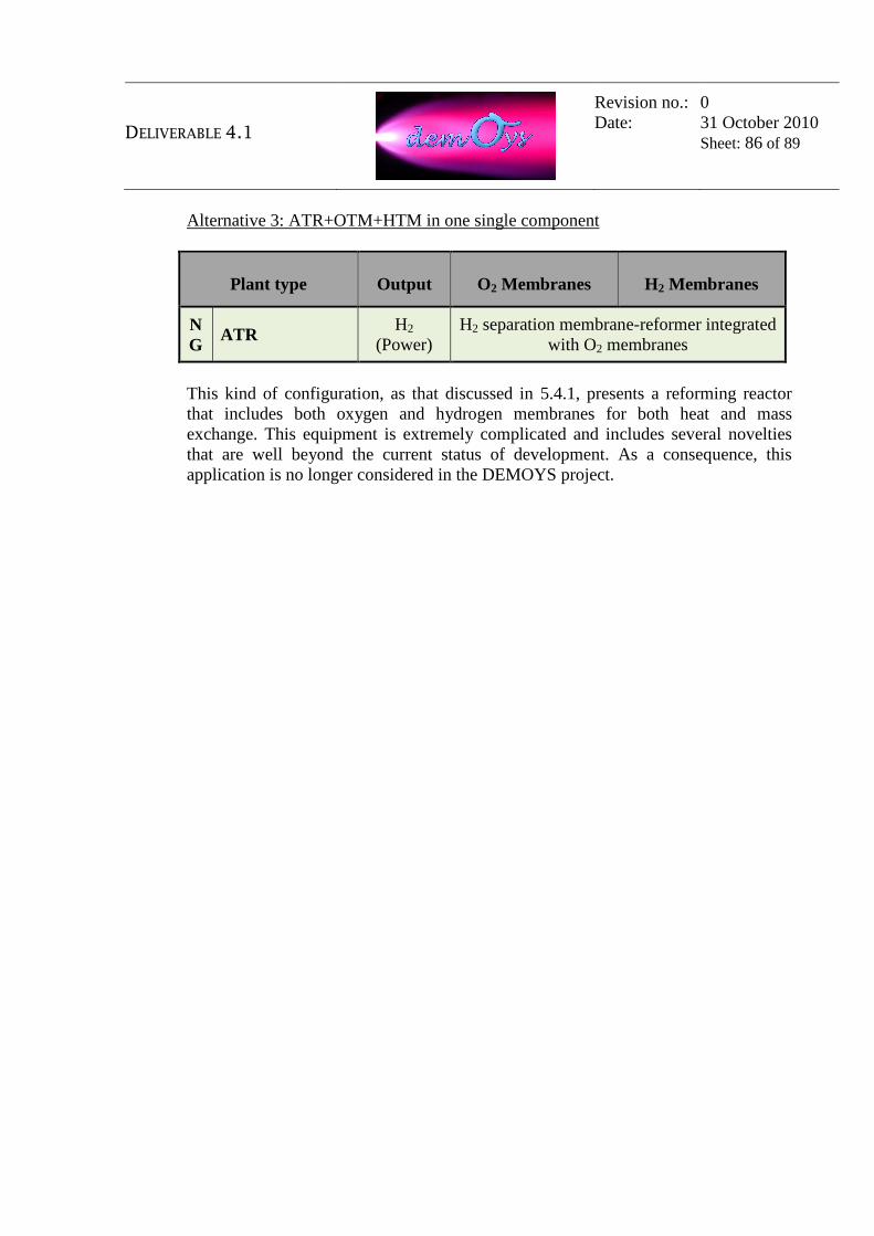
DELIVERABLE 4.1
Revision no.: Date:
0 31 October 2010 Sheet: 86 of 89
Alternative 3: ATR+OTM+HTM in one single component
Plant type Output O2 Membranes H2 Membranes
N G
ATR H2
(Power) H2 separation membrane-reformer integrated
with O2 membranes
This kind of configuration, as that discussed in 5.4.1, presents a reforming reactor that includes both oxygen and hydrogen membranes for both heat and mass exchange. This equipment is extremely complicated and includes several novelties that are well beyond the current status of development. As a consequence, this application is no longer considered in the DEMOYS project.

DELIVERABLE 4.1
Revision no.: Date:
0 31 October 2010 Sheet: 87 of 89
7. Membranes operating conditions
For each plant type preliminarily selected for the DEMOYS project (section 6), the following sections summarize the expected membrane operating conditions to be used for the membrane development (WP2) and the preliminary evaluation of CO2 capture cost (WP6). Figures shown in the next tables are based on the assumption that the required temperature operating range of the membranes is between 800° and 1000°C. It is noted that lower operating temperature range, to be advised by membranes developers, would generally lead to a more conventional plant design.
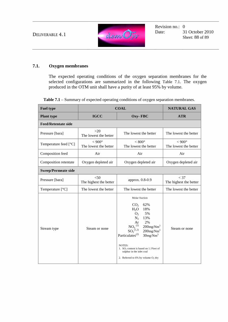
DELIVERABLE 4.1
Revision no.: Date:
0 31 October 2010 Sheet: 88 of 89
7.1. Oxygen membranes The expected operating conditions of the oxygen separation membranes for the selected configurations are summarized in the following Table 7.1. The oxygen produced in the OTM unit shall have a purity of at least 95% by volume.
Table 7.1 – Summary of expected operating conditions of oxygen separation membranes.
Fuel type COAL NATURAL GAS
Plant type IGCC Oxy- FBC ATR
Feed/Retentate side
Pressure [bara] >20
The lowest the better The lowest the better The lowest the better
Temperature feed [°C] < 900°
The lowest the better < 800°
The lowest the better < 900°
The lowest the better
Composition feed Air Air Air
Composition retentate Oxygen depleted air Oxygen depleted air Oxygen depleted air
Sweep/Permeate side
Pressure [bara] <50
The highest the better approx. 0.8-0.9
< 37 The highest the better
Temperature [°C] The lowest the better The lowest the better The lowest the better
Stream type Steam or none
Molar fraction
CO2 62% H2O 18%
O2 5% N2 13% Ar 2%
NOx (2) 200mg/Nm3
SO2(1,2) 200mg/Nm3
Particulates(2) 30mg/Nm3
NOTES: 1. SO2 content is based on 1.1%wt of
sulphur in the inlet coal 2. Referred to 6% by volume O2 dry
Steam or none

DELIVERABLE 4.1
Revision no.: Date:
0 31 October 2010 Sheet: 89 of 89
7.2. Hydrogen membranes The expected operating conditions of the hydrogen separation membranes for the selected configuration are summarized in the following table. The hydrogen at membrane-reactor outlet is expected to have a purity of 99.9% by volume. It is also noted that the membranes’ feed side is in contact with the methane reforming catalyst (usually based on noble metals such as Pt, Pd, Rh, Ir).
Table 7.2 – Summary of expected operating conditions of hydrogen separation membranes.
Fuel type NATURAL GAS
Plant type SMR ATR
Feed/Retentate side
Pressure [bara] 25 25
Temperature feed [°C] The lowest the better The lowest the better
Composition feed
Molar fraction
H2 6% CO 1%
CO2 4% CH4 24% H2O 64%
N2 1%
Molar fraction
H2 7% CO 0%
CO2 2% CH4 23% H2O 49%
N2 2% O2 17%
Composition retentate
By membrane developer, depending on membrane-reactor
performance (mainly CO2 and H2O)
By membrane developer, depending on membrane-reactor
performance (mainly CO2 and H2O)
Sweep/Permeate side
Pressure [bara] The highest the better The highest the better
Temperature permeate [°C] The lowest the better The lowest the better
Stream type None None
Composition permeate 99.9%vol H2 99.9%vol H2