preliminary contents instruction manual sw 2.0_en.pdf · cv #8 = “4” changing 21mtc type c to...
TRANSCRIPT

Sound Decoder MS450P22 for Roco BR 85 Page 1
Preliminary INSTRUCTION MANUAL
Sound decoders MS450P22 f *) “mfx” is a registered trademark of Fa. Gebr. Märklinf & Cie GmbH.
Contents
1 Overview .................................................................................................... 2 2 Technical Data, Notes, mfx-operation ....................................................... 3 3 CVs in DCC operation ............................................................................... 6
3.1 Basic Configuration ................................................................................................................... 6 3.2 Decoder-ID, Load-Code ............................................................................................................ 6 3.3 ManufacturerID, SW version ..................................................................................................... 6 3.4 The vehicle address(es) in DCC mode ..................................................................................... 7 3.5 Analog operation ....................................................................................................................... 8 3.6 Motorregulation ......................................................................................................................... 8 3.7 Acceleration and deceleration momentum: ............................................................................ 11 3.8 Special Operating Mode“ ........................................................................................................ 12 3.9 The ZIMO “signal controlled speed influence” (HLU)Signal contr. speed influence” (HLU) .. 12 3.10 Stop in front of a red signal and driving slowly by asymmetrical DCC-signal stops (Lenz ABC) 12 DC Brake Sections, “Märklin brake mode”DC Brake Sections, “Märklin mode ................................ 12 3.11 Distance controlled stopping - constant braking distance ...................................................... 12 3.12 Shunting, halfspeed, MAN functionsShunting, halfspeed, MAN functions: ............................ 12 3.13 The NMRA-DCC function mapping ......................................................................................... 13 3.14 The ZIMO extended function mapping ................................................................................... 13 3.15 “Unilateral Light Suppression”................................................................................................. 13 3.16 The “Swiss Mapping” .............................................................................................................. 14 3.17 ZIMO “Input Mapping” ............................................................................................................. 17 3.18 Dimming, Low beam and Direction Bits .................................................................................. 17 3.19 Flasher Effect .......................................................................................................................... 18 3.20 F1 Pulse Chain ........................................................................................................................ 18 3.21 Special Effects for Function outputs ....................................................................................... 18 3.22 Configuration of Smoke Generators ....................................................................................... 19 3.23 Configuration of Electric Uncouplers ...................................................................................... 19 3.24 SUSI-Interface and Logic-Level Outputs, Reed-Inputs .......................................................... 19 3.25 Servo Configuration ................................................................................................................ 19 3.26 SOUND: Basic settings independent of powertrain ................................................................ 20 3.27 SOUND: Steam engine sound basic configuration ........................................................... 22 3.28 SOUND: Steam engine Load and acceleration dependency ......................................... 23
Editions
First version for first delivery, SW version 1.00 --- 2018 04 17
2018 07 20 2018 08 23
SW-Version 2.00 --- 2019 01 08

Page 2 Sound Decoder MS450P22 for Roco BR 85
1 Overview
30 x 15 x 4mm SOUND - 1.2 A - 9 Fu-Outputs - 2 Servos - SUSI - DCC, MM, mfx, DC, AC
MS450P22
HO-Sound-Decoder with 9 function outputs, 3 Watt audio on 4 Ohm speaker (or 2 x 8 Ohm), with energy storage circuitry, PluX-22 interface
TYPICAL APPLICATION: HO, O and similar gauges.

Sound Decoder MS450P22 for Roco BR 85 Page 3
2 Technical Data, Notes, mfx-operation
Allowable track voltage .............................................................................................................................. min. 10 V MS450.. AC analog ............................................................................................................ max. pulse... 35 V
max. continuous motor current: MS450 .................................................................................................................................. 1.2 A
Peak motor current MS450 for about 20 sec ......................................................................................................... 2.5 A
Maximum total function output, continuous MS450 ................................................................................................................................... 0.8 A
Maximum continuous total current (motor and functions) ................ = maximum continuous motor current
operating temperature ........................................................................................................ - 20 to 100 °C
Sound sample memory .................................................................. 128 Mbit (= 360 sec at 16 bit / 22kHz) Number of independent sound channels .............................................................................................. 16 Sound amplifier output (Sinus) ....................................................................................................... 3 Watt Speaker impedance ............................................................................................................... min. 4 Ohm
Dimensions (L x W x H) MS450 ................................................................................................................... 30 x 15 x 4 mm
*) The short circuit protection is carried out for the total current of all function outputs.
The decoder type can be read out in CVs #250-252:
CV#250=6, CV#251=4, CV#252=50 = MS450
Software Update:
You need a device that is able to update: ZIMO MXULF/A (Decoder update-and-sound-loading-device), ZIMO central command station MX10 or Roco digital command station Z21. The new SW version is downloaded from www.zimo.at, loaded into a flash drive or sent to the updating device via USB-connection to a computer and ZSP.
This is also how a sound project is loaded into a ZIMO decoder.
Overload and Thermal Protection:
The motor and function outputs of ZIMO decoders are designed with lots of reserve capacities and are additionally protected against excessive current draw and short circuits. Cut-outs are encoun-tered if the decoder is overloaded.
Even tough the decoder is well protected, it is not indestructible. Please pay attention to the following:
Wrong decoder contact: if, for example, the motor leads have contact to track power or an overload connection between the motor brushes and rail pick-ups, this is not always recognized by the overload protection circuit and could lead to damage of the motor power amplifier or even a total destruction of the decoder.
Unfit or defective motors: e.g. coil or commutator shorts are not always recognized by their high current con-
sumption, because these are often just short current spikes. So, they can lead to decoder damage including dam-age to power amplifiers due to long-term exposure.
The power amplifiers of loco decoders (motor as well as function outputs) are not only at risk of overcurrent but also voltage spikes, which are generated by motors and other inductive consumers. Depending on track voltage, such spikes can reach several hundred volts and are absorbed by special protection circuits inside the decoder.
This is why the running voltage shall not be too high, i.e. not higher than intended by the corresponding vehicle.
ZIMO decoders are equipped with temperature sensors to measure their own operating temperature. Power to the motor will be turned off once that temperature exceeds 100°C. The headlights start flashing rapidly, at about 5 Hz, to make this state visible to the operator. Motor control will resume automatically after a drop in temperature of about 20°C (i.e. to about 80°C), typically in about 30 seconds.
Mapping of the PluX-22 interface of the MS450P22:
Fu-Ausgang FA3
SUSI(Data ) Servo2/ /FA10/IN3 ELKO Plus
M otor rechts M otor links
Schiene rechts Schiene links
Fu-Ausgang FA1 Fu-Ausgang FA2 Fu-Ausgang FA5Fu-Ausgang FA7
Scha lteingang IN1SUSI(Clock) Servo1/ /FA9/IN2M ASSE (= ELKO M inus)Licht vorne L f+ Gem. Pluspol Kein Pin ( Index, FA8)Licht hinten Lr Lautsprecher Lautsprecher Fu-Ausgang FA4Fu-Ausgang FA6
Page 4 Sound Decoder MS450P22 for Roco BR 85
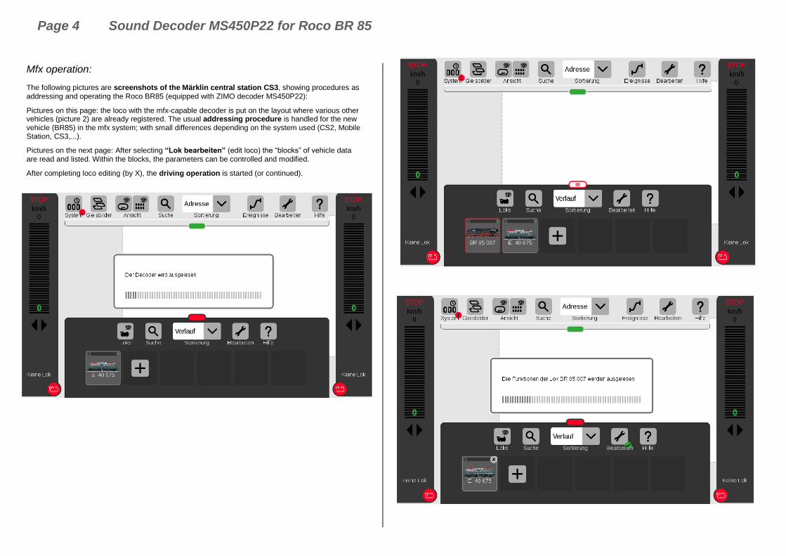
Mfx operation:
The following pictures are screenshots of the Märklin central station CS3, showing procedures as addressing and operating the Roco BR85 (equipped with ZIMO decoder MS450P22):
Pictures on this page: the loco with the mfx-capable decoder is put on the layout where various other vehicles (picture 2) are already registered. The usual addressing procedure is handled for the new vehicle (BR85) in the mfx system; with small differences depending on the system used (CS2, Mobile Station, CS3,...).
Pictures on the next page: After selecting “Lok bearbeiten” (edit loco) the “blocks” of vehicle data are read and listed. Within the blocks, the parameters can be controlled and modified.
After completing loco editing (by X), the driving operation is started (or continued).

Sound Decoder MS450P22 for Roco BR 85 Page 5

Page 6 Sound Decoder MS450P22 for Roco BR 85
3 CVs in DCC operation
3.1 Basic Configuration
CV Denomination Range Default Description
#12 Operating modes 117
Bit 0 - DC analog 0 = disabled 1 = enabled Bit 4 - AC analog 0 = disabled 1 = enabled Bit 5 - MM 0 = disabled 1 = enabled Bit 6 - mfx 0 = disabled 1 = enabled
Value 0 = all modes enabled
#27 Automatic stopping 21
Bit 4 - DC braking section, if polarity is reversed 0 = disabled 1 = enabled
Bit 5 - DC braking section, if polarity is equal to direction of travel 0 = disabled 1 = enabled
#28
RailCom Configuration
planned in SW version 2.00
0 - 3 3
Bit 0 - RailCom Channel 1 (Broadcast) 0 = OFF 1 = ON
Bit 1 - RailCom Channel 2 (Data) 0 = OFF 1 = ON
#29
Basic Configuration 0 - 63
14 =
0000 1110
Bit 3 = 1 (“RailCom”
on)
and
Bits1 & 2 = 1 (28 or 128
speed steps and automat-ic analog op-eration ena-
bled)
Bit 0 - Train direction: 0 = normal, 1 = reversed
Bit 1 - Number of speed steps: 0 = 14, 1 = 28/128 speed steps
Bit 2 - automatic change to analog operation 0 = disabled 1 = enabled
Bit 3 - RailCom („bi-directional communication“) 0 = deactivated 1 = activated SW version 2.00 and later!
Bit 4 - Individual speed table: 0 = off, CVs #2, 5 and 6 are active. 1 = on, according to CVs #67 – 94
Bit 5 - Decoder address: 0 = primary address as per CV #1 1 = ext. address as per CVs #17 & 18
3.2 Decoder-ID, Load-Code
CV Denomination Range Default Description
#250, #251, #252, #253
Decoder-Type
(see chapter 1, Overview)
Read only -
CV #250 = decoder-class (1=function decoder, 2=decoder, 6=sound-decoder)
CV #251 = Hundredths digit of type classification
CV #252 = Tens and ones digit of type classification
CV #253 = hardware revision
3.3 ManufacturerID, SW version
CV Denomination Range Default Description
#8
Manufacturer
ID
and
HARD RESET
with CV #8 = “8”
or CV #8 = 0
Read only
always shows “145”
for ZIMO
ID
Pseudo- programming see explana-
tion to the right-
145
( = ZIMO)
Reading out this CV always result in “145” (”10010001”), the number issued for ZIMO by the NMRA.
This CV is also used for various resetting processes with the help of Pseudo-Programming. Pseudo-Programming means that the entered value is not really stored, but rather used to start a defined action.
CV #8 = “3” changing 21MTC type D to type C CV CV #8 = “4” changing 21MTC type C to type D
CV #8 = “8” HARD RESET (NMRA standard);
all CVs return to the last active CV set or sound pro-ject, or the default values listed in this CV table if no such set was active before.
#7 SW version number
Also see CV #65 Sub-Version number
Read only -
This CV holds the firmware version number currently in the decoder.
CV #7 = number of “main” version CV #65 = Sub-version number
#65
SW- Sub-Version Number
Also see CV #7 for Version number
Read only -
If there are subversions to the SW version in CV #7, it is read out in CV #65. The entire SW version number is thus composed of CVs #7 and #65 (i.e. 28.15).

Sound Decoder MS450P22 for Roco BR 85 Page 7
3.4 The vehicle address(es) in DCC mode
Decoders are usually delivered with default address 3 (CV #1 = 3), for the DCC as well as the MM (Märklin Motorola) format. All aspects of operations are possible with this address but it is recom-mended to change to a different address as soon as possible.
The address space required for DCC exceeds the range of a single CV, up to 10239 in fact. For ad-dresses higher than 127, CVs #17 & #18 are used. Bit 5 in CV #29 is used to select between the short address in CV #1 and the long address in CV’s #17/18.
Most digital systems (with the possible exception of very old or simple products) automatically calcu-late the value for the CVs involved, and also set CV #29 Bit 5 to the proper value when writing the address, so that the user does not have to deal with the necessary coding.
CV Denomination Range Default Description
#1 Locomotive address
DCC: 1 - 127
MM: 1 - 255
3
The “small” (or “short”) vehicle address (DCC, MM)
In case of DCC operation:
Primary address as per CV #1 is only valid, if CV #29 (basic configuration), Bit 5 = 0.
Otherwise, the address per CVs #17 & #18 is valid, i.e. if CV #29, Bit 5 = 1.
#17 & #18
Extended (long) ad-dress
128 -
10239 0
The long (“extended”) DCC address applies to addresses >127.
The loco address per CVs #17 & #18 is valid, if CV #29 (basic configuration), Bit 5 = 1.
#29
Basic configuration
0 - 63
14 =
0000 1110
Bit 5 = 0 (“small”
address)
Bit 0 - Train direction: 0 = normal, 1 = reversed
Bit 1 - Number of speed steps: 0 = 14, 1 = 28/128 speed steps
Bit 2 - automatic change to analog operation 0 = disabled 1 = enabled
Bit 3 - RailCom („bidirectional communication“) 0 = deactivated 1 = activated
Bit 4 - Individual speed table: 0 = off, CVs #2, 5 and 6 are active. 1 = on, according to CVs # 67 – 94
Bit 5 - Decoder address: 0 = primary address as per CV #1 1 = “extended” address per CVs #17 & #18
Decoder-controlled consisting (a.k.a. “Advanced consisting”)
The combined operation of two or more locomotives (in consist function) with the same speed can be managed by
- the DCC system (common practice with ZIMO systems, without changing any decoder CVs) or - by programming the following decoder CVs individually, but can also be managed by some DCC systems (often the case with American made systems).
This chapter only covers the decoder-controlled consisting!
CV Denomination Range Default Description
#19
Consist address
planned in SW version 3.00
0,
1 – 127
129 - 255 ( = 1 - 127
with inverted Direc-
tion)
0
Alternate loco address for consist function:
If CV #19 > 0: Speed and direction is governed by this consist address (not the individual address in CV #1 or #17&18); functions are controlled by either consist ad-dress or individual address, see CVs #21 & 22.
Bit 7 = 1: Driving direction of this loco reversed
#20
Extended
consist address
planned in SW version 3.00
0 - 102 0
“Extended” consist address: the value defined in CV #20 is multiplied by 100 and added to the value in CV #19, which then results in the address in consist operation. E.g. CV#20 = 12, CV#19=34 equals addr. 1234; CV#20=100, CV#19=00 equals addr. 10000
#21
Functions F1 - F8
consist functions
planned in SW version 3.00
0 - 255 0
Functions defined here will be controlled by the consist address.
Bit 0 = 0: F1 controlled by individual address = 1: …. by consist address
Bit 1 = 0: F2 controlled by individual address = 1: …. by consist address ………. F3, F4, F5, F6, F7
Bit 7 = 0: F8 controlled by individual address = 1: …. by consist address
#22
Functions
F0 forw. rev. in consist function
planned in SW version 3.00
0 - 255 0
Select whether the headlights are controlled with consist or individual address.
Bit 0 = 0: F0 (forw.) controlled by individual address = 1: …. by consist address
Bit 1 = 0: F0 (rev.) controlled by individual address = 1: …. by consist address
Bit 2 = 0: F9 (forw.) controlled by individual address = 1: …. by consist address
Bit 3 = 0: F10 (forw.) controlled by individual address = 1: …. by consist address
Bit 4 = 0: F11 (forw.) controlled by individual address = 1: …. by consist address
Bit 5 = 0: F12 (forw.) controlled by individual address = 1: …. by consist address Bit 7 = 1: F13 – F27 (all!) ….by consist address
Bit 6 = 1: Auto consist: The system changes automati-cally between individual and consist address, if one of the two addresses has speed 0 and the other has speed >0.

Page 8 Sound Decoder MS450P22 for Roco BR 85
3.5 Analog operation
All ZIMO decoders are capable of operating on conventional layouts with DC power packs, including PWM throttles, in analog DC as well as in analog AC (Märklin transformers with high voltage pulse for direction change).
With the first SW version only AC analog is active, DC-analog is planned in later software versions.
To allow analog operation,
CV #29, Bit 2 = 1 must be set.
This is usually the case by default (CV #29 = 14, which includes Bit 2 = 1), but analog operation may be turned off in many sound projects (sound decoders).
The actual behavior during analog operation, however, is strongly influenced by the locomotive con-troller (power pack). Especially in combination with a weak transformer, it is easily possible that the track voltage collapses when the decoder (motor) starts to draw power which, in the worst case, may lead to intermittent performance.
In the analog operation, it is possible to adjust the acceleration momentum (CV #14, Bit 6) and func-tion outputs (CV #13 & #14).
Note: Actual decoder settings may differ from the default values if a sound project is on the decoder.
CV Denomination Range Default Description
#29
Basic Configuration 0 - 63
14 =
0000 1110
so Bit 2 = 1 Analog
operation
Bit 1 - Number of speed steps: 0 = 14, 1 = 28/128 speed steps
Bit 2 - automatic change to analog operation 0 = disabled 1 = enabled and so on..
#13
#14
Functions F1 - F8
Functions F0 forw. rev.
F9 - F12
in analog operation (= observation mode)
,
and
Acceleration/ Deceleration, control in analog operation
(CV #13)
0 - 255
(CV #14)
0 - 255
(CV #13)
0
(CV #14)
64 so
Bit 6 = 1:
Bit 0 = 0: F1 is OFF in analog mode = 1: …ON in analog mode
Bit 1 = 0: F2 is OFF in analog mode = 1: …ON in analog mode ………. F3, F4, F5, F6, F7
Bit 7 = 0: F8 is OFF in analog mode = 1: …ON in analog mode
Bit 0 = 0: F0 (forw) is OFF in analog mode = 1: …ON in analog mode Bit 1 = 0: F0 (rev) is OFF in analog mode = 1: …ON in analog mode ………. F9, F10, F11
Bit 5 = 0: F12 is OFF in analog mode = 1: …ON in analog mode Bit 6 = 0: Analog operation with acceleration and de-
celeration according to CVs #3 and #4; use-ful for sound
= 1: unregulated DC operation i.e. without acceleration and deceleration according to CV #3 and #4. This is similar to a classical analog operation.
3.6 Motor regulation
The speed table
There are two types of speed curves, which are selected with
CV #29, Bit 4= 0: 3-point characteristic (defined by 3 CVs)
... = 1: 28-step curve (defined by 28 CVs)
3-point speed table: the lowest, highest and medium speed is defined by the Configuration Variables #2 (Vstart), #5 (Vhigh) and #6 (Vmid) (=external speed step defined by slider position). This is a sim-ple way to quickly establish a speed range and its curvature. 28-point speed table (a.k.a. ”free programmable speed table”): with the help of CVs #67 - 94, all 28 external speed steps can be assigned freely to the internal speed steps (0-255). These 28 CVs apply to all speed step modes (14, 28 and 128). If 128 external speed steps are used, the decoder adds the missing intermediate values by interpolation.
0
10
20
30
40
50
60
70
80
90
100
110
120
130
140
150
160
170
180
190
200
210
220
230
240
250
0 1 2 3 4 5 6 7 8 9 10 11 12 13 14 15 16 17 18 19 20 21 22 23 24 25 26 27 28
0 9 18 27 36 45 54 63 72 81 90 99 108 117 1 26
L ineare
Kennlin
ie - V
start=1, Vhigh=
252, Vm
id=
127
Leicht geknickte Kennlinie (Default-Kennlinie)Vmid = 1 (entspricht 85) Vstart = 2 Vhigh = 1 (entspricht 252)
inte
rne
Fah
rstu
fe
externe Fahrstufe
Mitte
CV Denomination Range Default Description
#29 Basic configuration 0 - 63
14 =
0000 1110
so Bit 4 = 0 (3-point
speed table)
Bit 0 - Train direction: 0 = normal, 1 = reversed
Bit 1 - Number of speed steps: 0 = 14, 1 = 28/128
Bit 2 - automatic change to analog operation 0 = disabled 1 = enabled
Bit 4 - Individual speed table: 0 = off, CVs #2, 5 and 6 are active. 1 = on, according to CVs # 67 – 94
Bit 5 - Decoder address: 0 = primary address as per CV #1 1 = ext. address as per CVs #17 & 18
#2 Start Voltage
Vstart 1 - 255 1
Internal speed step (1 … 255)
applied as lowest external speed step (= 1) (applies to 14, 28, or 128 speed step modes)
= 1: lowest possible speed
#5 Top Speed
Vhigh 0 - 255
0, 1
equals 255
Internal speed step (1 … 255)
applied as highest external speed step (that is, speed step 14, 28 or 128 depending on the speed step mode selected in CV #29, Bit 1).
=0 = 1 (same as 255): fastest speed possible
0
10
20
30
40
50
60
70
80
90
100
110
120
130
140
150
160
170
180
190
200
210
220
230
240
250
Begrenzte lineare KennlinieVstart = 10, Vhigh = 165,Vmid = 90
0
10
20
30
40
50
60
70
80
90
100
110
120
130
140
150
160
170
180
190
200
210
220
230
240
250
0
10
20
30
40
50
60
70
80
90
100
110
120
130
140
150
160
170
180
190
200
210
220
230
240
250
Beispiel einer frei program-mierten Geschwindigkeits-kennlinie (entsprechendeEintragungen in den Konfi-gurationsvariablen # 67 - 94)

Sound Decoder MS450P22 for Roco BR 85 Page 9
CV Denomination Range Default Description
#6
Medium speed
Vmid
with 3-point table if CV #29, Bit 4 = 0
1 - 255 1
(= about 1/4 of top speed)
Internal speed step (1 … 255)
for medium external speed step (that is, speed step 7, 14 or 64 depending on the speed step mode selected in CV #29, Bit 1)
”1" = default (Medium speed is set to one fourth of top speed. I.e., if CV #5 = 255 the curve is the same as if CV #6 would be programmed to 64).
The speed curve resulting from CVs #2, 5 and 6 is automatically smoothed out.
#67 .…..
#94
Free (28-point)
speed table
if CV #29, Bit 4 = 1
0 - 255 *)
internal speed steps (each 1-255) for each of the 28 external steps.
Additionally CV #2 and CV #5.
*) The 28-point default curve is also bent in the lower speed range.
The reference voltage for motor regulation
CV #57 specifies the base voltage used for motor regulation. For example: if 14V is selected (CV
value: 140) the decoder tries to send the exact fraction of this voltage, determined by the speed regu-lator position, to the motor, regardless of the voltage level at the track. As a result, the speed remains constant even if the track voltage fluctuates, provided the track voltage (more precisely, the rectified and processed voltage inside the decoder, which is about 2V lower) doesn’t fall below the absolute reference voltage.
The default value “0” in CV #57 selects the “relative reference”, which automatically adjusts the refer-ence voltage to the available track voltage. This setting is only useful if the system can keep the track voltage constant at all times (stabilized track output) and the resistance along the track kept to a mini-mum. All ZIMO systems keep the track voltage stable, even older systems, but not every system from other manufacturers do, especially relatively cheap systems built before 2005. It is not recommended to set CV #57 to “0” with systems that don’t keep track voltage stabilized. Instead set this CV about 2V be-low track voltage (i.e. 140 for 16V).
CV #57 can also be used as an alternative to CV #5 (top speed), which has the advantage that the full resolution of the 255 speed steps remains available.
CV Denomination Range Default Description
#57 Voltage reference 0,
100 - 255 0
Absolute voltage in tenth of a volt applied to the motor at full speed (max. throttle setting). A useful (and well functioning) range is 10 to 24 V (i.e. 100-240), and lower than the expected track voltage.
Example: A system from another manufacturer is set to 22V at idle but drops to 16V under load: A good set-ting would be CV #57 = 140…150.
CV #57 = 0: automatically adjusts to the track voltage (relative reference); only useful with stabilized track voltage.
Tweaking the motor regulation
Simplified version from SW version 2.5
The motor’s performance, especially at crawling speeds (as judder-free as possible), can be fine-tuned with the following CVs:
CV #9 – Motor control frequency and EMF sampling rate
The motor is controlled by pulse width modulation that can take place at either low or high frequency. Low frequency (30 – 159 Hz) is only useful for very few locomotives with very old motors (i.e. AC mo-tors with field coils instead of permanent magnets). High frequency (20 kHz by default, up to 40 kHz as per CV #112) on the other hand is quiet and easy on the motor.
Power to the motor is interrupted periodically (50 – 200 times/sec.), even when operating at high fre-quency, in order to determine the current speed by measuring back-EMF (voltage generated by the motor). The more frequent this interruption takes place (sampling rate), the better; but that also caus-es power loss and increased noise. By default, the sampling frequency varies automatically between 200 Hz at low speed and 50 Hz at maximum speed.
CV #9 allows the adjustment of the sampling frequency (tens digits) as well as the sampling time (ones digits). The default value of 55 represents a medium setting.
CV # 56 – The PID regulation
The motor regulation can be tailored to motor type, vehicle weight and so on, by using different Pro-
portional-Integral-Differential values. In reality, changing the differential value can be omitted.
CV #56 allows the proportional value (tens digit) as well as the integral value (ones digit) to be set in-dividually. The default value of 55 represents a medium setting.
CV Denomination Range Default Description
#9
Motor control period
or frequency
and
EMK sampling rate
55
High fre-quency, medium sampling
rate
01 - 99
High fre-quency
with modi-fied sam-pling rate
255-176
Low fre-quency
55
High fre-quency medium
Sampling rate
Default motor control with high frequency (20/40kHz), medium EMF sampling rate that automatically adjusts between 200 Hz (low speed) and 5 Hz and medium EMF sampling time.
<> 55: Modification of automatic adjustments, each divided in: tens digit for sampling rate and ones digit for sampling time.
Tens digit 1 - 4: Lower sampling rate than default (less noise!)
Tens digit 6 - 9: Higher sampling rate than default (to combat juddering!)
Ones digit 6 - 4: Shorter EMF sampling time (good for coreless motors, less noise, more power)
Ones digit 6 - 9: Longer EMF sampling time (may be needed for round motors or similar).
Typical test values against jerky driving: CV #9 = 55 (default) 83, 85, 87, ... CV #9 = 55 (default) 44, 33, 22, … = 255 - 176: Low frequency (for old motors only!) – PWM according to formula (131+ mantissa*4) *2exp. Bit 0-4 is “mantissa”; Bit 5-7 is “exp”. Motor frequency is the reciprocal of the PWM.
Examples: CV #9 = 255: frequency at 30 Hz, CV #9 = 208: frequency at 80 Hz, CV #9 = 192: frequency at 120 Hz.

Page 10 Sound Decoder MS450P22 for Roco BR 85
#112
Special ZIMO configuration bits
0 - 255
4 = 00000100
Bit 0 = value-dependent (0) load dependent sound table (1), characteristic defined in CVs #137 - #139. Bit 1 = 0: Normal acknowledgement. = 1: High frequency acknowledgement Bit 2 = 0: ZIMO loco number recognition OFF = 1: ZIMO loco number recognition ON Bit 3 = 0: 12-Function Mode = 1: 8-Function Mode
Bit 4 = 0: Pulse chain recognition OFF = 1: Pulse chain recognition (for old LGB)
Bit 5 = 0: motor control with 20 kHz = 1: 40 kHz motor control frequency Bit 6 = 0: normal (also see CV #29) = 1: “Märklin brake section”
#56
P and I value
for
EMK-load balance con-trol
55
medium PID
setting
01 - 199
modified settings
55
= 55: default setting using medium PID parameters.
= 0 - 99: Modified settings for “normal” DC motors. = 100 - 199: Modified settings for coreless motors (Faulhaber, Maxxon etc.)
Tens digit 1 - 4: Lower proportional value than default
Tens digit 6 - 9: Higher proportional value than default
Ones digit 1 - 4: Lower integral than default
Ones digit 6 - 9: Higher integral than default
Typical test values against jerky driving: CV #56 = 55 (default) 33, 77, 73, 71, ..
#147 EMK – sampling time extended range
0 - 255 0
Useful value to start: 20 For Fleischmann motors to avoid stuttering; values too big worsens the regulation. Slowly elevate the value until the stuttering is gone.
Tips on how to find the optimal CV #56 settings:
Start with an initial setting of CV #56 = 11; set the engine at low speed while holding it back with one hand. The motor regulation should compensate for the higher load within half a second. If it takes longer than that, increase the ones digit gradually: CV #56 = 12, 13, 14...
With the locomotive still running at a low speed, increase the tens digit in CV #56. For example: (if the test above resulted in CV #56 = 13) start increasing the tens digit CV #56 = 23, 33 ,43…as soon as juddering is detected, revert back to the previous digit this would be the final setting.
Load Compensation, Compensation Curve and Experimental CVs The goal of load compensation, at least in theory, is to keep the speed constant in all circumstances (only limited by available power). In reality, though, a certain reduction in compensation is quite often preferred.
100% load compensation is useful within the low speed range to successfully prevent engine stalls or run-away under light load. Load compensation should be reduced as speed increases, so that at full speed the motor actually receives full power. Also, a slight grade-dependent speed change is often considered more prototypical.
Locomotives operated in consists should never run at 100% load compensation in any part of the speed range, because it causes the locomotives to fight each other and could even lead to derail-ments.
The overall intensity of load compensation can
be defined with CV #58 from no compensation
(value 0) to full compensation (value 255). Use-ful values range from 100 to 200.
For a more precise or more complete load compensation over the full speed range use CV #10 and CV #113 together with CV #58 to define a 3-point curve.
CV Denomination Range Default Description
#58 BEMF intensity 0 - 255 255
Intensity of back-EMF control at the lowest speed step.
If needed - usually not - an additional BEMF control can be defined by CV #10 and CV #113 - together those three (#58, #10, #113) form a three-point curve for the control.
Example:
# 58 = 0: no back-EMF (like unregulated decoders) # 58 = 150: medium compensation, # 58 = 255: maximum compensation.
#10 Compensation cut-off
This CV is rarely required 0 - 252 0
Assigns an internal speed step where back EMF inten-sity is reduced to the level defined in CV #113. CV #10, #58 and #113 together define a back-EMF curve.
= 0: default curve is valid (as in CV #58).
#113 Compensation cut-off
This CV is rarely required 0 - 255
0
The BEMF intensity is reduced to this value at the speed step defined in CV #10. CV #113 together with CVs #58 and #10 forms a 3-point BEMF curve.
= 0: actual cut-off at speed step in CV #10. Usually CV #10 is also set to 0.
#145
#147
#148
#149
#150
Experimental CVs for test purposes,
to find out whether cer-tain automatic settings have a negative effect on motor regulation. Using these experi-
mental CVs will deacti-vate the automatic set-
tings.
0
0
0
0
0
--- CV #145 = 1: Special setting for Fleischmann motor. --- CV #147 Sampling time --- Useful initial value: 20; Too small a value leads to jerky behavior. Too large a value leads to poor low speed control. 0 = automatic control (CV #147 has no effect)
--- CV #148 D-Value --- Useful initial value: Too small a value leads to poor regulation (regulates too little, too slow, engine judders (rather slowly)); if the value is too high, it over-regulates, loco will tremble.
0
10
20
30
40
50
60
70
80
90
100
110
120
130
140
150
160
170
180
190
200
210
220
230
240
250
0
10
20
30
40
50
60
70
80
90
100
110
120
130
140
150
160
170
180
190
200
210
220
230
240
250
Defa
ult-R
egelu
ngskennlin
ie
Regelungskennlinie
CV # 10 = 126, CV # 113 = 200,
verstärkte Ausreglung im
mittleren Geschwin-
digkeitsbereich.

Sound Decoder MS450P22 for Roco BR 85 Page 11
CV Denomination Range Default Description
CVs #147 – 149 will like-ly be removed again
from the decoder SW at some time.
CV #145 = 10,11,12,13 for C-Sinus mo-
tors see chapter 6
0 = automatic control (CV #148 has no effect)
--- CV #149 P-Value --- 0 = automatic control (CV #149 has no effect) 1 = P-Value is fixed as per CV #56 (tens digit)
--- CV #150 Load compensation at top speed --- Load compensation at top speed normally is always 0. This can be changed with CV #150. Example: CV #58 = 200, CV #10 = 100, CV #113 = 80, CV #150 = 40 -> Result: Regulation at speed step 1 is 200 (of 255, almost 100%), at speed step 100 it is 80 (@1/3
of 255), at speed step 252 (full speed) it is 200
(of 255, almost fully regulated). We kindly ask for your cooperation. Please send us your test results!
The Motor Brake This brake is useful for vehicles without worm gears to prevent them from rolling away on inclines, picking up speed on declines as well as to prevent a heavy train from pushing a standing engine downhill.
CV Denomination Range Default Description
#151 Motor brake 0 - 99 0
= 0: brake not active = 1 - 9: The motor brake is gradually actuated (over a period of 1, 2 … 8 seconds, up to full braking power by shorting both motor power amplifier) if target speed is not reached (not slowing down) after cutting power to the motor (zero PWM to the motor).
The higher the value, the faster and harder the brake is being applied.
= Tens digit 1 - 9: Reduction of the motor regulation if consist-key is active. The values 1 - 9 reduce the con-trol to 10% - 90% of the value set in CV #58.
3.7 Acceleration and deceleration momentum: The basic acceleration and deceleration times (momentum) are set with
CVs #3 and #4 according to the
relevant NMRA standard, which demands a linear progression (the time between speed step chang-es remains constant over the whole speed range). For simple smooth drivability use values 3 or higher but for really slow starts and stops start with a value of 5; values higher than “30” are rarely useful, except in combination with the “braking key”.
Important note regarding acceleration behavior - difference to ZIMO decoders of the MX-series:
The acceleration and deceleration behavior according to CVs #3 & #4, refers to the speed steps that are established by the speed table (including interpolation states), both with 3-point and 28 point-speed table. This means, an expo-nential - not linear - speed table also triggers a corresponding acceleration and deceleration behavior. Usually (also default) such a non-linear speed table is defined.
MX-decoders adjust acceleration and deceleration in 255 equidistant speed steps, regardless of the speed table. Therefore the MX-decoders have special CVs #121 and #122 to change the speed table to an exponential rate, which
is not needed with the MS-decoders.
The sound project in sound decoders always comes with different values in CVs #3 and #4 (as well as many other CVs) than what is listed in the CV charts. Often the sound can only be played back correctly in conjunction with the acceleration times provided by the sound project (or certain minimum values), so the sound project’s default values should therefore not be changed too much.
CV Denomination Range Default Description
#3 Acceleration time 0 - 255 (2)
The value multiplied by 0.9 equals acceleration time in seconds from stop to full speed.
The effective default value for sound decoders is usual-ly not the value given here, but is determined by the loaded sound project.
#4 Deceleration time (de-celeration)
0 - 255 (1)
The value multiplied by 0.9 equals deceleration time in seconds from full speed to a complete stop.
The effective default value for sound decoders is usual-ly not the value given here, but is determined by the loaded sound project.
#23 Acceleration variation 0 - 255 0 For a temporary elevation/decrease (Bit 7 = 0/1) of the acceleration time defined in CV #3.
#24 Deceleration variation 0 - 255 0 For a temporary elevation/decrease (Bit 7 = 0/1) of the deceleration time defined in CV #3.

Page 12 Sound Decoder MS450P22 for Roco BR 85
3.8 Special Operating Mode
Planned in SW-Version 3.0 and later!
3.9 The ZIMO “signal controlled speed influence” (HLU) Planned in SW version “2.5” (= not yet in 2.0, probably an intermittent version before 3.0)
3.10 Stop in front of a red signal and driving slowly by asymmetrical DCC-signal stops (Lenz ABC)
The “asymmetrical DCC signal” is an alternative method for stopping trains at a “red” signal. A simple circuit made up of 4 or 5 commercially available diodes is all that is required.
Usually, the stop section contains 3 to 5 sili-con diodes in series and one diode in paral-lel in the opposite direction is the usual ar-rangement. The different voltage drops across the diodes results in an asymmetry of about 1 to 2V. The direction in which the diodes are mounted determines the polarity of the asymmetry and with it the driving di-rection a signal stop is initiated.
The asymmetrical DCC signal stop mode needs to be activated in the decoder with CV #27. Normally Bit 0 is set, that is CV #27 = 1, which results in the same directional control as decoders from Lenz.
CV Denomination Range Default Description
#27
Position-dependent stopping
(“in front of a red signal”)
or driving slowly
by
“Asymmetrical DCC signal”
(ABC)
planned in SW version 2.00
0, 1, 2, 3 0
Bit 0 = 1: stop, if voltage is higher in the right rail (in driving direction) than in the left. This, i.e. CV #27 = 1 is the USUAL APPLICATION if decoder is correctly wired according to current collector.
Bit 1 = 1: stop, if voltage is higher in the left rail (in driv-ing direction) than in the right.
Traveling in the opposite direction will have no effect. Use the other bit in case the train stops in the wrong di-rection!
Bit 0 and Bit 1 = 1 (CV #27 = 3): stopping independently of direction of travel.
#49, #50
Acceleration, deceleration time
0 - 255 0 See chapter HLU. planned in SW version 2.00
#53
Slow speed
planned in SW version 2.00
0 - 255 70
Internal speed steps for the ABC slow speed
3.11 DC Brake Sections, “Märklin brake mode”
See CV #27 (chapter “basic configuration”)
3.12 Distance controlled stopping - constant braking distance
Planned in SW-Version 3.0 and later!
3.13 Shunting, halfspeed, MAN functions
On the one hand, defining the different Configuration Variables (#3, #4, #23, #24) offers prototypical ac-celeration and deceleration behavior, but is, on the other hand, often obstructive to quick and easy shunting.
This is why the momentum can temporarily be reduced or eliminated altogether with a dedicated function key. Also, during shunting maneuvers it is sometimes helpful to have the speed range of the throttle cut in half.
#155 Selecting a function key
for half speed 0 - 19 0
Defines a function key for half-speed activation (= top speed cut in half).
#156 Selecting a function key
for deactivating momentum
0 - 19 0 Selecting a function key for deactivating acceleration and deceleration times.
#157
Selecting a function key for the
MAN function
Only for non-ZIMO cabs that don’t have the dedi-
cated MN key.
planned in SW version 2.00
0 - 19 0
The MAN function (or MAN key on ZIMO cabs) was originally designed for ZIMO applications only, in order to cancel stop and speed limit commands applied by the “signal controlled speed influence” system (HLU).
This function was expanded in later software versions to include “asymmetrical DCC signal stops” (Lenz ABC).
If ZIMO decoders are used with non-ZIMO systems that don’t have this key, a function key can now be assigned with CV #157 to cancel a signal controlled speed limit or stop command.
Halteabschnitt
Fahrspannung vom Basisgerät (Zentrale)
Silicium-Dioden,beispielsweise
1N5400x(3 A - Typen)
Allgemeine Strecke
Fahrtrichtung
Schalter fürAufhebung des Haltsbei “Signal auf Fahrt"
Hinweis: 3 Dioden in Serieist die Mindestzahl, um beiZIMO Decodern zu wirken;für Fremd-Decoder werdenmanchmal 4 oder mehrDioden benötigt ! Da durchdie Dioden ein unerwünschterSpannungsverlust entsteht,verwendet man die Mindestzahlje nach eingesetzten Decodern.
rot

Sound Decoder MS450P22 for Roco BR 85 Page 13
3.14 The NMRA-DCC function mapping SW version 2.0 and later
ZIMO small-scale decoders have between 4 and 12 function outputs (FO). Things connected to these outputs (lights, smoke generator etc.) are switched ON and OFF with the function keys of the control-ler. Which function key controls which function output can be defined with the NMRA’s function map-ping.
CVs #33 to #46
Unfortunately, this function mapping also has its limitations (only one 8-bit register is available for each function, which leaves only 8 outputs to select from) and only the headlight function is intended to change with direction.
Fu
nctio
n k
ey
on t
he c
ontr
olle
r
Numeric key on the
ZIMO controller
CV
Function outputs
Function outputs
FA12 FA11 FA10 FA9 FA8 FA7 FA6 FA5 FA4 FA3 FA2 FA1 Rear light
Front light
F0 1 (L) fw #33 7 6 5 4 3 2 1 0
F0 1 (L) re #34 7 6 5 4 3 2 1 0
F1 2 #35 7 6 5 4 3 2 1 0
F2 3 #36 7 6 5 4 3 2 1 0
F3 4 #37 7 6 5 4 3 2 1 0
F4 5 #38 7 6 5 4 3 2 1 0
F5 6 #39 7 6 5 4 3 2 1 0
F6 7 #40 7 6 5 4 3 2 1 0
F7 8 #41 7 6 5 4 3 2 1 0
F8 9 #42 7 6 5 4 3 2 1 0
F9 0 #43 7 6 5 4 3 2 1 0
F10 1 #44 7 6 5 4 3 2 1 0
F11 2 #45 7 6 5 4 3 2 1 0
F12 3 #46 7 6 5 4 3 2 1 0
The black dots in the table above indicate the default settings at the time of delivery, where each func-tion key corresponds to the same numbered function output. Therefore, the following values were writ-ten to these CV’s by default:
CV #33 = 1 CV #34 = 2 CV #35 = 4 CV #36 = 8 CV #37 = 2 CV #38 = 4 CV #39 = 8 CV #40 = 16 CV # 41 = 4 and so on..
EXAMPLE of a modification: The F2 key (ZIMO #3 key) should switch output FO4 in addition to out-put FO2. Moreover, F3 and F4 should NOT switch FO3 and FO4 but rather FO7 and FO8 (couplers, for example). New values are to be entered into the relevant configuration variables as follows:
CV #36=40 CV #37 = 32 CV #38 = 64
F2 3 #36 7 6 5 4 3 2 1 0
F3 4 #37 7 6 5 4 3 2 1 0
F4 5 #38 7 6 5 4 3 2 1 0
3.15 The ZIMO extended function mapping Planned in SW-Version 3.0 and later Out of the original configurations of CV #61, only CV #61 = 97 is realised
3.16 “Unilateral Light Suppression” Planned in SW-Version 3.0 and later!
Page 14 Sound Decoder MS450P22 for Roco BR 85
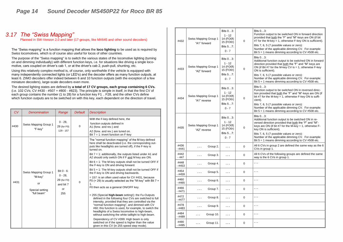
3.17 The “Swiss Mapping” Planned in SW-Version 2.0 and later (17 groups, like MX645 and other sound decoders)
The “Swiss mapping” is a function mapping that allows the loco lighting to be used as is required by Swiss locomotives, which is of course also useful for locos of other countries.
The purpose of the "Swiss mapping" is to switch the various states of the locomotive lighting (turning on and dimming individually) with different function keys, i.e. for situations like driving a single loco-motive, cars coupled on driver’s cab 1, or at the driver's cab 2, push-pull, shunting, etc.
Using this relatively complex method is, of course, only worthwhile if the vehicle is equipped with many independently connected lights (or LED’s) and the decoder offers as many function outputs, at least 6. ZIMO decoders offer indeed between 6 and 10 function outputs (with the exception of a few miniature decoders), large-scale decoders even more.
The desired lighting states are defined by a total of 17 CV groups, each group containing 6 CVs. (i.e. 102 CVs; CV #430 - #507 + #800 - #823). The principle is simple in itself, in that the first CV of each group contains the number (1 to 28) for a function key F1 .. F28, and the other CVs define which function outputs are to be switched on with this key, each dependent on the direction of travel.
CV Denomination Range Default Description
#430 Swiss Mapping Group 1
“F-key”
0 - 28,
29 (for F0)
129 - 157
0
With the F-key defined here, the
function outputs defined in A1 (forw. and rev.) and
A2 (forw. and rev.) are tuned on. Bit 7 = 1: invert function on F-key
#431
Swiss Mapping Group 1
“M-key”
or
Special setting “full beam“
Bit 0 - 6:
0 - 28,
29 (for F0)
and bit 7
or
255
0
The ”normal function mapping” of the M-key defined here shall be deactivated (i.e. the corresponding out-puts like headlights are turned off), if the F-key is turned on.
Bit 7 = 1: additionally, the outputs listed under A1 and A2 should only switch ON if F and M key are ON.
Bit 6 = 1: The M-key outputs shall not be turned OFF if the F-key is ON and driving forward.
Bit 5 = 1: The M-key outputs shall not be turned OFF if the F-key is ON and driving backwards.
= 157: is an often used value for CV #431, because F0 (= 29) is usually selected as the “M-key” with Bit 7 = 1. F0 then acts as a general ON/OFF key.
= 255 (Special high-beam setting!): the Fu-Outputs defined in the following four CVs are switched to full intensity, provided that they are controlled via the "normal function mapping", and dimmed with CV #60; this function is used, for example, to switch the headlights of a Swiss locomotive to high-beam, without switching the white taillight to high-beam.
Dependency of CV #399: High beam is only switched on if the speed is higher than the value given in this CV (in 255 speed step mode).
#432 Swiss Mapping Group 1
“A1” forward
Bits 0…3:
1 - 12 14 (FO0f) 15 (FO0r)
Bits 5…7:
0 - 7
0
Bits 0…3: Function output to be switched ON in forward direction provided that both the “F” and “M”-keys are ON (if bit #7 for the M-key = 1, otherwise F-key ON is sufficient).
Bits 7, 6, 5 (7 possible values or zero):
Number of the applicable dimming CV. For example: Bit 5 = 1 means dimming according to CV #508 etc.
#433 Swiss Mapping Group 1
“A2” forward
Bits 0…3:
1 - 12 14 (FO0f) 15 (FO0r)
Bits 5…7:
0 - 7
0
Bits 0…3: Additional function output to be switched ON in forward direction provided that both the “F” and “M”-keys are ON (if Bit #7 for the M-key CV is = 1, otherwise F-key ON is sufficient).
Bits 7, 6, 5 (7 possible values or zero): Number of the applicable dimming CV. For example: Bit 5 = 1 means dimming according to CV #508 etc.
#434 Swiss Mapping Group 1
“A1” reverse
Bits 0…3:
1 - 12 14 (FO0f) 15 (FO0r)
Bits 5…7:
0 - 7
0
Bits 0…3: Function output to be switched ON in reversed direc-tion provided that both the “F” and “M”-keys are ON (if bit #7 for the M-key = 1, otherwise F-key ON is suffi-cient).
Bits 7, 6, 5 (7 possible values or zero): Number of the applicable dimming CV. For example: Bit 5 = 1 means dimming according to CV #508 etc.
#435 Swiss Mapping Group 1
“A2” reverse
Bits 0…3:
1 - 12 14 (FO0f) 15 (FO0r)
Bits 5…7:
0 - 7
0
Bits 0…3: Additional function output to be switched ON in re-versed direction provided that both the “F” and “M”-keys are ON (if bit #7 for the M-key = 1, otherwise F-key ON is sufficient).
Bits 7, 6, 5 (7 possible values or zero): Number of the applicable dimming CV. For example: Bit 5 = 1 means dimming according to CV #508 etc.
#436 - #441
. . . Group 2. . . . 0 All 6 CVs in group 2 are defined the same way as the 6 CVs in group 1.
#442 - 447
. . . Group 3. . . . 0 All 6 CVs of the following groups are defined the same way is the 6 CVs in group 1.
#448 - #453
. . . Group 4. . . . 0 . . .
#454 - #459
. . . Group 5. . . . 0 . . .
#460 - #465
. . . Group 6. . . . 0 . . .
#466 - #471
. . . Group 7. . . . 0 . . .
#472 - #477
. . . Group 8. . . . 0 . . .
#478 - #483
. . . Group 9. . . . 0 . . .
#484 - #489
. . . Group 10. . . . 0 . . .
#490 - #495
. . . Group 11. . . . 0 . . .

Sound Decoder MS450P22 for Roco BR 85 Page 15
#496 - #501
. . . Group 12. . . . 0 . . .
#502 - #507
. . . Group 13. . . . 0 . . .
#800 - #805
. . . Group 14. . . . 0 . . .
#806 - #811
. . . Group 15. . . . 0 . . .
#812 - #817
. . . Group 16. . . . 0 . . .
#818 - #823
. . . Group 17. . . . 0 . . .
#508 #509 #510 #511 #512
Dimming values for “Swiss Mapping”
Special configurations
(0- 31)*8
(only bits 7…3 are
used)
Bits 0 - 2
0
Each group-CV (i.e. #432, #433, #434, #435) can be linked to one of these five dimming CVs.
This means that the function outputs shall be dimmed accordingly when switched on.
Usable only with function outputs FO0 to FO13.
Bit 0 = 1: suppresses the lighting effect (later software) Bit 1 = 1: flashing (later software) Bit 2 = 1: inverted flashing (later software)
#399
Speed dependent high beam
(Rule 17)
0 - 255 0
In conjunction with the “Swiss Mapping” special “high-beam” setting, see CV #431 = 255; applies to each of the 13 CV-groups (CV #437, 443..):
Switches to high-beam only when the speed exceeds the value in this CV; based on the decoder internal 255 speed steps.
EXAMPLE and SPECIAL CASES:
= 0: High-beam at any speed (incl. stand-still), con-trolled only by the F-key (i.e. as per CV #430).
=1: High-beam only while driving (not at stand-still), provided the defined F-key is ON.
= 128: Switches to high-beam when reaching medium speed.

Page 16 Sound Decoder MS450P22 for Roco BR 85
The application of the “Swiss Mapping” is shown here with
the example of an SBB Re422 engine. The function out-
puts together with the connected.
Lights or groups of lights are shown here as they exist in a typical SBB (Swiss) electric locomotive.
Task of the Swiss mapping here is to
show all possible operating states concerning the lighting (in both directions) correctly, using: F0 (general ON/OFF), and
F15, F16, F17, F18, F19, F20.
This results in a table, as you can see on the right wherefore for the “Swiss Mapping” in configured as follows:
#33 = 133 #34 = 42
#430 = 15 #431 = 157 #432 = 14 #433 = 1 #434 = 15 #435 = 1
#436 = 15 #437 = 157 #438 = 2 . #439 = 0 #440 = 2 . #441 = 0
#442 = 16 #443 = 157 #444 = 14 #445 = 1 #446 = 3 . #447 = 4
#448 = 17 #449 = 157 #450 = 5 #451 = 6 #452 = 15 #453 = 2
#454 = 18 #455 = 157 #456 = 6 #457 = 0 #458 = 4 #459 = 0
#460 = 19 #461 = 157 #462 = 2 #463 = 0 #464 = 1 #465 = 0
#466 = 20 #467 = 157 #468 = 0 #469 = 0 #470 = 0 #471 = 0
Explanation:
The normal NMRA function mapping in CVs #33 and CV #34 (front and rear headlight) determines the lighting in case F0 is ON and function keys F15 – F20 are OFF: CV #33 = 133 (= Lfor, FO1, FO6) and CV #34 = 42 (= Lrev, FO2, FO4).
The following CVs groups (1. Group: CV #430 – 435, 2. Group: CV #436 – 441 etc.), each group shown on one line, contain in the first CV the number of the “F-key” F15, F16, F17, F18, F19, F20, followed by the CVs for the “M-key” and function outputs to be switched.
Note that there are two groups for F15 (CV #430… and #436…) because F15 should switch 3 func-tion outputs simultaneously, but only 2 can be entered per group (A1, A2 for each direction); one group is sufficient for all other “F-Keys”.
All “M-Keys” (the second CV in each group) are all set to “157”; this means that “F0” and the condi-tion of Bit 7 must be met, which means that the selected outputs are only activated if the F- and M-keys are ON.
The third to sixth CVs in each group contain the numbers of the function outputs to be actuated (where the headlights are coded with “14” and “15”, for all other outputs just use the digit in FO1, FO2…).
Functions, Keys Outputs Front Rear
F0, forward (Cab 1 forward)
Lfor FO1 FO6
Locomotive only
F0, reverse (Cab 2 forward)
Lrev FO2 FO4
Locomotive only
F0 + F15, forward
(Cab 1 forward)
Lfor FO1 FO2
Train, cars coupled at cab 2, standard train without pilot car.
F0 + F15, reverse
(Cab 2 forward)
Lrev FO1 FO2
Train, cars coupled at cab 1, standard train without pilot car.
F0 + F16, forward
(Cab 1 forward)
Lvor FO1
Train, cars coupled at cab 2, standard train with pilot car or first engine in a double header.
F0 + F16, reverse
(Cab 2 forward)
FO3 FO4
Loco pushing, cars coupled to cab 2, with pilot car or first engine in a double header. (prototypical since 2000)
F0 + F17, reverse
(Cab 2 forward)
Lrev FO2
Loco pulling, cars coupled to cab 1, train with pilot car or first engine in a double header.
F0 + F17, forward
(Cab 1 forward)
FO5 FO6
Loco pushing, cars coupled to cab 1, with pilot car (prototypical since 2000).
F0 + F18, forward,
(Cab 1 forward)
FO6
Loco pushing, cars coupled to cab 1, with pilot car or last engine in a double header. (prototypical up to 2000)
F0 + F18, reverse
(Cab 2 forward)
FO4
Loco pushing, cars coupled to cab 2, with pilot car or last engine in a double header. (prototypical up to 2000)
F0 + F19, forward
(Cab 1 forward)
FO2
Loco pulling as last engine in consist, cars coupled to cab 2.
F0 + F19, reverse
(Cab 2 forward)
FO1
Loco pulling as last engine in consist, cars coupled to cab 1.
F0 + F20, forward/reverse --- Engine(s) inside a consist
FA6
Sound Decoder MS450P22 for Roco BR 85 Page 17
3.18 ZIMO “Input Mapping” Planned in SW-Version 3.0 and later!
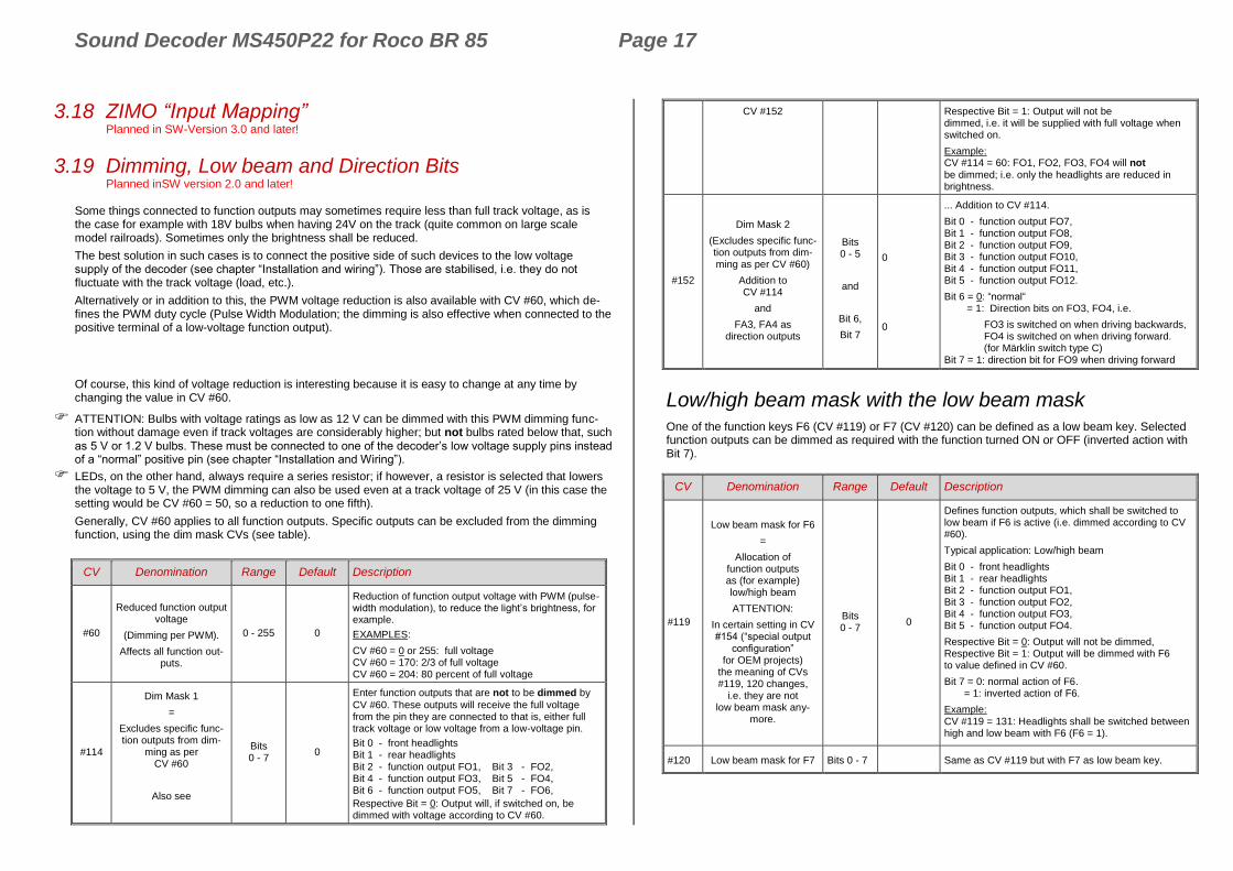
3.19 Dimming, Low beam and Direction Bits Planned inSW version 2.0 and later!
Some things connected to function outputs may sometimes require less than full track voltage, as is the case for example with 18V bulbs when having 24V on the track (quite common on large scale model railroads). Sometimes only the brightness shall be reduced.
The best solution in such cases is to connect the positive side of such devices to the low voltage supply of the decoder (see chapter “Installation and wiring”). Those are stabilised, i.e. they do not fluctuate with the track voltage (load, etc.).
Alternatively or in addition to this, the PWM voltage reduction is also available with CV #60, which de-fines the PWM duty cycle (Pulse Width Modulation; the dimming is also effective when connected to the positive terminal of a low-voltage function output).
Of course, this kind of voltage reduction is interesting because it is easy to change at any time by changing the value in CV #60.
ATTENTION: Bulbs with voltage ratings as low as 12 V can be dimmed with this PWM dimming func-tion without damage even if track voltages are considerably higher; but not bulbs rated below that, such as 5 V or 1.2 V bulbs. These must be connected to one of the decoder’s low voltage supply pins instead of a “normal” positive pin (see chapter “Installation and Wiring”).
LEDs, on the other hand, always require a series resistor; if however, a resistor is selected that lowers the voltage to 5 V, the PWM dimming can also be used even at a track voltage of 25 V (in this case the setting would be CV #60 = 50, so a reduction to one fifth).
Generally, CV #60 applies to all function outputs. Specific outputs can be excluded from the dimming function, using the dim mask CVs (see table).
CV Denomination Range Default Description
#60
Reduced function output voltage
(Dimming per PWM).
Affects all function out-puts.
0 - 255 0
Reduction of function output voltage with PWM (pulse-width modulation), to reduce the light’s brightness, for example.
EXAMPLES:
CV #60 = 0 or 255: full voltage CV #60 = 170: 2/3 of full voltage CV #60 = 204: 80 percent of full voltage
#114
Dim Mask 1
=
Excludes specific func-tion outputs from dim-
ming as per CV #60
Also see
Bits 0 - 7
0
Enter function outputs that are not to be dimmed by
CV #60. These outputs will receive the full voltage from the pin they are connected to that is, either full track voltage or low voltage from a low-voltage pin.
Bit 0 - front headlights Bit 1 - rear headlights Bit 2 - function output FO1, Bit 3 - FO2, Bit 4 - function output FO3, Bit 5 - FO4, Bit 6 - function output FO5, Bit 7 - FO6,
Respective Bit = 0: Output will, if switched on, be dimmed with voltage according to CV #60.
CV #152 Respective Bit = 1: Output will not be dimmed, i.e. it will be supplied with full voltage when switched on.
Example: CV #114 = 60: FO1, FO2, FO3, FO4 will not be dimmed; i.e. only the headlights are reduced in brightness.
#152
Dim Mask 2
(Excludes specific func-tion outputs from dim-ming as per CV #60)
Addition to CV #114
and
FA3, FA4 as direction outputs
Bits 0 - 5
and
Bit 6,
Bit 7
0
0
... Addition to CV #114.
Bit 0 - function output FO7, Bit 1 - function output FO8, Bit 2 - function output FO9, Bit 3 - function output FO10, Bit 4 - function output FO11, Bit 5 - function output FO12.
Bit 6 = 0: “normal“ = 1: Direction bits on FO3, FO4, i.e.
FO3 is switched on when driving backwards, FO4 is switched on when driving forward. (for Märklin switch type C) Bit 7 = 1: direction bit for FO9 when driving forward
Low/high beam mask with the low beam mask
One of the function keys F6 (CV #119) or F7 (CV #120) can be defined as a low beam key. Selected function outputs can be dimmed as required with the function turned ON or OFF (inverted action with Bit 7).
CV Denomination Range Default Description
#119
Low beam mask for F6
=
Allocation of function outputs as (for example) low/high beam
ATTENTION:
In certain setting in CV #154 (“special output
configuration” for OEM projects)
the meaning of CVs #119, 120 changes,
i.e. they are not low beam mask any-
more.
Bits 0 - 7
0
Defines function outputs, which shall be switched to low beam if F6 is active (i.e. dimmed according to CV #60).
Typical application: Low/high beam
Bit 0 - front headlights Bit 1 - rear headlights Bit 2 - function output FO1, Bit 3 - function output FO2, Bit 4 - function output FO3, Bit 5 - function output FO4.
Respective Bit = 0: Output will not be dimmed, Respective Bit = 1: Output will be dimmed with F6 to value defined in CV #60.
Bit 7 = 0: normal action of F6. = 1: inverted action of F6.
Example: CV #119 = 131: Headlights shall be switched between high and low beam with F6 (F6 = 1).
#120 Low beam mask for F7 Bits 0 - 7 Same as CV #119 but with F7 as low beam key.

Page 18 Sound Decoder MS450P22 for Roco BR 85
3.20 Flasher Effect Planned in SW-Version 3.0 and later!
3.21 F1 Pulse Chain Planned for later SW-versions
3.22 Special Effects for function outputs Planned in SW-Version 3.0 and later!

Sound Decoder MS450P22 for Roco BR 85 Page 19
3.23 Configuration of Smoke Generators
Smoke generator without fan (example: Seuthe 18V):
In addition to a simple ON/OFF function via a function output of your choice, the smoke intensity can also be programmed to change between standstill, or cruising and acceleration.
This requires the smoke generator to be connected to one of the function outputs FO1…FO8 and the se-lected output must be programmed for the desired effect with the associated “effect CV” (with CV #127 for FO1, CV #128 for FO2 etc.); in this case for load dependent smoke of steam engines (effect code “72”) or load dependent smoke of diesels (effect code “80”).
The smoke generator characteristic as defined by CVs #137, #138 and #139 is used for the relevant function output. These CVs must be programmed (with appropriate values) otherwise the smoke generator will not produce any smoke.
EXAMPLE: - Typical characteristic for a track voltage set around 20 V with above smoke generator (18 V):
CV #137 = 70 .. 90 Little smoke at standstill CV #138 = 200: The smoke intensity is increased to about 80% of its maximum capacity beginning with speed step 1 (at very low speed), which produces relatively heavy smoke. CV #139 = 255: The smoke generator is driven to its maximum under acceleration, which results in thick smoke.
Synchronized steam chuffs or typical diesel smoke (with exhaust fan):
The heating element of the smoke generator is connected – as in the example above with the “Seuthe” generator – on FO1…FO8. The fan is connected to the function output FO4 (in some de-coders on FO2). See chapter “Installation and wiring”.
CV Denomination Range Default Description
#133
Using FO4
as
cam-sensor output for the module of your
choice
or
FO4 as output for steam fan of the
smoke generator of steam locos
0, 1 0
= 0 (Default): FO4 is used as a normal function output and controlled by a function key, not a cam sensor.
= 1: FO4 is triggered by a cam sensor (synchronously to wheel rotation), usually for driving an exhaust fan. This is achieved with either the “virtual” or a real cam sensor. Also see CVs #267, #268!
NOTE: The fan operation is also determined by the sound project.
NOTE: large-scale decoders (which are not subject of this manual) have special outputs which offer more setting options for fans.
#137
#138
#139
Definitions of smoke generator char-acteristic, connected to
FO1 – FO6.
PWM at stand still
PWM at steady speed
PWM during accelera-tion
0 - 255
0 - 255
0 - 255
0
0
0
This is valid, if in one of the CVs #127 - #132 has set on of the function effects “smoke generation” (i.e. “72” or “80”): The values in CVs #137 – #139 define a characteristic for the function outputs (FO1 - FO8; re-ferred to below as FOx).
CV #137: PWM of FOx at standstill
CV #138: PWM of FOx at steady speed
CV #139: PWM of FOx at acceleration
3.24 Configuration of Electric Uncouplers Planned in SW-Version 3.0 and later!
3.25 SUSI-Interface and Logic-Level Outputs, Reed-Inputs Planned in SW-Version 3.0 and later!
3.26 Servo Configuration Planned in SW-Version 3.0 and later!
Page 20 Sound Decoder MS450P22 for Roco BR 85
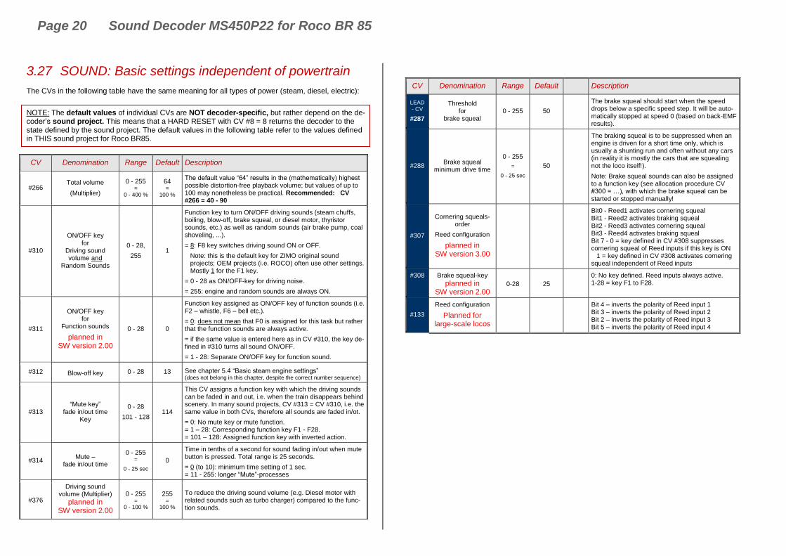
3.27 SOUND: Basic settings independent of powertrain
The CVs in the following table have the same meaning for all types of power (steam, diesel, electric):
NOTE: The default values of individual CVs are NOT decoder-specific, but rather depend on the de-coder’s sound project. This means that a HARD RESET with CV #8 = 8 returns the decoder to the state defined by the sound project. The default values in the following table refer to the values defined in THIS sound project for Roco BR85.
CV Denomination Range Default Description
#266 Total volume
(Multiplier)
0 - 255 =
0 - 400 %
64 =
100 %
The default value “64” results in the (mathematically) highest possible distortion-free playback volume; but values of up to 100 may nonetheless be practical. Recommended: CV #266 = 40 - 90
#310
ON/OFF key for
Driving sound volume and
Random Sounds
0 - 28,
255 1
Function key to turn ON/OFF driving sounds (steam chuffs, boiling, blow-off, brake squeal, or diesel motor, thyristor sounds, etc.) as well as random sounds (air brake pump, coal shoveling, ...).
= 8: F8 key switches driving sound ON or OFF.
Note: this is the default key for ZIMO original sound projects; OEM projects (i.e. ROCO) often use other settings. Mostly 1 for the F1 key.
= 0 - 28 as ON/OFF-key for driving noise.
= 255: engine and random sounds are always ON.
#311
ON/OFF key for
Function sounds
planned in SW version 2.00
0 - 28 0
Function key assigned as ON/OFF key of function sounds (i.e. F2 – whistle, F6 – bell etc.).
= 0: does not mean that F0 is assigned for this task but rather that the function sounds are always active.
= if the same value is entered here as in CV #310, the key de-fined in #310 turns all sound ON/OFF.
= 1 - 28: Separate ON/OFF key for function sound.
#312 Blow-off key 0 - 28 13 See chapter 5.4 “Basic steam engine settings” (does not belong in this chapter, despite the correct number sequence)
#313 “Mute key”
fade in/out time Key
0 - 28
101 - 128 114
This CV assigns a function key with which the driving sounds can be faded in and out, i.e. when the train disappears behind scenery. In many sound projects, CV #313 = CV #310, i.e. the same value in both CVs, therefore all sounds are faded in/ot.
= 0: No mute key or mute function. = 1 – 28: Corresponding function key F1 - F28. = 101 – 128: Assigned function key with inverted action.
#314 Mute –
fade in/out time
0 - 255 =
0 - 25 sec
0
Time in tenths of a second for sound fading in/out when mute button is pressed. Total range is 25 seconds.
= 0 (to 10): minimum time setting of 1 sec. = 11 - 255: longer “Mute”-processes
#376
Driving sound volume (Multiplier)
planned in SW version 2.00
0 - 255 =
0 - 100 %
255 =
100 %
To reduce the driving sound volume (e.g. Diesel motor with related sounds such as turbo charger) compared to the func-tion sounds.
CV Denomination Range Default Description
LEAD - CV
#287
Threshold for
brake squeal 0 - 255 50
The brake squeal should start when the speed drops below a specific speed step. It will be auto-matically stopped at speed 0 (based on back-EMF results).
#288 Brake squeal
minimum drive time
0 - 255
=
0 - 25 sec
50
The braking squeal is to be suppressed when an engine is driven for a short time only, which is usually a shunting run and often without any cars (in reality it is mostly the cars that are squealing not the loco itself!).
Note: Brake squeal sounds can also be assigned to a function key (see allocation procedure CV #300 = …), with which the brake squeal can be started or stopped manually!
#307
Cornering squeals-order
Reed configuration
planned in SW version 3.00
Bit0 - Reed1 activates cornering squeal Bit1 - Reed2 activates braking squeal Bit2 - Reed3 activates cornering squeal Bit3 - Reed4 activates braking squeal Bit 7 - 0 = key defined in CV #308 suppresses cornering squeal of Reed inputs if this key is ON 1 = key defined in CV #308 activates cornering squeal independent of Reed inputs
#308 Brake squeal-key
planned in SW version 2.00
0-28 25
0: No key defined. Reed inputs always active. 1-28 = key F1 to F28.
#133
Reed configuration
Planned for large-scale locos
Bit 4 – inverts the polarity of Reed input 1 Bit 3 – inverts the polarity of Reed input 2 Bit 2 – inverts the polarity of Reed input 3 Bit 5 – inverts the polarity of Reed input 4
NOTE: if a decoder has a mechanical volume regulator (especially large-scale decoders), it should NOT be turned on “full” volume, if high volume is not really desired (Loss of quality, if regulator is on “full” and volume is then reduced drastically by CVs).

Sound Decoder MS450P22 for Roco BR 85 Page 21
With the first SW version only a few CVs are active: (the first version is designed especially for BR 85);
with SW version 3.00 the expansion to general sound projects for steam locos is planned
Background sounds - Volume adjustments:
#574 “Simmering” 0 - 255 0 Volume driving sound “simmering”
Planned for later SW versions
#578 “Brake squeal” 0 - 255 0 Brake squeal volume
Planned for later SW versions
Planned for later SW versions
#584 Blow-off 0 - 255 0 Blow-off volume (STEAM engine)
Planned for later SW versions
Planned for later SW versions
Planned for later SW versions
Planned for later SW versions
Planned for later SW versions
Planned for later SW versions
Planned for later SW versions
Planned for later SW versions
Function sounds - Volume adjustments:
#571 Function sound F0 0 - 255
= 100, 1-100 %
0
Sound volume operated with function key F0
= 0: full volume, original sound sample volume (same as 255) = 1 - 254: reduced volume 1 - 99,5 % = 255: full volume
#514 #517 #520 #523
… #565 #568
Function sound F1 Function sound F2 Function sound F3 Function sound F4
… Function sound F18 Function sound F19
0 - 255 0
Sound volume operated with function key F1 Sound volume operated with function key F2 Sound volume operated with function key F3 Sound volume operated with function key F4 … Sound volume operated with function key F18 Sound volume operated with function key F19
#674 …
#698
Function sound F20 …
Function sound F28 0 - 255 0
Sound volume operated with function key F20 … Sound volume operated with function key F28
Note: The CVs between the above (#570, #572, #513, #515, #516, #518 etc.) hold information for the relevant sound samples (sample numbers, loop parameters etc.), which can also be modified if needed, usually with the CV #300 procedures.
Switch input sounds - Volume adjustments:
#739 Switch input sound S1 0 - 255
= 100, 1-100 %
0
Volume setting for the sound activated with switch input S1
= 0: full volume, original sound sample volume (same as 255) = 1 - 254: reduced volume 1 - 99,5 % = 255: full volume
#741 Switch input sound S2 0 - 255 0 Volume setting for the sound activated with switch input S2
#743 Switch input sound S3 0 - 255 0 Volume setting for the sound activated with switch input S3
#671 Switch input sound S4 0 - 255 0 Number of sound sample for input S4
#672 Switch input sound S4 0 - 255 0 Volume setting for the sound activated with switch input S4
Note: The CV immediately ahead of the CVs listed (#740, #742) contains the sound sample numbers to be played.
Random sounds - Volume adjustments:
#745 Random Sound Z1 0 Volume setting for sound activated by random generator Z1
#748 Random Sound Z2 0 Volume setting for sound activated by random generator Z2
#751 Random Sound Z3 0 Volume setting for sound activated by random generator Z3
#754 Random Sound Z4 0 Volume setting for sound activated by random generator Z4
#757 Random Sound Z5 0 Volume setting for sound activated by random generator Z5
#760 Random Sound Z6 0 Volume setting for sound activated by random generator Z6
#763 Random Sound Z7 0 Volume setting for sound activated by random generator Z7
#766 Random Sound Z8 0 Volume setting for sound activated by random generator Z8
Note: The CV immediately ahead of the CVs listed (#744, #747 etc.) contain the sound sample num-bers to be played. Possibility to adjust via ZCS (ZIMO CV Setting) tool.
Connection between sounds and function output:
#726 Connection 1 sound 0 Sound number which shall be valid for connection 1
#727 Connection 1 FO 0 Function output which shall be valid for connection 1. 1=FO0v, 2=FO0r, 3=FO1,….
#728 Connection 2 sound 0 Sound number which shall be valid for connection 2
#729 Connection 2 FO 0 Function output which shall be valid for connection 2. 1=FO0v, 2=FO0r, 3=FO1,….
#730 …
#735 … 0 …
#736 Connection 6 sound 0 Sound number which shall be valid for connection 6
#737 Connection 6 FO 0 Function output which shall be valid for connection 6. 1=FO0v, 2=FO0r, 3=FO1,….
Page 22 Sound Decoder MS450P22 for Roco BR 85
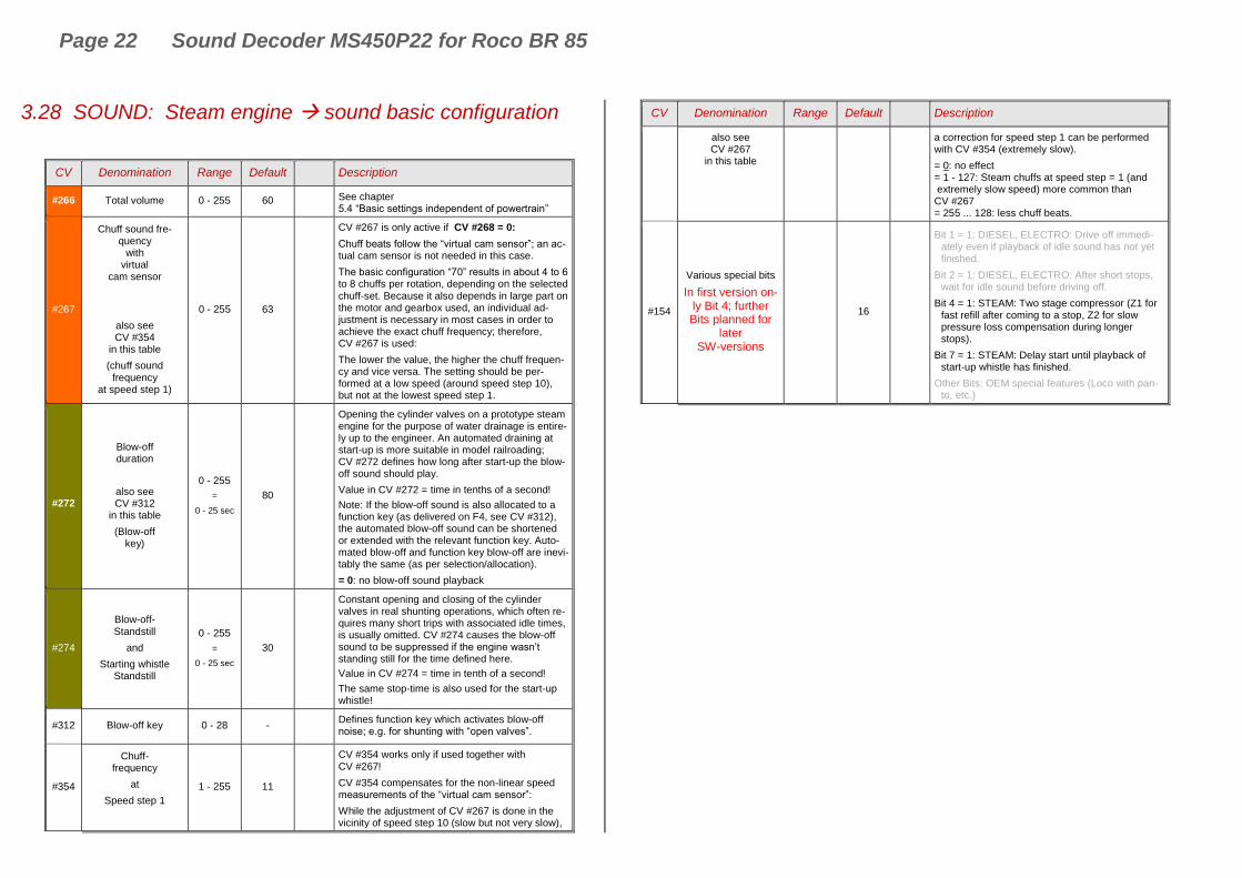
3.28 SOUND: Steam engine sound basic configuration
CV Denomination Range Default Description
#266 Total volume 0 - 255 60 See chapter 5.4 “Basic settings independent of powertrain”
#267
Chuff sound fre-quency
with virtual
cam sensor
also see CV #354
in this table
(chuff sound frequency
at speed step 1)
0 - 255 63
CV #267 is only active if CV #268 = 0:
Chuff beats follow the “virtual cam sensor”; an ac-tual cam sensor is not needed in this case.
The basic configuration “70” results in about 4 to 6 to 8 chuffs per rotation, depending on the selected
chuff-set. Because it also depends in large part on the motor and gearbox used, an individual ad-justment is necessary in most cases in order to achieve the exact chuff frequency; therefore, CV #267 is used:
The lower the value, the higher the chuff frequen-cy and vice versa. The setting should be per-formed at a low speed (around speed step 10), but not at the lowest speed step 1.
#272
Blow-off duration
also see CV #312
in this table
(Blow-off key)
0 - 255
=
0 - 25 sec
80
Opening the cylinder valves on a prototype steam engine for the purpose of water drainage is entire-ly up to the engineer. An automated draining at start-up is more suitable in model railroading; CV #272 defines how long after start-up the blow-off sound should play.
Value in CV #272 = time in tenths of a second!
Note: If the blow-off sound is also allocated to a function key (as delivered on F4, see CV #312), the automated blow-off sound can be shortened or extended with the relevant function key. Auto-mated blow-off and function key blow-off are inevi-tably the same (as per selection/allocation).
= 0: no blow-off sound playback
#274
Blow-off- Standstill
and
Starting whistle Standstill
0 - 255
=
0 - 25 sec
30
Constant opening and closing of the cylinder valves in real shunting operations, which often re-quires many short trips with associated idle times, is usually omitted. CV #274 causes the blow-off sound to be suppressed if the engine wasn’t standing still for the time defined here.
Value in CV #274 = time in tenth of a second!
The same stop-time is also used for the start-up whistle!
#312 Blow-off key 0 - 28 - Defines function key which activates blow-off noise; e.g. for shunting with “open valves”.
#354
Chuff- frequency
at
Speed step 1
1 - 255 11
CV #354 works only if used together with CV #267!
CV #354 compensates for the non-linear speed measurements of the “virtual cam sensor”:
While the adjustment of CV #267 is done in the vicinity of speed step 10 (slow but not very slow),
CV Denomination Range Default Description
also see CV #267
in this table
a correction for speed step 1 can be performed with CV #354 (extremely slow).
= 0: no effect = 1 - 127: Steam chuffs at speed step = 1 (and extremely slow speed) more common than CV #267 = 255 ... 128: less chuff beats.
#154
Various special bits
In first version on-ly Bit 4; further Bits planned for
later SW-versions
16
Bit 1 = 1: DIESEL, ELECTRO: Drive off immedi-ately even if playback of idle sound has not yet finished.
Bit 2 = 1: DIESEL, ELECTRO: After short stops, wait for idle sound before driving off.
Bit 4 = 1: STEAM: Two stage compressor (Z1 for fast refill after coming to a stop, Z2 for slow pressure loss compensation during longer stops).
Bit 7 = 1: STEAM: Delay start until playback of start-up whistle has finished.
Other Bits: OEM special features (Loco with pan-to, etc.)
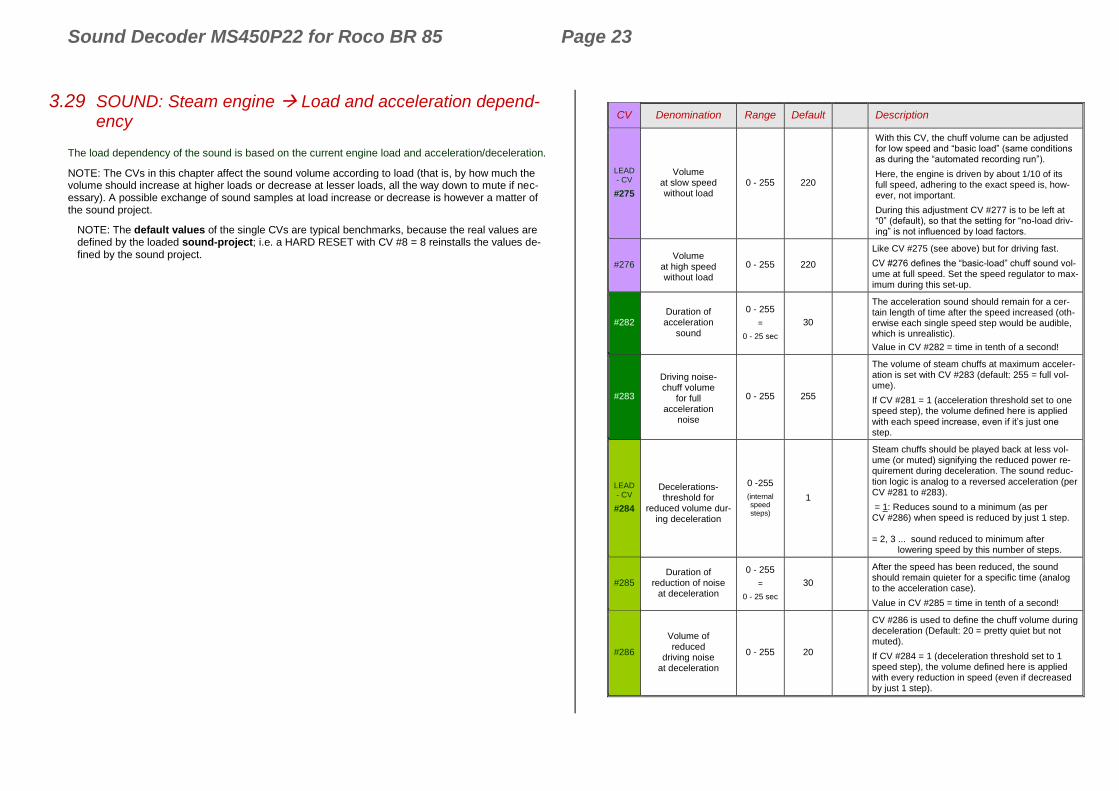
Sound Decoder MS450P22 for Roco BR 85 Page 23
3.29 SOUND: Steam engine Load and acceleration depend-ency
The load dependency of the sound is based on the current engine load and acceleration/deceleration.
NOTE: The CVs in this chapter affect the sound volume according to load (that is, by how much the volume should increase at higher loads or decrease at lesser loads, all the way down to mute if nec-essary). A possible exchange of sound samples at load increase or decrease is however a matter of the sound project.
NOTE: The default values of the single CVs are typical benchmarks, because the real values are defined by the loaded sound-project; i.e. a HARD RESET with CV #8 = 8 reinstalls the values de-fined by the sound project.
CV Denomination Range Default Description
LEAD - CV
#275
Volume at slow speed without load
0 - 255 220
With this CV, the chuff volume can be adjusted for low speed and “basic load” (same conditions as during the “automated recording run”).
Here, the engine is driven by about 1/10 of its full speed, adhering to the exact speed is, how-ever, not important.
During this adjustment CV #277 is to be left at “0” (default), so that the setting for “no-load driv-ing” is not influenced by load factors.
#276 Volume
at high speed without load
0 - 255 220
Like CV #275 (see above) but for driving fast.
CV #276 defines the “basic-load” chuff sound vol-ume at full speed. Set the speed regulator to max-imum during this set-up.
#282 Duration of acceleration
sound
0 - 255
=
0 - 25 sec
30
The acceleration sound should remain for a cer-tain length of time after the speed increased (oth-erwise each single speed step would be audible, which is unrealistic).
Value in CV #282 = time in tenth of a second!
#283
Driving noise- chuff volume
for full acceleration
noise
0 - 255 255
The volume of steam chuffs at maximum acceler-ation is set with CV #283 (default: 255 = full vol-ume).
If CV #281 = 1 (acceleration threshold set to one speed step), the volume defined here is applied with each speed increase, even if it’s just one step.
LEAD - CV
#284
Decelerations- threshold for
reduced volume dur-ing deceleration
0 -255
(internal speed steps)
1
Steam chuffs should be played back at less vol-ume (or muted) signifying the reduced power re-quirement during deceleration. The sound reduc-tion logic is analog to a reversed acceleration (per CV #281 to #283).
= 1: Reduces sound to a minimum (as per CV #286) when speed is reduced by just 1 step. = 2, 3 ... sound reduced to minimum after lowering speed by this number of steps.
#285 Duration of
reduction of noise at deceleration
0 - 255
=
0 - 25 sec
30
After the speed has been reduced, the sound should remain quieter for a specific time (analog to the acceleration case).
Value in CV #285 = time in tenth of a second!
#286
Volume of reduced
driving noise at deceleration
0 - 255 20
CV #286 is used to define the chuff volume during deceleration (Default: 20 = pretty quiet but not muted).
If CV #284 = 1 (deceleration threshold set to 1 speed step), the volume defined here is applied with every reduction in speed (even if decreased by just 1 step).