preferred knots for use in canyons
TRANSCRIPT

Bushwalkers Wilderness Rescue Squad
1
PREFERRED KNOTSFOR USE IN CANYONS
David Drohan
Abstract
On behalf of the Bushwalker’s Wilderness Rescue Squad (BWRS) Rock Squad, the author isconducting a series of tests in a voluntary capacity to determine the preferred knots that could beused in recreational canyoning. This paper will be of interest to all abseilers who have toretrieve their ropes. The project is planned for three stages. Stage one is now complete and thispaper focuses on the tensile strength and slippage of various knots. Cyclic loading and rope pulldown issues have also been investigated. 139 hours of actual testing has been conducted to date.This time does not include the considerable time to plan, analyse and write up the report.
This paper was presented at the Outdoor Recreation Industry Council NSW conference in Sept2001.
For further information regarding BWRS visit the web site at http://www.bwrs.org.au
Introduction
Recreational canyoning groups are questioning the traditional knots to join tape or rope. It hasbeen argued that the traditional Double Fisherman’s Knot (Figure 1-a) to join ropes is very tightto undo after use and often catches on obstacles during rope pull down. The Tape Knot (Figure1-b) can be difficult to adjust and now some groups have started using unconventional knotssuch as the Overhand Knot for joining rope or tape (Figure 1-c & d).
There is also evidence that some groups have been using smaller than usual size tape or cord foranchors, in order to reduce cost. This is done on the pretext that their group will only use theanchor sling once and they believe it is strong enough. It is commonly regarded that 50mm flattape or 25mm tube tape is acceptable for use in anchor slings. The project will explore if smallersize slings could be used, such as flat 25mm or maybe even 19mm polyester tape.
The proposal for this project was outlined in March 2000. This paper discusses tests conductedto determine various knot strengths, slippage and ease of rope pull down for various rope/tapematerials.
Literature Review
Existing Information on Ropes, Aging and Knot Strength/SlippageThe author has researched published information on the strength and slippage of knots in ropeand webbing. There is significant data on the rated strength of new tape and rope as indicated in

Bushwalkers Wilderness Rescue Squad
2
the sample of catalogues and specifications (see references). However only a couple ofreferences have been sighted that provide data on strength of knots tied in Kernmantle rope.Warild (1990 p33&34) provides information on recommended and non-recommended knotsshowing the static strength and falls taken for each knot. He states “the performance of mostknots is variable and depends on many factors, rope diameter, wet or dry, knot packing and to alesser extent temperature” (p33). He suggests the bulky knots appear to have a clear advantageespecially in 8 or 9 mm rope and the Overhand Loop (knot) performs inconsistently. WhilstWarilds’ tables are very helpful, the current author has not been able to access the test data onwhich they were based, and there are no test results for knot slippage. Luebben (1996, p7) alsoprovides some data on the strength of knots, but no supporting references are provided. Long(1993, p54), mentions that the Water (Tape) knot should be checked frequently, as it has thetendency to come untied.
Much testing has been conducted by the international organisation of alpine clubs, UnionInternationale des Association d’Alpinisme, (UIAA) on falling climbers and the equipment thatbreaks their fall. It is important to understand what causes the severity of the fall and sounderstand what is called a fall factor. Benk & Bram (Edelrid) describe the fall factor (FF) asthe proportion of fall and the length of rope run out. The fall factor describes the severity of thefall and determines the load on the entire system. The most serious fall a climber could take innormal circumstances is FF2, that is the length of free fall (say 20m) divided by the length ofrope paid out being (say 10 m) therefore 20/10 = 2. This means 10m of rope must absorb the fallenergy of a 20 m free fall. Abseilers do not take such extreme shock loads on their equipment.Warild (1990 p 15) argues that the worst fall factor a caver (abseiler) could take if one of the twoanchor bolts snapped would only be FF0.6. The probability of a FF0.6 fall is extremely low andthe most abseilers should ever expect for a well rigged rope is FF0.3. Warild states the mostconvincing evidence that caving (static) ropes are strong enough is the complete lack ofaccidents due to ropes failing under shock loads from caving (or abseiling in canyons).
Warild (1990, p 17) mentions ropes could be damaged by mechanical deterioration by 10 FF0.1minor shock loads, caused by prusiking or rough abseiling and suggests this is an avenue forinvestigation. One of the future tests in Stage 2 will explore this issue, as old ropes (that are toostiff to abseil on) are often used as back up anchor ropes.
Polyamide static ropes used for canyoning can be old. There is no “use by date” based only onage. The Blue Water Technical Manual (2001) provides information on when to retire yourstatic rope, such as damage from sharp edges, glazing from fast abseils or soft hollow or lumpysections in the rope. Replacement is based on wear and tear. Age is not mentioned as a limitingcriteria. What has been observed for ropes over 10 years old is that they often become too stiffto handle and abseil on. This is due to the mantle shrinking and so becomes less pliable. BlueWater recommends the shelf life for one of their unused dynamic ropes as five years. BlueWater admits there is no conclusive evidence from nylon manufacturers regarding aging ofunused ropes. Warild argues on p 17 that age does affect used ropes and gives data for a 4.5 yearold 9mm BWII rope that indicates it can only withstand four FF1 falls, where a new rope cantake 41 such shocks. AS4142.3 (1993) requires new 11mm static ropes used for rescue towithstand two FF2 falls. Provided the abseiler does not intentionally shock load the rope theway a climber could, age is not an issue, as polyamide static ropes can withstand some shockloading. Even with the worst normal abseiling shock load of FF0.6 the old rope should surviveone such shock load, as Warilds tests indicated the 4.5 year old rope could withstand four of thehigher FF1 falls. It appears aging affects a ropes ability to survive shock. The five-year ruleonly apples to dynamic ropes as they are designed for high shock loads. Static ropes are notrequired to be condemned when they reach five years old as they are not intended to take highshock loads.

Bushwalkers Wilderness Rescue Squad
3
Many rope manufacturers treat their rope with a “dry treatment”. This involves coating thenylon fibres of the rope with either silicon or teflon. Details on the process are difficult to obtainfrom manufacturers. This process is done so the rope will absorb less water when wet andtherefore maintain its strength. Warild (1990, p16) discusses that water absorption in nylon ropemakes it less abrasion resistant and reducing its static and shock strength by up to 30%. Some ofthe Edelrid ropes tested in this study were “dry” treated.
For natural laid fibre rope Marks Engineering Handbook (1987, p88) states that the shorter thebend in standing rope, the weaker the knot (based on Millers experiments 1900). However itappears to be a different story for nylon ropes. A report (the author wishes to remainanonymous), discovered that knots in Kernmantle (polyamide) rope failed at the point ofmaximum compression due to the knot compressing one strand of the rope sufficiently that theheat generated by friction caused the strand to become plastic and then fail.
Petzl (2000) (an outdoor gear manufacturer) provides some information on alternative knots ontheir web page technical manual, such as recommending the Abnormal Figure 8 Knot to join twoabseil ropes together. There is no supporting data for this recommendation. There is also usefuldata at this web site for UIAA limits and design criteria, such as that harnesses should not beloaded to more than 15kN.
Delaney (2000) from the Australian School of Mountaineering states he is not aware of anytesting of aged tape and rope as typically found in canyons and suggests there is only limitedinformation on knot slippage, but he could not provide any supporting test data.
Manufacturer’s Rated StrengthThe rated strength given by the product manufacturer is the minimum strength that the materialwill fail at, normally given in kilonewtons (kN). Most of the older equipment was rated inkilograms force (kg).
To convert to kg, multiply by 1000 (newtons) then divide by 10 (gravity rounded up).For example; a karabiner is marked as 22kN.22kN x 1000 = 22000(N) /10 = 2200 kg.A quick simple rule is just multiply kN by 100 to get kg.
Adequate testing of the product has been conducted by the manufacturer to determine the meanbreaking strength. Therefore the minimum or “rated” breaking strength can be determined. USand European companies that have extensive production undertake comprehensive testing oflarge samples from many batches. Therefore an accurate statistical figure can be determined.Some products like karabiners have a “Sigma 3” rating which is three standard deviations backfrom the mean. However many overseas companies only use two standard deviations back fromthe mean for rope and tape products.
To explain standard deviations (std dev), Freund (1988 p76) defines for the results that create anormal (bell shaped) distribution as follows:
About 68% of the values will lie within one standard deviation of the mean, hence about16% are outside the 1 std dev on the low side.About 95% of the values will lie within two standard deviation of the mean, hence onlyabout 2.5% are outside the 2 std devs on the low side.99.7% values will lie within three standard deviation of the mean, hence only about0.15% are outside the 3 std devs on the low side.
Some Aust/NZ rope/tape manufacturers do not use statistical calculations to determine theirrated strength for the materials used in this study. Toomer (2000) has clarified that the rated

Bushwalkers Wilderness Rescue Squad
4
strength used by Australian rope manufactures is based on a number of batch tests, using thelowest breaking specimen. Usually the rated strength is rounded down to the nearest 100 kg.Small (2000) from Donaghys Industries (a New Zealand webbing manufacturer) stated thewebbing (WPM25-OPG63 &WPM50-OA900) tested in this project is uncertified. The onlytesting conducted by the company on these products were by random sample and the “rated”load stated in the specification sheet is based on the minimum strength from the random testing.The random sample is based on three specimens from the end of a batch run. Batches were onlytested when the company had altered a part of the manufacturing process or for some otherreason. No statistical methods are employed to determine the minimum break load for randomsample tests.
Working Load LimitThe working load limit (WLL), sometimes referred to as the safe working load, is the maximumstatic load that should be applied to a rated piece of equipment. Dividing the rated strength bythe Safety Factor (SF) will give the WLL for that piece of equipment. Our example of akarabiner rated at 2200kg divided by SF5 for hardware will give a 440kg WLL.
Understanding Safety FactorsMost rope and hardware manufacturers give their product a rated strength. To determine theWLL a Safety Factor (SF) is used. Jensen (1974) describes safety factor as the ratio of ultimatestress (rated strength) to allowable stress (WLL). The safety factor is based on a number ofconsiderations including risk to human life, wear and tear of the product, aging and the type ofloading that may be encountered. To understand how SFs are determined, he gives examplesranging from 2 to 10 depending on the machine and application. Engineers have agreed that 5 isacceptable for lifting loads involving humans. SF5 has been adopted as the SF used for abseilingequipment hardware. Bateman & Toomer’s (1990) Australian Lightweight Vertical RescueInstructors (ALVRI) verbal advice during the course as recorded by the author, discuss that SF5is acceptable for hardware, however rope and tape must include a factor to account for loss ofstrength due to the knot.
ALVRI use a strength loss of one-third (33%) for any knot used in rescue. That is 0.67 strengthremaining in the rope. The original rope strength with no knot is divided by the strengthremaining due to knot of 0.67. This gives a ratio of 1.49. Multiplying the SF5 by this ratio of1.43 will give a figure of 7.46. This figure has been rounded up to give SF8.
Based on this rationale, AS 4142.3 (1993), notes the SF as not less than 8 is consideredappropriate. It is noted that the American Blue Water (2000) catalogue use the US Firedepartment’s SF15.
An appropriate SF is important. An excessive SF may add a significant weight or volumepenalty to the equipment you have to carry if you wish to maintain the existing WLLs. A SF thatis too low may lead to equipment failure with possible loss of life.
What else needs to be done?From the literature review it is clear there is still a lot to learn about knot strength and slippage inrope and tape. The tests conducted in this study provide further data on these issues however arenot exhaustive. Such a study would require access to research databases covering strength ofrope materials to determine the extent of research already conducted on this subject and how bestto build on this knowledge.
Project DesignThis project aimed to determine the best possible knot for joining ropes and slings together in acanyon. A useful side benefit was to identify any hazards evident in alternative knots. A process

Bushwalkers Wilderness Rescue Squad
5
of elimination determined the preferred knots. The knots being considered were eliminated in astep by step process based on the results from tests of A to E (listed below). The preferred knot(for each application) is the one that has the best results and has not been disregarded due to asafety issue.
The first stage of the process examined the static forces involved. The definition of “static” inthis case, is load not subjected to dynamic forces.
Objectives: Stage OneA. To determine the tensile strength and slippage of standard knots in slings.B. To determine the tensile strength and slippage of alternative knots that could be used to
join tape and rope.C. To determine the tensile strength of certain single strand ropes without knots.D. To determine if knots used to join slings or ropes slip under normal (cyclic) loading.E. To determine the ease of double rope pull down using various rope joining knots.
Section A is used as a baseline for the strength of standard knots. Section B compares thestrength of the alternative knots to Section A. Section C attempted to confirm the strength of therope/tape used in Sections A and B, without the influence of the knot on rope strength. Anyknots that were found unsafe after completion of Sections A to C were deleted from theremainder of the tests. Sections D and E are the final set of tests to examine the preferred knotsfor canyon use.
A further two stages of the project are planned to consider the shock forces and aging process.More information on these topics is provided under “Further Research” latter in this paper.
Method
Testing RequirementsIn order to maintain repeatability, reliability and validity of the tests the author has referred toappropriate Australian standards. No standard could be found that gave a procedure for tensiletesting of endless loops, therefore the author has adopted the philosophy of AS 4143.1(1993) forendless loop tests and has described the procedures followed in a later section of this paper.
For single strand rope testing AS 4143.1 (1993) is directly applicable and requires a gauge lengthof one metre (the distance between bollards) at the required pre-tensioned load. This indicates atest bed with a stroke of two to three metres would be required. Toomer (2000) from Spelean(an Australian rope manufacturer) indicated that the one metre length is important in order tohave enough material between the gauge lengths when compared with the material wrappedaround the bollards. The machines that the author had access to only had a maximum stroke ofone metre. In an attempt to solve this problem the author noted that in AS 2001.2.3 (1988) whichis one of the standards for testing seat belts, the procedure only required a gauge length of200mm. For this reason single strand tests using a gauge length of only 200mm were attempted.
There are no standards for conducting the cyclic and rope pull down tests in this project. Againthe author has described the procedures followed in a later section of this paper.
Clem (2000) (former chairman of the Life Safety Section of the Cordage Institute, USA)provided useful advice on the testing requirements for tensile and dynamic testing of knots. Hisfindings indicate apart from obvious criteria such as rope material and diameter, that moresubjective issues can come into play. These include which side the tail comes out of the knot. ieif the knot is tied right or left hand. The author has noted these concerns and attempts have been

Bushwalkers Wilderness Rescue Squad
6
made to record any unusual events during the tests by video recording a number of the tests andtaking individual notes on test records.Clem advises the absolute minimum size of the sample would be six specimens of the samematerial. It is acknowledged that the sample should be larger, however due to resourceconstraints the author has chosen six specimens per sample based on Clem’s advice. Although asample of six is less than ideal, AS 4143.1 (1993) only requires a report based on two successfultest specimens. Therefore the authors sample is three times greater than the relevant standardrequires.
Units used.The metric system of measurement has been used for this study.
Length measurements: millimetres (mm) are used for measurement up to one metre andmetres (m) for measurements greater than one metre.
Force measurement: kilonewtons (kN) have been used for the tensile tests. For thecyclic and rope pull down tests kilograms (kg) were used. As manufacturers rate theirequipment in kN it was decided the tensile tests would remain in that unit. AlthoughForce (Newtons) equals mass (kg) times gravity, it was decided for the other tests thatsimulated the weight of people and arm strength required to pull ropes down, it would besimpler to express the results of measurements as kg mass units.
The Tests of stage OneA. Tensile Strength and Slippage of Standard Knots in SlingsA tensile test machine was used to test the rated strength of new tape and old rope made up intoan endless sling by a knot. The slings were tested to failure. The joining knots were the TapeKnot for tape and the Double Fisherman’s Knot for rope.
B. Tensile Strength and slippage of Alternative Knots in SlingsA tensile test machine was used to test the rated strength of alternative knots in tape and ropemade up into endless slings.
C. Single Strand Tensile StrengthSingle strand of rope is the terminology used by rope manufacturers to describe a single lengthof rope, it is not a single fibre of rope. The testing conducted in A & B was for endless slings,the rating given in the manufacturer’s specification was doubled as a consequence. The doubledrating was compared to the second standard deviation back from the mean breaking strengthfrom each sample. This is not ideal due to statistical differences in the size of the two samplesbeing compared. To produce accurate values of strength loss due to a knot from the knot testsconducted in A& B, additional tests were conducted without a knot for the same material. Thiswould make it possible to compare the results to determine a true strength loss due to a knot.Single strand tests are required for this. It is also reasonable to compare the breaking strength ofthe aged material without a knot to the rated strength to determine the strength loss due to age ofthe material.
D. Knot Slippage caused by Cyclic LoadingKnot slippage under cyclic loading may be a more serious problem than slipping under aconstant load. Repeated predetermined loads were placed on the tape or rope slings. The knotswere measured for any slippage after each load application.
E. Canyon Rope Pull DownIn canyon abseils a double rope is slung around the anchor point and one end is pulled down toretrieve the rope after use. Tests were conducted to measure the force to pull a knot joining tworopes over various edges.

Bushwalkers Wilderness Rescue Squad
7
Knots Selected for Testing
There are many knots capable of tying rope or tape together. A knot used in a canyonenvironment must be safe. Safety in this context can be broken down into four sub headings. 3& 4 are considered safety issues due to the extra time to correct problems.1. Acceptable strength and slippage2. Easy to check3. Easy to tie and untie4. Suitable for the intended application. That is, the knot won’t catch on an edge during pull
down.These criteria were used to select the knots.
The following knots may meet the criteria. The project plan aimed to determine which knots metall of the above criteria.
(a) Double Fisherman’s Knot in rope (b) Tape Knot in tape
(c ) Overhand Knot in rope (d) Overhand Knot in tape
(e) Rethreaded Figure Eight Knot (f) Abnormal Figure Eight Knot
(g) Alpine Butterfly Knot (to tie ropes together)
Figure 1

Bushwalkers Wilderness Rescue Squad
8
Where applicable the knots were tied right-handed. There is an exception for one of theOverhand Knot pull down tests that also included a left-handed knot.
The Single Fisherman’s and Bowline to join ropes together were considered inappropriate due toknown slippage issues. The Rethreaded Overhand knot (a Tape Knot for rope) did not have anyobvious advantage over a Double Fisherman’s and so was not considered. Obviously dangerousknots such as the Reef Knot or various slip knots were dismissed.
Other knots such as the Reef Knot backed up with a Double Fisherman’s Knot and also theDouble Fisherman’s Knot to tie tape were eliminated before the testing began. The Reef backedup with a double fisherman’s has been used by some groups to overcome the issue of the DoubleFisherman’s Knot being too tight to undo after use. It is considered this knot is too complicatedand would be even more difficult due to its size to pull over a hard edge in rope pull down tests.
The author has heard of parties tying anchor tape with a Double fisherman’s knot. It is assumedthey consider this knot “fool proof” regarding slippage, however this knot uses a large amount oftape to tie and most canyoners do not distrust the Tape Knot enough to use this alternative knot.Therefore the author has decided not to test this knot.
Materials, Knot Packing, Preparation & Conditioning
Materials defined as new were purchased for the testing and were unused at the time of testing.Due to difficulties in accessing retailers purchase records, no attempt was made to determine thetime lapse between actual manufacture date and purchase date. The actual manufacture date wasnot printed on the tape reels. Dates of known ropes/tape of known age are based on the purchasedate.
Old rope is considered acceptable to use in these tests as this rope is sometimes used as canyonslings and always used as abseil ropes. A new rope can only be used new once! Variables werekept to a minimum to improve repeatability such as:
- Knowing the brand and age of the rope.- Ensuring the 6 specimens per test are cut from the same piece of rope.- Checking that any core or mantle damage is within the ALVRI guidelines.
Testing of some Sisal rope has been conducted, as canyoners may use this rope as slings in rarelyvisited canyons. This is done on environmental grounds, as it is believed sisal rope will rot andbreak down faster than nylon rope/tape when left in a canyon.
The material to be tested was formed into a sling (endless loop) by a joining knot. Figure 2details the naming convention of the knot. The “Tails” are the rope/tape knot tail ends and the“Tension” is the section of rope/tape that form the sling.
Figure 2 Knot Definitions

Bushwalkers Wilderness Rescue Squad
9
All knots in tape and rope were packed according to ALVRI guidelines. The guidelinesrecommend there shall be no cross overs in any part of the lay of the knot and the knot shall bepulled hand tight on each protruding section out of the knot to remove any rope slackness in theknot. The tails should be long enough to tie a thumb knot. When these procedures are followed,the knot should look neat in appearance and should not have any unnecessary slippage occurringunder normal load.
Although the length of a sling does not influence the load at which it will break, the authorconsidered it would still be useful to standardise sling length. This was achieved by the use of abollard jig for each machine. Due to the physical dimensions of each machine a standard sizesling was not possible for this stage of the project. The CIT machine sling length was 380±15mm. The ADFA machine sling length was 255 ±15mm.
Conditioning of dry samples to AS 4143.1 (1993) requires a standard atmosphere of 20 ±2 o Cand a relative humidity of 65 ±2%. Whilst not all testing was conducted in an air conditionedfacility, the temperature and relative humidity were monitored and testing was postponed if therelative humidity rose above 70% or the air temperature was less than 15 or greater than 30o C
Conditioning for the tensile test wet samples was in water between 14 and 17o C, for a durationof between 45 to 60 minutes which is considered appropriate to simulate a rope in a waterfallwhilst people are abseiling. For the tensile tests refer to Annex B Sheet 2 to determine which wetsamples were dry treated.
For the cyclic tests the rope/tape samples were not “dry” treated. Wet test specimens were tiedinto slings whilst dry, then placed into a bucket of cold water for approximately 10 minutesbefore the test. As each set of tests took 3 hours to conduct, cold water was poured onto the 6th
and 10th cycle to prevent drying out. Dry tests were only conducted when the relative humiditywas less then 67%, due to humidity possibly affecting the results by moisture tightening the knotand thus reducing slippage.
Equipment
Tensile Testing MachinesTwo tensile testing machines were used to conduct the tensile tests. One is located at theMechanical Test Laboratory; Bruce Canberra Institute of Technology (CIT) (ACT). The other isat the Civil Engineering Test Laboratory - Australian Defence Force Academy (ADFA) (ACT).
Bruce CITThe machine at Bruce CIT (Figure 3-a&b) is a Shimadzu universal tensile testing machine, ratedto 25 tonne and is currently certified by the National Association of Testing Authorities (NATA)as a Class A machine for all loads in range. This machine can produce load elongation graphs,unfortunately they can not be scaled and are only to be used as a guide. On this machine thegauge length was measured between the cross heads on the machine. The author worked incollaboration with the technical officer responsible for the operation of the machine. The CITlaboratory is maintained to the necessary temperature and humidity requirements.
Bushwalkers Wilderness Rescue Squad
10
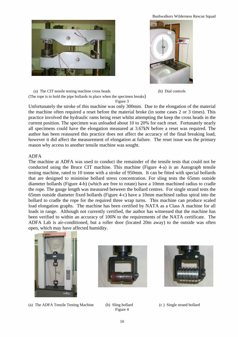
(a) The CIT tensile testing machine cross heads (b) Dial controls(The rope is to hold the pipe bollards in place when the specimen breaks)
Figure 3Unfortunately the stroke of this machine was only 300mm. Due to the elongation of the materialthe machine often required a reset before the material broke (in some cases 2 or 3 times). Thispractice involved the hydraulic rams being reset whilst attempting the keep the cross heads in thecurrent position. The specimen was unloaded about 10 to 20% for each reset. Fortunately nearlyall specimens could have the elongation measured at 3.67kN before a reset was required. Theauthor has been reassured this practice does not affect the accuracy of the final breaking load,however it did affect the measurement of elongation at failure. The reset issue was the primaryreason why access to another tensile machine was sought.
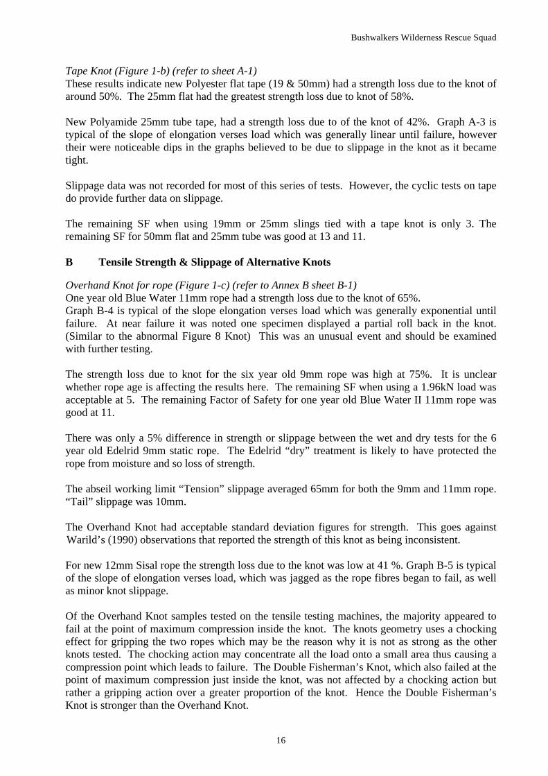
ADFAThe machine at ADFA was used to conduct the remainder of the tensile tests that could not beconducted using the Bruce CIT machine. This machine (Figure 4-a) is an Autograph tensiletesting machine, rated to 10 tonne with a stroke of 950mm. It can be fitted with special bollardsthat are designed to minimise bollard stress concentration. For sling tests the 65mm outsidediameter bollards (Figure 4-b) (which are free to rotate) have a 10mm machined radius to cradlethe rope. The gauge length was measured between the bollard centres. For single strand tests the65mm outside diameter fixed bollards (Figure 4-c) have a 10mm machined radius spiral into thebollard to cradle the rope for the required three wrap turns. This machine can produce scaledload elongation graphs. The machine has been certified by NATA as a Class A machine for allloads in range. Although not currently certified, the author has witnessed that the machine hasbeen verified to within an accuracy of 100N to the requirements of the NATA certificate. TheADFA Lab is air-conditioned, but a roller door (located 20m away) to the outside was oftenopen, which may have affected humidity.
(a) The ADFA Tensile Testing Machine (b) Sling bollard (c ) Single strand bollardFigure 4

Bushwalkers Wilderness Rescue Squad
11
Knot Cyclic Testing RigA rig has been built to simulate the cyclic loads that occur when a rope is abseiled on, severaltimes. The rig was set up to measure any slippage in knots caused by this type of cyclic loading.A sling tied with the knot to be tested was suspended from an overhead structure.(Figure 5-a)Each knot was marked so any slippage in the tail or out of the sling could be measured.Measurements were taken in the unloaded condition. Either 50 or 100kg of weight were hungfrom the sling. Any slippage was measured when the sling was loaded (Figure 5-b). The slingwas then unloaded using appropriate mechanical advantage, and was shaken for five seconds tosimulate possible knot loosening by wind or handling by an abseiler. The sling was thenreloaded and another set of measurements taken. This process was repeated 15 times. TheFigure of 15 was considered appropriate for a maximum number of people likely to be abseilingthe pitch.
(a) (b)(a) The cyclic testing rig showing the sling, the weight and the rope mechanical advantage for lifting the weight.(b) Sling tape showing the slippage marks on the “Tension” side.
Figure 5
Rope Pull Down Friction Measurement RigAny one who has been canyoning will know how varied the required force to pull down abseilropes can be. Force can range from one hand for a 5m drop through to three people hanging offthe rope under a waterfall to slowly move it down past 50m of friction points. Due to all thepossible variables it was decided one standard cliff site would be used. Trial tests at Wee Jasperindicated a 15m cliff was acceptable to provide the required friction within the spring balancerange.
Two sets of tests were planned using a natural and an artificial 90o hard edge for both dry andwet conditions. The first waterfall on Bungonia creek was selected as a good site to conduct thetests.
The 9mm static ropes used in this series of tests had no dry treatment applied.
Permission was gained from the Bungonia NPWS ranger to conduct a BWRS Rock Squadtesting day held at the first waterfall in Bungonia Creek. The cliff edge consisting of volcanicquartz has two points of contact for the rope with the edges at 25o and 20o off vertical. Theanchor sling was angled at 40o above horizontal. The natural edge does not have a problem withexcessive friction. As can be seen from Figure 6-a, a V shape groove could catch certain knots.There was a ledge 12.5m from the top edge to take load measurements from.
Two knot pull down tests were conducted, one on the natural cliff edge and for the second aBessa block was used for the hard edge tests. Unfortunately the Bessa block could not be

Bushwalkers Wilderness Rescue Squad
12
secured sufficiently to prevent movement, therefore the hard edge tests were invalid. Lack oftime prevented the wet tests from being conducted.
(a) The Bungonia cliff detailing the knot going (b) Profile of the Bungonia cliff edge. over the 25o edge
Figure 6
In order to complete valid hard edge tests, the authors garage roof (Figure 7-a) was selected. Theroof is 2.7m high and 2x4m lengths of 9mm static ropes tied together with the knot to be testedwere used. A concrete Bessa block was secured so it would not move under rope loads. Asecond block was used to position the anchor pivot point. The tests were standardised by usingthe block in the same position for all tests. A Spring balance has been used to measure the forcerequired to start moving the knot over a 90o reverse edge and going over the 90o obtuse edge.Significant friction within the measurement range of the spring balance was obtained without theneed to simulate the weight of hanging rope. Trial tests determined that the 1.5kg weights (tosimulate 25m of free hanging rope) on each rope end were not required due to the 45kg springbalance exceeding its limit.
(a) The author using a spring balance to measure the load (b) The profile of the edges used for when pulling a knot over a 90 0 edge at his garage. the garage
Figure 7
The rate of travel used in this series of tests was determined to be approximately 2 seconds permetre of rope pulled, ie 0.5m/s. This rate of travel was considered appropriate in order to read

Bushwalkers Wilderness Rescue Squad
13
the spring scales. In actual canyon rope pull down situations the rate of travel of a person pullingdown the ropes may be twice the speed for small pitches. There was evidence that fast rope pulldowns sometimes required less load to pass over the edge. Unfortunately trial tests determined itwas not possible to measure the load on the spring balance in the fast rope pull down tests,therefore the results obtained may be conservative.
The hard edge (Figure 7-b) is considered one of the harshest edges that could be encountered soit is a good edge to test the knots being examined. For the wet tests a garden hose was used tocontinually spray water over the Bessa block.
Loads & Test WeightsIn simulating the loads that could be applied in canyoning, the load of two people abseiling atonce on a double rope (twin person or assisted abseiling) is used, as this load is the heaviest loadthat should be applied in the recreational activity of canyoning. ALVRI use a standard weight of100kg for one person. Therefore the load of 200kg (1.96kN) is used to simulate two people onthe abseil rope. The 200kg weight should be the WLL of ropes and tape used for canyonabseiling.
AS 4142.3 (1993) states 3.67kN (375kg) is the WLL for a rescue rope. Collecting strength andslippage data at this load will be of use to the rescue community.
Slippage measurements have been recorded when the tensile test machine reached a load of1.96kN and 3.67kN. A final set of records have been taken when the test specimens failed.Load verses elongation graphs have been produced by the tensile test machines.
For the Cyclic Loading tests, the aim was to determine if greater slippage at the knot wouldoccur by the repeated application of a lighter load when compared to a standard 200 kg loadapplied only once. A load of 50kg representing a teenager and a load of 100kg representing anadult has been used in this series of tests. The cyclic loading test weights are made up of acluster of calibrated 10kg and 20kg weights provided by Bruce CIT.
Test Apparatus and Measurement EquipmentThe tensile test machines were pretensioned, as required by AS4143.1 (1993). For each 9mmrope and tape specimen pretensioning was set at 0.1kN. For 11mm rope specimens the settingwas 0.15kN. With the specimen pretensioned between the bollards of the tensile test machine,the gauge mark length was measured with a tape measure. This was the zero load measurement.The gauge length is defined as a mark on each bollard structure to which measurements weretaken to determine sling elongation. Elongation measurements were taken at zero load, 1.96 kN(200 kg), 3.6 kN (375 kg) and failure.
The tensile test machines crosshead rate of travel was set at 40mm per minute.
All tensile tests had the knot positioned mid away on the sling between the bollards. Refer toFigure 4-a, photograph of the ADFA machine that shows a typical sling set up.
Vernier callipers were used to measure knot slippage. The specimens were marked at the fourprotrusions from the knot with a suitable contrasting coloured pen (that would not affect thestrength of the material). The tail lengths were measured at zero load, as it was expected the tailswould shorten and the marks would move within the knot. Tail lengths were then measured ateach predetermined load. The mean “Tail” slippage could then be calculated. The “Tension”slippage data provided is the summation of the two measurements taken between the mark andthe knot. Measurements were taken at each predetermined load by stopping the tensile testingmachine long enough to record the dimensions. Care was taken to place the vernier callipers on

Bushwalkers Wilderness Rescue Squad
14
the same section of the test specimens for all the readings. Accuracy is believed to be within ±1mm.
A spirit level, adjustable protractor and a 30m tape measure were carried into the Bungoniawaterfall site to survey the cliff edge (Figure 6b). A Bessa block was carried in (and out) for thehard edge tests.
Two spring balance scales rated to either 25kg or 45kg were available for the rope pull downtests. If loads were higher than 25kg then the 45kg scale was used. The load on the scale wasnoted as the knot moved each time. Reading accuracy was assessed to be within ±1kg using thismethod. The 25kg spring balance was calibrated using test weights of 5kg 10kg & 20kg and wasfound to be accurate. The 45kg spring balance was calibrated using test weights of 5kg, 10kg,20kg, 30kg & 40kg and found to require a correction for accuracy. A correcting factor has beenapplied to the results of the 45kg spring balance readings.
Results
Refer to the Annexes A to E for tables and graphs of the results of this study. Annex C is notused as this series of tests was not successful.
Discussion
The knot strength losses quoted in this report are for percentage strength loss due to a knotcompared to the rope strength. Manufacturers tend to provide rated strength as percentageremaining in the material. Annexes A&B also tabulate the strength data as percentage strengthremaining in the rope for reference only.
Statistical data is given for strength data to determine the lowest breaking strength based on 2standard deviations (std devs) back from the mean. 2 std dev was chosen as the sample was toosmall for 3 std devs to give a meaningful number. Additional most overseas manufacturers use 2std devs for their ratings.
The ramifications of relatively small samples and the approach to comparisons means there issome statistical uncertainty. It is therefore not possible to state the values for knot strength inabsolute terms. However, the strength data provided can be used as a general guide.
Slippage data discussed in the paper is at the abseil working load of 1.96kN. The slippage dataprovided in Annex A & B is given at the loads of 1.96kN (200kg), 3.67kN (375kg) and failure.The slippage data is a guide only. Standard deviation calculations were completed for thesemeasurements but have not been reported. There was significant scatter from the mean (up to30%) and it is believed the sample would have to be much greater to provide conclusivestatements about rope/tape slippage.
The slippage data presented in Annex A & B for the1.96 and 3,67kN loads could not be obtainedfor some materials when using the CIT machine. This was due to the large cross headsobstructing access to the specimens. Refer to Figure 3 (a) for a photograph of the cross heads.
The remaining factor of safety of the material is determined relative to a 1.96kN (200kg) load.Dividing the knot’s 2 std dev breaking strength back from the mean by the 1.96kN load derivesthis safety factor. The equation for this is SF=(Mean breaking load –2 std devs)/Abseil WLL

Bushwalkers Wilderness Rescue Squad
15
For this case the breaking load includes the weakness of the knot. Therefore an additional knotfactor is not included in this safety factor. As a result of this logic, the safety factor for anymaterial should always be greater than 5. (SF5 is for loads involving humans)
Results AnalysisKnot Age & Material Sling Breaking
Strength 2 StdDev back fromMean (kN)
Mean "Tail"slippage at 1.96kN (mm)
Total "Tension"slippage at 1.96 kN(mm)
Loss ofStrengthdue to knot
TapeTape
New 50mm flat tapeNew 25mm tube tape
24.6421.52
Not recorded
Not recorded
Not recorded
Not recorded52%42%
Double Fisherman’s 1 year old 11mm static rope 36.43 5 48 42%Rethreaded Figure 8 1 year old 11mm static rope 30.11 1 45 52%Overhand new 50 mm flat tape 17.94 25 Not recorded 65%Overhand 1 year old 11mm static rope 22.05 12 51 65%Abnormal Fig 8 15 year old 11mm static rope 24.10 16 203 62%Alpine Butterfly 1 year old 11mm static rope 29.97 14 54 52%
Table 1Summary of Strength Loss due to Knot & Slippage
For detailed information refer to Annex A & B
Table 1 provides an abridged summary of the strength loss due to knot & slippage data that isprovided in Annex A and Annex B. The following discussion refers to these Annexes, this tableis provided for quick reference.
A. Tensile Strength & Slippage of Standard Knots in Slings
Double Fisherman’s Knot (Figure 1-a) (refer to sheet A-2)One year old Blue Water 11mm rope had a strength loss due to the knot of 42%. The 18 year oldBlue Water 11mm rope had a strength loss of 70%. The difference between the 1 and 18 yearold rope tied with the same knot is 28%. It appears the aging of the old rope may account for a≅30% strength loss.
Graph A-4 is typical of the slope of elongation verses load which was generally non-linear.
For new 10mm & 12mm Sisal rope the strength loss due to the knot was 36% & 9 %. The 9%may be explained, if the manufacturer’s rated strength included a knot. It could also beexplained if the manufacturers rated strength for the rope was 3 standard deviations below themean rope breaking strength. Then a sample of rope well above the rated strength would givethe low apparent strength reduction.
Graph A-5 is typical of the slope of elongation verses load which was very jagged due to therope fibres in the knot beginning to fail, as well as minor slippage in the knot.
New 7mm & 9mm Riviory rope gave unexpected results of 2% & 6 % strength loss due to theknot.
The abseil working load “Tension” slippage averaged out at 49mm for both 9mm and 11mmrope. The “Tail” creep was 6mm at this load. The sisal rope slipped less than the kermantle rope.Its “Tension” slippage was only 30mm due to the laid strands locking and thus reducingslippage.
The remaining SF for 10mm Sisal rope was only 4. All other materials tested had SFs in excessof 5
Bushwalkers Wilderness Rescue Squad
16
Tape Knot (Figure 1-b) (refer to sheet A-1)These results indicate new Polyester flat tape (19 & 50mm) had a strength loss due to the knot ofaround 50%. The 25mm flat had the greatest strength loss due to knot of 58%.
New Polyamide 25mm tube tape, had a strength loss due to of the knot of 42%. Graph A-3 istypical of the slope of elongation verses load which was generally linear until failure, howevertheir were noticeable dips in the graphs believed to be due to slippage in the knot as it becametight.
Slippage data was not recorded for most of this series of tests. However, the cyclic tests on tapedo provide further data on slippage.
The remaining SF when using 19mm or 25mm slings tied with a tape knot is only 3. Theremaining SF for 50mm flat and 25mm tube was good at 13 and 11.
B Tensile Strength & Slippage of Alternative Knots
Overhand Knot for rope (Figure 1-c) (refer to Annex B sheet B-1)One year old Blue Water 11mm rope had a strength loss due to the knot of 65%.Graph B-4 is typical of the slope elongation verses load which was generally exponential untilfailure. At near failure it was noted one specimen displayed a partial roll back in the knot.(Similar to the abnormal Figure 8 Knot) This was an unusual event and should be examinedwith further testing.
The strength loss due to knot for the six year old 9mm rope was high at 75%. It is unclearwhether rope age is affecting the results here. The remaining SF when using a 1.96kN load wasacceptable at 5. The remaining Factor of Safety for one year old Blue Water II 11mm rope wasgood at 11.
There was only a 5% difference in strength or slippage between the wet and dry tests for the 6year old Edelrid 9mm static rope. The Edelrid “dry” treatment is likely to have protected therope from moisture and so loss of strength.
The abseil working limit “Tension” slippage averaged 65mm for both the 9mm and 11mm rope.“Tail” slippage was 10mm.
The Overhand Knot had acceptable standard deviation figures for strength. This goes againstWarild’s (1990) observations that reported the strength of this knot as being inconsistent.
For new 12mm Sisal rope the strength loss due to the knot was low at 41 %. Graph B-5 is typicalof the slope of elongation verses load, which was jagged as the rope fibres began to fail, as wellas minor knot slippage.
Of the Overhand Knot samples tested on the tensile testing machines, the majority appeared tofail at the point of maximum compression inside the knot. The knots geometry uses a chockingeffect for gripping the two ropes which may be the reason why it is not as strong as the otherknots tested. The chocking action may concentrate all the load onto a small area thus causing acompression point which leads to failure. The Double Fisherman’s Knot, which also failed at thepoint of maximum compression just inside the knot, was not affected by a chocking action butrather a gripping action over a greater proportion of the knot. Hence the Double Fisherman’sKnot is stronger than the Overhand Knot.

Bushwalkers Wilderness Rescue Squad
17
Overhand Knot for tape (Figure 1-d) (refer to sheet B-1)For new Polyester flat tape (25mm & 50mm), the strength loss due to the Overhand Knot wasbetween 61 to 65%. The remaining SF when using a 1.96kN load for the 25mm flat and 25mmtube tape was only 3. For the wet and dry 50mm flat samples, the remaining SF was between 9and 10.There was no major difference in strength or slippage between wet and dry tests for 25 or 50mmflat polyester tape.
The result for the three-year-old Polyamide 25mm tube tape, which had a strength loss due to theknot of 82%, was alarming. Mean breaking strength was only 7.16kN and the standard deviationof the sample tested was very small at 0.42 (indicating very repeatable results). If the materialwere new, it is estimated the breaking strength would be 12.6kN. The results give a breakage56% less then what was expected. It seems unlikely the ageing effect would be this bad for tapethat was only bought in June 97. The sample had been used as a club hand line during that timeand had been stored appropriately when not in use. Although the sample tape was dirty (It waswashed and dried before testing) no serious abrasion was detected apart from some minorfluffing.
Graph B-3 is typical of the slope of elongation verses load which was generally linear untilfailure.
Rethreaded Figure Eight Knot (Figure 1-e) (refer to Annex B sheet B-2)One year old BW 11mm rope had a strength loss due to the knot of 52%.The new 7mm and 9mm Rivory rope had a low strength loss due to the knot of 24% and 30%respectively. The remaining SF with the 1.96kN load for the 9mm and 11mm ropes wereexcellent at 13 and 15 respectfully and acceptable for the 7mm cord at 8.
The abseil working limit “Tension” slippage averaged at 44mm. Average “Tail” slippage wasonly 1mm. This knot had the least slippage (especially tail) when compared to the other knots ofthe same material.
Abnormal Figure Eight Knot (Figure 1-f) (refer to Annex B sheet B-2)Breaking strength was similar averaged at 14.8kN between the two Edelrid wet and dry samples.This was probably due to the “dry” treatment on this rope. Strength loss due to knot wasbetween 62% to 64%, however this rope was aged. The breaking strength of the older Bluewater 9mm rope sample was a lot stronger at 24.1kN compared to the two Edelrid samples thatwere not as old.
All 9mm rope specimens tested had at least one roll back, four rolled back twice and onespecimen rolled back three times. The lowest first roll back occurred at 2.1kN ( the weight oftwo abseilers) Graph B-6 is typical of the slope on the graph of elongation verses load, whichwas dramatic, as the knot displayed either partial or complete roll-backs.
Significant “Tension” slippage was already occurring at the abseil-working load, with an average“Tension” slippage of 165mm. “Tail” slippage was only an average of 10mm.
Average “Tension” slippage at failure for the 3 sets of tests conducted was 410mm. On onespecimen the “Tail” had slid in 120mm to the point where the tail was flush with the knot beforeit broke. Another specimen had a “Tension” slippage of 633mm at failure. No significantslippage difference was noted between wet and dry samples.
Another example of how dangerous this knot can be is to tie the knot with inappropriate taillengths and have the knot poorly packed. In this configuration, it is possible for two people

Bushwalkers Wilderness Rescue Squad
18
pulling in a tug of war fashion (which equates to approximately a 50kg load) to pull the knotcompletely apart. For the reason of roll back and knot failure this knot was deleted from furthertesting.
Alpine Butterfly Knot (Figure 1-g) (refer to Annex B sheet B-2)One year old 11mm rope had a strength loss due to the knot of 52%. The six year old rope wasbetween 59 and 66%. Remaining SF with the 1.96kN load was very good, being between 12 and16. From a strength point of view, this knot performed very well. The large majority of thespecimens broke at the top or bottom bollard indicating the knot was very strong. The lowerstrength of the older rope may be due to an aging factor.
It was interesting to note the difference between the dry and wet samples. All specimens fromthe dry sample had uniform slippage as load was applied and there was still some slippage asload approached failure. The wet sample was interesting in that the knot would hold then slip allof a sudden, hold then slip again. Graph B-7 is typical of this noted occurrence.
The abseil working limit “Tension” slippage averaged at 74mm. Average “Tail” slippage was14mm.
Horrocks (2000) discovered this knot (when used to tie two ropes together) could easily be tiedthe wrong way resulting in the knot possibly undoing under load with obvious deadly results forany abseiler on the rope. This fact was pointed out to the author soon after this set of tests wascompleted. Two people pulling on the rope in a tug of war fashion can demonstrate this. It isnot apparent to casual visual inspection that the knot is tied incorrectly. Due to this issue, theAlpine butterfly knot was deleted from further testing.
Knot Strength ComparisonsThe results of Section A and B have been summarised into Table 2 as sourced by the author.This table also compares the present data to other published sources.
TYPE OF ROPE JOINING KNOT
Source TAPE OVERHAND INTAPE
DOUBLEFISHERMAN'S
RETHREADEDFIGURE 8
OVERHAND ALPINEBUTTERFLY
DROHAN 42% & 52% 65% 42% 52% 65% 52%
Wild Sports (11 & 9mm) - - 12% & 22% - - 24% & 34%
Luebben 30-40% - 30-35% - 35-40% -
Warlid (mainly 10mm) 55% - 45% 50% 55% 53%
Table 2Knot Strength Comparisons
Percentages given are for strength loss due to a knotDrohan’s results are for New Donaghys 50mm tape and 1 year old BWII 11mm rope
The present results compare well to Luebben (1996) and Warild (1990). While this appears tovalidate the current results, it must be remembered the current study’s method of testing is notconsidered statistically accurate because of the small sample size and inability to test singlestrands. The accuracy and statistical significance of Luebben and Warild’s results are notknown.
Wild Sports (1996) knot strength loss figures are far less than the other quoted sources. Forexample, the Double Fisherman’s knot has a strength loss due to knot of only 12% for 11mm and
Bushwalkers Wilderness Rescue Squad
19
22% for 9mm, whereas the other sources state between 30 and 45%. Luebben and Warlid mayhave compared breaking strength to manufacturer’s rated rope strength, as has the present study.
A report has been sighted that the author requests not to be quoted, that suggests Wild Sportstesting procedures compared knot breaking strengths to single strand test results for the samerope. This method provides a more useful measure of strength, therefore these results should bemore accurate.
Safety Factor Concerns for KnotsTable 2 indicates many of these knots are weaker than the standard 33% allowed for strengthloss due to a knot. Currently SF8 is applied to tape and rope by many outdoor and rescueorganisations. Whilst SF8 is considered appropriate for the Double Fisherman’s knot due to itsadequate strength, these results indicate SF8 may not adequate for some of the other knots.
Using the logic discussed in the “Introduction - Understanding Safety Factors” (on p4), Sheet B-8 calculated the required SF for the knot strength loss from the data in Table 1. From theseresults only the Double Fisherman’s Knot from three of the four sources of test data support SF8as appropriate. All the other knots require a greater safety factor.
The Tape Knot and Overhand Knots, are of interest to the author. Table 3 provides a summaryof their safety factors based on Drohan, Luebben and Warild’s results
Tape Knot Overhand KnotDrohan 8.6 & 10.4 14.3Luebban 8.3 8.3Warild 11.1 11.1
Table 3: Summary of Knot Safety Factors
Table 3 indicates only Luebban results are approaching SF8. Until absolute values can bedetermined, it would be wise to consider the other figures. The Tape knot ranges from SF8.3 toSF11.1. Noting the range of data SF10 is considering a good compromise for this knot. SF10 isalso a good figure for field calculations to determine the WLL. As Warild’s data is unclear onhow the figures were determined, less importance has been placed on that figure. The OverhandKnot using Drohan’s higher figure of SF14.1 should be rounded up to SF15. Considering theother Overhand knot test data on aged rope presented in this paper, SF15 is consideredappropriate until more comprehensive testing can confirm the issue.
A SF15 will have impact on the WLL, for example:A 9mm BWII static rope rated at 1820kg tied with an Overhand Knot is divided by SF15. Thiswill give a WLL of only ≅120kg (ie no more than two 60kg people are to be on the rope at anyone time). This would rule out planned double loadings such as assisted or twin personabseiling. In a self rescue situation where a leader has to rescue a jammed abseiler by the use ofprussiks, the safety factor will be compromised. For this reason 9mm ropes used in canyoningmust be in good condition.
Knot Slippage graphsSheet B-9 graphs the comparison of the slippage of various knots at 3 different loads. All knotswere acceptable at the two limit loads except the Abnormal Figure 8 Knot. The DoubleFisherman’s does slip up to 50mm in tension at a 1.96kN load. The Abnormal Figure 8 hadalarming slippage in tension of 203mm at the 1.96kN load. The Rethreaded Figure 8 had theleast slippage and the Overhand knot (Graph 12) slippage was acceptable.

Bushwalkers Wilderness Rescue Squad
20
Anchor Sling Knots & Minimum SizeIn attempting to use smaller size rope or tape for abseil anchor slings, it is important that thestrongest knots are used in order to maintain sling strength. Therefore the Double Fisherman’sKnot should be used for rope and the Tape Knot for tape. Of the tests performed on nonstandard sling material, only the 12mm Zenith brand Sisal rope and 7mm Riviory brand cord aresatisfactory, provided they are not shock loaded and are used only once by the party who placedthem.
C Single Strand Tests
Due to lack of access to a tensile test machine with a stroke of over two metres, the single strandtests could not be successfully conducted.
This series of tests was very disappointing. Only one series of tests with new 25mm tube tapewas conducted where the specimens broke before the machine reached the limit of stroke. Thiswas due to tape not stretching as much as rope, however all the specimens broke at the bollardwhich according to AS 4143.1 (1993) indicates a failure of the test.
The single strand testing conducted on rope was a failure, due to lack of stroke on the tensile testmachines available. The special spiral bollards on the ADFA machine did improve the situationby reducing stress concentrations in the rope, but the specimens still did not break prior tomaximum stroke extension.
AS4143.1 (1993) requires three wrap turns of rope around each fixed bollard and then lockingoff by clamping. Throughout the tests the clamping arrangement did not move more than a fewmillimetres. The problem was the rope in the three wrap turns between the clamp point and thegauge mark began to stretch out as load was applied. This occurred to the point where themachine was out of travel.
The procedure from AS4143.1 (1993) was followed, except for gauge length of specimen. Thestandard requires the gauge length to be 1m. With the specimen pretensioned, the machineallowed only a 250mm gauge length in order to attempt breakage before the maximum stroke ofthe machine was reached.
Due to the unsuccessful single strand tests, the author is of the opinion that further statisticalanalysis to determine the precision of the strength of knots is not warranted.
D Cyclic Tests
50 kg cyclic load Tape knot Overhandknot in tape
DoubleFisherman’s
RethreadedFigure 8
Overhand inrope
Mean Tail slippage (mm) -6 40 9 3 26Total Tension slippage (mm) 55 117 27 34 50
100 kg cyclic load
Mean Tail slippage (mm) - 31 15 10 14Total Tension slippage (mm) - 90 41 63 40
Table 4: Summary of Cyclic loading data for various knots
Slippage data is after 15 cycles of loadings have been completed.
Table 4 provides an abridged summary of the cyclic loading data that is provided in Annex D.The following discussion refers to these Annexes, this table is provided for quick reference.

Bushwalkers Wilderness Rescue Squad
21
Refer to Annex D1 to D11 for graphs of the cyclic loading.“Acceptable slippage” is defined as not being noticed or causing alarm to the user.
50kg cyclic loads on knots in dry 9mm static ropeAll knots tested had acceptable slippage in the range of the tests especially in the critical area of“Tail” slippage.
The Rethreaded Figure Eight Knot (Graph D3) had the least “Tail” slippage of only 3mm after15 cycles.The Double Fisherman’s Knot (Graph D1) had acceptable “Tail” slippage of 9mm after 15cycles.The Overhand Knot (Graph D5) had the most “Tail” slippage at 26mm after 15 cycles.“Tension” slippage was acceptable for the knots tested, with the most being the DoubleFisherman’s (Graph D1) at 27mm after 15 cycles.
100kg cyclic loads on knots in dry 9mm static ropeAll knots tested had acceptable slippage in the range of the tests especially in the critical area oftail slippage. Again the Rethreaded Figure Eight Knot (Graph D4) had the least “Tail” slippageof only 10mm after 15 cycles but it had the most “Tension” slippage of 63mm.
The overhand knot performed the opposite way to the other two knots tested, in that the 100 kgload slipped less than the 50 kg load (Graphs D5 & D7) (“Tension” slippage 14mm verses26mm). From this it appears the Overhand Knot can slip more if there is not adequate weight tolock up the rope.
Wet tests on rope knotsThe wet tests (Graph D6) undertaken in both load ranges had significantly less slippage. Therope specimens had no “dry” treatment. It appears that when wet, the ropes expand about 0.5mmin rope diameter in the knot and so lock up more tightly.
50kg cyclic loads on knots in dry 50mm flat tapeThe Tape Knot (Graph D8) was interesting in that after 15 cycles the “Tail” had increased by6mm in length as the knot tightened up. This is due to the construction of the Tape Knot, in thatas the knot tightens the tail does not move from its existing position and so actually gets longersimply as a result of the knot becoming more compact. All other knots tested had a decrease intail length.
The Overhand Knot in tape (Graph D9) had significantly more “Tension” slippage than the sameknot in rope. “Tail” slippage was 40 and 31mm for the two load tests. The “Tension” slippagewas also significant at 117mm with the 50kg load. It is expected that continued slippage wouldoccur with additional load cycles.
Wet test with overhand knot on tapeThe wet test undertaken with the 50kg load (Graph D10) had significantly less “Tension”slippage than the dry (69mm verses 117mm). It appears the polyester tape may expand whenwet and so lock the knot more tightly.
100kg cyclic loads on knots in dry 50mm flat tapeAs with the rope the Overhand Knot in tape (Graph D11) “Tension” slippage was slightly lesswith the 100 kg load than the 50 kg load (“Tension” slippage was 90mm verses 117mm). Theoverhand knot in tape can slip if there is not adequate weight to lock up the tape.

Bushwalkers Wilderness Rescue Squad
22
E Rope Pull Down tests
Comparison of SitesAnnex E Sheet E-1 provides the results for the simulated 90o edge. Sheet E-2 provides the resultsfor the Bungonia cliff edge. The graphs depicting the commencing rope pull and 200mmmovement show little difference between the three knots tested, for the simulated cliff edgeagainst the Bungonia waterfall. This shows the simulated edge appears to accurately model thestarting inertia and rolling friction. There was significant difference in edge knot pull over resultsbetween the two series of tests. This was expected due to the vastly different shape of the twoedges.
Results from actual and simulated cliff edgesSheet E-1 indicated that the Double Fisherman’s Knot did get caught on all hard edges especiallythe reverse edge. (Figure 12 depicts a reverse edge). This is due to the cylindrical shape of theknot where the knot jams against the hard edges. This knot required significantly more force(nearly 40kg) than the other knots to move over a 90o reverse edge.
It was noted on sheet E-2 for the natural edge the Rethreaded Figure 8 Knot required slightlymore load than the Double Fisherman’s Knot to move over the edge. This may be due to theRethreaded Figure 8 Knot jamming more in the natural groove (refer to Figure 6a) than theDouble Fisherman’s knot. However the Double Fisherman’s Knot did jam (Figure 8) andneeded far greater force to move over all the simulated edges than the Rethreaded Figure 8 Knot.Based on this evidence, further rope pull down tests on the Double Fisherman’s Knot werediscontinued.
The Double Fisherman’s Knot jamming on the edge. The arrow indicates the direction of pull.Figure 8
Comparison of the Rethreaded Figure to the Overhand knotTwo series of rope pull down tests were conducted on the Rethreaded Figure Eight Knot (Figure9) and the Overhand knot (Figure 10). Graphs E-3 & E-4 indicated that the Overhand Knotrequired less force than the Rethreaded Figure Eight Knot on all the edges tested. In all cases theOverhand Knot required about 50% less force to pull down over the edge.
Figure 9 Rethreaded Figure 8 knot jamming Figure 10 Overhand knot clearing
Knots being pulled down over an edge. The arrow indicates the direction of pull.

Bushwalkers Wilderness Rescue Squad
23
As a result of this test the Rethreaded Figure Eight Knot was deleted from further pull downtests.
Focus on the Overhand Knot
With the Overhand Knot appearing to be the preferred knot, a more intensive series of tests wasconducted.
Starting Inertia loads: It was observed the Overhand knot required more force than anyother knot if the knot is against the sling. Graph E-5 comparing a Rethreaded Fig 8 to theOverhand Knot, indicates that the starting break free load of the overhand knot can be aroundthree times higher if the knot is against an anchor sling. This is due to the knot clasping itselfaround the sling (Figure 11-a). Only the Overhand knot of the knots tested had this issue. If theknot is away from the sling this does not occur (Figure 11-b).
(a) The Overhand knot against the sling (b) away from the slingThe arrow indicates the direction of pull.
Figure 11
Comparison of the Tail direction: Tail orientation can make a difference for the overhandknot. Figures 12-a& b below depict knot tails leading and trailing
(a) Tails leading (b) Tails trailingKnot tails on the reverse edge. The arrow indicates the direction of pull.
Figure 12
Reverse edge- Graph E-6 shows there is little difference for the tails up position for leading ortrailing, but as expected it is a different story for the level or down position. Refer to the photosbelow for a definition of tails up (Figure 13-a), level (Figure 13-b), or down. (Figure 13-c). Forthe down position, the tails leading required significant less force to pass the reverse edge thantails trailing. Surprisingly the tails level made more of a difference between the leading totrailing position than the tails down position.

Bushwalkers Wilderness Rescue Squad
24
(a) Tails up (b) Tails level (c) Tails down Knot tails on the reverse edge. The arrow indicates the direction of pull.
Figure 13
It appears the geometry of the knot against the edge comes into play. Figure 14 is a profile viewof the Overhand Knot with tails leading in a down position when the knot first comes intocontact with the 90o reverse edge.
Figure 14 Overhand Knot with tails leading in a down position against the reverse edge Arrow indicates direction of pull.
First TestFor one set of tests with tails leading the knot pivoted about the corner of the reverse edge. Thistook reasonable force to pull over, a mean of 25kg, before the knot cleared by lifting itself overthe edge as shown in Figure 15.
Figure 15 Overhand Knot with tails leading against the reverse edge being pulled overArrows indicates direction of pull and knot lifting.
Second testAnother set of sets with tails leading in a down position gave a surprising result for how the knotcleared the reverse edge. When under load the tails righted themselves to an upright position,which required less force to pull past the reverse edge. Only a mean of 11kg was required toclear the edge. Figure 16 of the end view of the knot with an arrow indicating how the tails

Bushwalkers Wilderness Rescue Squad
25
rotate themselves to an upright position. The bulk of the knot against the edge is diagonal inshape, this appears to give a turning moment so the tails can right themselves.
Figure 16 End view of the Overhand KnotTails leading against a reverse edge with tails down. Arrow indicates direction of knot lifting.
The comparison of this first and second set of tests was not planned, it was only by chance. Inorder to conduct a left hand test, (tying the knot left handed) the second set of right hand testswas also conducted for comparison. It was noted the first set of tests were different to thesecond. No reason is known as to why the two sets of tests, gave the two types of response. Taillengths were similar, at approximately 100mm. The only suggestion could be that as the twotests were done over a week apart, it is possible the rate of travel in the rope pulling was notconstant.
Third TestFor tails trailing in a down position (Figure 17-a) the mechanism that the knot cleared the edgewas by pivoting over the edge. It was also observed (Figure 17-b) the bulk of the knot againstthe edge is symmetrical when against the reverse edge. This square on abutment with the tailsdown required similar force (mean of 19kg) to the first set of tests (tails down and leading) toclear the edge as the knot can not so easily right itself by rotating as in the second set of tests.
(a) Profile (b) End viewOverhand Knot with tails trailing against a reverse edge with tails down
Figure 17
90o Edge Graph E-7 shows that even going over the edge, the tail leading position requiredless force than the tails trailing. The tails up leading position required 24% less force than thetails trailing. Observation indicated the last section of the knot (labelled as the tripping point) onFigures 18 & 19 caused the load build up before the knot slipped over. But why the differencebetween tails leading to trailing?
For tails leading: (Figure18) perhaps the distance between the knots tripping point and theedge which was measured at 7mm may have allowed the knot to slip over the edge with lessforce.

Bushwalkers Wilderness Rescue Squad
26
Figure 18Profile of the Overhand Knot with tails leading going over a 90o edge. Arrow indicates direction of pull.
For tails trailing: (Figure 19) the distance between the knots tripping point and the edge wasmeasured at 9mm. Although only 2mm greater than for tails leading, it may explain why thisknots configuration requires more force to slip over the edge.
Figure 19Profile of the Overhand knot with tails trailing going over a 90o edge. Arrow indicates direction of pull
Comparison of Left Hand to Right Hand Tying of the Overhand KnotTwo sets of tests were conducted to observe if the hand the knot was tied would make anydifference on the edges. The results were generally within 2kg of each other, therefore it appearsit does not matter if the knot is tied right or left handed.
Comparison of the Overhand knot between Wet and Dry ConditionsThe final test was to determine if flowing water acted as a lubricant for the ropes being pulleddown. Graph E-8 indicated the opposite was true. Wet ropes with no “dry” treatment requireabout double the load to pull over the edges than the dry ropes for the two tail positions tested. Itappears the weight of the sodden tails makes the knot harder to right itself. The weight of theentire rope is also heavier when wet, which also adds to the force to pull over the edges.

Bushwalkers Wilderness Rescue Squad
27
Conclusions and Recommendations
DisclaimerConclusive strength or slippage statements can not be made for this project, as the sample size oftesting conducted was not large enough. However, an indication of what to expect can be drawnfrom these results. The results in this paper are not a substitute for proper training.
Knot StrengthThe Double Fisherman’s was the strongest knot tested for joining rope. The Rethreaded Figure 8knot was the second strongest knot tested. All knots tested had acceptable strength forrecreational abseiling. There may be an issue with the strength of the Overhand Knot when usedon older rope.
It appears very old rope strength is affected by age, as one set of tests indicated a 30% strengthloss when compared to the same tests using a newer rope.
More testing is required to confirm if there may be a safety issue when the Overhand Knot issubjected to a shock load.
Due to the wide range of published data on the strength of knots, the author recommends a morein depth literature review of knot strength, together with additional research on knot strengths.
Safety Factor ConcernsDue to the weaker strength of some knots, it is recommended the safety factor for the Tape knotshould be increased from SF 8 to SF 10 and the Overhand Knot should be increased from SF8 toSF15. SF8 for the Double Fisherman’s knot is acceptable, as it is a strong knot
SlippageThe Rethreaded Figure 8 Knot had the least slippage of the knots tested. The second best wasthe Double Fisherman’s Knot. The Overhand Knot is acceptable.
Smallest Size Material for Anchor SlingOf the tests conducted on non standard sling material, the smallest size anchor sling that is safefor one off use in a canyon provided it is not shock loaded is 12mm Zenith Sisal rope and 7mmRiviory cord.
Knots for Anchor SlingsThe Tape Knot for tape and the Double Fisherman’s for rope are still considered the preferredknots for tying anchor slings together due to strength and slippage considerations.
Unsafe SlingsFrom the results of this study, 19mm or 25mm flat tape are not recommended to use for soleabseil anchor slings, as these loops have only SF3 at the maximum abseiling load, which is notadequate.
Unsafe Knots for Joining Two Ropes/tapesThe Abnormal Figure Eight Knot is unsafe. The tensile tests confirmed that this knot rolls backon its self when loaded. It is possible that a rope joined with a poorly packed Abnormal FigureEight Knot with small tails can completely undo with loads as low as 50kg as demonstrated bytwo people pulling either end of the rope.
The Alpine Butterfly Knot used to tie rope together can be tied incorrectly in a way that is notapparent to casual visual inspection. When incorrectly tied it is possible the knot may result in
Bushwalkers Wilderness Rescue Squad
28
complete separation of the two ropes when loaded as low as 50kg. This can be demonstrated by2 people pulling in a tug of war fashion. Therefore this knot is considered too risky to use forjoining rope.
The Overhand Knot should not be used on tape due to the progressive slippage when loaded.
Preferred Knot for Tying Canyon Ropes TogetherThe Overhand Knot appears to be the best knot to join two canyon ropes together whenconsidering cliff friction issues. However canyoners should ensure knot tails are leading towardsthe edge and do not drop down on reverse edges as this increases the load required to pull theknot over the edge. When setting up a canyon abseil rope ensure the Overhand Knot neverengages the anchor sling or link, otherwise it will take greater load to start pulling.
If the ropes are wet, the rope pull down load can be doubled.
The Double Fisherman’s Knot has traditionally been the knot used to join two ropes. Whilst thestrength of this knot can not be questioned, its performance in rope pull down tests was poor andfor that reason this knot is not recommend for joining ropes in canyoning where rope jam couldbe an issue.
Overhand Knot HypothesesA hypothesis is proposed that the knot geometry of the Overhand Knot is responsible for theissues of rope pull down ease, as well as strength and slippage. The author understands that anumber of reports state knot geometry is responsible for strength and slippage. Unfortunatelynone have been sighted due to the limitations on the literature review undertaken in this study.Based on the work in this paper, the overhand knot appears to be the most suitable knot thatabseilers can use for joining their ropes together in recreational canyoning. The geometryappears to be the reason why the Overhand Knot performed so well on edges where as otherknots performed poorly.
Further Research
To prove the hypothesis put forward in this paper, an in depth study is required to explore theOverhand Knot in greater detail. This will prove if the geometry of the knot is responsible for itsperformance and should provide conclusive strength and slippage data.
Due to the premature failure of the Edelrid 25mm tube tape with an Overhand Knot, further testsare required to determine the strength of aged tape.
Additional rope pull down tests could be conducted in wet conditions to determine if a drytreated rope would require less load to pull down than a non dry treated rope when using theOverhand Knot.
A question should be put to Riviory in France as to how the rated strength of their rope isdetermined.
Additional research could be conducted on tape and rope. If suitable test machines are available,then stage two of this project plans to investigate shock forces and stage three plans toinvestigate the aging process. The objectives in detail are listed below:
Stage Two• To determine how many cycles an old static rope can take using a FF0.1 and FF0.3 fall and a
200 kg load.

Bushwalkers Wilderness Rescue Squad
29
• To determine the dynamic strength of alternative knots that could be used to join rope.• To determine the dynamic load required to damage tape and rope over a 90o edge.In addition to the tests planned for stage two, additional testing of the Overhand Knot should beconducted especially on old 9mm ropes using shock loads that could be generated by abseilers.
Stage Three• To determine over a three year period the effect of ageing on the tensile strength of tape and
rope when left in a simulated canyon environment.
Future of the Project
BWRS has raised some funds for next stage of the project, however for donations would begratefully accepted. Due to other commitments, the author will not be able to commence workon further research until the year 2003. A tensile testing machine with a stroke of at least twometres will be required if the project is to continue. The author is not aware of such a machinebeing available in Canberra. It may be possible to build a machine using a suitable hydraulicram with two to three metres of stroke and a load cell mounted on the cross head. A suitablestructure that can mount an appropriate load cell will also be required for the shock tests planed.ADFA have given tentative support to use their testing equipment, provided the tests can bescheduled around their other planned work.
Acknowledgments
The author wishes to acknowledge the following people and establishments whose donations andtime have allowed Stage One of the project to be completed:
The Australian Defence Force Academy - Civil Engineering Department for the free use of theirtensile testing machine.The Australian National University Mountaineering Club for a donation of funds.Bruce CIT - Mechanical Engineering Department of for the free use of their tensile testingmachine and the loan of 100kg of weight.Ms Joanne Coleman from Jurkiewicz Adventure Store (ACT) for providing manufacturersspecifications, and for selling material to be tested at a discounted rate.BWRS Rock Squad members, Mess’rs Nic Bendelli, Glenn Horrocks, David Robinson andRichard Stankey for their time in helping with the Bungonia Creek rope pull down tests.Mr Bevis Barnard, Senior Lecturer of Mechanical Engineering - Monash University, for hisengineering advice and support.Mr Trent Donohoo for the donation of rope.Mess’rs Trent Donohoo and Martin Grimm for their time in helping conduct some of the cyclicloading tests.Mr Karl Erret for his time in helping conduct some trial rope pull down tests at Wee Jasper.Mr Doug Floyd for supplying some test data on the strength of old ropes.Mr Glenn Horrocks of the BWRS Rock Squad and a PhD student of mechanical engineering, forhis engineering advice and support.Mr Eddie Mol for his time to operate the tensile testing machine at Bruce CIT.Mr David Robinson of the BWRS Rock Squad for a donation of funds.Mr Martin Pfeil of the BWRS Rock Squad for a donation of ropes (courtesy of the University ofTechnology Sydney - Outdoor Adventure Club).And most of all my wife Jacquie for her support and patience throughout the project.

Bushwalkers Wilderness Rescue Squad
30
ReferencesAustralian Standard 2001.2.3-(1988) Methods of Tests for Textiles: Determination of breaking
force and extension of textile fabrics.Australian Standard 4142.3-(1993) Fibre Ropes Part 3 Man Made Ropes for Static Life Rescue
LinesAustralian Standard 4143.1-(1993) Methods of Tests for Fibre Ropes - Method 1: Dimensions,
linear density, breaking force and elongation.Bateman, J & Toomer, P (1990) Australian Lightweight Vertical Rescue Instructors, V3 Vertical
Rescue Operator Course material.Benk, C & Bram, G. A Guide to Mountaineering Ropes, 3rd Edition. Edelrid: Weiler, GermanyBlue Water (2000) Catalogue.Blue Water Technical Manual (2001) http:/spelean.com.au/BW/TM/Bwtechsta.htmlClem, L (2000) Comments regarding testing of knots, obtained from http://sar-1-
[email protected], R (2000) Discussions regarding knots used in canyoning. Personal communicationDonaghys Sarlon (2000) Specifications of webbing.Drohan, D (March 2000) Proposal for Research Project for Testing of Slings and Alternative
Knots used in Canyons.Edelrid (2000) Catalogue.Freund, E (1988) Modern Elementary Statistics. 7th Edition, Prentice-Hall, New Jersey.Jensen, A (1974) Applied Strength of Material. Macarthur Press, SydneyLong, J (1993) How to Rock Climb: Climbing Anchors. Chockstone Press, ColoradoLuebben, C (1996) How to Rock Climb: Knots for Climbers. Chockstone Press, ColoradoMarks Engineering Handbook. (1987) 9th Edition, McGraw-Hill Book Company, New YorkMammut (2000) Specifications of rope and tape. http://www.mountaindesign.com.auPetzl (2000) Technical Manual. http://www.petzl.comRivory (2000) Catalogue.Small, A (Donaghys NZ) (August 2000) Discussions regarding procedure for webbing testing.
Personal communication.Spelean (1997) Specification on Australian made BWIISterling Ropes (2000) Specifications and information of rope http://www.sterlingrope.comToomer, P (2000) Comments regarding the procedure for rope testing. Personnel
communicationWarild, A (1990) Vertical: A Technical Manual for Vertical Cavers. 2nd Ed. Speleological
Research Council.Wild Sports (1996) Catalogue & Price List.
David Drohan holds a Mechanical Engineering Associate Diploma. He has been a member ofthe BWRS Rock Squad since the mid 80s, and has held an ALVRI State Rescue Board V3 verticalrescue certificate since 1990. He is the Safety and Training Officer for Canberra BushwalkingClub and Scripture Union ACT. He is also a member of the Army Alpine Association, Heconducts leadership courses in abseiling, caving and canyoning with CBC and SUACT. He hasover 25 years experience in outdoor activities such as canyoning, bushwalking, rock-climbing,caving and XC skiing.