preface - rand.org · the “battle force” was a notional design construct used by ... this work...
TRANSCRIPT

iii
PREFACE
This document summarizes research conducted in 1998 by the RANDArroyo Center on an exploration and assessment of the ability to insertmechanized forces in enemy-controlled terrain. We specificallyinvestigated the use of tilt-rotor aircraft for vertical envelopmentconcepts, with particular emphasis on survivability implications andthe potential enabling role that technology can play. The verticalenvelopment concept used for this study was that of rapid deploymentof an air-mechanized Army After Next (AAN) battle force into ambushpositions against the second echelon of an invading Red force. Thework involved the application of high-resolution, force-on-forcesimulation for the quantitative analysis. Although the research wasconducted prior to the Army’s current transformation efforts and useda conventional Russian-based threat, it can still provide useful insightsinto some of the challenges of tomorrow’s nonlinear battlespace. Theresults of the research should be of interest to defense policymakers,concept and materiel developers, and technologists.
We note that the air-mechanized (air-mech) battle force design andemployment concept used in this study represented the work of theAAN study project in the FY96–98 timeframe and has no relationship tothe current “Air–Mech” concepts proposed by BG (ret.) David Grangeand others.* The “battle force” was a notional design construct used byAAN to analyze possible future organizational constructs without theconstraints of current unit paradigms. The air-mech concept exploredwas the organic capability, within a battle force, to air maneuver bothtroops and medium-weight combat systems at both tactical andoperational depths. TRADOC’s Army Transformation Study,Wargaming, and Analysis effort has replaced the idea of organicoperational airlift of systems with a more general-purpose capabilityfor external lift assets (Army and/or joint) to enable operationalmaneuver by Objective Force units.
____________*David Grange et al., Air-Mech-Strike: 3-Dimensional Phalanx; Full-Spectrum ManeuverWarfare to Doinate the 21st Century, Paducah, KY: Turner Publications, August 2000.

iv
We also note that the term “vertical envelopment” as used in this reportmeans the use of rotorcraft (including tilt-rotor aircraft) to verticallyinsert a battle force to conduct an offensive maneuver in which themain attacking force passes around or over the enemy’s principaldefensive positions to secure objectives to the enemy’s rear. Today,vertical envelopment includes other than purely “vertical” means (i.e.,SSTOL) and could clearly involve other forms of maneuver(infiltration, turning movement). TRADOC has also recognized theinherent risks in directly attacking enemy air and ground defenses(risks described in this document) and has acknowledged the need forindirect approaches and offset landings, using the ground maneuvercapability of the Objective Force to close with the enemy after the airmaneuver.
This work was conducted for the U.S. Army Training and DoctrineCommand and the Office of the Assistant Secretary of the Army forAcquisition, Logistics and Technology, within the Force Developmentand Technology Program of RAND Arroyo Center. The Arroyo Centeris a federally funded research and development center sponsored bythe United States Army.
For more information on RAND Arroyo Center, contact the Director ofOperations (telephone 310-393-0411, extension 6500; FAX 310-451-6952;e-mail [email protected]), or visit the Arroyo Center’s Web site athttp://www.rand.org/organization/ard/.
v
CONTENTS
Preface............................................... iii
Summary............................................. vii
Abbreviations ......................................... xix
Sections
1. INTRODUCTION ................................ 1
2. METHODOLOGY................................ 5
3. SCENARIO ..................................... 12
4. AIR MANEUVER PHASE.......................... 17
5. GROUND COMBAT PHASE ....................... 55
6. INSIGHTS...................................... 74
Bibliography.......................................... 79
vii
SUMMARY
BACKGROUND
During General Dennis Reimer’s tenure as the Chief of Staff of theArmy (1996–2000), he tasked Training and Doctrine Command(TRADOC) to “conduct broad studies of warfare to about the year 2025,frame issues vital to the development of the U.S. Army after about 2010,and provide issues to senior Army leadership in a format suitable forintegration into TRADOC combat development programs.” TRADOCled a multi-agency study that investigated and assessed new conceptsfor a highly “air-mobile” mechanized force in the 2015–2025 time frame.
The Army After Next (AAN) AR 5-5 study was an exploratory process,one that investigated and assessed new ideas for helping shape the farfuture of the U.S. Army. Arguably, the most visible and identifiableaspect of the AAN process was the annual strategic and operational-level war game, held at the Army War College in Carlisle,Pennsylvania. Prior to this major event, however, there were a numberof operational- and tactical-level activities and associated analyses thathelped provide greater analytic rigor to the AAN process. Thisresearch, conducted in 1998, was one part of this process.
In the past, RAND has used high-resolution constructive simulation asa tool to explore and assess the military utility of new warfightingconcepts and underlying, enabling technologies. The simulation toolsare useful for two primary reasons. First, and most apparent, thesimulation can be used to help quantify outcomes of highly complexforce-on-force interactions, which are driven by system-level inputs.Through careful sensitivity and parametric analysis, these outcomescan identify high-payoff, high-leverage areas of technology. Second,simulation can provide context to warfighting concepts. By definingforce entities and laying out their associated battle plans on digitizedterrain, a simulation can provide many useful insights. Often, thisprocess helps to reshape and refine ideas on how such notional forces

viii
might fight, and under what situations and conditions they may beeffective.
We note that this research was based on best available threat and U.S.data, a limited set of tactics, techniques, and procedures, and ourassessment of countermeasures available in the 2020 time period.While we used a conventional Cold War threat and a conventionalscenario, and the analysis was specific to the vertical air-groundinsertion of AAN combat forces in an enemy-controlled battlespace, webelieve the analysis gives important insights into the critical issues forany air-inserted force, such as the Objective Force as proposed in theArmy Vision and the Army Transformation Campaign Plan.
SCENARIO
For the research conducted in this study, we focused on a singlescenario on mixed terrain exploring the implications of air-basedmechanization and vertical envelopment concepts. Generally,scenarios can vary not only in terrain characteristics, but also threatsophistication, environmental conditions, and other factors, resulting ina wide range of results. The scenario we selected for this analysis wasdeveloped with input from TRADOC and TRADOC Analysis Center(TRAC). It constitutes a rapid defense/counterattack against a highlyadvanced attacking armor/mech force, and takes place over arelatively large region.* Air-mechanized (air-mech) battle units weredeployed to stop the attack. This was deemed achievable via deepinsertion and ambushing of the enemy’s elite second echelon. FigureS.1 depicts the scenario used for this analysis. We note that the Redforce is a conventional threat, based on Russian army doctrine. At thetime of this research, this was the baseline threat used for some of theearly AAN war games.
____________*The threat consists of a modified version of Red forces as defined by SAIC, NGIC,and TRADOC for AAN analysis and wargaming. The threat in this scenario contains1,500+ threat vehicles, including 200 attack helicopters. The area modeled is asubsection of the battlespace the Blue force can maneuver in. We specifically chose abattlespace that would challenge AAN concepts and give insights on its capabilities asa function of increasing enemy air defenses.

Gds
2020
X
XX XX
Supp
ort
Uni
ts
Supp
ort
Uni
ts
Supp
ort
Uni
ts
HQ
AD
A
I W
TAN
KIF
V’S
120
MO
RT
AR
C2V
M /
CM
ST
ING
RA
YIW
20
AD
AD
E
43 46 12 35 21 4 30 6
AD
A20
RM
RL
155
SP
AT
K H
EL
OT
RU
CK
S
12 12 12 36 300
CSSI IIWI I
I I II I
SO
F..
SOF..
I I
I
I
I II I
I I
I I I
HQ
...
...... SU
PPLY
CO
NVO
Y
CS
SI IIWI I
I I II I
SO
F..
SO
F..
I I
I
I
I II I
I I
I I I
HQ
...
...... SU
PPLY
CO
NVO
Y
100
km X
100
km
Figure S.1—Scenario Used for Analysis
ix

x
The air-mechanized battle force concept is divided into two phases: theair maneuver or insertion of the force and the ground combatoperation. In this year’s effort, we began with a detailed analysis of theair maneuver phase. Using data from a variety of intelligence sources,*we developed a laydown of a hypothetical air defense for a relativelylarge region which would provide extensive protection againstopposing aircraft and against a highly advanced attacking armor/mechforce. The air defense network used in our simulation and subsequentanalysis is shown in Figure S.2.
The laydown shown in Figure S.2 is intended to represent a“competent” opponent of the 2020 era. Today, the Russian army iscapable of fielding the type of air defense system shown here. Incoming years, many other forces may have the potential to employsimilar integrated air defense systems. We note that beam rider andimaging infrared (IR) missiles, helicopter “mines,” and upgrade radiofrequency (RF) guided missiles are available now and are not includedin this notional enemy integrated air defense network (IAD). Ourintent was to start with a readily obtained and manned IAD system inthe 2020 time frame, and then investigate a more sophisticated IAD in afuture study.
FINDINGS
Air Maneuver Phase
Our initial findings are based on a specific stressing scenario with aconventional Russian air defense artillery (ADA) threat and a limitedset of Blue force tactics and technology. We present these findings as astarting point for future research, not as a definitive analysis on thefeasibility or military utility of the AAN air-mech concept.
We examined the ability of the notional AAN advanced airframes(AAF) to survive the initial air maneuver/insertion required in ourscenario under a variety of conditions. These included: level of SA(situational awareness) and intelligence provided to pilots, level of
____________*Discussions in 1997 and 1998 with DIA and NGIC representatives, and analysis ofassociated documentation.

AA
A
SA
-13
SA
-15
Gro
und
-Bas
ed E
arly
War
nin
g R
adar
Air
bo
rne
UA
V E
arly
War
nin
g R
adar
SA
-12
SA
-18
2S6
Gu
n/M
issi
le C
om
bin
atio
n
SA
-17
Key
1
2
3
Figure S.2—Enemy Air Defense Network Used for Initial Phase of Analysis
xi
xii
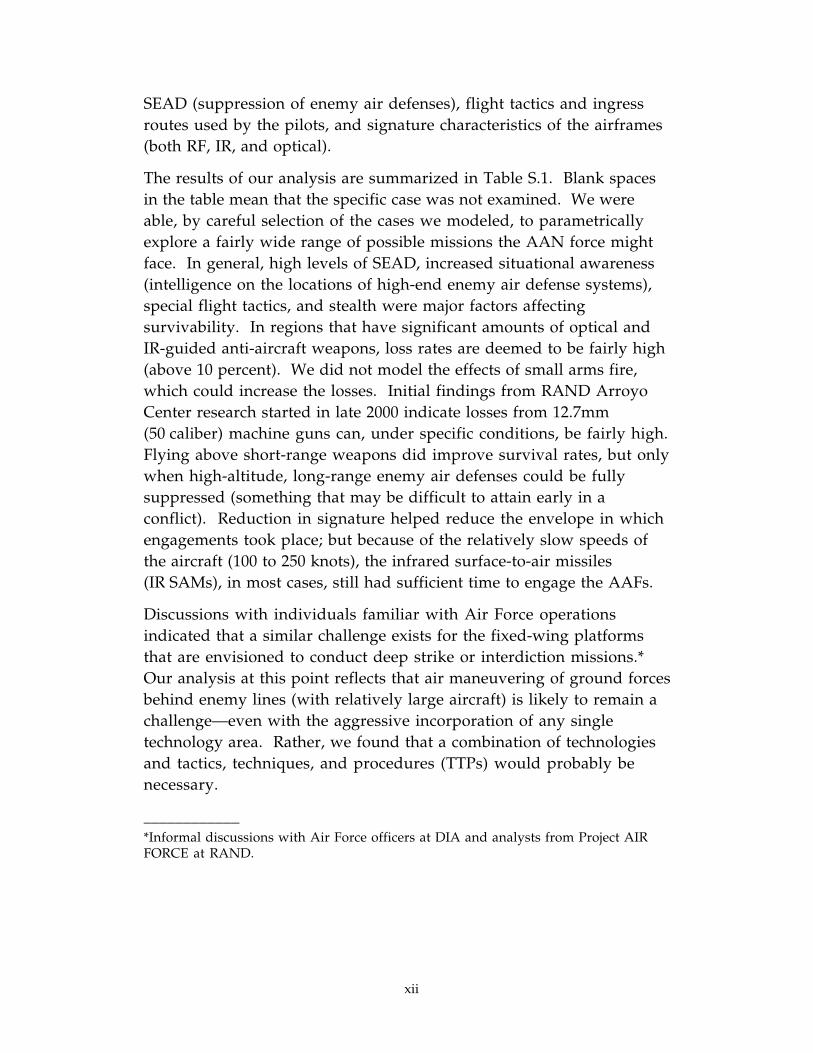
SEAD (suppression of enemy air defenses), flight tactics and ingressroutes used by the pilots, and signature characteristics of the airframes(both RF, IR, and optical).
The results of our analysis are summarized in Table S.1. Blank spacesin the table mean that the specific case was not examined. We wereable, by careful selection of the cases we modeled, to parametricallyexplore a fairly wide range of possible missions the AAN force mightface. In general, high levels of SEAD, increased situational awareness(intelligence on the locations of high-end enemy air defense systems),special flight tactics, and stealth were major factors affectingsurvivability. In regions that have significant amounts of optical andIR-guided anti-aircraft weapons, loss rates are deemed to be fairly high(above 10 percent). We did not model the effects of small arms fire,which could increase the losses. Initial findings from RAND ArroyoCenter research started in late 2000 indicate losses from 12.7mm(50 caliber) machine guns can, under specific conditions, be fairly high.Flying above short-range weapons did improve survival rates, but onlywhen high-altitude, long-range enemy air defenses could be fullysuppressed (something that may be difficult to attain early in aconflict). Reduction in signature helped reduce the envelope in whichengagements took place; but because of the relatively slow speeds ofthe aircraft (100 to 250 knots), the infrared surface-to-air missiles(IR SAMs), in most cases, still had sufficient time to engage the AAFs.
Discussions with individuals familiar with Air Force operationsindicated that a similar challenge exists for the fixed-wing platformsthat are envisioned to conduct deep strike or interdiction missions.*Our analysis at this point reflects that air maneuvering of ground forcesbehind enemy lines (with relatively large aircraft) is likely to remain achallenge—even with the aggressive incorporation of any singletechnology area. Rather, we found that a combination of technologiesand tactics, techniques, and procedures (TTPs) would probably benecessary.
____________*Informal discussions with Air Force officers at DIA and analysts from Project AIRFORCE at RAND.

xiii
Table S.1
Summary of Air Maneuver Survivability Results:Percent of AAN AAF Surviving the Mission
Parameters examined
Medium-level SA High-level SA
No SEAD MediumSEAD
High-levelSEAD No SEAD Medium
SEADHigh-level
SEAD
Flight pathdescription/creator
Basesig
LOsig
Basesig
LOsig
Basesig
LOsig
Basesig
LOsig
Basesig
LOsig
Basesig
LOsig
Baseline/RAND analyst 0% 0% 0% 25%
Low & slow/RAND analyst* 40% 57% 93% 98% 62% 79% 79% 88% 93% 100%
Low & fast/Navy pilot 19% 63% 56% 87% 56% 87%
Very low & slow/Army pilot 62% 87%
Medium altitude/Navy pilot 0% 100%
DEFINITIONS: Medium-level SA provides Intel on 50% of SAMs (type and location); high-levelprovides 100% Intel. No SEAD means all AD units active; medium SEAD means SA-12s, SA-17sremoved; high-level SEAD means SA-12s, SA-17s, SA-15s, and 2S6s removed.Base signature corresponds to AAF; LO signature corresponds to notional level of stealth.
*Over-water-only cases.
In addition to the technology and TTPs examined, other options mayhave important effects on mission success. Technologies that should beinvestigated include advanced infrared and RF countermeasures,optical dazzlers, and stealth technologies. Tactics such as unmannedinsertion of the combat vehicles, the use of decoys, and preemptiveSpecial Operations Forces (SOF) insertion of the combat crews toneutralize air-defended areas may also provide other solutions.
The results of this part of the study should not be interpreted as thefinal word on air-mech operations in enemy airspace, but as a first lookat a complex problem. We believe this research shows the magnitudeof the problem and provides important insights on potential solutionsets. Many of these insights are relevant for the Army’s currenttransformation efforts and should be used as a starting point for
xiv
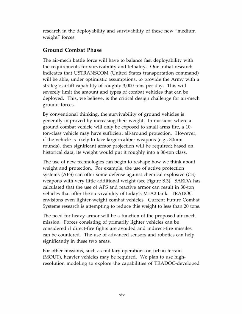
research in the deployability and survivability of these new “mediumweight” forces.
Ground Combat Phase
The air-mech battle force will have to balance fast deployability withthe requirements for survivability and lethality. Our initial researchindicates that USTRANSCOM (United States transportation command)will be able, under optimistic assumptions, to provide the Army with astrategic airlift capability of roughly 3,000 tons per day. This willseverely limit the amount and types of combat vehicles that can bedeployed. This, we believe, is the critical design challenge for air-mechground forces.
By conventional thinking, the survivability of ground vehicles isgenerally improved by increasing their weight. In missions where aground combat vehicle will only be exposed to small arms fire, a 10-ton-class vehicle may have sufficient all-around protection. However,if the vehicle is likely to face larger-caliber weapons (e.g., 30mmrounds), then significant armor projection will be required; based onhistorical data, its weight would put it roughly into a 30-ton class.
The use of new technologies can begin to reshape how we think aboutweight and protection. For example, the use of active protectionsystems (APS) can offer some defense against chemical explosive (CE)weapons with very little additional weight (see Figure S.3). SARDA hascalculated that the use of APS and reactive armor can result in 30-tonvehicles that offer the survivability of today’s M1A2 tank. TRADOCenvisions even lighter-weight combat vehicles. Current Future CombatSystems research is attempting to reduce this weight to less than 20 tons.
The need for heavy armor will be a function of the proposed air-mechmission. Forces consisting of primarily lighter vehicles can beconsidered if direct-fire fights are avoided and indirect-fire missilescan be countered. The use of advanced sensors and robotics can helpsignificantly in these two areas.
For other missions, such as military operations on urban terrain(MOUT), heavier vehicles may be required. We plan to use high-resolution modeling to explore the capabilities of TRADOC-developed

Lev
el o
fP
rote
ctio
n(F
ron
tal A
rc)
010
2030
4050
6070
80
Wei
gh
t (t
on
s)
Cu
rren
t U
S V
ehic
les
Up
gra
ded
wit
h A
PS
En
visi
on
ed b
y S
AR
DA
a
En
visi
on
ed b
y TR
AD
OC
b
140m
m K
EP
125m
m K
EP
LO
SA
T
Hel
lfir
e
TO
W II
HE
AT
RP
G/P
GM
M
45m
m c
ann
on
30m
m c
ann
on
Sm
all a
rms,
arti
llery
fra
g’s
M1A
2
M1A
1
M60
M48
M11
3
M2A
1
M2A
2
LA
V-2
5
An
ti-K
E
soft
kill
SL
ID
Car
rier
Fig
hte
r2-
leve
l har
d ki
ll
AR
V
AF
V
IFV
TK
2000
a: J
uly
199
8 S
AR
DA
bri
efin
gb
: 19
97 A
AN
Gam
e B
oo
k
xv
Figure S.3—Increased Protection Often Leads to SignificantlyGreater Vehicle Weight
xvi
air-mech forces, in offensive and defensive operations. Key to thisexploratory study will be the development of measures of effectiveness(MOEs). Given the nonlinear deployment of the air-mech forces, newMOEs will be needed. Initial research indicates that shock anddisruption will be MOEs as useful as attrition.
We note that the Army’s Objective Force goals are remarkablyconsistent with the TRADOC AAN air-mech forces’ goals.
INSIGHTS
This research suggests that a combination of technologies and tacticsare needed to perform the air-insertion portion of an air-mech mission.The quantity and quality of the enemy’s air defenses will determinewhat combinations are needed, and what level of success will occur.Long-range RF SAMs were found to be the principal threat to aircraft.Several sets of tactics and technologies can minimize the exposure ofthe aircraft to these SAMs. Given appropriate tactics and technologiesfor dealing with the RF SAM threat, we found that the limiting factorwill then be the amount of optically and IR-guided air defense systemsthe air-mech forces are exposed to. Cross-FLOT∗ missions, inparticular, were found to expose the aircraft to significant amounts ofanti-aircraft artillery (AAA) and IR SAMs and resulted in high losses.Critical for the success of this phase of the mission will, therefore, bethe development of technologies and tactics to deal with thisoptical/IR threat. We propose two approaches that have the potentialto minimize the AAA and IR SAM threats.
The air-mech battle force needs to be significantly lighter than currentforces. This is also true of the current Objective Force as envisioned byGeneral Shinseki. Because the survivability of combat vehicles hasbeen traditionally related to the amount of armor on the vehicle (i.e.,the heavier the vehicle, the more survivable), analysts will thus have tolook at a large set of lightweight survivability technologies. Inaddition, tactics, techniques, and procedures that can minimize theforce’s exposure to enemy direct fire need to be developed. We expectthat a combination of technologies and tactics will be required for the
____________∗FLOT is forward line of troops.

xvii
air-mech battle force or Objective Force to be successful on the futurebattlefield.
INSIGHTS FOR THE OBJECTIVE FORCE
The air-insertion analysis performed in this study provided baselineassessments on the quantities and types of air defenses an adversarywould need to limit the Army’s ability to conduct this mission.Although we used a conventional threat based on current “Russian”doctrine and technology, we have several initial findings andrecommendations for future research efforts that we believe arerelevant for Objective Force air-insertion operations in enemy-controlled battlespace.
One key finding was the limiting effect of optically guided anti-aircraftmunitions. Further research is needed to better quantify the magnitudeof this problem. And, given its severity, additional research iswarranted on technologies to counter this problem. One approach inparticular (stealth fixed/tilt-wing aircraft) was shown, for our specificscenario, to provide a viable solution to this problem if a securelanding site can be quickly established. This would require a newaircraft program start, an expensive solution in today’s limited defensebudgets. Another possible solution is active protection systems thatcan counter both optically guided missiles and AAA. Both approachesshould be investigated in future research efforts.
Another critical issue was the high level of RF SAM suppressionneeded for mission survivability. This may not be feasible with SEADalone, particularly if the aircraft land in enemy-controlled areas.Research on active RF countermeasures and new tactics will be acritical part of future efforts.
In this initial study we looked at only two sets of air-insertion tactics.Other tactics may have the potential to significantly raise theprobability of successful air insertion of the objective force, and shouldbe the subject of future efforts.
Lastly, we looked only at air defense and countermeasure systems thatare currently deployed in significant numbers. Laser-guided missiles,imaging IR missiles, and anti-helicopter mines are three examples of

xviii
serious AAN air vehicle threats we did not model, but these willprobably be available in the 2020 time frame. The modeling andassessment of advanced threats and countermeasures such as laser-based infrared countermeasures (IRCM) will be a critical part of futureanalytic efforts.
We presented initial research on the ground phase of the air-mechconcept, now superseded by the medium-weight force transformationeffort. The goals of this force are remarkably similar to those of theAAN air-mech concept: developing the most deployable (i.e., lightestpossible, most sustainable) force capable of performing decisivedefensive and offensive missions. Future research should, therefore,concentrate on assessing the new medium-weight force beingdeveloped by the Army, DARPA, and industry. Leveraging off ofprevious RAND, Army, and industry research and collaboration withArmy agencies, future research efforts will be able to model fightingvehicles of different weight classes. Using the emerging concepts, newTTPs, doctrine, and vehicle capabilities developed by the Army will bethe critical first step in the analysis needed for the design/selection ofthe new medium-weight combat force.

xix
ABBREVIATIONS
AAA Anti-Aircraft Artillery
AAF Advanced Airframe
AAN Army After Next
ADA Air Defense Artillery
AEF Air Expeditionary Force
AFV Advanced Fighting Vehicle
AGL Above Ground Level
APS Active Protection System
ARL Army Research Laboratory
ARO Army Research Office
ARV Advanced Reconnaissance Vehicle
ASP Acoustic Sensor Program
ATACMS Army Tactical Missile System
ATGM Anti-Tank Guided Munitions
AWACS Airborne Early Warning and Control System
BAT Brilliant Anti-Armor submunition
C2 Command and Control
C3 Command, Control, and Communications
CAGIS Cartographic Analysis and GeographicInformation System
CE Chemical Explosive
CHAMP CAGIS Helicopter Advanced Mission Planner
CONUS Continental United States
xx
DARPA Defense Advanced Research Projects Agency
DBSM Decibels per Square Meter
DCSDOC Deputy Chief of Staff for Doctrine
DFAD Digital Feature Attribute Data
DSB Defense Science Board
EFOG-M Enhanced Fiber Optic Guided Missile
FDC Fire Direction Center
FLOT Forward Line of Troops
IAD Integrated Air Defense
IFV Infantry Fighting Vehicle
IR Infrared
KEP Kinetic Energy Projectile
KM Kilometer
KTO Kuwaiti Theater of Operations
KTS Knots
LO Low Observable
LOS Line of Sight
MADAM Model to Assess Damage to Armor withMunitions
MANPADS Man-Portable Air Defense System
MOE Measure of Effectiveness
MRMC Medical Research Materiel Command
MSR Main Supply Route
NDRI National Defense Research Institute
ODS Operation Desert Storm

xxi
RCS Radar Cross-Section
RF Radio Frequency
RISTA Reconnaissance, Intelligence, Surveillance, andTarget Acquisition
RJARS RAND’s Jamming Aircraft and RadarSimulation
RPG Rocket Propelled Grenade
RTAM RAND’s Target Acquisition Model
SA Situational Awareness
SAM Surface to Air Missile
SARDA Secretary of the Army for Research,Development, and Acquisition
SEAD Suppression of Enemy Air Defenses
SEMINT Seamless Model Integration
SIRCM Suite of Integrated Infrared Countermeasures
SIRFC Suite of Integrated Radio FrequencyCountermeasures
SLID Supersonic Low Cost Interceptor
TARDEC Tank and Automotive Research Developmentand Engineering Center
TRAC TRADOC Analysis Center
TRADOC Training and Doctrine Command
UAV Unmanned Aerial Vehicle
1
Exploring Air-Mech and VerticalEnvelopment Concepts
and Technologies
This annotated briefing summarizes RAND research conducted insupport of the Army After Next (AAN) initiative. RAND supports theAAN effort in a number of different ways; this document onlyaddresses RAND’s research in the area of high-resolution simulation.The focus was on the AAN’s air-mechanized battle force concept.* Thisreport covers research done in 1998.
We note that the air-mechanized (air-mech) battle force design andemployment concept represented the work of the AAN study project inthe FY96–98 time frame and has no relationship to the current “air-mech” concepts proposed by BG (ret.) David Grange and others.†
The “battle force” was a notional design construct used by AAN toanalyze possible future organizational constructs without theconstraints of current unit paradigms. One of the concepts (air-mech)explored was the organic capability, within a battle force, to air__________
*1997’s effort involved a detailed analysis of the AAN light battle force concept. SeeJohn Matsumura et al., The Army After Next: Exploring New Concepts and Technologiesfor the Light Battle Force, Santa Monica, CA: RAND, DB-258-A, 1999.
†David Grange et al., Air-Mech-Strike: 3-Dimensional Phalanx; Full-Spectrum ManeuverWarfare to Dominate the 21st Century, Paducah, KY: Turner Publications, August 2000.

2
maneuver both troops and medium-weight combat systems at bothtactical and operational depths. U.S. Army Training and DoctrineCommand’s (TRADOC’s) Army Transformation Study, Wargaming,and Analysis effort has replaced the idea of organic operational airliftof systems with a more general-purpose capability for external liftassets (Army and/or joint) to enable operational maneuver byObjective Force units.
3
The objective of this project is to help the U.S. Army explore and assessnew operational concepts and technology options within the verticalenvelopment context (looking roughly 30 years out). In doing so, ourintention was to coordinate our research closely with both user anddeveloper communities. As a result, we could then integrateexplorations and assessments of future technologies within a validframework of operational concepts and vice versa.
Project Objective
• Explore and assess new operational conceptsand technology options for the verticalenvelopment concept
− Team with user and developer communities
− Integrate explorations of operationalconcepts
− Incorporate assessments of technology

4
The research issues that we were asked to address by the projectsponsors are listed above. Issue number 1 was the key item of focus.
Research Issues to Be Addressed(for Air-Mechanized Battle Force)
1. To what extent can survivability be achieved throughnew tactics, techniques, and procedures (TTPs) andnew technology in the areas of:mobility & agility, terrain masking, signaturemanagement & control, active protection, lightweightarmor, comprehensive situational understanding,deception, and indirect fires?
2. What are critical components and performanceattributes of the air-mech concept and mobility?
3. What are appropriate combinations of sensors andweapons for adequate lethality?

5
This document is organized into five sections. The first sectiondescribes our methodology and simulation models. The second sectiondescribes the scenario we used to examine vertical envelopment forceexcursions. The next two sections present our initial findings. The lastsection discusses our insights from this research and what our nextsteps will be.
Outline
• Methodology
• Scenario
• Air maneuver phase
• Ground combat phase
• Insights

6
Simulation Capability Integrates ManyModels Locally
Information dominance
Aircraft/air defenseinteractions
SEMINTDistributed model interface
RJARS – BLUE MAX II – CHAMP
CAGIS – DTED – DFAD
Digital terrainrepresentation
ASP
Acousticssensors
JANUS – MADAM
Force-on-forcecombat simulation
Smart munitions
C3model
Activeprotectionsystem
RTAM – NVEOD Model
Enhanced target acquisition
Maneuver & firepowerForce protection
A portion of our research was devoted to modification anddevelopment of high-resolution models capable of representing theperformance of advanced-technology vertical envelopment systems.The primary vertical envelopment system used for this study was alarge derivative of the V-22, capable of vertical take-off and landingwith an AAN combat vehicle as its payload. We started with ourexisting distributed simulation environment for modeling groundcombat, developed over the course of several years on other projects.The structure of this distributed environment is diagrammed above.
The RAND version of JANUS serves as the primary force-on-forcecombat effectiveness simulation and provides the overall battlefieldcontext, modeling as many as 1,500 individual systems on a side. Thecombination of the RAND Target Acquisition Model (RTAM) and theCartographic Analysis and Geographic Information System (CAGIS)allows us to represent, as needed, detailed detection/acquisitionphenomenology, including those associated with low-observablevehicles. RAND’s Jamming Aircraft and Radar Simulation (RJARS)provides a means to simulate the detection, tracking, flyout, and fusingof air defense missiles. The Model to Assess Damage to Armor withMunitions (MADAM) enables us to simulate the effects of smart

7
munitions, including such aspects as chaining logic, multiple hits, andunreliable submunitions, among others. The Acoustic Sensor Program(ASP) provides a detailed simulation of acoustic phenomenology forsuch systems as air-delivered acoustic sensors and wide-areamunitions. The Seamless Model Integration (SEMINT) allows all ofthese locally distributed simulations to communicate while running onseparate processors.

8
The air-mech concept consists of two distinct phases: the first is theinsertion of the battle force, the second is the actual ground combat.Both phases must be successfully completed for mission success. Theair-insertion phase represents a significant challenge to the Army.
(For a larger, full-color illustration of this scenario, see page 15.)
The use of advanced intelligence assets, aggressive suppression, anddestruction of enemy air defense artillery (ADA) will minimize but noteliminate the ADA threat. Athough the Marine V-22 standard operatingprocedure is to “fly where the enemy ain’t,” the Army does not alwayshave this option. The ability to transport significant amounts of combatpower through areas with some enemy air defense assets is, therefore, ahigh-payoff capability that could significantly increase the Army’sability to quickly deploy and conduct missions in adverseenvironments. It was for this reason that we concentrated our firstanalytic efforts on the air-insertion phase, and specifically the ability ofthe notional AAN Rotorcraft to deal with various levels of ADA.
Research Involves Analysis of Air and Ground Ops
CAGIS TERRAIN NORTH(OVER-SEA APPROACH)
CAGIS TERRAIN EAST(OVER-LAND APPROACH)
JANUS TERRAIN(GROUND COMBAT)
Ground combat phase will beconducted in JANUS with MADAM,helo flight planner, & RJARS
Air maneuver phase will beconducted in CAGIS with thehelo flight planner & RJARS.
1
2
3
SAMs
SAMs
Click to add title
CSSI I
IWI I
I I I
I I
SOF..
SOF..
I I
I
I
I I
I I
I I
I I IHQ
...
...
...
SOF..
CSSI I
CSSI I
200 Km
III
9
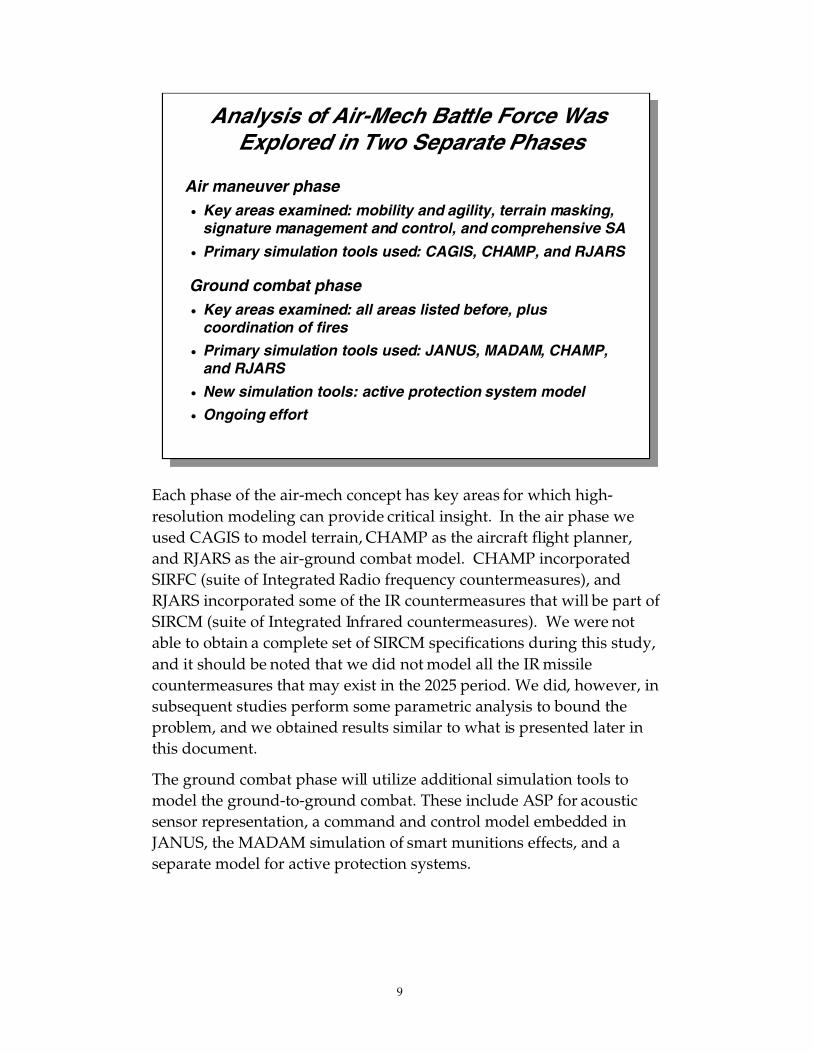
Each phase of the air-mech concept has key areas for which high-resolution modeling can provide critical insight. In the air phase weused CAGIS to model terrain, CHAMP as the aircraft flight planner,and RJARS as the air-ground combat model. CHAMP incorporatedSIRFC (suite of Integrated Radio frequency countermeasures), andRJARS incorporated some of the IR countermeasures that will be part ofSIRCM (suite of Integrated Infrared countermeasures). We were notable to obtain a complete set of SIRCM specifications during this study,and it should be noted that we did not model all the IR missilecountermeasures that may exist in the 2025 period. We did, however, insubsequent studies perform some parametric analysis to bound theproblem, and we obtained results similar to what is presented later inthis document.
The ground combat phase will utilize additional simulation tools tomodel the ground-to-ground combat. These include ASP for acousticsensor representation, a command and control model embedded inJANUS, the MADAM simulation of smart munitions effects, and aseparate model for active protection systems.
Analysis of Air-Mech Battle Force Was Explored in Two Separate Phases
Air maneuver phase• Key areas examined: mobility and agility, terrain masking,
signature management and control, and comprehensive SA
• Primary simulation tools used: CAGIS, CHAMP, and RJARS
Ground combat phase• Key areas examined: all areas listed before, plus
coordination of fires
• Primary simulation tools used: JANUS, MADAM, CHAMP,and RJARS
• New simulation tools: active protection system model
• Ongoing effort
10
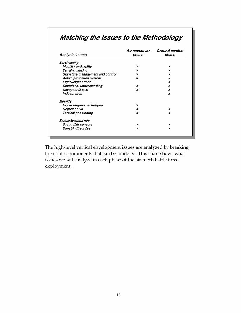
The high-level vertical envelopment issues are analyzed by breakingthem into components that can be modeled. This chart shows whatissues we will analyze in each phase of the air-mech battle forcedeployment.
Matching the Issues to the Methodology
SurvivabilityMobility and agilityTerrain maskingSignature management and controlActive protection systemLightweight armorSituational understandingDeception/SEADIndirect fires
MobilityIngress/egress techniquesDegree of SATactical positioning
Sensor/weapon mixGround/air sensorsDirect/indirect fire
Air maneuverphase
Ground combatphase
xxxx
xx
xxx
xx
xxxxxxxx
xx
xx
Analysis issues

11
Key to our analysis of vertical envelopment issues is the use of thesimulation tools. This chart shows how we plan to vary the modelparameters to explore the issues.
Incorporating Key Parameters in Simulation
SurvivabilityMobility and agilityTerrain maskingSignature management and control*Active protection system*Lightweight armorSituational understanding*Deception/SEADIndirect fires
MobilityIngress/egress techniquesDegree of SATactical positioning
Sensor/weapon mixGround/air sensorsDirect/indirect fire
* Partly addressed by SIRCM and SIRFC and modeled in simulation
Analysis issues
Adjust vehicle performance measuresVary vehicle movement pathsAdjust MRC/MRT, VIS/IR/RCS/dB, or PacqAdd new model to account for technologyIncrease/decrease Pk by aspectVary information displayed/usedAdd decoys/remove AD systemsIncorporate different levels of fire support
Vary maneuverability and speedModify knowledge of threatParametrically adjust time to emplace
Adjust numbers, coverage, capabilityExamine various combinations
Representative variations in simulation

12
In this section we first discuss how and why we selected the scenariofor this analysis. We then present the general scenario, describing theair insertion and ground force objectives and threat situation. Details ofthe air defense are presented in the air maneuver section, and groundforces are further described in the ground combat section.
Outline
• Methodology
• Scenario
• Air maneuver phase
• Ground combat phase
• Insights
13
Getting awayfrom “Desert
Storm revisited”
Getting awayfrom “Desert
Storm revisited”
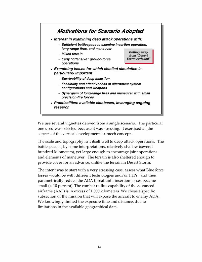
Motivations for Scenario Adopted• Interest in examining deep attack operations with:
− Sufficient battlespace to examine insertion operation,long-range fires, and maneuver
− Mixed terrain
− Early “offensive” ground-forceoperations
• Examining issues for which detailed simulation isparticularly important
− Survivability of deep insertion
− Feasibility and effectiveness of alternative systemconfigurations and weapons
− Synergism of long-range fires and maneuver with smallprecision-fire forces
• Practicalities: available databases, leveraging ongoingresearch
We use several vignettes derived from a single scenario. The particularone used was selected because it was stressing. It exercised all theaspects of the vertical envelopment air-mech concept.
The scale and topography lent itself well to deep attack operations. Thebattlespace is, by some interpretations, relatively shallow (severalhundred kilometers), yet large enough to encourage joint operationsand elements of maneuver. The terrain is also sheltered enough toprovide cover for an advance, unlike the terrain in Desert Storm.
The intent was to start with a very stressing case, assess what Blue forcelosses would be with different technologies and/or TTPs, and thenparametrically reduce the ADA threat until insertion losses becamesmall (< 10 percent). The combat radius capability of the advancedairframe (AAF) is in excess of 1,000 kilometers. We chose a specificsubsection of the mission that will expose the aircraft to enemy ADA.We knowingly limited the exposure time and distance, due tolimitations in the available geographical data.

14
The general strategy for how we might use joint forces in the verticalenvelopment period is shown in this chart. Critical to any verticalenvelopment analysis is the understanding of how the othercomponent-level forces will be participating in this mission. As we willdiscuss in the next two sections, the roles of the Air Force and Navy inthe area of suppression of enemy air defenses (SEAD) and joint fireswill be critical to the vertical envelopment battle force’s success.Similarly, these two services’ ability to transport the battle force into thetheater will be critical to the success of the vertical envelopmentconcept.
Objectives and Strategy Assumed for Analysis
• Friendly force objectives: quickly stop enemy advance,attack operational and strategic centers of gravity, anddisintegrate the enemy’s will to fight
• U.S. application of joint force
− Establish theater defenses, support allies with liaison teams,conduct SEAD, etc.
− Apply variety of long-range fires immediately
− Attack into enemy’s rear almost immediately to break hismomentum, destroy an operational center of gravity, his second-echelon operations

Gds
2020
X
XX XX
Supp
ort
Uni
ts
Supp
ort
Uni
ts
Supp
ort
Uni
ts
HQ
AD
A
I W
TAN
KIF
V’S
120
MO
RT
AR
C2V
M /
CM
ST
ING
RA
YIW
20
AD
AD
E
43 46 12 35 21 4 30 6
AD
A20
RM
RL
155
SP
AT
K H
EL
OT
RU
CK
S
12 12 12 36 300
CS
SI IIWI I
I I II I
SO
F..
SO
F..
I I
I
I
I II I
I I
I I I
HQ
...
...... SU
PP
LY C
ON
VO
Y
CS
SI IIWI I
I I I
I I
SO
F..
SO
F..
I I
I
I
I I
I I
I I
I I I
HQ
...
...... SU
PP
LY C
ON
VO
Y
100
km X
100
km
U.S
. Mis
sio
n:
Den
y E
nem
y’s
Ab
ility
to
Fo
rm“C
riti
cal M
ass”
to
Su
pp
ort
Ad
van
ce
15

16
GENERAL SCENARIO
An enemy has invaded a U.S. ally and U.S. forces are mobilized andpoised to enter the fray approximately one week after the onset ofhostilities. During the first week of battle, invading forces havemanaged to advance approximately 200 kilometers, overwhelminginitial allied forces’ attempts to prevent the invasion. Allied forces havetemporarily achieved a halt of the invading forces across a broadforward line of troops (FLOT), as depicted in the graphic on page 15.Gridline spacing is 50 kilometers. The invading forces, low on fuel andammunition, have assumed a hasty defensive posture waiting for theiroperational reserve to reach the FLOT and punch through the fragileallied defenses. The operational reserve is made up of a heavy, elitedivision advancing with one brigade up and two brigades back, trailedby sufficient logistics, in the form of fuel and ammunition, toreestablish momentum after reaching the FLOT. The enemycommander has secured his rear area with lighter infantry units alongthe northern, sea approach, protecting against an amphibious assaulton his flank, and has bolstered his rear area and main supply route(MSR) defenses with state-of-the-art air defenses ranging fromadvanced gun-missile combination (2S6), short-range, low-altitudesystems to long-range, high-altitude systems such as the SA-17 and SA-12, protecting against airborne and air-mobile assaults.
The vignette chosen for analysis pits a U.S. battle unit against the eliteheavy division. The battle unit’s mission is to disrupt, delay, or destroythis division. The battle unit will be air inserted into ambush positionsin front of the advancing division.
The battle unit selected for analysis in this scenario was one of six battleunits in the force under analysis by TRADOC. The other battle unitsattacked from the the flanks and the rear. Due to limited time andmodel constraints, we chose to model only one of the units being airinserted. The other battle units are an integral part of TRADOC’s AANconcept and must be modeled in any analysis of the ground combatphase.

17
We now discuss the analysis performed on the air maneuver phase ofthe air-mech concept.
Outline
• Methodology
• Scenario
• Air maneuver phase
• Ground combat phase
• Insights

18
A critical capability for the U.S. battle unit is that of self-deployability.To accomplish its assigned mission, the battle unit must fly into theenemy rear area to interdict the operational reserve by means ofdisruption, delay, or destruction. The focus of this phase of the analysiswas to examine the capability of the AAF to insert the battle unit’sground forces into the enemy rear area under different assumptionsand conditions.
Focus of Air Maneuver Phase
Perform initial study examining potential forsuccessful insertion of vertical envelopment
force in high-intensity threat environment

19
The methodology used to conduct this analysis can be described in thefollowing steps:
1. Decide where the U.S. battle unit must be inserted in order tosuccessfully accomplish its mission.
2. Establish a detailed (item-level) laydown for the enemy’sintegrated air defense (IAD) network in the theater’s area ofinterest defined above (air-to-air threats were not considered to bepart of the IAD for this effort). Use CAGIS to evaluate resultingradar coverage. Note enemy air was not modeled.
3. Establish varying levels of intelligence (Intel) to be presented to theaviators prior to mission planning. Present this information toaviators on an integrated CAGIS map display.
4. Establish varying flight profiles based on signature, SEAD andcountermeasures assumed. Load the associated data into RJARS.
5. Have experienced aviators fly flight paths for each of the AAFsusing the CHAMP flight planner.
6. Conduct parametric analysis by flying each of the sets of flightpaths in RJARS to determine aircraft survivability and criticalcomponents of the mission.
Air Maneuver Analysis Plan
• Employ early entry scenario with deep insertion “airmaneuver” phase
• Create challenging threat IADS environment(laydown, capabilities, and tactics)
• Use CAGIS, RJARS, and CHAMP to parametricallyexplore AAF survivability
• Present mission to experienced helicopter pilots
− Start with low Intel case first, move through tomedium and high Intel, along with necessary planning
− Vary flight profile, signature, level of SEAD,countermeasures

AIR
-ME
CH
BA
TT
LE U
NIT
INS
ER
TIO
N
AIR
-ME
CH
BA
TT
LE U
NIT
INS
ER
TIO
N
AF
V
36
AR
ES
18
AC
2V
22
AR
V
6
AF
SV
8
AF
SS
4
UA
V
2
ICO
N
C
AR
GO
# L
IFT
ER
S
ICO
NS
RE
PR
ES
EN
T L
Zs
FO
RL
IFT
ER
S O
N IN
SE
RT
ION
OF
BA
TT
LE
UN
IT.
CS
SI IIWI I
I I II I
SO
F..
SO
F..
I I
I
I
I I
I I
I I
I I I
HQ
...
......
20

21
The graphic on page 20 depicts the battle unit insertion. These landingzones were chosen assuming minimal subsequent movement byground vehicles once disembarked from AAFs.* Eighty-four aircraftare required to transport the battle force.
_____________
*Scenario assumed vertical insertion of the forces close to their planned fightingpositions. The landing sites were also selected to be in an area not covered by enemyair defense. The assumption that safe and tactically significant landing sites canalways be found may not always be true. This is a best-case scenario, and it wasselected to separate the ground combat issues from the air-insertion analysis effort.Other scenarios have the forces maneuvering to the battle sites after being inserted.

22
An Integrated Air Defense Network Is Oneof the Enemy’s Moderate-Cost
Highly Effective Combat Multipliers
SA-17
SA-12
SA-17
III
X
XX
XX
SA-12
SA-17
SA-17
SA-17
The quantity and quality of enemy air defenses can have a verysignificant impact on the viability of the air-mech (or other) verticalenvelopment concept. The Defense Intelligence Agency and theNational Ground Intelligence Center were consulted on worldwidetrends in air defense systems. Based on their very helpful input, RANDconstructed a hypothetical air defense system that would be coveringan advancing enemy army. The air defenses depicted in this scenarioare intended to represent a “high-end” opponent of the 2020 era.Today, the Russian army is capable of fielding the type of air defensesystem depicted in this research. In coming years, other armies may beable to employ similar integrated air defense systems.
The enemy air defenses are allocated by echelon. In this chart we showthe corps-level long-range, high-altitude defenses represented by theSA-12 and SA-17 batteries. It was assumed that the enemy corpsdepicted on the map (which is in charge of the enemy’s main effort;other forces are off-map to the south and west) would be accompaniedby two battalions (total of six batteries) of SA-12s and two battalions(also six batteries) of SA-17s. By the time this vignette takes place, weassume that each battalion has already lost one battery due to U.S. andallied SEAD.
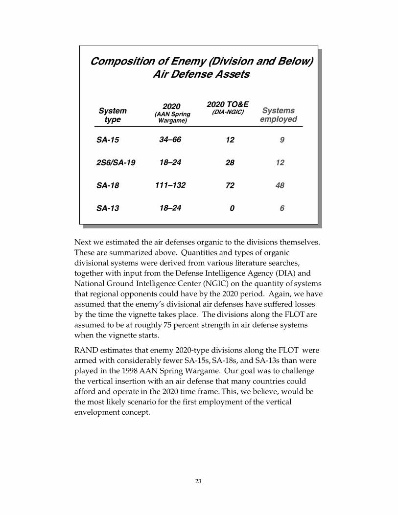
23
Next we estimated the air defenses organic to the divisions themselves.These are summarized above. Quantities and types of organicdivisional systems were derived from various literature searches,together with input from the Defense Intelligence Agency (DIA) andNational Ground Intelligence Center (NGIC) on the quantity of systemsthat regional opponents could have by the 2020 period. Again, we haveassumed that the enemy’s divisional air defenses have suffered lossesby the time the vignette takes place. The divisions along the FLOT areassumed to be at roughly 75 percent strength in air defense systemswhen the vignette starts.
RAND estimates that enemy 2020-type divisions along the FLOT werearmed with considerably fewer SA-15s, SA-18s, and SA-13s than wereplayed in the 1998 AAN Spring Wargame. Our goal was to challengethe vertical insertion with an air defense that many countries couldafford and operate in the 2020 time frame. This, we believe, would bethe most likely scenario for the first employment of the verticalenvelopment concept.
Composition of Enemy (Division and Below)Air Defense Assets
2020 TO&E(DIA-NGIC) Systems
employed
SA-15
2S6/SA-19
SA-18
SA-13
12
28
72
0
9
12
48
6
Systemtype
2020 (AAN SpringWargame)
34–66
18–24
111–132
18–24

Lo
cati
on
s o
f E
nem
y A
ir D
efen
se S
yste
ms
AA
A
SA
-13
SA
-15
Gro
un
d-B
ased
Ear
ly W
arni
ng
Rad
ar
Air
bo
rne
UA
V E
arly
War
nin
g R
adar
SA
-12
SA
-18
2S6
Gu
n/M
issi
le C
om
bin
atio
n
SA
-17
Key
1
2
3
24

25
Two tiers of enemy air defense were instituted in the scenario, picturedon page 24.
The lower-quality ADA units are along the coast. As the enemy forceadvanced into the territory of the U.S. ally, lower-quality units (truck-mounted infantry, for example) were deployed along the coast toprotect it against a flanking amphibious assault. These units haveconsiderably fewer air defense systems than the divisions along theFLOT. Anti-aircraft artillery (AAA) have been substituted for 2S6, andthere are far fewer SA-18 man-portable air defense systems(MANPADS) in the units in the north. Gridline spacing is 50kilometers.
The figure depicts the detailed, integrated air defense laydown createdin RJARS for this analysis. The defense is partitioned into threesections for analysis:
1. Upper left quadrangle: northern sea air approach
2. Lower right quadrangle: eastern cross-FLOT air approach
3. Lower west–central quadrangle: ground combat zone modeled inJANUS
Each of these areas was examined separately.
The upper right quadrangle (covered by the key in the figure) was notconsidered as an air approach for analysis because of the extremedistances that insertion aircraft would have to traverse, and because itwas assumed to be populated by air defenses of an adjoining enemyunit (not shown).

26
High-Altitude Enemy Air Defense Coverage
SA-15
SA-17
SA-12
Low-Altitude Enemy Air Defense Coverage
SA-18
AAA
2S6
Early warningradar
Low-Altitude Enemy Air Defense Coverage
SA-18
AAA
2S6
Early warningradar

27
The top figure on page 26 depicts the radar coverage provided bymedium- and high-altitude air defense radars. The fans drawnrepresent line-of-sight (LOS) weapons ranges for each of the three typesof radar-guided surface-to-air missiles (SAMs) included here. The LOSfans were calculated for altitudes in excess of 20,000 feet. The variousair defense radar fans are represented as follows:
Red: SA-15 radars
Green: SA-12 radars
Orange: SA-17 radars
Additionally, LOS fans for early-warning radars are represented on thischart as follows:
Blue: Airborne UAV early-warning radars
Magenta: Ground-based early-warning radars
The total coverage of the area by radio-frequency (RF) SAMs, at thisaltitude, will cause significant challenges for any aircraft. DIA andNGIC believe this will be standard coverage for many potentialregional adversaries in the AAN time frame.
Additional SEAD, and other radar countermeasures, will be requiredfor any vertical envelopment aircraft flying at this altitude. Taking outindividual radars should have limited impact, because of the integratedarchitecture used by the enemy. This points out the need for new TTPsbased on the increased levels of situational awareness available in theAAN time frame.
The bottom figure on page 26 depicts the weapons coverage of theenemy’s low-altitude systems, specifically against a nonstealthy aircraftoperating at 100 feet above ground level. Note that there are a largenumber of enemy systems capable of engaging aircraft at this altitude.Small white circles represent pairs of 30mm anti-aircraft guns, yelloware SA-18 MANPADS and 2S6 self-propelled gun/missile systems, andpink are SA-13. Note how the range fans of SA-12, 15, and 17 are allmuch smaller than that shown in the previous diagram (medium-/high-altitude coverage). Not shown on this diagram is the threat

28
posed by weapons such as tank main guns, wire-guided missiles, andheavy machine guns, all of which are capable of engaging (undercertain conditions) low-altitude aircraft.
The figure shows that the enemy ADA does not have completecoverage of the area of operation. There are areas that have radarcoverage but no weapons capable of engaging the aircraft.

29
To better understand the severity of the ADA problem for verticalenvelopment, we now present a short description of each of thesystems. All the data presented are from Jane’s 1998–1999 land-basedair defence book. These are the advertised capabilities of the systems.Real capabilities in 2020–2030 may be different. Vertical envelopmentconcepts should, as a starting point, be able to deal with current high-end ADA systems.
The SA-12 has the ability to acquire and engage targets at 100-mile-plusranges. Like many high-end systems, it has a very capable radar andmissiles with high flyout speed and good altitude capabilities. Thisdoes not mean that the SA-12 is invincible, but considerable researchand development of equipment and concepts for dealing with thissystem will be needed for the air-mech concept to be successful.
SA-12 Is a Tactical SAM Which Can Engage Both Aircraft and Missiles
SA-12 characteristics
• Surveillance radar range:250 km
• Sector scanning radar range:175 km
• Missile guidance radar range:150 km
• Target radar cross section:2 sq. m
• Missile max. range: 100 km(Gladiator) 200+ km (Giant)
• Missile min. range: 6 km
SOURCE: Jane’s 1998–1999 Land-Based Air Defence
Surveillanceradar
TELAR

30
The SA-17 fills the gap between short- and long-range ADA systems. Itis readily transportable and will pose tactical problems for verticalenvelopment. Like the SA-12, technical and operational techniquesneed to be developed to deal with this threat.
The SA-15 is an extremely mobile short-range ADA system. Its radarhas shorter detection ranges than the SA-17’s. The large number ofSA-15s in the battlefield will, however, challenge the Blue force aircraftflying in enemy-controlled airspace.
SA-17s and SA-15s Are Primarily Designed to Defend Against Close Air Support
SA-17 characteristics
• 160 km detection range
• 120 km acquisition range
• Effective against targets at15 to 25,000 m altitudes
• Missile range: 50 km
SA-15 characteristics
• 25 km Doppler radar
• Effective against targets at10 to 6,000 m altitudes
• Missile range: 1.5 to 12 km
SOURCE: Jane’s 1998–1999 Land-Based Air Defence
SA-17
SA-15

31
Lastly we present data on short-range ADA systems. Of critical concernis the ability of these systems to operate in the nonemitting mode, i.e.,using thermal sensors or optically guided. Along with small arms fireand tank rounds, these systems represent the limiting ADA case whenRF systems have been suppressed.
Infrared and optical countermeasures need to be developed to dealwith these systems.
Low-Altitude Systems Tend to HaveSmaller Engagement Envelopes
2S6 tracked AD unit• 30mm (4) radar directed
• SA-19 missile
SA-18 MANPAD• Effective against targets at 10
to 3,500 m altitudes
• Missile range: 0.5 to 5.2 km
AAA• 30mm optically directed
• 3–4 km engagement range
SOURCE: Jane’s 1998–1999 Land-Based Air Defence
2S6
SA-18
AAA

32
This figure shows the difficulty of flying above long-range SAMsystems. Effective suppression of SA-12s and SA-17s will be requiredfor Blue force aircraft to operate at medium altitudes in thisenvironment.
High-End SAMs Have Comparatively Larger Envelopes (both Altitude and Range)
Altitude (km) 6
Range (km)0 50 100
25
SA-17 SA-12A
3.5SA-15
10
2S6SA-18
SAM engagement space
SOURCE: Jane’s 1998–1999 Land-Based Air Defence

33
This chart demonstrates one of the weaknesses of the medium- andhigh-altitude SAMs. Jane’s lists the SA-12’s minimum engagementaltitude as 200 meters. Close-in, very-low-flying aircraft are relativelyunaffected by these SAM systems. The low-flying aircraft will,however, be exposed to low-altitude SAMs, such as the SA-15 andSA-18. Using countermeasures and flight tactics can potentiallyminimize losses from these systems. Current versions of the SA-10d canengage helicopters at a 10-meter altitude (Jane’s). We therefore assumethe SA-12 will be developed with lower engagement altitudecapabilities by 2020 in our model.
However, High-End SAMs Have CriticalLimitations as Well
Alt
itu
de
(m)
Range (km)0 5 15
SA- 151,000
10
100
500SA-17
SA-12
SA-18
SA-19
Low-altitude engagement envelopes
SOURCE: Jane’s 1998–1999 Land-Based Air Defence
34
Key Assumptions Made for Our Analysis
• Tilt-rotor data is valid– Relatively large airframe (both fuselage and rotors)
– RCS and IR signature levels roughly twice that of V-22
• Mission occurs during daytime, good weather
• Flight profiles were created by RAND analysts andNavy and Army aviators
• 84 aircraft flown, half from east and half from north (overwater), in tight formation in trail
• Enemy AD assumed to operate in autonomous C2 mode(minimal integration)
• MANPADS and AAA positions not known prior to mission
• Tanks and small arms fire not modeled
• IRCM effectiveness estimated from current IRCM and CCMtechnology trends
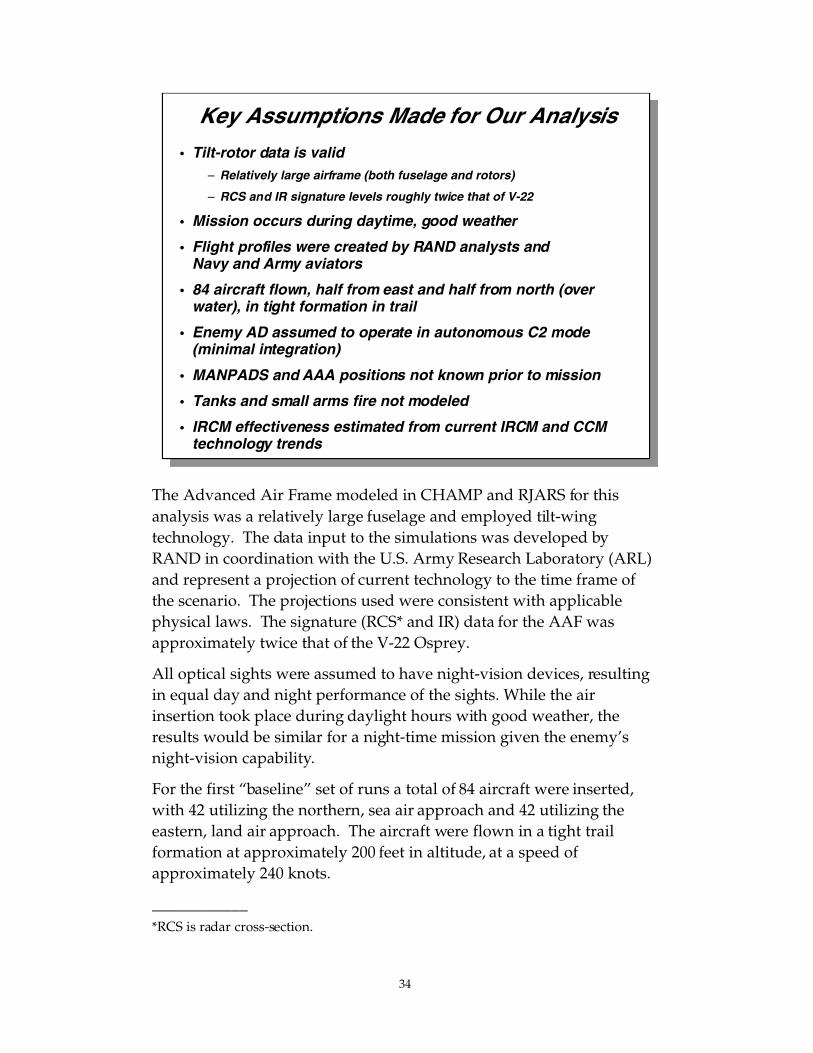
The Advanced Air Frame modeled in CHAMP and RJARS for thisanalysis was a relatively large fuselage and employed tilt-wingtechnology. The data input to the simulations was developed byRAND in coordination with the U.S. Army Research Laboratory (ARL)and represent a projection of current technology to the time frame ofthe scenario. The projections used were consistent with applicablephysical laws. The signature (RCS* and IR) data for the AAF wasapproximately twice that of the V-22 Osprey.
All optical sights were assumed to have night-vision devices, resultingin equal day and night performance of the sights. While the airinsertion took place during daylight hours with good weather, theresults would be similar for a night-time mission given the enemy’snight-vision capability.
For the first “baseline” set of runs a total of 84 aircraft were inserted,with 42 utilizing the northern, sea air approach and 42 utilizing theeastern, land air approach. The aircraft were flown in a tight trailformation at approximately 200 feet in altitude, at a speed ofapproximately 240 knots.
____________*RCS is radar cross-section.

35
The air defense network radars and C2 network provided earlywarning to individual air defense assets operating in a weaponsfree–autonomous mode.
For the high-situational-awareness case, aviators were given locationsof all threats with the exception of MANPADS (SA-18s) and AAA.
Neither tank main guns nor small arms fire were modeled as threats.
IR countermeasure effectiveness was projected to the scenario timeframe based on current technology trends. Counter-countermeasureswere also incorporated in the missiles.

36
The chart illustrates the relative signatures of the modeled AAF whencompared to several other types of aircraft.* The RCS comparisons arelogarithmic (DBSM), while the thermal are linear (degrees centigrade).
Discussions with the Army aerodynamics engineers researching verticalenvelopment tilt-rotor signature issues led to the estimate that the verticalenvelopment tilt-rotor transports’ optical, IR, and RF signatures could bemodeled as twice that of a multi-engine transport plane.
Transport aircraft are generally not designed to be stealthy. To explore thepotential effects of stealth, we postulated that a prop-driven transportcould have the signature characteristics of a low-observable (LO) aircraft.The LO aircraft RF and IR signatures are very low compared to thenonstealth aircraft, and do not appear on the same scale in this graph.
_____________
*Radar data from Fred E. Nathanson, Radar Design Principles, New York: McGraw-Hill,1969, and Rebecca Grant, The Radar Game, Arlington, VA: IRIS, 1998. Thermal data fromRichard D. Hudson, Jr., Infrared System Engineering, New York: John Wiley and Sons,1969.
Base Vertical Envelopment Airframe HasRelatively High RCS and IR Signature
Tra
nsp
ort
VE
-AA
F
Att
ack
Bo
mb
er
Fig
hte
r
Ste
alth
Zo
ne
VE
-AA
F
RCS comparison IR comparison
Ste
alth
Zo
ne
Tra
nsp
ort

37
The analysis entailed varying several key parameters expected to havea significant impact on mission outcome.
Each set of aviators generated flight paths based on a given amount ofsituational awareness (SA) and a specific set of flight tactics. We thenvaried the level of SEAD and the aircraft’s IR and RF signatures in theRJARS model. Each case was run between 10 and 20 times. RJARSresults for overall kills were the same for each case, though in severalcases the number killed by a specific weapon system changed (forexample, one run might have 6 kills by AAA and 7 by SA-18s, the nextrun might have 5 kills by AAA and 8 by SA-18s).
Key Parameters Explored in Air Maneuver Phase of Analysis
• Flight paths: different operators
− Ingress/egress locations and formations forairlifters
− Airlifter mobility performance attributes (speedand altitude)
• Level of situational awareness provided
• Level of enemy air defenses active in simulation(due to SEAD)
• Airlifter thermal and visual signatures (parametricreduction in simulation)

38
The aviators who flew the flight paths were a mixed group of RANDanalysts and Navy and Army aviators. The run sequence was based onthe availability of aviators. The set of flight paths generated enabledRAND to explore a large range of parameters, as discussed in the nextchart.
Variety of Flight Path Locations and Profiles Were Considered in Air Maneuver Analysis
Flight path Path profile Path creator
Baseline 200 ft AGL/240 kts RAND analyst
Low & slow 50 ft AGL/60 kts RAND analyst
Low & fast 70 ft AGL/200 kts Navy helo pilot
Very low & slow 20 ft AGL/100 kts Army helo pilot
Medium altitude 20,000 ft AGL/330 kts Navy pilot

39
The chart shows which excursions were examined during the conductof the analysis. Where possible, we attempted to test either end of theenvelope for each parameter first, before delving into the middleground where arriving at a point solution would be difficult at best.Rather, we were trying to draw more general conclusions about whichparameters dominated the outcomes. For example, for the medium-level SA excursions, we examined first the baseline and LO signaturecases without SEAD and with a high level of SEAD, and determinedfrom those outcomes that the medium-level SEAD cases could offer noadded value to the analysis.
Similarly, in the high-level SA excursions, we examined the baselinesignature cases without SEAD and medium-level SEAD first, and fromthese results determined that the high-level SEAD case could provideno additional value to the analysis.
It is important to note this is a parametric analysis. We do not proposethat the Army consider missions over well-defended enemy territorywith insufficient situational awareness and no SEAD. The analysis,however, was intended to give insights on what levels of SA, SEAD,and stealth are needed to conduct a successful air insertion mission.These aspects are discussed in the next slide.
Excursions Examined in Simulation
Medium-level SAParameters examined
High-level SA
No SEAD
MediumSEAD
High-levelSEAD
No SEAD
MediumSEAD
High-levelSEAD
Flight pathdescription/creator Base
sigBasesig
Basesig
Basesig
Basesig
Basesig
LOsig
LOsig
LOsig
LOsig
LOsig
LOsig
Baseline/RAND analyst
Low & slow/RAND analyst
Low & fast/Navy pilot
Very low & slow/Army pilot
Medium altitude/Navy pilot
DEFINITIONS: Medium-level SA provides Intel on 50% of SAMs (type and location); high-level provides100% Intel. No SEAD means all AD units active; medium SEAD means SA-12s, SA-17s removed; high-level SEAD means SA-12s, SA-17s, SA-15s, and 2S6s removed. Base signature corresponds to AAF;LO signature corresponds to the level of a notional low-observable helicopter.Blank space means specific case was not examined.
√ √
√ √ √
√√
√ √
√
√√√√√√√
√√
√√√√√

40
A total of 24 excursions were examined during the course of the analysis. Acursory examination of the results yields the following general conclusions:
1. Greater SA significantly improves mission survivability.
2. SEAD is effective when used with increased SA and/or stealth.
3. Stealth by itself improves survivability.
4. Stealth, SA, and SEAD by themselves do not lead to acceptablemission survivability rates.
5. Combinations of stealth, SA, SEAD, and flight tactics can result insuccessful missions.
It is important to note again that we are not suggesting Army aviatorswould or should conduct any of the high-loss missions. The analysis they wouldconduct in the mission-planning phase would identify the high loss rate and themission would, in most cases, not be flown, or significantly lower-loss flightpaths would be proposed.
None of the observations are counterintuitive, and the results do demonstrate aconsistency across all of the excursions. Further examination of the excursions,grouped by flight profile, was warranted. These resultsare shown in the following charts, beginning with a description of the flightprofiles for the first group (RAND analyst).
Summary of Results: Percent of Vertical Envelopment AAFs Surviving Mission
Medium-level SAParameters examined
High-level SA
No SEAD
MediumSEAD
High-levelSEAD
No SEAD
MediumSEAD
High-levelSEAD
Flight pathdescription/creator Base
sigBasesig
Basesig
Basesig
Basesig
Basesig
LOsig
LOsig
LOsig
LOsig
LOsig
LOsig
Baseline/RAND analyst
Low & slow/RAND analyst*
Low & fast/Navy pilot
Very low & slow/Army pilot
Medium altitude/Navy pilot
DEFINITIONS: Medium-level SA provides Intel on 50% of SAMs (type and location); high-level provides100% Intel. No SEAD means all AD units active; medium SEAD means SA-12s, SA-17s removed; high-level SEAD means SA-12s, SA-17s, SA-15s, and 2S6s removed.Base signature corresponds to AAF; LO signature corresponds to notional level of stealth.
0% 0% 0% 25%
40% 57% 93% 98% 62% 79% 79% 88% 93% 100%
19% 63% 56% 87% 56% 87%
0% 100%
87%62%
* Over-water-only cases.

41
Locations of Baseline Paths (RAND Analyst)
CSSI I
IWI I
I I II I
SOF..
SOF..
I I
I
I
I I
I I
I I
I I IHQ
...
......
AIR-MECHBATTLE UNIT
INSERTION
AIR-MECHBATTLE UNIT
INSERTION
AFV 36ARES 18
AC2V 22ARV 6AFSV 8
AFSS 4UAV 2
ICON CARGO # LIFTERS
ICONS REPRESENT LZs FORLIFTERS ON INSERTION OFBATTLE UNIT.
Low & Fast Paths (Navy Pilot)
ARROYO CENTER## // ::
R
For Official Use Only
For Official Use Only
Low & Fast Paths (Navy Pilot)
ARROYO CENTER## // ::
R
For Official Use Only
For Official Use Only

42
The top image on page 41 depicts the baseline flight paths flown byRAND analysts. The flight paths were developed based on the groundforce (battle unit) maneuver plan (insert).
Each flight path depicted in red represents paths for six advancedairframes ingressing in a tight (~50 meter interval) trail formation.
All the airframes are flown in simultaneously on each approach route.

43
An examination of the attrition of the airframes over time, and by airdefense system, reveals that the SA-12 is the most dangerous threat tothe airframes, followed closely by the 2S6 and the SA-15.
The two approaches led to the aircraft being exposed to different ADAsystems. The aircraft flying in from the ocean were well within therange of an SA-12 and several SA-15s prior to landfall. Roughly 90percent of the aircraft were destroyed before they traveled 10kilometers in from the coast. SA-15s killed the rest as they progressedinland. The aircraft flying east across the FLOT were later shot down bya combination of 2S6s, SA-15s, SA-17s, and SA-18s. The 2S6s killedroughly half of the vertical envelopment tilt-rotor transports flyingcross-FLOT.
In Worst-Case Situation (No SEAD, Limited Intel, & No CM), No Aircraft Survive
0
10
20
30
40
50
60
70
80
90
Total
SA-122S6SA-15SA-18SA-17AAA
Air-craftlosses
0 3 6 9 12 15 18 21 24
Time (min.)
Flight path at ~200 ft and ~240 kts

44
Running the baseline case with Comanche (indicated by “reducedsignature” in the chart) did not change overall mission survivability. Thiswas due to the SAM radars still being able to pick up the Comanche. Thetarget acquisition ranges were primarily limited by the terrain and not theradar signature of the aircraft. In both cases (tilt-rotors and Comanche), RFSAM kills occurred at ranges significantly less than the RF missiles’maximum ranges, due to the low altitude at which the aircraft were flying.
Increasing the amount of SEAD did not change overall missionsurvivability. The tilt-rotors did, however, survive for a longer period.Again, we used a best-case scenario (a Comanche-like aircraft) to boundthe problem. In this case, SEAD was able to take out all SA-12s, 15s, and17s. While this is not realistic for the entire theater of operations, it may bepossible to clear several flight corridors. From an aviation tacticsstandpoint, all known SAM sites along the flight path would have to besuppressed to make the mission a “go.” We note that even in this case,mission success is not guaranteed. Additional tactics and technology areneeded.
Combining aggressive SEAD and stealthy aircraft enabled some aircraft tosurvive the mission. While the attrition rate was high, the concept of usingmultiple survivable enhancement techniques clearly had merit.
Reducing Signature Yielded Benefit in Conjunction with SEAD
Air-craftlosses
Time (min.)
0
10
20
30
40
50
60
70
80
90
0 10 20 30 40 50 60 70
Reduced signature alone
Base signature with SEAD(No SA-12s, 17s, 15s)
Reduced signature with SEAD
Base case
Flight path at ~200 ft and ~240 kts

45
When we examined the outcomes of excursions grouped by various SAlevels, we noted that increased SA reduced the effectiveness of theemitting SAMs. In this case we examined only the group of aircraftflying in from the ocean. The pilot was instructed to fly around orunder all RF SAM sites that appeared on the flight planning aid(CHAMP).
The limited aerodynamics of the tilt-rotor led to some SA-12 kills, evenwhen the pilot knew where all the SA-12s were. Two SA-12 missile sitescould not be totally avoided by the tilt-rotors. The SA-12’s targetacquisition radar can detect a two-square-meter aircraft at over 250kilometers. SA-12 missiles can engage targets at 100 kilometers.
It is therefore not surprising that over a 250-kilometer path traversingenemy-held terrain, surviving SA-12s have multiple opportunities toengage the vertical envelopment tilt-rotors.
Improved Situational AwarenessIncreases Mission Survivability
Losses of aircraft
Knowledge of emitting SAMs
Flight path at ~50 ft and ~60 kts
0
5
10
15
20
25
30
35
40
45
5 0% 100%
SA-18SA-15-SA-12

46
Improved Intelligence, SEAD, Stealth, and Low-Altitude Paths Enhance Mission Survivability*
SA-12 6 0 0 0
SA-17 0 0 0 0
SA-15 3 5 0 0
SA-18 7 4 5 0
2S6 0 0 0 0
AAA 0 0 0 0
Total 16 9 5 0
*42 tilt-rotors flying in from the ocean
AD System No SEAD No SA-12, 17No SA-12,
15, 17No SA-12,
15, 17, Stealth
Blue Aircraft Lost
The next series of runs examined the effects of variable levels of SEAD.When the SA-12s, 15s, and 17s are suppressed, mission survivability issignificantly increased. The SA-12 and SA-17 are not easily jammed andwill, therefore, require aggressive SEAD. SA-15s can potentially bejammed, but enemy tactics and improved versions of the SA-15 couldmake jamming of the missile more difficult. A jammer can also be usedby the enemy as a beacon for RF home-on-jam missiles and/orimproved SA for optically guided ADA such as AAA and IR SAMs.Other ADA assets such as the 2S6 will switch to the AAA mode whenjammed. There were very few non-RF ADA systems defending thecoastline (this was purposely designed), and as the table shows of thesesystems, only the SA-18s successfully engaged the vertical envelopmenttilt-rotor force.
Use of stealth further increases mission survivability. The lower IRsignature of the aircraft led to no SA-18 losses. The use of very goodsituational awareness, effective SEAD, and stealthy aircraft makes thistype of mission look feasible. The main challenge would be to locatethe majority of enemy active and passive air defense systems as themission was being planned, and then get continuous real-time updateswhile the aircraft are in flight.

47
Two problems were noted in this approach. First, the flight speed wasvery slow, less than 60 knots. The vertical envelopment ground vehiclescould likely drive to the landing site in a comparable amount of time.Second, the ADA environment was relatively free of optical ADAsystems, not expected in a mission flying over a front-line enemydivision (cross-FLOT).
One possible tactic is to fly fast and minimize the exposure time toenemy ADA. We modeled this tactic for both the ocean approach andthe cross-FLOT mission. (See bottom image on page 41.)

48
The cross-FLOT mission was successful in avoiding SA-12s, SA-15s,and 2S6s due to good situational awareness of the location of thesesystems. The large number of SA-18s and AAA, however, limitedmission survivability. Stealth (reduced optical and IR signatures)significantly reduced the number of aircraft atrited by these systems. A20 percent attrition rate, however, is unacceptable for most verticalenvelopment missions. IR jammers that are effective against SA-18could reduce the attrition further, potentially to acceptable levels. Smallarms fire as well as tanks and BMPs, however, were not included inthis model and could significantly raise the number of losses.
Tactics and technologies for dealing with the optical and IR air defensethreats need to be developed for the vertical envelopment air-mechconcept to be viable.
Cross-FLOT Mission* Survivability with Low Altitude, SEAD, and Stealth Is Low
No SA-12, 17AD system No SEAD No SA-12, 17 and Stealth
SA-12 0 0 0
SA-17 16 0 0
SA-15 0 0 0
SA-18 15 14 7
2S6 0 0 0
AAA 11 14 1
Total A/C lost 42 28 8
*42 tilt-rotors flying cross-FLOT

49
Very Low & Slow Paths (Army Pilots)
ARROYO CENTER## // ::
R
For Official Use Only
For Official Use Only
Medium Altitude Path (Navy Pilot)Medium Altitude Path (Navy Pilot)

50
The missions shown up to this point were flown by non-Army aviators.TRADOC was asked and subsequently provided Army aviators todetermine whether mission survivability could be increased by theappropriate use of TTPs.
Paths, as shown in the top figure on page 49, started out with 42 aircraftpunching through one point along the coast and 42 aircraft punchingthrough one point of the FLOT. After the initial ADA penetration eachgroup of 42 split into three groups of 14. Paths were similar topreviously presented cases (exceptions to this were the 20-foot AGLand 100-knot speed versus the previous case’s 240-knot, 70-foot AGL).Paths from the ocean punch through at the SA-17 site, which wasdestroyed before the AAFs flew into the area. Cross-FLOT paths wentthrough the city/town slightly in front of the FLOT, and between SA-15s on either side of the town.

51
The aviators from U.S. Army Aviation School and Centers developedTTPs based on very specific assumptions. They included significant SA,SEAD, and other countermeasures, including diversionary activitydesigned to confuse and saturate the enemy’s IAD network.
Army Aviators’ Vertical Envelopment Assumptions and TTPs
• Extensive reconnaissance prior to mission.
• All emitters’ positions known.
• Some fraction of nonemitter ADA assets known.
• Some fraction of enemy ADA can move during insertion mission.
• SEAD of certain critical SAM sites and airborne radar platforms.
• Mission flown with some vertical envelopment tilt-rotor attack aircraft.
• Real-time intelligence given to attack aircraft.
• Active radars and C2 sites will be suppressed during mission.
• Aircraft would fly at night/dusk to limit effectiveness of optically guided ADA.
• All aircraft make maximum use of SIRFC/SIRCM.
• Fixed-wing activity will diffuse the focus of threat ADA.
• Air Force and Navy will be flying tactical and/or operational missions during verticalenvelopment insertion.
• Flight paths will be 20 feet above ground and 100 knots over suspected RF SAMcovered/engagement areas.
• Vertical envelopment tilt-rotors will fly in groups of 14 in a tactical trail formationwith a 50-meter separation.

52
The results of the excursions employing the U.S. Army AviationSchool’s TTPs were found to be comparable to cases already flown andexamined (specifically those cases with high SA, high SEAD, andstealth). Again the limiting factors were the optical and IR air defensethreats. Even at dusk these systems are effective, particularly since theaircraft flew within a few hundred meters of several AAA and SA-18sites.
One method of countering the effects of low-altitude air defensesystems is to fly above their engagement envelopes. These paths wereflown by a Navy pilot and were above the range of AAA, MANPADS,2S6s, and SA-15s. (See the bottom image on page 49.)
Aviation Schools’ TTPs Did Not Significantly Change Mission Survivability Levels
Ocean Cross-FLOTAD system Ocean Cross-FLOT & Stealth & Stealth
SA-12 0 0 0 0
SA-17 0 0 0 0
SA-15 0 0 0 0
SA-18 10 11 5 4
2S6 0 0 0 0
AAA 2 9 0 2
Total A/C lost 12 20 5 6
*42 tilt-rotors per mission; flight path at 100 knots, 20-foot AGL over land
Mission
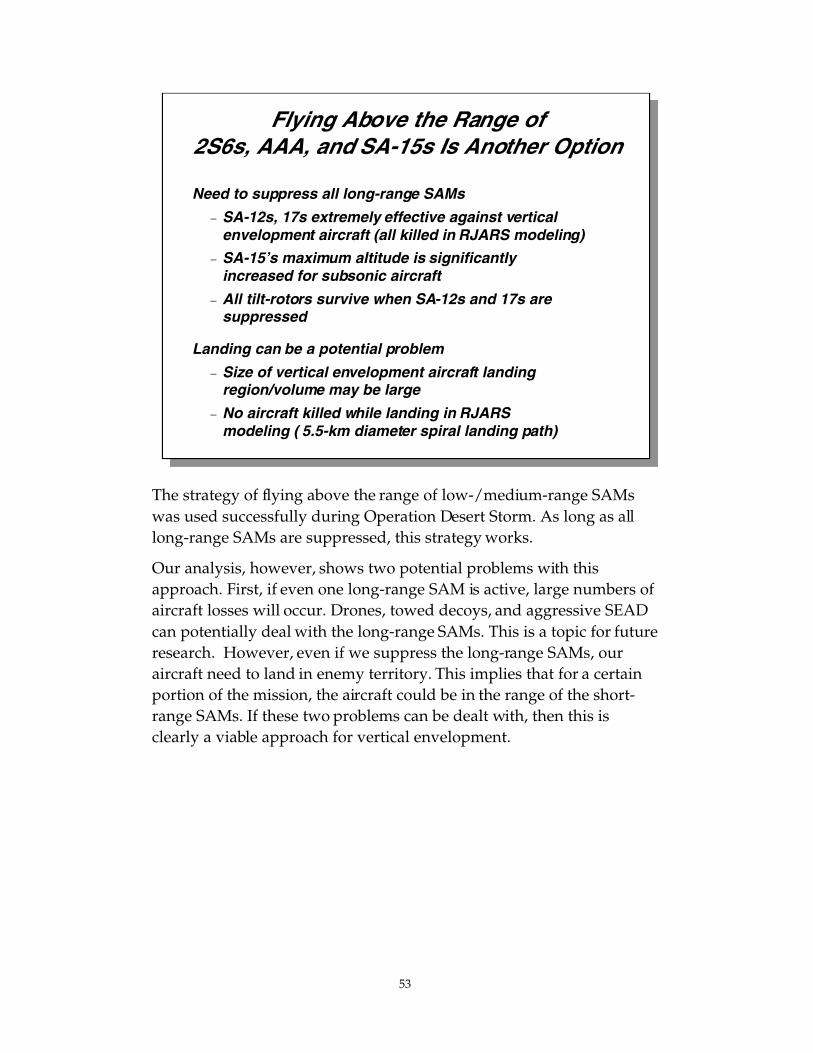
53
The strategy of flying above the range of low-/medium-range SAMswas used successfully during Operation Desert Storm. As long as alllong-range SAMs are suppressed, this strategy works.
Our analysis, however, shows two potential problems with thisapproach. First, if even one long-range SAM is active, large numbers ofaircraft losses will occur. Drones, towed decoys, and aggressive SEADcan potentially deal with the long-range SAMs. This is a topic for futureresearch. However, even if we suppress the long-range SAMs, ouraircraft need to land in enemy territory. This implies that for a certainportion of the mission, the aircraft could be in the range of the short-range SAMs. If these two problems can be dealt with, then this isclearly a viable approach for vertical envelopment.
Flying Above the Range of2S6s, AAA, and SA-15s Is Another Option
Need to suppress all long-range SAMs
− SA-12s, 17s extremely effective against verticalenvelopment aircraft (all killed in RJARS modeling)
− SA-15’s maximum altitude is significantly increased for subsonic aircraft
− All tilt-rotors survive when SA-12s and 17s are suppressed
Landing can be a potential problem
− Size of vertical envelopment aircraft landingregion/volume may be large
− No aircraft killed while landing in RJARS modeling ( 5.5-km diameter spiral landing path)

54
Analysis of the data from the ingress excursions yields the followinginsights:
1. Low-altitude ingress with some situational awareness of emitterlocations can result in effective avoidance of SA-12s, and some SA-15s, SA-17s, and 2S6s. In our postulated enemy ADA scenario, notall RF SAM systems could be avoided.
2. High levels of SEAD will be needed to countermeasure emitting airdefense systems. Even one long-range RF SAM site can inflictsignificant damage to the AAF squadron.
3. Optical and IR stealth is required to counter the effectiveness ofAAA and MANPADS during low-altitude ingress.
4. Flying through areas of higher-density AAA and MANPADS (suchas that encountered in the cross-FLOT) will lead to relatively high(~20%) aircraft losses.
5. Mid-altitude ingress is a viable option if the long-range SAMs canbe suppressed and the landing area secured from AAA andMANPADS.
Air Maneuver Phase InsightsLifters may be able to survive the mission if a combinationof tactics and technologies are used:
• Flying low and fast reduces exposure to high-altitudesystems and minimizes time window for IR SAMs andAAA
• Situational awareness can help pilots avoid most, butnot all, RF SAMs
• Stealth can reduce ranges of acquisition by optical andIR systems
• Significant amounts of SEAD of RF SAMs
• Flying high during most of insertion with suppressionof high-altitude systems
AAA, IR SAMs, and small arms will negatively impactmission survivability at low altitude

55
We now describe research issues for the ground combat phase.Preliminary results from a limited amount of ground vehicle researcheffort are also presented.
Outline
• Methodology
• Scenario
• Air maneuver phase
• Ground combat phase
• Insights
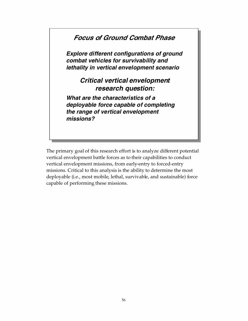
56
The primary goal of this research effort is to analyze different potentialvertical envelopment battle forces as to their capabilities to conductvertical envelopment missions, from early-entry to forced-entrymissions. Critical to this analysis is the ability to determine the mostdeployable (i.e., most mobile, lethal, survivable, and sustainable) forcecapable of performing these missions.
Focus of Ground Combat Phase
Explore different configurations of groundcombat vehicles for survivability andlethality in vertical envelopment scenario
Critical vertical envelopmentresearch question:
What are the characteristics of adeployable force capable of completingthe range of vertical envelopmentmissions?

57
Our plan is to utilize the TRADOC-designed vertical envelopmentbattle forces as the basis for our Blue force analysis effort. Interactionswith the combat vehicle design community and independent analysisat RAND will enable us to accurately model these forces. Concurrentwith this effort, we will generate a challenging set of scenarios that willenable us to explore the capabilities of these strike forces via our high-resolution simulation tools. Lastly, we will assess force performance inthe nonlinear vertical envelopment battlefield by using a variety ofmeasures of effectiveness that can capture the impact of proposedvertical envelopment concepts, such as disruption, shock, and delay ofenemy forces.
Ground Combat Analysis Plan
• Accurately model TRADOC vertical envelopmentbattle force
• Interact with ground vehicle developmentcommunity to establish characteristics of groundvehicles
• Create challenging threat ground force (laydown,capabilities, and tactics)
• Use JANUS (with APS, MADAM, C2 models),CAGIS, and ASP to explore ground vehicle options
• Assess force performance using variety of MOEs
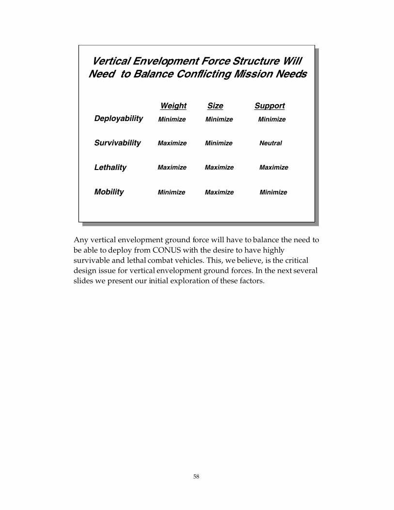
58
Any vertical envelopment ground force will have to balance the need tobe able to deploy from CONUS with the desire to have highlysurvivable and lethal combat vehicles. This, we believe, is the criticaldesign issue for vertical envelopment ground forces. In the next severalslides we present our initial exploration of these factors.
Vertical Envelopment Force Structure Will Need to Balance Conflicting Mission Needs
Deployability
Survivability
Lethality
Mobility
Weight Size Support
Minimize Minimize Minimize
Maximize Minimize Neutral
Maximize Maximize Maximize
Minimize Maximize Minimize

59
To quantify the deployability issue we analyzed Air Force mobilitycommand documents for proposed strategic lift capacity in the year2020. The chart shows how fast an 18,000-ton strike force would bedeployed, assuming different levels of available lift and numbers ofairfields. For example, with two airfields and 100 percent of strategiclift, one task force would deploy in six days by air. Shorter deploymentdistances, more airfields, and faster ground operations could reducethis time to under five days. To first order, however, our initialanalysis indicates that strategic lift will limit how fast the verticalenvelopment force can be deployed.
Combinations of lighter forces and prepositioned equipment should beanalyzed to enhance the deployability of the force. Other deploymentoptions, such as fast ships, could also be examined.
Further research on deployment options will be critical as the verticalenvelopment battle force is further defined.
Strategic Deployability
Air Force heavy lift fleet (2020) Operational rates for aircraft
120 C-17s C-17: 82%
126 C-5s C-5: 72%
Cycle time for SWA deployment: 72 hours Sortie rate per airfield: 1 per hour
C17s needed to deploy Air Expeditionary Force: 70
0
10
20
30
40
50
60
70
80
90
10 20 30 40 50 60 70 80 90 100
2 airfields
1 airfield
Days todeploy
18,000-tonstrike force
Strategic airlift fleet allocation (%)(Fewer C-17s for AEF deployment )

60
APS Can Increase the Level of Vehicle Protection Without Large Increases in Vehicle Weight
0 10 20 30 40 50 60 70 80
Weight (tons)
Level ofProtection(Frontal Arc)
Current US Vehicles
Upgraded with APS
Envisioned by SARDA a
Envisioned by TRADOC b
140mm KEP
125mm KEP
LOSAT
Hellfire
TOW II
HEAT
RPG/PGMM
45mm cannon
30mm cannon
Small arms,artillery frag’s
M1A2
M1A1
M60
M48
M113
M2A1
M2A2
LAV-25
Anti-KE
softkill
SLID
Carrier
Fighter2-le
vel hard kill
ARV
AFV
IFV
TK2000
a: July 1998 SARDA briefingb: 1997 AAN Game Book
This chart illustrates two important vertical envelopment issues. First, itshows where SARDA and TRADOC have envisioned future vehicleswill be in terms of protection and weight. Second, it shows the degreeof extra protection that active protection systems (APS) can provide toexisting vehicles with relatively small increases in vehicle weight. TheAPS consists of a sensor that detects an incoming missile and aneutralizing mechanism, such as an intercept missile or an explodingcloud of ball bearings.
The y-axis on this chart indicates the maximum level of protectionassociated with a vehicle, in terms of the most lethal type of threat thatit can protect itself from under ideal circumstances. Such protectiongenerally occurs when a threat is approaching the front of the vehicle,where the armor is thickest, and the APS (if any) performs as intended.
A selection of U.S. vehicles currently in use are shown in blue. The redline shows the level of protection that a subset of these U.S. vehicleswould have if upgraded with various types of APS. The dashed arrowsconnect current vehicles to their corresponding APS variants, and thelabels indicate the particular APS type.
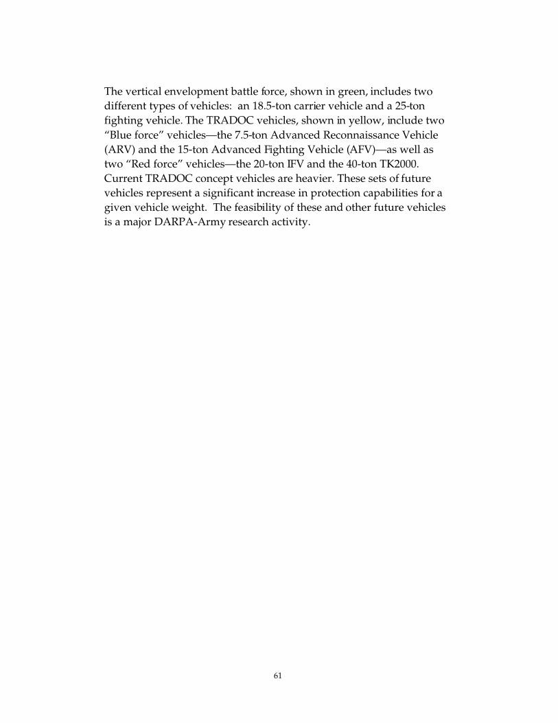
61
The vertical envelopment battle force, shown in green, includes twodifferent types of vehicles: an 18.5-ton carrier vehicle and a 25-tonfighting vehicle. The TRADOC vehicles, shown in yellow, include two“Blue force” vehicles—the 7.5-ton Advanced Reconnaissance Vehicle(ARV) and the 15-ton Advanced Fighting Vehicle (AFV)—as well astwo “Red force” vehicles—the 20-ton IFV and the 40-ton TK2000.Current TRADOC concept vehicles are heavier. These sets of futurevehicles represent a significant increase in protection capabilities for agiven vehicle weight. The feasibility of these and other future vehiclesis a major DARPA-Army research activity.

62
APS Primarily Provides Protection Against Rockets and Missiles
0 1 0 2 0 3 0 4 0 5 0 6 0 7 0 8 0
Weight ( tons)
Level ofProt ection
Current U.S. vehicles
Upgraded with APS
Envisioned by SARDA a
Envisioned by TRADOC b
140mm KEP
125mm KEP
LOSAT
Hellfire
TOW II
HEAT
RPG/PGMM
45mm cannon
30mm cannon
Small arms,artillery frag’s
M1A2
M1A1
M60
M113
M2A1
M2A2
LAV-25
Anti-KE
softkill
SLID
Carrier
Fighter2-le
vel hard kill
ARV
AFV
IFV
TK2000
a: July 1998 briefingb: 1997 Game Book
This version of the protection-versus-weight chart shows an estimate ofthe minimum level of protection for each set of vehicles, as indicated bythe lower boundary of the shaded area under each curve. Thisminimum level is represented by the most lethal type of threat that thevehicle can protect itself from, with high reliability, under challengingcircumstances. In particular, these include situations in which a threatis approaching the vehicle from above or from the rear, where its armoris thinnest.
The most notable feature of this chart is the narrowing of the protection“wedge” for APS-upgraded vehicles, shown in red. This indicates thatadding a low-end APS to lightweight vehicles does not raise theirballistic protection level, while adding a high-end APS to heaviervehicles does raise their protection level. The reason for this differenceis quite intuitive. Lighter vehicles must rely on their relatively thinarmor to protect themselves against intermediate threats. For example,a vehicle with 30mm cannon minimum protection can add an APS toboost its maximum protection from rocket propelled grenades (RPG),but this would not raise its ballistic protection level, since the APScannot address 45mm cannon threats. Heavier vehicles, however, canhandle these intermediate KE threats

63
because they have better passive protection. This additional armor alsoaids the APS in the protection against large KE threats. This happensbecause high-end APS work by breaking up the large KE projectiles.The armor on these vehicles will be needed to stop the projectilefragments from penetrating.
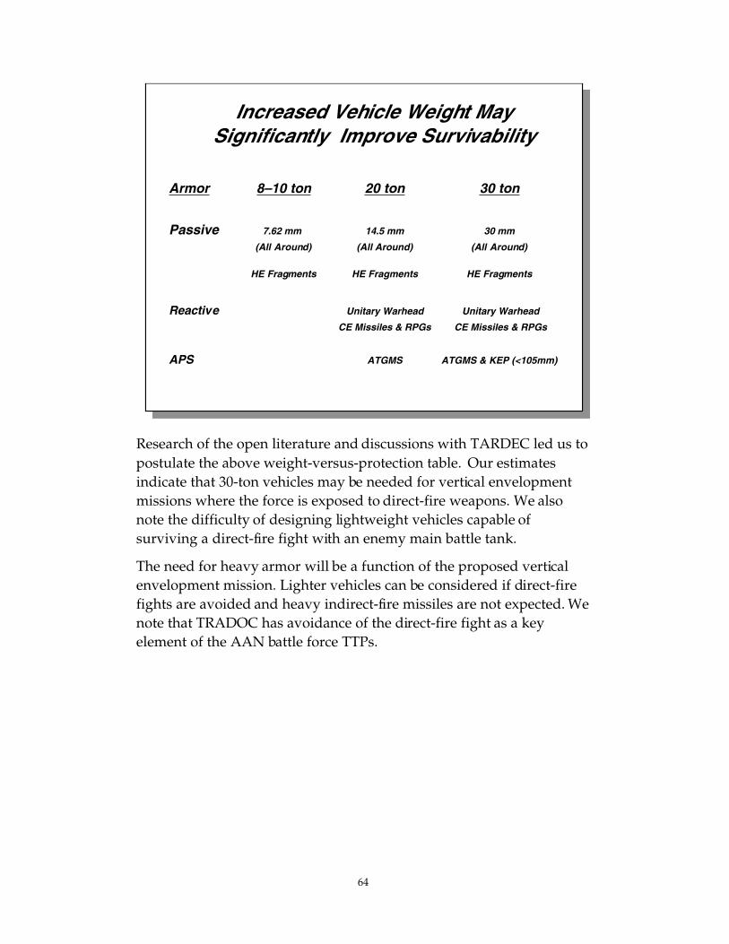
64
Research of the open literature and discussions with TARDEC led us topostulate the above weight-versus-protection table. Our estimatesindicate that 30-ton vehicles may be needed for vertical envelopmentmissions where the force is exposed to direct-fire weapons. We alsonote the difficulty of designing lightweight vehicles capable ofsurviving a direct-fire fight with an enemy main battle tank.
The need for heavy armor will be a function of the proposed verticalenvelopment mission. Lighter vehicles can be considered if direct-firefights are avoided and heavy indirect-fire missiles are not expected. Wenote that TRADOC has avoidance of the direct-fire fight as a keyelement of the AAN battle force TTPs.
Increased Vehicle Weight MaySignificantly Improve Survivability
Armor 8–10 ton 20 ton 30 ton
Passive 7.62 mm 14.5 mm 30 mm
(All Around) (All Around) (All Around)
HE Fragments HE Fragments HE Fragments
Reactive Unitary Warhead Unitary Warhead
CE Missiles & RPGs CE Missiles & RPGs
APS ATGMS ATGMS & KEP (<105mm)
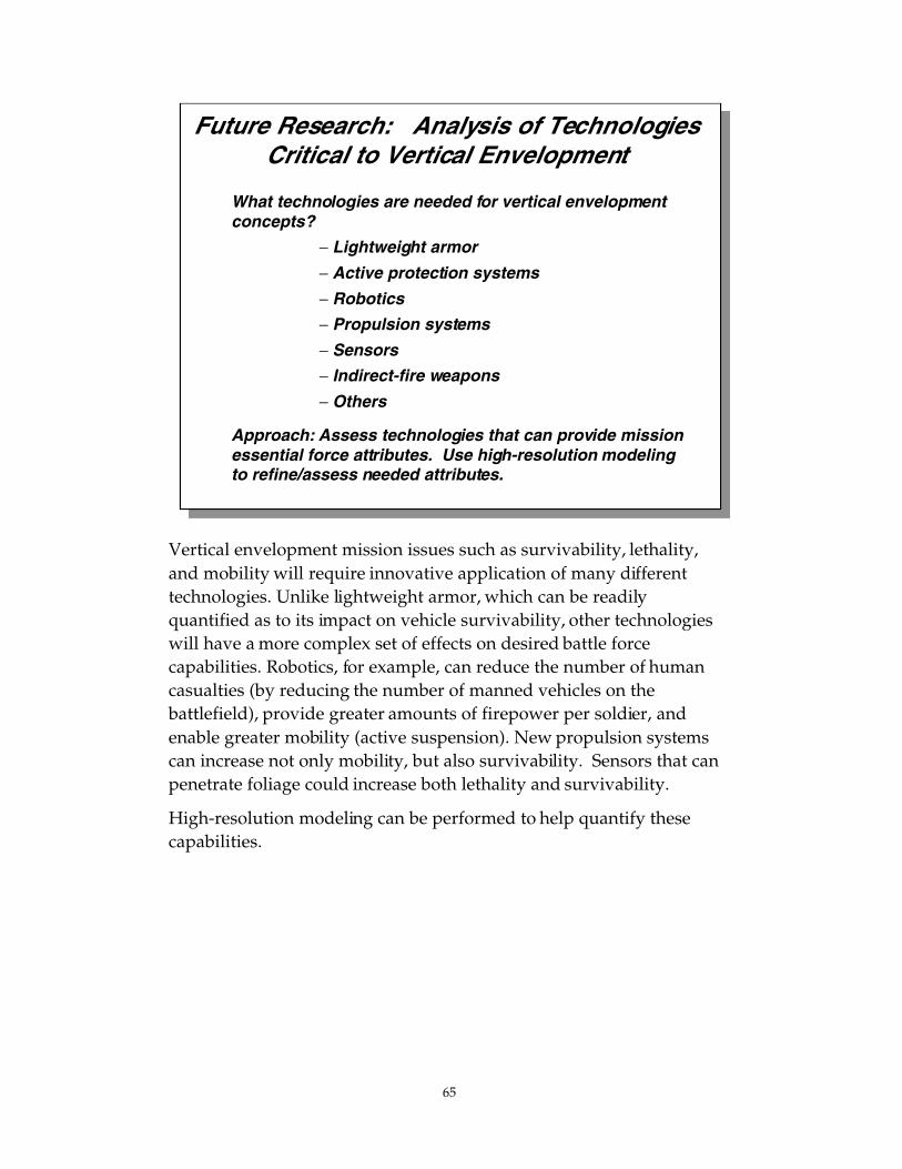
65
Future Research: Analysis of Technologies Critical to Vertical Envelopment
What technologies are needed for vertical envelopmentconcepts?
− Lightweight armor
− Active protection systems
− Robotics
− Propulsion systems
− Sensors
− Indirect-fire weapons
− Others
Approach: Assess technologies that can provide missionessential force attributes. Use high-resolution modelingto refine/assess needed attributes.
Vertical envelopment mission issues such as survivability, lethality,and mobility will require innovative application of many differenttechnologies. Unlike lightweight armor, which can be readilyquantified as to its impact on vehicle survivability, other technologieswill have a more complex set of effects on desired battle forcecapabilities. Robotics, for example, can reduce the number of humancasualties (by reducing the number of manned vehicles on thebattlefield), provide greater amounts of firepower per soldier, andenable greater mobility (active suspension). New propulsion systemscan increase not only mobility, but also survivability. Sensors that canpenetrate foliage could increase both lethality and survivability.
High-resolution modeling can be performed to help quantify thesecapabilities.

66
Scenario/Concept Development for Vertical Envelopment Force Analysis
Close Terrain Mixed Terrain Open Terrain
OffensiveScenario
DefensiveScenario
Focus research here
Assumptions: • Enemy force held constant, approximately a division in each scenario• Each Blue force will confront an identical enemy, in identical terrain• Two Blue forces will be assessed, based on 8- to 10-ton and 30-ton vehicles
Develop insights onvehicles, force
design, and operational concepts
Program limitations usually require a judicious selection of the smallnumber of scenarios/vignettes we can analyze. We plan to use a singlescenario with a variety of mixed terrain to enable us to see effectsresulting from both open and close terrain. We also plan to develop oneoffensive and one defensive vignette. Vertical envelopment forces withdifferent vehicle weight classes will then be examined. While the totalnumber of cases examined will be limited, we believe the range ofparameter space explored will be sufficient to provide key insights onvertical envelopment concepts.
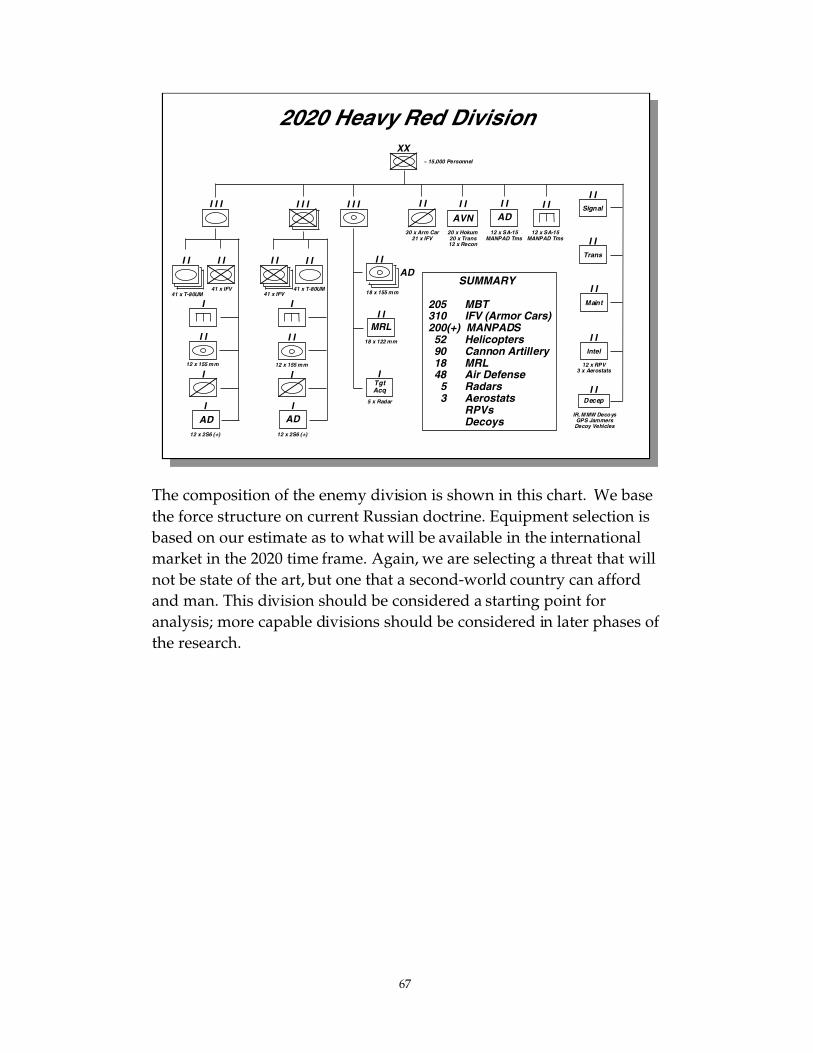
67
The composition of the enemy division is shown in this chart. We basethe force structure on current Russian doctrine. Equipment selection isbased on our estimate as to what will be available in the internationalmarket in the 2020 time frame. Again, we are selecting a threat that willnot be state of the art, but one that a second-world country can affordand man. This division should be considered a starting point foranalysis; more capable divisions should be considered in later phases ofthe research.
2020 Heavy Red Division
41 x T-80UM41 x IFV
12 x 2S6 (+) 12 x 2S6 (+)
TgtAcq
XX
I I I I I I I IADI I Signal
I I
Trans
I I
Maint
I I
Intel
I I
DecepI I
I I
I I
I I
I
I
I
I I
ADI
I
I
I I I I
I I
41 x IFV41 x T-80UM
12 x 155 mm 12 x 155 mm
18 x 122 mm
18 x 155 mm
5 x Radar
30 x Arm Car21 x IFV
12 x SA-15MANPAD Tms
12 x SA-15MANPAD Tms
I II I
AVN
IR, MMW DecoysGPS Jammers
Decoy Vehicles
12 x RPV3 x Aerostats
20 x Hokum20 x Trans12 x Recon
SUMMARY
205 MBT310 IFV (Armor Cars)200(+) MANPADS 52 Helicopters 90 Cannon Artillery 18 MRL 48 Air Defense 5 Radars 3 Aerostats RPVs Decoys
~ 15,000 Personnel
MRLI I
I
I I I
AD
AD

Lay
do
wn
of
En
emy
Gro
un
d F
orc
eM
od
ifie
d 2
020
Div
isio
n—
Blu
e F
orc
e D
efen
se
Mai
nt
I
I I II I
I
II
Inte
l
I I
Sig
nal
I I
Dec
ep
I I
I
I I AV
NH
Q
I I
I II I
I I I I
I
I
I I
I I
I I
I I II
I I II
I I II
I I AD
A
IA
DA
IA
DA
IA
DA
I I MR
L
I I
I I
I I
I I Art
yH
Q
I Tgt
Acq
I I
I II I
I II I
I I
I I
XX
HQ
I II I
Tran
s
I
Tran
s
I
Tran
s
IM
ain
t
I
Mai
nt
I
BU
# 3
BU
# 1
BU
# 2
200
km
68

69
Our initial estimate of the laydown of the enemy division ground forceis shown in the figure on page 68. In our defensive scenario, the enemydivision attacks three vertical envelopment battle units.
The area shown on the map is roughly the size of the Kuwaiti theater ofoperations (KTO) during the 1991 Persian Gulf War, approximately250 × 250 kilometers. The terrain is that of Poland. It consists of openspaces mixed with mountains, cities, and forests.

70
Assessments of the different vertical envelopment concepts begin withenemy attrition (and own losses) as the primary measure ofeffectiveness (MOE). The dynamics of the nonlinear verticalenvelopment engagements are such that disruption of the enemyoperation—denying him the ability to move or resupply, slowing hisprogress, dispersing his forces, or degrading his coordinationcapabilities—may be as important as attrition. Shock effects (heavylosses over a short time, in small areas, or of key systems) may alsodisrupt the advance.
Effectiveness Can Be Gauged by Level of Destruction or Degree of Disruption
Level ofdestruction(attrition)
Comprehensivelethality
Notional requirementfor success
Continuousdetractor
Key to successis to change
enemy behavior
Degree of disruption(loss of tempo)
Level ofdestruction(attrition)

71
RAND Research on High Levels of Operational Maneuver
Level ofdestruction(attrition)
Degree of disruption(loss of tempo)
Comprehensivelethality
Notional requirementfor success
Continuousdetractor
Case 3
Case 1
Case 2Case 4
Case 1:Standofffires alone
Case 2:Standoff &maneuver(Bn)
Case 3:Standoff &agilemaneuver(Red ignores/Red uses arty)
Case 4:Standoff &agile maneuveragainstsoft targets
RAND has performed research on rapidly deployable verticalenvelopment–type forces for over a decade. This chart shows theresults of recent work for the Defense Science Board (DSB).* We believethis ”spanning the range” analysis has implications for verticalenvelopment analysis. The salient points of this RAND analysis on highlevels of operational maneuver are presented below.
Case 1, which involved the aggressive use of standoff fires, resulted in aless-than-decisive 12 percent attrition of the overall enemy force. Oneadvantage of this concept was that because direct exposure to theenemy was minimal, no losses occurred—assuming high-altitudeJSEAD was successful. Case 2, which involved both standoff fires andwhat might be considered a conventional ground force insertion,provided somewhat increased lethality (and robustness), but at the costof considerable losses to the U.S. force.
Case 3, involving the insertion of medium-weight strike force teams toambush the enemy, represented a substantial increase in lethality
___________________
*John Matsumura et al., Joint Operations Superiority in the 21st Century: Analytic Supportto the 1998 Defense Science Board, Santa Monica, CA: RAND, DB-260-A/OSD, 1999.

72
from cases 1 and 2. Organic direct and indirect fires each contributedas many kills as standoff fires. In fact, due to the shock of the ambush,enemy losses of 50 percent demonstrated in case 3 may well besufficient to disrupt the enemy march. If so, fewer direct-fire ambushesmay need to be triggered, reducing U.S. losses further.
In case 4 the same strike force teams engage resupply and C2 elementsrather than combat elements. This represents a significant departurefrom the way we think about assessing force effectiveness. Rather thana force-on-force engagement analysis, this tends to be a force effectsanalysis, where most of the effects may be non-attrition-based. Thus, tosome extent we’ve only begun to characterize the effects of this concept.Initial work indicates this case results in substantial amounts ofdisruption.

73
Insights from our Defense Science Board research also highlight criticalresearch issues for the vertical envelopment ground force.
The DSB work showed that standoff munitions by themselves may notbe able to stop an advancing enemy. Specifically, they can be poorlymatched to an enemy using speed and cover during his advance. Theycan, however, shape the battlefield and significantly enhance theeffectiveness of the ground maneuver force. Future verticalenvelopment analysis needs to include and optimize the role ofstandoff munitions.
The limited ability to transport forces from CONUS can be balancedout, to a certain extent, by quickly transporting the forces about thebattlefield. Overall vertical envelopment mission success will dependheavily on understanding the balance needed between strategic andoperational mobility capabilities.
Lastly, the DSB analysis showed that a thinking enemy can be verydifficult to defeat. His ability to use cover when moving, utilize nettedair defense, disperse his forces, and mix the types of vehicles in theforce makes conventional attack options decreasingly effective.
RAND DSB Study Insights Relevant to Vertical Envelopment Concept Development and Analysis
Combination of engagement and maneuver capabilities is requiredfor joint force robustness
• Standoff engagement offers tremendous potential to shape battleconditions, but comes with key physical limitations
• Agile maneuver allows control of terrain and enemy action, butcomes with inherent risk
New strategic and operational mobility capabilities, to someextent, may be able to offset each other
Lighter ground force systems may be required for agile maneuver(early-entry) missions
Weapons may be limiting factor for standoff engagement
Responsiveness of fires is critical when the enemy can movebetween cover
Foliage penetration can be critical for both sensors and weapons

74
The last section summarizes the insights from work we performed in1998. The study, which was originally intended to be a multi-yearresearch effort, was limited in what research could be and wasperformed in one year. We present these insights with the caution thatthey represent our initial assessments of a highly complex problem. Theinsights are meant to be helpful suggestions for focusing some researchefforts on areas we believe will be important for the success of GeneralShinseki’s vision of the medium-weight Objective Force.
Outline
• Methodology
• Scenario
• Air maneuver phase
• Ground combat phase
• Insights

75
Insights
Lifters may be able to survive mission if combination oftactics and technologies are used:
• Flying low and fast stealthy aircraft with good situational awareness,and SEAD of critical SAM sites
• Flying high during most of the insertion with suppression of high-altitude systems
Methods to suppress/neutralize AAA, IR SAMs, and otherman-portable weapons need further research anddevelopment
Medium-weight vehicles may be able to engage the enemyin a direct-fire fight up to the 105mm cannon level
Strategic lift capability will limit the type of verticalenvelopment force that can be deployed from CONUS
The study, while limited in its efforts, did generate some initial insightsthat we believe are important observations for research activitiescurrently being performed for General Shinseki’s transformation visionand resultant Objective Force.
This study concentrated on the air-insertion phase of the verticalenvelopment air-mech concept. We demonstrated that there were twoapproaches that could enable the ground force to be inserted. Flyinglow enables the usage of terrain masking and is appropriate in areaswhere long-range SAMs are operating. Flying high works better if long-range SAMs are suppressed.
Knowledge of the SAM site locations was shown to enhance aircraftsurvival rates. In several cases, however, the pilot could not alwaysavoid these sites. While in most cases these missions would not beflown, there may be cases where there is no choice. Developing TTPsand new countermeasure technology is essential for the successfulexecution of these current high-risk missions.
Finally, we note that optically and IR guided ADA systems will be hardto detect and can limit vertical envelopment aircraft survival rates.

76
Our ground vehicle research showed that lightweight armor and APStechnologies could be used to build medium-weight vehicles (20–30tons) capable of surviving attacks from weapon systems up to a 105mmcannon round.
Lastly, we examined the Air Force’s strategic lift capability, and ourinitial analysis indicated that it is limited to about 3,000 tons a day. Thevertical envelopment force design needs to reflect this limited airdeployment capability.

77
The air-insertion analysis performed in this study provided significantinsights. Due to its limited duration and scope, the study identified butdid not fully examine two critical areas of research.
One key area for further research is to develop an understanding of thelimiting effects of optically guided anti-aircraft munitions. Furtherstudy is needed to better quantify the magnitude of this problem.Given its potential severity, additional research on technologies tocounter this problem is also warranted. One approach in particular,stealth fixed-wing aircraft, could potentially provide a viable, butexpensive, solution to this problem. Another solution is to develop newair-insertion tactics, the second critical area of future research efforts.
In this initial study we looked at only two sets of air-insertion tactics.Other tactics listed on this chart have the potential to significantly raisethe probability of successful insertion of the vertical envelopment battleforce.
Air Maneuver Phase: Unanswered Questions
Technology
• The effects of small arms fire on mission survivability
• Future RF, IR, and AAA countermeasures
• New optical and IR stealth concepts
Investigation of alternative air-insertion tactics
• Fly to perimeter of enemy air defenses; then drivevehicles to fighting locations
• Unmanned insertion of vehicles
• SOF-aided missions
• Cross-FLOT ADA suppression techniques

79
BIBLIOGRAPHY
Cassady, J. F., Transportability for Better Strategic Mobility, MTMCTEA Pamphlet70-1, 1987.
Fratzel, Margaret A. (prepared by), Analysis Plan for the Army After Next: FallWargame, November 1996 and Winter Wargame, January–February, 1997, FortLeavenworth, KS: TRAC Study and Analysis Center, January 10, 1997.
Fuel-Efficient AAN Task Group (prepared by), Fuel-Efficient Army After Next,White paper, March 1997.
Grange, David, et al., Air-Mech-Strike: 3-Dimensional Phalanx; Full-SpectrumManeuver Warfare to Dominate the 21st Century, Paducah, KY: TurnerPublications, August 2000.
Grant, Rebecca, The Radar Game, Arlington, VA: IRIS, 1998.
Grimes, V. P., “U.S. Army Begins Digitization Build-Up,” International DefenseReview, August 1994, pp. 51–54.
Hewish, M., and Ness, L., “Shoot First, Ask Questions Later: Smart Tanks Learnto Fend for Themselves,” Jane’s International Defense Review, Vol. 29, March1996, pp. 33–36.
Hudson, Richard D., Jr., Infrared Systems Engineering, New York: John Wiley andSons, 1969.
Jane’s 1998–1999 Land-Based Air Defence, Jane’s Information Group, Surrey,England, 1998.
Joint Chiefs of Staff, Joint Vision 2010: America’s Military: Preparing for Tomorrow,Pentagon, Washington, D.C., n.d.
Killebrew, Robert B., “The Army After Next: TRADOC’s Crystal Ball Eyes theServices’ Shape Beyond Force XXI,” Armed Forces Journal International, October1996, pp. 36–45.
80
Marine Corps Combat Development Command, Close Support End-to-EndAssessment (CSEEA) Military Operations in Urban Terrain (MOUT) Seminar WarGame: ASSESSMENT, Quantico, VA: 1997. (For official use only.)
Matsumura, J., R. Steeb, T. Herbert, M. Lees, S. Eisenhard, J. Gordon, andG. Halverson, The Army After Next: Exploring New Concepts and Technologies forthe Light Battle Force, Santa Monica, CA: RAND, DB-258-A, 1999.
Matsumura, J., R. Steeb, T. Herbert, M. Lees, S. Eisenhard, and A. Stich, AnalyticSupport to the Defense Science Board: Tactics and Technology for 21st CenturyMilitary Superiority, Santa Monica, CA: RAND, DB-198-A, 1997.
Matsumura, J., Steeb, R., Isensee, E., Herbert, T., Eisenhard, S., and Gordon, J.,Joint Operations Superiority in the 21st Century: Analytic Support to the 1998Defense Science Board, Santa Monica, CA: RAND, DB-260-A/OSD, 1999.
Morningstar, James K., “Javelins and Skirmishers on the Battlefield,” ARMOR,May–June 1996, pp. 37–40.
Nathanson, Fred E., Radar Design Principles, New York: McGraw-Hill, 1969.
Packett, Virgil L., II, Air Mechanization: The Direction and Dynamics of ArmyAviation from a Combined Arms Perspective, thesis, U.S. Army Command andGeneral Staff College, Fort Leavenworth, KS, 1985.
Pinder, J.D., A Generic Parameterized Model of Active Protection Systems for MilitaryVehicles, MORS 1998 paper WG -29.
Steeb, R., K. Brendley, T. Covington, T. Herbert, and S. Eisenhard, Light Forces:Heavy Responsibilities: The Role of Technology in Enabling Future Early EntryForces to Fight and Survive, Santa Monica, CA: RAND, MR-473-ARPA, 1995.(For government use only: not available to the public.)
Steeb, R., J. Matsumura, T. Covington, T. Herbert, S. Eisenhard, and L. Melody,Rapid Force Projection Technologies: A Quick-Look Analysis of Advanced LightIndirect Fire Systems, Santa Monica, CA: RAND, DB-169-A/OSD, 1996.
Steeb, R., J. Matsumura, et al., Rapid Force Projection: Exploring New TechnologyConcepts for Light Airborne Forces, Santa Monica, CA: RAND, DB-168-A/OSD,1996.
Stix, G., “Fighting Future Wars,” Scientific American, December 1995, pp. 92–98.

81
U.S. Army Materiel Command, Precision Munitions in Army Vision 2010: A VitalComponent of Decisive Operations, Picatinney Arsenal, NJ: TACOM-ARDEC,n.d.
U.S. Army Training and Doctrine Command, Army After Next: 1997 WinterWargame, 27 January–6 February 1997—Game Book, Fort Monroe, VA: DoctrineDirectorate, U.S. Army Training and Doctrine Command, 1997. (For officialuse only.)
U.S. Army Training and Doctrine Command, Army After Next: 1997 WinterWargame, 27 January–6 February 1997—State of the World 1995–2020, FortMonroe, VA: Doctrine Directorate, U.S. Army Training and DoctrineCommand, 1997. (For official use only.)
U.S. Army Training and Doctrine Command, Force XXI Operations, Fort Monroe,VA, Pamphlet 525-5, 1994.