predictive mineral discovery - … · predictive mineral discovery ... expansion of the crc’s...
TRANSCRIPT

Predictive mineral discovery COOPERATIVE RESEARCH CENTRE
Final Report
Modelling Program December 2001
to June 2005
Projects: M1, M2 & M3
Table of Contents
Executive Summary........................................................................................................................................... i Introduction....................................................................................................................................................... 3 Project M1 – Modelling Software Framework .............................................................................................. 6
Introduction .................................................................................................................................................... 6 Modelling Workflow ....................................................................................................................................... 6 The Software Framework ............................................................................................................................... 8 Desktop Modelling Toolkit ............................................................................................................................. 8 Templates and Wizards................................................................................................................................... 9 Inversion and Sensitivity Analysis ................................................................................................................ 10 Access to data ............................................................................................................................................... 11
Project M2: Earth Process Software Development .................................................................................... 13 Introduction .................................................................................................................................................. 13 Sub-project M2.1 - Quantitative modelling of rock brittle behaviours in a hydrothermal environment ..... 14 Sub-project M2.2 - Quantitative modelling of magmatic processes – emplacement, thermal effects, and fluid generation............................................................................................................................................. 44 Students......................................................................................................................................................... 47
Project M3 - Applications of Numerical Modelling..................................................................................... 50 Introduction .................................................................................................................................................. 50 Non-Terrane Modelling Projects.................................................................................................................. 51 Exploration Modelling Template Development............................................................................................ 58 Modelling Library......................................................................................................................................... 61 Course Development..................................................................................................................................... 63
Presentations/Publications ............................................................................................................................. 65 References........................................................................................................................................................ 70

Executive Summary i
Executive Summary
The pmd*CRC Modelling Program was established to provide the numerical modelling (i.e. computational simulation) capability required for ore targeting and hence predictive discovery. It aims to deliver:
• The required software capability for predictive simulation of mineral systems at all scales,
• A methodology for using this software for ore discovery,
• A record of ore discovery using the software and methodology,
• Educational outputs to help train geoscientists to employ this new approach in their day-to-day exploration, and
• A team of expert users who can carry on the work of predictive discovery using the software and methodology after the CRC ends.
In Stage 1 of the CRC ending in June 2005, the above outputs were addressed by the three projects in the Modelling Program (M1, M2 and M3), along with some activities in the Fluids Program (in project F1/F2) and various one-on-one projects (e.g. Stawell, Kundana etc).
Improvements to software and algorithms in projects M1 and M2 of the Program were aimed at delivering both efficiency gains and more realistic simulations of geological processes. Activities in project M3 were aimed at the last three outputs in the above list.
Advances made in Stage 1 of the CRC included the following:
1) Improved efficiencies in the workflow so that the process was at least ten times more efficient in June 2005 than it was when the Modelling Program commenced. In particular, efficiency gains were achieved through:
• advances in mesh generation through the invention of FLAC3D templates, GOCAD wizards and increased use of PATRAN;
• the application of inversion in geology routines to help expert users undertake large scale parameter searches;
• improved visualisation capabilities through developments in FracSIS and the use of other visualisation tools (e.g. Mayavi)
2) Improved capabilities to simulate geological processes through:
• Introduction and testing of advective heat transport algorithms in FLAC and FLAC3D,
• Particle code experiments of rock fracture development permitting calibration against rock deformation experiments,
Executive Summary ii
• Application of damage mechanics and the Cam Clay constitutive behaviour model to simulating fracture and permeability development in the upper crust,
• Development of new reactive transport software using FastFlo4 for prediction of alteration and mineralisation (where thermodynamic data permits) in time and space (also developed partly in the project F1/F2), and
• Development of a methodology for coupling deformation, fluid flow, heat and reactive transport modelling codes together using FLAC3D and WinGibbs. Unfortunately, this proved to be too computationally inefficient to enable useful application to mineral exploration problems.
3) Development of a modelling workflow, which provided a basis for prioritising software developments, and consisting of five major steps:
• Analyse the exploration/geological problem,
• Build geometry in a form suitable for 3D computational simulation,
• Do the computational simulations,
• Visualise the outputs,
• Interpret and report on the results.
4) Development of reference and learning materials in the Modelling Library and short courses for industry personnel and postgraduate students.
5) Expansion of the CRC’s modelling team so that it is available to address industry targeting problems within moderately short time frames (generally less than 3 months).
This report provides an overview of activities in the three projects in the Modelling Program, along with significant supporting information (in electronic form) drawn from the various project TWiki’s.

Pmd*CRC M1, M2 & M3 Final Report October 2005 _______________________________________________________________________________________________________
Introduction The pmd*CRC’s Modelling Program was established to provide the numerical modelling (i.e. computational simulation) capability required for ore targeting and hence predictive discovery. It is the largest of the CRC’s “enabling technology streams”. Its stated objectives, as laid out in the CRC Application and Centre Agreement, are to:
• Develop environments for the management, storage and transfer of the data from field observations to numerical modelling using XMML.
• Develop and implement three dimensional very-large-deformation thermo-mechanical modelling packages (with modules for porous-flow, multi-phase-flow, chemistry, erosion) capable of realistic physical simulation of geomaterials, and geological structures on an extreme range of scales.
• Design and implement an Interactive Visual Modelling System (IVMS) based upon these three dimensional very-large-deformation, thermo-mechanical, chemical, fluid flow modelling packages.
The Program has evolved considerably since 2000 when the above words were first written. The research effort has now focussed down to the task of developing a numerical modelling capability which can deliver predictive value in the short time frames of a typical exploration program. While progress has been made against all of the objectives outlined above, it is difficult to use them to measure the Program’s effectiveness against the overall goal of predictive discovery. Thus, the following provides a more tangible picture of the Program’s direction:
By June 2008, the Program aims to provide exploration and mine geologists with access to a service that will enable them to reduce mineral targeting costs in the time frame of a typical exploration program. In a range of ore environments and across a range of scales, they will be able to:
1) Directly predict location of ore from a 3D computer model of geology, where the geology (including conceptual understanding of ore forming processes) is both simple and well known enough to be modelled directly (e.g. at Stawell)
2) Predict probable location of ore in 3D space by translating a spatially predictive understanding of ore control (structure, host rocks etc) derived from a suite of computer models of ore formation into 3D interpretations of geology (constructed using Vulcan, GOCAD etc), where the geology is well known enough to generate a 3D interpretation
3) Predict the detectable geological, geophysical or geochemical characteristics (signatures) of ore or ore-related alteration through the use of generic computer models (in order to enable explorers to customise their data

Pmd*CRC M1, M2 & M3 Final Report October 2005 _______________________________________________________________________________________________________
acquisition strategy - so as to maximise likelihood of ore detection and minimise cost), where a 3D geological interpretation is not possible.
In order to do these things well, the Modelling Program must:
1) Accurately address a wider range of geological process problems than is now possible,
2) Make computational modelling (simulation) systems more efficient,
3) Address the people issues e.g. training, client understanding of the process.
Most of the benefits from the Modelling Program are being realised through the work of expert users as the cost and difficulty of engineering a system which is usable directly by industry geologists is too great for the CRC’s resources. Increasing the effectiveness of the expert users’ work depends principally on improvements to the modelling workflow, which consists of the following major steps:
1) Analyse the exploration/geological problem
2) Build geometry in a form suitable for 3D computational simulation
3) Do the computational simulations
4) Visualise the outputs
5) Interpret and report on the results.
The Modelling Program effectively commenced in December 2001, with a workshop in which various project priorities were established. Three inter-related projects emerged from the workshop’s deliberations – one to develop the software (M1), a second to develop the science associated with computational simulation of rock and fluid behaviours (M2) and a third aimed at outreach, i.e. application of the software and science to exploration-related problems and education and training (M3). These three projects all commenced in the first half of calendar 2002 and concluded at the end of June 2005 (“Stage 1” of the Modelling Program).
The project structure evolved somewhat during Stage 1. This was because both the Modelling and Fluids Programs were aimed at developing chemical modelling technologies, the former being focused on reactive transport and the latter on reactor-style modelling. For this reason, the reactive transport effort was transferred into the Fluids Program during 2003. When the first stage of the latter Program concluded in February 2005, the reactive developments continued under the auspices of project M2. Nonetheless, to avoid overlap, information on reactive transport developments in the CRC is provided in reports from the Fluids Program.

Pmd*CRC M1, M2 & M3 Final Report October 2005 _______________________________________________________________________________________________________
Project personnel and leadership also changed during Stage 1. People with geological, mathematical, physical, chemical, and computational skills, or at least some suitable mix of these, are still rare. The situation is slowly improving, as computational geoscience becomes more accepted throughout the world, and locally, as the pmd*CRC Education & Training strategy unfolds. The most successful hiring strategy remains attendance at conferences, publication, and advertisement through the Internet. New staff that were recruited to spend all or part of their time on the three projects included:
• Paul Roberts – ex-industry geologist/exploration manager,
• Warren Potma – ex-industry structural geologist,
• Klaus Gessner – structural geologist (initially a staff member at CSIRO, Klaus successfully applied for the UWA-based Earth Systems Modelling Group leader role during this period),
• Klaus Regenauer-Lieb – researcher in geomechanics and geodynamics,
• Heather Sheldon – postdoctoral fellow in geomechanics,
• Regan Patton – researcher in geomechanics,
• Michael Kuehn – reactive transport modeller,
• Robert Woodcock – software engineer,
• Robert Cheung – software engineer,
• Andy Dent – software engineer,
• Thomas Poulet – applied mathematician, and
• Andrzej Welna – scientific programmer.
Project personnel who departed during Stage 1 included Klaus Regenauer-Lieb (although he continues to retain close research links with the group), Fabio Boschetti, Peter Alt-Epping, Andrzej Welna and Michael Kuehn.
At their commencement dates, projects M1, M2 and M3 were headed by Peter Hornby, Alison Ord and Paul Roberts respectively. As project priorities evolved, Peter Hornby became increasingly involved in developing the reactive transport code, FastFlo-py. The M1 project leadership then passed to Robert Woodcock.
This report is intended to provide an overview of project activities during Stage 1. Therefore, it provides a relatively brief summary of project activities with reference to more extensive documentation which is stored on the pmd*CRC TWiki, copies of which are provided on the enclosed DVD. Thus, while a printed text version is provided, this document is best read from the DVD so that links can be followed.
Pmd*CRC M1, M2 & M3 Final Report October 2005 _______________________________________________________________________________________________________
Project M1 – Modelling Software Framework Project Leader – Dr. Robert Woodcock
Introduction
The visionary goal of this project (from the M1 CRC project agreement) is:
“To develop a software framework which enables industry and government clients to evaluate potential and explore prospective locations (at all scales) for large high value ore bodies far more efficiently than they can do now. To do this, the software framework will encompass a complete set of earth process numerical modelling tools which:
• can be accessed easily at a moderate cost (as much as possible from explorationists’ desktop computers),
• will operate efficiently in providing solutions to complex problems in a time scale of no more than several weeks
• will be useable either individually or coupled together, and
• will provide solutions to most of not all of the process-related problems faced by clients who wish to target or evaluate prospective areas.”
During the course of the project, it became increasingly apparent that the goal of providing the software directly to explorationists was unrealistic, given the likely cost of providing sufficiently intuitive code for them to use. Therefore the focus changed to providing a service that could be effectively and efficiently used by an expert user team.
Stage 1 of the Modelling Program resulted in the development of a number of components in the software framework and significantly improved efficiency and evaluation capabilities. These components have been applied to industry problems and used successfully to produce targeting outcomes. The following sections describe some of the key deliverables of the M1 project.
Modelling Workflow Whilst not directly about software the Modelling Workflow (https://pmd-twiki.arrc.csiro.au/twiki/bin/view/Modellingworkflow/WebHome) is an extremely important driver for the requirements and architecture of the software framework. Just as the science and software matures so do the principles by which the workflow operates. Stage 1 has seen a steady and significant maturing in the Modelling Workflow principles and provided a greater focus for the work ahead in science, software engineering and industry application.

Pmd*CRC M1, M2 & M3 Final Report October 2005 _______________________________________________________________________________________________________
For the purposes of software design, the modelling workflow is broken into five activities:
1. Define the geological problem:
During which the geological processes (heat, mechanics, chemistry, fluid flow) that need to be modelled are identified along with coupling requirements, boundary conditions, material properties and geometry.
2. Build the model(s):
The required geometry is built, material properties gathered from source material and combined with the geometry. If multiple scenarios are required (an inversion for example) then the model may be parameterised using a template so that families of models can be automatically generated.
3. Run the model(s):
depending on the problem this may be as simple as running on the local desktop computer or managing 100 jobs on a compute cluster at a remote location.
4. View and Interpret results:
Visualisation and data mining tools are used to aid the explorer in analysing the results.
5. Report and feed into knowledge base:
Ultimately the interpretation from the modelling results must be applied to the real world problem. This requires integration and synthesis, especially where multiple scenarios are used to quantify the uncertainty.
The software framework must support the modelling workflow and aid its efficient execution. Analysis of the workflow provides a number of key software requirements:
• Ease the data access burden – internal and multi-organizational data is used at all stages, particularly in setting up models
• Flexibility – there is no one possible numerical, visualization or modelling tool, several are usually required
• Sophistication - coupling of codes, complex numerical processes
• Investigation - families of models need to be explored in order to understand what governs the system and reduce uncertainty
• Performance vs complexity balance – creating models and performing computation is significant, sometimes many simple models are better than one complex model
• Multiple scientific disciplines and new codes all the time – the science of mineralization processes is still under development, changes are to be expected
• Model creation (and families) – needs to be efficient

Pmd*CRC M1, M2 & M3 Final Report October 2005 _______________________________________________________________________________________________________
• Accessibility – the framework should be easily accessible, from explorer’s desktop where possible
Above all the workflow must be repeatable, robust and timely which places further demands on the software framework.
The Software Framework
The software framework (https://pmd-twiki.arrc.csiro.au/twiki/bin/view/Swframe/WebHome) consists of a number of components ranging from existing third-party applications to custom pmd*CRC R&D. These have been harmonised through a user-interface with consistent data interchange formats. The harmonisation is essential to achieving efficiency gains as analysis of the modelling workflow shows significant data conversion and integration issues at all stages. The following sections summarise the key components of the software framework developed during Stage 1.
Desktop Modelling Toolkit The Desktop Modelling Toolkit (https://pmd-twiki.arrc.csiro.au/twiki/bin/view/Swframe/DeskMTdownload) is the user-interface for accessing the software framework components. Initially this was implemented as 3D MACS, a web based application accessed via a standard web browser like Internet Explorer. Being web based, 3D MACS could be accessed from anywhere over the internet without the user having to install software. 3DMACS provides data conversion to move model and finite element mesh (FEM) geometry between third-party software packages including GOCAD, FracSIS and Flac3D. It provides forms for specifying model parameters for (optionally) coupled Heat-Mechanical-Fluid flow problems. These models could then be executed by Flac3D. All of these activities could be orchestrated by the user via 3DMACS. 3DMACS used the Exploration and Mining Mark-up Language (XMML) for finite element model interchange. XMML for FEM represented an open format to which other third-party applications could be targeted. As a result data interchange between CAD modelling packages (GOCAD, Patran), numerical solvers (Flac3D, FastFlo4) and visualisation packages (FracSIS, Mayavi) became considerably more efficient. The data interchange component of 3DMACS was its most sought-after feature. XMML for FEM was also adopted by the ACCESS MNRF for use with its Finley and e-script developments. XMML provides support for considerably more information than FEM models. The latest developments include assays, boreholes, chemistry, rock units, etc. As a result the problem descriptions used in the Desktop Modelling toolkit represent a Common Earth Model. This allows for a wide variety of attributes to be associated with many sections of the modelled earth. A single model can now be developed to support mechanical, fluid

Pmd*CRC M1, M2 & M3 Final Report October 2005 _______________________________________________________________________________________________________
flow, chemistry, heat, geophysical, magnetics and a variety of other possible observations, measurements and simulations. This will be increasingly important as more modelling codes and types are added to the toolkit. The Desktop Modelling Toolkit has since evolved into a standard, non-web based, application. The technical reason for this is so interaction with third-party tools can be improved. Web based applications should not, strictly speaking, interact with a users desktop computer. Streamlining the workflow further by integrating directly with tools like Patran for mesh generation and Flac3D for Windows (with its associated dongle license restrictions) required a move to a desktop application. The new application still utilises the data interchange components of 3DMACS and is also capable of distributed access to supercomputers and clusters. The new application will form the basis for the Stage 2 pmd*CRC developments.
Templates and Wizards Creation of a 3D model, or families of models for a sensitivity analysis or inversion, is incredibly time consuming. Generally, different users and tools are efficient under certain situations. As a result the Toolkit uses the XMML for FEM interchange format to allow users to move easily from one tool to the next. The ease of interchange afforded by XMML for FEM allowed new modelling tools, like MSC Patran, to be added to the toolkit easily. Detailed analysis of the modelling workflow also showed a considerable number of repeated, if not routine, stages used in specific tools. GOCAD wizards (https://pmd-twiki.arrc.csiro.au/twiki/bin/view/Pmdcrc/GocadWizards) were developed to provide a quick and easy method for executing common sets of functions. The wizards changed complex multi-stage and repetitive menu clicks and mouse movements into one or two clicks. This significantly reduced the time taken to produce common models like multiple intersecting faults. Creating families of models for inversion was also greatly enhanced through the use of Templates programmed directly into Flac3D and GOCAD (https://pmd-twiki.arrc.csiro.au/twiki/bin/view/Pmdcrc/GocadStuff#Wizards_in_GOCAD). Templates use a predefined topology for model construction, say, 3 vertically oriented faults with 4 horizontal layers of rocks. The dip, strike, curvature, thickness, and other geometric parameters could then be specified by the user or automatically generated by an inversion. The Template could then generate a range of models that had the same basic topology but entirely different geometries. Templates are basically essential when performing inversion or sensitivity analysis. Traditional model generation approaches would simply not be timely enough in production of results. Templates and Wizards have been extensively applied to real world problems in the M3 project. In addition, the automated and step-by-step approach aids in education and training where new users are able to learn and use the toolkit in very short periods of time.

Pmd*CRC M1, M2 & M3 Final Report October 2005 _______________________________________________________________________________________________________
Inversion and Sensitivity Analysis To quantify the uncertainty involved in a geological problem requires an understanding of how different factors (e.g. the dip and strike of intersecting faults) influence the desired outcome (e.g. mineralisation). The process of sensitivity analysis can be used to address this issue by trying many possible scenarios are modelling them to see the results. Analysis for the family of results can then be used to synthesise an interpretation how the different factors impact the result. This can then be used, for example, in targeting by prioritising those targets that have the most favourable factors. Given that the number of possible factors is huge, this process is most often performed in the context of an inversion. Inversion uses an optimisation algorithm to assist the user in moving towards those factors (and parameter ranges) that are most likely to produce the desired outcome. Use of inversion significantly reduces the number of scenarios required to be run in order to produce meaningful results. The optimisation process is guided by rankings of the results provided by the geologists’ interpretation of what the “desired outcome” is and how well the result matches it. The M1 project developed several optimisation algorithms (Genetic Algorithm, Lipschitz), visualisation of how the results group together (using a Sammons map) and a web based user interface to access these (https://pmd-twiki.arrc.csiro.au/twiki/bin/view/Pmdcrc/InversionEarth). The Web application had two modes of operation:
1. manual – in which the user specifies ranking of the results and the web application produces a matrix of the next iterations optimised parameters. The user then “cut and pastes” these into their chosen modelling application
2. automatic – in which the inversion application communicates with the 3DMACS compute services to run the models. The inversion application provides job control and collation of results.
This approach provided flexibility in that the user could utilise software from outside the toolkit for numerical processing when necessary and have significant efficiency gains when 3DMACS compute services (inside the toolkit) could be used. The component nature of the software framework supports this “opt in, opt out” approach and it has proven to be an essential feature at most stages of the workflow. The Inversion application has been used with the CSIRO High Performance and Scientific Computing cluster in Melbourne. The application was used to run 50 models per generation of the Genetic Algorithm optimiser by a modeller in Perth. The 50 models run in a 24 hour period and represented almost 2 weeks computing using the previous approach. Additional iterations (expected to be 8 generations) will be run to complete the analysis and the overall efficiency gain is substantial with improved outcomes being produced in a timely manner.

Pmd*CRC M1, M2 & M3 Final Report October 2005 _______________________________________________________________________________________________________
A standalone version of the Inversion algorithm has since been requested by some pmd*CRC members for geophysics inversion and it will also be integrated into the new Desktop Modelling Toolkit application.
Access to data The modelling workflow requires access to rock properties, geometries, chemical properties, and many other types of data. This is usually sourced from multiple locations including the users company standard exploration software (and there is likely to be many of these) and pre-competitive geoscience data from the Geological surveys. Wherever this data is stored it must be discovered, collected and integrated into single common earth model for numerical modelling to proceed. There is no single format for representing this information and so this process usually involves many, error prone, data conversions for coordinate systems and file formats. There is also the significant task of “simply” discovering and obtaining the data, regardless of format. XMML was developed prior to the pmd*CRC in an effort to solve at least part of this problem, the exchange format. During stage 1 of the M1 project the pmd*CRC, CSIRO, Geoscience Australia and the Chief Government Geologists Committee along with mining companies (represented by the Minerals Council of Australia) and mining software companies developed the Solid Earth and Environment Grid (https://www.seegrid.csiro.au/twiki/bin/view/Main/WebHome). “SEE Grid” is a community of practice promoting the use of web services (like those used in the pmd*CRC software framework) and open standards (XMML) for information exchange. The involvement of the geological surveys provided a focus on access to pre-competitive geoscience data. With additional support from AusIndustry, the SEE Grid community successfully developed a roadmap for accessing pre-competitive geoscience data in a unified and open manner (https://www.seegrid.csiro.au/twiki/bin/view/Infosrvices/SeegridRoadmap). This roadmap was then implemented and demonstrated for Assay (geochemistry) data held by all geological surveys in Australia (http://cgsrv3.arrc.csiro.au/seegrid/savedapps/filter). The information is accessed using open standards and XMML and all State and Territory data holdings for geochemistry can be accessed using a single data query and obtaining a single format of results regardless of how each individual survey stores that data. To highlight the efficiency gains the demonstration included a query of Assays with varying levels of copper or gold content. The spatial extent of the query was the Musgraves region which spans the NT, SA and WA borders. The query returned results from all three geological surveys in a single result set which could then be easily transformed onto a map or loaded directly into Fractal Technologies’ FracSIS database. This result was produced in a few minutes and was reported to have taken several months previously where courier requests, data copying and format conversion were required. The response from Industry and Government organisations has been overwhelmingly positive. The software framework will benefit from the SEE Grid activities as the Fluid Inclusion and Thermodynamics databases held by Geoscience Australia are to be SEE Grid enabled

Pmd*CRC M1, M2 & M3 Final Report October 2005 _______________________________________________________________________________________________________
using the same components developed in the SEE Grid projects. These will then be used as input data to the modelling process. The SEE Grid community and enabling technologies will continue to be developed and enhanced into production grade technology. The pmd*CRC sponsored the SEE Grid 2005 workshop which had over 100 attendees with speakers from all over Australia, the UK and Canada. The main themes of the workshop discussed whether SEE Grid as a community was forming and addressing issues of interoperability and whether SEE Grid had advanced the cause in the past 2 years. The response was very positive with numerous projects and cross-domain activities interacting to produce common approaches and technologies. The SEE Grid website itself now hosts several theme specific collaboration areas (eg. Natural Resources, Exploration and Mining, Grid technologies, Information Services like the Geochemistry demonstrator) and has around 300 subscribers. In addition to this the site has some 500-700 unique visitors per month reviewing the technologies and accessing the standards. Mining and mining software companies have also shown interest in incorporating the standards into their software.

Pmd*CRC M1, M2 & M3 Final Report October 2005 _______________________________________________________________________________________________________
Project M2: Earth Process Software Development Project leader – Dr Alison Ord
Introduction
The visionary goal of this project (from the M2 CRC Project Agreement) was:
“To develop a complete set of earth process numerical modelling tools, encompassing hydrothermal and magmatic process models, to enable testing of multiple scenarios for mineral exploration.
This involves the development of geological conceptual models, as well as of genuine functionality of process modelling software, that will allow the user to model geological processes involved in the formation of hydrothermal and magmatic ore deposits.
The essential processes are:
1. Compaction and fluid flow through porous media incorporating advection of heat.
2. Rock behaviours in a hydrothermal environment.
3. Brittle, plastic, viscous and anisotropic behaviours, and their multi-scaling, and transitions between them.
4. Magmatic processes – emplacement, thermal effects, and fluid generation.
5. Lithospheric scale geodynamic processes to supply regional constraints to mineralising systems; this involves deformation and P-T-t histories, heat flow, time constraints, and mass flux from the mantle.
6. The above processes coupled to chemical processes.
The elements of this computational system are:
1. Continuum codes that enable the simulation of elastic-plastic-viscous materials and related combinations, including anisotropy.
2. Multiphase flow in porous media and fractured rock masses.
3. Codes that enable fracture initiation and propagation controlled by the physics of fracturing rather than by a priori assumptions.
4. Codes that model both conductive and advective heat transport.

Pmd*CRC M1, M2 & M3 Final Report October 2005 _______________________________________________________________________________________________________
5. Codes that enable the mechanics to be fully coupled to mass advection, fluid mixing, and reactive transport.
6. Codes that enable the modelling of magmatic systems.
7. Multi-scaling so that the ability exists to take the results of modelling at a coarse scale as boundary conditions for models at a finer scale, with feedback from the finer scale back to the coarse scale.
All of these elements will be coupled so that feed back reactions of one process upon others can be managed.”
Sub-project M2.1 - Quantitative modelling of rock brittle behaviours in a hydrothermal environment
“To develop a quantitative modelling system capable of realistically simulating brittle behaviours of deforming rocks with a full coupling with fluid flow and thermal transport. These brittle behaviours include: fracture-fault generation and propagation, rock brecciation due to deformation and overpressure, and the evolution of hydrological properties within brittle fault systems.”
Projects:
1. Evolution of hydrological properties within brittle fault systems:
a) Focusing through faults
b) Faults as conduits vs. faults as seals
2. Convection
3. Simulation of brittle behaviours of deforming rocks
4. FLAC3D-Gibbs coupling
5. Multiscaling
a) Modelling unstable or stick-slip fault behaviour
b) Damage mechanics
6. Constitutive behaviours, and the evolution of rheological properties within hydrothermal systems
a) Folding
b) Constitutive relationships

Pmd*CRC M1, M2 & M3 Final Report October 2005 _______________________________________________________________________________________________________
1. Evolution of hydrological properties within brittle fault systems
a) Focusing through faults
A manuscript by Heather Sheldon and Alison Ord, entitled “Fluid flow and mixing in dilatant faults: Implications for mineralisation”, was accepted for publication in Geofluids in June 2005. This manuscript describes results of numerical modelling of fluid flow following failure of a dilatant, brittle fault zone (https://pmd-twiki.arrc.csiro.au/twiki/bin/view/Pmdcrc/ProjectM2FlowIntoDilatantFaultWithCompactionManuscript).
Abstract:
Mineralisation of brittle fault zones is associated with deformation-induced dilation, and the corresponding changes in permeability and fluid pressure that occur during faulting. Fluids flow down the resulting pressure gradients into and along the fault until it is sealed. The volume of fluid flowing through the deforming region depends on the degree of volume change within the fault, induced by the faulting, with dilation possibly being expressed as an increase in fracture porosity, the porosity and permeability of the fault and wall rocks, and the rate of fault sealing. A numerical model representing a steep fault cutting through a horizontal seal is used to investigate the pattern of fluid flow following a fault slip event. The model is initialised with porosity, permeability and fluid pressure representing the static mechanical state of the system immediately after a failure event. Fault sealing is represented by a specified evolution of porosity, coupled to changes in permeability and fluid pressure, with the rate of porosity reduction being constrained by independent estimates of the rate of fault sealing by pressure solution. The general pattern of fluid flow predicted by the model is of initial flow into the fault from all directions, followed by upward flow driven by overpressure beneath the seal. The integrated fluid flux through the fault after a single failure event is insufficient to account for observed mineralisation in faults; mineralisation would require multiple fault slip events. Downward flow is predicted if the wall rocks below the seal are less permeable than those above. This phenomenon could at least partially explain the occurrence of uranium deposits in reactivated basement faults that cross an unconformity between relatively impermeable basement and overlying sedimentary rocks.
b) Faults as conduits vs. faults as seals
For many years there has been a paradox, at least apparently, between the behaviour of faults inferred when considering hydrocarbons and when investigating mineralised systems. In the former case, faults often act as barriers to fluid flow as well as creating juxtaposition-type seals as a result of offsetting stratigraphy. Conversely, faults are regarded by geologists investigating hydrothermal systems as by far the most important fluid flow pathways.

Pmd*CRC M1, M2 & M3 Final Report October 2005 _______________________________________________________________________________________________________
The permeability contrast between fault zones and their host rocks plays a fundamental role in determining the size, geometry, and location of economic deposits. Focused flow through faults is generally considered essential to the formation of hydrothermal ore deposits. Conversely, faults in hydrocarbon basins commonly act as barriers to fluid flow, either by virtue of their own low permeability, or by offsetting stratigraphy to create a juxtaposition-type seal. This difference in behaviour can be attributed to a difference in porosity of the host rocks in each case. Faulting in consolidated, crystalline rocks generally involves creation of open fractures resulting in a dramatic increase in permeability. Porous rocks, on the other hand, may undergo porosity reduction when shear failure occurs. The competing effects of decreasing porosity and increasing mean stress with depth in sedimentary basins are expected to result in a transition from distributed, cataclastic faulting and porosity reduction, to localised brittle faulting and porosity enhancement, at a depth of ~4km (Fisher et al. 2003). The exact depth of this transition depends on the porosity-depth profile and the stress/fluid pressure regimes. This transition may represent the shallowest depth at which hydrothermal ore deposits can occur within sedimentary sequences, assuming that fluid focusing through faults is necessary for the formation of such deposits.
Numerical modelling is an ideal tool to investigate this transitional behaviour and its dependence on initial porosity distribution, stress, fluid pressure and other factors. The transition from distributed cataclastic failure to localised dilatant faulting cannot be reproduced using the classical Mohr-Coulomb constitutive model. Instead, a modified version of the Cam Clay constitutive behaviour has been developed for use with FLAC3D. This model is derived from critical state soil mechanics, having an elliptical yield envelope in the Q (differential stress) vs. P (mean effective stress) space. The model is parameterised using results of triaxial deformation experiments on sandstones of varying porosity. Preliminary results illustrate the anticipated changed in behaviour with decreasing porosity (https://pmd-twiki.arrc.csiro.au/twiki/bin/view/Pmdcrc/SLGFaultsinSandstones).
The topic of fault permeability was discussed at length in a meeting on 8th July at CSIRO in Perth. Minutes of this meeting, including an extensive reference list, can be found at https://pmd-twiki.arrc.csiro.au/twiki/bin/view/Pmdcrc/ProjectM2PermeabilityDiscussionMeeting.
2. Convection
a) Addition of advective heat transport to FLAC and FLAC3D
At the behest of CSIRO and AngloGold, Itasca added code for advective heat transport to FLAC and FLAC3D – to enable the simulation of convection in FLAC. The modelling team undertook a comprehensive testing program to ensure the code’s validity (PETRA PLEASE ADD IN THE TWIKI

Pmd*CRC M1, M2 & M3 Final Report October 2005 _______________________________________________________________________________________________________
LINK – ZHANG OR PETER SCHAUBS CAN TELL YOU WHERE IT IS).
b) Scavenging the crust: the role of convection
Question: Can convection cells help to transport fluids and their solutes over large lateral distances?
The model: 2D model in Flac3D (i.e. 1 cell in y direction). 200km wide, seal at 5km depth, seal 1km thick, 30km beneath seal to base of crust. Initial geotherm = 20 deg/km.
Key result: Successful demonstration of particle tracking (see Figure 1 below).
0
10000
20000
30000
0 20000 40000 60000 80000 100000 120000 140000 160000 180000 200000
x (m)
z (m
)
1 2 3 4 5 6 7 8 9 Seal top Seal base
Figure 1 Particle tracks after 500000 years of convection beneath an impermeable seal. All particles started at z = 15km.
Project aim:
To investigate the role of convection in scavenging metals from a large source region.
The model (Figure 2):
• The model comprises a permeable layer, 5km thick and 25km wide, bounded by an impermeable, conductive region below and a seal above. The rocks below the seal are overpressured relative to the rocks above the seal, hence there is a driving force for fluid to move upwards, if a permeable pathway is created across the seal.
• Convection is initiated by an “intrusion” within the conductive part of the model, represented by a group of zones that initially have a higher temperature than the rest of the model.
• The model is initialised with a 20o/km thermal gradient and has fixed thermal flux at the boundaries.

Pmd*CRC M1, M2 & M3 Final Report October 2005 _______________________________________________________________________________________________________
• Quartz and gold precipitation are approximated using the u·∇T and u·∇P approach. The quartz calculation uses solubilty data from HCh; for gold, a simple relationship between dC/dT and T is used.
• Fluid viscosity is a function of temperature (decreasing with increasing temperature); this promotes convection at a lower rayleigh number than in the constant viscosity case.
• Particle tracking is used to monitor the development and movement of convection cells.
• A permeable “fault” through the seal is introduced after 1Myr, when convection has been established. Fluid escapes upwards through the fault, driven by overpressure beneath the seal.
Figure 2: Conceptual model of convection beneath a seal, followed by fluid focussing through a fault in the seal.
Intrusion, initially at 700°C
Conductive basement (no fluid flow)
Permeable, overpressured
Permeable
SealFault
Results: Presented by Heather Sheldon at the AGC in Hobart (Sheldon and Ord, 2004). Key points:
• Convection cells lead to precipitation in upwelling regions, and dissolution in downwelling regions.
• Migrating convection cells (Figure 3) have the potential to scavenge metals from a wide source region and concentrated them in upwelling regions.
• Convection can result in a slight increase in the fluid flux through an overlying fault, if the fault coincides with an upwelling region. This is because the upwelling fluid is relatively hot, and therefore has a relatively low viscosity. However, the enhancement is only slight.

Pmd*CRC M1, M2 & M3 Final Report October 2005 _______________________________________________________________________________________________________
• “Reservoirs” of metals created by convective upwelling might influence mineralisation in overlying faults, but a more sophisticated model is needed to confirm this.
• The u·∇T approach works well for major, rock forming minerals, such as quartz, but cannot be used in a quantitative fashion for trace metals (e.g. gold), because it does not conserve mass.
Figure 3: Migrating convection cells in a permeable, over-pressured region beneath a seal, driven by cooling of an intrusion in the basement.
c) Convection in faults
For a three-dimensional vertically-oriented fault or fractured zone we used reactive transport simulations to investigate mineral alteration patterns and chemically induced porosity changes. Within a permeable fractured zone hydrothermal convection driven by an initial geothermal gradient of 35°C/km can be vigorous enough to significantly reduce temperature variations within the fractured zone. Therefore chemical mass exchange between the fluid and the rock is not dominantly driven by the temperature change itself. Instead, regions of most intense alteration occur at chemical interfaces, that is, regions of fluid mixing and compositional boundaries in the rock. In this study, rocks of different composition are juxtaposed against each other along the centre-plane of the fault zone. The fault zone represents not only a major fluid pathway but also a major compositional boundary so that the distribution and nature of alteration is strongly linked with the structure of the flow field in and around the fault zone.
To validate the numerical simulation results, we examined analytically and numerically the near-steady state finger-like convective flow structure and identify the corresponding critical criteria and conditions that control the occurrence of such convective flows in three-dimensional fault zones. Changes in the porosity as a result of chemical reactions were calculated numerically and used to assess the consequences with regard to changes in the hydraulic properties of the rock, flow velocities and flow geometry.
Exact analytical solutions for the critical Rayleigh number in saturated faults have been obtained for anisotropic permeability and thermal conductivity. Anisotropy of the permeability in the fault plane and thermal conductivity anisotropy

Pmd*CRC M1, M2 & M3 Final Report October 2005 _______________________________________________________________________________________________________
perpendicular to the fault plane appear to be the most significant of the factors examined (Zhao et al, Effect of material anisotropy on the onset of convective flow in three-dimensional fluid-saturated faults, Accepted in Math. Geo., 2003).
A set of three-dimensional fluid flow, heat transport and non-reactive transport simulations have been carried out to assess the effects of double diffusive flow in a fault plane. The fault plane cuts through a block of basement rocks and both are capped by a sequence of sediments. This model is designed to represent a scenario that is thought to be responsible for the formation of unconformity-type ore deposits.
The fault plane extends 1000m in the vertical and 2000 m in the horizontal direction. It is overlain by 300 m of sediments, which consist of a 50 m lower-permeability layer at the top (1e-15 m2) and 250 m of somewhat higher permeability below (1e-14 m2). Adjacent to the fault plane are low-permeability basement rocks (1e-16 m2). The permeability contrast between fault and basement rock causes fluid flow to be strongly focused in the fault plane.
The system is heated from below by fixing the temperature along the bottom boundary at a constant 250C and the temperature at the top boundary is fixed at 200°C. Initially the system has a uniform temperature distribution of 200°C. Along the top boundary is a fluid of higher density (1050 g/l). The rest of the domain is initially filled with a lower density fluid of 1000g/l.
Scenario 1
In this run the permeability of the fault is 5e-13 m2 which is relatively low for a fracture or fault zone but nevertheless leads to a Rayleigh number well above the critical number for the onset of thermal convection. Thermal convection is initiated almost immediately and the flow and temperature pattern rapidly stabilizes in the form of low aspect-ratio convection cells Figure (4). The thermally driven convection in the fault leads to lateral pressure variations along the unconformity that is lower pressure above downflow zones, higher pressure above upflow zones. These lateral pressure variations control the pattern of the slowly downwelling saline fluid. The saline fluid has the tendency to move in the direction of the greatest pressure drop across the sediment layer. This leads to a funnel-shaped plume of brine moving towards the zone of lowest pressure along the unconformity which is the zone of most vigorous downflow in the fault plane (Figure 5). As the saline plume enters the fault plane, it merges and mixes with the downgoing hydrothermal fluid in the fault. At this point the thermally driven low aspect-ratio convection pattern collapses and a new flow pattern emerges consistent with the increase in the fluid’s density. The resulting pattern is that of two large convection cells (Figure 6).
Scenario 2
A second simulation illustrates what happens if the lateral pressure variations

Pmd*CRC M1, M2 & M3 Final Report October 2005 _______________________________________________________________________________________________________
along the unconformity are more uniform. The permeability of the fault plane was increased by two orders of magnitude. Also we increased the dispersivity of the rocks from 10 m (longitudinal and transverse) in the previous run to 100 m. The change in dispersivity will increase the degree of thermal homogenization in the fault and will also increase the spread of the downwelling tracer plume. The thermal homogenization leads to a three-cell convection pattern in the fault and thus a reduction of the lateral pressure gradients along the unconformity (Figure 7). There is still the tendency of saline fluid to move to the region of lowest pressure below the unconformity. But the higher aspect ratio of the convection cell and the associated lower lateral pressure gradients along with the stronger dispersion of the downwelling brine make the region in the sediments that is affected by the brine much larger. The slow and widespread influx of higher density fluids into the fault plane does not lead to the sudden collapse of the thermal convection pattern as seen in the previous results. The three-cell pattern remains throughout the simulation but the increasingly horizontal orientation of the isotherms suggests a steady decrease in the vigour of convection (Figure 8). This eventually has to lead a change in the convection pattern.
Figure 4: Thermal convection in the fault plane is initiated rapidly. Dense, saline fluids sinks\ from the top boundary downwards (filled contours are solute concentrations, line contours are temperatures).

Pmd*CRC M1, M2 & M3 Final Report October 2005 _______________________________________________________________________________________________________
Figure 5: A solute plume moves to the region of lowest pressure at the unconformity. Saline fluids merge and mix with the downwelling fluid in the fault plane.
Figure 6: The influx of saline fluids overprints the early thermal convection pattern.

Pmd*CRC M1, M2 & M3 Final Report October 2005 _______________________________________________________________________________________________________
Figure 7: High aspect-ratio convection cells lead to a widespread sinking of saline fluids through the sediments.
Figure 8: The convection pattern is stable as saline fluids enter the fault plane across the whole length of the unconformity. However, the pattern will eventually change as the vigour of convection decreases.
A general indicator for where in a geological mineral alteration is most intense is the velocity at which a fluid volume passes across gradients in temperature or chemistry. Rapid temperatures changes along the flowpath lead to more intense mass transfer between the fluid and the rock and thus stronger alteration. This of

Pmd*CRC M1, M2 & M3 Final Report October 2005 _______________________________________________________________________________________________________
course only holds for systems where mass transfer is transport controlled, that is reaction kinetics are not the rate limiting step.
The output from the 3D fluid flow/heat transport simulation of convection in a fault plane has been used to calculate the distribution of H = u.gradT, where H is a proxy for the predicted alteration intensity arising from flow across temperature gradients.
Figure 9: Two isosurfaces indicating the distribution of H = u.gradT. The red iso-surface indicates high values for H, blue indicates low values.
The highest values for H and thus the greatest potential for intense alteration occur within the fault plane, near the top and the bottom boundary, where fixed temperature boundary conditions lead to compressed temperature gradients. The arbitrariness of the boundary conditions is somewhat reduced by the low-permeability, near-conductive layers at the top and the bottom of the domain. Within the central parts of the fault plane values for H tend to be lower. The high velocities in the upflow and downflow zones lead to higher values. The overall lower values for H in this part of the fault reflect the vigorous convection and the thermal homogenization that is associated with it. Values for H are significantly lower in the wall rocks, where flow velocities are very slow and the temperature distribution near conductive.
High values of H however do occur for fluid flow from the wall rocks into the fault. Here the Darcy velocity is normal to the plane of the fault and

Pmd*CRC M1, M2 & M3 Final Report October 2005 _______________________________________________________________________________________________________
approximately parallel to the temperature gradient between the conductive wall rocks and the vigorous convection in the fault. Significant values of H and hence of alteration and mineralisation occur because of this effect.
The calculation of H=u.gradT has also been implemented within FLAC3D. An example is shown in Figure 10 for convection in the Bardoc-Ida Fault System in the Yilgarn. Maximum values for alteration and/or mineralisation predicted for reactions involving only flow across temperature gradients occur in this model at spacings of about 35-40 km in the hanging wall of the Bardoc Fault, consistent with the observed distribution of gold camps in the Yilgarn.
Envelope of low gold precipitation
Envelope of highest gold
precipitation (red)
Figure 10: Gold precipitation envelopes - low gold precipitation (top), highest gold precipitation (bottom).

Pmd*CRC M1, M2 & M3 Final Report October 2005 _______________________________________________________________________________________________________
3. Simulation of brittle behaviours of deforming rocks
Brittle fracturing is ubiquitous in the upper crust, and is expressed by high grade mineralisation hosted by fractures, veins, faults/shear zones and rock brecciation zones. Examples of such structural control on mineralisation can be found in many ore deposits in the world, such as the Au deposits of the Bendigo region (Schaubs and Wilson 2002) and the Yilgarn Craton (Cox 1999) of Australia, and the Witwatersrand Basin of South Africa (Jolley et al. 2004), and the Pb-Zn-Au-Ag deposits of the Shui-Kou-Shan district of China (Zhang et al, submitted).
Exploration geologists are often more interested in the geometrical features of such brittle structures, because of their significance in developing exploration models and targeting the locations of potential ore deposits. This requires a good understanding of the mechanics behind the initiation and development of these structures. Prediction of fracture initiation and development, and of the evolution of associated mechanical processes and properties (e.g. dilatancy and porosity) is remarkably difficult. This is partially due to the variability of rock properties and the difficulty to see rock deformation behaviours in complex natural deformation environments and even in simple physical experimental conditions. This is where computer simulations can provide valuable information and insight.
Numerical simulation of the initiation and development of brittle discrete fractures and shear zones/faults has been a difficult task for conventional continuum methods. Approximation is often made by simulating fractures and faults as pre-existing narrow weak zones and predicting emergence features based on stress and strain patterns (e.g. Ord et al., 2002; Connolly and Cosgrove 1999; Zhang et al., 2003). Recent advancement in the development of particle codes such as PFC (Particle Flow Code) provides a promising alternative for modelling fracture development (Cundall 2001).
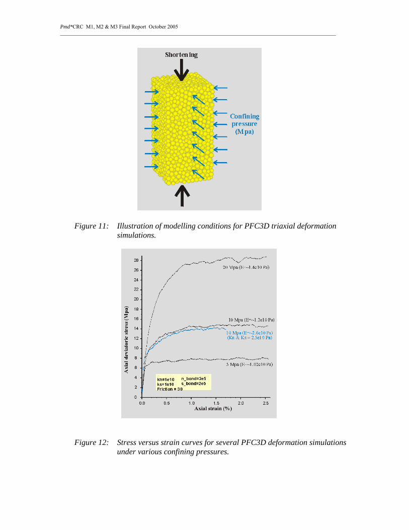
PFC3D (a three dimensional particle code) modelling has been carried out to explore the potential of the code in simulating the brittle behaviour and large strain features of rock deformation. The first effort is to perform numerical 3D triaxial deformation simulations (Fig. 1), similar to analogue triaxial rock deformation experiments, to establish a data base for a PFC rock library for use in future applications. This is a critical step because physical parameters used in particle codes do not simply correlate with the known properties of solid rocks.
Pmd*CRC M1, M2 & M3 Final Report October 2005 _______________________________________________________________________________________________________
Figure 11: Illustration of modelling conditions for PFC3D triaxial deformation simulations.
Figure 12: Stress versus strain curves for several PFC3D deformation simulations under various confining pressures.
Pmd*CRC M1, M2 & M3 Final Report October 2005 _______________________________________________________________________________________________________
The results obtained so far show that combinations of normal stiffness, shear stiffness, contact-bonding normal strength and shear strength, and friction coefficient determine the elastic parameters and plastic yielding features of an equivalent macro-material in a PFC3d bonding model. The stress-strain relations from these models in general are consistent with the elastic-plastic behaviours of rocks predicted by analogue experiments and conceptual theories (Figure 12), represented by an elastic loading segment followed by plastic yielding. The details of these features are also relevant to the confining mechanical pressure, the size of particles and distribution patterns, and the deformation loading rates. To validate this relationship for use in future application models, the present modelling effort is to numerically reproduce the results of classic physical deformation experiments for real rocks (Edmond & Paterson 1972).
PFC2D model: fracture development at a laboratory scale
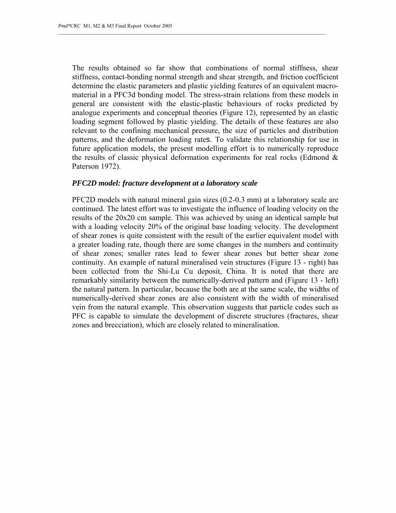
PFC2D models with natural mineral gain sizes (0.2-0.3 mm) at a laboratory scale are continued. The latest effort was to investigate the influence of loading velocity on the results of the 20x20 cm sample. This was achieved by using an identical sample but with a loading velocity 20% of the original base loading velocity. The development of shear zones is quite consistent with the result of the earlier equivalent model with a greater loading rate, though there are some changes in the numbers and continuity of shear zones; smaller rates lead to fewer shear zones but better shear zone continuity. An example of natural mineralised vein structures (Figure 13 - right) has been collected from the Shi-Lu Cu deposit, China. It is noted that there are remarkably similarity between the numerically-derived pattern and (Figure 13 - left) the natural pattern. In particular, because the both are at the same scale, the widths of numerically-derived shear zones are also consistent with the width of mineralised vein from the natural example. This observation suggests that particle codes such as PFC is capable to simulate the development of discrete structures (fractures, shear zones and brecciation), which are closely related to mineralisation.
Pmd*CRC M1, M2 & M3 Final Report October 2005 _______________________________________________________________________________________________________
Figure 13: Comparison between numerically-predicted shear zones (left) and natural Cu-mineralised vein structures from the Shi-Lu Cu deposit, Guangdong, China (right).
PFC2D model: fracture development at an outcrop scale
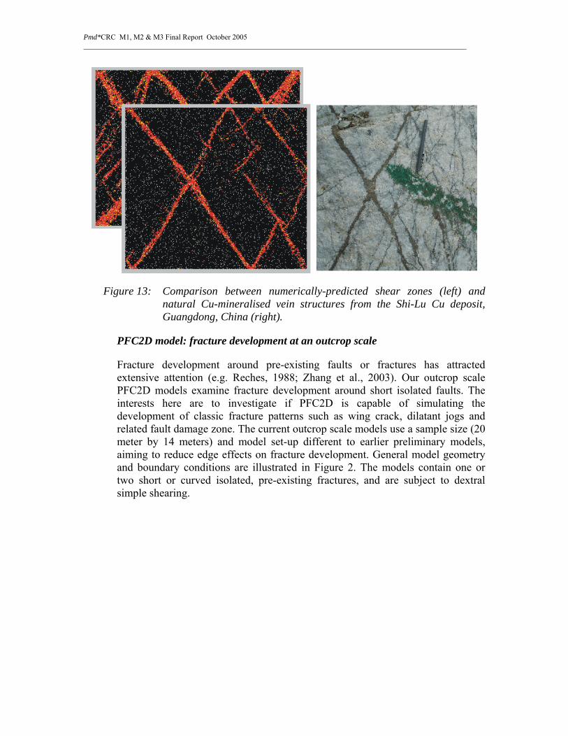
Fracture development around pre-existing faults or fractures has attracted extensive attention (e.g. Reches, 1988; Zhang et al., 2003). Our outcrop scale PFC2D models examine fracture development around short isolated faults. The interests here are to investigate if PFC2D is capable of simulating the development of classic fracture patterns such as wing crack, dilatant jogs and related fault damage zone. The current outcrop scale models use a sample size (20 meter by 14 meters) and model set-up different to earlier preliminary models, aiming to reduce edge effects on fracture development. General model geometry and boundary conditions are illustrated in Figure 2. The models contain one or two short or curved isolated, pre-existing fractures, and are subject to dextral simple shearing.

Pmd*CRC M1, M2 & M3 Final Report October 2005 _______________________________________________________________________________________________________
Figure 14: Model geometry and shearing boundary conditions.
As a result of dextral shearing of a model containing a short, pre-existing fracture (Figure 3, left), failure is localised near the tips of the pre-existing fracture (red - tensile failure, green-shear failure). This led to the development of cracks at the tips of the pre-existing fracture. The geometries of the cracks developed in the pfc2d models are consistent with the theoretical geometry of wing cracks, and also compare well with natural wing-cracks in deformed rocks (Figure 15, right).
Figure 15: Cracks developed in a pfc2d model (left) and a natural wing crack vein structure in deformed rocks (right, after Rispoly 1981).

Pmd*CRC M1, M2 & M3 Final Report October 2005 _______________________________________________________________________________________________________
Figure 16: A dilatant jog developed in a pfc2d model (top) and a natural dilatant jog vein structure in turbidites (bottom).
A series of models have been constructed to simulate fracture development in dilatant and contractional jog scenarios. The models show that dilatant spaces are always developed at the location of dilatant jogs, while ‘wing’ cracks develop at the other end of pre-existing fractures. The detailed geometries of the dilatant region are related to overlap of the two pre-existing fractures. Figure 16 (top) illustrates the geometry of the dilatant jog space developed in one pfc2d model, which display excellent similarity to the pattern of a dilatant jog vein structure formed in turbidites (Figure 16, bottom). In the contraction jog situation, there is no the development of dilatant space and there is a localisation of shear failure at the contraction segment of the pre-existing fractures.
Models have also been constructed to simulate the development of fractures and damage zones associated with an irregularly curved, pre-existing fractures. As is illustrated in Figure 17, there are several emerging structures, which can be characterized: 1) wing-crack type fractures at hinge point of curvatures; 2) dilatant space at dilatant segments; 3) shear failure damages at contraction site; 4) fracture truncation at low wavelength fracture curvatures.

Pmd*CRC M1, M2 & M3 Final Report October 2005 _______________________________________________________________________________________________________
Figure 17: Initial geometry of a pre-existing curved fracture in a pfc2d model (top) and fracture/damage patterns developed in the model after dextral shearing (bottom).
The development of discrete fractures and damage zones is compared with volumetric strain (volume increase or dilation) and fluid flow patterns in continuum FLAC models (Figure 18). It is noted that the geometries of dilatant spaces correlate well with volume increase (dilation) patterns from the continuum models, and fluids are clearly focused into dilatant site (out of contraction site). This explains why mineralisation often occurs at dilatant segments of fractures as shown in Figure 19.
Figure 18: Dilation (volume increase) patterns developed in a FLAC2D model (top) and fluid flow patterns in a small portion of the model (bottom).

Pmd*CRC M1, M2 & M3 Final Report October 2005 _______________________________________________________________________________________________________
Figure 19: Mineralised vein structures from the Shi-Lu Cu deposit, Guangdong, China.
4. FLAC3D-Gibbs coupling
Significant progress was made in coupling the Gibbs chemistry module with FLAC3D with the aim of allowing fully-coupled simulation of reactive fluid flow, heat transport, and deformation. The coupled code uses a particle tracking algorithm to transport aqueous components in the pore fluid {Fabriol, Sauty, et al. 1993 #910}. This method of calculating solute transport is faster than traditional finite difference or finite element schemes, because the transport equation is solved just once for each timestep. A further advantage of particle tracking over FE or FD methods is that it does not introduce numerical dispersion. Some interesting results were generated; these are fully documented on the Twiki. For example, Figure 19 shows the results of a 1D simulation of water flowing through a quartz rock with a temperature gradient. The observed evolution of the % volume of quartz is qualitatively correct, showing continuous dissolution by fluid flowing up a temperature gradient, and continuous precipitation by fluid flowing down a temperature gradient.
A set of tests (representing use cases relevant to the modelling requirements of AngloGold) were carried out (see https://pmd-twiki.arrc.csiro.au/view/Pmdcrc/ProjectM2Flac3DGibbsUseCases). Unfortunately, while the code does generate valid results on very simple examples, it is not sufficiently efficient to be useful on the more complex meshes and chemistries which are of interest to industry.

Pmd*CRC M1, M2 & M3 Final Report October 2005 _______________________________________________________________________________________________________
A B
Figure 19: Evolution of quartz due to fluid flow through a 1D column with a temperature gradient of +2°/m (A) and -2°/m (B). Darcy flux = 10-11 m3/m2/s.
Fully-coupled modelling with FLAC3D-Gibbs
The Flac3D-Gibbs code has been applied to a “fully-coupled” system, in which localised deformation results in focused fluid flow, leading to chemical changes as reactive transport takes place. Such coupling of mechanical, thermal, fluid, and chemical processes has never previously been achieved. The model is described in detail on the Twiki, page projectM2Flac3DgibbsFullyCoupled (PETRA PLEASE ADD IN THE TWIKI LINK). Speed and memory limitations restricted the model to a pseudo-2D system, with a weak “fault” embedded in stronger host rock (Figure 20). The system is being shortened in the x-direction, fixed in the y direction, fixed at the base and is free to deform at the top surface. Shear failure and dilation occur preferentially within the fault, resulting in permeability increase and focused fluid flow. The resulting chemical evolution is qualitatively correct (Figure 21), with little change in the concentration of quartz or gold except in and around the fault, where focused fluid flow takes place. The concentration patterns are somewhat uneven or patchy; the cause of this unevenness is unclear. Total run time was approximately 80 hours, but frequent and apparently random computer crashes resulted in an overall run time of 7 days. While the results of this simulation are encouraging, there is clearly more work to be done before this coupled code can be applied to real geological problems with realistic geometries (requiring many thousands of zones) and realistic (i.e. complex) chemical compositions.

Pmd*CRC M1, M2 & M3 Final Report October 2005 _______________________________________________________________________________________________________
Figure 20: Model geometry and boundary conditions
Quartz (mol/kg) Gold (mol/kg)
Figure 21: Precipitation/dissolution after 167 years
Testing of FLAC3D-Gibbs coupled code
Testing of the coupling between FLAC3D and HCh/Gibbs is largely complete and is fully documented on the TWiki. Heather Sheldon (CSIRO) worked closely with

Pmd*CRC M1, M2 & M3 Final Report October 2005 _______________________________________________________________________________________________________
Itasca to resolve the remaining issues with the code, which related mainly to the particle tracking method that is used for solute transport. Most issues have now been addressed; in particular, the particle tracking algorithm now works correctly on non-uniform meshes (at least to the extent that this has been tested), making the code usable for a much wider range of problems than was previously possible. Another key breakthrough was the discovery that water must be transported with the aqueous species in order to stabilise solute transport.
The usability of this code for real geological problems is limited by the amount of memory that is available to Windows applications, and by the speed of calculations. For example, a model with 32000 zones took 15 hours to complete 8 fluid flow + chemistry steps, and generated a virtual memory error within that time. This was with 10 particles per zone, which is unlikely to be sufficient to achieve an accurate solution. Doubling the number of particles caused the model to crash during the first equilibration step due to insufficient memory. Applicability of the code is therefore limited to 2D models with a few thousand zones, or 3D models with a very coarse mesh.
5. Multiscaling
“To develop a quantitative modelling system capable of multi- scaling”.
A very practical limitation to the simulation of mineralising scenarios in large systems is the very large range in length and time scales involved. Thus, if the system needs to be modelled at the litho spheric scale (200 km thick) then one commonly needs spatial resolution of less than 1 km at the (unknown) mineralising site. Equally, the system may take 30 million years to reach steady state whilst mineralisation only occupies a small fraction of that time. The system needs to be modelled at all scales because of the non-linear feedback relations existing at all (time and length) scales. This situation leads to untenable compute times, especially in 3D. Thus we need to develop methods of efficiently incorporating all scales. Such approaches involve some form of multiscaling.
Our objective is to implement a unified theory from grain size to plate tectonic scales. The theory should include brittle dilatancy, ductile dilatancy and the brittle - ductile transition. This mechanically based fully coupled deformation-permeability constitutional framework will be applied to laboratory experiments and extrapolated to field examples via standard computational toolkits that allow prediction of multiscale fault evolution, self-consistent shear band, fault, fault-network scaling lengths, and include a growing database of fundamental damaged rock properties.
The scientific strategy is to move from phenomenological laws (e. g. Coulomb plasticity) to laws derived from basic scaling quantities, obtain fault width independent of numerical mesh, develop a self-consistent brittle-ductile transition at litho spheric scale and thereby obtain constitutive equations that work at geological scales. This sets the groundwork for coupled chemical - thermal-mechanical modelling.

Pmd*CRC M1, M2 & M3 Final Report October 2005 _______________________________________________________________________________________________________
Its implementation builds on the M2 project on particle code calculations PFC triaxial (and biaxial rock experiments) for the small to meso-scale modelling (PFC rock library for Gosford Sandstone, Carrara Marble, Granite, graphitic shale, mafic, ultramafic rock etc). In Stage 2 of the Modelling Program, it will be updated for a novel damage mechanics approach in continuum calculations that develop the capability to do meso – to plate tectonics modelling. This part of the project will be done in cooperation with Vladimir Lyakhovsky at the University of Jerusalem.
a) Modelling unstable or stick-slip fault behaviour
In our modelling of mineralising systems to date, using the continuum code FLAC, we have represented the bulk behaviour of faults by zones with mechanical properties explored within the faults as well as within the bulk rock. However, another approach is to represent faults as discontinuities, and with fluid flow along these discontinuities, as in the distinct element code UDEC. In this case though, the bulk rock remains ‘dry’. In both cases, quasi-static behaviour is simulated. We are presently exploring incorporating unstable frictional behaviour into FLAC, with fully dynamic behaviour. At present, the rate- and state-dependant approach of Dieterich (1979, 1981), Ruina (1983), Rice and Ruina (1983), and Gu et al. (1984) has been implemented for a single interface between two blocks. Its functionality is being tested using this simple model, and being validated against Reinen’s (2000) results, as well as other published results, before being incorporated as the fault breaking through a seal. Coupling of fluid flow into this system will then need to be addressed, through considering how rate- and state-dependant behaviour for a single frictional sliding surface may be applied to bulk rock and/or through incorporating fluid flow along an interface. This will enable us to explore the influence of changing stress and deformation states associated with seismic events upon fluid flow characteristics. The results to date demonstrate that unstable, stick slip behaviour can be simulated even though the geometry of the classical spring-slider system is not included here. Comparison with recent work in this regard by Rice (2001) is being explored.
The conclusion of this work is that the classical application of rate and state dependent frictional constitutive laws has involved the instabilities developed between two sliding surfaces. In such a situation, the behaviour and evolution of asperities is the controlling mechanism of velocity weakening. However, most faults have a substantial thickness and it would appear that it is the bulk behaviour of the fault gouge, at whatever scale, that is important. The purpose of this paper is to explore how bulk frictional sliding behaviour may be described. We explore here the consequences of applying the rate and state framework initially developed to describe the frictional behaviour at the interface between two interacting sliding blocks, to frictional behaviour within a layer of gouge that has bulk elastic/plastic constitutive behaviour. The approach taken here is to replace the relative sliding velocity in the classical formulation with the maximum shear strain rate, D, and the characteristic length with a characteristic shear strain, γ c. This means that the frictional behaviour of the bulk material now evolves with shear strain rate, D, over a characteristic shear strain, γ c. This approach still does
Pmd*CRC M1, M2 & M3 Final Report October 2005 _______________________________________________________________________________________________________
not address the problem of reproducing natural recurrence times between instabilities, but perhaps places the problem in a new framework.
b) Damage mechanics
Damage mechanics is an alternative to the classical constitutive models (e.g. Mohr-Coulomb) for mechanical deformation of rocks. A major advantage of damage mechanics is the ability to predict strain hardening and softening during deformation, rather than imposing such behaviour on the model through an empirical relationship between rock properties and strain (as in the Mohr Coulomb approach). Furthermore, we anticipate that damage mechanics will be better able to predict features such as localisation, the width of faults or shear zones, dilatancy, and the transition from brittle to ductile behaviour within the lithosphere.
Heather Sheldon, Alison Ord and Klaus Regenauer-Lieb have made significant progress in the implementation of the damage mechanics formulation in FLAC3D. The model will be parameterised using results of PFC simulations, laboratory results, and field observations. Further information can be found on TWiki page ProjectM2DamageMechanics (PETRA PLEASE REPLACE THIS WITH THE TWIKI LINK).
Damage mechanics formulation for FLAC3D
Damage mechanics is an alternative to the classical Mohr-Coulomb constitutive model for mechanical deformation of rocks. Strain softening, non-linear elasticity, and stick-slip behaviour are incorporated into the damage mechanics formulation in a self-consistent manner, taking account of surface energy associated with the formation and healing of microcracks. This approach has been implemented in FLAC3D via the “user-defined model” (UDM) tool, which enables the user to modify any of the built-in stress strain relationships in FLAC3D. Preliminary results can be viewed on the Twiki (page ProjectM2DamageMechanicsF3Dtests) (PETRA PLEASE REPLACE THIS WITH THE TWIKI LINK). This work is based on an approach developed by Vladimir Lyakhovsky and co-workers. The next step is to compare the FLAC3D implementation with Lyakhovsky’s code (written in FORTRAN). Discrete element simulations performed using PFC3D may be used to parameterise the code.

Pmd*CRC M1, M2 & M3 Final Report October 2005 _______________________________________________________________________________________________________
Figure 22: Contour plot of shear strain after 7.19% shortening, showing localisation into shear bands.

Pmd*CRC M1, M2 & M3 Final Report October 2005 _______________________________________________________________________________________________________
6. Constitutive behaviours and the evolution of rheological properties within hydrothermal systems
a) Folding
Folds have inspired many people to explore the folding process, one objective being whether or not fold wavelength and amplitude may be predicted; a more risky objective being to infer the mechanical properties of the rock being folded from the observed wavelengths and amplitudes, with obvious application for the pmd*CRC. M. A. Biot published on this topic from the 1930’s through the 1960’s, and the topic was developed further from the 1980’s to the present by numerous people including B. E. Hobbs and co-workers (https://pmd-twiki.arrc.csiro.au/gnusave/Pmdcrc/HobbsMuhlhausOrdZhang).
The first aspect of the new work was to focus on the development of folds in anisotropic, viscous materials. Much of the previous, ‘classical’ work on folding has concentrated on isotropic, viscous materials. In such treatments, the folding is driven by strong contrasts in the viscosity, the resulting wavelength being a function of the viscosity contrast. One serious problem with the classical treatments is that folding only develops for viscosity contrasts of 100 or more. Such high viscosity contrasts are rare in nature. For low viscosity contrasts, the layers simply thicken with very little, if any, folding. A second problem is that only one wavelength is amplified (the Biot dominant wavelength) and the deflection is always strictly sinusoidal so that irregular or multi-wavelength folds (i.e. parasitic folds) are never predicted.
Once anisotropy is introduced, many aspects of these limitations are overcome. Folding is now driven by the anisotropy contrasts (i.e. contrasts in the layer parallel viscosity). Folds develop for very low anisotropy contrasts – as low as 10 – which is compatible with what is observed in natural folds. The first wavelength nucleated is less than the Bio dominant wavelength (again compatible with natural folds) and the system then progresses through a series of bifurcations with other wavelengths progressively growing. The incorporation of anisotropic viscosity into constitutive libraries is therefore an important aspect of being able to duplicate natural deformation patterns.
The more recent work has focussed on the influence of the migration of chemical constituents, driven by gradients in normal stress, upon the evolution of fold geometry in anisotropic, linearly-viscous, multi-layered materials. Some aspects of ‘remobilisation’ in hydrothermal systems may be modelled through such work.
The resulting model for finely layered visco-elastic rock was then further developed and made more general. Discussions with Scott Paterson at the magmatic processes workshop resulted in a PhD student, Luke Jensen, visiting us for 2 weeks in June/July to work on this topic. The work in this project has formulated this work in a manner suitable for implementation within FLAC3D.
Pmd*CRC M1, M2 & M3 Final Report October 2005 _______________________________________________________________________________________________________
This is the first time we have developed such a ‘user-defined constitutive model’ so that we have developed our skills in this area as well as made the anisotropic viscosity model more accessible for application.
The first version of the Anisotropic Viscosity Constitutive Model written in C++ has been developed, with the functionality accessible to FLAC3D users. The model has been tested using examples with a simple geometry. To test the Anisotropic Viscosity Constitutive Model functionality a one zone cube model has been created and tested for different shearing scenarios, to check its results against predictions such as the orientation of the normal to the foliation during shearing in known directions. Cooperation in creating and testing above examples between potential users (conceptual modeller) and developers (mathematical and numerical modeller) provided a better understanding of the nature of the problem from geological, geometrical and numerical point of view as well. The model will be now tested for real geological scenarios. (PETRA PLEASE CHECK TO SEE IF THERE IS ANY OTHER TWIKI LINK FOR THIS WORK OTHER THAN THE LINK PROVIDED ABOVE - HEATHER MIGHT KNOW)
b) Constitutive relationships
Regan Patton joined the project team late in the life of the project. His focus is on developing a rigorous understanding of the mechanical concept of Second Order Fluids, developed by Coleman and Noll in the 1960’s. Such fluids appear to be capable of representing a very wide range of behaviour including plastic failure, localization, creep and more complicated viscoelastic behaviour. Since he joined the team, he has been focussing on writing up his work for a manuscript designed to be comprehensible to geologists. As milestones along the way, he has been developing brief notes, of which the following is a particularly useful and illuminating example.
More than ‘power law’: some quotes
From Hobbs [1972]…
“…[F]luids in which the stress is a nonlinear function of the instantaneous rate of deformation …are called Reiner-Rivlin fluids, and examples, when properly formulated, are the ‘power laws’ observed for steady-state creep of polycrystalline aggregates.”
“It is clear that these power laws are intended to represent only steady-state creep and that [the Reiner-Rivlin equation] cannot represent the complete mechanical behaviour of polycrystalline aggregates in general deformations.”
“An important experimental point is that in a steady-state shortening experiment all simple fluids behave as Reiner-Rivlin fluids, so that it is impossible to

Pmd*CRC M1, M2 & M3 Final Report October 2005 _______________________________________________________________________________________________________
distinguish between these [and more complex materials] by this type of experiment. Such experiments cannot provide enough information to predict the behaviour of simple fluids in deformations with other geometries, such as simple shear, folding, of convective motion.”
From Hobbs, Means, and Williams [1976]…
“On the atomic scale, a dislocation represents a linear region in which atoms are not quite in their proper crystallographic positions; that is, the atomic arrangement has been elastically distorted. The direction of slip in any particular slip plane is generally parallel to the closest-packed direction, since this tends to minimize the elastic distortion associated with the dislocation core. This distortion has associated with it a stress field that can exert forces on neighbouring dislocations or other defects. The elastic distortion also means that there is strain energy associated with a dislocation so that the introduction of dislocations increased the free energy of the crystal. Dislocations are, therefore, unstable defects, and if a crystal with dislocations is heated, the dislocation density will decrease; for all practical purposes, the equilibrium concentration of dislocations in a crystal at a particular temperature is zero.”
From Rundle and Passman [1982]…
“The appropriate relationship between stress and deformation, or “constitutive model” as it is commonly termed, is a subject of great debate in geophysics. The advocates of a nonlinear relation between stress and strain rate point to a profusion of triaxial data for their rationale.”
“An assumption often made when interpreting results from triaxial experiments is that strain rate and rate of deformation (symmetric part of the velocity gradient) are interchangeable quantities. In fact these two quantities have different behaviours under changes of frame. It appears from the literature that most authors do replace the strain rate tensor in constitutive models found from triaxial experiments with the rate of deformation tensor when doing computations at finite strain. However, it is rarely recognized that that this is a valid procedure only at vanishing strain.”
“The [power law] form of the stress-deformation relation often seen in triaxial experiments is often explained as being the result of intragranular dislocation motion (e.g., Weertman and Weertman, 1975). Additionally, it is sometimes asserted that constitutive models with a linear relation between stress and deformation cannot explain the experimental data. … [However, a] suitably complicated linear model can be used to model such a data set. We do not mean to imply that dislocations are unimportant in creep deformation. Indeed, it is quite obvious from post-experiment examination of creep samples that dislocation densities and configurations often change radically during the test. However, the effects of dislocation motion may not be as direct as is usually assumed; dislocation motions during the test cannot, after all, be directly observed.”

Pmd*CRC M1, M2 & M3 Final Report October 2005 _______________________________________________________________________________________________________
“Although to our knowledge no tests have been done on geologic materials on geologic time scales, extensive testing of other fluids has been done. To our knowledge, not a single fluid has ever been found with zero normal stresses except for those with constant shear viscosity. This does not have the status of a proved theorem, but it is an experimental result of apparently universal validity. In these cases if nonlinearity appears, it appears both in the shear and normal stress terms.”
“No Reiner-Rivlin fluid has ever been found in nature. The simplest fluid exhibiting normal stress effects in a viscometric flow is the fluid of grade two [i.e., second order fluid]. It is widely accepted in polymer rheology as a physically appropriate first approximation for fluids with non-linear viscosity.”
“Let us conceive of a set of experiments in which we search for the effects of nonlinear viscosity at increasingly higher shear rates. We would find that the nonlinearity in the normal stress appears when the shear rate squared becomes significant in size, while the nonlinearity in the shear stress does not appear until the shear rate is larger. Thus the existence of normal stress effects will be observed before the shear stress departs from a linear dependence on shearing.”
“The experimental determination of constitutive equations must be handled with considerably more care than has usually been the case in geophysics. In the case of steady extension, for example, the test is so restricted kinematically that it gives the same results for a wide variety of materials. Power-law behaviour is a special case of these results, and is not a property of the material, but rather an unavoidable consequence of the particular test and assumed mathematical smoothness. On the other hand, if there is some a priori reason for expecting nonlinearity in the stress-deformation relation, normal-stress effects are an unavoidable consequence of that nonlinearity and appropriate representation theorems.”
From Joseph [1989]…
“The [retarded motion] expansions [leading to the second order fluid] were introduced by Coleman and Noll [1960] and they were justified in the context of their theory of fading memory. These expansions are robust in the sense that they carry over to more general theories, which contain most of the constitutive equations presently used by rheologists. The form which such expansions must take is strongly suggested in the theory of Rivlin and Ericksen [1955].”
“[The Reiner-Rivlin equation] is not presently used in rheology because it has a zero first normal stress in shear flow. On the other hand, every constitutive equation can be expressed by [the Reiner-Rivlin equation] in steady motions which are purely extensional since the history of such motions can be expressed in terms of A
(1) alone.”

Pmd*CRC M1, M2 & M3 Final Report October 2005 _______________________________________________________________________________________________________
Sub-project M2.2 - Quantitative modelling of magmatic processes – emplacement, thermal effects, and fluid generation
“To develop a quantitative modelling system capable of realistically simulating magmatic processes, including emplacement, thermal effects, and fluid generation”.
Efforts on this sub-project were suspended mid-way through the M2 project at the behest of the CRC’s Executive Research Committee; it was felt that there were insufficient resources in the Program to do this research area justice. Nonetheless, prior to this decision being made, a number of activities were undertaken.
A magmatic processes workshop was held from 17 to 20 March, 2003 at the CSIRO offices in Perth (the ARRC). It was entitled, Processes Involved in Magma Intrusion and Volatile Segregation, with topics including:
1. Melt segregation mechanisms in regions of partial melting of the lithosphere.
2. Melt transport mechanisms in the lithosphere.
3. Architectural and dynamic controls on modes of emplacement of magmatic bodies.
4. Mechanisms for generating heat to initiate melting in the lithosphere.
5. Fracture generation during igneous intrusion.
6. Fluid production (brines, vapours, melts) in cooling igneous intrusions.
7. Mechanisms of fluid transport away from cooling igneous intrusions.
8. The composition of volatiles within cooling igneous intrusions.
9. Evolution of fluid composition during transport away from igneous intrusions.
10. The physics and chemistry of melting and volatile generation.
11. Mechanisms of sulphur production and precipitation in and around cooling igneous intrusions.
The aim of this sub-project was to stimulate the development of computer codes that will enable key processes of magma intrusion and volatile segregation to be modelled and to be incorporated into mineral exploration scenarios. This workshop was aimed at facilitating this process. To this end, it was proposed that each participant in the workshop present a one hour paper on a particular facet of the problem with the specific view of detailing the processes involved. The challenge here was to present these topics

Pmd*CRC M1, M2 & M3 Final Report October 2005 _______________________________________________________________________________________________________
in a quantitative manner that would be amenable to subsequent incorporation into computer codes.
We enticed some excellent scientists to join us, including from the ETH, Zurich, Chris Heinrich (out of his holidays for one day), Jamie Connolly and Klaus Regenauer-Lieb; from the USA Mike Brown (University of Maryland), Sue Kay (Cornell University), Scott Paterson (University of Southern California; and from elsewhere in the world Jorge Skarmeta (CODELCO, Chile), Nick Fox and Abhen Pather (AngloGold, Johannesburg), Peter Cundall (ITASCA, Minnesota); from elsewhere in Australia Ron Vernon (Macquarie University), Douglas Haynes, Mike Sandiford and David Hansen (University of Melbourne), Nick Oliver, Tim Baker and James Cleverley (James Cook University); and from Perth Bruce Hobbs, Scott Halley (Placer Dome Asia Pacific) and Gem Midgley (AngloGold), as well as CSIRO participants Chongbin Zhao, Ernst Kohler, John Walshe, Paul Roberts, Peter Hornby, Rob Woodcock, Klaus Gessner, Peter Alt-Epping and Alison Ord.
Associated documents and presentations (including movies) were uploaded into https://twiki.arrc.csiro.au/view/Magma/WebHome so as to allow access to non-pmd*CRC participants. Summary documents are included for discussion groups Industry, Academia, and the Mathematical/Numerical world. These form the basis for the development of the way forward.
Numerical Modelling Activities
Due to the complicated and complexity nature of the magma intrusion problem within the crust of the Earth, it is useful to conduct numerical simulation of this kind of problem progressively from a low level stage into a high level stage. This research methodology is rational because of the multiple time and length scales of the problem itself. Thus, we plan to solve the magma intrusion problem using the following three level models.
• For the first level model, we primarily consider the effects of the post-solidification magma on the pore-fluid flow, heat transfer and ore forming patterns within the upper crust of the Earth.
• For the second level model, we consider the effects of the post-intrusion but pre-solidification magma on the pore-fluid flow, heat transfer and ore forming patterns within the upper crust of the Earth. In this model, we must develop some useful and efficient computer algorithms to simulate the magma solidification problem.
• For the third level model, we will consider the intrusion process itself in a much smaller scale using the particle mechanics based computer algorithms such as those used in PFC codes. Once the efficient numerical algorithms for dealing with above three level models are developed, it is possible to integrate them together to simulate the whole process of the magma intrusion problem.
First level model
Pmd*CRC M1, M2 & M3 Final Report October 2005 _______________________________________________________________________________________________________
A paper entitled "Effects of hot intrusion on pore-fluid flow and heat transfer in fluid-saturated rocks” was prepared for possible publication, an extract of which follows:
"We use the finite element method to solve coupled problems between pore-fluid flow and heat transfer in fluid-saturated porous rocks. In particular, we investigate the effects of both the hot pluton intrusion and topographically driven horizontal flow on the distributions of the pore-flow velocity and temperature in large-scale hydrothermal systems. Since general mineralization patterns are strongly dependent on distributions of both the pore-fluid velocity and temperature fields, the modern mineralization theory has been used to predict the general mineralization patterns in several realistic hydrothermal systems. The related numerical results have demonstrated that:
• The existence of a hot intrusion can cause an increase in the maximum value of the pore-fluid velocity in the hydrothermal system.
• The permeability of an intruded pluton is one of the sensitive parameters to control the pore-fluid flow, heat transfer and ore body formation in hydrothermal systems.
• The maximum value of the pore-fluid velocity increases when the bottom temperature of the hydrothermal system is increased.
• The topographically driven flow has significant effects on the pore-fluid flow, temperature distribution and precipitation pattern of minerals in hydrothermal systems.
• The size of the computational domain may have some effects on the pore-fluid flow and heat transfer, indicating that the size of a hydrothermal system may affect the pore-fluid flow and heat transfer within the system."
Second level model
A paper entitled "An equivalent algorithm for simulating thermal effects of magma intrusion problems in porous rocks” was published in the journal of Computer Methods in Applied Mechanics and Engineering, an extract of which follows:
“An equivalent algorithm is proposed to simulate thermal effects of the magma intrusion in geological systems, which are composed of porous rocks. Based on the physical and mathematical equivalence, the original magma solidification problem with a moving boundary between the rock and intruded magma is transformed into a new problem without the moving boundary but with a physically equivalent heat source. From the analysis of an ideal solidification model, the physically equivalent heat source has been determined in this paper. The major advantage in using the proposed equivalent algorithm is that the fixed finite element mesh with a variable integration time step can be employed to simulate the thermal effect of the intruded magma solidification using the conventional finite element method. The related

Pmd*CRC M1, M2 & M3 Final Report October 2005 _______________________________________________________________________________________________________
numerical results have demonstrated the correctness and usefulness of the proposed equivalent algorithm for simulating the thermal effect of the intruded magma solidification in geological systems.”
Students
Chris Wijns obtained a PhD (with Distinction) during Stage 1 of the CRC. He was also involved with applications of Fabio Boschetti's interactive inversion technology. Together with Placer Dome Exploration's chief geophysicist in Vancouver, Canada, Chris also trialled the joint inversion of geophysical data by both numerical and interactive methods. The numerical inversion is the traditional part, and uses the UBC 2D inversion code for induced polarisation (IP) data. The interactive component allows humans to select geological desirable targets from a range of geophysically allowable results. The different inversion results are the product of different inversion parameters, such as model smoothness, data misfit, the reference model, etc.
John McLellan's PhD project was on Numerical Modelling of Deformation and Fluid Flow in Hydrothermal Systems. Recent work has been examining the effect of topography and extensional deformation on fluid flow with an application to Hamersley Iron Ores (see Publication McLellan et al, 2003) using FLAC. During early stages of extension and collapse of a mountain range there is competition between upward and downward flow within more permeable structures such as shear zones/faults. As extension progresses downward flow within the fault becomes more prominent. Lateral fluid flow can be identified in Banded Iron Formation (BIF) layers with potential fluid mixing sites at and around the fault-BIF contacts. The addition of a permeability enhancement function to simulate silica dissolution enables stronger lateral fluid flow within the BIF layers. This research has highlighted areas of potential exploration for further iron ore deposits in the region.
Julia Blockeel, an MSc student from the Cambourne School of Mines (UK), joined the Computational Geoscience group at CSIRO in May to work on her MSc research project. Her research focused on the association between intrusions, convection and the metamorphic facies distribution around Kalgoorlie. This work expands on a preliminary “proof of concept” investigation, which showed that convection can create cold regions due to downwelling fluids in a convection cells associated with local heat sources in the crust. Refer to https://pmd-twiki.arrc.csiro.au/twiki/bin/view/Pmdcrc/ModellingYnew for further details. Julia is the first such student to be supported by IVEC (the WA node of APAC - Interactive Virtual Environment Centre), as well as by the pmd*CRC (in kind).
ELFEN testing
ELFEN is a finite element code with 2D and 3D modelling capability, implicit and explicit solver options, and reasonable graphics (post processing) functionality. The intent was to test and explore the capabilities of the code, and to allow for general discussion and comparison with other codes, including at least FLAC.

Pmd*CRC M1, M2 & M3 Final Report October 2005 _______________________________________________________________________________________________________
CSIRO personnel were involved in several phases of code testing. Yanhua Zhang tested ELFEN on various test problems (in part with John McLellan of James Cook University). In addition, Warren Potma provided the following comments on his two days of exploring the code with Klaus Gessner:
“Positives: Obviously the ability to model brittle fracture is a very large positive. • The materials properties database within ELFEN is a very good concept. It
appears to be easily customizable and updatable with new rock properties etc as they are created.
• Model geometry setup and mesh generation in ELFEN seems fairly flexible and intuitive. Much of the process can be mouse driven and/or x,y,z co-ords can be used The manual describes the methodology for the creation of both structured and unstructured meshes relatively simply and there are many tools available for shape generation (arc & circle tools etc) In this sense I think the setup of the model geometry may be simpler and much more user friendly than FLAC.
• The assignment of material properties is fairly straight forward although the presence of default values in most fields can lead to the "black box syndrome".
• Visualisation of results is achieved simply through the point and click GUI (much easier and more intuitive than FLAC; at least the command line version) Negatives:
• In general the GUI sets defaults for each field at every stage of the model setup process. I feel that this is very dangerous for the semi-trained user. This danger is compounded by the manual suggesting that many of the defaults should just be "accepted".
• The modelling constraints and boundary features data entry screens have many options that are not intuitive & are not well documented often resulting in the selection of the default option.
• The modelling Control menu is a real "Black Box" containing multiple selections that must be made, many of which are very poorly documented. Among these is the iteration scheme for which about 8 schemes are offered and none are documented as to their effects.
• The manual talks about the use of model steps and time steps yet one is often forced to use time increments even if steps are warranted.
• The concept of "convergence" and its implications for the modelling process are not well documented yet they appear/are pivotal to the output of the model.
• Setting up the model loading functions (eg applying velocities, gravity, displacements etc) is quite difficult to understand.

Pmd*CRC M1, M2 & M3 Final Report October 2005 _______________________________________________________________________________________________________
Judging by the progress Klaus and I made on day two, I feel that many of our initial reservations may be overcome by further use and familiarity with ELFEN. The GUI became more tolerable with time but I think it imposes an unnecessary inflexibility on the high end user. Unfortunately the nature of the .dat files, mean that back end programming is almost out of the question as much of the code is cryptic.
Discussions were also held between Geoff Loughran, a director of Rockfield, and Nick Oliver, Paul Roberts, Peter Hornby and Alison Ord to discuss how ELFEN might progress within the pmd*CRC.
All ELFEN related material may be accessed under
https://twiki.arrc.csiro.au/view/Pmdcrc/ELFEN.

Pmd*CRC M1, M2 & M3 Final Report October 2005 _______________________________________________________________________________________________________
Project M3 - Applications of Numerical Modelling Project Leader – Paul Roberts
Introduction
The visionary goal of this project (from the M3 CRC project agreement) is:
“To develop systems and expertise in the use of numerical modelling technology to enable industry and government clients to evaluate potential and explore prospective locations (at all scales) for large high value ore bodies far more efficiently than they can do now.”
This project was established to act as an interface between the numerical modelling developments in projects M1 and M2 and the external world – in both the mining industry and the universities. Therefore the project contained three main components:
1. Application of modelling to specific mineralisation-related problems which were not being funded by the terrane budgets but with results which could be open to all CRC sponsors, hence Sub-project M3.1 Non-Terrane Modelling Projects.
2. Development of simple computational tools (“templates”) which would enable much more efficient mesh building and therefore could facilitate uptake of the numerical modelling both by industry and students, hence Sub-project M3.2 Template Development.
3. Educational and training materials and courses for both geology students and industry, hence Sub-project M3.3 Modelling Library and Sub-project M3.4 Template Development.
Cash funding from the project came both from the pmd*CRC directly and the WA State Government. The latter were matching funds provided because a substantial part of the CRC operates within the State. They were provided under the auspices of a small “virtual” centre called the Earth System Modelling Group (see below). The latter’s primary purpose was (and is) to facilitate collaboration between UWA and CSIRO in the modelling area; the funds were provided to cover the salaries of two personnel, one at UWA and the other at CSIRO Exploration and Mining in Perth.
Earth System Modelling (“ESMG”)
There was some difficulty in establishing this collaborative venture mainly because of long delays in receipt of the funding and hence recruitment of personnel. The relevant State Government agency, the Office of Science and Innovation, was transferred to the Department of Premier and Cabinet in 2002 and funding approval was held up for about one year. In the meantime, the proposed nominee for the UWA-based ESMG Leader position, Dr Roberto Weinberg, was offered a permanent position at Monash University

Pmd*CRC M1, M2 & M3 Final Report October 2005 _______________________________________________________________________________________________________
in Victoria, which he took up in January 2003. He did, however, operate in the role for the previous 6 months on a temporary basis.
After Dr Weinberg’s departure, there was a long delay in finding a replacement. The position was advertised twice; the first round of advertising yielded only one viable candidate who subsequently declined the job offer. The second round resulted eventually in the appointment of Dr Klaus Gessner, who took up the position in July 2004. The CSIRO position was filled by Warren Potma, an ex-industry structural geologist, in October 2002.
Non-Terrane Modelling Projects
The sub-project strategy was to focus application at the ore system scale on projects that could demonstrate the methodology and value of applying numerical modelling to industry sponsors of the CRC. At first, the intention was to focus modelling work on projects outside of the CRC-nominated terranes. The focus changed to projects within them, however, after the first CRC Review meeting in December 2002.
Shui Kou Shan
This first activity was entitled: "Application of the coupled quantitative computational technology to mineral exploration in the Shui-Kou-Shan mineralisation district, Hunan Province, China". It was selected because the lead CSIRO researcher, Dr Yanhua Zhang had already been successful in winning $35,000 in funding from the Australia-China Special Fund for Scientific and Technological Cooperation (part of the Commonwealth Government’s Innovation Access program.) to cover travel and accommodation costs. Therefore, it represented a relatively simple and low cost start to this sub-project. It commenced in mid-2002 and was completed by early 2003.
The project involved cooperation with the CAS Changsha Institute of Geotectonics. Modelling was conducted at two scales – the regional scale (by Chinese research collaborator, Dr Ge Lin) and the mine scale by Dr Zhang. The latter work was focused on understanding the formation of polymetallic mineralisation at the Kang Jia Wan ore deposit. Dr Zhang carried out FLAC modelling of the ore system, and also experimented with another code, ELFEN, specifically in order to understand fracture formation in that ore body.

Pmd*CRC M1, M2 & M3 Final Report October 2005 _______________________________________________________________________________________________________
Figure 23: Cross section P104 – Kang Jia Wan Mine (drill holes are approximately 1000m long)
Profile 104
unconformity
F22 faultc
Ore bodies Silicified zone
Dr Zhang’s research showed that new permeability development is localized predominantly at fold hinges and in a silicified zone in the top of a Permian limestone unit. This process resulted in increased flow velocities and facilitated fluid focusing. The deposit scale cross-section models (Figure 24 below) reproduce the known patterns of tensile failure, permeability creation, fluid focusing and mixing, and fracture development. The implication is that the best brecciation locations in the district – and hence the best mineralization locations - should have two major characteristics:
1. a combination of fold hinge and limb locations (structural) and
2. the silicified zone and limestone unit (lithological).

Pmd*CRC M1, M2 & M3 Final Report October 2005 _______________________________________________________________________________________________________
Figure 24: Kang Jia Wan cross section P104 restored back to the time of mineralisation: (a) permeability and fluid flow in FLAC (above); (b) fracture development in ELFEN (below). Note that maximum fracturing is in the red silicified horizon.
Details of the Shui Kou Shan work may be found at https://pmd-twiki.arrc.csiro.au/twiki/pub/Pmdcrc/ProjectM3/sks_TechReport_final.doc
Wallaby
The Wallaby mine is wholly owned by Placer Dome Inc and is located in the Laverton District of Western Australia. CRC efforts there commenced in mid-2002 when an MSc student from the Camborne School of Mines, Matthew Rovardi, undertook a pilot modelling study using FLAC2D. During the December 2002 CRC review, Greg Hall of

Pmd*CRC M1, M2 & M3 Final Report October 2005 _______________________________________________________________________________________________________
Placer Dome offered access to the mine for a more substantial effort, following which a series of deformation and fluid flow modelling exercises were carried out.
Warren Potma commenced FLAC2D modelling in March 2003 following a site visit. The project objectives were to:
• Use numerical modelling to assist in targeting a deep DDH below Thets Fault.
• Continue development of Wallaby FLAC2D models, including:
o regional & deposit scale models
o explore more complex geometries
o better define the effects of different rock & deformation/fluid flow parameters on model behaviour.
• Develop FLAC3D model geometries both at the deposit scale and regional scale, to model the influence of basement structures and the 3D geodynamics of the deposit.
• Attempt to characterise the likely controls on high grade Au deposition and their relative importance (fluid mixing, fluid-rock interaction/sulphidation, phase separation).
The initial work was aimed at reproducing and understanding Rovardi’s results. A large series of FLAC2D tests were run on two models, one just a little larger than the mine environment itself and a second encompassing the sub-Thets Fault geology as well. The work then progressed to FLAC3D modelling at a scale encompassing the whole of the mineral system. In addition, Wallaby was used as a testbed for analysis and application of the inversion in geology methodologies being developed in project M1 and for early template development. Results and conclusions from all of this work included:
• The rheology contrast between strong syenites plus surrounding actinolite-magnetite alteration and weaker, less altered (or unaltered) basaltic conglomerates was a critical control on tensional failure development in the stronger rocks.
• Reproduction of the rock failure patterns, particularly the concentration of flat tensional fractures within the magnetite-actinolite alteration pipe and syenite, as observed in the ore deposit, is possible with very small amounts of bulk shortening (see Figure 25), consistent with field observations.
• Both 3D modelling and structural observations indicated that the mineralised system probably formed when the maximum compressive stress was oriented approximately north-south, rather than east-west (the initial supposition).
• Fluid modelling indicated a possible fluid mixing mechanism in which an ambient fluid in the basaltic conglomerate might mix with a deeper fluid which enters via the syenite margins. In this model the maximum chemical gradients would probably be

Pmd*CRC M1, M2 & M3 Final Report October 2005 _______________________________________________________________________________________________________
found at the edges of the alteration pipe. It may be relevant that gold grades tend to be higher towards the pipe margins although lode structures also tend to be thinner in the same area.
• A spatial coincidence between shear failure in the surrounding weaker rocks and active tensile failure within the alteration pipe may indicate a localisation mechanism for tensile failure which could be relevant for exploration (see Figure 25)
• Modelling predicted that there needed to be near-vertical continuous fluid conduits to enable stacked ladder vein formation. Subsequent mapping by John Miller (of Melbourne University) identified such structures.
• In order to test the efficiency of inversion on parameter search, an exercise involving 4 different input parameters with 8 variables for each parameter was carried out within FLAC2D. The exercise resulted in the creation and analysis of 4096 different model runs so that the full parameter space might be characterised. These results were then ranked with respect to each other and compared with an application of the inversion tool. This is the first time that the geological inversion tool was applied to a complex “real world” geological scenario. Multiple geological inversion runs were simulated using the same parameters as those used in the exhaustive search. The results of these inversion runs indicated that the inversion process converged on the optimal model parameters in ~100 model runs, a 40 times efficiency gain.
Most of the project objectives were achieved with the principal exception of assistance with targeting the planned deep drill hole. The issue here is that there are various interpretative possibilities in the sub-Thets Fault geology, all of which need to be tested with modelling to identify the most likely locations for new mineralisation. In the end, other project priorities prevented completion of the extensive parameter exploration required to achieve this goal. Despite this, the conclusion that only low bulk shortening is required to produce the required dilation tends to suggest that there will be very little offset beneath Thets Fault.
Details of the Wallaby work may be found at place https://pmd-twiki.arrc.csiro.au/twiki/bin/view/Pmdcrc/ProjectM3#M3_Wallaby_Gold_Mine_Numerical_M.

Pmd*CRC M1, M2 & M3 Final Report October 2005 _______________________________________________________________________________________________________
Figure 25: Wallaby model cross section. North is to the left. Approximately 2 km high. Yellow lines indicate active failure in tension within the syenite and magnetite-actinolite alteration and red-brown areas active failure in shear at the moment when this snapshot was taken.
Template applications
The template developments described in more detail below were used for preliminary investigation of several Yilgarn problems i.e. ramp flat geometries (e.g. at. Sunrise Dam; see Figure 26) and curved faults in contacting with a through-going structure (i.e. at Kanowna Belle; see Figure 27).
Other areas
M3 project modellers made contributions through various regional scale numerical modelling efforts in the Yilgarn and Isa terranes. Results of this work have been documented in various terrane reports, to which the reader is referred.
M3 project funds were also used to investigate other “open” modelling possibilities for the CRC in Australia, like the Tasmanides and the Central Gawler Gold province. The latter resulted in development of a project with PIRSA, which is now in progress. It aims to identify the possible geological characteristics of a high grade 5 million oz gold deposit in that province, in which only relative low grade (e.g. Tunkillia) or relatively high grade but low tonnage (e.g. Tarcoola) gold mineralisation has been found to date. The project proposal was developed in a three day workshop at the PIRSA offices in

Pmd*CRC M1, M2 & M3 Final Report October 2005 _______________________________________________________________________________________________________
Adelaide involving PIRSA personnel and researchers from GA, the University of Adelaide and CSIRO.
Figure 26: Fluid flow vectors (warm colours signify larger magnitudes) in ramp-flat FLAC3D template model

Pmd*CRC M1, M2 & M3 Final Report October 2005 _______________________________________________________________________________________________________
Figure 27: Fluid flow vectors (warm colours signify larger magnitudes) in curved fault FLAC3D template model
Exploration Modelling Template Development
The initial idea was to develop templates which could be provided to industry personnel via a web browser so that they could test their ideas without the on-site assistance of an expert modeller. This proved to be an impractical idea as the degree of sophistication required within the template to enable the non-expert user to get real value out of the tool would have required more programming resources than the funding would permit. So, the focus changed to developing computational tools that would:
• permit expert users to explore geometric variations easily in relatively simple models without time consuming efforts on mesh building;
• provide a helpful teaching tool to introduce postgraduate students to the use of deformation and fluid flow models, specifically with FLAC3D.
The resultant “products” are a series of control files in which easily-made changes to various parameters enable instantaneous rebuilding of the finite element mesh with changed (and computationally workable) geometries and rock properties. The latter can then be used immediately for FLAC runs. This has proved of immense value as

Pmd*CRC M1, M2 & M3 Final Report October 2005 _______________________________________________________________________________________________________
experiments on the differences in deformation and fluid flow behaviour patterns resulting from changing parameters can now be undertaken much faster on a wide range of practical problems.
This work involved the joint efforts of Warren Potma and applied mathematician, Thomas Poulet, from the M1 team. They produced a series of 2D and 3D templates which were used for:
• Application in this project (see previous report section),
• The Kundana project with Placer Dome,
• Two PhD projects and
• As a teaching aid in two MSc-level short courses.
A 2D template of the Wallaby cross section was the first developed (Figure 28). A series of 3D templates were then produced to help understand dilation and fluid flow in a variety of structural situations, e.g.:
• Ramp-flat geometries (Figure 26), which generated results which explained grade distribution patterns in the low angle lode sets at Wallaby.
• Curved faults terminating against a straight fault cf. Kanowna Belle (Figure 27). This geometry became possible once Bezier curves were introduced into the template control files.
• A variety of fault intersection problems cf. Kundana (see Figure 30). The latter were suggested by Scott Halley from Placer Dome and have proved to be of great value subsequently.

Pmd*CRC M1, M2 & M3 Final Report October 2005 _______________________________________________________________________________________________________
Figure 28: The first FLAC2D template – Wallaby in a N-S oriented cross-section (note: Thets Fault can be switched “on” or “off”)
These templates can be further manipulated to even produce intrusion shaped bodies (see below).
Figure 29 Shape variations possible from a single template

Pmd*CRC M1, M2 & M3 Final Report October 2005 _______________________________________________________________________________________________________
Modelling generic fault geometries
Figure 30: Kundana template, illustrating the intersecting fault zones recognised in the Kundana gold field
Use of the templates as part of the CRC’s education and training program commenced in late 2004. Michelle Stark, a PhD student from James Cook University visited the CSIRO offices in the last quarter of 2004 and Ivo Vos, a PhD student from Melbourne University, visited in the first quarter of 2005. Both managed to obtain a useful set of modelling results using FLAC3D templates in the space of about three weeks, something that was simply impossible previously.
In March 2005, John McLellan from James Cook University visited at CSIRO to acquire some training in the application of FLAC3D and use of the templates. This led to development of some useful teaching material both for the April MSc course at James Cook University as well as for the MSc course at the University of Western Australia in July.
Details of all the template developments can be found at https://pmd-twiki.arrc.csiro.au/twiki/bin/view/Pmdcrc/GenericModellingM3
Modelling Library
The modelling library developments took place in two bursts of activity – the first in the second half of calendar 2002 and the second part during 2003. The initial effort was almost entirely the work of Roberto Weinberg prior to his departure to Monash University. He developed a website using Dreamweaver in which he incorporated results from a number of pre-existing CSIRO projects. He also undertake some numerical
Internal Box Faults
F1 fault thickness = 50m
F2 fault thickness = 50m
Faults are weaker & more permeable than the
External Buffer 200m
2000m
2000m 3000m

Pmd*CRC M1, M2 & M3 Final Report October 2005 _______________________________________________________________________________________________________
modelling experiments, prepared textbook level information on aspects of mechanics and the science of earth process modelling. A snapshot from the initial website is provided in Figure 31.
Figure 31: Snapshot from first version of the Modelling Library authored by Roberto Weinberg
In November, 2002, a “living poster” was developed by Warren Potma as a way of displaying modelling library content as a type of extended screen saver showing the use of numerical modelling in various earth process simulations (PETRA COULD YOU PLEASE ADD IN THE URL FROM THE TWIKI).
The second phase involved most members of the modelling group. It was put together by Stephen Barnes of CSIRO in a stand alone website in time for the November 2003 second year review meeting. Shortly thereafter, it was made available via a link from the
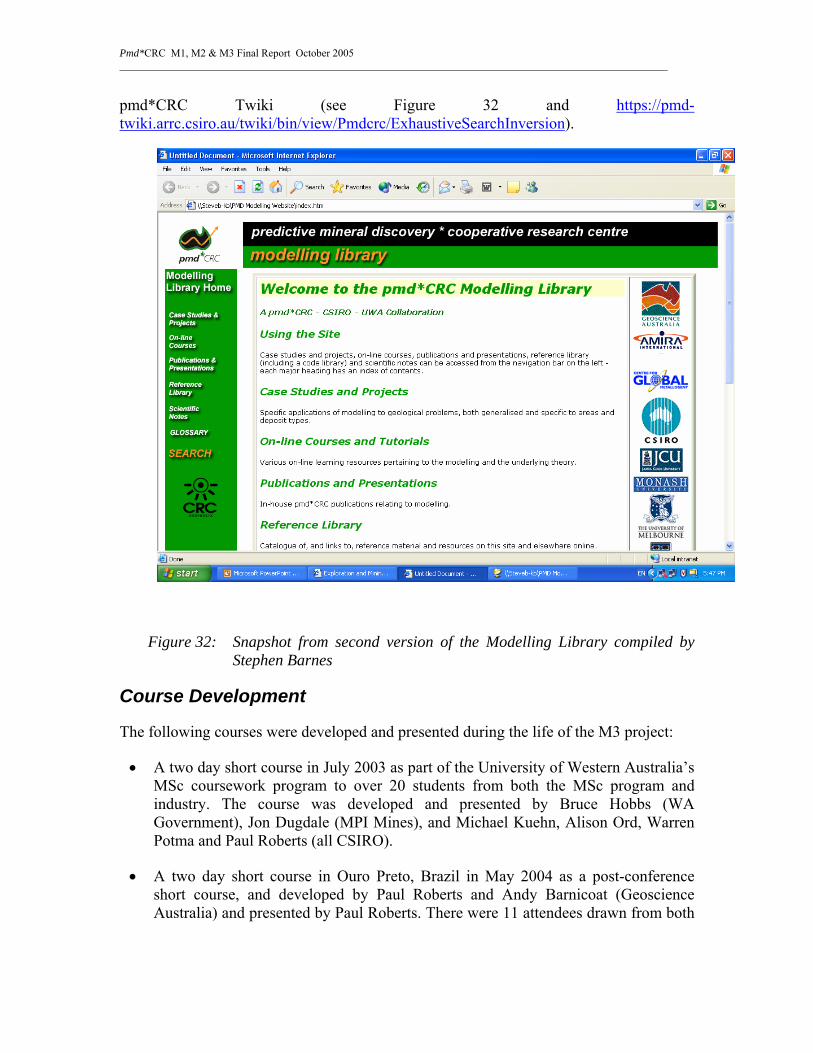
Pmd*CRC M1, M2 & M3 Final Report October 2005 _______________________________________________________________________________________________________
pmd*CRC Twiki (see Figure 32 and https://pmd-twiki.arrc.csiro.au/twiki/bin/view/Pmdcrc/ExhaustiveSearchInversion).
Figure 32: Snapshot from second version of the Modelling Library compiled by Stephen Barnes
Course Development
The following courses were developed and presented during the life of the M3 project:
• A two day short course in July 2003 as part of the University of Western Australia’s MSc coursework program to over 20 students from both the MSc program and industry. The course was developed and presented by Bruce Hobbs (WA Government), Jon Dugdale (MPI Mines), and Michael Kuehn, Alison Ord, Warren Potma and Paul Roberts (all CSIRO).
• A two day short course in Ouro Preto, Brazil in May 2004 as a post-conference short course, and developed by Paul Roberts and Andy Barnicoat (Geoscience Australia) and presented by Paul Roberts. There were 11 attendees drawn from both

Pmd*CRC M1, M2 & M3 Final Report October 2005 _______________________________________________________________________________________________________
industry and academic backgrounds. The course focus was the 5 Questions approach to mineral system analysis.
• A one day pre-conference workshop for the SEG Conference in Perth in September 2004, which was developed and presented by Paul Roberts, Alison Ord and Nick Oliver (from James Cook University). The course was attended by some 30 participants, both from the industry as well as international and local researchers. The course focused on three case histories - Wallaby, Ernest Henry and Stawell.
• In the last quarter of 2004, Klaus Gessner and Warick Brown (both UWA), Kevin Tuckwell (MTEC) and Reid Keays (Monash) commenced planning for a one-week Honours/MSc course on numerical modeling of ore deposition processes at both UWA and the VIEPS Universities in 2005. The first VIEPS course was cancelled owing to lack of potential attendees, however better advertised courses are confidently expected to succeed in future years.
• Paul Roberts and John McLellan (JCU) developed and presented course material for part of a 4 day module of the JCU Masters program for presentation in early April 2005. The module was addressed at both mechanical/fluid flow and chemical modeling (the latter developed as part of the fluids program by Nick Oliver and James Cleverley, both of JCU) with a section on risk analysis at the end, all built around the fictional “Egrulia” case history.
• Klaus Gessner, Paul Roberts, Michael Kuehn and Alison Ord developed and presented a second course as a component of the UWA Masters course program in July 2005.
• Klaus Gessner participated in redesigning an undergraduate course on Mineral Resources for geology and engineering students at University of Western Australia, parts of which he taught in March-April 2005.
M3 project external presentations
Name Date Title/Venue
Paul Roberts September 2002
“How Process Modelling Can Help with Targeting Strategies” - AIG Conference on Applied Structural Geology, Kalgoorlie.
Paul Roberts April 2003 “Computer Simulation of Earth Processes for Mineral Exploration: Concepts and Case Studies” – ProExplo, Lima, Peru.

Pmd*CRC M1, M2 & M3 Final Report October 2005 _______________________________________________________________________________________________________
Warren Potma, Peter Schaubs, Bruce Hobbs, Alison Ord
February 2004
Mohr-Coulomb theory and numerical modelling: unravelling the Wallaby Au ore system. 17th AGC, Hobart.
Paul Roberts May 2004 Computer Simulation of Earth Processes for Mineral Exploration - Concepts and Case Studies. SIMEXMIN Conference, Ouro Preto, Brazil
Warren Potma, Peter Schaubs and Thomas Poulet
June 2004 Application of template-based generic numerical modelling to exploration at all scales, pmd*CRC Barossa Conference.
Selwyn Symposium
27 October, 2004
Melbourne
Presentations/Publications Presentations:
International Workshop on “Mantle Convection and Lithosphere Dynamics” (Hruba Skala, 13-18. September 2003)
Regenauer-Lieb, K. Morra, G. and Funiciello, F. (2003) “The physics of subduction: statics, kinematics and dynamics” (Invited Lecture).
SGTSG Conference (Kalbarri, 20-25 September 2003) – oral presentations.
Hobbs, B.E. (2003) “Spherical, deformable, shell tectonics”.
Regenauer-Lieb, K. and Yuen, D.A. (2003) “Modelling Shear Zones in Geology”.
Ord, A., Sheldon, H., Walters, N. and Hobbs, B.E. (2003) “Fault (and shear zone) valve pumping revisited”.
Zhang, Y., Ord, A., Hobbs, B.E., Roberts, P.A., Lin, G., Wang, Y and McLellan, J.G. (2003) “Modelling of rock deformation behaviours in crust: brittle failure versus plastic flow”.
17th Australian Geological Convention (Hobart, 8-13 February 2004)

Pmd*CRC M1, M2 & M3 Final Report October 2005 _______________________________________________________________________________________________________
Alt-Epping, P., Zhao, C. and Hobbs, B.E. (2003) “Convective fluid flow in a vertical fault plane and its control in the distribution of ore minerals and associated alternation patterns”.
Ord, A. (2003) “Faulting, damage and fluid flow”.
Ord, A., Schaubs, P., and Alt-Epping, P. (2003) “The Athabasca and Witwatersrand Mineralising System”.
Potma, W., Schaubs, P., Hobbs, B.E. and Ord, A. (2003) “Mohr-Coulomb Theory and Numerical Modelling: Unravelling the Wallaby Au System”.
Sheldon, H.A. and Ord, A. (2003) “The role of convection in the formation of hydrothermal ore deposits”.
Zhang, Y., Lin, G., Wang, Y.J., Roberts, P.A. and Ord, A. (2003) “Application of thermal-deformation-fluid flow modelling to mineral exploration in the Shui-Kou-Shan mineralization district, Hunan Province, China”.
Hobbs, B.E., Ord, A. & Regenauer-Lieb, K., “Fluid reservoirs in the crust seismic activity and mechanical coupling between the upper and lower crust”
McLellan, J.G., L. Feltrin, N. H. S. Oliver (2003), “Fluid Flow Modelling in an overpressured basin: Testing the Genetic Model of the Giant Mesoproterozoic Zn-Pb-Ag Century Zinc Deposit.”
Ord, A. (2003), “Faulting, damage and fluid flow”
Ord, A., Schaubs, P., and Alt-Epping, P., “The Athabasca and Witwatersrand Mineralising System”
Regenauer-Lieb, K., Hobbs, B.E. & Ord, A.,”On the Thermodynamics of Listric Faults”
Sheldon, H.A. & Ord, A., “The role of convection in the formation of hydrothermal ore deposits”
Zhang, Y., Lin, G., Wang, Y.J., Roberts, P.A. & Ord, A., “Application of thermal-deformation-fluid flow modelling to mineral exploration in the Shu-Kou-Shan mineralization district, Hunan Province, China”
Second International Symposium on Slip and Flow Processes in and below the Seismogenic Region, Japan, 8-13 March 2004.
Klaus Regenauer-Lieb, Bruce Hobbs and Alison Ord, “On the Thermodynamics of Listric Faults”.
Bruce E Hobbs, Alison Ord, Klaus Regenauer-Lieb and Barry Drummond, “Fluid reservoirs in the crust and mechanical coupling between the upper and lower crust”
Pmd*CRC M1, M2 & M3 Final Report October 2005 _______________________________________________________________________________________________________
The pmd*CRC Barossa Valley meeting (June 2004)
Regenauer-Lieb, K., Ord, A., Hobbs, B.W., Zhang, Y., Sheldon, H. And Wijns, C. The Science of Modelling at All Scales (in 5 sections).
Second International Symposium on Slip and Flow Processes in and below the Seismogenic Region, Japan, 8-13 March 2004.
Hobbs, B.E., Ord, A. and Regenauer-Lieb, K. “Fluid reservoirs in the crust, seismic activity and mechanical coupling between the upper and lower crust”
Ord, A., Hobbs, B.E. and Regenauer-Lieb, K., “Seismicity, damage and fluid flow.”
Regenauer-Lieb, K., Hobbs, B.E. and Ord, A., “On the thermodynamics of listric faults”.
Goldschmidt conference, Copenhagen Denmark, 5-11 June 2004.
Hobbs, B.E., Walshe, J.L., Ord, A., Zhang, Y. and Barnicoat, A. “The Witwatersrand Mineralising System”
Regenauer-Lieb, K., Walshe, J.L., Hobbs, B.E. and Ord, A. “Are volatile mantle plumes important for the origin of giant ore bodies”
Walshe, J.L., Hobbs, B.E., Ord, A., Regenauer-Lieb, K., Barnicoat, A. and Hall, G. “Hydrogen flux from the Earth's Core, the formation of giant ore deposits through earth history”
Instabilities across Scales Conference, Cairns, 13-17 September 2004.
Hobbs, B.E., Ord, A., Muhlhaus, H-B. and Zhang, Y. Scale invariance of folding instabilities.
Ord, A., Hobbs, B.E., Regenauer-Lieb, K. and Zhang, Y. “ab initio emergent phenomena“
Regenauer-Lieb, K., Hobbs, B.E., Yuen, D.A., Ord, A., Zhang, Y. and Muhlhaus, H.B. “From Point Defects to Plate Tectonic Faults”.
2nd PFC conference, Kyoto Japan, 26-30 October 2004.
Hobbs, B.E., Regenauer-Lieb, K. And Ord, A. Ab initio emergent phenomena in PFC.
Ord, A., Zhang, Y., Zhao, C., Hobbs, B.E. and Regenauer-Lieb, K. Fracturing and brecciation in PFC.
Regenauer-Lieb, K., Ord, A. and Zhang, Y. Multiscaling brittle-ductile shear zones.

Pmd*CRC M1, M2 & M3 Final Report October 2005 _______________________________________________________________________________________________________
32nd International Geological Congress, Florence Italy, 20-28 August 2004.
Jensen, L.A., Paterson, S.R., Hobbs, B.E., Ord, A. and Zhang, Y. “Temperature as a first order control of elasto-viscous folding: implications for modelling and field studies”
SEG Meeting 2004, Perth, 27 September – 1 October 2004.
Sorjonen-Ward, P., Ord, A., Kontinen, P., Alt-Epping, P., Zhang, Y. and Kuronen, U. “Some new geological constraints and numerical simulations of the formation and deformation of the Outokumpu Cu-Co-Ni-Zn-Au deposits”
Gordon Conference on Rock Deformation in Massachusetts, USA (August 2004)
Sheldon, H. “Questioning the fault valve model: An investigation of fluid flow and mixing in dilatant faults”
(see https://pmd-twiki.arrc.csiro.au/twiki/pub/Pmdcrc/ProjectM2/Gordon_poster.ppt, and Twiki page Project M2 Flow Into Dilatant Fault With Compaction Manuscript for further details of this work).
The European Geosciences Union (EGU) meeting in Vienna, 2005
Sheldon, H., “Faults as pathways versus faults as seals: Contrasting behavior of high and low porosity rocks”
Heather Sheldon co-convened a session on fault zone architecture and permeability at this meeting.
Further details of work in this area can be found on the TWiki at:
https://pmd-twiki.arrc.csiro.au/twiki/bin/view/Pmdcrc/SLGFaultsinSandstones.
15th conference on Deformation Mechanisms, Rheology and Tectonics (DRT) in Zurich , 2005
At the DRT meeting Heather Sheldon talked about recent progress on numerical modelling of faults, focusing in particular on the implementation of Damage Mechanics in FLAC3D
(see Twiki page https://pmd-twiki.arrc.csiro.au/twiki/bin/view/Pmdcrc/ProjectM2DamageMechanics).
7th International Workshop on Bifurcation, Instabilities and Degradation in Geomechanics (IW BIDG 2005) in Chania, Crete.
Ord, A. …..

Pmd*CRC M1, M2 & M3 Final Report October 2005 _______________________________________________________________________________________________________
Hobbs, B.E. …..
The book of abstracts for this conference is attached to:
https://pmd-twiki.arrc.csiro.au/twiki/bin/view/Pmdcrc/ProjectM2.
SGA Beijing Conference, 2005
Zhang, Y., Ord, A. and Roberts, P., Numerical modelling of coupled deformation and fluid flow in mineralisation processes.
STOMP meeting in Townsville, 2005.
Sheldon, H., Barnicoat, A. and Ord, A. “Faulting in porous rocks: Insights from numerical models based on critical state soil mechanics”
Patton, R. “Non-linear viscoelastic models of rock folding and faulting”
Ord, A. “Localisation and emergent phenomena”
Publications:
Hobbs, B.E., Ord, A. and Regenauer-Lieb, K. “Fluid reservoirs in the crust and mechanical coupling between the upper and lower crust” Earth, Planets, Space, 56, 1151-1161, 2004.
Ord, A., Hobbs, B.E. and Regenauer-Lieb, K. “A smeared seismicity constitutive model. Earth, Planets, Space,” 56, 1121-1133, 2004.
Regenauer-Lieb, K., Hobbs, B.E. and Ord, A. “On the thermodynamics of listric faults. Earth, Planets, Space’, 56, 1111-1120, 2004.
Zhao, C., Lin, G., Hobbs, B. E., Ord, A., Wang, Y. and Muhlhaus, H. B., Effects of hot intrusions on pore-fluid flow and heat transfer in fluid-saturated rocks, Computer Methods in Applied Mechanics and Engineering, 192, 2007-2030 (2003).
Zhao, C., Hobbs, B. E., Ord, A., Lin, G. and Muhlhaus, H. B., An equivalent algorithm for simulating thermal effects of magma intrusion problems in porous rocks, Computer Methods in Applied Mechanics and Engineering, 192, 3397-3408 (2003).
In press:
Sheldon, H. A. and Ord, A. (2005), Evolution of porosity, permeability and fluid pressure in dilatant faults post-failure: Implications for fluid flow and mineralization. Geofluids V.. Page proofs can be found at:

Pmd*CRC M1, M2 & M3 Final Report October 2005 _______________________________________________________________________________________________________
https://pmd-twiki.arrc.csiro.au/twiki/pub/Pmdcrc/ProjectM2FlowIntoDilatantFaultWithCompactionManuscript/Sheldon_and_Ord_2005_proofs.pdf.
Zhang, Y., Sorjonen-Ward, P. and Ord, A. (2005): Modelling fluid transport associated with mineralizatio and deformation in the Outkumpu Cu-Z Co Deposit, Finland. Geofluid V, Conference Proceedings, Journal of Geochemical Exploration.
Zhang, Y., Sorjonen-Ward, P., Ord, A. and Southgate, P., Fluid Flow during Deformation Associated with Structural Closure of the Isa Superbasin after 1575 Ma in the Central and Northern Lawn Hill Platform, Northern Australia”. Economic Geology.
Gessner, K., Wijns, C and Moresi, L.(2005), Thermal-mechanical modeling of tectonic denudation in metamorphic core complexes. Tectonics.
In preparation:
Ord, A., Hobbs, B.E. and Regenauer-Lieb, K.R, Emergent Fracture Systems: Numerical Modelling with a Particle Flow Code.
Zhang, Y., Zhao, C. and Ord, A, Fracture development at an outcrop scale.
References Coleman, B. D., and W. Noll (1960), An approximation theorem for functionals with applications in continuum mechanics, Archive for Rational Mechanics and Analysis, 6, 355-370.
Hobbs, B. E. (1972), Deformation of non-Newtonian materials in simple shear, in Flow and fracture of rocks, edited, pp. 243-258, American Geophysical Union, Washington D.C.
Hobbs, B. E., et al. (1976), An Outline of Structural Geology, 571 pp., John Wiley & Sons, New York.
Joseph, D. D. (1989), Remarks on inertial radii, persistent normal stresses, secondary motions, and non-elasitic extensional viscosities, Journal of Non-Newtonian Fluid Mechanics, 32, 107-117.
Reches, Z. 1988. Evolution of fault patterns in clay experiments. Tectonophysics 145, 141-156.
Rispoli, R. 1981. Stress fields about strike-slip faults inferred from stylolites and tension gashes. Tectonophysics 75, T29-T36.
Rivlin, R. S., and J. L. Ericksen (1955), Stress-deformation relations for isotropic materials, Journal of Rational Mechanics and Analysis, 4, 323-425.

Pmd*CRC M1, M2 & M3 Final Report October 2005 _______________________________________________________________________________________________________
Rundle, J. B., and S. L. Passman (1982), Constitutive laws, tensorial invariance and chocolate cake, Geophysical Surveys, 5, 3-36.
Zhang, Y., Hobbs, B.E., Ord, A., Barnicoat, A., Zhao, C., Walshe, J.L. & Ge Lin 2003. The influence of faulting on host-rock permeability, fluid flow and mineral precipitation: a conceptual 2D numerical model. Journal of Geochemical Exploration 78-79, 279-284.