prediction of gas holdup in various types of airlift reactors
TRANSCRIPT

1781
Korean J. Chem. Eng., 38(9), 1781-1790 (2021)DOI: 10.1007/s11814-021-0822-4
INVITED REVIEW PAPER
pISSN: 0256-1115eISSN: 1975-7220
INVITED REVIEW PAPER
†To whom correspondence should be addressed.E-mail: [email protected] by The Korean Institute of Chemical Engineers.
Prediction of gas holdup in various types of airlift reactors
Keun Ho Choi†
Department of Chemical and Biological Engineering, Hanbat National University,125, Dongseodaero, Yoseong-gu, Daejeon 305719, Korea
(Received 15 February 2021 • Revised 5 April 2021 • Accepted 23 April 2021)
AbstractUseful correlations were derived for the prediction of available gas holdup data in air-water systems, usingthe operational and geometric parameters of airlift reactors only. To successfully consider the geometric differencebetween various types of airlift reactors, the characteristic distance (Dch) and the gas separation area (As) were definedas geometric parameters, respectively. The riser gas holdup (r) in various types of airlift reactors was satisfactorily cor-related with the operational and geometric parameters, such as the riser superficial gas velocity (UGr), a parameter con-taining the ratio of the top clearance to downcomer length (1+Ct/Ld), the characteristic distance to downcomer lengthratio (Dch/Ld), the downcomer to riser cross-sectional area ratio (Ad/Ar), the ratio of the gas separation area to risercross-sectional area (As/Ar), and the bottom to downcomer cross-sectional area ratio (Ab/Ad). The downcomer gasholdup in various types of airlift reactors was well correlated by a nonlinear equation involving r, Dch/Ld, Ad/Ar, Ab/Ad,(1+Ct/Ld), and As/Ar.Keywords: Prediction, Gas Holdup, Airlift Reactor, Characteristic Distance, Gas Separation Area
INTRODUCTION
Airlift reactors can be clearly classified into two large groups:external-loops and internal-loops [1-3]. External-loop airlift reac-tors have two separate and vertical pipes that are joined by the topand bottom connections. Sometimes the connections are horizon-tal pipes. Gas-liquid separation takes place in the top region of theairlift reactors including the top connection pipe. A rectangulartank is frequently used as the top connection in order to increaseits mixing performance and gas-liquid separation efficiency. Accord-ingly, the rectangular tank is especially called a gas-liquid separa-tor. One of these vertical pipes is the riser, which has an upwardflow of fluid. The other pipe is the downcomer, which has a down-ward flow of fluid. Internal-loop airlift reactors are characterizedby having a vessel that is divided by a vertical baffle or a draft-tube.The cross-section of the vessel is usually circular, sometimes rect-angular [4]. The top and the bottom of the vessel take roles of thetop and the bottom connection for external-loop airlift reactors,respectively.
Many researchers have investigated a large number of modifiedairlift reactors: the riser with various internals (baffles [5,6], perfo-rated plates [7-10], disks [11], static mixers [12-14], impellers [15,16], packing materials [17]), multiple draft tubes [18,19], the enlargedtop [20-24], inclined connection pipes [14,25-28], the downcomerwithout an extension tube [29-33], multi-stages [34,35], the top withfunnel internals [36], and net draft tubes [37]. Therefore, there aremany types of airlift reactors. Different morphologies of airlift reac-tors result in very different trends of performance factors such asgas holdup, mixing time, circulation liquid velocity, and oxygen trans-
fer coefficient.All researchers observed that the riser and downcomer gas hold-
ups increase with the riser superficial gas velocity (UGr). Bello et al.[38] expressed the gas holdup as a function of specific power inputinstead of the gas velocity. The influence of the bottom and topclearances on the gas holdup was studied by Koide et al. [39], Mer-chuk et al. [22], Choi [40], and Gouveia et al. [41]. A large numberof published works on airlift reactors have focused on the effect ofthe downcomer to riser cross-sectional area ratio (Ad/Ar) [4,42-50]. There are some correlations on the gas holdups as a functionof the superficial liquid velocity (ULr) [44,51-55]. The length of theconnection pipe or the distance between the riser and downcomeraxes has also a strong effect on the gas holdup [47,48,56]. Zhao etal. [8], Rujiruttanakul and Pavasant [28], Kojić et al. [57], and Luoet al. [58] reported that the sparger structure had a significant effecton the gas holdup and downcomer liquid velocity. Some research-ers studied the effect of liquid properties such as viscosity anddensity on the gas holdup [39,42,45,46,53,55, 57,59,60].
Up to now, many correlations for gas holdup in airlift reactorshave been reported in the literature. However, most of the correla-tions are only useful for a particular type of airlift reactor fromwhich they were derived. The gas holdup data obtained in the othertype of airlift reactors differed greatly from the correlations. There-fore, the previous correlations for gas holdup are extremely limitedin use.
If we obtain a correlation equation that can well predict a largeamount of the gas holdup obtained in various types of airlift reac-tors, we can use it more usefully than previous correlations for reac-tor design. Therefore, in this work, new geometric parameters suchas the characteristic distance (Dch) and the gas separation area (As)were defined and used to reflect the effect of reactors’ geometricaldifference on the gas holdup. We attempted to correlate as manygas holdup data obtained in four basic types of airlift reactors and
1782 K. H. Choi
September, 2021
air-water systems as possible with the operational and geometricparameters only. The operational parameters were the riser super-ficial gas velocity (UGr) and a parameter containing the ratio of topclearance to downcomer length (1+Ct/Ld). The geometric parame-ters were ratios between the free areas of conduits for circulationliquid [i.e., the downcomer to riser cross-sectional area ratio (Ad/Ar), the bottom to downcomer cross-sectional area ratio (Ab/Ad)]as well as the ratio of the characteristic distance to the downcomerlength (Dch/Ld) and the ratio of the gas separation area to riser area(As/Ar).
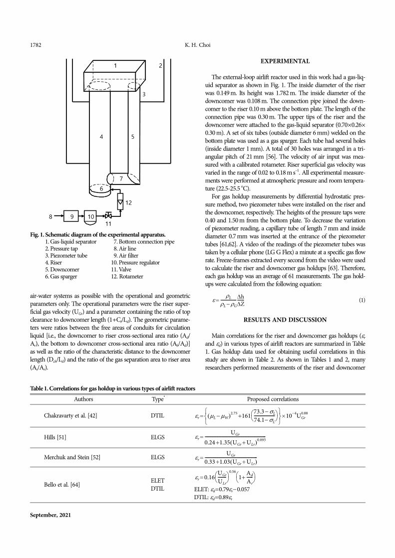
Fig. 1. Schematic diagram of the experimental apparatus.1. Gas-liquid separator 07. Bottom connection pipe2. Pressure tap 08. Air line3. Piezometer tube 09. Air filter4. Riser 10. Pressure regulator5. Downcomer 11. Valve6. Gas sparger 12. Rotameter
Table 1. Correlations for gas holdup in various types of airlift reactorsAuthors Type* Proposed correlations
Chakravarty et al. [42] DTIL
Hills [51] ELGS
Merchuk and Stein [52] ELGS
Bello et al. [64] ELETDTIL ELET: d=0.79r0.057
DTIL: d=0.89r
r L W 2.75 161
73.3 L
74.1 L--------------------
104UGr0.88
r UGr
0.24 1.35 UGr ULr 0.093----------------------------------------------------------
r UGr
0.33 1.03 UGr ULr --------------------------------------------------
r 0.16UGr
ULr--------
0.561
Ad
Ar------
EXPERIMENTAL
The external-loop airlift reactor used in this work had a gas-liq-uid separator as shown in Fig. 1. The inside diameter of the riserwas 0.149 m. Its height was 1.782 m. The inside diameter of thedowncomer was 0.108 m. The connection pipe joined the down-comer to the riser 0.10 m above the bottom plate. The length of theconnection pipe was 0.30 m. The upper tips of the riser and thedowncomer were attached to the gas-liquid separator (0.70×0.26×0.30 m). A set of six tubes (outside diameter 6 mm) welded on thebottom plate was used as a gas sparger. Each tube had several holes(inside diameter 1 mm). A total of 30 holes was arranged in a tri-angular pitch of 21 mm [56]. The velocity of air input was mea-sured with a calibrated rotameter. Riser superficial gas velocity wasvaried in the range of 0.02 to 0.18 m s1. All experimental measure-ments were performed at atmospheric pressure and room tempera-ture (22.5-25.5 oC).
For gas holdup measurements by differential hydrostatic pres-sure method, two piezometer tubes were installed on the riser andthe downcomer, respectively. The heights of the pressure taps were0.40 and 1.50 m from the bottom plate. To decrease the variationof piezometer reading, a capillary tube of length 7 mm and insidediameter 0.7 mm was inserted at the entrance of the piezometertubes [61,62]. A video of the readings of the piezometer tubes wastaken by a cellular phone (LG G Flex) a minute at a specific gas flowrate. Freeze-frames extracted every second from the video were usedto calculate the riser and downcomer gas holdups [63]. Therefore,each gas holdup was an average of 61 measurements. The gas hold-ups were calculated from the following equation:
(1)
RESULTS AND DISCUSSION
Main correlations for the riser and downcomer gas holdups (r
and d) in various types of airlift reactors are summarized in Table1. Gas holdup data used for obtaining useful correlations in thisstudy are shown in Table 2. As shown in Tables 1 and 2, manyresearchers performed measurements of the riser and downcomer
L
L G----------------
hZ-------
Prediction of gas holdup in various types of airlift reactors 1783
Korean J. Chem. Eng.(Vol. 38, No. 9)
Table 1. ContinuedAuthors Type* Proposed correlations
Bello et al. [38] ELET
Chisti et al. [43]RIL
bubble flow:
coalesced bubble flow:
ELET
Miyahara et al. [53] DTIL
Popović and Robinson [46] ELET
Choi et al. [56] ELET
Philip et al. [54] DTIL where
C2=0.24-0.33 for Newtonian flowC2=0.35 for Non-Newtonian flow
Choi and Lee [47] ELET
Kemblowski et al. [55] ELGS
Merchuk et al. [22] DTIL
Bentifraouine et al. [65] ELETELGS r=2UGr
0.88(10.97ULr0.49)
Couvert et al. [66] SRIL r=0.137UGr0.92
Lu et al. [4] DTIL
Choi [48] ELCD
r 3.4 103 1 Ad
Ar------
1 PG
VD------
2/3
r 1.488 0.496Cs UGr
1 Ad/Ar---------------------
0.892±0.075
r 0.371 0.089Cs UGr
1 Ad/Ar---------------------
0.430±0.015
r 0.65 1 Ad
Ar------
0.258UGr
0.603±0.078Cs
r 0.4 Fr
'
1 0.4 Fr' 1 ULr/UGr
-----------------------------------------------------
d 4.51 106M0.115 Ar
Ad------
4.2r
4.2 for d 0.0133Ar
Ad------
1.32
d 0.55M0.22 Ar
Ad------
0.6r
0.31M0.073
for d 0.0133Ar
Ad------
1.32
r 0.465UGr0.650 1
Ad
Ar------
1.06eff0.103
r 0.43UGr0.65 Lc
Lco------
0.15
d 0.09UGr1.01 Lc
Lco------
0.92
r = UGr
C1 UGr ULr C2 gDc
------------------------------------------------------- C1 3n 1n 1-------------
r 0.288UGr0.504 Ad
Ar------
0.098 Lc
Lh-----
0.094
d 0.049UGr1.138 Ad
Ar------
0.885 Lc
Lh-----
0.462
r 0.203
UGr ULr
gDr---------------------
0.31
g L G k4
L3L
2----------------------------
8ULr
Dr----------
4 n1 3n 14n
-------------
4n0.012
UGrAr
ULrAd--------------
0.57---------------------------------------------------------------------------------------------------------------------
r 1.5UGc
gDc
------------
0.87 Ds
4Dc--------
0.04 Cb
Dc-----
0.19 Ct
Dd------
0.2
d 4.76UGc
gDc
------------
1.3 Ds
4Dc--------
3.8 Cb
Dc-----
0.65 L2Dc
3Ct
2
-----------------
0.09
r 0.035UGr0.647 Ad
Ar------
0.085
r 0.431UGr0.580 Ad
Ar------
0.040 Lc
Lh-----
0.042

1784 K. H. Choi
September, 2021
gas holdups in four basic types of airlift reactors, such as draft-tubeinternal-loop (DTIL), split rectangular internal-loop (SRIL), exter-nal-loop with an extension tube (ELET), and external-loop with agas-liquid separator (ELGS). Previous investigations show that thegas holdup depends on the operational and geometric parametersof the reactors. The operational parameters are superficial gas veloc-ity, superficial liquid velocity, top clearance (or liquid volume), andproperties of liquids. The main construction parameters of airliftreactors are the downcomer to riser cross-sectional area ratio (Ad/Ar), the bottom clearance, the connection pipe to downcomerlength ratio (Dc/Ld), design of the gas sparger, and details of thegas-liquid separator.
The main parameters that influence the riser gas holdup in var-ious types of airlift reactors must be taken into account in order toachieve a meaningful correlation of the results. However, the risersuperficial liquid velocity, design of the gas sparger, and propertiesof the liquid (for instance, viscosity, surface tension, and ionic con-centration) were not considered because of two reasons: first, theireffect on gas holdup was not experimented in this study; second,there is still not enough research literature on their effect on gasholdup in airlift reactors.
In this work, in order to successfully correlate as many gas holdupdata as possible, the characteristic distance (Dch) and the gas sepa-ration area (As) for each type of airlift reactors were defined andwere used as geometric parameters. The characteristic distance wasdefined as follows:
for DTIL (2)
for SRIL (3)
for ELET and ELGS (4)
If air bubbles released from the riser do not separate from thegas-liquid mixture in the top region including the top connectionpipe, they flow into the downcomer by liquid circulation. Most largebubbles are separated just after the time when the circulation liq-uid changes its direction to the downcomer. After that, when thecirculation liquid flows through the horizontal conduits such as thetop connection pipe and the gas-liquid separator, small bubblescontinuously go up the liquid surface due to buoyancy force andeffectively escape from the liquid because the liquid height in theconduits is low. The longer the horizontal distance which bubblestravel from the riser to the downcomer, the fewer bubbles are en-trained into the downcomer. In general, the horizontal distance forinternal-loop airlift reactors is smaller than that for external-loopairlift reactors. In addition, it is certain that the longer the resi-dence time of the circulation liquid in the top region, the smallerthe downcomer gas holdup is. Considering the phenomenon, thegas separation area (As) was defined as the largest cross-sectionalarea of the top region in Fig. 2. For external-loop airlift reactors
Dch Dd Dc
4-----------------
Dch Wr Wd
2--------------------
Dch Dr
2-----
Dd
2------ Lc
Table 1. ContinuedAuthors Type* Proposed correlations
Choi [49] ELGS
Gouveia et al. [41] DTIL
Al-Masry [67] ELGS
Yazdian et al. [50] ELCDr=0.47d
Rujiruttanakul and Pavasant [28] ELET r=0.49UGr0.67Lc
0.15Lh0.22
d=0.29UGrLc0.45Lh
0.39
Kojić et al. [57] ELGS
*DTIL, draft-tube internal-loop; ELCD, external-loop with a closed downcomer; ELET, external-loop with an extension tube; ELGS, external-loop with a gas-liquid separator; RIL, rectangular internal-loop; SRIL, split rectangular internal-loop.
r 0.2447UGr0.5616 Ad
Ar------
0.2779Ct
0.0130
r 11.97UGr
gDr
------------
1.31 Cb
Dr-----
0.42 Ct
Dr----- 1
2.44
d 13.52UGr
gDr
------------
1.46 Cb
Dr-----
0.72 Ct
Dr----- 1
5.21
r 3.84 0.73UGr 1 1.33 1
1/1.33
× 0.0067TVR 1.095Ad Ar
Ar----------------
0.084Lexp
d 2.69 0.47UGr 1 1.29 1
1/1.29
× 0.011TVR 0.69Ad Ar
Ar----------------
0.075Lexp
r 13.19UGr1.43 1
Ar
Ad------
0.621 S 0.58 g
N2
-------
0.52
r 2.35UGr0.66
0.47
0.045 Ad
Ar------
0.61

Prediction of gas holdup in various types of airlift reactors 1785
Korean J. Chem. Eng.(Vol. 38, No. 9)
Table 2. Used gas holdup data for obtaining the correlationsNo. Authors Type Conditions Used data
01 Chakravarty et al. [42] DTIL Dc=0.1 m, Dd=0.059 m, Ld=0.4, Cb=0.026 m, Ct=0.06 m, VL=3.8×10² m3, perforated plate sparger (=1.5 mm) r, d
02 Jones [68] DTIL Dc=0.25 m, Dd=0.044-0.146 m, Ld=1.22 m, Cb=0.1 m, Ct=0.01 m,tube sparger (=2.4 mm) r
03 Choi et al. [7] DTIL Dc=0.238 m, Dd=0.146 m, Ld=0.992 m, td=0.006 m, Hd=1.55 m,Cb=0.05 m, tube sparger (=1 mm) r, d
04 Miyahara et al. [53] DTIL Dc=0.148 m, Dd=0.07 m, Ld=1.0 m, td=0.005 m, Cb=0.08 m, Ct=0.06 m, perforated plate sparger (=1 mm) r
05 Wachi et al. [69] DTIL Dc=0.22 m, Dd=0.12 m, Ld=1.95 m, UGr=0.02-0.07 m, td=0.005 m,Cb=0.05 m, VL=8.5×10² m3, perforated plate sparger (=0.5 mm) r, d
06 Petrović et al. [70] DTIL Dc=0.20 m, Dd=0.08-0.15 m, Ld=2 m, td=0.006 m, Cb=0.040 m, per-forated plate sparger (=1 mm) r, d
07 Merchuk et al. [22]DTIL Dc=0.318 m, Dd=0.216 m, Ld=3.27 m, td=0.041 m, Cb=0.01-0.08 m,
Ct=0.04 m, VL=3.00×101 m3, ring sparger (=1 mm) r, d
DTIL Dc=0.158 m, Dd=0.110 m, Ld=1.395 m, Ds=0.213 m, Cb=0.012 m,Ct=0.308 m, VL=3.0×10² m3, ring sparger (=1 mm) d
08 Lu et al. [71] DTIL Dc=0.18 m, Dd=0.12 m, Ld=1.10 m, tb=0.005 m, Cb=0.10 m, Ct=0.20 m, UGr=0.015-0.147 m s1, ring sparger r, d
09 Blažey et al. [24] DTILDc=0.147 m, Dd=0.106 m, Ld=1.71 m, td=0.006 m, HL=1.818 m,Ds=0.294 m, Cb=0.046 m, Ct=0.062 m, VL=3.2×10² m3, perforatedplate sparger
r, d
10 Blažey et al. [72] DTIL Dc=0.294 m, Dd=0.200 m, Ld=2.7 m, HL=2.936 m, Cb=0.061 m, Ct=0.175 m, VL=2.00×101 m3, perforated plate sparger r, d
11 Siegel et al. [61] SRIL Wr=0.07 m, Wd=0.09 m, Wc=0.25 m, Ld=4.0 m, Cb=Ct=0.10 m, Ls×Ws×Hs=0.32×0.25×0.64 m, =0.5-2.5 mm, straight baffle r
12 Couvert et al. [66] SRIL Wr=Wd=0.25 m, Wc=0.5 m, Ld=2.35 m, Cb=0.15 m, Ct=0.1 m, UGr=0.011-0.045 m s1, tubular plastic membranes r, d
13 Popović and Robinson [73] ELET Dr=0.15 m, Dd=0.05 m, Ld=1.78 m, Lc=0.432 m, Ct=0 m**, perfo-rated plate sparger (=1 mm) r
14 Choi and Lee [47] ELET Dr=0.149 m, Dd=0.049-0.108 m, Ld=0.992 m, Lc=0.10-0.50 m, Hd=1.77 m, UGr=0.02-0.18 m s1, tube sparger (=1 mm) r, d
15 Al-Masry and Dukkan [74] ELET Dr=Dd=0.225 m, Ld=7.5 m, Lc=1.2 m, VL=0.7 m3, plate sparger r, d
16 Bentifraouine et al. [75] ELET Dr=0.194 m, Dd=0.92 m, Ld=0.908 m, H=1.40 m, Dch=0.50 m, Ct=0 m**, ring sparger (=0.8 mm) r
17 Rujiruttanakul andPavasant [28] ELET Dr=0.104 m, Dd=0.054 m, Ld=1.346 m, Lc=0.2 m, Ct=0.03 m, HL=
1.56 m, porous plate sparger r, d
18 Kemblowski et al. [55] ELGS Dr=Dd=0.100 m, Ld=1.800 m, Lc=0.40 m**, Hd=1.77 m, UGr=0.015-0.09 m s1, Ls×Ws×Hs=1.00×0.30×0.30 m, porous plate sparger r
19 Bentifraouine et al. [65] ELGS Dr=0.194 m, Dd=0.093 m, H=1.60 m, Dch=0.50 m, tube sparger (=0.6 mm) r
20 Choi [40] ELGSDr=0.149 m, Dd=0.049-0.108 m, Ld=1.578 m, Lc=0.3 m, Ct=0-0.20m, UGr=0.20-0.18 m s1, Ls×Ws×Hs=0.70×0.26×0.30 m, tube sparger(=1 mm)
r
21 This work ELGSDr=0.149 m, Dd=0.108 m, Ld=1.578 m, Lc=0.3 m, Ct=0 m, UGr=0.02-0.18 m s1, Ls×Ws×Hs=0.70×0.26×0.30 m, tube sparger (=1 mm)
r, d
**Assumed value

1786 K. H. Choi
September, 2021
with the extension tube, it was the sum of the cross-sectional areasof the riser, the downcomer, and the top connection pipe.
To predict liquid circulation velocity, Chisti et al. [76] definedthe bottom clearance area (Ab) between the riser and the down-comer (the hatched area in Fig. 2). In this work, considering theeffect of the bottom clearance on the gas holdup, the bottom clear-ance area was used as a geometric parameter. Finally, the selectedparameters for the prediction of gas holdup in various types of air-lift reactors were the riser superficial gas velocity (UGr), a parame-ter containing the ratio of the top clearance to downcomer length(1+Ct/Ld), the characteristic distance to downcomer length ratio(Dch/Ld), the downcomer to riser cross-sectional area ratio (Ad/Ar),the ratio of the gas separation area to riser cross-sectional area (As/Ar), and the bottom to downcomer cross-sectional area ratio (Ab/Ad).
Available riser gas holdup data for the internal-loop and exter-nal-loop airlift reactors in the literature are presented in Figs. 3 and
4, respectively. The dotted line in Fig. 4 represents my data mea-sured in this work, while the solid lines in Figs. 3 and 4 represent aselected part of the data to show the trends of the riser gas holdupas a function of the riser superficial gas velocity. The riser gas holdupincreased with increasing superficial gas velocity. At low gas veloci-ties, the riser gas holdup increased sharply, while at high gas veloci-ties it became constant. Most of the reported data on gas holdupin the riser differentiated between the geometrical differences ofthe reactors. Regardless of the internal-loop and external-loop airliftreactors, at a given value of the superficial gas velocity, the riser gasholdup could differ from reactor to reactor up to about four times.
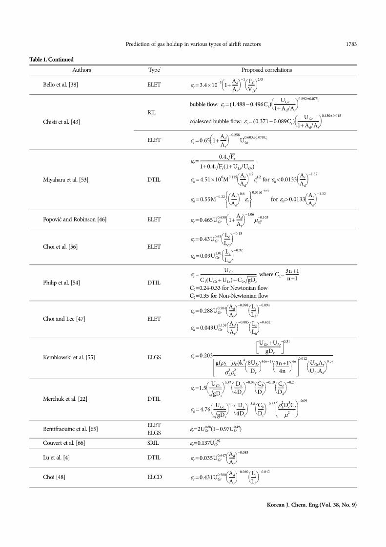
A correlation involving UGr and dimensionless form of parame-ters, such as Dch/Ld, Ad/Ar, Ab/Ad, As/Ar, (1+Ct/Ld), was used to de-scribe the variations of the riser gas holdup in the reactors. Theresults are plotted in Fig. 5. The riser gas holdup in the literature andmy data in air-water systems are well represented by Eq. (5), witha respective correlation coefficient of 0.91. Eq. (5) fits 288 data with
Fig. 2. Definitions of cross-sectional areas and dimensions: (a) Draft-tube internal-loop; (b) split rectangular internal-loop; (c) external-loopwith an extended tube; (d) external-loop with a gas-liquid separator.
Fig. 3. Riser gas holdup in internal-loop airlift reactors. See Table 2for legend.
Fig. 4. Riser gas holdup in external-loop airlift reactors. See Table 2for legend.
Prediction of gas holdup in various types of airlift reactors 1787
Korean J. Chem. Eng.(Vol. 38, No. 9)
the mean absolute percentage error of 16.5%.
(5)
The ranges of the parameters are 0.02Dch/Ld0.638, 0.108Ad/Ar30.99, 0.170Ab/Ad4.858, 1(1+Ct/Ld)1.384, 2As/Ar38.217,and 0.005 m s1
UGr0.37 m s1. As shown in Table 1, the data ofmost authors show that the range of the exponent for UGr is between0.415 [43] and 1.43 [50]. The exponent for UGr in Eq. (5) is slightlylower than 0.56 obtained by Bello et al. [64]. Choi [49] reportedthat the exponent for UGr was 0.5616.
A wide range of experimental conditions and various reactorconfigurations were considered in this work. As seen in Fig. 5, Eq.(5) is a useful means for predicting the riser gas holdup. The datain Fig. 5 represent 42 different airlift reactors covering approxi-mately 32-fold variation in Dch/Ld, about 287-fold variation in Ad/Ar, around 29-fold variation in Ab/Ad, approximately 1.4-fold vari-ation in (1+Ct/Ld) and around 19-fold variation in As/Ar. Thesebroad ranges demonstrate the applicability of Eq. (5) for airlift reac-tor design. Many conditions that show a larger deviation over ±30%than the calculated value by Eq. (5) are low gas velocity (0.07 ms1<UGr). Of those, the measured gas holdup of Blazey et al. [24] onaverage is 53% lower than predicted by Eq. (5). This difference canbe attributed to the high liquid velocity, caused by the enlarged topin their case. The data of Kemblowski et al. [55] also show rela-tively a large deviation. It may be due to the assumed value of Lc.
As previously pointed out, the top region in external-loop air-lift reactors can be an effective gas-liquid separator that ensuresthe disengagement of most air bubbles from the liquid before theyenter the downcomer. Therefore, the literature on the downcomergas holdup is relatively scant. The available downcomer gas holdupfor various types of airlift reactors in the literature, together with
my results, are shown in Fig. 6. The solid lines represent a selectedpart of the data for the internal-loop airlift reactors, whereas thedotted lines represent a selected part of the data for the external-loop airlift reactors. In general, at a specific gas velocity, the down-comer gas holdup for the external-loop airlift reactors is smallerthan that of the internal-loop airlift reactors because of increasingcirculation liquid velocity. Many researchers reported that the down-comer gas holdup was increased with increasing circulation liquidvelocity. In addition, at the same value of the superficial gas veloc-ity, the downcomer gas holdup could very much differ from reac-tor to reactor because of the difference between the gas-liquidseparation efficiency of the top regions. The top region of the air-lift reactor can be designed for complete gas-liquid separation [77].
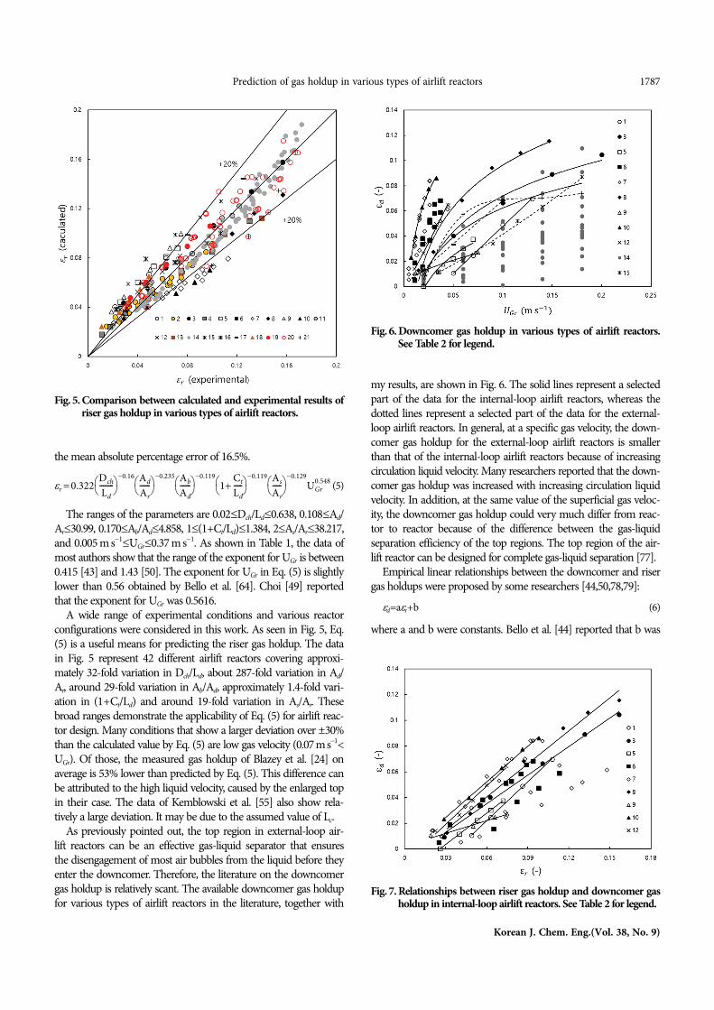
Empirical linear relationships between the downcomer and risergas holdups were proposed by some researchers [44,50,78,79]:
d=ar+b (6)
where a and b were constants. Bello et al. [44] reported that b was
r 0.322Dch
Ld--------
0.16 Ad
Ar------
0.235 Ab
Ad------
0.1191
Ct
Ld-----
0.119 As
Ar-----
0.129UGr
0.548
Fig. 5. Comparison between calculated and experimental results ofriser gas holdup in various types of airlift reactors.
Fig. 6. Downcomer gas holdup in various types of airlift reactors.See Table 2 for legend.
Fig. 7. Relationships between riser gas holdup and downcomer gasholdup in internal-loop airlift reactors. See Table 2 for legend.

1788 K. H. Choi
September, 2021
equal to 0 for the draft-tube airlift reactors. However, as shown inFig. 7, it is certain that the dependency of the constants in Eq. (6)on geometric parameters is very complex even in the case of inter-nal-loop airlift reactors. Furthermore, for external-loop airlift reac-tors, the relationship between the riser and downcomer gas holdupsis nonlinear as Fig. 8 shows. Miyahara et al. [53] also obtained anonlinear relationship for the draft-tube airlift reactors as shownin Table 1. My own data in the external-loop airlift reactor withthe effective gas-liquid separator show a very different trend dueto the surface aeration.
Taking all these aspects into account, in this paper, an equationwas derived for the prediction of the downcomer gas holdup inairlift reactors in air-water systems, using available data from theliterature and my experimental data. The downcomer gas holdupdata in various types of airlift reactors are well represented by Eq.(7), with a respective correlation coefficient of 0.83. Eq. (7) predicts137 data with a mean absolute percentage error of 21.1%.
(7)
The ranges of the parameters are d>0.01, 0.037Dch/Ld0.638, 0.108Ad/Ar4.928, 0.170As/Ar4.858, 1(1+Ct/Ld)1.367, and 1.778As/Ar10.443. It may be concluded that this correlation provides areasonable estimation of the downcomer gas holdup in varioustypes of airlift reactors.
The measured and calculated values of the downcomer gasholdup are given in Fig. 9. As already mentioned, the external-loop airlift reactor with the gas-liquid separator well-designed keepsthe downcomer almost free of gas bubbles at lower gas velocity[77]. At higher gas velocity, either air pockets at the entrance of thedowncomer or a vortex above it in the gas-liquid separator takeplace because of high circulation liquid velocity. The air pocketsand the vortex accompany surface aeration [63]. The surface aera-tion hardly ever happens in other types of airlift reactors. However,despite the surface aeration, the downcomer gas holdup for theexternal-loop airlift reactor with the gas-liquid separator is muchlower than that for other types of airlift reactors due to the effec-
tive gas-liquid separation. Therefore, the measured downcomer gasholdup in this study on average is approximately 53% lower thanpredicted by Eq. (7). It means that Eq. (7) maybe is not enough todescribe the effect of the surface aeration on the downcomer gasholdup. We need further research to reflect well the surface aera-tion in a generally applicable equation for airlift reactor design.
We can use the correlations presented in this study for airliftreactor design. Eq. (5) and Eq. (7) allow us to gain various combi-nations of the operational and geometric parameters to obtain spe-cific gas holdups. In particular, it will help determine one of theoperational and geometric parameters, given all other parameters.The type of the reactor can be naturally determined from valuesof Dch/Ld and As/Ar.
CONCLUSION
Most researchers have correlated their own data of gas holdupwith the operational and geometric parameters for a particular typeof airlift reactors. There was little attempt to obtain an equationthat could correlate available gas holdup data, especially measuredin different types of airlift reactors.
The geometric characteristics of airlift reactors exert an import-ant influence on the riser and downcomer gas holdup. To success-fully consider the geometric difference between various types ofairlift reactors, the characteristic distance (Dch) and the gas separa-tion area (As) were defined and used in this work. The ratio of thecharacteristic distance to the downcomer length (Dch/Ld) was foundto be an effective parameter that could correlate many gas holdupdata obtained in various types of airlift reactors, as was the ratio ofthe gas separation area to riser area (As/Ar).
A meaningful correlation involving UGr and dimensionless formof geometric parameters, such as (1+Ct/Ld), Dch/Ld, Ad/Ar, Ab/Ad,
d 1.85r1.14 Ad
Ar------
0.2841
Ct
Ld-----
1.92 As
Ar-----
0.652 0.216
Lch
Ld------
4.10 Ab
Ad------
6.25
Fig. 8. Relationships between riser gas holdup and downcomer gasholdup in external-loop airlift reactors. See Table 2 for legend.
Fig. 9. Parity plot of downcomer gas holdup correlation, Eq. (7), forvarious types of airlift reactors. See Table 2 for legend.

Prediction of gas holdup in various types of airlift reactors 1789
Korean J. Chem. Eng.(Vol. 38, No. 9)
As/Ar, was obtained for predicting the riser gas holdup in varioustypes of airlift reactors. The downcomer gas holdup in various typesof airlift reactors was well correlated by a nonlinear equation involv-ing r, (1+Ct/Ld), Dch/Ld, Ad/Ar, Ab/Ad, and As/Ar. Eq. (5) and Eq.(7) obtained in this study can be used in determining the type anddimensions of an airlift reactor.
It is a big step forward in generalization that we were able torepresent a large amount of data from many researchers with onecorrelation at this time. Obtaining a correlation equation that cansuccessfully represent much data on gas holdup obtained in vari-ous types of airlift reactors and air-water systems is the basis forderiving a more generalized correlation equation, reflecting the risersuperficial liquid velocity, design of the gas sparger, and the prop-erties of the liquid. To obtain a generalization that includes all otherparameters that were not considered in this study, it will requirethe efforts of many researchers in the future.
NOMENCLATURE
A : cross-sectional area [m2]a : constantb : constant
C1 : constant=
C2 : constantCb : bottom clearance [m]Cs : dry weight solids per volume of suspension [%]Ct : top clearance [m]D : diameter [m]Dch : characteristic distance [m]Fr' : Froude number=U2
Gr/(g)g : gravitational acceleration [m s2]h : piezometer reading [m]H : height [m]Hd : aerated liquid height [m]HL : unaerated liquid height [m]k : consistency index in a power-law model [Pa sn]L : length [m]Lc : length of connection pipe [m]Lh : distance between connection pipe axes [m]M : Morton number=gL
4/(L3)
n : flow index in a power-law modelPG/VL : power input per volume of degassed liquid [kw m3]S : separator to downcomer volume ratioTVR : volume ratiotd : thickness of draft tube [m]VL : liquid volume [m3]VLr : mean liquid velocity in riser [m s1]UGr : superficial gas velocity in riser [m s1]ULr : superficial liquid velocity in riser [m s1]W : width [m]Z : height of pressure tap [m]
Greek Letters : gas holdupg : kinematic gas viscosity [Pa s]
N2 : kinematic nitrogen viscosity [Pa s] : viscosity [Pa s]eff : effective viscosity [Pa s] : density [kg m3] : surface tension [N m1] : orifice size [m]
Subscriptsc : columnco : for Lc=0.50 md : downcomer or draft tube or vertical baffleG : gasL : liquidr : risers : gas-liquid separator or gas separationW : water
REFERENCES
1. P. Weiland and U. Onken, Ger. Chem. Eng., 4, 174 (1981).2. M. Y. Chisti and M. Moo-Young, Chem. Eng. Commun., 60, 195
(1987).3. J. C. Merchuk and H. Siegel, J. Chem. Tech. Biotechnol., 41, 105
(1988).4. X. Lu, J. Ding, Y. Wang and J. Shi, Chem. Eng. Sci., 55, 2257 (2000).5. C. H. Lin, B. S. Fang, C. S. Wu, H. Y. Fang, T. F. Kuo and C. Y. Hu,
Biotechnol. Bioeng., 18, 1557 (1976).6. T. Vorpongsathorn, P. Wongsuchoyo and P. Pavasnat, Chem. Eng.
J., 84, 551 (2001).7. K. H. Choi, J. W. Kim and W. K. Lee, Korean J. Chem. Eng., 3, 127
(1986).8. M. Zhao, K. Niranjan and J. F. Davidson, Chem. Eng. Sci., 49, 2359
(1994).9. S. Krichnavaruk and P. Pavasant, Chem. Eng. J., 89, 203 (2002).
10. L. Luo, J. Yuan, P. Xie, J. Sun and W. Guo, Chem. Eng. Res. Des.,91, 2377 (2013).
11. K. Mohanty, D. Das and M. N. Biswas, Chem. Eng. Sci., 61, 4617(2006).
12. Y. Chisti, M. Kasper and M. Moo-Young, Can. J. Chem. Eng., 68,45 (1990).
13. S. Goto and P. D. Gaspillo, Chem. Eng. Sci., 13/14, 3533 (1992).14. T. Zhang, J. Wang, T. Wang, J. Lin and Y. Jin, Chem. Eng. Proc., 44,
81 (2005).15. Y. Chisti and U. J. Jauregui-Haza, Biotechnol. Eng. J., 10, 143 (2002).16. N. Lj. Lukić, I. M. Šijački, P. S. Kojić, S. S. Popović and M. N. Tokić,
Biochem. Eng. J., 118 53 (2017).17. H. Nikahtari and G. A. Hill, Biochem. Eng. J., 27, 138 (2005).18. A. Margaritis and J.D. Sheppard, Biotechnol. Bioeng., 23, 2117 (1981).19. H. Kawasaki, H. Hirano and H. Tanaka, J. Chem. Eng. Japan, 27,
669 (1994).20. J. C. Merchuk and H. Siegel, AIChE J., 32, 1585 (1986).21. N. H. Thomas and D. A. Janes, Fluid dynamic considerations in air-
lift bioreactors, in biotechnology processes scale-up and mixing, C. S.Ho, J. Y. Oldshue (Eds.), AIChE, New York (1987).
22. J. C. Merchuk, N. Ladwa, A. Cameron, M. Bulmer, I. Berzin andM. Pickett, AIChE J., 40 1105 (1994).
3n 1n 1-------------

1790 K. H. Choi
September, 2021
23. M. Siegel and J. C. Merchuk, Can. J. Chem. Eng., 69, 465 (1991).24. M. Blažey, G. M. Cartland Glover, S. C. Generalis and J. Markoš,
Chem. Eng. Pro., 43, 137 (2004).25. R. S. Douek, A. G. Livingston and G. F. Hewitt, AIChE J., 41, 2508
(1995).26. Y. Kawase and N. Hashimoto, J. Chem. Tech. Biotechnol., 65, 325
(1996).27. J. Lin, M. Han, T. Wang, T. Zhang, T. Wang and Y. Jin, Chem. Eng.
J., 102, 51 (2004).28. Y. Rujiruttanakul and P. Pavasant, Chem. Eng. Res. Des., 89, 2254
(2011).29. S. H. Isaacs and M. Thoma, Chem. Eng. Sci., 47, 943 (1992).30. B. Kochbeck, M. Lindert and D. C. Hempel, Chem. Eng. Sci., 47,
3443 (1992).31. J. B. Snape, J. Zahradnik, M. Fialova and N. H. Thomas, Chem.
Eng. Sci., 50, 3175 (1995).32. C. Vail, E. Camarasa, S. Poncin, G. Wild, N. Midoux and J. Bouil-
lard, Chem. Eng. Sci., 55 2957 (2000).33. C. Vial, S. Poncin, G. Wild and N. Midoux, Chem. Eng. Sci., 57,
4745 (2002).34. M. E. Orazem and L. E. Erickson, Biothenol. Bioeng., 19, 69 (1979).35. W. Yu, T. Wang, M. Liu and Z. Wang, Chem. Eng. J., 142, 301 (2008).36. T. Zhang, C. Wei, C. Feng and J. Zhu, Bioresour. Technol., 104, 600
(2012).37. R. Salehpour, E. Jalilnejad, M. Nalband and K. Ghasemzadeh, Par-
ticuology, 51, 91 (2020).38. R. Bello, C. W. Robinson and M. Moo-Young, Chem. Eng. Sci., 40,
53 (1985).39. K. Koide, K. Kurematsu, S. Iwamoto, Y. Iwata and K. Horibe, J.
Chem. Eng. Japan, 16, 413 (1983).40. K. H. Choi, Chem. Eng. Comm., 189, 25 (2002).41. E. R. Gouveia, C. O. Hokka and A. C. Badino-Jr., Braz. J. Chem.
Eng., 20, 363 (2003).42. M. Chakravarty, H. D. Singh, J. N. Baruah and M. S. Iyengar, Ind.
Eng. Chem., 16, 17 (1974).43. M. Y. Chisti, K. Fujimoto and M. Moo-Young, Paper 117a pre-
sented at AIChE Annual Meeting, Miami Beach, November 2-7(1986).
44. R. A. Bello, C. W. Robinson and M. Moo-Young, Can. J. Chem.Eng., 62, 573 (1984).
45. Y. Kawase and M. Moo-Young, J. Chem. Tech. Biotechnol., 36, 527(1986).
46. M. K. Popović and C. W. Robinson, AIChE J., 35, 393 (1989).47. K. H. Choi and W. K. Lee, J. Chem. Tech. Biotechnol., 56, 51 (1993).48. K. H. Choi, Korean J. Chem. Eng., 18, 240 (2001).49. K. H. Choi, Chem. Eng. Comm., 189, 25 (2002).50. F. Yazdian, S. A. Sojaosadati, M. Nosrati, M. Pesaran Hajiabbas and
E. Vasheghani-Farahani, Chem. Eng. Sci., 64, 2455 (2009).
51. J. H. Hills, Chem. Eng. J., 12, 89 (1976).52. J. C. Merchuk and Y. Stein, AIChE J., 27, 377 (1981).53. T. Miyahara, M. Hamaguchi, Y. Suketa and T. Takahashi, Can. J.
Chem. Eng., 64, 718 (1986).54. J. Philip, J. M. Proctor, K. Niranjan and J. F. Davidson, Chem. Eng.
Sci., 45, 651 (1990).55. Z. Kemblowski, J. Przywarski and A. Diab, Chem. Eng. Sci., 48,
4023 (1993).56. K. H. Choi, B. H. Han and W. K. Lee, HWAHAK KONGHAK, 28,
220 (1990).57. P. S. Kojić, M. S. Tokić, I. M. Šijački, N. Lj. Lukić, D. Lj. Petrović,
D. Z. Jovičević and S. S. Popović, Chem. Eng. Technol., 38, 701(2015).
58. L. Luo, F. Liu, Y. Xu and J. Yuan, Chem. Eng. J., 175, 494 (2011).59. I. M. Šijački, M. S. Tokić, P. S. Kojić, D. Lj. Petrović, M. N. Tekić,
M. S. Djurić and S. S. Milovančev, Ind. Eng. Chem. Res., 50, 6 (2011).60. M. L. Fakhari, M. K. Moraveji and R. Davarnejad, Chinese J. Chem.
Eng., 22, 267 (2014).61. M. H. Siegel, J. C. Merchuk and K. Schugerl, AIChE J., 32, 1585
(1986).62. P. S. Kojić, S. S. Popović, M. S. Tokić, I. M. Śijački, N. Lj. Lukić,
D. Z. Jovičević and D. Lj. Petrović, Braz. J. Chem. Eng., 34, 493(2017).
63. K. H. Choi, Korean Chem. Eng. Res., 58, 665 (2020).64. R. Bello, C. W. Robinson and M. Moo-Young, Biotechnol. Bioeng.,
27, 369 (1985).65. C. Bentifraouine, C. Xuereb and J. P. Riba, J. Chem. Tech. Biotech-
nol., 69, 345 (1997).66. A. Couvert, M. Roustan and P. Chatellier, Chem. Eng. Sci., 54, 5245
(1999).67. W. A. Al-Masry, Chem. Eng. Res. Des., 84, 483 (2006).68. A. G. Jones, Chem. Eng. Sci., 40, 449 (1985).69. S. Wachi, A. G. Jones and T. P. Elson, Chem. Eng. Sci., 46, 657 (1991).70. D. Lj. Petrović, D. Pošarac, A. Duduković and D. Skala, J. Serb.
Chem. Soc., 56, 227 (1991).71. W. J. Lu and S. J. Hwang, Chem. Eng. Sci., 50, 1301 (1995).72. M. Blažey, M. Kiša and J. Markoš, Chem. Eng. Pro., 43, 1519 (2004).73. M. Popović and C. W. Robinson, Chem. Eng. Sci., 42, 2811 (1987).74. W. A. Al-Masry and A. R. Dukkan, Chem. Eng. J., 65, 263 (1997).75. C. Bentifraouine, C. Xuereb and J. P. Riba, Chem. Eng. J., 66, 91
(1997).76. M. Y. Chisti, B. Halard and M. Moo-Young, Chem. Eng. Sci., 43,
451 (1988).77. Y. Chisti and M. Moo-Yong, Chem. Eng. Pro., 9, 38 (1993).78. Y. Chisti, Airlift bioreactors, Elsevier Applied Science, London (1989).79. K. H. Choi, Y. Chisti and M. Moo-Young, Chem. Eng. J., 62, 223
(1996).