predicting knee joint contact pressure and shear stress for different alignments
TRANSCRIPT
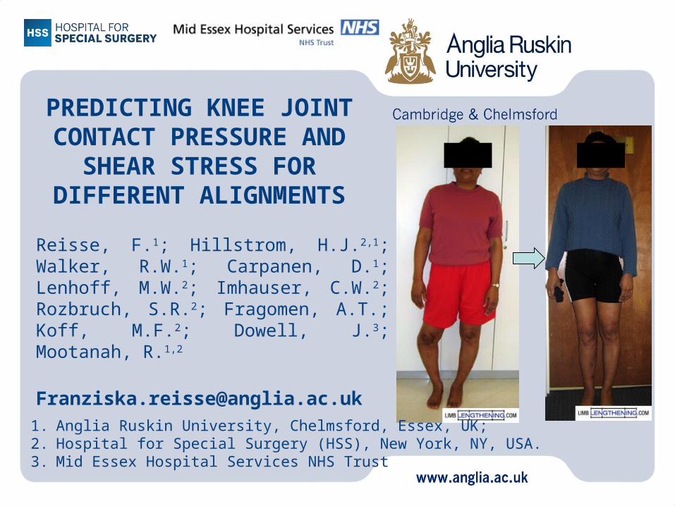
PREDICTING KNEE JOINT CONTACT PRESSURE AND
SHEAR STRESS FOR DIFFERENT ALIGNMENTS
Reisse, F.1; Hillstrom, H.J.2,1; Walker, R.W.1; Carpanen, D.1; Lenhoff, M.W.2; Imhauser, C.W.2; Rozbruch, S.R.2; Fragomen, A.T.; Koff, M.F.2; Dowell, J.3; Mootanah, R.1,2
0
1. Anglia Ruskin University, Chelmsford, Essex, UK; 2. Hospital for Special Surgery (HSS), New York, NY, USA.3. Mid Essex Hospital Services NHS Trust

Background
• Current targets:
MAD = 0mm
Fujisawa point
Gap in knowledge
Underlying link between the MAD and knee
joint contact mechanics is not well understood

Aim
• Determine the relationship between malalignment and the resulting knee joint contact mechanics
• Stress cannot be measured in vivo and the use of computational methods can yield useful information about joint mechanics.
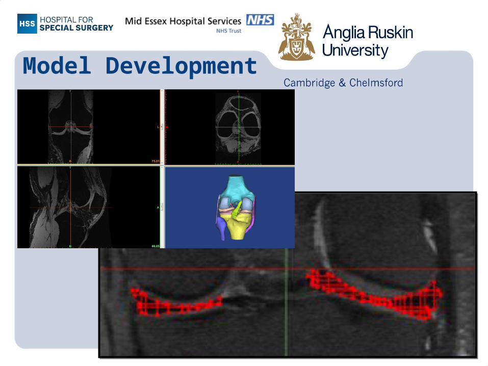
Model Development

3D model
anterior (front) view posterior (back) view

Constraint Definitions
Type Constraint
Perfect bonding Cartilage - Bones
Perfect bonding Ligaments - Bones
Perfect bonding Meniscal Horns – Tibia
Cartilage-cartilage and cartilage-meniscus interfaces were modelled as frictionless sliding

Boundary Conditions
Model validation, using 6 DOF robot:
1. Fix the proximal femur
2. Apply axial load at the distal tibia
3. Set constraints:
•Flx/ext constrained in sagittal plane
• Other degrees of freedom free
4. Apply different bending moments

Cadaveric study to validate
finite element models
Cadaveric specimen in 6 degree of freedom robot
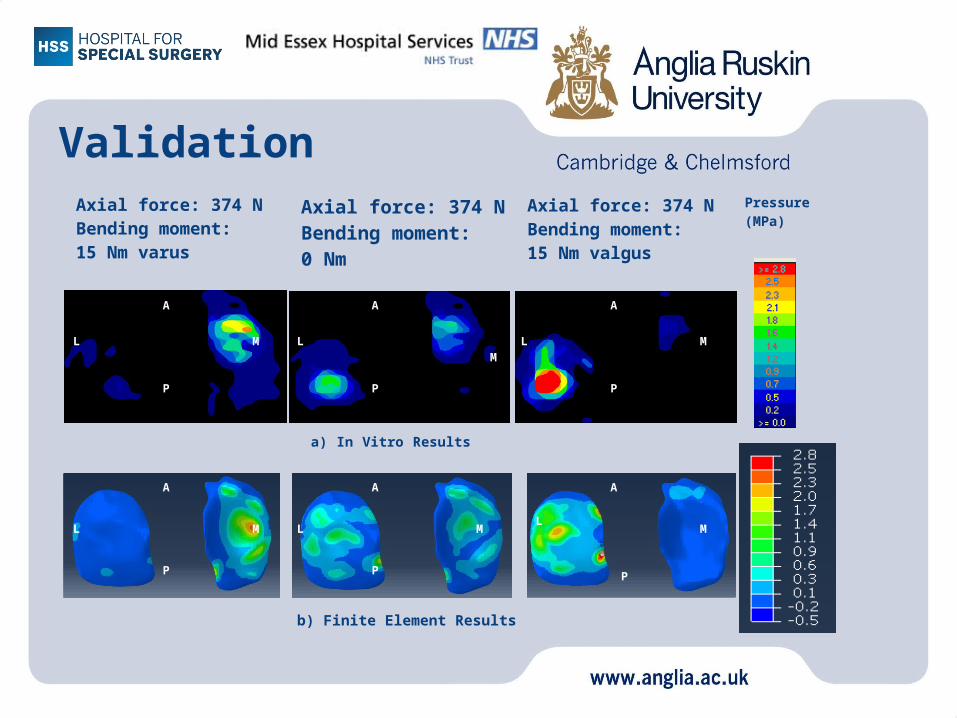
ValidationAxial force: 374 NBending moment: 15 Nm varus
Axial force: 374 NBending moment: 0 Nm
Axial force: 374 NBending moment: 15 Nm valgus
A
A
A
P
P
P
M
M M
L
L
L
A
A
A
P
P
P
M
M
M
L
L
L
a) In Vitro Results
b) Finite Element Results
Pressure (MPa)

Validation
%FSE medial:
•6.67%
%FSE lateral:
•5.94%
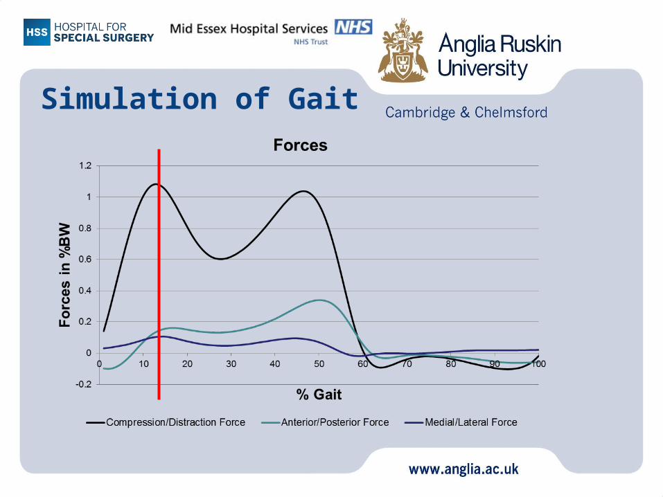
Simulation of Gait
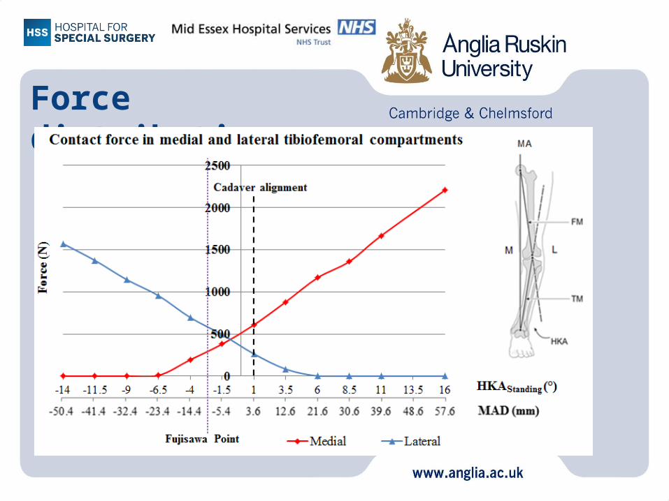
Force distribution
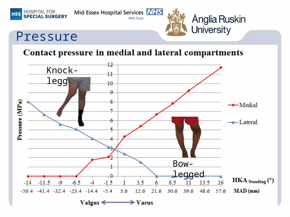
Pressure
Knock-legged
Bow-legged

Shear stress

Summary
• Minimum peak contact pressure occurred at an MAD of -1.44 mm and a corresponding HKA angle of 0.5° valgus
• Minimum peak shear stress occurred at an MAD of 3.6 mm and a corresponding HKA angle of 2.5° valgus

Discussion
• A computational model has been developed to predict stress and force as a function of malalignment prior to surgery
• Understanding the link between malalignment and knee joint stress will help improve surgical outcomes

Future Improvement
• Computational model generalisation, using 10 knees – Three year Arthritis Research UK funding

• This research was gratefully funded by the Chelmsford Medical Education and Research Trust
Acknowledgements