predictability in orbital reconstruction - uva · predictability in orbital reconstruction general...
TRANSCRIPT
UvA-DARE is a service provided by the library of the University of Amsterdam (http://dare.uva.nl)
UvA-DARE (Digital Academic Repository)
Predictability in orbital reconstruction
Dubois, L.
Link to publication
Citation for published version (APA):Dubois, L. (2016). Predictability in orbital reconstruction
General rightsIt is not permitted to download or to forward/distribute the text or part of it without the consent of the author(s) and/or copyright holder(s),other than for strictly personal, individual use, unless the work is under an open content license (like Creative Commons).
Disclaimer/Complaints regulationsIf you believe that digital publication of certain material infringes any of your rights or (privacy) interests, please let the Library know, statingyour reasons. In case of a legitimate complaint, the Library will make the material inaccessible and/or remove it from the website. Please Askthe Library: http://uba.uva.nl/en/contact, or a letter to: Library of the University of Amsterdam, Secretariat, Singel 425, 1012 WP Amsterdam,The Netherlands. You will be contacted as soon as possible.
Download date: 13 Jun 2018

PREDICTABILITY IN ORBITAL RECONSTRUCTION
LEANDER DUBOIS
PRED
ICTA
BILITY IN ORBITA
L REC
ON
STRUC
TION L
EAN
DER D
UBO
IS
39372 Dubois Omslag en kaarten.indd 1 04-03-16 12:16

Predictability in Orbital recOnstructiOn
Leander DuboisAmsterdam, 2016
39372 Dubois, Leander.indd 1 04-03-16 10:19
Publication of this thesis was generously supported by:KLS Martin GmbH Co., Mectron, 4 Dental tandtechniek, Xilloc Medical, NVMKA, ACTA, KNMT, Dam Medical, Dent-Med Materials (Geistlich Bio-Oss and Bio-Gide), Ortholab BV, Isseldent tandtechniek, Henry Schein, Strauman, Raadgevers, Exam Vision, Hu Friedy, OMFS Wisdom BV
ISBN 978-90-6464-992-9
Design: Ferdinand van Nispen tot Pannerden, Citroenvlinder DTP&Vormgeving, my-thesis.nl
Printed by: GVO Drukkers en vormgevers, Ede, The Netherlands
Copyright © 2016 Leander DuboisAll rights reserved. No part of this thesis may be reproduced, stored in a retrieval system or transmitted in any form or by any means without prior permission of the author.
39372 Dubois, Leander.indd 2 04-03-16 10:19

Predictability in Orbital recOnstructiOn
ACADEMISCH PROEFSCHRIFT
ter verkrijging van de graad van doctor aan de Universiteit van Amsterdam op gezag van de Rector Magnificus
prof. dr. D.C. van den Boom ten overstaan van een door het College voor Promoties ingestelde commissie,
in het openbaar te verdedigen in de Aula der Universiteit op vrijdag 3 juni 2016, te 13:00 uur
door Leander Dubois geboren te Leiden
39372 Dubois, Leander.indd 3 15-03-16 15:57

Promotiecommissie:
Promotoren: prof. dr. A.G. Becking Universiteit van Amsterdam prof. dr. J. de Lange Universiteit van Amsterdam
Copromotoren: dr. T.J.J. Maal Radboud Universiteit Nijmegen dr. P.J.J. Gooris Universiteit van Amsterdam
Overige leden: prof. dr. S.J. Bergé Radboud Universiteit Nijmegen prof. dr. J.C. Goslings Universiteit van Amsterdam prof. dr. M.P. Mourits Universiteit van Amsterdam prof. dr. F.R. Rozema Universiteit van Amsterdam prof. dr. D.B. Tuinzing Vrije Universiteit Amsterdam prof. dr. E.B. Wolvius Erasmus Universiteit Rotterdam
FACULTEIT DER TANDHEELKUNDE
39372 Dubois, Leander.indd 4 04-03-16 10:19

Contents
Chapter 1 General introduction and outline 7
Chapter 2 Controversies 172.1 Defect driven orbital reconstruction 192.2 Timing of post-traumatic orbital reconstruction 372.3 Biomaterials for orbital reconstruction 53
Chapter 3 Diagnostics 77How reliable is the visual appraisal of a surgeon for diagnosing orbital fractures?
79
Chapter 4 Predictability 994.1 Orbital Implant Dislocation Frame 1014.2 Endoscopic assisted orbital reconstruction 1194.3 Navigation assisted orbital reconstruction 135
Chapter 5 Advanced solutions 1515.1 Implant-oriented navigation 1535.2 Patient Specific Implants (PSIs) 165
Chapter 6 General discussion and conclusions 177
Chapter 7 Appendices 1877.1 Summary 1897.2 Samenvatting 1977.3 Dankwoord 205
List of co-authors 2147.4 Curriculum vitae 215
39372 Dubois, Leander.indd 5 04-03-16 17:44

39372 Dubois, Leander.indd 6 04-03-16 10:19

CHAPTER 1General Introduction and Outline
39372 Dubois, Leander.indd 7 04-03-16 10:19
Chapter 1
8
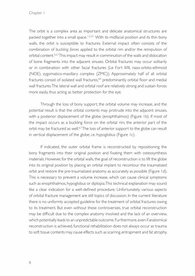
The orbit is a complex area as important and delicate anatomical structures are packed together into a small space.1,2,3,4 With its midfacial position and its thin bony walls, the orbit is susceptible to fractures. External impact often consists of the combination of buckling forces applied to the orbital rim and/or the retropulsion of orbital content.5,6,7 This impact may result in comminution of the walls and dislocation of bone fragments into the adjacent sinuses. Orbital fractures may occur solitarily or in combination with other facial fractures (Le Fort II/III, naso-orbito-ethmoid (NOE), zygomatico-maxillary complex (ZMC)). Approximately half of all orbital fractures consist of isolated wall fractures,8,9 predominantly orbital floor and medial wall fractures. The lateral wall and orbital roof are relatively strong and sustain forces more easily, thus acting as better protection for the eye.
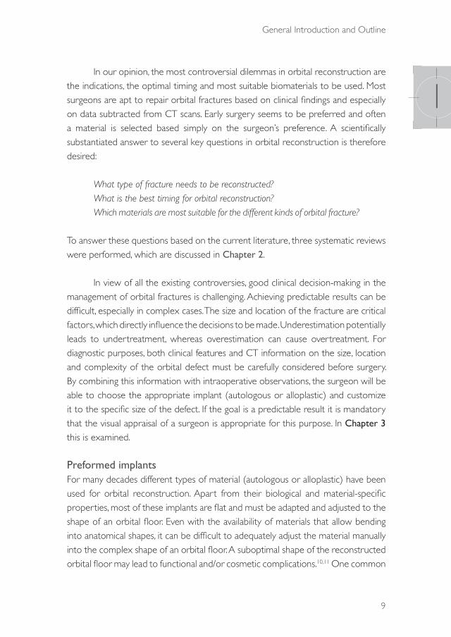
Through the loss of bony support, the orbital volume may increase, and the potential result is that the orbital contents may protrude into the adjacent sinuses, with a posterior displacement of the globe (enophthalmos) (Figure 1b). If most of the impact occurs as a buckling force on the orbital rim, the anterior part of the orbit may be fractured as well.6,7 The loss of anterior support to the globe can result in vertical displacement of the globe, i.e. hypoglobus (Figure 1c).
If indicated, the outer orbital frame is reconstructed by repositioning the bony fragments into their original position and fixating them with osteosynthesis materials. However, for the orbital walls, the goal of reconstruction is to lift the globe into its original position by placing an orbital implant to recontour the traumatized orbit and restore the pre-traumatized anatomy as accurately as possible (Figure 1d). This is necessary to prevent a volume increase, which can cause clinical symptoms such as enophthalmos, hypoglobus or diplopia. This technical explanation may sound like a clear indication for a well-defined procedure. Unfortunately, various aspects of orbital fracture management are still topics of discussion. In the current literature there is no uniformly accepted guideline for the treatment of orbital fractures owing to its treatment. But even without these controversies, true orbital reconstruction may be difficult due to the complex anatomy involved and the lack of an overview, which potentially leads to an unpredictable outcome. Furthermore, even if anatomical reconstruction is achieved, functional rehabilitation does not always occur as trauma to soft tissue contents may cause effects such as scarring, entrapment and fat atrophy.
39372 Dubois, Leander.indd 8 04-03-16 10:19
General Introduction and Outline
9
1In our opinion, the most controversial dilemmas in orbital reconstruction are
the indications, the optimal timing and most suitable biomaterials to be used. Most surgeons are apt to repair orbital fractures based on clinical findings and especially on data subtracted from CT scans. Early surgery seems to be preferred and often a material is selected based simply on the surgeon’s preference. A scientifically substantiated answer to several key questions in orbital reconstruction is therefore desired:
What type of fracture needs to be reconstructed? What is the best timing for orbital reconstruction? Which materials are most suitable for the different kinds of orbital fracture?
To answer these questions based on the current literature, three systematic reviews were performed, which are discussed in Chapter 2.
In view of all the existing controversies, good clinical decision-making in the management of orbital fractures is challenging. Achieving predictable results can be difficult, especially in complex cases. The size and location of the fracture are critical factors, which directly influence the decisions to be made. Underestimation potentially leads to undertreatment, whereas overestimation can cause overtreatment. For diagnostic purposes, both clinical features and CT information on the size, location and complexity of the orbital defect must be carefully considered before surgery. By combining this information with intraoperative observations, the surgeon will be able to choose the appropriate implant (autologous or alloplastic) and customize it to the specific size of the defect. If the goal is a predictable result it is mandatory that the visual appraisal of a surgeon is appropriate for this purpose. In Chapter 3 this is examined.
Preformed implantsFor many decades different types of material (autologous or alloplastic) have been used for orbital reconstruction. Apart from their biological and material-specific properties, most of these implants are flat and must be adapted and adjusted to the shape of an orbital floor. Even with the availability of materials that allow bending into anatomical shapes, it can be difficult to adequately adjust the material manually into the complex shape of an orbital floor. A suboptimal shape of the reconstructed orbital floor may lead to functional and/or cosmetic complications.10,11 One common
39372 Dubois, Leander.indd 9 14-03-16 09:24
Chapter 1
10
complication is enophthalmos. Recent studies showed that enophthalmos is more than just an increase of orbital volume.11,12 To reconstruct the proper geometry of the fractured walls an optimally shaped implant is required. Pre-bent meshes have been introduced to ease intraoperative adaptation and to improve the exact fit. Their versatility and cost make these implants even more advantageous .13-18 Andrades et al.17 concluded that pre-bent titanium implants are superior in terms of optimal reconstruction in comparison with flat, free-handedly bent implants, and result in a better clinical outcome. In large defects (Jaquiéry III-IV),19 the implant contour becomes an increasingly important factor for repositioning the globe in the correct position.
Figure 1. a.) normal situation b.) enopthalmos through increase of orbital volume c.) hypoglobus with loss of anterior support d.) repositioning the globe after orbital reconstruction
39372 Dubois, Leander.indd 10 14-03-16 09:24

General Introduction and Outline
11
1An additional advantage of a preformed implant is that a stereolithographic
(stl) software file of the implant can be used preoperatively to determine presurgically the optimal fit and position in a digital environment. This may help the surgeon to address the differences between the realised implant position and the optimal implant position. The effect of different methods of implant placement still needs to be scientifically compared and addressed. In Section 4.1, Chapter 4, this proof of principle is addressed to quantify the realised implant position and deliver a track record for the surgeon.
Benefits of endoscopy in orbital reconstructionOne of the most common reasons for suboptimal implant placement is the inability to define the posterior orbital ledge accurately, especially in larger orbital defects (Jacquiery III and IV).19 Implant placement on the ledge is important to ensure posterior support.
Once located, the ledge must be cleared of soft tissue, while the adjacent orbital fat and optic nerve must remain undisturbed.20 With a lack of overview and disrupted anatomy, visualization may be difficult during repositioning of the prolapsed orbital tissue out of the adjacent sinuses into the orbit before placement of the implant. In the literature it has been suggested by various authors that trans-sinusoidal endoscopy offers excellent visualization of the orbital floor, including the posterior ledge. The maxillary sinus is reported to provide a confined surgical space that allows visual confirmation of accurate implant placement.20-22 In Section 4.2, Chapter 4, conventional transconjunctival orbital reconstruction is compared with endoscopically assisted orbital reconstruction by using a cadaver model.
Computer-assisted surgeryComputer-assisted surgery (CAS) includes a preoperative diagnostic and planning phase, an intraoperative image-guided navigation phase, and an intra- or postoperative evaluation phase. The first phase allows the surgeon to use all the information in the Digital Imaging and Communications in Medicine (DICOM) dataset. The original anatomy can be digitally reconstructed using segmentation and mirroring tools.23 This information is beneficial for optimizing diagnostics and contributes to the surgeon’s preparation for the actual surgical procedure. Stereolithographic (stl) models of pre-bent or patient-specific implants can be fitted in this digital environment. After the
39372 Dubois, Leander.indd 11 14-03-16 09:24
Chapter 1
12
patient has been calibrated with the preoperative planning, with surface matching or screws/splints, the second phase can be started: image-guided navigation. The surgical goals are created in the preoperative planning phase and are checked intra-operatively during the navigation phase. Image-guided navigation can be regarded as target surgery. In this way, computer-assisted preoperative planning and surgery may enhance the predictability of the outcome through increased exploitation of radiologic information without additional radiation to the patient.24 Recent publications have suggested that CAS may increase the degree of accuracy in the treatment of orbital deformities.11,15,25-28 Unfortunately, all these studies are case series lacking a control group. In Section 4.3, Chapter 4, the effect of computer-assisted surgery is compared with the traditional approach to orbital reconstruction.
Object-oriented navigationNavigation-assisted surgery is comparable to well-known car navigation. It offers virtual information on the position of surgical instruments on radiographic data, in a 2D or 3D reconstructed environment. Together with the use of preoperative planning, the navigation system helps the surgeon to reach a target and it then offers optimal orientation in the surgical area.
The concept of object-oriented navigation is an interesting one for development. It involves the visualization of an object (as an stl file) in real time by combining computer-assisted planning and surgery with digital stereolithography and 3D virtual reconstruction. It would enable the surgeon to dock a preformed implant, which will be identical to the stl implant, by means of real-time navigational guidance in its desired (preplanned) position.
In Section 5.1, Chapter 5, the proof of principle is explained and examined.
Patient-specific implants (PSIs)A next step in orbital wall reconstruction will be the application of patient-specific implants (PSIs). The World Health Organization has announced that PSIs will play an important role in daily medical routines and potentially may replace conventional implants by 2020. Titanium laser-sintered PSIs for the reconstruction of orbital floor and wall fractures have only been available in the last few years. Computer-assisted surgery represents a key step towards safer practice and has become a standard technique during the past few years, allowing virtual surgery planning, simulation
39372 Dubois, Leander.indd 12 04-03-16 10:19
General Introduction and Outline
13
1and intraoperative control.23,27 PSIs allow for the precise reconstruction of orbital fractures by means of a complete digital workflow as in computer-assisted surgery. Adding PSIs for complex orbital reconstruction potentially represents a ground-breaking advance in medical quality control. In Section 5.2, Chapter 5, the use of PSIs is shown in a clinical cohort and is critically reviewed.
The ultimate goal of this thesis is to evaluate comprehensively and critically all the different modern diagnostic and treatment modalities in orbital reconstruction in order to estimate their reproducibility and predictability.
39372 Dubois, Leander.indd 13 04-03-16 10:19

Chapter 1
14
references
1. Turvey T, Golden BA. Orbital anatomy for the surgeon. Oral Maxillofac Surg Clin North Am. 2012: 24: 525-36.
2. Evans BT, Webb AA. Post-traumatic orbital reconstruction: anatomical landmarks and the concept of the deep orbit. Br J Oral Maxillofac Surg. 2007 :45: 183-9.
3. Cornelius CP, Mayer P, Ehrenfeld M, Metzger MC. The orbits-anatomical features in view of innovative surgical methods. Facial-plastic Surg 2014: 30: 487-508.
4. Koornneef L, Los JA. A new anatomical approach to the human orbit. Mod Probl Ophthalmol. 1975: 14: 49-56.
5. Warwar RE, Bullock JD, Ballal DR, Ballal RD. Mechanisms of orbital floor fractures: a clinical, experimental, and theoretical study. Ophthal Plast Reconstr Surg. 2000:16 : 188-200.
6. Schaller A, Huempfner-Hierl H, Hemprich A, Hierl T. Biomechanical mechanisms of orbital wall fractures – a transient finite element analysis. J Craniomaxillofac Surg. 2013: 41: 710-7.
7. Birkenfeld F, Steiner M, Becker ME, et al. Forces charging the orbital floor after orbital trauma. J Craniofac Surg. 2012: 23 : 953-6.
8. Siniković B, Kramer F-J, Swennen G, Lübbers H-T, Dempf R. Reconstruction of orbital wall defects with calcium phosphate cement: clinical and histological findings in a sheep model. Int J Oral Maxillofac Surg. 2007: 6: 54-61.
9. Bartoli D, Fadda MT, Battisti A, et al. Retrospective analysis of 301 patients with orbital floor fracture. J Craniomaxillofac Surg. 2015: 43: 244-7.
10. Rana M, Essig H, Rücker M, Ruecker M, Gellrich N-C. Development and demonstration of a novel computer planning solution for predefined correction of enophthalmos in anophthalmic patients using prebended 3D titanium-meshes – a technical note. J Oral Maxillofac Surg. 2012:70: 631-8.
11. Rana M, Chui CH, Wagner M, et al. Increasing the accuracy of orbital reconstruction with selective laser-melted patient-specific implants combined with intraoperative navigation. J Oral Maxillofac Surg. 2015: 73: 1113-8.
12. Kamer L, Noser H, Schramm A, Hammer B. Orbital form analysis: problems with design and positioning of precontoured orbital implants: a serial study using post-processed clinical CT data in unaffected orbits. Int J Oral Maxillofac Surg. 2010: 39: 666-72.
13. Strong EB, Fuller SC, Wiley DF, Zumbansen J, Wilson MD, Metzger MC. Preformed vs intraoperative bending of titanium mesh for orbital reconstruction. Otolaryngol Head Neck Surg. 2013: 149: 60-6.
14. Metzger MC, Hohlweg-Majert B, Schön R, et al. Verification of clinical precision after computer-aided reconstruction in craniomaxillofacial surgery. Oral Surg Oral Med Oral Pathol Oral Radiol Endod. 2007: 104: 1-10.
15. Metzger MC, Schön R, Zizelmann C, Weyer N, Gutwald R, Schmelzeisen R. Semiautomatic procedure for individual preforming of titanium meshes for orbital fractures. Plast Reconstr Surg. 2007: 119: 969-76.
16. Scolozzi P, Momjian A, Heuberger J, et al. Accuracy and predictability in use of AO three-dimensionally preformed titanium mesh plates for posttraumatic orbital reconstruction: a pilot study. J Craniofac Surg. 2009: 20: 1108-13.
17. Andrades P, Hernandez D, Falguera MI, et al. Degrees of tolerance in post-traumatic orbital volume correction: the role of prefabricated mesh. J Oral Maxillofac Surg. 2009: 67: 2404-11.
18. Huempfner-Hierl H, Doerfler H-M, Kruber D, Hierl T. Morphologic comparison of preformed orbital meshes. J Oral Maxillofac Surg. 2015: 73: 1119-23.
19. Jaquiéry C, Aeppli C, Cornelius P, Palmowsky A, Kunz C, Hammer B. Reconstruction of orbital wall defects: critical review of 72 patients. Int J Oral Maxillofac Surg. 2007: 36: 193-9.
20. Kakibuchi M, Fukazawa K, Fukuda K, et al. Combination of transconjunctival and endonasal-transantral approach in the repair of blowout fractures involving the orbital floor. Br J Plast Surg. 2004: 57: 37-44.
21. Strong EB. Endoscopic repair of orbital blow-out fractures. Oper Tech Otolaryngol Neck Surg. 2006: 17: 201-9.
22. Hundepool AC, Willemsen MAP, Koudstaal MJ, van der Wal KGH. Open reduction versus endoscopically controlled reconstruction of orbital floor fractures: a retrospective analysis. Int J Oral Maxillofac Surg. 2012: 41: 489-93.
39372 Dubois, Leander.indd 14 04-03-16 10:19

General Introduction and Outline
15
123. Schramm A, Suarez-Cunqueiro MM, Rücker M, et al. Computer-assisted therapy in orbital and mid-facial
reconstructions. Int J Med Robotics. 2009; 5: 111-124.
24. Gellrich N-C, Schramm A, Hammer B, et al. Computer-assisted secondary reconstruction of unilateral posttraumatic orbital deformity. Plast Reconstr Surg. 2002: 110: 1417-29.
25. Markiewicz MR, Dierks EJ, Bell RB. Does intraoperative navigation restore orbital dimensions in traumatic and post-ablative defects? J Craniomaxillofac Surg. 2012: 40: 142-8.
26. Markiewicz MR, Dierks EJ, Potter BE, Bell RB. Reliability of intraoperative navigation in restoring normal orbital dimensions. J Oral Maxillofac Surg. 2011: 69: 2833-40.
27. Essig H, Dressel L, Rana M, et al. Precision of posttraumatic primary orbital reconstruction using individually bent titanium mesh with and without navigation: a retrospective study. Head Face Med. 2013: 9: 18.
28. Yu H, Shen SG, Wang X, Zhang L, Zhang S. The indication and application of computer-assisted navigation in oral and maxillofacial surgery – Shanghai’s experience based on 104 cases. J Craniomaxillofac Surg. 2013: 41: 770-4.
39372 Dubois, Leander.indd 15 04-03-16 10:19

39372 Dubois, Leander.indd 16 04-03-16 10:19

CONTROVERSIES
39372 Dubois, Leander.indd 17 04-03-16 10:19

39372 Dubois, Leander.indd 18 04-03-16 10:19

CHAPTER 21
Defect driven orbital reconstruction
This chapter is an edited version of the manuscript: Dubois L, Steenen SA, Gooris PJJ, Mourits MP, Becking AG:
Controversies in orbital reconstruction-I. Defect-driven orbital reconstruction: A systematic review. Int J Oral Maxillofac Surg 2015: 44: 308-315.
39372 Dubois, Leander.indd 19 04-03-16 10:19
Chapter 21
20
intrOductiOn
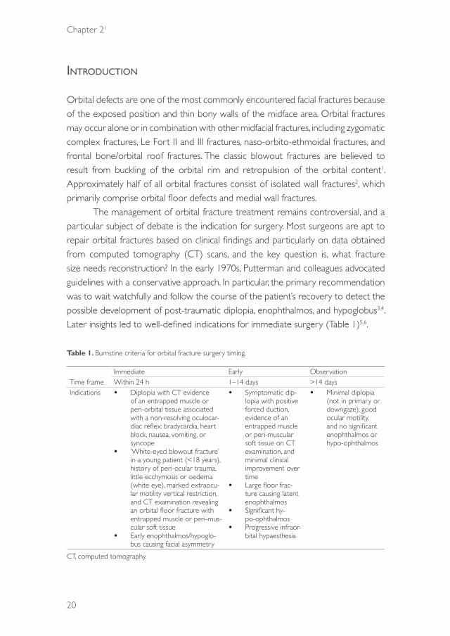
Orbital defects are one of the most commonly encountered facial fractures because of the exposed position and thin bony walls of the midface area. Orbital fractures may occur alone or in combination with other midfacial fractures, including zygomatic complex fractures, Le Fort II and III fractures, naso-orbito-ethmoidal fractures, and frontal bone/orbital roof fractures. The classic blowout fractures are believed to result from buckling of the orbital rim and retropulsion of the orbital content1. Approximately half of all orbital fractures consist of isolated wall fractures2, which primarily comprise orbital floor defects and medial wall fractures.
The management of orbital fracture treatment remains controversial, and a particular subject of debate is the indication for surgery. Most surgeons are apt to repair orbital fractures based on clinical findings and particularly on data obtained from computed tomography (CT) scans, and the key question is, what fracture size needs reconstruction? In the early 1970s, Putterman and colleagues advocated guidelines with a conservative approach. In particular, the primary recommendation was to wait watchfully and follow the course of the patient’s recovery to detect the possible development of post-traumatic diplopia, enophthalmos, and hypoglobus3,4. Later insights led to well-defined indications for immediate surgery (Table 1)5,6.
Table 1. Burnstine criteria for orbital fracture surgery timing.
Time frameImmediate Early ObservationWithin 24 h 1–14 days >14 days
Indications • Diplopia with CT evidence of an entrapped muscle or peri-orbital tissue associated with a non-resolving oculocar-diac reflex: bradycardia, heart block, nausea, vomiting, or syncope
• ‘White-eyed blowout fracture’ in a young patient (<18 years), history of peri-ocular trauma, little ecchymosis or oedema (white eye), marked extraocu-lar motility vertical restriction, and CT examination revealing an orbital floor fracture with entrapped muscle or peri-mus-cular soft tissue
• Early enophthalmos/hypoglo-bus causing facial asymmetry
• Symptomatic dip-lopia with positive forced duction, evidence of an entrapped muscle or peri-muscular soft tissue on CT examination, and minimal clinical improvement over time
• Large floor frac-ture causing latent enophthalmos
• Significant hy-po-ophthalmos
• Progressive infraor-bital hypaesthesia
• Minimal diplopia (not in primary or downgaze), good ocular motility, and no significant enophthalmos or hypo-ophthalmos
CT, computed tomography.
39372 Dubois, Leander.indd 20 04-03-16 10:19

Controversies
21
21
Strong indications for immediate repair include (1) diplopia with radiological evidence of compressed orbital tissue resulting in early ischemic necrosis and oculocardiac reflex7,8, (2) life-threatening white-eyed blowouts or trapdoor fractures in children with eye motility disturbances, and (3) radiological evidence of orbital tissue compression9,10 accompanied by oculocardiac reflex, early enophthalmos, or hypoglobus producing facial asymmetry that affects function and cosmesis11,12. In addition, to prevent the fibrosis of injured orbital tissue, early repair within 2 weeks has been proposed for some indications, such as clinically unimproved diplopia with radiological evidence of orbital tissue compression13. Further, several studies have shown that early reconstruction of large orbital defects is essential for good functional results14–16. The most difficult management decisions occur with patients with smaller orbital defects. For example, patients with orbital fractures who have good ocular motility and only slight displacement of the orbital content are often treated expectantly. Estimating the benefit of surgery in these cases is challenging, since the behaviour of the soft tissues over time is unpredictable. Thus, the indication for surgical intervention in these types of cases remains controversial.
The clinical outcomes of treatment for the different types of orbital fracture are difficult to compare. The decision to choose a certain implant material must be based on the size and location of the defect and the remaining structural support in combination with clinical symptomatology17. In the case of linear fractures with small defects and entrapment of the orbital content, the placement of a membrane may be suitable, whereas in larger defects affecting one wall or multiple walls, a stronger, supportive material may be necessary18.
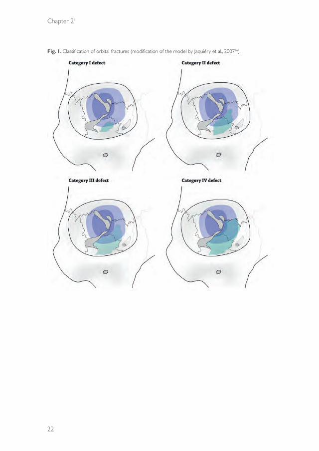
Jaquiéry et al.16 proposed a simplified two-dimensional model to describe these fractures semi-quantitatively in a trefoil-shaped diagram of the internal orbit. Five categories of the extent of the fracture were defined; fractures with a higher classification were associated with a lower accuracy of reconstruction due to repositioning of the globe (Fig. 1). In our experience, the current process of surgical decision-making is rarely influenced by this classification.
The aim of this study was to systematically review all prospective and retrospective clinical trials on orbital reconstruction. Particular focus was placed on the indication for surgery in relation to defect size and location, in order to identify the reconstruction methods that show the best results for the different types of orbital fracture.
39372 Dubois, Leander.indd 21 04-03-16 10:19
Chapter 21
22
Fig. 1. Classification of orbital fractures (modification of the model by Jaquiéry et al., 200716).
39372 Dubois, Leander.indd 22 04-03-16 10:19

Controversies
23
21
MethOds
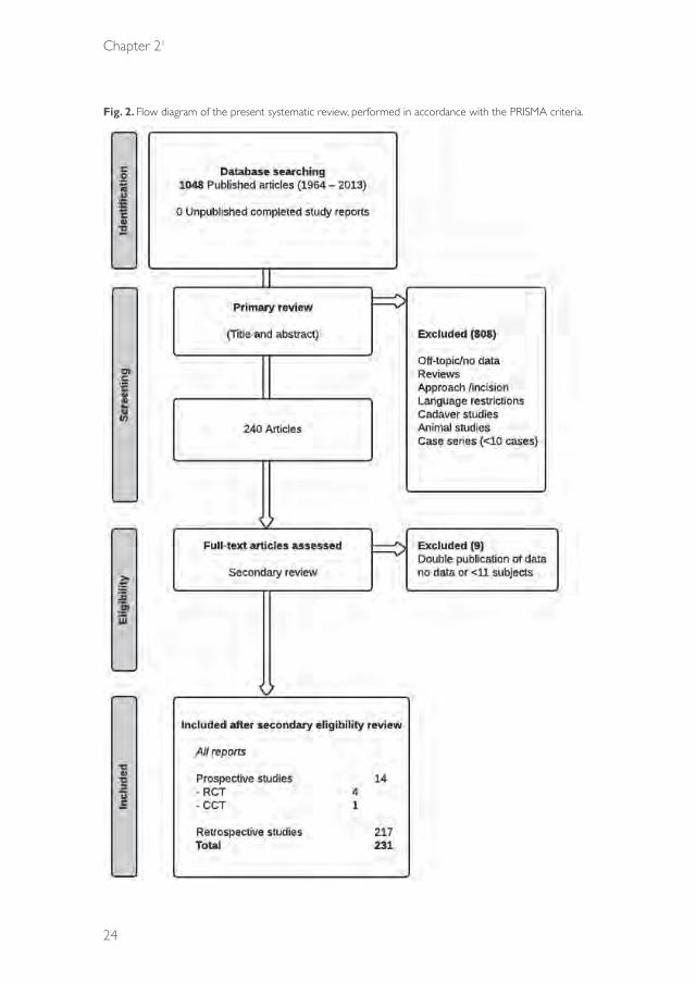
A systematic literature search in PubMed (updated until 4 October 2013; all indexed years) was performed using multiple search terms, combining the subjects ‘orbital fracture’, ‘reconstruction material’, ‘volume’, and ‘classification’. The search excluded case series with 10 or fewer subjects. The language was restricted to English and German. All human clinical studies (prospective and retrospective) on various surgical reconstruction methods used for orbital fracture treatments met our entry criteria. Preclinical animal and cadaveric studies, as well as clinical studies comparing different incisions or approaches rather than reconstruction methods, were excluded. Fig. 2 shows a flow diagram of the inclusion process. Two authors (SS and LD) appraised the relevance of the articles based on the abstracts (in a primary review process, according to the PRISMA criteria (Preferred Reporting Items for Systematic Reviews and Meta-Analyses)). In a secondary review, full articles were retrieved, and relevant articles were included. Disagreement was resolved through discussion with a third person (PG).
The PubMed search terms were as follows: (((((“Orbital Fractures”[Mesh])) OR (orbital fracture*[tiab] OR orbit fracture*[tiab] OR orbital trauma*[tiab] OR orbit trauma*[tiab] OR orbital injur*[tiab] OR orbit injur*[tiab] OR orbital wall fracture*[tiab] OR orbital wall injur*[tiab] OR orbital wall trauma*[tiab] OR orbital floor fracture*[tiab] OR orbital floor injur*[tiab] OR orbital floor trauma*[tiab] OR blow-out fracture*[tiab] OR blowout fracture*[tiab] OR supraorbital fracture*[tiab] OR trapdoor fracture*[tiab] OR malar fracture*[tiab] OR tripod fracture*[tiab] OR orbitozygomatic fracture*[tiab] OR orbito-zygomatic fracture*[tiab] OR zygomatico-orbital fracture*[tiab] OR zygomaticoorbital fracture*[tiab] OR tripartite fracture*[tiab] OR (le fort[tiab] AND fracture*[tiab]) OR (lefort[tiab] AND fracture*[tiab])))) AND ((“Prostheses and Implants”[Mesh] OR prosthes*[tiab] OR implant*[tiab]) OR (“Internal Fixators”[Mesh] OR internal fixat*[tiab] OR plate*[tiab] OR reconstruct*[tiab] OR membrane*[tiab] OR sheet*[tiab] OR mesh*[tiab]) OR (“Bone Transplantation”[Mesh] OR bone transplant*[tiab] OR bone graft*[tiab] OR “Cartilage”[Mesh] OR cartilage[tiab] OR “Fascia Lata”[Mesh] OR fascia lata*[tiab] OR “Periosteum”[Mesh] OR periosteum*[tiab] OR “Dura Mater”[Mesh] OR dura[tiab] OR “Gelatin”[Mesh] OR gelatin[tiab] OR “Sclera”[Mesh] OR sclera*[tiab]) OR (“Biocompatible Materials”[Mesh] OR biomaterial*[tiab] OR bioceramic*[tiab] OR animal derived[tiab]) OR (“Durapatite”[Mesh] OR
39372 Dubois, Leander.indd 23 04-03-16 10:19
Chapter 21
24
Fig. 2. Flow diagram of the present systematic review, performed in accordance with the PRISMA criteria.
39372 Dubois, Leander.indd 24 04-03-16 10:19
Controversies
25
21
durapatite[tiab] OR hydroxyapatite[tiab] OR hydroxylapatite[tiab] OR bioactive glass[tiab] OR “Titanium”[Mesh] OR titanium[tiab] OR “Cobalt”[Mesh] OR cobalt[tiab] OR “Silicones”[Mesh] OR silicone*[tiab]) OR (“Polymers”[Mesh] OR polymer[tiab] OR polymers[tiab] OR polymeric[tiab] OR polyethylene*[tiab] OR nylon*[tiab] OR teflon[tiab] OR “poly(lactic acid)”[Supplementary Concept] OR “poly(lactic acid)”[tiab] OR polylactic acid[tiab] OR poly-d,l-lactic acid[tiab] OR poly-L-lactic acid[tiab] OR “poly(lactic-co-hydroxymethyl glycolic acid)”[Supplementary Concept] OR PLA/PGA[tiab] OR polydioxanone*[tiab] OR polyglactin 910[tiab]) OR (“Alloys”[Mesh] OR alloy*[tiab]))) NOT case reports[pt].
results
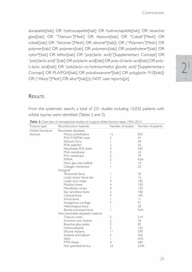
From the systematic search, a total of 231 studies including 15,032 patients with orbital injuries were identified (Tables 2 and 3).
Table 2. Overview of retrospective studies on surgical orbital fracture repair, 1964–2013.Fracture type Reconstruction materials Number of studiesa Number of patientsOrbital floor/pure blowout
Resorbable alloplastic Porous polyethylene PGA 910/PDA mesh Ethisorb Dura PDA plate/foil Resorbable PDS sheet PGA membrane PLA membrane PMMA Fibrin glue and scaffold Collagen membraneAutograft Temporalis fascia Lyoph. tensor fascia lata Lyoph. dura mater Maxillary bone Mandibular cortex Iliac cancellous bone Calvarial bone Antral bone Autogenous cartilage Heterologous bone Bovine processed boneNon-resorbable alloplastic material Titanium mesh Kirschner wire fixation Bioactive glass plates Hydroxylapatite Silicone implants Implants and balloon Stent PTFE sheets Not specified/various
12212422211
11444241711
52321151423
8244144264292479N/A1023
3212185150124106102119120N/A
2145685103590426N/A4402546
39372 Dubois, Leander.indd 25 04-03-16 10:19

Chapter 21
26
Table 2. ContinuedFracture type Reconstruction materials Number of studiesa Number of patientsOrbital floor and medial wall
Porous polyethyleneTitanium meshBone graftMandibular cortexCAD/CAM anatomical platesNylon foil ‘wraparound’Not specified/various
1311114
396841461598176
Medial wall Porous polyethyleneHydroxylapatiteCustomized titanium meshPGA 910/PDA meshNot specified/various
31114
18548223197
Lateral wall Bone graft 1 85Orbital roof PGA 910/PDA mesh
Not specified/various 14
85251
‘Large’, ‘extensive’, ‘complex’ or comminuted orbital fractures
Porous polyethyleneCAD/CAM titanium sheetsTitanium and LactoSorbTitanium implantsPLA/PGA plates and screwsBone graftsNot specified/various
3212112
198292065114989
Zygomatico-orbital fractures
Porous polyethyleneAutogenous conchal cartilageMaxillary wall graftHydroxylapatiteTitanium meshPlates and screwsNot specified/various
2111237
27527593112625
Heterogeneous/ mixed
MacroporeTitanium implantCAD/CAM titanium sheetsResorbable sheetsVitallium meshAutogenous graftBiodegradable plates and screwsBioactive glass platesPolyethylene + hydroxyapatiteX-ray film implantNot specified/various
1511218122116
10628414111764627429571450562019
Total 217 14,650Lyoph., lyophilized; N/A, not available; PDA, polydioxanone; PDS, poly-p-dioxanone; PGA, polyglycolic acid; PLA, polylactic acid; PTFE, polytetrafluoroethylene; PMMA, poly(methyl methacrylate).aSome studies present more than one type of reconstruction material.
39372 Dubois, Leander.indd 26 04-03-16 10:19
Controversies
27
21
Tabl
e 3.
Ove
rvie
w o
f pro
spec
tive
stud
ies
on s
urgi
cal o
rbita
l fra
ctur
e re
pair,
2001
–201
3.
Stud
y [R
ef.]
Des
ign
Indi
catio
n fo
r su
rger
yD
efec
t siz
eD
efec
t lo
catio
nRe
cons
truc
tion
mat
eria
lsN
umbe
r of
pa
tient
s
Follo
w-u
p (p
osto
p.)
Dip
lopi
a (a
ny
gaze
)En
opht
halm
os/
prop
tosis
/ dys
topi
aEy
e m
otilit
y di
sord
erIn
fra-
orbi
tal
hypa
esth
esia
Preo
p.Po
stop
.Pre
op.
Post
op.
Preo
p.Po
stop
.Pr
eop.
Post
op.
Krus
chew
sky
et
al., 2
011
[25]
RCT
Dec
reas
ed o
cula
r m
obilit
y; di
plop
ia;
enop
htha
lmos
; ocu
lar
func
tiona
l com
prom
ise
N/A
Fl
oor
±
med
ial w
all
± o
ther
faci
al
frac
ture
s
Aur
icul
ar c
artil
age
graf
t (8
) vs
. bl
ade
abso
rbab
le
poly
acid
co
poly
mer
(12
)
206
mon
ths
25%
vs.
42%
(P =
N
/A)
0% v
s. 0%
88%
vs.
83%
(P =
N
/A)
0% v
s. 0%
13%
vs.
8% (P =
N
/A)
0% v
s. 0%
38%
vs
. 42
%(P
=
N/A
)
25%
vs.
17%
(P
=
N/A
)
Beck
er e
t al
., 20
10 [
18]
RCT
Inca
rcer
ated
or
prol
apse
d or
bita
l tiss
ue
(CT)
<1
cmIso
late
d flo
or
(13)
as
soci
ated
zy
gom
atic
fr
actu
re (
11)
[
Col
lage
n m
embr
ane
(12)
vs
. PD
S fo
il 0.
15
mm
(12
)
24 (
20;
2 lo
st t
o fo
llow
-up
in
both
gr
oups
)
6 m
onth
s21
% o
f to
tal
0% v
s. 0%
0% v
s. 0%
0%
vs.
0%29
% o
f to
tal
0% v
s. 0%
60%
of
to
tal
0% o
f to
tal
Baya
t et
al.,
2010
[20
]RC
TEn
opht
halm
os <
2 m
m
N/A
Floo
r ±
m
edia
l wal
l ±
oth
er fa
cial
fr
actu
res
Nas
al s
epta
l ca
rtila
ge (
11)
vs.
conc
hal c
artil
age
(11)
223–
6 m
onth
s(P
=
NS)
9% v
s. 9%
(P =
N
S)Le
ss in
na
sal s
epta
l gr
oup
(P =
0.0
09)
(P =
N
S)(P
=
NS)
(P =
N
S)(P
=
NS)
Die
tz e
t al
., 20
01 [
26]
RCT
(mul
ti-ce
ntre
)
Incr
ease
d or
bita
l pr
essu
re; e
noph
thal
mos
; pe
rsist
ent
dipl
opia
; vi
sual
impa
irmen
t; hy
popa
rest
hesia
; IO
N;
seve
re d
isloc
atio
n (fr
actu
re g
ap >
3 cm
)
N/A
N
/APe
rfora
ted
PDS
foil
0.15
mm
(1
4) v
s. tit
aniu
m
dyna
mic
mes
h (1
4)
28>
6 m
onth
s75
% v
s. 88
%(P
=
N/A
)
50%
vs.
50%
79
% v
s. 86
%(P
=
N/A
)
86%
vs.
86%
75
% v
s. 88
%(P
=
N/A
)
50%
vs.
50%
10
%
vs. 9
%
N/A
Al-S
ukhu
n an
d Li
ndqv
ist, 2
006
[29]
CC
T>
2 cm
>2
cmFl
oor
±
med
ial w
all
Aut
ogen
ous
bone
gr
aft
(24)
vs.
PLA
70
/30
plat
e (1
5)
3936
wee
ks33
% v
s. 13
% (
P =
NS)
0% v
s. 7% (P
=
NS)
46%
vs.
20%
(P
= N
S)
13%
vs.
13%
(P =
NS)
21%
vs.
20%
(P =
N
S)
0% v
s. 0%
8% v
s. 7%
(P
= N
S)
0% v
s. 0%
Lieg
er e
t al
., 20
10 [
31]
Pilo
t w
ithou
t co
ntro
ls
>2
cm o
r >
1 w
all;
expe
ctin
g fu
nctio
nal o
r ae
sthe
tic d
efici
t
Jaqu
iéry
ca
tego
ry
III–I
Va
Floo
r ±
m
edia
l wal
lLo
w-p
rofil
e tit
aniu
m m
esh
2712
wee
ks25
–52
%26
%26
%11
%36
%14
%N
/AN
/A
Nod
a et
al.,
2011
[27
]Pi
lot
with
out
cont
rols
Pers
isten
t di
plop
ia
(<30
upw
ard
gaze
, <40
do
wnw
ard
gaze
)
Jaqu
iéry
ca
tego
ry
I–III
a
Line
ar (
2),
mid
dle
(7),
post
erio
r (6
)
Perio
stea
l sut
urin
g15
5–36
m
onth
s10
0%40
%N
/A0%
100%
40%
N/A
N/A
39372 Dubois, Leander.indd 27 04-03-16 10:19

Chapter 21
28
Tabl
e 3.
Con
tinue
d
Stud
y [R
ef.]
Des
ign
Indi
catio
n fo
r su
rger
yD
efec
t siz
eD
efec
t lo
catio
nRe
cons
truc
tion
mat
eria
lsN
umbe
r of
pa
tient
s
Follo
w-u
p (p
osto
p.)
Dip
lopi
a (a
ny
gaze
)En
opht
halm
os/
prop
tosis
/ dys
topi
aEy
e m
otilit
y di
sord
erIn
fra-
orbi
tal
hypa
esth
esia
Preo
p.Po
stop
.Pre
op.
Post
op.
Preo
p.Po
stop
.Pr
eop.
Post
op.
Waj
ih e
t al
., 201
1 [1
7 or
24]
Coh
ort
stud
yN
/AN
/AFl
oor
Aut
ogen
ous
graf
t (1
4) v
s. po
rous
po
lyet
hyle
ne (
12)
266
mon
ths
61%
11.5
%
vs.
26.9
%(P
=
1.24
)
50%
11.4
% v
s. 15
.3%
(P =
0.4
7)
39%
2.8%
vs.
7.7%
(P =
0.
574)
3.8%
pr
eop.
Folk
esta
d an
d G
rans
tröm
, 20
03 [
22]
Coh
ort
stud
yN
/AN
/AFl
oor
(51)
with
as
soci
ated
fa
cial
frac
ture
(4
5)
Vario
us51
12 m
onth
s33
%9.
5%11
%
16%
0%82
%
60%
po
stop
.(P
=
N/A
)
Kont
io e
t al
., 20
06 [
23]
Coh
ort
stud
yN
/AN
/AIso
late
d flo
or
(11)
and
flo
or w
ith
asso
ciat
ed
faci
al fr
actu
re
(13)
Iliac
cor
tex
245–
13
mon
ths
85%
0%19
%38
%
N/A
0%N
/AN
/A
Kont
io e
t al
., 20
01 [
23]
Coh
ort
stud
yD
efici
ency
in e
ye
mov
emen
ts; d
iplo
pia;
hypo
phth
alm
os;
enop
htha
lmos
N/A
PDS
impl
ant
1613
–46
wee
ks56
%25
%13
%38
%N
/AN
/A69
%6% (P
=
N/A
)
Scol
ozzi
et
al.,
2009
[30
]Pr
elim
inar
y C
CT
>2
cm d
efec
t; ev
iden
ce o
f sof
t tis
sue
entr
apm
ent
>2
cm
Non
-pre
form
ed
(1)
vs.
3D-p
refo
rmed
tit
aniu
m m
esh
plat
es
206–
12
mon
ths
N/A
N/A
N/A
N/A
N/A
N/A
N/A
N/A
Cai
et
al., 2
012
[21]
Mat
ched
co
ntro
l tr
ial
N/A
N
/AKo
libri
intr
aope
rativ
e na
viga
tion
devi
ce
(29)
vs.
cont
rols
(29)
5812
mon
ths
N/A
2% v
s. 10
%
(P =
0.
039)
N/A
3% v
s. 10
%(P
= N
S)N
/A3%
vs.
3%N
/A0%
vs.
4% (P =
N
S)
Fern
ande
s et
al.,
2007
[28
]C
ase
serie
s>
1.5
cm R
estr
ictio
n of
gaz
e su
gges
ting
entr
apm
ent;
dipl
opia
>1.
5 cm
Poly
ethy
lene
im
plan
t10
1–26
w
eeks
90%
11%
N/A
0%N
/A7%
0%0%
39372 Dubois, Leander.indd 28 04-03-16 10:19

Controversies
29
21
CCT, controlled clinical trial; CT, computed tomography; ION, infra-orbital nerve; N/A, not available; NS, not statistically significant; PDS, poly-p-dioxanone; PLA, poly-l/dl-lactide; RCT, randomized clinical trial.
aOrbital wall defect categorization by Jaquiéry et al., 200716. In cases where the studied category was unclear, the defect types are listed descriptively in this table.
Retrospective studiesThe majority of studies in the literature were retrospective in nature (94%; n = 217), providing either descriptive data on a single institution’s experience with a heterogeneous series of orbital fracture reconstructions, or describing uncontrolled data on a single treatment modality. The clinical and radiological outcome measurements of these studies were heterogeneous and sometimes subjective. Moreover, the complications were not always reported, and the follow-up periods were variable. The defect locations and sizes were often poorly specified. An overview of the surgical treatment of orbital fractures reported for all retrospective studies from 1964 to 2013 is shown in Table 2.
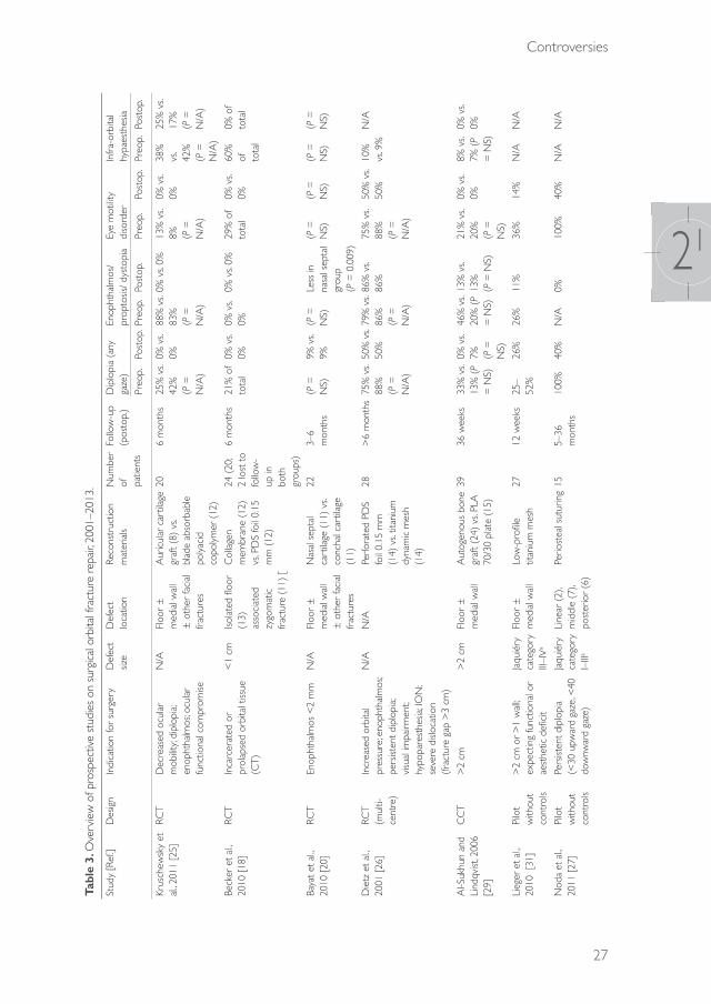
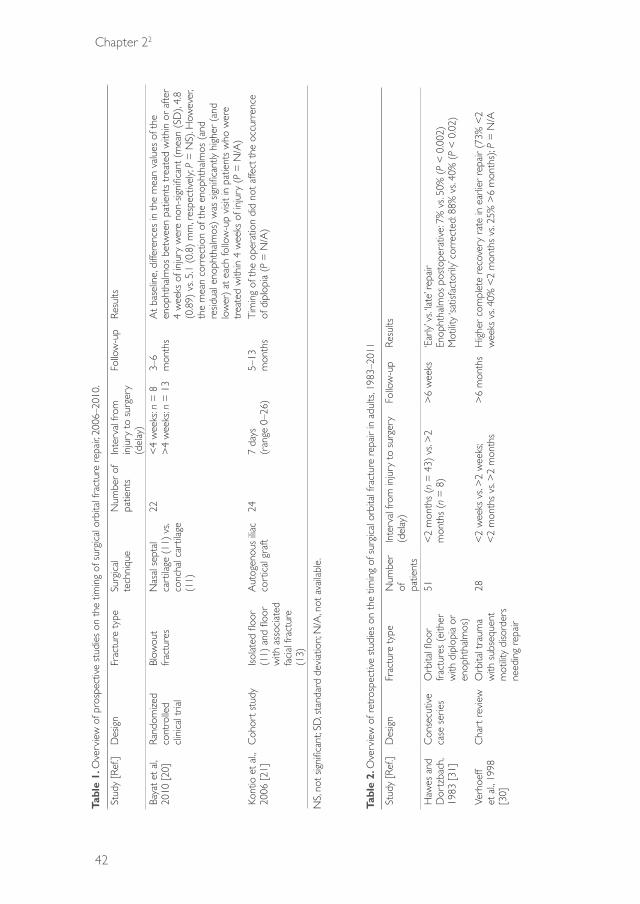
Prospective studiesAs shown in Table 3, 14 prospective studies were performed. Five of these were controlled clinical trials, of which four were randomized. In total, 380 orbital fractures were included in the prospective studies. The highest level of evidence was found in a randomized controlled trial by Bayat et al.20. This study showed a statistical difference only in the advantage of nasal cartilage over conchal cartilage as the best reconstructive material in preventing enophthalmos after 3–6 months of follow-up (P = 0.008). The remaining controlled clinical trials provided no statistically significant data. Descriptions of the actual defect size and location of the fractures were limited.
The indication for surgery was not described in four of the 14 prospective studies21–24. For the remaining studies, the reasons for surgical intervention were diverse. Although the Burnstine criteria were applied in several studies (Table 1)
5,6, most studies used less objective criteria. The clinical parameters of motility disturbance and diplopia were reported as an indication for intervention in only six studies23,24–28. Enophthalmos was an indication for surgery in four studies, but not all authors described the degree of enophthalmos20,24-26. The defect size (as measured by CT scan) was used as an indication for surgery in five studies26,28,29,30,31. Meanwhile, incarcerated or prolapsed orbital tissue in the maxillary sinus was the indication for intervention in two different reports18,30.
The defect size and location were mentioned in six of 14 studies18,27–31. Becker et al.18 focused on the reconstruction of small orbital defects (<1 cm). In the study
39372 Dubois, Leander.indd 29 04-03-16 10:19

Chapter 21
30
of Lieger et al.31, which used the Jaquiéry classification16, only large orbital defects were reconstructed.
discussiOn
In this systematic review, most of the studies showed substantial heterogeneity in the types and sizes of the orbital fractures, which might be due to limited case loads and the small number of patients available in these centres. In addition, the number of randomized controlled trials on orbital reconstruction was limited, and only one of these studies described both the defect size and localization in relation to the type of fracture18. Hence, because of the small sample sizes, the heterogeneity of groups, and the poor description of the defect sizes and locations, no solid evidence-based conclusions or guidelines can be drawn on defect-driven reconstruction. Further reproducible trials using multi-centre settings are needed to develop guidelines for defect-driven orbital reconstruction.
In the general treatment of skeletal fractures, a common concept is that the surgeon bases the decision regarding which hardware to use on the complexity of the fracture. For most fractures, classifications and treatment models have been established based on the fracture complexity, bony buttresses, and support32. However, in orbital fractures, the bony walls are generally comminuted and the parts are often useless for reconstruction. In contrast to other midfacial fractures, orbital defects need reconstruction rather than reduction and fixation of fragments, but the indication for this intervention is arbitrary. In some institutions, a surgical approach is advocated even in cases of small defects with no functional impairment, whereas in other centres, a non-surgical approach is the treatment of choice.
The strength of the reconstruction material in most cases is probably of limited relevance in the effective repair of fracture defects; instead, the choice of material is typically dependent on biocompatibility33. For instance, previous work by van Leeuwen et al. has demonstrated that only minimal stress resistance is necessary in recontouring the orbital volume33. Because of the low mechanical loads and minimal physical requirement imposed on the implant by the peri-orbital tissue, only relatively little orbital implant strength is required. However, the mechanical model introduced by van Leeuwen et al. does not incorporate cantilevered reconstructions as seen in larger defects, in which the posterior support can be limited because of a missing or fractured ledge. Moreover, these defects conflict with the two-point
39372 Dubois, Leander.indd 30 04-03-16 10:19
Controversies
31
21
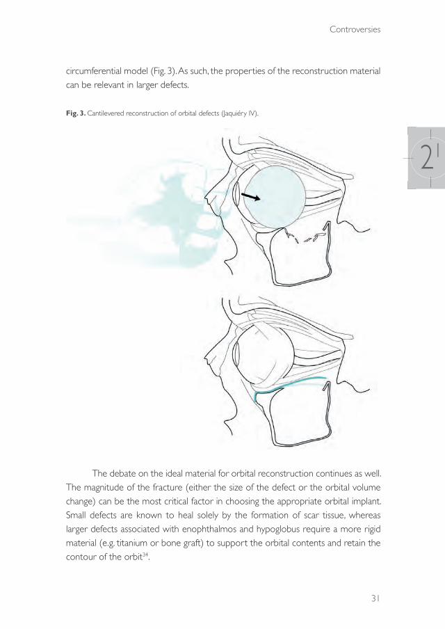
circumferential model (Fig. 3). As such, the properties of the reconstruction material can be relevant in larger defects.
Fig. 3. Cantilevered reconstruction of orbital defects (Jaquiéry IV).
The debate on the ideal material for orbital reconstruction continues as well. The magnitude of the fracture (either the size of the defect or the orbital volume change) can be the most critical factor in choosing the appropriate orbital implant. Small defects are known to heal solely by the formation of scar tissue, whereas larger defects associated with enophthalmos and hypoglobus require a more rigid material (e.g. titanium or bone graft) to support the orbital contents and retain the contour of the orbit34.
39372 Dubois, Leander.indd 31 04-03-16 10:19

Chapter 21
32
Three-dimensional measurements might be the best indicator of the risk of occurrence of clinically disabling enophthalmos. The best non-invasive instrument to quantify orbital fractures is CT with thin-cut axial and coronal recordings, although it often fails to measure the exact level of bony involvement35. Wide exposure of the fractured area seems to be the gold standard for emphasizing the extent of the defect36, but descriptions of the actual defect size and location are rare in most studies. As such, international research would greatly benefit from a clinical classification system for orbital fractures that considers the three-dimensional aspect of the orbit and thus the subsequent volume of the orbital soft tissue displacement.
The decision with regard to the appropriate implant could be made based on the complexity of the fracture. In the literature it is suggested that surgery is indicated in large fractures with involvement of more than 50% of the orbital wall,
or where the surface is larger than 2 cm5. The question remains as to whether these indications can be quantified accurately and whether they are adequately reproducible. Overall, patients with combined fractures of the orbital floor and medial wall, with loss of the medial strut, should be considered at higher risk of developing clinically significant enophthalmos37. In these fractures the three-dimensional changes of the orbit are more significant and the accurate form of an orbital implant becomes more important. Therefore in such cases pre-formed or patient-specific implants may be advantageous.
The indication for surgery in solitary medial wall fractures is even more controversial. No specific prospective studies have been published on this subject. Generally accepted indications are a positive forced duction test or persistent diplopia, with CT evidence of an entrapped muscle37. Although enophthalmos is often mentioned as an indication for surgery as well, the enophthalmos rarely becomes significant (more than 2 mm) in the first 2 weeks after trauma.
An easily usable anatomical classification is essential for clinical communication, and the classification introduced by Jaquiéry gives a good anatomical impression of the defects (Fig. 1). The first studies using this practical tool have been published31,33,38. However, although this model describes the extent of the orbital fracture, it does not address the amount of volumetric change in the orbit. Nonetheless, the latter may very well be essential in the clinical decision-making process. Specifically developed software for the quantification of volumetric changes would be helpful.
In conclusion, currently available studies were analysed in this systematic review and it was found that the data are insufficient to provide a robust basis for guidelines recommending the best reconstruction method(s) for each type of orbital
39372 Dubois, Leander.indd 32 04-03-16 10:19
Controversies
33
21
fracture. Furthermore, in the near future, it will hopefully be possible to identify those defects for which the use of certain biomaterial properties will increase the predictability of the orbital reconstruction. It is the authors’ opinion that uniform standardized tests (e.g., Hertel exophthalmometry and Goldman screens) and validated questionnaires, in combination with a three-dimensional volume-based defect classification, should be used by default in orbital fracture research in the coming decade. Further reproducible trials using a multi-centre setting are needed to address the controversies in orbital fracture management.
acknOwledgeMents
We would like to thank Ingeborg M. Nagel, clinical librarian, for assistance in finding appropriate search terms.
39372 Dubois, Leander.indd 33 04-03-16 10:19

Chapter 21
34
references
1. Warwar RE, Bullock JD, Ballal DR, Ballal RD. Mechanisms of orbital floor fractures: a clinical, experimental, and theoretical study. Ophthal Plast Reconstr Surg 2000: 16: 188–200.
2. Siniković B, Kramer FJ, Swennen G, Lübbers HT, Dempf R. Reconstruction of orbital wall defects with calcium phosphate cement: clinical and histological findings in a sheep model. Int J Oral Maxillofac Surg 2007: 36: 54–61.
3. Putterman AM, Stevens T, Urist MJ. Nonsurgical management of blow-out fractures of the orbital floor. Am J Ophthalmol 1974: 77: 232–239.
4. Hawes MJ, Dortzbach RK. Surgery on orbital floor fractures. Influence of time of repair and fracture size. Ophthalmology 1983: 90: 1066–1070.
5. Burnstine MA. Clinical recommendations for repair of isolated orbital floor fractures: an evidence-based analysis. Ophthalmology 2002: 109: 1207–1210.
6. Burnstine MA. Clinical recommendations for repair of orbital facial fractures. Curr Opin Ophthalmol 2003: 14: 236–240.
7. Bansagi ZC, Meyer DR. Internal orbital fractures in the pediatric age group: characterization and management. Ophthalmology 2000: 107: 829–836.
8. Sires BS, Stanley RB Jr, Levine LM. Oculocardiac reflex caused by orbital floor trapdoor fracture: an indication for urgent repair. Arch Ophthalmol 1998: 116: 955–956.
9. Jordan DR, Allen LH, White J, Harvey J, Pashby R, Esmaeli B. Intervention within days for some orbital floor fractures: the white-eyed blowout. Ophthal Plast Reconstr Surg 1998: 14: 379–390.
10. Egbert JE, May K, Kersten RC, Kulwin DR. Pediatric orbital floor fracture: direct extraocular muscle involvement. Ophthalmology 2000: 107: 1875–1879.
11. Berkowitz RA, Putterman AM, Patel DB. Prolapse of the globe into the maxillary sinus after orbital floor fracture. Am J Ophthalmol 1981: 91: 253–257.
12. Smit TJ, Koornneef L, Zonneveld FW. A total orbital floor fracture with prolapse of the globe into the maxillary sinus manifesting as postenucleation socket syndrome. Am J Ophthalmol 1990: 110: 569–570.
13. Roth A, Desmangles P, Rossillion B. Early treatment of secondary muscle restriction due to orbital blow-out fractures. J Fr Ophtalmol 1999: 22: 645–650.
14. Converse JM, Smith B. Naso-orbital fractures. Trans Am Acad Ophthalmol Otolaryngol 1963: 67: 622–634.
15. Hammer B, Prein J. Correction of post-traumatic orbital deformities: operative techniques and review of 26 patients. J Craniomaxillofac Surg 1995: 23: 81–90.
16. Jaquiéry C, Aeppli C, Cornelius P, Palmowsky A, Kunz C, Hammer B. Reconstruction of orbital wall defects: critical review of 72 patients. Int J Oral Maxillofac Surg 2007: 36: 193–199.
17. Wajih WA, Shaharuddin B, Razak NH. Hospital Universiti Sains Malaysia experience in orbital floor reconstruction: autogenous graft versus Medpor. J Oral Maxillofac Surg 2011: 69: 1740–1744.
18. Becker ST, Terheyden H, Fabel M, Kandzia C, Möller B, Wiltfang J. Comparison of collagen membranes and polydioxanone for reconstruction of the orbital floor after fractures. J Craniofac Surg 2010: 21: 1066–1068.
19. Liberati A, Altman DG, Tetzlaff J, et al. The PRISMA Statement for reporting systematic reviews and meta-analyses of studies that evaluate health care interventions: explanation and elaboration. PLoS Med. 2009;6(7):e1000100.
20. Bayat M, Momen-Heravi F, Khalilzadeh O, Mirhosseni Z, Sadeghi-Tari A. Comparison of conchal cartilage graft with nasal septal cartilage graft for reconstruction of orbital floor blowout fractures. Br J Oral Maxillofac Surg 2010: 48: 617–620.
21. Cai EZ, Koh YP, Hing EC, Low JR, Shen JY, Wong, HC, Sundar G, Lim TC. Computer-assisted navigational surgery improves outcomes in orbital reconstructive surgery. J Craniofac Surg 2012: 23: 1567–1573.
22. Folkestad L, Granström G. A prospective study of orbital fracture sequelae after change of surgical routines. J Oral Maxillofac Surg 2003: 61: 1038–1044.
39372 Dubois, Leander.indd 34 04-03-16 10:19

Controversies
35
21
23. Kontio RK, Laine P, Salo A, Paukku P, Lindqvist C, Suuronen R. Reconstruction of internal orbital wall fracture with iliac crest free bone graft: clinical, computed tomography, and magnetic resonance imaging follow-up study. Plast Reconstruct Surg 2006: 118: 1365–1374.
24. Kontio R, Suuronen R, Salonen O, Paukku P, Konttinen YT, Lindqvist C. Effectiveness of operative treatment of internal orbital wall fracture with polydioxanone implant. Int J Maxillofac Surg 2001: 30: 278-285.
25. Kruschewsky L de S, Novais T, Daltro C, Castelo Branco B, Lessa M, Kruschewsky MB, de Mello-Filho FV. Fractured orbital wall reconstruction with an auricular cartilage graft or absorbable polyacid copolymer. J Craniofac Surg 2011: 22: 1256–1259.
26. Dietz A, Ziegler CM, Dacho A, Althof F, Conradt C, Kolling G, von Boehmer H, Steffen H. Effectiveness of a new perforated 0.15 mm poly-p-dioxanon-foil versus titanium-dynamic mesh in reconstruction of the orbital floor. J Maxillofac Surg 2001: 29: 82–88.
27. Noda M, Noda K, Ideta S, Nakamura Y, Ishida S, Inoue M, Tsubota K. Repair of blowout orbital floor fracture by periosteal suturing. Clin Experiment Ophthalmol 2011: 39: 364–369.
28. Fernandes R, Fattahi T, Steinberg B, Schare H. Endoscopic repair of isolated orbital floor fracture with implant placement. J Oral Maxillofac Surg 2007: 65: 1449–1553.
29. Al-Sukhun J, Lindqvist C. A comparative study of 2 implants used to repair inferior orbital wall bony defects: autogenous bone graft versus bioresorbable poly-l/dl-lactide [P(L/DL)LA 70/30] plate. J Oral Maxillofac Surg 2006: 64: 1038–1048.
30. Scolozzi P, Momjian A, Heuberger J, Andersen E, Broome M, Terzic A, Jaques B. Accuracy and predictability in use of AO three-dimensionally preformed titanium mesh plates for posttraumatic orbital reconstruction: a pilot study. J Craniofac Surg 2009: 20: 1108–1113.
31. Lieger O, Schaller B, Zix J, Kellner F, Iizuka T. Repair of orbital floor fractures using bioresorbable poly-l/dl-lactide plates. Arch Facial Plast Surg 2010: 12: 399–404.
32. Sethi MK, Schoenfeld AJ, Bono CM, Harris MB. The evolution of thoracolumbar injury classification systems. Spine J 2009: 9: 780–788.
33. Van Leeuwen AC, Ong SH, Vissink A, Grijpma DW, Bos RR. Reconstruction of orbital wall defects: recommendations based on a mathematical model. Exp Eye Res 2012: 97: 10–18.
34. Gunarajah DR, Samman N. Biomaterials for repair of orbital floor blowout fractures: a systematic review. J Oral Maxillofac Surg 2013: 71: 550–570.
35. Lelli GJ Jr, Milite J, Maher E. Orbital floor fractures: evaluation, indications, approach, and pearls from an ophthalmologist’s perspective. Facial Plast Surg 2007: 23: 190–199.
36. Iatrou I, Theologie-Lygidakis N, Angelopoulos A. Use of membrane and bone grafts in the reconstruction of orbital fractures. Oral Surg Oral Med Oral Pathol Oral Radiol Endod 2001: 91: 281–286.
37. Choi M, Flores R. Medial orbital wall fractures and the transcaruncular approach. J Craniofac Surg 2012: 23: 696–701.
38. Kunz C, Sigron GR, Jaquiéry C. Functional outcome after non-surgical management of orbital fractures—the bias of decision-making according to size of defect: critical review of 48 patients. Br J Oral Maxillofac Surg 2013: 51: 486–492.
39372 Dubois, Leander.indd 35 04-03-16 10:19
39372 Dubois, Leander.indd 36 04-03-16 10:19

CHAPTER 22
Timing of post-traumatic orbital reconstruction
This chapter is an edited version of the manuscript: Dubois L, Steenen SA, Gooris PJJ, Mourits MP, Becking AG:
Controversies in orbital reconstruction-II. Timing of post-traumatic orbital reconstruction: A systematic review. Int J Oral Maxillofac Surg 2015: 44: 433-440
39372 Dubois, Leander.indd 37 04-03-16 10:19

Chapter 22
38
intrOductiOn
Clinical decision-making in the management of patients with orbital fractures is challenging, and various aspects of orbital fracture management are still debated. Controversies exist regarding the indications for surgery, the timing of surgery, and the best reconstruction material. To date, no uniformly accepted guidelines have been developed for the maximal interval between trauma and reconstructive surgery. However, in many other fields of trauma surgery, an increasing body of evidence is stressing the importance of the optimal timing of surgery1.
Early revision and repair of blow-out fractures has been considered the first-line treatment for optimal surgical outcome2. The major clinical outcome parameters in patients with orbital fractures include functional impairment (vision, extraocular muscle motility disorders, and diplopia), cosmetic disturbance (enophthalmos), and infraorbital hypaesthesia. Ocular motility disturbances due to orbital fractures are often related to contused ocular muscles and post-traumatic oedema. In the 1970s, it was observed that contused ocular muscles usually recover spontaneously within 1 or 2 weeks, thus a conservative approach was suggested in order to avoid surgery-related complications3. The introduction of computed tomography (CT) provided increasingly accurate information on the extent of the fractures and the presence of herniated tissue, and resulted in CT-based treatment protocols in the 1980s and 1990s. The focus of the debate on optimal timing has since then shifted from the indications for early intervention towards the question of which patients are eligible for delayed repair. In general, a distinction needs to be made between immediate (within hours), early (within 2 weeks), and delayed late orbital reconstruction.
There is consensus on the indications for immediate surgery. An emergency situation in orbital trauma exists if a retrobulbar haematoma develops with apical compression of the globe or the optic nerve in combination with impaired vision. These conditions are an indication for immediate surgery within 6 h after presentation4–6. Another indication for urgent surgical intervention is muscle incarceration and possible ischemia in the paediatric patient. New light was shed on the timing issue by Jordan et al.7 in 1998, who found that although children under the age of 16 years presenting with diplopia and vertical gaze restriction (‘white-eyed blow-out fractures’) might show little or no radiological evidence of muscle entrapment, this patient category is vulnerable to the development of eye motility disorders that are highly resistant to surgery. Parbhu et al.8 found that CT evidence for soft tissue entrapment in children is easily missed or underestimated by radiologists because of the trapdoor mechanism.
39372 Dubois, Leander.indd 38 04-03-16 10:19

Controversies
39
22
Minor muscle entrapment in children may rapidly result in muscle fibrosis followed by persistent diplopia, and requires intervention within 2–4 days. In addition, the oculocardiac reflex, due to orbital wall fractures and vagal stimulation in children, causes serious bradycardia with potential life-threatening complications6,9–11.
Indications for early intervention within 2 weeks have also been indicated in the literature, and include enophthalmos larger than 2 mm with significant hypoglobus or diplopia12. Large displaced fracture defects generally require surgery within 2 weeks, since the development of enophthalmos is anticipated. Enophthalmos may be obvious at the time of presentation, but may be masked by oedema or haematoma. However, if surgery is delayed until enophthalmos is apparent, fibrosis may develop between orbital soft tissues, the sinus mucosa, and bone fragments. To prevent fibrosis of the injured orbital tissue, early repair within 2 weeks has been proposed for patients who have clinically unimproved diplopia with radiological evidence of orbital tissue compression13. Delaying the operation further may increase the complexity of the reconstruction14 and introduce the risk of additional complications, such as sinusitis, dacryocystitis, late ptosis, and functional deficits (e.g. enophthalmos, hypoglobus, and diplopia)12.
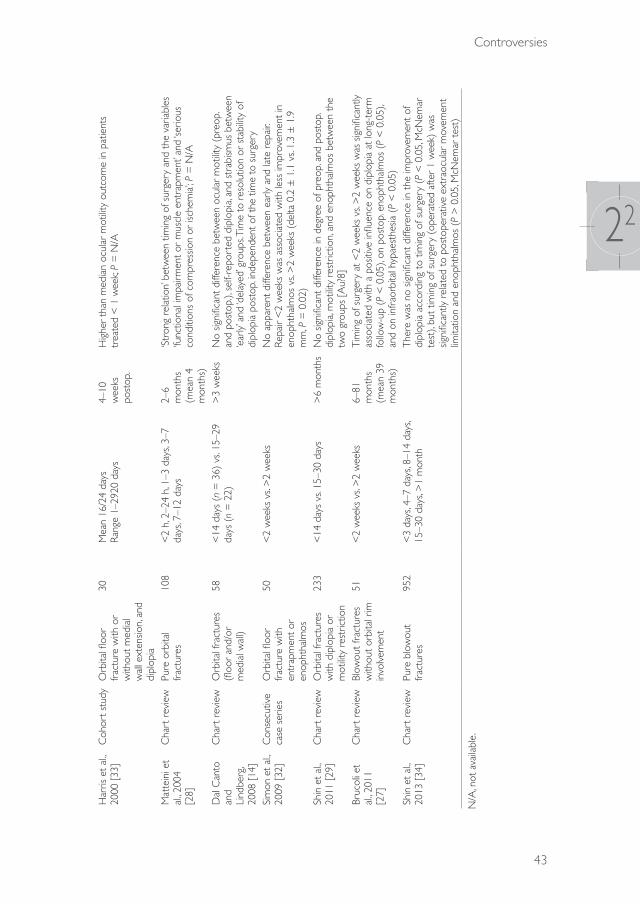
Delayed reconstructions are commonly indicated in patients who have developed aesthetically disturbing enophthalmos or persistent diplopia 2 weeks after trauma. In these patients, the indication for surgical intervention may be uncertain in the early stages after trauma. This uncertainty applies specifically to small orbital defects, e.g. in patients with orbital fractures who have good ocular motility and only slight displacement of the orbital content. In a retrospective study, Dal Canto and Linberg14 found similar complication rates between orbital floor and/or medial wall fracture repairs conducted within 14 days and those performed 15–29 days after trauma. However, the majority of studies10,11,15–18 support early reconstruction because of the better postoperative results and a decreased incidence of diplopia and enophthalmos. These outcomes are thought to result from reduced scarring of soft tissue10,11,15–18. The initial contusion, shearing, and laceration cannot be prevented; however, early reversal of an ongoing tissue crush or severe stretch might limit late fibrosis, especially in cases of fractures with disproportionate soft tissue displacement11.
If an orbital wall defect needs reconstruction, several decisions need to be made on the timing of surgery. The aim of the present study was to systematically review all the available controlled clinical trials on post-traumatic orbital reconstruction with a focus on the timing, or delay of surgery.
39372 Dubois, Leander.indd 39 04-03-16 10:19

Chapter 22
40
MethOds
A systematic literature search in PubMed (updated 14 September 2013; all indexed years) with multiple search terms was performed, combining the subjects ‘orbital fracture’, ‘timing’, and ‘delay’. The search excluded case series with 10 or fewer subjects, and the language was restricted to English, German, and Dutch. All prospective and retrospective human clinical studies reporting comparative data regarding the interval between the injury and the reconstructive orbital surgery and also the outcome of the orbital fracture treatment met our entry criteria; these studies could include either adults or children. During the primary review process (performed in accordance with the PRISMA criteria (Preferred Reporting Items for Systematic Reviews and Meta-Analyses) for systematic reviews19), two authors (SS and LD) assessed the relevance of the retrieved articles based on the abstracts. In a secondary review, full articles were retrieved, and relevant articles were included. Any disagreements were resolved through discussions with a third person (PG). Fig. 1 shows a flow diagram of the inclusion process.
The PubMed search terms (all indexed years) were as follows: ((((“Orbital Fractures”[Mesh] OR orbital fracture*[tiab] OR orbit fracture*[tiab] OR orbital trauma*[tiab] OR orbit trauma*[tiab] OR orbital injur*[tiab] OR orbit injur*[tiab] OR orbital wall fracture*[tiab] OR orbital wall injur*[tiab] OR orbital wall trauma*[tiab] OR orbital floor fracture*[tiab] OR orbital floor injur*[tiab] OR orbital floor trauma*[tiab] OR blow-out fracture*[tiab] OR blowout fracture*[tiab] OR supraorbital fracture*[tiab] OR trapdoor fracture*[tiab] OR malar fracture*[tiab] OR tripod fracture*[tiab] OR orbitozygomatic fracture*[tiab] OR orbito-zygomatic fracture*[tiab] OR zygomatico-orbital fracture*[tiab] OR tripartite fracture*[tiab] OR (le fort[tiab] AND fracture*[tiab]) OR (lefort[tiab] AND fracture*[tiab]))) AND (“Time”[Mesh] OR time[tiab] OR timing[tiab] OR delay*[tiab] OR moment[tiab] OR wait*[tiab] OR early[tiab] OR late[tiab] OR week*[tiab] OR day[tiab] OR days[tiab])) NOT (case reports[pt] NOT (cases[tiab] OR series[tiab] OR group[tiab] OR patients[tiab] OR review[tiab] OR retrospective[tiab]))) AND (English[la] OR Dutch[la] OR German[la]).
39372 Dubois, Leander.indd 40 04-03-16 10:19

Controversies
41
22
Fig. 1. Flow diagram of the present review, performed in accordance with the PRISMA criteria
results
In the systematic search, a total of 17 studies including 1579 patients with orbital injuries were identifi ed (Tables 1 and 2).
39372 Dubois, Leander.indd 41 04-03-16 10:19
Chapter 22
42
Tabl
e 1.
Ove
rvie
w o
f pro
spec
tive
stud
ies
on t
he t
imin
g of
sur
gica
l orb
ital f
ract
ure
repa
ir, 20
06–2
010.
Stud
y [R
ef.]
Des
ign
Frac
ture
typ
eSu
rgic
al
tech
niqu
eN
umbe
r of
pa
tient
sIn
terv
al fr
om
inju
ry t
o su
rger
y (d
elay
)
Follo
w-u
pRe
sults
Baya
t et
al,
2010
[20
]Ra
ndom
ized
cont
rolle
d cl
inic
al t
rial
Blow
out
frac
ture
sN
asal
sep
tal
cart
ilage
(11
) vs
. co
ncha
l car
tilag
e (1
1)
22<
4 w
eeks
: n =
8
>4
wee
ks: n
= 1
33–
6 m
onth
sA
t ba
selin
e, d
iffer
ence
s in
the
mea
n va
lues
of t
he
enop
htha
lmos
bet
wee
n pa
tient
s tr
eate
d w
ithin
or
afte
r 4
wee
ks o
f inj
ury
wer
e no
n-sig
nific
ant
(mea
n (S
D),
4.8
(0.8
9) v
s. 5.
1 (0
.8)
mm
, res
pect
ivel
y; P
= N
S). H
owev
er,
the
mea
n co
rrec
tion
of t
he e
noph
thal
mos
(an
d re
sidua
l eno
phth
alm
os)
was
sig
nific
antly
hig
her
(and
lo
wer
) at
eac
h fo
llow
-up
visit
in p
atie
nts
who
wer
e tr
eate
d w
ithin
4 w
eeks
of i
njur
y (P
= N
/A)
Kont
io e
t al
., 20
06 [
21]
Coh
ort
stud
yIso
late
d flo
or
(11)
and
floo
r w
ith a
ssoc
iate
d fa
cial
frac
ture
(1
3)
Aut
ogen
ous
iliac
cort
ical
gra
ft24
7 da
ys
(ran
ge 0
–26)
5–13
m
onth
sTi
min
g of
the
ope
ratio
n di
d no
t af
fect
the
occ
urre
nce
of d
iplo
pia
(P =
N/A
)
NS,
not
signi
fican
t; SD
, sta
ndar
d de
viat
ion;
N/A
, not
ava
ilabl
e.
Tabl
e 2.
Ove
rvie
w o
f ret
rosp
ectiv
e st
udie
s on
the
tim
ing
of s
urgi
cal o
rbita
l fra
ctur
e re
pair
in a
dults
, 198
3–20
11
Stud
y [R
ef.]
Des
ign
Frac
ture
typ
eN
umbe
r of
pa
tient
s
Inte
rval
from
inju
ry t
o su
rger
y (d
elay
)Fo
llow
-up
Resu
lts
Haw
es a
nd
Dor
tzba
ch,
1983
[31
]
Con
secu
tive
case
ser
ies
Orb
ital fl
oor
frac
ture
s (e
ither
w
ith d
iplo
pia
or
enop
htha
lmos
)
51<
2 m
onth
s (n
= 4
3) v
s. >
2 m
onth
s (n
= 8
)>
6 w
eeks
‘Ear
ly’ v
s. ‘la
te’ r
epai
rEn
opht
halm
os p
osto
pera
tive:
7%
vs.
50%
(P
< 0
.002
)M
otilit
y ‘sa
tisfa
ctor
ily’ c
orre
cted
: 88%
vs.
40%
(P
< 0
.02)
Verh
oeff
et a
l., 19
98
[30]
Cha
rt r
evie
wO
rbita
l tra
uma
with
sub
sequ
ent
mot
ility
diso
rder
s ne
edin
g re
pair
28<
2 w
eeks
vs.
>2
wee
ks;
<2
mon
ths
vs. >
2 m
onth
s>
6 m
onth
sH
ighe
r co
mpl
ete
reco
very
rat
e in
ear
lier
repa
ir (7
3% <
2 w
eeks
vs.
40%
<2
mon
ths
vs. 2
5% >
6 m
onth
s); P
= N
/A
39372 Dubois, Leander.indd 42 04-03-16 10:19
Controversies
43
22
Har
ris e
t al
., 20
00 [
33]
Coh
ort s
tudy
Orb
ital fl
oor
frac
ture
with
or
with
out
med
ial
wal
l ext
ensio
n, a
nd
dipl
opia
30M
ean
16/2
4 da
ys
Rang
e 1–
2920
day
s4–
10
wee
ks
post
op.
Hig
her
than
med
ian
ocul
ar m
otilit
y ou
tcom
e in
pat
ient
s tr
eate
d <
1 w
eek;
P =
N/A
Mat
tein
i et
al., 2
004
[28]
Cha
rt r
evie
wPu
re o
rbita
l fr
actu
res
108
<2
h, 2
–24
h, 1
–3 d
ays,
3–7
days
, 7–1
2 da
ys2–
6 m
onth
s (m
ean
4 m
onth
s)
‘Str
ong
rela
tion’
bet
wee
n tim
ing
of s
urge
ry a
nd t
he v
aria
bles
‘fu
nctio
nal i
mpa
irmen
t or
mus
cle
entr
apm
ent’
and
‘serio
us
cond
ition
s of
com
pres
sion
or is
chem
ia’; P
= N
/A
Dal
Can
to
and
Lind
berg
, 20
08 [
14]
Cha
rt r
evie
wO
rbita
l fra
ctur
es
(floo
r an
d/or
m
edia
l wal
l)
58<
14 d
ays
(n =
36)
vs.
15–2
9 da
ys (
n =
22)
>3
wee
ksN
o sig
nific
ant
diffe
renc
e be
twee
n oc
ular
mot
ility
(pre
op.
and
post
op.),
sel
f-rep
orte
d di
plop
ia, a
nd s
trab
ismus
bet
wee
n ‘e
arly
’ and
‘del
ayed
’ gro
ups.
Tim
e to
res
olut
ion
or s
tabi
lity
of
dipl
opia
pos
top.
inde
pend
ent
of t
he t
ime
to s
urge
rySi
mon
et
al.,
2009
[32
]C
onse
cutiv
e ca
se s
erie
sO
rbita
l floo
r fr
actu
re w
ith
entr
apm
ent
or
enop
htha
lmos
50<
2 w
eeks
vs.
>2
wee
ksN
o ap
pare
nt d
iffer
ence
bet
wee
n ea
rly a
nd la
te r
epai
r. Re
pair
<2
wee
ks w
as a
ssoc
iate
d w
ith le
ss im
prov
emen
t in
en
opht
halm
os v
s. >
2 w
eeks
(de
lta 0
.2 ±
1.1
vs.
1.3
± 1
.9
mm
, P =
0.0
2)Sh
in e
t al
., 20
11 [
29]
Cha
rt r
evie
wO
rbita
l fra
ctur
es
with
dip
lopi
a or
m
otilit
y re
stric
tion
233
<14
day
s vs
. 15–
30 d
ays
>6
mon
ths
No
signi
fican
t di
ffere
nce
in d
egre
e of
pre
op. a
nd p
osto
p.
dipl
opia
, mot
ility
rest
rictio
n, a
nd e
noph
thal
mos
bet
wee
n th
e tw
o gr
oups
[A
u?8]
Bruc
oli e
t al
., 201
1 [2
7]
Cha
rt r
evie
wBl
owou
t fr
actu
res
with
out
orbi
tal r
im
invo
lvem
ent
51<
2 w
eeks
vs.
>2
wee
ks6–
81
mon
ths
(mea
n 39
m
onth
s)
Tim
ing
of s
urge
ry a
t <
2 w
eeks
vs.
>2
wee
ks w
as s
igni
fican
tly
asso
ciat
ed w
ith a
pos
itive
influ
ence
on
dipl
opia
at
long
-ter
m
follo
w-u
p (P
< 0
.05)
, on
post
op. e
noph
thal
mos
(P
< 0
.05)
, an
d on
infr
aorb
ital h
ypae
sthe
sia (
P <
0.0
5)Sh
in e
t al
., 20
13 [
34]
Cha
rt r
evie
wPu
re b
low
out
frac
ture
s95
2 <
3 da
ys, 4
–7 d
ays,
8–14
day
s, 15
–30
days
, >1
mon
thTh
ere
was
no
signi
fican
t di
ffere
nce
in t
he im
prov
emen
t of
di
plop
ia a
ccor
ding
to
timin
g of
sur
gery
(P
< 0
.05,
McN
emar
te
st),
but
timin
g of
sur
gery
(op
erat
ed a
fter
1 w
eek)
was
sig
nific
antly
rel
ated
to
post
oper
ativ
e ex
trao
cula
r m
ovem
ent
limita
tion
and
enop
htha
lmos
(P
> 0
.05,
McN
emar
tes
t)
N/A
, not
ava
ilabl
e.
39372 Dubois, Leander.indd 43 04-03-16 10:19
Chapter 22
44
Prospective studiesSeveral prospective studies on orbital fracture surgery specified the timing of the reconstruction. The timeframe reported typically ranged from immediate repair to repair within 1 month after the injury20–25, with the exception of one study in which the maximum interval ranged up to 3 months after trauma26. Nonetheless, only two of these studies analysed the actual effect of timing as a variable in the clinical outcome measures (Table 1)20,21.
One randomized controlled trial by Bayat et al.20 compared the effects of nasal septal cartilage (n = 11) with conchal cartilage (n = 11) for orbital blowout fracture reconstruction, and found that timing the reconstruction to <4 weeks after the injury had a significant positive effect on postoperative enophthalmos. However in this study, the timing of the operation was not randomized over the groups, and it was not specified why the subjects were treated earlier or to which groups they were allocated.
In addition, a cohort study by Kontio et al.21 followed 24 subjects with orbital floor fractures (of whom 13 had associated facial fractures) for a mean 234 days (range 146–406 days), and found no correlation between the timing of the operation (mean 7 days, range 0–26 days) and the outcome of postoperative diplopia.
Collectively, the results suggest that the prospective studies have not provided evidence on whether to perform early, delayed, or late orbital reconstruction.
Retrospective studiesThere are numerous retrospective studies in the literature providing descriptive data on the timing of orbital reconstruction. However, only 15 studies were found that reported comparative analyses on the effect of surgical timing on various clinical outcome measures (Tables 2 and 3). Nine of these studies included only adult patients14,27–34, four studies, only paediatric patients7,35–37, and two included both adults and children38,39.
With regard to adult orbital fractures, four studies found a statistically significant positive effect of the earlier timing of surgery on clinical outcome measures (enophthalmos and ocular motility)27,31,33,34, whereas five studies were inconclusive (Table 2)14,28,29, 30,32.”.
With regard to paediatric orbital fractures, one study with paediatric patients found a statistically significant correlation between surgery performed within 3 weeks and diplopia at long-term follow-up36, while five studies were inconclusive (Table 3)7,35,37–39.
39372 Dubois, Leander.indd 44 04-03-16 10:19

Controversies
45
22
Tabl
e 3.
Ove
rvie
w o
f ret
rosp
ectiv
e st
udie
s on
the
tim
ing
of s
urgi
cal o
rbita
l fra
ctur
e re
pair
in c
hild
ren,
199
8–20
11.
Stud
y [R
ef.]
Des
ign
Frac
ture
typ
eA
ge,
year
sN
umbe
r of
pat
ient
sIn
terv
al fr
om
inju
ry t
o su
rger
y (d
elay
)
Follo
w-u
pRe
sults
Jord
an e
t al
., 199
8 [7
]C
hart
re
view
Post
-tra
umat
ic
enop
htha
lmos
or
dip
lopi
a w
ith
mot
ility
diso
rder
; ‘w
hite
-eye
d bl
owou
t’
4–18
20Ra
nge
48 h
–40
days
<
48 h
: n =
5
>48
h t
o <
4 da
ys: n
= 1
>
14 t
o <
40 d
ays:
n =
14
4 w
eeks
to
1 ye
arIn
pat
ient
s w
ho h
ad s
urge
ry w
ithin
4 d
ays
(n =
5),
sym
ptom
s re
solv
ed b
etw
een
3 an
d 6
wee
ks p
osto
p.
Patie
nts
who
had
sur
gery
at
2–3
wee
ks t
ende
d to
sh
ow s
low
er s
ympt
om r
esol
utio
n (o
ver
mon
ths)
; 3
patie
nts
had
perm
anen
t re
stric
tion
(P =
N/A
)
Ger
bino
et
al.,
2010
[3
5]
Cha
rt
revi
ewTr
apdo
or
frac
ture
s6–
1624
Rang
e <
24 h
–192
h
<24
h: n
= 1
2 (‘u
rgen
t’)
>24
to
<96
h: n
= 8
(‘e
arly
’) >
96 h
: n =
4 (
‘del
ayed
’)
Ave
rage
36
mon
ths
A c
orre
latio
n w
as fo
und
betw
een
timin
g (<
24 h
vs
. >24
to
<96
h v
s. >
96 h
) w
ith r
egar
d to
res
idua
l di
plop
ia (
8.3%
vs.
37.5
% v
s. 10
0%)
at fo
llow
-up
(P
= N
/A)
Wan
g et
al.,
2010
[37
]C
hart
re
view
Blow
-out
frac
ture
5–18
(m
ean
12.7
)
410–
2 da
ys: n
= 4
(‘im
med
iate
’)3–
14 d
ays:
n =
18
(‘ear
ly’)
15–3
0 da
ys: n
= 1
1 (‘d
elay
ed’)
>30
day
s: n
= 8
(‘la
te’)
Mea
n 6.
5 m
onth
s (r
ange
0.
3–59
)
Hig
her
mea
n ch
ange
s in
sup
radu
ctio
n lim
itatio
n w
hen
oper
ated
afte
r 3–
14 d
ays
vs. <
2 da
ys (
P =
0.4
7). S
urge
ry a
t <
1 m
onth
: 60%
com
plet
e re
solu
tion
of p
reop
. mot
ility
rest
rictio
n an
d 51
.6%
co
mpl
ete
reso
lutio
n of
dip
lopi
a at
follo
w-u
p, v
s. 0%
im
prov
emen
t of
dip
lopi
a an
d m
otilit
y w
hen
oper
ated
at
>1
mon
th (
P =
N/A
)Et
huna
ndan
an
d Ev
ans,
2011
[39
]
Cas
e se
ries
Blow
out
frac
ture
w
ith p
ainf
ul g
aze
rest
rictio
n
4–53
(m
ean
19.6
)
10Ra
nge
0–41
day
s (m
ean
12.3
day
s)M
ean
5.1
mon
ths
(ran
ge
1–12
)
No
dipl
opia
at
follo
w-u
p in
pat
ient
s w
ho h
ad s
urge
ry
with
in 7
day
s. O
ne p
atie
nt t
reat
ed a
t 20
day
s ha
d tr
oubl
esom
e di
plop
ia t
hat
requ
ired
extr
aocu
lar
mus
cle
surg
ery.
Non
e of
the
oth
er p
atie
nts,
incl
udin
g on
e tr
eate
d 41
day
s af
ter
inju
ry, h
ad a
ny r
elev
ant
resid
ual
dipl
opia
(P
= N
/A)
Am
rith
et
al., 2
010
[38]
Con
secu
tive
case
ser
ies
Blow
out
frac
ture
7–76
(m
edia
n 27
)
63
(13
child
ren)
<1
wee
k, >
1 w
eek
>6
mon
ths
(53%
) <
6 m
onth
s (4
7%)
Chi
ldre
n ha
d ea
rlier
sur
gery
tha
n ad
ults
(P
< 0
.001
) an
d te
nded
to
have
bet
ter
mot
ility
outc
omes
tha
n ad
ults
(ho
wev
er, P
= 0
.684
). Su
rger
y at
<1
wee
k sh
owed
a t
rend
tow
ards
bet
ter
mot
ility
outc
omes
(P
= 0
.231
)N
owin
ski
et a
l., 20
10
[36]
Cha
rt
revi
ewC
ompl
ex o
rbita
l fr
actu
res
in
com
bina
tion
with
tr
aum
atic
bra
in
inju
ry
5–15
(m
ean
9.4)
14<
3 w
eek:
n =
11
(‘ear
ly’)
>3
wee
k: n
= 3
(‘p
ostp
oned
’)4.
7 ye
ars
(ran
ge
1.2–
13.1
)
Cor
rela
tion
betw
een
surg
ery
at >
3 w
eeks
and
di
plop
ia a
t lo
ng-t
erm
follo
w-u
p (P
= 0
.04,
Fish
er’s
exac
t te
st)
N/A
, not
ava
ilabl
e.
39372 Dubois, Leander.indd 45 04-03-16 10:19

Chapter 22
46
In summary, two retrospective studies found some advantageous effects for surgery performed at <2 weeks for adults, although six studies found no significant differences, and one of six studies in paediatric patients provided evidence for a correlation between earlier repair and the occurrence of diplopia and extraocular motility disorders.
discussiOn
This review identified two prospective and 15 retrospective trials concerning the effects of surgical timing on post-traumatic orbital reconstruction outcomes. Although most authors agree on the indications for immediate intervention, no randomized controlled trials have evaluated the effects of surgical timing as an independent variable on clinical outcome measures. A strong limitation to the majority of studies is that the reasons for the different time intervals between trauma and reconstruction chosen by the clinicians and institutions are rarely specified. It has been proposed that early surgical intervention may improve the ultimate outcome, but identifying patients at risk of late complications remains challenging40. Although there is strong consensus on the indications for immediate repair, current available data are insufficient to provide a solid base for guidelines on optimal timing of orbital fracture reduction.
Quantification and analysis of orbital trauma is highly complex due to the heterogeneous nature of the injuries. First, orbital volume is dependent on soft tissue components, which tend to change over time (e.g. post-traumatic oedema, incarceration of peri-orbital tissue, late fibrosis, and late atrophy). Second, the size and location of the bony defect and volumetric changes can be critical factors with regard to the clinical outcome41. Differences in results between studies must thus be interpreted with caution.
Orbital wall fracture reconstruction itself may produce dissatisfactory results27, such as persistent diplopia or enophthalmos. For the development of evidence-based treatment guidelines, it is necessary to review and investigate all variables that influence these outcomes41. Some logistical factors such as patient delay, doctor’s delay, and the availability of operating rooms may influence the timing of surgery. Recent studies have shown that technological advancements such as preoperative planning, rapid prototyping, customized implants, and intraoperative navigation may influence the predictability of the orbital reconstruction42–45. However, additional
39372 Dubois, Leander.indd 46 04-03-16 10:19
Controversies
47
22
unwanted effects of new technologies can include the need for extra time and manpower for planning, preparing, and performing surgery. It has been reported that the surgeon’s experience may also be an important factor in the outcome of complex reconstructions46,47. After 1–2 weeks, most swelling has disappeared, which allows a more cosmetic assessment. Extra time may therefore prove to be a co-variable positively influencing the outcome of reconstruction.
A minimally displaced orbital fracture is generally referred to as a ‘small fracture’. However, a significant transient displacement of bone fragments at the time of injury may remain unnoticed after the entrapped soft tissues have snapped back into position. In these cases, motility rather than volume is the primary concern, and surgery is usually advised only if there is clinically significant diplopia that does not resolve within 2 weeks, when most of the acute swelling has disappeared. Putterman et al.3 were the first to evaluate this conservative approach. Some years later, the Amsterdam-Korneef group found that diplopia in blow-out fractures due to oedema, haematoma, or oculomotor nerve palsy (n = 17) recovered spontaneously within 1 year after injury in all patients48 . Since it has been shown that entrapment is easily missed or underestimated in CT scans of younger patients (<16 years of age) who present with diplopia and/or motility disturbances after trauma, the conservative approach applied to children may lead to eye motility disorders highly resistant to surgery7,8. These patients are likely to benefit from immediate or early intervention.
Entrapment of peri-orbital tissue may lead to early fibrosis followed by persistent diplopia8. Nowinski et al.36 have shown an association between early reconstruction and the prevention of fibrosis. However, five other studies on paediatric patients found no differences between groups7,35,37–39. Everhard-Halm et al.48 demonstrated a complex network of fibrous septa that functionally unite the sheath of the inferior rectus muscle, the fibro-fatty tissues, and the periosteum of the orbital floor. In orbital fractures, motility may be limited by displacement of this entire complex, or by entrapment of any of its components. It is unclear which tissue types (peri-orbital content such as fat, septa, periosteum, or muscle) are responsible for late motility disorders, and it should be specified whether the inferior rectus muscle or the inferior oblique muscle contributes most to motility limitations.
Enophthalmos related to shredding of the fat of the peri-orbit due to trauma or surgery is difficult to predict. Overcorrection in reconstructive surgery is sometimes recommended, but it is unknown to what extent. A core benefit of early intervention is the reduction of fat atrophy. A recent consensus is that early reconstruction results in less enophthalmos because of minimal soft tissue
39372 Dubois, Leander.indd 47 04-03-16 10:19

Chapter 22
48
scarring10,11,15–18. The initial haematoma with contusion, shearing, and laceration of the orbital content cannot be prevented, but early reconstruction may limit damage to the fatty tissue11. This theory states that late reconstruction leads to novel haematoma formation and may therefore subsequently cause even more fatty tissue atrophy. However, supporting evidence remains limited.
It should be noted that in rare cases, surgery may also be delayed because of contraindications such as the patient’s general condition not allowing surgery, an orbital fracture near the only seeing eye, or severe ocular injury (e.g. retinal detachment, ruptured globe, hyphema, or traumatic optic nerve lesions).
Orbital reconstruction is challenging because of the high level of unpredictability. A perfect anatomical reconstruction does not guarantee a perfect aesthetic and functional outcome, because soft tissue involvement poses difficulties in predicting the long-term effect on function and aesthetics41. Different aspects of timing are believed to influence surgical outcome both positively and negatively. Based on this systematic review, it is our opinion that the Burnstine criteria must be critically revisited (Table 4).
Table 4. Criteria for orbital fracture treatment.
TimeframeImmediate Early DelayedWithin 24 h 1–14 days >14 days
Indications • Diplopia with CT evidence of an entrapped muscle or peri-or-bital tissue associated with a non-resolving oculocardiac reflex: bradycardia, heart block, nausea, vomiting, or syncope
• ‘White-eyed blow-out fracture’, young patient (<18 years), his-tory of peri-ocular trauma, little ecchymosis or oedema (white eye), marked extraocular motility vertical restriction, and CT exam-ination revealing an orbital floor fracture with entrapped muscle or peri-muscular soft tissue
• Significant globe displacement with vision threatening emergency
• Early enophthalmos/hypoglobus causing facial asymmetry
• Symptomatic diplopia with positive forced duction, evidence of an entrapped muscle or peri-muscular soft tissue on CT examination
• Large floor fracture (>50% surface displaced) causing latent enophthal-mos
• Symptomatic diplo-pia without proven entrapment on CT examination, nega-tive forced duction, and minimal clinical improvement over time
• Late-onset enoph-thalmos/ hypoglobus
CT, computed tomography.
In conclusion, this systematic review has analysed currently available data and it is concluded that insufficient data are available to provide a robust basis for guidelines on the best timing of orbital reconstruction. The evidence for early post-traumatic orbital reconstruction is limited to expert opinions and retrospective
39372 Dubois, Leander.indd 48 04-03-16 10:19

Controversies
49
22
analyses. Several confounders, such as local standards, available operating room time, legal matters, and insurance, may influence the clinician’s decision with regard to the timing of reconstruction. Prospective studies are required, and should evaluate the extent of bony orbital trauma, whether soft tissue entrapment is present, the origin of the tissue involved, and how much time has elapsed between the trauma and diagnosis. Age has been shown to play an important role in the timing of surgical intervention. Adequate follow-up to record potential postoperative complications is essential. Future research must strive to establish a relationship between the extent of the trauma, the time between trauma and intervention, and age.
acknOwledgeMents
We would like to thank Ingeborg M. Nagel, clinical librarian, for assistance in identifying appropriate search terms.
39372 Dubois, Leander.indd 49 04-03-16 10:19
Chapter 22
50
references
1. Vallier HA, Wang X, Moore TA, Wilber JH, Como JJ. Timing of orthopaedic surgery in multiple trauma patients: development of a protocol for early appropriate care. J Orthop Trauma 2013: 27: 543–551.
2. Smith B, Regan WF Jr. Blow-out fracture of the orbit; mechanism and correction of internal orbital fracture. Am J Ophthalmol 1957: 44: 733–739.
3. Putterman AM, Stevens T, Urist MJ. Nonsurgical management of blow-out fractures of the orbital floor. Am J Ophthalmol 1974: 77: 232–239.
4. Girotto JA, Gamble WB, Robertson B, Redett R, Muehlberger T, Mayer M, Zinreich J, Iliff N, Miller N, Manson PN. Blindness after reduction of facial fractures. Plast Reconstruct Surg 1998: 102: 1821–1834.
5. Gerbino G, Ramieri GA, Nasi A. Diagnosis and treatment of retrobulbar haematomas following blunt orbital trauma: a description of eight cases. Int J Oral Maxillofac Surg 2005: 34: 127–131.
6. Burnstine MA. Clinical recommendations for repair of isolated orbital floor fractures: an evidence-based analysis. Ophthalmology 2002: 109: 1207–1210.
7. Jordan DR, Allen LH, White J, Harvey J, Pashby R, Esmaeli B. Intervention within days for some orbital floor fractures: the white-eyed blowout. Ophthal Plast Reconstr Surg 1998: 14: 379–390.
8. Parbhu KC, Galler KE, Li C, Mawn LA. Underestimation of soft tissue entrapment by computed tomography in orbital floor fractures in the pediatric population. Ophthalmology 2008: 115: 1620–1625.
9. Yoon KC, Seo MS, Park YG. Orbital trapdoor fracture in children. J Korean Med Sci 2003: 18: 881–885.
10. Egbert JE, May K, Kersten RC, Kulwin DR. Pediatric orbital floor fracture: direct extraocular muscle involvement. Ophthalmology 2000: 107: 1875–1879.
11. Harris GJ. Orbital blow-out fractures: surgical timing and technique. Eye (Lond) 2006: 20: 1207–1212.
12. Burnstine MA. Clinical recommendations for repair of orbital facial fractures. Curr Opin Ophthalmol 2003: 14: 236–240.
13. Roth A, Desmangles P, Rossillion B. Early treatment of secondary muscle restriction due to orbital blow-out fractures. J Fr Ophtalmol 1999: 22: 645–650.
14. Dal Canto AJ, Linberg JV. Comparison of orbital fracture repair performed within 14 days versus 15 to 29 days after trauma. Ophthal Plast Reconstruct Surg 2008: 24: 437–443.
15. Nam SB, Bae YC, Moon JS, Kang YS. Analysis of the postoperative outcome in 405 cases of orbital fracture using 2 synthetic orbital implants. Ann Plast Surg 2006: 56: 263–267.
16. Bansagi ZC, Meyer DR. Internal orbital fractures in the pediatric age group: characterization and management. Ophthalmology 2000: 107: 829–836.
17. Hoşal BM, Beatty RL. Diplopia and enophthalmos after surgical repair of blowout fracture. Orbit 2002: 21: 27–33.
18. Gosau M, Schöneich M, Draenert FG, Ettl T, Driemel O, Reichert TE. Retrospective analysis of orbital floor fractures—complications, outcome, and review of literature. Clin Oral Investig 2011: 15: 305–313.
19. Moher D, Liberati A, Tetzlaff J, Altman DG; PRISMA Group (2009). Preferred reporting items for systematic reviews and meta-analyses: the PRISMA statement. PLoS Med 2009: 6: e1000097.
20. Bayat M, Momen-Heravi F, Khalilzadeh O, Mirhosseni Z, Sadeghi-Tari A. Comparison of conchal cartilage graft with nasal septal cartilage graft for reconstruction of orbital floor blowout fractures. Br J Oral Maxillofac Surg 2010: 48: 617–620.
21. Kontio RK, Laine P, Salo A, Paukku P, Lindqvist C, Suuronen R. Reconstruction of internal orbital wall fracture with iliac crest free bone graft: clinical, computed tomography, and magnetic resonance imaging follow-up study. Plast Reconstruct Surg 2006: 118: 1365–1374.
22. Al-Sukhun J, Törnwall J, Lindqvist C, Kontio R. Bioresorbable poly-l/dl-lactide (P[L/DL]LA 70/30) plates are reliable for repairing large inferior orbital wall bony defects: a pilot study. J Oral Maxillofac Surg 2006: 64: 47–55.
23. Lieger O, Schaller B, Kellner F, Messmer-Schai B, Iizuka T. Low-profile titanium mesh in the use of orbital reconstruction: a pilot study. Laryngoscope 2012: 122: 982–991.
24. Folkestad L, Granström G. A prospective study of orbital fracture sequelae after change of surgical routines. J Oral Maxillofac Surg 2003: 61: 1038–1044.
39372 Dubois, Leander.indd 50 04-03-16 10:19
Controversies
51
22
25. Fernandes R, Fattahi T, Steinberg B, Schare H. Endoscopic repair of isolated orbital floor fracture with implant placement. J Oral Maxillofac Surg 2007: 65: 1449–1453.
26. Noda M, Noda K, Ideta S, Nakamura Y, Ishida S, Inoue M, Tsubota K. Repair of blowout orbital floor fracture by periosteal suturing. Clin Experiment Ophthalmol 2011: 39: 364–369.
27. Brucoli M, Arcuri F, Cavenaghi R, Benech A. Analysis of complications after surgical repair of orbital fractures. J Craniofac Surg 2011: 22: 1387–1390.
28. Matteini C, Renzi G, Becelli R, Belli E, Iannetti G. Surgical timing in orbital fracture treatment: experience with 108 consecutive cases. J Craniofac Surg 2004: 15: 145–150.
29. Shin KH, Baek SH, Chi M. Comparison of the outcomes of non-trapdoor-type blowout fracture repair according to the time of surgery. J Craniofac Surg 2011: 22: 1426–1429.
30. Verhoeff K, Grootendorst R, Wijngaarde R, de Man K. Surgical repair of orbital fractures: how soon after trauma? Strabismus 1998: 6: 77–80.
31. Hawes MJ, Dortzbach RK. Surgery on orbital floor fractures. Influence of time of repair and fracture size. Ophthalmology 1983: 90: 1066–1070.
32. Simon GJ, Syed HM, McCann JD, Goldberg RA. Early versus late repair of orbital blowout fractures. Ophthalmic Surg Lasers Imaging 2009: 40: 141–148.
33. Harris GJ, Garcia GH, Logani SC, Murphy ML. Correlation of preoperative computed tomography and postoperative ocular motility in orbital blowout fractures. Ophthalmic Plast Reconstruct Surg 2000: 16: 179–187.
34. Shin JW, Lim JS, Yoo G, Byeon JH. An analysis of pure blowout fractures and associated ocular symptoms. J Craniofac Surg 2013: 24: 703–707.
35. Gerbino G, Roccia F, Bianchi FA, Zavattero E. Surgical management of orbital trapdoor fracture in a pediatric population. J Oral Maxillofac Surg 2010: 68: 1310–1316.
36. Nowinski D, Di Rocco F, Roujeau T, Meyer P, Renier D, Arnaud E. Complex pediatric orbital fractures combined with traumatic brain injury: treatment and follow-up. J Craniofac Surg 2010: 21: 1054–1059.
37. Wang NC, Ma L, Wu SY, Yang FR, Tsai YJ. Orbital blow-out fractures in children: characterization and surgical outcome. Chang Gung Med J 2010: 33: 313–320.
38. Amrith S, Almousa R, Wong WL, Sundar G. Blowout fractures: surgical outcome in relation to age, time of intervention, and other preoperative risk factors. Craniomaxillofac Trauma Reconstr 2010: 3: 131–136.
39. Ethunandan M, Evans BT. Linear trapdoor or “white-eye” blowout fracture of the orbit: not restricted to children. Br J Oral Maxillofac Surg 2011: 49: 142–147.
40. Palmieri CF, Ghali GE. Late correction of orbital deformities. Oral Maxillofac Surg Clin North Am 2012: 24: 649–663.
41. Dubois L, Steenen SA, Gooris PJ, Mourits MP, Becking AG. Controversies in orbital reconstruction—I. Defect-driven orbital reconstruction: a systematic review, Int J Oral Maxillofac Surg 44, 2015, 308–315.
42. Schön R, Metzger MC, Zizelmann C, Weyer N, Schmelzeisen R. Individually preformed titanium mesh implants for a true-to-original repair of orbital fractures. Int J Oral Maxillofac Surg 2006: 35: 990–995.
43. Mustafa SF, Evans PL, Bocca A, Patton DW, Sugar AW, Baxter PW. Customized titanium reconstruction of post-traumatic orbital wall defects: a review of 22 cases. Int J Oral Maxillofac Surg 2011: 40: 1357–1362.
44. Bell RB, Markiewicz MR. Computer-assisted planning, stereolithographic modeling, and intraoperative navigation for complex orbital reconstruction: a descriptive study in a preliminary cohort. J Oral Maxillofac Surg 2009: 67: 2559–257.
45. Markiewicz MR, Dierks EJ, Bell RB. Does intraoperative navigation restore orbital dimensions in traumatic and post-ablative defects? J Craniomaxillofac Surg 2012: 40: 142–148.
46. Yetzer J, Fernandes R. Reconstruction of orbitomaxillary defects. J Oral Maxillofac Surg 2013: 71: 398–409.
47. Michelsen J, Heller J, Wills F, Noble GK. Effect of surgeon experience on postoperative plasma cortisol and C-reactive protein concentrations after ovariohysterectomy in the dog: a randomised trial. Aust Vet J 2012: 90: 474–478.
48. Everhard-Halm YS, Koornneef L, Zonneveld FW. [Conservative therapy frequently indicated in blow-out fractures of the orbit]. Ned Tijdschr Geneesk 1991: 135: 1226–1228.
39372 Dubois, Leander.indd 51 04-03-16 10:19

39372 Dubois, Leander.indd 52 04-03-16 10:19

CHAPTER 23
Biomaterials for orbital reconstruction
This chapter is an edited version of the manuscript: Dubois L, Steenen SA, Gooris PJJ, Bos RRM, Becking AG:
Controversies in orbital reconstruction-III. Biomaterials for orbital reconstruction: A review with clinical recommendations. Int J Oral Maxillofac Surg. 2016: 45: 41-50
39372 Dubois, Leander.indd 53 04-03-16 10:19
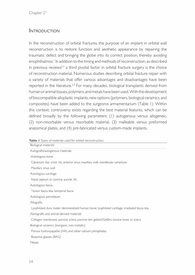
Chapter 23
54
intrOductiOn
In the reconstruction of orbital fractures, the purpose of an implant in orbital wall reconstruction is to restore function and aesthetic appearance by repairing the traumatic defect and bringing the globe into its correct position, thereby avoiding enophthalmos.1 In addition to the timing and methods of reconstruction, as described in previous reviews2,3 a third pivotal factor in orbital fracture surgery is the choice of reconstruction material. Numerous studies describing orbital fracture repair with a variety of materials that offer various advantages and disadvantages have been reported in the literature.2,3 For many decades, biological transplants derived from human or animal tissues, polymers, and metals have been used. With the development of biocompatible alloplastic implants, new options (polymers, biological ceramics, and composites) have been added to the surgeon›s armamentarium (Table 1). Within this context, controversy exists regarding the best material features, which can be defined broadly by the following parameters: (1) autogenous versus allogeneic, (2) non-resorbable versus resorbable material, (3) malleable versus preformed anatomical plates, and (4) pre-fabricated versus custom-made implants. Table 1 Types of materials used for orbital reconstruction.Biological materials
Autografts/autogenous materials
Autologous bone
Calvarium; iliac crest; rib, anterior sinus maxillary wall; mandibular symphysis
Maxillary sinus wall
Autologous cartilage
Nasal septum or concha; auricle; rib
Autologous fascia
Tensor fascia lata; temporal fascia
Autologous periosteum
Allografts
Lyophilized dura mater; demineralized human bone; lyophilized cartilage; irradiated fascia lata
Xenografts and animal-derived materials
Collagen membrane; porcine sclera; porcine skin gelatin/Gelfilm; bovine bone or sclera
Biological ceramics (inorganic, non-metallic)
Porous hydroxyapatite (HA) and other calcium phosphates
Bioactive glasses (BAG)
Metals
39372 Dubois, Leander.indd 54 04-03-16 10:19
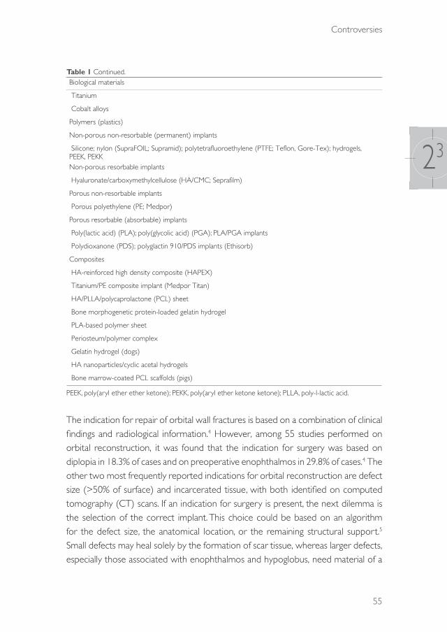
Controversies
55
23
Table 1 Continued.Biological materials
Titanium
Cobalt alloys
Polymers (plastics)
Non-porous non-resorbable (permanent) implants
Silicone; nylon (SupraFOIL; Supramid); polytetrafluoroethylene (PTFE; Teflon, Gore-Tex); hydrogels, PEEK, PEKKNon-porous resorbable implants
Hyaluronate/carboxymethylcellulose (HA/CMC; Seprafilm)
Porous non-resorbable implants
Porous polyethylene (PE; Medpor)
Porous resorbable (absorbable) implants
Poly(lactic acid) (PLA); poly(glycolic acid) (PGA); PLA/PGA implants
Polydioxanone (PDS); polyglactin 910/PDS implants (Ethisorb)
Composites
HA-reinforced high density composite (HAPEX)
Titanium/PE composite implant (Medpor Titan)
HA/PLLA/polycaprolactone (PCL) sheet
Bone morphogenetic protein-loaded gelatin hydrogel
PLA-based polymer sheet
Periosteum/polymer complex
Gelatin hydrogel (dogs)
HA nanoparticles/cyclic acetal hydrogels
Bone marrow-coated PCL scaffolds (pigs)
PEEK, poly(aryl ether ether ketone); PEKK, poly(aryl ether ketone ketone); PLLA, poly-l-lactic acid.
The indication for repair of orbital wall fractures is based on a combination of clinical findings and radiological information.4 However, among 55 studies performed on orbital reconstruction, it was found that the indication for surgery was based on diplopia in 18.3% of cases and on preoperative enophthalmos in 29.8% of cases.4 The other two most frequently reported indications for orbital reconstruction are defect size (>50% of surface) and incarcerated tissue, with both identified on computed tomography (CT) scans. If an indication for surgery is present, the next dilemma is the selection of the correct implant. This choice could be based on an algorithm for the defect size, the anatomical location, or the remaining structural support.5 Small defects may heal solely by the formation of scar tissue, whereas larger defects, especially those associated with enophthalmos and hypoglobus, need material of a
39372 Dubois, Leander.indd 55 04-03-16 10:19

Chapter 23
56
sufficient strength to support the orbital contents and restore the contour of the orbit.4
In defining the ideal characteristics of an orbital implant, many surgeons prefer materials that (1) allow bending to an anatomical shape, (2) are radiopaque, and (3) remain stable over time. The key question is what specific characteristics orbital implants should have to be beneficial for the different types of orbital fracture. While an increasing body of evidence is pointing to the importance of differentiated and complexity-based treatment models in general trauma surgery, this approach seems to fail for orbital fractures. For smaller defects (types I and II), the strength of the reconstruction material holds limited relevance for a successful outcome.6 Rather, the choice of material is more dependent on biocompatibility.5 In larger fractures (types III and IV), mechanical properties and the contour or form factor needs special consideration, as well as biocompatibility. The orbit remains a controversial entity in the human body with respect to the appropriate material for fracture repair. Today, the search for a material with ideal characteristics is ongoing (Table 2).
Table 2 Ideal orbital reconstruction material characteristics.
1. Stability and fixation Strong enough to support the orbital content and related forcesAbility to be stable and retain its shape once manipulatedNo deformation (sagging of material into maxillary sinus) under pressure loadStable over time
Possibility of being fixed to surrounding structures
2. Contouring and handling Restores adequate volume to treat enophthalmos, diplopia, and motility disordersEasy to shape to fit the orbital defect and regional anatomy/malleabilityAdequate in three-wall fracturesNo sharp edges and smooth surface
3. Biological behaviour Biocompatibility: no infection/extrusion/migration/foreign body reactionChemically inert, non-allergenic, non-carcinogenicDurable with minimal resorptionOsteoinductive/osteoconductiveHigh tissue incorporation but readily dissected in implant removal during secondary reconstruction
4. Drainage Spaces within the implant to allow drainage of orbital fluids5. Donor site morbidity Does not increase surgical complication rate/donor site morbidity (pain,
swelling, etc.)6. Radiopacity Radiopaque to enable radiographic evaluation without artefacts7. Availability and cost-
effectivenessReadily available in sufficient quantitiesAcceptable costs
39372 Dubois, Leander.indd 56 04-03-16 10:19

Controversies
57
23
The aims of this study were (1) to provide a comprehensive overview of the advantages and disadvantages of both traditional and new materials for the reconstruction of traumatic orbital defects, (2) to define the ideal characteristics of implant materials for future research, and (3) to offer evidence-based clinical recommendations regarding the best suitable material available.
advantages and disadvantages Of currently available recOnstructiOn Materials
Biological materialsBiological materials are defined as grafts harvested from the same or another human or animal and include autografts, allografts, and xenografts. Autologous grafts are characterized by cost-effectiveness but limited availability, variable resorption rates leading to unpredictable (orbital) volume, associated donor site morbidity (pain, scarring, infection, haematoma), and an increased surgical time. In the past, viral infections and other diseases (e.g. bovine spongiform encephalopathy and Creutzfeldt–Jakob disease) originating from the donor tissue have been reported for allografts and xenografts.
Since the 18th century, autologous bone has been the ‘gold standard’ biomaterial for the reconstruction of bony defects in the craniofacial area.7,8 Autologous bone grafts are used in orbital surgery because of their strength, rigidity, vascularization potential, and incorporation into the orbital tissues with minimal acute and chronic immune reactivity (i.e. infection, extrusion, collagenous capsule formation, and ocular tethering).9 Calvarial bone appears to be a superior option in orbital reconstruction because of its accessibility, the various graft sizes that can be harvested, the hidden nature of the scar as a result of its location in a hair-bearing area, and the occurrence of little or no postoperative pain.10 Donor site morbidity remains a general drawback for autologous bone harvesting. In full-thickness calvarial harvesting, care has to be taken not to tear the dura, since this injury carries the risk of iatrogenic subarachnoid haemorrhage or even intracerebral haemorrhage10 and might require reconstruction itself. Iliac crest grafting carries an associated risk of peritonitis, haemorrhage, pain, anterior spine fracture, lateral femoral cutaneous nerve damage, increased hospitalization time, and possibly thrombo-embolism.11 Additional disadvantages of autologous bone are the difficulty that can occur in contouring the bone to the perfect shape (e.g. because of fracturing of the graft
39372 Dubois, Leander.indd 57 04-03-16 10:19

Chapter 23
58
with bending). In addition, autologous bone grafting is associated with unpredictable resorption, especially rib and iliac bone, which are of endochondral origin.12 The latter is in contrast to calvarial bone, which is intramembranous in origin and is more stable. Resorption rates of 80% have been observed in iliac crest bone grafting.11 Resorption may be decreased by fixating of the graft, which promotes revascularization and osteoconduction.13
Despite the popularity of autologous bone, cartilage is easier to harvest and much more malleable, and the relative avascularity of this tissue allows survival with minimal oxygen perfusion and less resorption.14 The nasal septum is particularly advantageous because of the rapid harvest time and the minimal cosmetic and functional morbidity.15 Bayat et al.16 performed a randomized clinical trial (RCT) and found a superior effect for nasal cartilage versus conchal cartilage with respect to the occurrence of enophthalmos at the 3–6-month follow-up. A second RCT found no significant differences in the clinical outcomes of orbital fractures repaired with either a cartilage graft or an absorbable polyacid co-polymer.17 In cartilage grafting, limited donor site morbidity is involved. The major drawback of cartilage use is acquiring sufficient tissue for large orbital defects.
Allografts (syn. homografts) are transplanted tissues (e.g. lyophilized dura mater or banked (demineralized) bone) from another human being. Their advantages include a decreased surgical time, preoperative customizability, absence of donor site morbidity (only in cadavers), and abundant availability of banked (demineralized) bone.1 Lyophilized dura (Lyodura) was a standard in the past for the reconstruction of smaller orbital defects because of its strength and absence of tissue reactions.18 However, it became controversial following a case of Creutzfeldt–Jakob prion disease in a patient who received dura originating from a cadaver.19 Consequent to this report, lyophilized dura sterilization was no longer performed with gamma irradiation but with sodium hydroxide.20 The disadvantages of allografts include a resorption rate substantially higher than that of autologous tissue,9 the need for immunosuppressive pharmacotherapy, and the alleged risk of viral transmission, such as hepatitis C virus21 and HIV.22 Demineralized bone sheets of 100–300-μm thickness have been shown to be too weak to support orbital prolapse in cases with enophthalmos.23
The use of xenografts in bone reconstruction is generally not encouraged because it is associated with disease transmission, immunological transplant rejection, and unpredictable and high resorption rates.1 In contrast to biological materials, the use of manufactured implants saves operative time and avoids donor site morbidity.
39372 Dubois, Leander.indd 58 04-03-16 10:19
Controversies
59
23
MetalsTitanium has been used extensively in craniofacial surgery and dentistry in the form of implants, plates, and screws.24 With its high biocompatibility and physico-mechanical properties, it could be an ideal implant for covering large anatomical defects (categories III–V) and globe malposition if implant-stabilizing surrounding bone or a distal landmark (a ‘bony ledge’) is absent.2
An attractive feature of titanium is its ability to be both incorporated into the surrounding tissues and to osseointegrate.24 Titanium mesh seems to be particularly suitable for reconstructing large orbital fractures. Computer-assisted designed and manufactured (CAD/CAM) titanium implants have enabled optimal reconstructive surgery, with the protection of vital structures such as the optic nerve.25 Titanium is strong, rigidly fixable, widely available, and is subject to osseointegration with minimal foreign body reaction.26 However, titanium is costly and may have irregular edges if not cut properly, which may impinge soft tissue. Furthermore, fibrous tissue will incorporate the mesh-holes, which can make implant replacement technically complex.26 Late unwanted effects such as infection, corrosion, and toxic metal ion release have been reported with the use of titanium implants.24 One RCT has evaluated the effects of titanium implants as compared to perforated polydioxanone (PDS) foil for small orbital floor fracture reconstruction, and found no significant differences in the clinical outcomes.27 A pilot study without controls used a low-profile 0.25-mm titanium plate in large defects (categories II and III) and found successful clinical outcomes without complications in 93% of the cases; at the 6-month follow-up, no functional or aesthetic concerns were observed.28
Cobalt-based alloys such as vitallium are used widely in dentistry for their high resistance to corrosion. These alloys produce large artefacts on CT and magnetic resonance imaging (MRI) and have rarely been used in orbital surgery.29 These materials have been replaced by titanium in general prosthesiology.
PolymersPolymers (or plastics) are large molecules comprising multiple repeated subunits and can be categorized into absorbable and non-absorbable (permanent) types.
Non-absorbable permanent polymer implantsPorous ultra-high density polyethylene (PE; Medpor) sheets of various sizes and thicknesses (0.4–1.5 mm) have been used widely to cover smaller floor defects since the 1990s. This widespread use is a product of the ability to easily cut the
39372 Dubois, Leander.indd 59 04-03-16 10:19
Chapter 23
60
sheets into various shapes and the ability of orbital tissue to move freely over the smooth surface.30 Connective tissue and vascular components grow into the pores with minimal foreign body reaction.29 In a prospective cohort study of floor reconstructions, PE sheets showed satisfactory surgical outcomes and infection rates similar to autografts.5
Silicone is flexible, easy to handle, chemically inert, and relatively cheap.1 Silicone implants are substantially less palpable than non-silicone implants (autografts, titanium, or resorbable plates).31 However, unacceptably high rates of implant extrusion, cyst formation, and infections have been found, especially in the early postoperative period.32 Indeed, 12% of orbital silicone implants require removal within 1 month after placement.33
Polytetrafluoroethylene (PTFE; Teflon) is biologically and chemically inert, non-antigenic with minimal foreign body reaction, sterilizable, and easily mouldable. However, this polymer has not yet been subject to comparative clinical studies.
Relatively new in orbital floor repair is the use of nylon foil, a non-porous polyamide. Nylon foil has provided favourable results in preliminary non-comparative studies.34,35
Hydrogels are a network of hydrophilic polymer chains in a watery gel, and possess flexibility similar to natural tissue. Hydrogels have shown promising results in animal research in delivering bone morphogenetic protein type 2 (BMP-2) locally, significantly stimulating local bone growth.36
Absorbable polymer implantsThese materials have been used widely for over 30 years in many fields of surgical practice,37 and are of interest because of their more predictable absorption rates than biological grafts, as well as their high level of customizability and control.38 Resorbable materials provide temporary support, leaving fibrous granulation tissue during their degradation.39 These materials do not necessarily require rigid fixation, can be applied in multiple layers in larger orbital volume displacement, and can be radiolucent on postoperative imaging.
In an RCT, the administration of an absorbable copolymer of poly(lactic acid) (PLA) and poly(glycolic acid) (PGA) had functional and aesthetic outcomes and complications similar to auricular cartilage implants in orbital blowout fractures with or without medial wall involvement.17 In addition, PLA 70/30 plates were studied in a controlled clinical trial and showed similar surgical outcomes and complications as compared to autografts in category II and III floor defects, without MRI evidence of foreign body reaction.40
39372 Dubois, Leander.indd 60 04-03-16 10:19

Controversies
61
23
Polydioxanone (PDO, PDS) is used widely in surgery for resorbable sutures, which degrade completely in approximately 6 months. In a multi-centre RCT, perforated PDS foils of 0.15-mm thickness were found to have surgical outcomes similar to 0.3-mm titanium meshes in orbital floor reconstructions, although PDS foil was considered to be more convenient to handle.27 Another RCT compared the use of a porcine collagen membrane to a 0.15-mm PDS foil and observed that complications and clinical symptoms remained absent for 6 months after orbital floor surgery.41 In one prospective case series, PDS implants were suggested as inadvisable because of unsatisfactory orbital reconstructions and high complication rates.11
In a retrospective cohort study, reconstructions with polyglactin 910/PDS (Ethisorb) flexible patches showed a similar postoperative orbital geometry as compared to 0.25-mm PDS foil in floor reconstructions.42 In contrast to reports that polyglactin 910/PDS implants have high infection rates.43 A retrospective study of 87 patients treated with this material found no postoperative infections during a 3-month follow-up.39
Biological ceramicsHydroxyapatite (HA), which is chemically and crystallographically similar to bone mineral, has been available for craniofacial surgery since the 1990s.44 However, in orbital surgery, it has been found to be inferior to porous PE sheets with regard to the postoperative outcomes of enophthalmos.45
Bioactive glasses (BAGs) are synthetic blocks or granules that bond chemically to bone. The disadvantages of BAGs include their rather brittle nature and the lack of ease in moulding, shaping, and fixing them.46 Nonetheless, these materials have been demonstrated to be osteoinductive and osteoconductive as implants47 and to cause minimal foreign body reaction, infection, extrusion, displacement, and resorption.46,48 The benefits of preformed bioglass implants need further research.
CompositesAn interesting group of orbital implants is the composites because of the potential to utilize the advantages of a selected material while reducing its disadvantages through hybridization with a second material. A reciprocal process can allow the strengths of both materials to be used. A clinical example is titanium-reinforced PE. Titanium mesh offers the advantages of high strength and stability, easy contouring, and radiopacity in postoperative imaging, while PE implants have a smooth surface
39372 Dubois, Leander.indd 61 04-03-16 10:19
Chapter 23
62
allowing the free movement of orbital tissue. In recent years, a composite material (titanium-reinforced porous PE) has become available for maintaining ocular function and facilitating a secondary surgery if necessary.49 A retrospective chart review found no significant differences in the clinical outcome measures between PE channel implants versus PE-reinforced titanium implants. Kim et al.50 suggested that reinforced titanium PE implants do not require screw fixation.
A promising addition to polymers may be an extra coating. Heparinized bone marrow-coated polycaprolactone (PCL) scaffolds have shown promising potential in animal research, showing significantly greater bone induction in comparison to non-coated PCL scaffolds.51
To conclude, the predominant material investigated in the literature in the 1990s was autologous bone (45% bone versus 32% Medpor or titanium). A global trend towards the use of alloplastic material for orbital reconstruction can be identified. This trend is reflected in more recent publications, in which alloplastic materials have been chosen increasingly for orbital reconstruction (30% bone graft versus 46% alloplastic implants). This increasing preference for alloplastic materials is likely the result of their ease of use, technological advancements, absence of donor site morbidity, and an increasing level of evidence of the safety and efficacy of synthetic materials for this indication.52
the ideal iMPlant Material
IntroductionIn the search for the best material for orbital reconstruction, the most convenient approach may involve searching for the optimal material with reference to the fracture characteristics (e.g. fracture complexity, medical history, experience of the surgeon, costs). This approach could support a decision-making process for selecting an implant type based on typical fracture patterns. Seven material characteristics that would necessarily influence this clinical decision-making process are discussed (Table 3): (1) stability and fixation, (2) contouring abilities, (3) biological behaviour, (4) drainage, (5) donor site morbidity, (6) radiopacity, and (7) availability and cost-effectiveness. Future developments and new technologies are discussed as well.
39372 Dubois, Leander.indd 62 04-03-16 10:19

Controversies
63
23
Tabl
e 3
Adv
anta
ges
and
disa
dvan
tage
s of
com
mon
ly u
sed
biom
ater
ials.
Stab
ility
Con
tour
ing
Biol
ogic
al b
ehav
iour
Dra
inag
eD
onor
site
m
orbi
dity
Radi
opac
ityA
vaila
bilit
yC
ost-
effe
ctiv
enes
sTi
tani
um m
eshe
s (fl
at)
Sta
bilit
y +
++
++
con
tour
ing
++
allo
ws
tissu
e in
grow
th+
per
mea
ble
++
++
Fix
atio
n +
+−
pos
sible
sha
rp e
dges
− p
oor
diss
ectio
n of
per
i-orb
ita
in s
econ
dary
rec
onst
ruct
ion
Bone
gra
ft S
tabi
lity
++
+ v
aria
bilit
y in
thi
ckne
ss/
smoo
th s
urfa
ce a
dequ
ate
in t
hree
-wal
l fra
ctur
es
++
+ m
axim
al b
ioco
mpa
tibilit
y/pe
ri-or
bita
rea
dily
diss
ects
of
f bon
e in
sec
onda
ry
reco
nstr
uctio
n
−−
don
or s
ite
need
ed: h
arve
st
time/
pain
/sca
rrin
g/co
mpl
icat
ions
++
/−+
/−
Fix
atio
n +
− r
emod
ellin
g/di
fficu
lt to
sh
ape
Poro
us p
olye
thyl
ene
shee
ts S
tabi
lity+
−+
eas
ed b
y ar
tifici
al s
teril
e sk
ull/s
moo
th e
dges
++
allo
ws
tissu
e in
grow
th−
+−
not
vi
sible
on
post
oper
ativ
e im
agin
g
++
Lac
k of
rig
idity
whe
n th
inFi
xatio
n+/−
Com
posit
e of
por
ous
poly
ethy
lene
and
tita
nium
mes
h S
tabi
lity
++
+ e
ased
by
artifi
cial
ste
rile
skul
l, ade
quat
e in
thr
ee-
wal
l fra
ctur
es
++
allo
ws
tissu
e in
grow
th−
++
++
/− F
ixat
ion
++
Reso
rbab
le m
ater
ials
Stab
ility+
/−+
sm
ooth
sur
face
an
d ed
ges/
hand
ling
(the
rmop
last
ics)
+/−
ste
rile
infe
ctio
n/in
flam
mat
ory
resp
onse
− in
cas
e no
n-pe
rfora
ted:
le
ss d
rain
age
than
unc
over
ed
titan
ium
mes
h
+−
not
vi
sible
on
post
oper
ativ
e im
agin
g
++
Stab
le o
ver
time?
− n
on-t
herm
opla
stic
s F
ixat
ion+
/−−
deg
rada
tion
of m
ater
ial
with
risk
of c
onto
ur lo
ssPr
efor
med
orb
ital i
mpl
ant
Sta
bilit
y +
++
++
+ m
inim
al c
onto
urin
g ne
cess
ary/
smoo
th s
urfa
ce+
+ a
llow
s tis
sue
ingr
owth
+ p
erm
eabl
e+
++
+/−
Fix
atio
n +
+
39372 Dubois, Leander.indd 63 04-03-16 10:19

Chapter 23
64
Stability and fixationRestoring the original orbital volume is essential for recovering ocular function.53,54 To accomplish this, a reliable material that can reconstruct proper orbital volume and reposition the supporting tissues without significant resorption is required. Numerous materials have been used to achieve anatomical reconstruction and these differ with respect to their stability. Van Leeuwen et al.6 have developed a mathematical model to judge preoperatively whether a material is suitable based on four variables that influence deformation: (1) the size of the orbital defect, (2) the mechanical properties of the reconstruction material, (3) the thickness of the reconstruction material, and (4) the pressure load of the orbital content. Based on the properties of various biomaterials, the authors concluded that not all materials were suitable when varying defect sizes were considered.6 In particular, Jaquiéry category I and II defects can be treated safely with titanium, bone, PLA, and PE (see Table 4).6 For these small defects, a flexible material may generally be sufficient, whereas for the reconstruction of larger defects (Jaquiéry III and IV), a more rigid material (e.g. titanium) is required. Gross soft tissue prolapse, orbital pressure, and the absence of a posterior bony ledge are decisive factors.3,6
Table 4 Modified classification of orbital wall defect size.
Category Complexity Description NoteCategory I Low Isolated defect of the orbital floor
or the medial wall, 1–2 cm2, within zones 1 and 2
Category II Medium Defect of the orbital floor and/or of the medial wall, >2 cm2, within zones 1 and 2
Bony ledge preserved at the medial margin of the infraorbital fissure
Category III High Defect of the orbital floor and/or of the medial wall, >2 cm2, within zones 1 and 2
Missing bony ledge medial to the infraorbital fissure
Category IV High Defect of the entire orbital floor and the medial wall, extending into the posterior third (zone 3)
Missing bony ledge medial to the infraorbital fissure
Autologous bone is prone to resorption, possibly leading to loss of stability and contour over time. Resorption rates of up to 80% have been observed in iliac crest bone grafting.11 Resorption may be decreased by fixation of the graft, facilitating subsequent revascularization and osteoconduction.13
Resorbable implants are of interest because of their predictable resorption rates, high levels of customizability, and control.38 Resorbable materials provide temporary support, producing fibrous tissue during degradation.39 Van Leeuwen et
39372 Dubois, Leander.indd 64 04-03-16 10:19
Controversies
65
23
al.6 showed that the material properties of some resorbables are stable enough to support the orbital content. In contrast, others have demonstrated an increase in orbital volume as a late complication.11,55
For all orbital implants, fixation is required to prevent migration, which may lead to infections, fibrosis, and scarring, and may incidentally result in diplopia and even blindness.56–60 With the exception of bioglass, most orbital implant materials can be fixed easily to the surrounding tissue, mostly the bone. If the orbital rim is comminuted, fixation may be more complex. Titanium mesh may help to secure (or replace) the bony pieces.
ContouringThe size of the bony defect is important in choosing the alloplast material for reconstruction. Larger fractures have more variability in the defect shape, and failure to place the implant in a correct position might lead to atrophy, contractions, and herniated tissue.61 In most situations, unless pre-bent plates are used, the restoration of the complex anatomy of the orbit requires a significant effort in contouring the implant. Bony orbital walls are often comminuted, and bone fragments are often displaced into the maxillary sinus. In this context, reconstruction of the absent pieces of bone is essential to support the globe and restore orbital shape. CT is the single best method for imaging in orbital fractures and planning orbital reconstruction.62 Intraoperative and postoperative CT scanning aids the surgeon in evaluating the result of reconstruction. Suboptimal alignment of the implant does not necessarily lead to clinically relevant enophthalmos or diplopia.63 Nevertheless, anatomical reconstruction of the bony orbit is an important prerequisite for predictable reconstruction.2
Among the materials available, titanium mesh is the easiest material to shape anatomically, especially when an intraoperative skull model is used for adaptation of the implant. Ellis and Tan64 demonstrated that titanium mesh is architectonically more accurate in form than bone grafts. However, controversy exists in the use of preformed titanium mesh versus intraoperative bending of titanium meshes. A cadaver-based study found no significant differences in volume restoration between patient-specific implants (PSI) moulded on a pre-injury stereolithographic model, self-bent titanium meshes, and preformed titanium meshes.65 Preformed implants may be more advantageous because of versatility and costs.65 Andrades et al.63 concluded that pre-bent titanium implants are superior in terms of optimal reconstruction in comparison to other implants. In large defects (Jaquiéry III–IV), the implant contour
39372 Dubois, Leander.indd 65 04-03-16 10:19
Chapter 23
66
becomes an increasingly important factor for repositioning the globe into a correct position.66
Biological behaviourIn addition to being perfectly accepted by the acceptor area, autografts are both osteoconductive and osteoinductive if fixed properly, and elicit minimal foreign body reactions.9 However, autografts are associated with high resorption rates.13
Despite the popularity of autologous bone, cartilage is easier to harvest and much more malleable. Additionally, its hypovascularity allows survival with minimal oxygen perfusion, and this might explain why this tissue is less subject to resorption.14
The role of resorbable materials is to provide temporary support, leaving fibrous tissue during and after their degradation.39 Late inflammation reactions may occur even up to 3 years after surgery,67 and incomplete degradation and thick scar formation have been described. In particular, animal studies found that poly-l-lactic acid (PLLA) had not fully degraded within 5 years,68 while PDS degradation was associated with thick scar formation.11 PDS is not approved for orbital reconstruction in the USA because of the significant postoperative sequelae, including sensory disturbances (59%), restriction of motility (38%), and enophthalmos (24%).69
The stability of the position of non-resorbable implants is dependent on the degree of acute (e.g. sterile inflammation or infection) and chronic (capsulation, migration, extrusion) peri-orbital tissue reaction. Early integration in the acceptor area is advantageous for implant stability, but might decrease the possibility of removal in secondary reconstruction and replacement (e.g. if a fibrous capsule is present). Hence, the reconstruction may become increasingly technically complex.26
Bioactive glasses exhibit both osteoinductive and osteoconductive properties with little overall resorption46–48 Excessively large implants can alter the nutritional supply to the adjacent structures.70 The physical form of a material can increase the host response70–72
Titanium is highly biocompatible and the rate of postoperative infection is minimal.23,64 However, late unwanted effects such as corrosion and toxic metal ion release have been described.73,74 Currently, no allogeneic implant material exerts the ideal biological behaviour.
DrainageRetrobulbar haematoma is one of the most serious complications after orbital reconstruction. The reported incidence of retrobulbar haematoma in the literature
39372 Dubois, Leander.indd 66 04-03-16 10:19
Controversies
67
23
is about 0.6%.75 If postoperative impairment of vision due to retrobulbar haematoma becomes evident, an immediate surgical intervention is essential. It is more likely to occur in heavily traumatized patients with comminuted fractures and in patients taking anticoagulant medication.76 Both anticoagulant and anti-platelet therapies are likely to increase the risk of traumatic haemorrhage.77 Maurer et al.78 found that anticoagulant therapy was associated with a significantly increased risk of retrobulbar haematoma. In this previous study, the incidence of retrobulbar haematoma in patients on anticoagulant therapy with orbital fractures was 2.4%; this percentage increased to 8.8% in the geriatric group. Anti-platelet therapy alone (e.g. aspirin) did not increase the risk.79
No study has been published in the literature on the advantages of a permeable material that could drain a possible intra-orbital haemorrhage into the maxillary sinus or ethmoids. Perforations in an orbital implant can be beneficial in these cases. Titanium mesh probably has the best implant design because of its perforations, and it is suitable for large orbital wall defects, where most haemorrhage is seen.
Donor site morbidityBy choosing an autogenous graft for orbital reconstruction, the consequence is a second surgical site with its own specific after effects. There is the initial extra surgical time needed for the procedure, which can be reduced if the surgeons can work in two teams.
If the anterior iliac crest is selected, various complications can be encountered, including sensory disturbances, vascular injuries (e.g. bleeding or haematoma), seroma, fracture of the iliac crest, and accidental perforation of the lower abdomen. Postoperatively, gait disturbance together with pain at the donor site can occur. The pain experienced during mobilization can result in restricted activity and thereby lead to extra costs for both the patient and community.
Some surgeons prefer calvarial bone harvesting for orbital reconstructions because of the lower resorption rates and decreased postoperative pain.80 Complications encountered with calvarial bone grafts are alopecia along the incision line, bleeding from the incision site, and inner table perforations with or without dural tear. In the presence of damage to the dura, leakage of the cerebrospinal fluid will occur. In the worst case scenario, brain injury may occur.
Autologous cartilage grafts from the auricle are considered a relatively safe procedure with minor complication rates and favourable aesthetic outcomes.
39372 Dubois, Leander.indd 67 04-03-16 10:19

Chapter 23
68
Complications can include the formation of haematoma and sensory impairment confined to the concha (donor site). In terms of anthropometric measurements, resultant differences in the length and width of the affected ear, in the tragus–lateral canthus distance, and in the protrusion angle of the involved ear may occur. Overall, these findings are minor and are not considered a contraindication to harvesting ear cartilage.
RadiopacityThe accuracy of an anatomical reconstruction can be evaluated by peri- or postoperative imaging. Visibility of the implant material (bone or titanium) on CT scans is of immense importance in challenging injuries with severe dislocation of the orbital walls, e.g. in orbits with an absent posterior bony ledge. In these cases, limited visibility of the deep surgical field and the absence of a palpable ledge may cause the distal end of the plates to be placed too low (see Fig. 1). A good implant in a bad position will lead to a suboptimal result.63 To prevent poor implant positioning, accurate preoperative planning by mirroring a defined three-dimensional segment from the unaffected side onto the deformed/traumatized side with computer-assisted techniques is an important aid for precise and predictable results.81 Navigation can be beneficial, but imaging is the gold standard for peri- and postoperative evaluation of the position of the implant. Evaluation of the postoperative results is equally important for the learning curve of the surgeon and might help to predict postoperative enophthalmos.
Fig. 1 The orbital implant (titanium mesh) is positioned below the ledge, resulting in an increased orbital volume.
39372 Dubois, Leander.indd 68 04-03-16 10:19
Controversies
69
23
Availability and cost-effectivenessAvailability is a relative parameter related to economic and local circumstances and hospital interest and availability. Stocks of alloplasts can be limited in some parts of the world. Under these circumstances, the harvesting of bone grafts may be preferable, and in the case of orbital reconstruction, several options are available for the donor site. However, alloplasts reduce both the operation time and hospitalization because of the lack of donor site morbidity.
Pre-bent or preformed alloplastic materials are even more advantageous and have shortened the operating time compared to other alloplasts.65
Technological advantagesComputer-assisted surgery (CAS) may be beneficial to the outcome of orbital reconstruction. The use of three-dimensional reconstruction in CT imaging and virtual planning offers accurate and individualized assessment and planning for the restoration of orbital walls and orbital volume.82,83 Since more complex preoperative planning and intraoperative navigation have become available, it has been demonstrated repeatedly that CAS is helpful in achieving more predictability in orbital reconstruction.83,84 One of the greatest advantages of CAS is the possibility of checking the implant fit preoperatively in a digital environment. With stereolithographic files (stl) of pre-shaped implants, the best possible anatomical fit can be targeted. These digital stereolithographs may be pre-shaped or individually designed (PSI). This digital planning is not material-specific: the only prerequisite is that the material has rigidity such that the digitally formed shape is coherent with the actual shape of the implant, even after manipulation. To date, titanium mesh is most in concordance with this prerequisite. In the future, other modern materials such as bioglass, hydrogels, and poly-ether-ether cones and composites may be fabricated as custom implants or preformed scaffolds using new techniques for rapid prototyping.85,86
Clinical recommendationsThe debate on the clinical recommendations for orbital reconstruction material will likely continue because of the absence of RCTs and best practice clinical studies. The predominant factor regarding the most suitable material characteristic may be the defect size and to a lesser extent the defect location. Availability is also an important variable and is dependent on geographic and economic backgrounds. Nonetheless, based on the literature and material characteristics of the different types of orbital
39372 Dubois, Leander.indd 69 04-03-16 10:19
Chapter 23
70
implants, it is possible to derive clinical recommendations for materials in specific cases.
Treatment algorithm for orbital wall fractures1. Small-sized, low-complexity defects (class I): Most materials are
suitable; biological behaviour is most important and resorbables may be used in these cases.
2. Medium-sized, medium-complexity defects (class II): Apart from the biological behaviour of an implant, the experience of the surgeon with specific types of orbital implants will benefit the outcome. Various materials can be used, from autologous materials to alloplasts (e.g. PE or titanium).
3. Large-sized, high-complexity defects (classes III–IV): Stability and contour become more significant, and pre-bent or patient-specific titanium mesh is the preferred reconstruction material.
Further additional factors of influence are: (1) the chosen surgical approach (skin versus transconjunctival), (2) the need for simultaneous orbital rim reconstruction, which favours titanium, (3) costs, (4) operating time availability, with effective use of operating room time favouring the use of alloplasts, (5) patients on anticoagulant therapy will favour the use of mesh for drainage reasons, (6) experience of the surgeon in dealing with certain materials or in harvesting grafts, (7) the availability of modern planning tools (e.g. for PSI fabrication), (8) the availability of navigational surgery for stereolithographic virtual planning for .stl based on preformed titanium implants, and (9) the availability of intraoperative CT scanning.
39372 Dubois, Leander.indd 70 04-03-16 10:19

Controversies
71
23
references
1. Baino F. Biomaterials and implants for orbital floor repair, Acta Biomater 7, 2011, 3248–3266.
2. Dubois L, Steenen SA, Gooris PJ, Mourits MP, Becking AG. Controversies in orbital reconstruction—I. Defect-driven orbital reconstruction: a systematic review, Int J Oral Maxillofac Surg 44, 2015, 308–315.
3. Dubois L, Steenen SA, Gooris PJ, Mourits MP, Becking AG. Controversies in orbital reconstruction—II. Timing of orbital reconstruction in trauma: a systematic review, Int J Oral Maxillofac Surg 44, 2015, 433–440.
4. Gunarajah DR, Samman N. Biomaterials for repair of orbital floor blowout fractures: a systematic review, J Oral Maxillofac Surg 71, 2013, 550–570.
5. Wajih WA, Shaharuddin B, Razak NH. Hospital Universiti Sains Malaysia experience in orbital floor reconstruction: autogenous graft versus Medpor, J Oral Maxillofac Surg 69, 2011, 1740–1744.
6. van Leeuwen A, Ong SH, Vissink, Grijpma DW, Bos RR. Reconstruction of orbital wall defects: recommendations based on a mathematical model, Exp Eye Res 97, 2012, 10–18.
7. Tessier P, Woillez M, Lekieffre M, Asseman R. Posttraumatic diplopia and osseous grafts. Observations, Bull Mem Soc Fr Ophtalmol 73, 1960, 271–291.
8. Schlickewei W, Schlickewei C. The use of bone substitutes in the treatment of bone defects—the clinical view and history, Macromol Symp 253, 2007, 10–23.
9. Chowdhury K, Krausse GE., Selection of materials for orbital floor reconstruction, Arch Otolaryngol Head Neck Surg 124, 1998, 1398–1401.
10. Ilankovan V, Jackson IT. Experience in the use of calvarial bone grafts in orbital reconstruction, Br J Oral Maxillofac Surg 30, 1992, 92–96.
11. Kontio RK, Laine P, Salo A, Paukku P, Lindqvist C, Suuronen R. Reconstruction of internal orbital wall fracture with iliac crest free bone graft: clinical, computed tomography, and magnetic resonance imaging follow-up study, Plastic Reconstr Surg 118, 2006, 1365–1374.
12. Zins JE, Whitaker LA. Membranous versus endochondral bone: implications for craniofacial reconstruction, Plast Reconstr Surg 72, 1983, 778–785.
13. Glassman RD, Manson PN, Vanderkolk CA, Iliff NT, Yaremchuk MJ, Petty P, et al. Rigid fixation of internal orbital fractures, Plast Reconstr Surg 86, 1990, 1103–1111.
14. Castellani A, Negrini S, Zanetti U. Treatment of orbital floor blowout fractures with conchal auricular cartilage graft: a report on 14 cases, J Oral Maxillofac Surg 60, 2002, 1413–1417.
15. Lai A, Gliklich RE, Rubin PAD. Repair of orbital blow-out fractures with nasoseptal cartilage, Laryngoscope 108, 1998, 645–650.
16. Bayat M, Momen-Heravi F, Khalilzadeh O, Mirhosseni Z, Sadeghi-Tari A. Comparison of conchal cartilage graft with nasal septal cartilage graft for reconstruction of orbital floor blowout fractures, Br J Oral Maxillofac Surg 48, 2010, 617–620.
17. Kruschewsky S, Novais T, Daltro C, Castelo Branco B, Lessa M, Kruschewsky MB, et al., Fractured orbital wall reconstruction with an auricular cartilage graft or absorbable polyacid copolymer, J Craniofac Surg 22, 2011, 1256–1259.
18. Luhr HG, Maerker R. Transplantation of homologous dura in reconstruction of the orbital floor. The results of five years experience, Trans Int Conf Oral Surg 4, 1973, 340–344.
19. Prichard JV, Thadani R, Kalb E.Rapidly progressive dementia in a patient who received a cadaveric dura mater graft, JAMA 257, 1987, 1036.
20. Guerra MF, Pérez JS, Rodriguez-Campo FJ, Gías LN. Reconstruction of orbital fractures with dehydrated human dura mater, J Oral Maxillofac Surg 58, 2000, 1361–1366.
21. Aho AJ, Hirn M, Aro HT, Heikkilä JT, Meurman O. Bone bank service in Finland. Experience of bacteriologic, serologic and clinical results of the Turku Bone Bank 1972–1995, Acta Orthop Scand 69, 1998, 559–565.
22. Campbell DG, Li P. Sterilization of HIV with irradiation: relevance to infected bone allografts, Aust N Z J Surg 69, 1999, 517–521.
23. Sallam MM, Hashem HA, Shokier HM. Use of demineralized bone sheets in reconstruction of orbital floor trap door fracture, J Appl Sci Res 6, 2010, 653–658.
24. Mackenzie DJ, Arora B, Hansen J. Orbital floor repair with titanium mesh screen, J Craniomaxillofac Trauma 5, 1999, 9–18.
39372 Dubois, Leander.indd 71 04-03-16 10:19

Chapter 23
72
25. Lieger O, Richards R, Liu M, Lloyd T. Computer-assisted design and manufacture of implants in the late reconstruction of extensive orbital fractures, JAMA Facial Plast Surg 12, 2010, 186–191.
26. Schubert W, Gear AJ, Lee, Hilger PA, Haus E, Migliori MR, et al. Incorporation of titanium mesh in orbital and midface reconstruction, Plast Reconstr Surg 110, 2002, 1022–1032.
27. Dietz A, Ziegler CM, Dacho A, Althof F, Conradt C, Kolling G, et al. Effectiveness of a new perforated 0.15 mm poly-p-dioxanon-foil versus titanium-dynamic mesh in reconstruction of the orbital floor, J Maxillofac Surg 29, 2001, 82–88.
28. Lieger O, Schaller B, Zix J, Kellner F, Iizuka T. Repair of orbital floor fractures using bioresorbable poly l/dl-lactide plates, Arch Facial Plast Surg 12, 2010, 399–404.
29. Sullivan PK, Smith JF, Rozzelle A. Cranio-orbital reconstruction: safety and image quality of metallic implants on CT and MRI scanning, Plast Reconstr Surg 94, 1994, 589–596.
30. Dougherty WR, Wellisz T. The natural history of alloplastic implants in orbital floor reconstruction: an animal model, J Craniofac Surg 5, 1994, 26–33.
31. Prowse SJ, Hold PM, Gilmour RF, Pratap U, Mah E, Kimble FW. Orbital floor reconstruction: a case for silicone. A 12 years experience, J Plast Reconstr Aesthet Surg 63, 2010, 1105–1109.
32. Laxenaire A, Levy J, Blanchard P, Lerondeau JC, Tesnier F, Scheffer P. Complications of silastic implants used in orbital repair, Rev Stomatol Chir Maxillofac 98 (Suppl. 1), 1997, 96–99.
33. Morrison AD, Sanderson RC, Moos KF. The use of silastic as an orbital implant for reconstruction of orbital wall defects: review of 311 cases treated over 20 years, J Oral Maxillofac Surg 53, 1995, 412–417.
34. Nunery WR, Tao JP, Johl S. Nylon foil ‘wraparound’ repair of combined orbital floor and medial wall fractures, Ophthal Plast Reconstr Surg 24, 2008, 271–275.
35. Park DJ, Garibaldi DC, Iliff NT, Grant MP, Merbs SL. Smooth nylon foil (SupraFOIL) orbital implants in orbital fractures: a case series of 181 patients, Ophthal Plast Reconstr Surg 24, 2008, 266–270.
36. Betz MW, Caccamese JF, Coletti DP, Sauk JJ, Fisher JP. Tissue response and orbital floor regeneration using cyclic acetal hydrogels, J Biomed Mater Res A 90, 2009, 819–829.
37. Francel TJ, Bireley BC, Ringelman PR, Manson PN. The fate of plates and screws after facial fracture reconstruction, Plast Reconstr Surg 90, 1992, 568–573.
38. Lyu SP, Untereker D. Degradability of polymers for implantable biomedical devices, Int J Mol Sci 10, 2009, 4033–4065.
39. Büchel P, Rahal A, Seto I, Iizuka T. Reconstruction of orbital floor fracture with polyglactin 910/polydioxanon patch (Ethisorb): a retrospective study, J Oral Maxillofac Surg 63, 2005, 646–650.
40. Al-Sukhun J, Lindqvist C. A comparative study of 2 implants used to repair inferior orbital wall bony defects: autogenous bone graft versus bioresorbable poly-l/dll/dl-lactide [P(L/DL)LA 70/30] plate, J Oral Maxillofac Surg 64, 2006, 1038–1048.
41. Becker ST, Terheyden H, Fabel M, Kandzia C, Möller B, Wiltfang J. Comparison of collagen membranes and polydioxanone for reconstruction of the orbital floor after fractures, J Craniofac Surg 21, 2010, 1066–1068.
42. Gerressen M, Gillessen S, Riediger D, Hölzle F, Modabber A, Ghassemi A. Radiologic and facial morphologic long-term results in treatment of orbital floor fracture with flexible absorbable alloplastic material, J Oral Maxillofac Surg 70, 2012, 2375–2385.
43. Avashia YJ, Sastry A, Fan KL, Mir HS, Thaller SR. Materials used for reconstruction after orbital floor fracture, J Craniofac Surg 23, 2012, 1991–1997.
44. Mathur KK, Tatum SA, Kellman RA. Carbonated apatite and hydroxyapatite in craniofacial reconstruction, Arch Facial Plast Surg 5, 2003, 379–383.
45. Nam SB, Bae YC, Moon JS, Kang YS. Analysis of the postoperative outcome in 405 cases of orbital fracture using 2 synthetic orbital implants, Ann Plast Surg 56, 2006, 263–267.
46. Peltola M, Kinnunen I, Aitasalo K. Reconstruction of orbital wall defects with bioactive glass plates, J Oral Maxillofac Surg 66, 2008, 639–646.
47. Heikkilä JT, Aho HJ, Yli-Urpo A, Happonen RP, Aho AJ. Bone formation in rabbit cancellous defects filled with bioactive glass granules, Acta Orthop Scand 66, 1995, 463–467.
48. Aitasalo K, Kinnunen I, Palmgren J , Varpula M. Repair of orbital floor fractures with bioactive glass implants, J Oral Maxillofac Surg 59, 2001, 1390–1396.
39372 Dubois, Leander.indd 72 04-03-16 10:19

Controversies
73
23
49. Merbs SL, Iliff NT, Grant MT, Garibaldi DC. Use of MEDPOR TITAN implants in orbital reconstruction, Invest Ophthalmol Vis Sci 46, 2005, E4210.
50. Kim CT, Jeong BJ, Lee SY, Yoon JS. Comparison of surgical outcome of large orbital fractures reconstructed with porous polyethylene channel and porous polyethylene titan barrier implants, Ophthal Plast Reconstr Surg 28, 2012, 176–180.
51. Rohner D, Hutmacher DW, Cheng TK, Oberholzer M, Hammer B. In vivo efficacy of bone-marrow-coated polycaprolactone scaffolds for the reconstruction of orbital defects in pigs, J Biomed Mater Res B Appl Biomater 66, 2003, 574–580.
52. Aldekhayel S, Aljaaly H, Fouda-Neel O, Shararah AW, Zaid WS, Gilardino M. Evolving trends in the management of orbital floor fractures, J Craniofac Surg 25, 2014, 258–261.
53. Bite U, Jackson IT, Forbes GS, Gehring DG. Orbital volume measurements in enophthalmos using three-dimensional CT imaging, Plast Reconstr Surg 75, 1985, 502–508.
54. Manson PN, Clifford CM, Su CT, Iliff NT, Morgan R. Mechanisms of global support and posttraumatic enophthalmos: I. The anatomy of the ligament sling and its relation to intramuscular cone orbital fat, Plast Reconstr Surg 77, 1986, 193–202.
55. Cordewener FW, Bos RR, Rozema FR, Houtman WA. Poly(ll-lactide) implants for repair of human orbital floor defects: clinical and magnetic resonance imaging evaluation of long-term results, J Oral Maxillofac Surg 54, 1996, 9–14.
56. Aronowitz JA, Freeman BS, Spira M. Long-term stability of Teflon orbital implants, Plast Reconstr Surg 78, 1986, 166–173.
57. Haug RH, Kimberly D, Bradick JP. A comparison of microscrew and suture fixation of porous high density polyethylene orbital floor implants, J Oral Maxillofac Surg 51, 1993, 1217–1220.
58. Browning C. Alloplastic materials in orbital repair, Am J Ophthalmol 63, 1967, 955–962.
59. Polley JW, Ringler SL. The use of Teflon in orbital floor reconstruction following blunt facial trauma: a 20-year experience, Plast Reconstr Surg 79, 1987, 39–43.
60. Lin KY, Bartlett SP, Yaremchuck MJ, Fallon M, Grossman RF, Whitaker LA. The effect of rigid fixation on the survival of onlay bone graft: an experimental study, Plast Reconstr Surg 86, 1990, 449–456.
61. Potter JK, Ellis E. Biomaterials for reconstruction of the internal orbit. J Oral Maxillofac Surg 62, 2004, 1280-97.
62. Chen CT, Chen YR. Update on orbital reconstruction, Curr Opin Otolaryngol Head Neck Surg 18, 2010, 311–316.
63. Andrades P, Hernandez D, Falguera MI, Millan JM, Heredero S, Gutierrez R, et al. Degrees of tolerance in post-traumatic orbital volume correction: the role of prefabricated mesh, J Oral Maxillofac Surg 67, 2009, 2404–2411.
64. Ellis E, Tan Y. Assessment of internal orbital reconstructions for pure blowout fractures: cranial bone grafts versus titanium mesh, J Oral Maxillofac Surg 61, 2003, 442–453.
65. Strong EB, Fuller SC, Wiley DF, Zumbansen J, Wilson MD, Metzger MC. Preformed vs intraoperative bending of titanium mesh for orbital reconstruction, Otolaryngol Head Neck Surg 149, 2013, 60–66.
66. Jaquiéry C, Aeppli C, Cornelius P, Palmowsky A, Kunz C, Hammer B. Reconstruction of orbital wall defects: critical review of 72 patients, Int J Oral Maxillofac Surg 36, 2007, 193–199.
67. Bergsma EJ, Rozema FR, Bos RR, de Bruijn WC. Foreign body reactions to resorbable poly(ll-lactide) bone plates and screws used for the fixation of unstable zygomatic fractures, J Oral Maxillofac Surg 51, 1993, 666–670.
68. Bos RR, Boering G, Rozema FR, Leenslag JW. Resorbable poly(ll-lactide) plates and screws for the fixation of zygomatic fractures, J Oral Maxillofac Surg 45, 1987, 751–753.
69. Enislidis G. Treatment of orbital fractures: the case for treatment with resorbable materials, J Oral Maxillofac Surg 62, 2004, 869–872.
70. Davila JC, Lautsch EV, Palmer TE. Some physical factors affecting the acceptance of synthetic materials as tissue implants, Ann N Y Acad Sci 146, 1968, 138–147.
71. Brown AE, Banks P. Late extrusion of alloplastic orbital floor implants, Br J Oral Maxillofac Surg 31, 1993, 154–157.
72. Sewall SR, Pernoud FG, Pernoud MJ. Late reaction to silicone following reconstruction of an orbital floor fracture, J Oral Maxillofac Surg 44, 1986, 821–825.
39372 Dubois, Leander.indd 73 04-03-16 10:19
Chapter 23
74
73. Andreiotelli M, Wenz HJ, Kohal RJ. Are ceramic implants a viable alternative to titanium implants? A systematic literature review, Clin Oral Implants Res 20 (Suppl. 4), 2009, 32–47.
74. Adya N, Alam M, Ravindranath T, Mubeen A, Saluja B. Corrosion in titanium dental implants: literature review, J Indian Prosthodont Soc 5, 2005, 125–131.
75. Hislop WS, Dutton GN, Douglas PS. Treatment of retrobulbar haemorrhage in accident and emergency departments, Br J Oral Maxillofac Surg 34, 1996, 289–292.
76. Gosau M, Schöneich M, Draenert FG, Ettl T, Driemel O, Reichert TE. Retrospective analysis of orbital floor fractures—complications, outcome, and review of literature, Clin Oral Investig 15, 2011, 305–313.
77. Segal JB, McNamara RL, Miller MR, Powe NR, Goodman SN, Robinson KA, et al., Anticoagulants or antiplatelet therapy for non-rheumatic atrial fibrillation and flutter, Cochrane Database Syst Rev 3, 2006, CD001938.
78. Maurer P, Conrad-Hengerer I, Hollstein S, Mizziani T, Hoffmann E, Hengerer F. Orbital haemorrhage associated with orbital fractures in geriatric patients on antiplatelet or anticoagulant therapy, Int J Oral Maxillofac Surg 42, 2013, 1510–1514.
79. Scheerlinck LM, Muradin MS, van der Bilt A, Meijer GJ, Koole R, van Cann EM. Donor site complications in bone grafting: comparison of iliac crest, calvarial, and mandibular ramus bone, Int J Oral Maxillofac Implants 28, 2013, 222–227.
80. Mischkowski RA, Selbach I, Neugebauer J, Koebke J, Zöller JE. Lateral femoral cutaneous nerve and iliac crest bone grafts—anatomical and clinical considerations, Int J Oral Maxillofac Surg 35, 2006, 366–372.
81. Zizelmann C, Gellrich NC, Metzger MC, Schoen R, Schmelzeisen R, Schramm A. Computer-assisted reconstruction of orbital floor based on cone beam tomography, Br J Oral Maxillofac Surg 45, 2007, 79–80.
82. Bratton EM, Durairaj VD. Orbital implants for fracture repair, Curr Opinion Ophthalmol 22, 2011, 400–406.
83. Schramm A, Suarez-Cunqueiro MM, Rücker M, Kokemueller H, Bormann KH, Metzger MC, et al., Computer-assisted therapy in orbital and mid-facial reconstructions, Int J Med Robot 5, 2009, 111–124.
84. Rana M, Essig H, Rücker M, Gellrich NC. Development and demonstration of a novel computer planning solution for predefined correction of enophthalmos in anophthalmic patients using prebended 3D titanium-meshes—a technical note, J Oral Maxillofac Surg 70, 2012, e631–e638.
85. Bergmann M, Lindner M, Zhang W, Koczur K, Kirsten A, Telle R, et al., 3D printing of bone substitute implants using calcium phosphate and bioactive glasses, J Eur Ceram Soc 30, 2010, 2563–2567.
86. Quadrani P, Pasini A, Mattiolli-Belmonte M, Zannoni C, Tampieri A, Landi A, et al., High-resolution 3D scaffold model for engineered tissue fabrication using a rapid prototyping technique, Med Biol Eng Comput 43, 2005, 196–199
39372 Dubois, Leander.indd 74 04-03-16 10:19

39372 Dubois, Leander.indd 75 04-03-16 10:19

39372 Dubois, Leander.indd 76 04-03-16 10:19

dIAGNOSTICS
39372 Dubois, Leander.indd 77 04-03-16 10:19

39372 Dubois, Leander.indd 78 04-03-16 10:19

CHAPTER 3How reliable is the visual appraisal of a surgeon for diagnosing orbital
fractures?
This chapter is an edited version of the manuscript: Dubois L, Jansen J, Schreurs R, Habets PEM, Reinartz SM, Gooris PJJ, Becking AG. How reliable is the visual appraisal of a surgeon for diagnosing orbital fractures?
J Craniomaxillofac Surg. 2016 (submitted)
39372 Dubois, Leander.indd 79 04-03-16 10:19

Chapter 3
80
1. intrOductiOn
The goals of orbital reconstruction surgery include repair of the traumatic defect and restoration of ocular function by lifting the globe into position and elevating the dislocated and sometimes incarcerated soft tissue in order to avoid clinical symptoms such as enophthalmos, hypoglobus, and diplopia. Unfortunately, clinical decision making with regard to the management of patients with orbital fractures can be challenging.1-4 The indications for surgical intervention and the choice of implant material are directly influenced by the complexity of the case. Larger and more complex fractures are more susceptible to adverse treatment outcomes and require a different treatment protocol than small and solitary orbital wall fractures.1,3,5-9 For example, if >50% of the surface area of the orbital medial wall or floor is missing, the risk of developing enophthalmos is considerable, which enhances the need for surgical correction. However, the reliability of this indicator remains questionable.
Once an indication for surgery is established, the first step in orbital reconstruction is to estimate the size and location of the defect. This helps the surgeon to select the most suitable reconstruction material. In conventional orbital reconstruction, implants that can be manually bent require intraoperative adjustment to match the specific orbital defect. Consequently, the surgeon is forced to estimate the length, width, and surface area of the defect before adjusting the implant. Estimation errors may lead to incorrect dimensions and positioning of the orbital implant and a poor clinical outcome.
Computed tomography (CT) is recognized as the best imaging technique for evaluating orbital fractures.10-14 Additionally, software-based, virtual, three-dimensional (3D) reconstructions help surgeons with the decision-making process,12,13,15 resulting in more rational choices. Systematic reviews on orbital reconstruction have revealed that surgeons based their surgery-related decisions on CT findings (fracture size, incarcerated tissue) in almost half of the cases analyzed.2,16 Such reviews suggest that in approximately 19% of cases, a CT finding of a fracture involving >50% of the surface area was a primary indicator for orbital reconstruction.5,16
The newest technology in orbital reconstruction is computer-assisted surgery (CAS), which includes a preoperative diagnostic and planning phase, an image-guided navigation phase, and an intraoperative control phase. The first phase allows
39372 Dubois, Leander.indd 80 04-03-16 10:19

Diagnostics
81
3
the surgeon to use all of the information in the Digital Imaging and Communications in Medicine (DICOM) dataset. The original anatomy can be simulated using segmentation and mirroring tools.17,18 This additional information is beneficial for optimizing diagnostics,19 and contributes greatly to the surgeon’s preparation before the actual procedure is performed. Stereolithographic (stl) files of preformed or patient-specific implants can be fitted in the digital environment, and with the integration of intraoperative navigation and imaging in the treatment protocol, this aids to optimalization.20-23 Unfortunately, these technological possibilities are only available in select, well-equipped centers. Even though the amount of extra time required for CAS is not excessive,17,22 some surgeons prefer to rely on their experience to achieve an acceptable result. However, recently published studies suggest that experience does not always lead to better diagnoses24,25 or consistent results.21,22,26-29
The aim of this study was to compare direct intraoperative and endoscopic visualization with CT observations to identify the most reliable method for determining the size, location, and complexity of orbital fractures. The effect of the surgeon’s experience on the accuracy of the estimations was also assessed.
2. MethOds
Ten human cadaver heads were obtained from the body donation program of the Department of Anatomy, Embryology, and Physiology at the Academic Medical Center of the University of Amsterdam. Institutional review board approval was waived for this study. One of the 20 orbits was excluded due to sinus pathology (osteoma); thus, 19 orbits were used in this study. Each head was labeled. The orbital floor and medial wall were fully exposed via a standard transconjunctival incision and retroseptal preparation. Using the Jaquiéry classification system6,30 (Figure 1), class I to IV orbital defects were created by piezoelectric surgery (Mectron, Carasco, Italy). Via a buccogingival incision, a 5-mm antrostomy was created by piezoelectric surgery in the concavity of the canine fossa to facilitate inspection with a 0° or 30° rigid endoscope. The overlying sinus mucosa was removed.
39372 Dubois, Leander.indd 81 04-03-16 10:19

Chapter 3
82
Figure 1. Classification of orbital fractures according to the Jaquiéry system.
Four surgeons (three oral and maxillofacial surgeons, one otolaryngologist), and one anatomist used six different observation methods to visualize and describe the orbital defect sizes and locations, as follows: (1) transconjunctival approach (direct intraoperative visualization), (2) transantral endoscopic approach with a 0° scope, (3) transantral endoscopic approach with a 30° scope, (4) transconjunctival endoscopic approach with a 0° scope, (5) estimation based on CT images only (without the aid of software), and (6) digital measurements on CT images (with the aid of software).
The assessors were blind with regard to the specimen numbers. Each observer was instructed to perform a standardized examination of each fracture by using one of the observation methods listed above. For the transconjunctival observations, both the inferior orbital fissure and the transition zone between the floor and medial wall needed to be located. Before endoscopic observation, all
39372 Dubois, Leander.indd 82 04-03-16 10:19

Diagnostics
83
3
Figure 2. Defining fracture size. (a) Coronal view. (b) Sagittal view. (c) Three-dimensional view.
observers were asked to identify the following three landmarks to aid in orientation: the infraorbital nerve, sinus ostia, and posterior shelf (as defined by Moore et al.).31 Then, they were asked to assess the fracture and record its location, size (length, width, and surface area), and classification.
CT analysis CT scans (Sensation 64; Siemens Medical Solutions, Forchheim, Germany) of the cadaver heads were acquired with intact orbits (baseline, T0) and after the creation of the orbital defects (T1). The scanning parameters were as follows: collimation, 20.0 × 0.6 mm; 120 kV; 350 mAs; pitch, 0.85; field of view, 30 cm; matrix size, 512 × 512; reconstruction slice thickness, 0.75 mm with overlapping increments of 0.4 mm; bone kernel, H70s; and bone window, W1600 L400. DICOM data for the T0 and T1 scans
39372 Dubois, Leander.indd 83 04-03-16 10:19

Chapter 3
84
were imported into iPlan version 3.0.5 (Brainlab AG, Feldkirchen, Germany). The image volumes were fused using the image fusion function. Atlas-based segmentation of the intact orbit was performed using the T0 scans, whereas the border of the defect was segmented based on information from the T0 and fused T1 scans.
The segmentations of the bony orbit and defect outline were exported as .stl files and imported into 3DS Max version 2012 (Autodesk Inc., San Rafael, CA, USA). The surface area of the intact orbit was extracted from the model based on the outline of the segmented defect (Figure 2). Length, width, and surface area measurements of the extracted object, representing the surface area of the orbit on the T0 scan at the location of the defect on the T1 scan were obtained and considered to be the actual defect dimensions.
Statistical analysisThe observers estimated the maximal sagittal distance (length), transverse distance (width), surface area, and Jaquiéry classification of each fracture using the six observation methods listed above. Statistical analysis was performed using SPSS version 21.0 (IBM Corp., Armonk, NY, USA). Interobserver agreement was calculated using the intraclass correlation coefficient (ICC), where an ICC of 0 indicates no agreement, while an ICC of 1 indicates perfect agreement. The paired-samples t-test was performed to assess the significance of the differences between the measurements obtained using the different observation methods and the differences between the two-dimensional (2D) and 3D surface area measurements.
3. results
The orbital floor and medial wall defects ranged in size from 0.9–5.7 cm2.
Consistency and accuracy The ICCs were calculated to assess the consistency of the variables. Table 1 shows the ICCs of the defect measurements obtained with the different observation methods. The differences between the individual observations and the real defect sizes (length, width, and surface area) were used to analyze the accuracy of the observations. A stacked-column chart presented in Figure 3 shows the correct estimations within 0.5 cm and 1.0 cm of the true value.
39372 Dubois, Leander.indd 84 04-03-16 10:19

Diagnostics
85
3
Table 1. ICCs and corresponding 95% CIs for length, width, and surface area
Length Width Surface area
Over/underestimation,
%
Over/underestimation,
%
Over/underestimation,
%Method ICC 95% CI ICC 95%
CIICC 95% CI
Direct transconjunctival
0.787 0.585–0.907
105 0.830 0.668–0.926
120 0.793 0.598–0.910
176
Transantral 0o scope
0.778 0.567–0.903
85 0.824 0.657–0.923
109 0.758 0.529–0.895
129
Transantral 30o scope
0.743 0.501–0.888
84 0.828 0.666–0.925
107 0.825 0.660–0.924
123
Transconjunctival 0o scope
0.666 0.350–0.855
107 0.781 0.575–0.905
121 0.735 0.484–0.885
184
CT measurement
0.832 0.674–0.927
91 0.910 0.825–0.961
102 - - -
CT estimation 0.883 0.773–0.949
93 0.834 0.677–0.928
110 0.932 0.867–0.970
121
Abbreviations: CI, confidence interval; CT, computed tomography; ICC, interclass correlation coefficient.
Figure 3. Stacked-column chart, showing observation-based estimations accurate to within 0.5 (a) and 1.0 (b) cm.
LengthThe observations with the 0° and 30° endoscopes resulted in mean underestimations of 15% and 16%, respectively, for the maximum length in the anteroposterior direction, while direct intraoperative visualization (transconjunctival approach) resulted in overestimation by an average of 5%. The use of an additional endoscope
39372 Dubois, Leander.indd 85 04-03-16 10:19
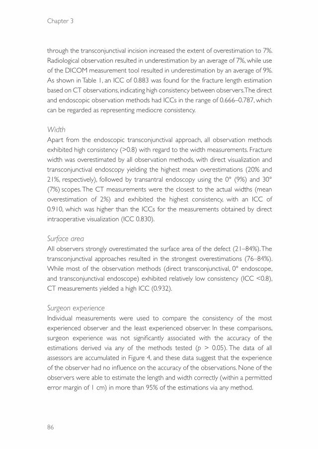
Chapter 3
86
through the transconjunctival incision increased the extent of overestimation to 7%. Radiological observation resulted in underestimation by an average of 7%, while use of the DICOM measurement tool resulted in underestimation by an average of 9%. As shown in Table 1, an ICC of 0.883 was found for the fracture length estimation based on CT observations, indicating high consistency between observers. The direct and endoscopic observation methods had ICCs in the range of 0.666–0.787, which can be regarded as representing mediocre consistency.
WidthApart from the endoscopic transconjunctival approach, all observation methods exhibited high consistency (>0.8) with regard to the width measurements. Fracture width was overestimated by all observation methods, with direct visualization and transconjunctival endoscopy yielding the highest mean overestimations (20% and 21%, respectively), followed by transantral endoscopy using the 0° (9%) and 30° (7%) scopes. The CT measurements were the closest to the actual widths (mean overestimation of 2%) and exhibited the highest consistency, with an ICC of 0.910, which was higher than the ICCs for the measurements obtained by direct intraoperative visualization (ICC 0.830).
Surface areaAll observers strongly overestimated the surface area of the defect (21–84%). The transconjunctival approaches resulted in the strongest overestimations (76–84%). While most of the observation methods (direct transconjunctival, 0° endoscope, and transconjunctival endoscope) exhibited relatively low consistency (ICC <0.8), CT measurements yielded a high ICC (0.932).
Surgeon experienceIndividual measurements were used to compare the consistency of the most experienced observer and the least experienced observer. In these comparisons, surgeon experience was not significantly associated with the accuracy of the estimations derived via any of the methods tested (p > 0.05). The data of all assessors are accumulated in Figure 4, and these data suggest that the experience of the observer had no influence on the accuracy of the observations. None of the observers were able to estimate the length and width correctly (within a permitted error margin of 1 cm) in more than 95% of the estimations via any method.
39372 Dubois, Leander.indd 86 04-03-16 10:19

Diagnostics
87
3
Figure 4. Stacked-column chart, showing assessor experience and estimations accurate to within 0.5 cm for direct transconjunctival observations (a) and computed tomographic measurements (b).
Jaquiéry classificationThe complexity of the fractures was scored with the Jaquiéry classification system (Table 2). Even for the more experienced oral and maxillofacial surgeons, the proportion of accurately scored fractures ranged from 40.6% to 57.6%. The method that resulted in the most accurate scoring was the transconjunctival approach using a 0° scope. An unclear view of the posterior ledge and overestimation/underestimation of the size and location of the defect were important factors contributing to the inconsistent classifications, and there was a tendency to classify class I, III, and IV fractures as class II fractures.
Table 2. Correct estimations of fracture complexity according to the Jaquiéry system (%)
Observed
Fracture class 1 2 3 4
1 64 32 3 1
2 30 48 12 10
3 10 32 35 22
4 3 29 16 50
2D vs. 3D surface area measurements on CT dataTable 3 shows the 2D and 3D surface area measurements (Figure 5). Curvature of the orbit was significantly associated with increased surface area measurements
39372 Dubois, Leander.indd 87 04-03-16 10:19

Chapter 3
88
of the defect (p < 0.05). Even for small defects (<2.8 cm2), the mean surface area derived with 3D measurements was significantly larger than that derived with 2D measurements (p < 0.0001).
Table 3. Two- and three-dimensional surface area measurements (mean ± SD)
Surface area, cm² 2D 3D Δ 95% CI p value
Overall 2.25 ± 1.0 2.83 ± 1.3 0.58 ± 0.40 0.39–0.77 0.000006
Small defects (<2.8 cm²) 1.36 ± 0.4 1.70 ± 0.5 0.34 ± 0.13 0.25–0.45 0.000043
Large defects (>2.8 cm²) 3.06 ± 0.6 3.85 ± 0.9 0.79 ± 0.45 0.47–1.11 0.000359
Abbreviations: 2D, 2-dimensional; 3D, 3-dimensional; CI, confidence interval.
Figure 5. Illustration of discrepancies between two- and three-dimensional measurements derived from the coronal view.
4. discussiOn
Accurate quantification of the size and location of orbital defects is important in the diagnostic process. It facilitates accurate repair of fractures that could otherwise result in postoperative enophthalmos and/or hypoglobus, and prevents the potential development of complications related to unnecessary orbital exploration and repair, such as persistent diplopia.2,5,32-34 Kunz et al.9 reported that increased orbital volume resulting in globe displacement is associated with the size and location of the orbital floor fracture. Previous studies have also suggested that a defect with a surface area of ≥0.67 cm2 will likely lead to an increase of ≥1 cm3 in orbital volume and
39372 Dubois, Leander.indd 88 04-03-16 10:19

Diagnostics
89
3
posterior displacement of the globe of at least 1 mm in patients with orbital trauma accompanied by periorbital disruption.5,11,35,36 It also has been reported that defects ≥2 cm2 in size can cause clinically significant enophthalmos.5,11,15,35-37
Several authors have advocated complexity-driven protocols for orbital fracture treatment.2,4,6,7,9,38 The surface area of the defect and the posterior extension are often considered the most important factors.9,19 For optimal anatomical reconstruction, obtaining the appropriate dimensions and shape of the graft or implant are equally important. The combination of the length of the implant in relation to the location of the defect determines if an implant will have adequate dorsal ledge support.
Direct intraoperative visualizationMany clinicians evaluate the size of a lesion or defect based on their experience. However, the discrepancies between preoperative CT scans and clinical observations are becoming a topic of discussion.39-41 While CT findings are frequently inconclusive for trapdoor fractures in pediatric patients,43 most authors agree that CT imaging yields reliable information in relation to the clinical findings. In this study, the clinicians’ observations were more susceptible to errors compared with the radiologic observations. This is concordant with previous studies, in which estimations based on direct observations were significantly inconsistent with the actual sizes of the defects, and there was a tendency to overestimate.43,44 Although the mean differences between the true and estimated defect sizes were relatively small, the mediocre consistency (ICC <0.8) for the length estimations proved that it is difficult to reliably estimate the true defect size via a single clinical observation. As shown in Table 1, the intraoperative estimations alone showed a large degree of interobserver variation, and were not accurate enough to rely on for surgical decision-making. In the present study, the observers were not able to estimate 90% of the lengths and widths of the defects to within 1 cm of accuracy.
Endoscopic visualizationThe maxillary sinus can be used for endoscopic visualization and instrumentation during orbital floor reconstruction. It has been reported that the endoscope facilitates the visualization of orbital defects and is useful for training purposes. A few studies have reported that the endoscope provides a clear view of the posterior shelf.45,46 This suggestion is in agreement with the subjective interpretations of the observers in the
39372 Dubois, Leander.indd 89 04-03-16 10:19

Chapter 3
90
current study. Despite this supposedly improved visibility, the transantral endoscopic approach resulted in underestimation of the fracture length. Previous studies have also reported that the use of an endoscope resulted in underestimation of the defect size by 13–29%.47 In our study, there were no significant differences between the measurements derived from the 0° and 30° scopes. The 30° scope showed slightly more favorable results, and this is in agreement with previous studies.45,46,48 The potential disadvantage of using endoscopes is overestimation of the accuracy of the size of the defect and thus suboptimal placement of orbital implants.21
The structural use of an endoscope for orbital fracture treatment remains debatable. It might be used it as an additive tool if the posterior aspect of the fracture cannot be adequately visualized, or if retrieval of a prolapse is difficult.21 The versatility of endoscopic-assisted instrumentation for retrieving displaced bony fragments from the maxillary sinus also remains questionable.36,49-53 In a previous study,21 endoscopy yielded no additional benefits in terms of accurate implant positioning during anatomical reconstruction of complex orbital defects.
CT observationsCT represents the golden standard imaging modality for assessing the severity of orbital fractures.10-14,54 The primary purpose of obtaining CT measurements is to derive detailed information about the size and location of the fracture of the orbital floor, and the extent of soft tissue herniation. These are considered key elements for treatment planning.14,55-57 Although Goggin et al.34 questioned the reliability of CT measurements, Ploder et al.58 conducted a cadaver study and showed that inter- and intra-observer discrepancies in computer-based measurements using coronal slices were low, and that they yielded highly reproducible measurements. Schouman et al.59 semi-automated this process, and demonstrated that the area of the orbital floor fracture can be rapidly and reliably assessed directly on CT images by using dedicated computer software, with high consistency in measurements derived from different observers (ICC, 0.94–0.96).
While one previous study60 reported that the accuracy of CT linear measurements of orbital defects was within acceptable limits (range, 0.4–0.9 mm), none of the observers in the current study could estimate the maximum length of the defects reliably within a range of 0.5 cm (Figure 3) even with the aid of CT-based measurement tools. This is in agreement with other studies.34,37,61 A possible explanation could be the orientation of the image volume, with a lack of a true
39372 Dubois, Leander.indd 90 04-03-16 10:19

Diagnostics
91
3
orbital axis. Most surgeons focus on the predefined sagittal view, which can lead to underestimation of the true length. Gellrich et al.39 suggested that a change in orientation provides a more realistic view of the fracture length. The relative underestimation of the fracture lengths based on radiologic observations that were apparent in this study (Figure 3) is concordant with this suggestion. In our opinion, the sagittal view needs to be adjusted to obtain parallelity to the orbital axis in order to assess fracture length. For determining fracture width, measurements derived from coronal slices were accurate and reliable in the current study (ICC, 0.910). Grove62 and Ploder et al.35 drew similar conclusions in their studies.2D vs. 3D
Whether a surgeon can estimate the actual surface area of an orbital defect remains questionable. Goggin et al.34 showed that the accuracy of defect size approximations based on ellipse-shaped defects came the closest to reality, but most surgeons estimate the defect area by multiplying the maximum width and length.58,63 This method was also used by most of the observers in this study, which may be the reason for the overestimations of surface area that ranged from 21–86%,. If surgeons base their surgical indication on orbital defect size, patients may frequently receive unnecessary treatment as a consequence of suboptimal preoperative measurements. Overestimated defect sizes may lead to better outcomes in surgical and conservative treatment protocols.64 Consensus in the literature is necessary to compare treatment outcomes; however, this will require additional software to align the CT reconstructions with the orbital axis.
As suggested by Schouman et al.,65 the primary limitation of the abovementioned methods for measuring the surface area is that the orbital floor is considered a flat surface, while, in reality, the orbital floor and medial wall are complex spherical structures with areas of convexity and concavity.7,61 Ploder et al.35 concluded that a 2D method is accurate enough for assessing the fracture area, although he focused on orbital floor fractures with an intact medial strut and no medial wall involvement (Figure 4). In this study, measurements in three dimensions instead of two dimensions resulted in a significant increase of 25.8% in the measured defect size (p < 0.0001). For smaller fractures, the influence of the complex anatomy involved leads to even larger underestimations in 2D measurements. Again, overestimated defect sizes may lead to better outcomes in surgical and conservative treatment protocols.
39372 Dubois, Leander.indd 91 04-03-16 10:19
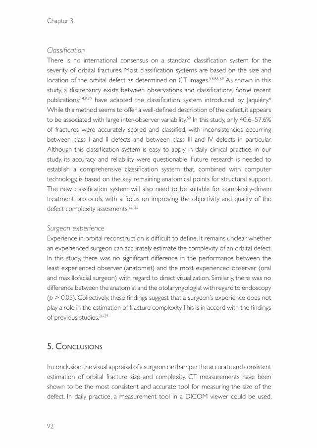
Chapter 3
92
ClassificationThere is no international consensus on a standard classification system for the severity of orbital fractures. Most classification systems are based on the size and location of the orbital defect as determined on CT images.5,6,66-69 As shown in this study, a discrepancy exists between observations and classifications. Some recent publications2-4,9,70 have adapted the classification system introduced by Jaquiéry.6 While this method seems to offer a well-defined description of the defect, it appears to be associated with large inter-observer variability.59 In this study, only 40.6–57.6% of fractures were accurately scored and classified, with inconsistencies occurring between class I and II defects and between class III and IV defects in particular. Although this classification system is easy to apply in daily clinical practice, in our study, its accuracy and reliability were questionable. Future research is needed to establish a comprehensive classification system that, combined with computer technology, is based on the key remaining anatomical points for structural support. The new classification system will also need to be suitable for complexity-driven treatment protocols, with a focus on improving the objectivity and quality of the defect complexity assesments.22, 23
Surgeon experienceExperience in orbital reconstruction is difficult to define. It remains unclear whether an experienced surgeon can accurately estimate the complexity of an orbital defect. In this study, there was no significant difference in the performance between the least experienced observer (anatomist) and the most experienced observer (oral and maxillofacial surgeon) with regard to direct visualization. Similarly, there was no difference between the anatomist and the otolaryngologist with regard to endoscopy (p > 0.05). Collectively, these findings suggest that a surgeon’s experience does not play a role in the estimation of fracture complexity. This is in accord with the findings of previous studies.26-29
5. cOnclusiOns
In conclusion, the visual appraisal of a surgeon can hamper the accurate and consistent estimation of orbital fracture size and complexity. CT measurements have been shown to be the most consistent and accurate tool for measuring the size of the defect. In daily practice, a measurement tool in a DICOM viewer could be used,
39372 Dubois, Leander.indd 92 04-03-16 10:19

Diagnostics
93
3
although software that allows manual adjustments of the axis are preferable. Our results show that direct intraoperative visualization and surgeon experience are of limited value in the estimation of fracture size and complexity and that endoscopy provides no significant additional advantages. Substantial overestimation of the size of critical defects may result in surgical overtreatment, which may in turn produce erroneous overestimation of the treatment outcome.
acknOwledgeMents
we thank Nick H.J. Lobé and Ludo Beenen from the Department of Radiology and Eric J. Lichtenberg from the Department of Anatomy, Embryology, and Physiology for their assistance in logistics and cadaver scanning. We also thank Floris Hartman for aiding in data collection and Arjen van Wijk for his advice on the statistical analysis.
39372 Dubois, Leander.indd 93 04-03-16 10:19

Chapter 3
94
References
1. Ewers R, Schicho K, Undt G, et al: Basic research and 12 years of clinical experience in computer-assisted navigation technology: a review. Int J Oral Maxillofac Surg 34:1, 2005
2. Dubois L, Steenen SA, Gooris PJ, et al: Controversies in orbital reconstruction—I. Defect-driven orbital reconstruction: a systematic review. Int J Oral Maxillofac Surg 44:308, 2015
3. Dubois L, Steenen SA, Gooris PJ, et al: Controversies in orbital reconstruction—II. Timing of post-traumatic orbital reconstruction: a systematic review. Int J Oral Maxillofac Surg 44:433, 2015
4. Dubois L, Steenen SA, Gooris PJ, et al: Controversies in orbital reconstruction—III. Biomaterials for orbital reconstruction: a review with clinical recommendations. Int J Oral Maxillofac Surg 2015 (in press)
5. Burnstine MA: Clinical recommendations for repair of isolated orbital floor fractures: an evidence-based analysis. Ophthalmology 109:1207, 2002
6. Jaquiéry C, Aeppli C, Cornelius P, et al: Reconstruction of orbital wall defects: critical review of 72 patients. Int J Oral Maxillofac Surg 36:193, 2007
7. Metzger MC, Hohlweg-Majert B, Schön R, et al: Verification of clinical precision after computer-aided reconstruction in craniomaxillofacial surgery. Oral Surg Oral Med Oral Pathol Oral Radiol Endod 104:e1, 2007
8. Wajih WA, Shaharuddin B, Razak NH: Hospital Universiti Sains Malaysia experience in orbital floor reconstruction: autogenous graft versus Medpor. J Oral Maxillofac Surg 69:1740, 2011
9. Kunz C, Sigron GR, Jaquiéry C: Functional outcome after non-surgical management of orbital fractures--the bias of decision-making according to size of defect: critical review of 48 patients. Br J Oral Maxillofac Surg 51:486, 2013
10. Bite U, Jackson IT, Forbes GS: Orbital volume measurements in enophthalmos using three-dimensional CT imaging. Plast Reconstr Surg 75:502, 1985
11. Manson PN, Grivas A, Rosenbaum A, et al: Studies on enophthalmos: II. The measurement of orbital injuries and their treatment by quantitative computed tomography. Plast Reconstr Surg 77:203, 1986
12. McGurk M, Whitehouse RW, Taylor PM, et al: Orbital volume measured by a low-dose CT scanning technique. Dentomaxillofac Radiol 21:70, 1992
13. Charteris DG, Chan CH, Whitehouse RW, et al: Orbital volume measurement in the management of pure blowout fractures of the orbital floor. Br J Ophthalmol 77:100, 1993
14. Harris GJ, Garcia GH, Logani SC, et al: Orbital blow-out fractures: correlation of preoperative computed tomography and postoperative ocular motility. Trans Am Ophthalmol Soc 96:329, 1998
15. Raskin EM, Millman AL, Lubkin V, et al: Prediction of late enophthalmos by volumetric analysis of orbital fractures. Ophthal Plast Reconstr Surg 14:19, 1998
16. Gunarajah DR, Samman N: Biomaterials for repair of orbital floor blowout fractures: a systematic review. J Oral Maxillofac Surg 71:550, 2013
17. Schramm A, Suarez-Cunqueiro MM, Rücker M, et al: Computer-assisted therapy in orbital and mid-facial reconstructions. Int J Med Robotics 5:111, 2009
18. Gander T, Essig H, Metzler P, et al: Patient specific implants (PSI) in reconstruction of orbital floor and wall fractures. J Craniomaxillofac Surg 43:126, 2015
19. Shah HA, Shipchandler TZ, Sufyan AS: Use of fracture size and soft tissue herniation on computed tomography to predict diplopia in isolated orbital floor fractures. Am J Otolaryngol 34:695, 2013
20. Lieger O, Schaller B, Zix J, et al: Repair of orbital floor fractures using bioresorbable poly-L/DL-lactide plates. Arch Facial Plast Surg 12:399, 2010
21. Dubois L, Jansen J, Schreurs R, et al: Predictability in orbital reconstruction: a human cadaver study. Part I: endoscopic-assisted orbital reconstruction. J Craniomaxillofac Surg 2015 (in press)
22. Dubois L, Schreurs R, Jansen J et al: Predictability in orbital reconstruction: a human cadaver study. Part II: navigation-assisted orbital reconstruction. J Craniomaxillofac Surg 2015 (in press)
23. Rana M, Chui CH, Wagner M, et al: Increasing the accuracy of orbital reconstruction with selective laser-melted patient-specific implants combined with intraoperative navigation. J Oral Maxillofac Surg 73:1113, 2015
39372 Dubois, Leander.indd 94 04-03-16 10:19
Diagnostics
95
3
24. O’Toole RV, Whitney A, Merchant N, et al: Variation in diagnosis of compartment syndrome by surgeons treating tibial shaft fractures. J Trauma 67:735, 2009
25. Komerik N, Muglali M, Tas B, et al: Difficulty of impacted mandibular third molar tooth removal: predictive ability of senior surgeons and residents. J Oral Maxillofac Surg 72:1062.e1, 2014
26. Leenders T, Vandevelde D, Mahieu G, et al: Reduction in variability of acetabular cup abduction using computer assisted surgery: a prospective and randomized study. Comput Aided Surg 7:99, 2002
27. Ganapathi M, Vendittoli PA, Lavigne M, et al: Femoral component positioning in hip resurfacing with and without navigation. Clin Orthop Relat Res 467:1341, 2009
28. Brin YS, Nikolaou VS, Joseph L, et al: Imageless computer assisted versus conventional total knee replacement. A Bayesian meta-analysis of 23 comparative studies. Int Orthop 35:331, 2011
29. Stiehler M, Goronzy J, Kirschner S, et al: Effect of surgical experience on imageless computer-assisted femoral component positioning in hip resurfacing—a preclinical study. Eur J Med Res 20:18, 2015
30. Kunz C, Audigé L, Cornelius CP, et al: The comprehensive AOCMF classification system: orbital fractures - level 3 tutorial. Craniomaxillofac Trauma Reconstr 7:S092, 2014
31. Moore CC, Bromwich M, Roth K, et al: Endoscopic anatomy of the orbital floor and maxillary sinus. J Craniofac Surg 19:271, 2008
32. Koo L, Hatton MP, Rubin PA: When is enophthalmos ‘significant’? Ophthal Plast Reconstr Surg 22:274, 2006
33. Park MS, Baek S: Measurement of fracture size using the picture archiving communication system in an outpatient clinic for factors that influence postoperative enophthalmos in adult inferior orbital wall fractures. J Craniofac Surg 24:1692, 2013
34. Goggin J, Jupiter DC, Czerwinski M: Simple computed tomography-based calculations of orbital floor fracture defect size are not sufficiently accurate for clinical use. J Oral Maxillofac Surg 73:112, 2015
35. Ploder O, Klug C, Backfrieder W, et al: 2D- and 3D-based measurements of orbital floor fractures from CT scans. J Craniomaxillofac Surg 30:153, 2002
36. Chen CT, Huang F, Chen YR: Management of posttraumatic enophthalmos. Chang Gung Med J 29:251, 2006
37. Marsh JL, Gado M: The longitudinal orbital CT projection: a versatile image for orbital assessment. Plast Reconstr Surg 71:308, 1983
38. Noda M, Noda K, Ideta S, et al: Repair of blowout orbital floor fracture by periosteal suturing. Clin Experiment Ophthalmol 39:364, 2011
39. Gellrich NC, Schramm A, Hammer B, et al: Computer-assisted secondary reconstruction of unilateral posttraumatic orbital deformity. Plast Reconstr Surg 110:1417, 2002
40. Heiland M, Habermann CR, Schmelzle R: Indications and limitations of intraoperative navigation in maxillofacial surgery. J Oral Maxillofac Surg 62:1059, 2004
41. Zhang Z, Zhang Y, He Y, et al: Correlation between volume of herniated orbital contents and the amount of enophthalmos in orbital floor and wall fractures. J Oral Maxillofac Surg 70:68, 2012
42. Parbhu KC, Galler KE, Li C, et al: Underestimation of soft tissue entrapment by computed tomography in orbital floor fractures in the pediatric population. Ophthalmology 115:1620, 2008
43. Giretzlehner M, Dirnberger J, Owen R, et al: The determination of total burn surface area: how big is the difference? Burns 40:170, 2014
44. Harish V, Raymond AP, Issler AC, et al: Accuracy of burn size estimation in patients transferred to adult Burn Units in Sydney, Australia: an audit of 698 patients. Burns 41:91, 2015
45. Strong EB, Kim KK, Diaz RC: Endoscopic approach to orbital blowout fracture repair. Otolaryngol Head Neck Surg 131:683, 2004
46. Polligkeit J, Grimm M, Peters JP, et al: Assessment of indications and clinical outcome for the endoscopy-assisted combined subciliary/transantral approach in treatment of complex orbital floor fractures. J Craniomaxillofac Surg 41:797, 2013
47. Margulies C, Krevsky B, Catalano MF: How accurate are endoscopic estimates of size? Gastrointest Endosc 40:174, 1994
48. Saunders CJ, Whetzel TP, Stokes RB, et al: Transantral endoscopic orbital floor exploration: a cadaver and clinical study. Plast Reconstr Surg 100:575, 1997
39372 Dubois, Leander.indd 95 04-03-16 10:19
Chapter 3
96
49. Kakibuchi M, Fukazawa K, Fukuda K, et al: Combination of transconjunctival and endonasal-transantral approach in the repair of blowout fractures involving the orbital floor. Br J Plast Surg 57:37, 2004.
50. Jin H-R, Yeon J-Y, Shin S-O, et al: Endoscopic versus external repair of orbital blowout fractures. Otolaryngol Head Neck Surg 136:38, 2007
51. Kwon JH, Kim JG, Moon JH, et al: Clinical analysis of surgical approaches for orbital floor fractures. Arch Facial Plast Surg 10:21, 2008
52. Balakrishnan K, Moe KS: Applications and outcomes of orbital and transorbital endoscopic surgery. Otolaryngol Head Neck Surg 144:815, 2011
53. Hundepool AC, Willemsen MA, Koudstaal MJ, et al: Open reduction versus endoscopically controlled reconstruction of orbital floor fractures: a retrospective analysis. Int J Oral Maxillofac Surg 41:489, 2012
54. Joseph JM, Glavas IP: Orbital fractures: a review. Clin Ophthalmol 5:95, 2011
55. Koornneef L: Current concepts on the management of orbital blow-out fractures. Ann Plast Surg 9:185, 1982
56. Gilbard SM, Mafee MF, Lagouros PA, et al: Orbital blowout fractures: the prognostic significance of computed tomography. Ophthalmology 92:1523, 1985
57. Biesman BS, Hornblass A, Lisman R, et al: Diplopia after surgical repair of orbital floor fractures. Ophthal Plast Reconstr Surg 12:9, 1996
58. Ploder O, Klug C, Voracek M, et al: A computer-based method for calculation of orbital floor fractures from coronal computed tomography scans. J Oral Maxillofac Surg 59:1437, 2001
59. Schouman T, Courvoisier DS, Imholz B, et al: Computational area measurement of orbital floor fractures: reliability, accuracy and rapidity. Eur J Radiol 81:2251, 2012
60. Christiansen EL, Thompson JR, Kopp S: Intra- and inter-observer variability and accuracy in the determination of linear and angular measurements in computed tomography. An in vitro and in situ study of human mandibles. Acta Odontol Scand 44:221, 1986
61. Ramieri G, Spada MC, Bianchi SD, et al: Dimensions and volumes of the orbit and orbital fat in posttraumatic enophthalmos. Dentomaxillofac Radiol 29:302, 2000
62. Grove Jr AS, Tadmor R, New PF, et al: Orbital fracture evaluation by coronal computed tomography. Am J Ophthalmol 85:679, 1978
63. Mathog RH: Management of orbital blow-out fractures. Otolaryngol Clin North Am 24:79, 1991
64. Beigi B, Khandwala M, Gupta D: Management of pure orbital floor fractures: a proposed protocol to prevent unnecessary or early surgery. Orbit 33:336, 2014
65. Schouman T, Scolozzi P: Simple CT-based calculations of orbital floor fracture defect size are not sufficiently accurate for clinical use. J Oral Maxillofac Surg 73:577, 2015
66. Baumann A, Ewers R: Use of the preseptal transconjunctival approach in orbit reconstruction surgery. J Oral Maxillofac Surg 59:287, 2001Schouman T, Courvoisier DS, Van Issum C, et al: Can systematic computed tomographic scan assessment predict treatment decision in pure orbital floor blowout fractures? J Oral Maxillofac Surg 70:1627, 2012
67. Wang HM, Huang CM, Zheng CH, et al: Tumor size as a prognostic factor in patients with advanced gastric cancer in the lower third of the stomach. World J Gastroenterol 18:5470, 2012
68. Hwang SH, Kim SW, Park CS, et al: Morphometric analysis of the infraorbital groove, canal, and foramen on three-dimensional reconstruction of computed tomography scans. Surg Radiol Anat 35:565, 2013
69. Lieger O, Schaller B, Kellner F, et al: Low-profile titanium mesh in the use of orbital reconstruction: a pilot study. Laryngoscope 122:982, 2012
70. Jansen J, Schreurs R, Dubois L, et al: Orbital volume analysis: validation of a semi-automatic software segmentation method. Int J Comput Assist Radiol Surg 2015 Jul 16 (Epub ahead of print)
39372 Dubois, Leander.indd 96 04-03-16 10:19

39372 Dubois, Leander.indd 97 04-03-16 10:19

39372 Dubois, Leander.indd 98 04-03-16 10:19

PREdICTABIlITY
39372 Dubois, Leander.indd 99 04-03-16 10:19

39372 Dubois, Leander.indd 100 04-03-16 10:19
CHAPTER 41
Orbital Implant Dislocation Frame
This chapter is an edited version of the manuscript: Schreurs R, Dubois L, Maal TJJ, Becking AG:
Measuring Predictability in Orbital Reconstruction: Quantitative Assessment of Orbital Implant Position – A Proof of Concept. PLoS ONE 2016:11: e0150162
39372 Dubois, Leander.indd 101 04-03-16 10:19

Chapter 41
102
intrOductiOn
The orbit is one of the most complex regions of the face in terms of reconstruction. Inaccurate restoration of orbital anatomy can result in functional dissimilarities and a poor aesthetical outcome. Unfortunately, sequellae of complex reconstructions are not rare.1,2 Recent technological developments, such as Computer Assisted Surgery (CAS), have been proven to improve the safety and outcome of existing surgical procedures.3
The use of the Computed Tomography scans for orbital reconstructive surgery has extended beyond diagnostic imaging alone.3 By using advanced diagnostics software modalities such as iPlan (version 3.0.5; Brainlab®, Feldkirchen, Germany), the ideal location of the predefined implant, either preformed or patient-specific, can be assessed preoperatively. In navigation assisted surgery, the preoperative planning can be translated to the intraoperative setting and can provide the surgeon a guide map to the predetermined ideal implant location. The use of preoperative planning in combination with intraoperative navigation to aid the surgeon in reaching optimal surgical outcome is encapsulated in the surgical concept of CAS.
In orbital reconstructive surgery, CAS provides the surgeon with a target location of the preformed implant, thought to provide the best possible anatomical reconstruction of the affected orbit. Through imaging of the acquired position either intraoperatively or postoperatively, objective assessment of the surgical result in comparison to the target result is possible. In literature, various methods have been described to quantify implant location in patients, from linear measurements on individual CT slices to color-coded distance maps;4-15 the mirrored orbit is most often chosen as the target surface, to which measurements of implant location are related.4,6-13 However, in order to be able to objectively assess surgical accuracy, patient dependency should be excluded from the measurements. Moreover, local measurements on either one or multiple planar views alone will not be able to provide accurate information about locational as well as translational dislocation of the implant to the surgeon, A clinical example is provided in Fig. 1. Distance measurements on the coronal and sagittal slices visualized would yield small differences, some of which could be related to differences in the anatomical shape of the orbit in the patient in relation to the shape of the preformed implant. Overall, a good implant position seems to have been acquired. Only when the acquired
39372 Dubois, Leander.indd 102 04-03-16 10:19
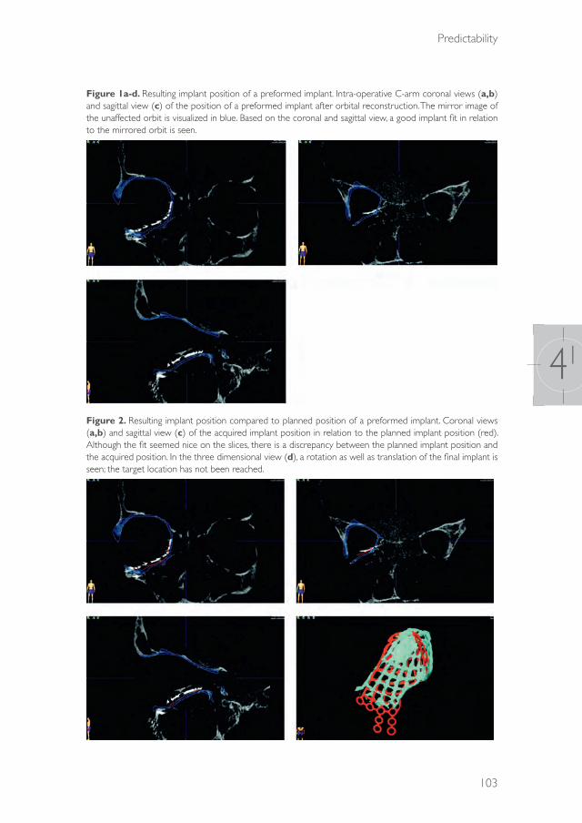
Predictability
103
41
Figure 1a-d. Resulting implant position of a preformed implant. Intra-operative C-arm coronal views (a,b) and sagittal view (c) of the position of a preformed implant after orbital reconstruction. The mirror image of the unaffected orbit is visualized in blue. Based on the coronal and sagittal view, a good implant fit in relation to the mirrored orbit is seen.
Figure 2. Resulting implant position compared to planned position of a preformed implant. Coronal views (a,b) and sagittal view (c) of the acquired implant position in relation to the planned implant position (red). Although the fit seemed nice on the slices, there is a discrepancy between the planned implant position and the acquired position. In the three dimensional view (d), a rotation as well as translation of the final implant is seen; the target location has not been reached.
39372 Dubois, Leander.indd 103 04-03-16 10:19
Chapter 41
104
position is visualized in relation to the planned implant, the deviation from the optimal position (rotation and translation) from the planned implant position becomes apparent (Fig. 2). This information can be helpful for the surgeon evaluating his/her post-operative results.
Since a target location is already provided in CAS, the actual implant location should be related to the planned implant location. The shape of the preformed orbital implant is known; therefore, when a reference frame is created, rotational as well as translational deviations can be quantified, providing a ‘true’ three-dimensional evaluation of implant position. Moreover, measures of rotation and translation can provide direct feedback to the surgeon on the adjustments which are necessary to obtain the ideal implant location. Patient dependency is eradicated from the equation, making comparison between patients and even populations reconstructed with the same preformed implant possible. This study presents a largely automated dislocation measurement method by means of a reference frame for the newly designed KLS preformed Orbital Implant (KLS Martin, Tuttlingen, Germany); this will hereafter be referred to as the Orbital Implant Dislocation Frame (OIDF).
MethOds
Reference frameThe Orbital Implant Dislocation Frame is visualized in Fig. 3. The coordinate frame of the implant was designed bearing the principal axes of aircraft dynamics in mind.16 The origin was pinpointed on the reinforced triangular part of the implant floor, intersected by both the longest axis of the maze and the most proximal contralateral bridges of the maze. The x-axis runs parallel to the longest axis to the tip of the implant, whereas the y-axis intersects the most proximal contralateral extensions; the perpendicular z-axis faces upwards. The rotations, expressed in pitch, yaw and roll, are also visualized in Fig. 3.
Human specimen studyComputer assisted orbital reconstructive surgery with a preformed titanium mesh plate was performed by LD on 3 human specimen heads with intact orbits, fixed in 2.4% formaldehyde. The specimen heads were supplied by the department of Anatomy of the Academic Medical Centre (AMC). Following the Jaquiéry classification,17,18
39372 Dubois, Leander.indd 104 04-03-16 10:19

Predictability
105
41
complex orbital defects (Class III-IV) were created with Piezo surgery. CT scans (Sensation 64, Siemens Medical Solutions, Forchheim, Germany) of the human specimen heads were acquired at baseline (with intact orbits, t0), after creation of the orbital defects (t1) and postoperatively after implant placement (t2). The standard CT head trauma protocol was used (collimation 20 * 0.6 mm, with 120 kV, 350 mAs, pitch 0.85, FOV 30 cm, matrix size 512 * 512, reconstruction slice thickness 0.75 mm with overlapping increment 0.4 mm, in bone kernel H70s and bone window W1600 L400). The proposed method of measuring implant dislocation described below was tested on the human specimen heads, in order to test the dislocation measurement and demonstrate its feasibility.
Figure 3. Orbital Implant Dislocation Frame. The orientation of the axes, as well as the rotations around the axes are visualized. For the right-sided implant, the y-axis is flipped in order to be able to compare left and right sided implants. As a consequence of flipping the y-axis, the yaw and roll direction are also opposed.
PlanningThe t0 and t1 scans were fused using iPlan software; a 3D stereolithographic model (stl) of the preformed orbital implant was also imported in the dataset. The stl of the preformed implant was positioned at the ideal location for anatomical
39372 Dubois, Leander.indd 105 04-03-16 10:19

Chapter 41
106
reconstruction, based on information about the unaffected orbital contour (t0 scan). However, information about existing bony ledges of the affected orbit (t1 scan), which is needed for adequate positioning of the implant, was also taken into account in finding the optimal fit. Consensus on the optimal implant position was reached between observers RS and LD for all planned implants.
SegmentationAfter the postoperative (t2) scan was acquired, the t0 and t2 scans were registered with the use of the Image Fusion modality in iPlan. A threshold-based segmentation with threshold ≥1200 HU was generated to segment the implant in the registered t2 scan; afterwards, post-processing of the segmentation result was performed by RS to remove superfluously segmented bony tissue. Care was taken not to include the three screw rings extending proximally from the implant, since these could have been adjusted during the surgical procedure; these bended areas of the implant could hamper surface registration between planned implant and the surgically positioned one. The fixation screw was also removed from the segmentation result.
Implant placement evaluation The planned implant was exported as an stl model (M0) from the iPlan software; the segmentation result was also exported in stl format (M2). The local coordinate frame of the planned implant was transformed to the global reference frame by matching the planned implant on the reference implant, with an Iterative Closest Point approach:19
M0,G = TL→ GM0 (1)
The same transformation (TL→ G) was applied to the segmented implant, thereby maintaining the relative orientation between M0 and M2, but transforming them both to the global coordinate frame: M2,G = TL→ GM2 (2)
The ICP algorithm was also utilized to register the planned (M0,G) implant on the resulting (M2,G) implant, in order to determine the transformation matrix between the planned and acquired implant position: M2,G = T0→2Mo,G (3)
39372 Dubois, Leander.indd 106 04-03-16 10:19

Predictability
107
41
From the resulting transformation matrix T0→2 , the rotation parameters pitch (rotation around y-axis, β), yaw (rotation around z-axis, α) and roll (rotation around x-axis, γ) were calculated using the following formula:
Implant placement evaluation
The planned implant was exported as an stl model (𝑀𝑀!) from the iPlan software; the segmentation
result was also exported in stl format (𝑀𝑀!). The local coordinate frame of the planned implant was
transformed to the global reference frame by matching the planned implant on the reference
implant, with an Iterative Closest Point approach:19
𝑀𝑀!,! = T!→!𝑀𝑀!
(1)
The same transformation (T!→!) was applied to the segmented implant, thereby maintaining the
relative orientation between M0 and M2, but transforming them both to the global coordinate frame:
𝑀𝑀!,! = T!→!𝑀𝑀!
(2)
The ICP algorithm was also utilized to register the planned (𝑀𝑀!,!) implant on the resulting (𝑀𝑀!,!)
implant, in order to determine the transformation matrix between the planned and acquired implant
position:
𝑀𝑀!,! = T!→!𝑀𝑀!,!
(3)
From the resulting transformation matrix T!→!, the rotation parameters pitch (rotation around y-‐
axis, β), yaw (rotation around z-‐axis, α) and roll (rotation around x-‐axis, γ) were calculated using the
following formula:
𝑅𝑅!→! 𝛼𝛼,𝛽𝛽, 𝛾𝛾 = 𝑅𝑅! 𝛼𝛼 𝑅𝑅! 𝛽𝛽 𝑅𝑅! 𝛾𝛾
=cos𝛼𝛼 cos𝛽𝛽 cos𝛼𝛼 sin𝛽𝛽 sin 𝛾𝛾 − sin 𝛼𝛼 cos 𝛾𝛾 cos𝛼𝛼 sin𝛽𝛽 cos 𝛾𝛾 + sin 𝛼𝛼 sin 𝛾𝛾sin𝛼𝛼 cos𝛽𝛽 sin𝛼𝛼 sin𝛽𝛽 sin 𝛾𝛾 + cos𝛼𝛼 cos 𝛾𝛾 sin 𝛼𝛼 sin𝛽𝛽 cos 𝛾𝛾−cos𝛼𝛼 sin 𝛾𝛾− sin𝛽𝛽 cos𝛽𝛽 sin 𝛾𝛾 cos𝛽𝛽 cos 𝛾𝛾
(4) (4)
The order of rotations in the resulting calculation is, by definition of the formula above, regarded as roll first, pitch second, and yaw third (respectively rotations around x-axis, around y-axis, around z-axis). The translational parameters of the origin in all three directions were also acquired from the transformation matrix T0→ 2. Since transformation of the complete implant is described by the transformation matrix, the translation of other key points on the implant (superiormost point on medial ledge, dorsal tip of implant) can be calculated if desirable. These points are also indicated in Fig. 3. Since all planned implants are registered on the reference implant, rotations and translations can be compared for all surgical interventions. For the right-sided implant, the reference frame was mirrored over the xz-plane, in order to be able to compare results for left-sided and right-sided orbital reconstructions.
results
Specimen 1In Fig. 4, the planned implant position and segmentation of the resulting implant position are visualized in red and green respectively, in both coronal (a,b) and sagittal view (c) of the baseline (t0) scan. In both coronal views shown here, as well as the sagittal view, comparison to the implant floor would suggest an adequate position of the resulting implant. In Fig. 4b the lateral extension of the implant is positioned too far laterally, but overall the contour is nicely followed in these slices. A 3D view can be generated after the segmentation process described above; when the 3D view is taken into account, the resulting implant position turns out to significantly deviate from the planned implant position. Analysis with the method described above yields the following dislocation parameters: roll -9.3°, pitch -0.4°, yaw 11.3°,
39372 Dubois, Leander.indd 107 04-03-16 10:19
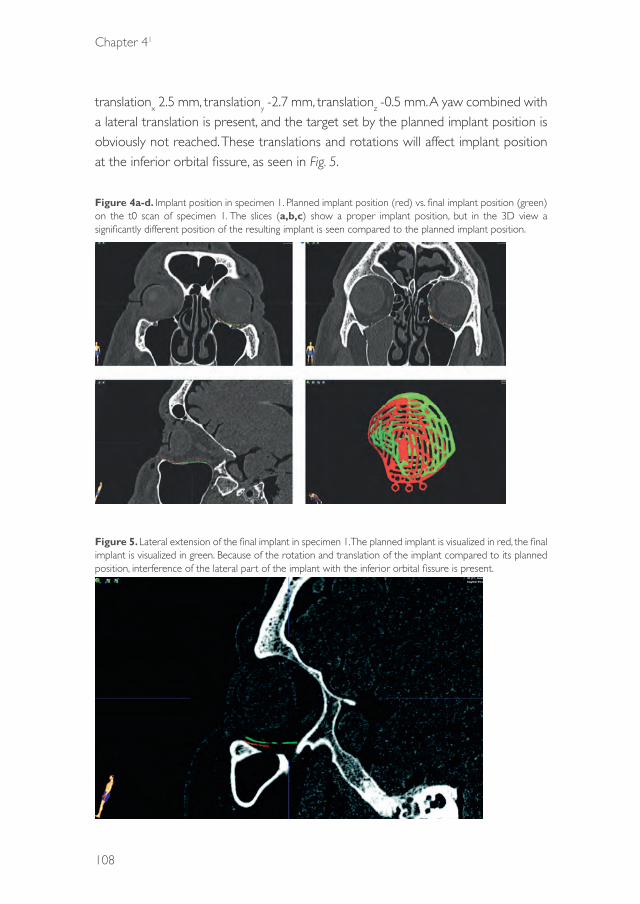
Chapter 41
108
translationx 2.5 mm, translationy -2.7 mm, translationz -0.5 mm. A yaw combined with a lateral translation is present, and the target set by the planned implant position is obviously not reached. These translations and rotations will affect implant position at the inferior orbital fissure, as seen in Fig. 5.
Figure 4a-d. Implant position in specimen 1. Planned implant position (red) vs. final implant position (green) on the t0 scan of specimen 1. The slices (a,b,c) show a proper implant position, but in the 3D view a significantly different position of the resulting implant is seen compared to the planned implant position.
Figure 5. Lateral extension of the final implant in specimen 1. The planned implant is visualized in red, the final implant is visualized in green. Because of the rotation and translation of the implant compared to its planned position, interference of the lateral part of the implant with the inferior orbital fissure is present.
39372 Dubois, Leander.indd 108 04-03-16 10:19

Predictability
109
41
Specimen 2Fig. 6 visualizes the implant placement in specimen 2. In the coronal slices, the orbital contour is nicely followed medially; laterally, there is a significant deviation between implant position and orbital floor. From the sagittal view it could be concluded that the implant is placed too far dorsal. In the coronal views, the cross-section through the resulting implant would be visualized at another level than the cross-section through the planned implant. This may explain why there seems to be overlap between planned and resulting implant medially, but a deviation laterally. The three dimensional view, generated after segmentation, shows that a dorsal translation of the resulting implant is not the only translational error compared to the planned position; a lateral displacement is also present. Analysis with the Orbital Implant Dislocation Frame shows that there are also a roll rotation in the resulting implant (roll -11.2°, pitch -5.3°, yaw 0.1°, translationx 4.1 mm, translationy -2.9 mm, translationz -0.1 mm); although this could not be concluded from the individual slices, it is clearly shown in the 3D view in Fig. 7.
Figure 6a-d. Implant position in specimen 2. Planned implant position (red) vs. final implant position (green) on the t0 scan of specimen 2. Based on the sagittal slice, a dorsal translation is present in the final implant position. The 3D view reveals that the implant is also translated laterally, this cannot be identified on the coronal and sagittal views alone.
39372 Dubois, Leander.indd 109 04-03-16 10:19
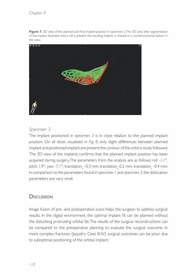
Chapter 41
110
Figure 7. 3D view of the planned and final implant position in specimen 2. The 3D view after segmentation of the implant illustrates that a roll is present: the resulting implant is rotated in a counterclockwise fashion in this view.
Specimen 3The implant positioned in specimen 3 is in close relation to the planned implant position. On all slices visualized in Fig. 8, only slight differences between planned implant and positioned implant are present; the contour of the orbit is nicely followed. The 3D view of the implants confirms that the planned implant position has been acquired during surgery. The parameters from the analysis are as follows: roll -1.1°, pitch 1.9°, yaw -7.1°, translationx -0.3 mm, translationy 0.2 mm, translationz -0.4 mm. In comparison to the parameters found in specimen 1 and specimen 2, the dislocation parameters are very small.
discussiOn
Image fusion of pre- and postoperative scans helps the surgeon to address surgical results. In the digital environment, the optimal implant fit can be planned without the disturbing protruding orbital fat. The results of the surgical reconstructions can be compared to the preoperative planning to evaluate the surgical outcome. In more complex fractures (Jaquiéry Class III-IV) surgical outcomes can be poor due to suboptimal positioning of the orbital implant.1
39372 Dubois, Leander.indd 110 04-03-16 10:19

Predictability
111
41
Figure 8a-d. Implant position in specimen 3. Planned implant position (red) vs. final implant position (green) on the t0 scan of specimen 3. The relation of the final implant with both the planned implant and the orbital contour seems excellent; the 3D view shows the surgical target has indeed been reached, although a minor yaw seems to be present.
Andrades et al.20 showed no direct correlation between implant position, orbital volume and clinical outcome. Clinical parameters in globe position as enopthalmos and hypoglobus are influenced by both orbital volume and the shape of the orbital walls. , The first and most controllable step in reconstructive surgery should be to create the optimal anatomically shaped orbit and, most importantly, offer patients a predictable result.1 Therefore, reaching the planning set by the preoperative planning should be the goal for predictably carrying out orbital reconstructive surgery.
CAS becomes target surgery, so the evaluation of planned vs acquired result is an essential step to benefit from these technological advantages.The goal of implant placement is to recontour the bony orbit or restoring the orbital volume and improve ocular movements.
Patient-specific implants (PSI) are perfectly shaped, and have the most potential for optimal restoration of the contour as well as volume of the fractured orbit. However, cost and limited availability through logistic factors pose serious drawbacks on the use of PSI meshes for orbital reconstruction. In complex defects (Class III-VI) contour becomes a more important factor for repositioning the globe in a proper
39372 Dubois, Leander.indd 111 04-03-16 10:19
Chapter 41
112
position.1,17 Various studies have shown the potential of preformed implants mesh as an easily usable and cost-effective alternative to PSI’s for true-to-original orbital reconstruction.4,9,20 The predefined shape makes the implant perfectly suitable for the concept of CAS, where the optimal implant position in relation to desired orbital contour can be planned beforehand. A novel method for standardized position analysis of the acquired implant position has been described in this article in a specimen study; it would be interesting to relate the position parameters to clinical outcome measures such as acquired globe position and orbital volume in prospective patient cohort. .
In this study, a reference frame for a preformed implant was designed, and rotation and translation between planned position and segmented implant in the matched postoperative scan were calculated. In literature, various methods exist to assess implant position after surgery. Linear measurements between mirrored (unaffected) orbit and the positioned implant, on either one slice of the postoperative CT scan4,5 or multiple slices,6,7,11 are frequently reported as a measure of obtained implant location in comparison to the ideal location. These measurements are reported to be hampered by the assumption of symmetry between affected and unaffected orbit and error originating from the measurement points chosen.21 A difference between unaffected parts of the affected orbital floor and the mirrored unaffected orbit are visualized in Fig. 9. If linear measurements were to be performed in these examples, the difference in symmetry would affect the measurement of implant dislocation. Other factors affecting accuracy of linear measurements are scan-related obstructions, such as slice thickness and implant scatter, and the acquired location after mirroring of the unaffected orbit. A different position of the midsagittal plane will lead to a different location of the mirrored object on the affected side and therefore quantification of implant placement could yield different results if performed by different observers.
If 3D shape analysis through (color-coded) distance maps for the complete implant is used,8,12,13, errors originating from the selection of the measurement points are eradicated. However, distance measurements to the mirrored orbital floor impose another problem on implant placement evaluation: whilst important to patient outcome, the variations in patients’ orbital floor shapes influence the outcome of the measurements. Moreover, the method is unusable in patients with bilateral orbital fractures (i.e. patients with Le Fort II/III or NOE fractures). The goal of this study
39372 Dubois, Leander.indd 112 04-03-16 10:19

Predictability
113
41
was to quantify implant placement in a way that respective comparisons between different methods, surgeons and patients becomes possible: the planned location served as the reference for surgical outcome evaluation.
Figure 9ab. Differences in orbital symmetry. The mirror image of the unaffected orbit is visualized in blue. Distances were measured between unaffected bony parts of the affected orbit and the mirrored orbit. If the mirrored orbit would be used as a reference for implant position, the measurement in (a) would yield negative values at the posterior ledge; the difference in symmetry measured in (b) would add up to the dislocation measurement, since the implant would always be positioned cranial to existing bony structures.
Stoor et al.15 did choose the planned implant as the reference, and calculated the volumetric overlap between the planned implant and a segmentation of the acquired implant position. This volumetric overlap measure, as well as the aforementioned distance measurements provide only limited insight in the parameters which are responsible for implant malposition. Although the measurements proposed by Stoor et al. will be affected by rotational as well as translational displacement errors, it is not possible to separately assess these parameters. The innovative method proposed for preformed implants in this article has three major advantages over traditional measurement methods: first, it provides individual measures for all degrees of freedom in implant dislocation; all possible sources of error in the obtained position can be distinguished and quantified. Secondly, the measurements are largely automatic and therefore robust. Segmentation combined with automatic registration prevents emergence of observer-related errors and/or variability. Lastly, since the implant position is only assessed in comparison to the planned (and oriented) preformed stl, outcomes between patients and observers can be compared for all variables. An additional advantage of this method of assessment is that the possible inaccuracies arising from the mirroring process are abolished.
A disadvantage of the proposed method may be the influence of bending of the implant during surgery. By definition, the ICP algorithm will search for the best possible match between the surfaces; the accuracy of the match on an intraoperatively
39372 Dubois, Leander.indd 113 04-03-16 10:19

Chapter 41
114
bended implant will be hampered by its change in shape in relation to the planned implant. The concept of preformed implants ideally should make bending of the implant obsolete. Moreover, registration on a partial surface of the implant is also possible, so to exclude the bended areas and provide the best possible match on the region of interest of the implant.
Another drawback of the method could be in the choice of the reference axes. Care has been taken to aim for the most logical and intuitive design for the reference frame. Choosing a different orientation of the reference frame would result in differences in the results. It is strongly suggested that the same Orbital Implant Dislocation Frame will be used for a preformed implant to be able to compare surgical outcome between different surgeons, methods and studies. Indication of one or multiple axes on the stl of the implant to indicate the location of the reference frame, as well as making the reference implant used in this study available, could aid in increasing comparability of studies.
Since the proposed OIDF quantifies and visualizes all parameters involved in dislocation, it may be an excellent method of feedback to the surgeon intraoperatively. If intraoperative imaging is performed and combined with 3D visualization, this method will be able to provide real-time quantitative feedback on the differences between the planned and the actual position of the implant. This enables the surgeon to correct the errors within the surgical session. In postoperative imaging, the analysis method will aid in post-operative evaluation and choices for re-operations in patients with suboptimal clinical outcomes.
cOnclusiOn
This study proposes a novel method of quantifying the outcome of orbital reconstructive surgery. All parameters influencing implant location are quantified, and at the same time the observer-related and patient-related factors are eradicated from the results. Clinically, this method is able to compare different surgical methods for predictability of the reconstruction, provide direct feedback intraoperatively and provide more thorough information about implant dislocation to the surgeon postoperatively. It is also holds a valuable scientific possibility to compare the results in case-series and multi-center observations.
39372 Dubois, Leander.indd 114 04-03-16 10:19
Predictability
115
41
acknOwledgeMents
The authors would like to thank KLS for providing the preformed implants, Petra Habets and Eric Lichtenberg of the department of Anatomy and Ludo Beenen of the department of Radiology for their assistance and support in the specimen study.
39372 Dubois, Leander.indd 115 04-03-16 10:19
Chapter 41
116
references
1. Dubois L, Steenen SA, Gooris PJJ, Mourits MP, Becking AG. Controversies in orbital reconstruction-I. Defect-driven orbital reconstruction: a systematic review. Int J Oral Maxillofac Surg. 2014: 44: 308–15.
2. Bell RB, Markiewicz MR. Computer-assisted planning, stereolithographic modeling, and intraoperative navigation for complex orbital reconstruction: a descriptive study in a preliminary cohort. J Oral Maxillofac Surg. 2009: 67: 2559–70.
3. Dubois L, Steenen SA, Gooris PJJ, Mourits MP, Becking AG. Controversies in orbital reconstruction-II. Timing of post-traumatic orbital reconstruction: a systematic review. Int J Oral Maxillofac Surg. 2015: 44: 433-40.
4. Cai EZ, Koh YP, Hing ECH, Low JR, Shen JY, Wong HC, et al. Computer-assisted navigational surgery improves outcomes in orbital reconstructive surgery. J Craniofac Surg. 2012: 23: 1567–73.
5. Strong EB, Fuller SC, Wiley DF, Zumbansen J, Wilson MD, Metzger MC. Preformed vs intraoperative bending of titanium mesh for orbital reconstruction. Otolaryngol Head Neck Surg. 2013: 149: 60–6.
6. Novelli G, Tonellini G, Mazzoleni F, Bozzetti A, Sozzi D. Virtual surgery simulation in orbital wall reconstruction: integration of surgical navigation and stereolithographic models. J Craniomaxillofac Surg. 2014: 42: 2025–34.
7. Metzger MC, Schön R, Weyer N, Rafii A, Gellrich N-C, Schmelzeisen R, et al. Anatomical 3 dimensional pre-bent titanium implant for orbital floor fractures. Ophthalmology. 2006: 113: 1863–8.
8. Metzger MC, Hohlweg-Majert B, Schön R, Teschner M, Gellrich N-C, Schmelzeisen R, et al. Verification of clinical precision after computer-aided reconstruction in craniomaxillofacial surgery. Oral Surg Oral Med Oral Pathol Oral Radiol Endod. 2007: 104: 1–10.
9. Metzger MC, Schön R, Schulze D, Carvalho C, Gutwald R, Schmelzeisen R. Individual preformed titanium meshes for orbital fractures. Oral Surg Oral Med Oral Pathol Oral Radiol Endod. 2006: 102: 442–7.
10. Schön R, Metzger MC, Zizelmann C, Weyer N, Schmelzeisen R. Individually preformed titanium mesh implants for a true-to-original repair of orbital fractures. Int J Oral Maxillofac Surg. 2006: 35: 990–5.
11. Zizelmann C, Gellrich NC, Metzger MC, Schoen R, Schmelzeisen R, Schramm A. Computer-assisted reconstruction of orbital floor based on cone beam tomography. Br J Oral Maxillofac Surg. 2007: 45: 79–80.
12. Essig H, Dressel L, Rana M, Rana M, Kokemueller H, Ruecker M, et al. Precision of posttraumatic primary orbital reconstruction using individually bent titanium mesh with and without navigation: a retrospective study. Head Face Med. 2013: 9: 18.
13. Gander T, Essig H, Metzler P, Lindhorst D, Dubois L, Rücker M, et al. Patient specific implants (PSI) in reconstruction of orbital floor and wall fractures. J Craniomaxillofac Surg. 2015: 43: 126–30.
14. Ellis E, Tan Y. Assessment of internal orbital reconstructions for pure blowout fractures: cranial bone grafts versus titanium mesh. J Oral Maxillofac Surg. 2003: 61: 442–53.
15. Stoor P, Suomalainen A, Lindqvist C, Mesimäki K, Danielsson D, Westermark A, et al. Rapid prototyped patient specific implants for reconstruction of orbital wall defects. J Craniomaxillofac Surg. 2014: 42: 1644–9.
16. Verhamme LM, Meijer GJ, Bergé SJ, Soehardi RA, Xi T, de Haan AFJ, et al. An accuracy study of computer-planned implant placement in the augmented maxilla using mucosa-supported surgical templates. Clin Implant Dent Relat Res. 2014: 17: 343-52.
17. Jaquiéry C, Aeppli C, Cornelius P, Palmowsky A, Kunz C, Hammer B. Reconstruction of orbital wall defects: critical review of 72 patients. Int J Oral Maxillofac Surg. 2007;36:193–9.
18. Kunz C, Sigron GR, Jaquiéry C. Functional outcome after non-surgical management of orbital fractures – the bias of decision-making according to size of defect: critical review of 48 patients. Br J Oral Maxillofac Surg. 2013: 51: 486–92.
19. Besl PJ, McKay ND. A method for registration of 3-D shapes. Pattern Anal Mach Intell IEEE Trans. 1992: 14: 239–56.
20. Andrades P, Hernandez D, Falguera MI, Millan JM, Heredero S, Gutierrez R, et al. Degrees of tolerance in post-traumatic orbital volume correction: the role of prefabricated mesh. J Oral Maxillofac Surg. 2009: 67: 2404–11.
21. Fuller SC, Strong EB. Computer applications in facial plastic and reconstructive surgery. Curr Opin Otolaryngol Head Neck Surg. 2007: 15: 233–7.
39372 Dubois, Leander.indd 116 04-03-16 10:19

39372 Dubois, Leander.indd 117 04-03-16 10:19

39372 Dubois, Leander.indd 118 04-03-16 10:19

CHAPTER 42
Endoscopic assisted orbital reconstruction
This chapter is an edited version of the manuscript: Dubois L, Jansen J, Schreurs R, Saeed P, Beenen, L, Gooris PJJ, Maal TJJ, Becking AG:
Predictability in orbital reconstruction: A human cadaver study, part I: Endoscopic-assisted orbital reconstruction. J Craniomaxillofac Surg. 2015: 43: 2034-41.
39372 Dubois, Leander.indd 119 04-03-16 10:19

Chapter 42
120
1. intrOductiOn
Complex orbital fractures may cause functional and cosmetic post-traumatic impairment. Adequate reconstruction is crucial for a satisfactory surgical outcome, although it is difficult to achieve.1 The complexity of orbital fracture repair is well documented.2 These fractures are associated with less accurate reconstruction because of the potential for suboptimal implant placement, which may result in disabling enophthalmos and diplopia.3 From a surgical perspective, the most complex orbital fractures are characterized by large defects accompanied by loss of majority of the orbital structures in the floor and medial wall regions. For the reconstruction of large defects, an additional visualization tool may be beneficial. Intra-operative endoscopy may be a well available and less expensive alternative for image-guided navigation or intra-operative imaging. The availability of these modalities are limited to a few well-equipped centres.4-7
For the surgical repair of complex orbital fractures, most surgeons choose the conventional transcutaneous or transconjunctival approach, which allows proper visualization of the defect size and location.8 The goal of reconstruction is to restore function and aesthetics by recontouring the bony orbit to its anatomical shape. However, visualization may be difficult during repositioning of the prolapsed orbital tissue from the sinuses into the orbit and during recontouring of the walls during placement of the orbital implant. Small errors in orbital floor implant positioning can cause both functional and cosmetic complications.9,10 One of the most common reasons for inaccurate implant placement is the inability to accurately define the posterior orbital ledge, which is formed by the orbital process of the palatine bone and extends as part of the orbital floor at the transition zone from the inferior orbital fissure to the superior orbital fissure. Implant placement on this ledge is important to ensure posterior support, although it can be challenging. The ledge must be cleared of all soft tissue, while the adjacent orbital fat and optic nerve must remain undisturbed.11
Transantral endoscopic surgical repair for orbital floor fractures has gained popularity in recent years.12-17 In 1950, Converse et al.18 described a technique for palpation of the orbital floor through the maxillary sinus before conversion to transorbital exploration. Walter19 later used the transmaxillary pathway to visualize
39372 Dubois, Leander.indd 120 04-03-16 10:19
Predictability
121
42
and repair orbital floor fractures. Because the maxillary sinus provides a confined surgical space, endoscopic management of orbital floor fractures is technically the easiest. Trans-sinusoidal endoscopy reportedly offers excellent visualization and allows confirmation of secure and accurate implant placement.20
Strong20 advocated that the indications for endoscopic repair are identical to those for conventional repair. Other studies showed that the predictable, completely endoscopic repair of orbital fractures is limited to trapdoor fractures, with the placement of no or small implants.11,21 Even with these limited therapeutic indications, up to 15% of intended endoscopic approaches to the orbit are converted to an open approach.22 In patients with large orbital defects involving the medial wall and floor, the transorbital approach is mandatory for clear exposure and placement of solid implant material. Therefore, a combined endoscopic and transorbital approach was suggested to enable dual examination and manipulation of the orbital implant by the surgeon, with the goal of improving the outcome of surgical repair of orbital floor fractures.11,14,23 A previous study suggested that this combined approach minimizes the risk of inaccurate implant positioning.24 The potential major complications of endoscopic orbital floor repair are similar to those of the open approach, including blindness, persistent diplopia or residual enophthalmos. Unfortunately, none of the previous studies employed a well-defined classification scheme for orbital fractures, and all were retrospective in nature.11,12,14,15,23,24 In addition, most studies lacked a control group,11,23,24 included small patient samples (4–48 patients) and used different reconstruction materials.
The aim of this study was to assess the benefits of endoscopic-assisted reconstruction (EAR) for ideal implant positioning in patients with standardized complex orbital defects (Class III–IV). Specifically, the accuracy of implant positioning was compared between conventional transconjunctival reconstruction (TCR) and EAR in human cadaveric models.
39372 Dubois, Leander.indd 121 04-03-16 10:19
Chapter 42
122
2. Materials and MethOds
MaterialsTen human cadaveric heads (20 orbits) were obtained from the Department of Anatomy of the Academic Medical Hospital, the University of Amsterdam. Of the 20 orbits, one was excluded because of sinus pathology (osteoma). Eventually, 19 orbits were included in this study.
The orbital floor and medial wall were fully exposed through a standard transconjunctival incision, and complex orbital defects (Class III–IV) were created by Piezo surgery according to the Jaquiéry classification.25,26 A gingivobuccal incision was placed, and a 5-mm antrostomy was created by piezosurgery (Mectron, Carasco, Italy) in the concavity of the canine fossa to facilitate endoscopic inspection. The sinus mucosa was removed to facilitate inspection of the defect contours. The cadaveric heads were subjected to computed tomography (CT; Sensation 64, Siemens Medical Solutions, Forchheim, Germany) at baseline (with intact orbits, T0), after creation of the orbital defects (T1) and after implant placement (T2). The scanning parameters were as follows: collimation, 20 × 0.6 mm; 120 kV; 350 mAs; pitch, 0.85; field of view, 30 cm; matrix, 512 × 512; reconstruction slice thickness, 0.75 mm with 0.4-mm overlapping increments; bone kernel, H70s; and bone window, W1600 L400.
Validation studyThe consistency of reconstruction was first assessed in a validation study. Two oral and maxillofacial surgeons (LD and PG), both experienced in orbital reconstruction, performed the surgeries on each human specimen using either a solitary transconjunctival or a combined (transconjuctival and endoscopic) approach. Preformed orbital titanium mesh plates (KLS Martin, Tuttlingen, Germany) were used. The drill holes were covered and camouflaged between the two sessions by filling with DuraLay (Reliance Dental Mfg. Co, Worth, IL, USA). Each orbit was reconstructed and scanned six times in total. Inter- and intra-surgeon variability was determined using the inter-class correlation coefficient (ICC).
MethodsIn the first surgical session, all orbits (n = 19) were reconstructed by one surgeon (LD) through the conventional transconjunctival approach. Reconstruction was performed again in a second session using a combined transconjunctival and
39372 Dubois, Leander.indd 122 04-03-16 10:19

Predictability
123
42
transantral endoscopic approach by the same surgeon. A 30° endoscope (Storz, Tuttlingen, Germany) was placed by the assisting surgeon (JJ), and orbital prolapse was reduced using the transconjunctival approach. Reduction of the orbital prolapse was visualized both transconjunctivally and endoscopically. The implant was placed in a presumably adequate position, and the placement was verified using a bidirectional view. The implants were fixed with a single bone screw, and the specimens were scanned according to protocol. After scanning, the implants were removed and the drill holes were covered and camouflaged by filling with DuraLay (Reliance Dental Mfg. Co). The surgeons completed a questionnaire about their perception of the predictability and quality of the reconstruction. For consistency in measurements, one surgeon (LD) performed the reconstructions twice in both groups.
Contour analysisThe quality of the reconstructions was assessed using iPlan software (version 3.0.5, BrainLAB AG, Feldkirchen, Germany). The ideal implant position was determined on the basis of the T0 and T1 scans (Figure 1) and verified by both surgeons (PG, LD). The T2 scan was fused with the T0 scan using the iPlan software, and the implant in the T2 scan was segmented at a threshold of ≥1200 HU. Care was taken to exclude the three osteosynthesis rings of each implant from segmentation, because these areas are prone to bending during surgery. The osteosynthesis screw was also excluded from segmentation. Excess bony tissue was digitally removed from the segmented image. The planned and post-operative implant positions were exported as stereolithographic models (stl), and discrepancies between the two positions were assessed using the Orbital Implant Dislocation Frame technique, as described by Schreurs et al. (unpublished results). This method calculates the rotations (roll, pitch and yaw) and translations in the x-, y- and z-directions between the planned and post-operative implant positions (Figure 3). In this study, the Euclidean distance of the translation was defined as the total translational displacement.
39372 Dubois, Leander.indd 123 04-03-16 10:19

Chapter 42
124
Figure 1. Ideal implant position [three-dimensional (3D) reconstruction] based on the BrainLab analysis of specimens a.) Three-dimensional view; b.) coronal view, anterior part; c.) coronal view, posterior part; d.) sagittal view
Figure 2. Discrepancies in implant positions based on the 3D reconstructions of pre- and post-operative computed tomography images a.) three-dimensional view b.) coronal view, anterior part; c.) coronal view, posterior part; d.) sagittal view;
39372 Dubois, Leander.indd 124 04-03-16 10:19
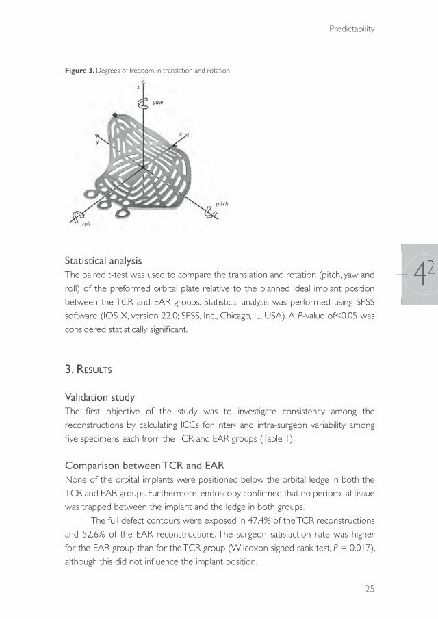
Predictability
125
42
Figure 3. Degrees of freedom in translation and rotation
Statistical analysisThe paired t-test was used to compare the translation and rotation (pitch, yaw and roll) of the preformed orbital plate relative to the planned ideal implant position between the TCR and EAR groups. Statistical analysis was performed using SPSS software (IOS X, version 22.0; SPSS, Inc., Chicago, IL, USA). A P-value of<0.05 was considered statistically significant.
3. results
Validation studyThe first objective of the study was to investigate consistency among the reconstructions by calculating ICCs for inter- and intra-surgeon variability among five specimens each from the TCR and EAR groups (Table 1).
Comparison between TCR and EARNone of the orbital implants were positioned below the orbital ledge in both the TCR and EAR groups. Furthermore, endoscopy confirmed that no periorbital tissue was trapped between the implant and the ledge in both groups.
The full defect contours were exposed in 47.4% of the TCR reconstructions and 52.6% of the EAR reconstructions. The surgeon satisfaction rate was higher for the EAR group than for the TCR group (Wilcoxon signed rank test, P = 0.017), although this did not influence the implant position.
39372 Dubois, Leander.indd 125 04-03-16 10:19

Chapter 42
126
There was no statistically significant difference (P> 0.05) in the degree of implant dislocation (translation, pitch, yaw and roll) between the TCR and EAR groups (Tables 2). Plots of the implant positions and most frequent translations and rotations are shown in Figures 4,5. Table 1. Inter-class correlation coefficients (ICC) for inter- and intra-surgeon variability
Conventional Endoscopeintra inter intra inter
translation .69195%Ci[.106-.921]
.32295%Ci [-.348-.774]
.68495%Ci[-.093-.919]
.46695%Ci[-.189-.843]
pitch .25495%Ci[-.451-763]
.06795%Ci[-.557-.643]
.75895%Ci[-.243-940]
.47395%Ci[-.181-.837]
yaw .53395%Ci[-.150-.871]
.38595%Ci[-.283-.801]
.64795%Ci[-.026-908]
.30595%Ci[-.364-766]
roll .74295%Ci[.208-.935]
.59995%Ci[-.005-.883]
.10595%Ci[-.564-.691]
.08995%Ci[-.542-.656]
Table 2. Implant positions with conventional transconjunctival reconstruction and endoscopic-assisted reconstruction
Conventional Endoscope Paired t-test
Mean SD Mean SD t= df p=
(LD)translation 4.98mm 2.19mm 4.18mm 2.06mm 1.36 18 0.19
pitch -1.29° 3.05° -0.25° 3.65° -1.22 18 0.24yaw 17.81° 10.91° 14.53° 11.88° 1.55 18 0.14roll -9.81° 9.09° -7.12° 5.65° -1.36 18 0.19
(PG)translation 4.90mm 1.35mm 5.54 mm 1.58mm 1.36 9 0.14
pitch -0.43° 6.26° -1.81° 2.76° 1.14 9 0.28yaw 21.99° 13.17° 19.06° 7.73° 1.19 9 0.27roll -11.91° 6.13° -12.73° 7.52° 0.36 9 0.73
39372 Dubois, Leander.indd 126 04-03-16 10:19
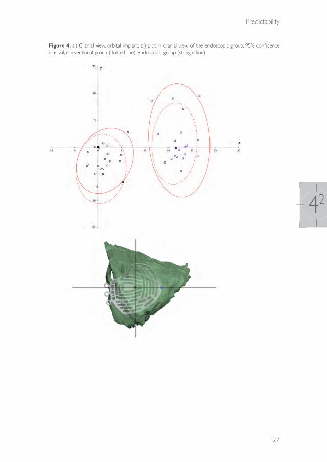
Predictability
127
42
Figure 4. a.) Cranial view, orbital implant; b.) plot in cranial view of the endoscopic group; 95% confidence interval, conventional group (dotted line), endoscopic group (straight line)
39372 Dubois, Leander.indd 127 04-03-16 10:19
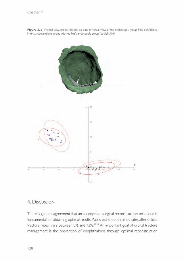
Chapter 42
128
Figure 5. a.) Frontal view, orbital implant; b.) plot in frontal view of the endoscopic group; 95% confidence interval, conventional group (dotted line), endoscopic group (straight line)
4. discussiOn
There is general agreement that an appropriate surgical reconstruction technique is fundamental for obtaining optimal results. Published enophthalmos rates after orbital fracture repair vary between 8% and 72%.27,28 An important goal of orbital fracture management is the prevention of enophthalmos through optimal reconstruction
39372 Dubois, Leander.indd 128 04-03-16 10:19

Predictability
129
42
of the lost anatomical boundaries. Evaluation of changes in orbital volume and periorbital contents during surgery is difficult. In addition to traumatic discontinuity of the bony orbit, the loss of orbital soft tissue is also a possibility and is hard to quantify clinically. Moreover, validation of the orbital volume is unpredictable because of impaired visualization, which may produce sequellae such as cicatricial or volume-related atrophy. Even correct implant placement may not always lead to optimal clinical outcomes.29
In our opinion, a cadaveric study model has distinct advantages in terms of verifying the quality of treatment. Treating the same fracture twice under comparable circumstances facilitates the comparison of both methods in the same specimen and allows the evaluation of intra- and inter-surgeon variability. Tissue consistency differs among cadaveric and in vivo studies, and major clinical parameters, such as enopthalmos and diplopia, cannot be assessed in cadaveric studies. Because this study focused on the loss of anatomical boundaries and optimal reconstruction, textural differences between the cadaveric setting and the actual clinical setting were considered acceptable. The periorbital tissue component is difficult to assess in cadavers because of increased consistency of the orbital fat; however, bony reconstruction, which is of fundamental importance, was the prime focus of this study.
ICCs were determined to calculate inter- and intra-surgeon variability as an assessment tool for consistency in the quantitative measurements (translation and rotation). Although the consistency was low, the TCR and EAR groups showed similar results, suggesting that additional visualization does not increase the reproducibility of implant placement. Comparable in vivo data are difficult to obtain because it is uncommon to reconstruct an orbit more than once.
EndoscopeEndoscopic surgery gained popularity in the early 1980s and has become synonymous with minimally invasive treatment in many regions of the body.30 It is well integrated in most surgical fields, resulting in a wide availability of proper endoscopes in most operation theatres. The maxillary sinus is a large cavity and can be used for visualization and instrumentation. However, studies have shown that the indications for endoscopic orbital surgery are limited. To date, most blow-out fractures are probably best treated through an open approach.22
39372 Dubois, Leander.indd 129 04-03-16 10:19
Chapter 42
130
The transorbital endoscopic-assisted approach has been suggested as a good alternative for the assessment and reconstruction of large complex orbital wall fractures with involvement of both the medial wall and floor regions.11,21 The endoscope helps the clinician to verify the position of the implant on the apical ledge. Polligkeit et al.16 suggested that ECR provides good visualization of the orbital floor, with technically easy implant placement. However, implant positioning on the orbital ledge is not the only condition for optimal implant placement. A misplaced orbital implant can result from translation or rotation in the orbital cavity while it rests on the orbital ledge. This may increase the orbital volume and lead to enophthalmos.
Although Hundepool et al.14 showed a better clinical outcome for EAR than for TCR, they did not investigate volumetric changes and implant position. The present study showed similar results for orbital implant positions between the TCR and EAR groups. The prime focus of this study was ideal implant positioning, and the results demonstrated that additional endoscopic visualization with the transantral approach does not significantly increase the accuracy of implant placement.
The drawbacks of the endoscopic approach include the requirement of an additional intra-oral incision and a surgical duration that is prolonged by an average of 15 min compared with the conventional procedure.14 Possible minor complications of antrostomy include numbness of the skin and mucosa innervated by the infraorbital nerve and mucosal defects caused by removal of the sinus mucosa to enable visualization. Theoretically, a combined endoscopic and transconjunctival approach enables better visualization of the bony defect along the orbital floor, as suggested in previous studies,14,21,31,32 and better control during implant positioning on the posterior bony ledge. However, the present study does not show the latter advantage. An important advantage of the endoscope, which is unrelated to the outcome, is that it allows for the demonstration of the surgery to students and trainees on a screen.
Additional evidence detailing the advantages of endoscopic-assisted reconstruction is limited. Most clinical studies are hampered by small patient samples, the lack of control groups and randomization and poor description of the fracture complexity. In clinical studies where fully endoscopic orbital reconstructions are compared with transorbital reconstructions, bias is introduced by the inclusion of smaller fractures, which are typically treated by endoscopic reconstruction.33,34 Comparison of the clinical outcomes of treatments for different types of orbital fractures is difficult. Larger fractures are prone to suboptimal volume correction, which may cause enophthalmos.
39372 Dubois, Leander.indd 130 04-03-16 10:19
Predictability
131
42
Orbital implant positionIn this study, the Orbital Implant Dislocation Frame (OIDF) was used to assess implant position and compare the surgical results. Various methods for the evaluation of implant position after orbital reconstruction have been described,6,7,35-39 but distance measurements are the most frequently described. The goal of this study was to assess the influence of endoscopic assistance on the predictability of implant positioning accuracy during orbital reconstruction. Therefore, individual quantification of all displacement parameters and assessment of potential improvement in each dislocation parameter are critical. The OIDF method facilitates both these steps. An additional advantage is that comparisons among methods, surgeons and specimens are feasible; differences in orbital shape among specimens do not influence the quantification of orbital implant position.7
In our study, none of the implants were positioned below the orbital ledge, and only one reconstruction was associated with the protrusion of orbital fat below the implant. Although cadaver stiffness probably limits the occurrence of fat prolapse, the visibility is comparable to that observed in vivo. Accordingly, the main concern is adequate positioning of the implant and prevention of its rotation. Although the yaw decreased for 3.28°, the changes were not significant (P = 0.14).
5. cOnclusiOn
The use of the endoscope overestimates the surgeon’s ability to place implants accurately. The results of this study suggest that endoscopic-assisted orbital reconstruction is helpful for the visualization of orbital defects and is useful for training; however, it offers no additional benefits in terms of accurate implant positioning during the anatomical reconstruction of complex orbital defects
AcknowledgementsWe thank Nick H.J. Lobé, a radiological technician, and Eric J. Lichtenberg and Petra E.M.H. Habets from the Department of Anatomy, Embryology and Physiologyfor their assistance in logistics and cadaveric scanning. We also thank Irene H. A. Aartman for her advice on statistical analysis.
All orbital implants for this study were donated, and their stereolithographic files were provided by KLS Martin.
39372 Dubois, Leander.indd 131 04-03-16 10:19
Chapter 42
132
references
1. Hammer B. In: Orbital fractures: diagnosis, operative treatment, secondary corrections. Hogrefe & Huber Publishers, 1995.
2. Burnstine MA. Clinical recommendations for repair of isolated orbital floor fractures: an evidence-based analysis. Ophthalmology. 2002: 109: 1207-13.
3. Dubois L, Steenen SA, Gooris PJJ, Mourits MP, Becking AG. Controversies in orbital reconstruction-I. Defect-driven orbital reconstruction: a systematic review. Int J Oral Maxillofac Surg. 2015: 44: 308-15.
4. Bell RB, Markiewicz MR. Computer-assisted planning, stereolithographic modeling, and intraoperative navigation for complex orbital reconstruction: a descriptive study in a preliminary cohort. J Oral Maxillofac Surg. 2009: 67: 2559-70.
5. Markiewicz MR, Dierks EJ, Bell RB. Does intraoperative navigation restore orbital dimensions in traumatic and post-ablative defects? J Craniomaxillofac Surg. 2012: 40: 142-8.
6. Essig H, Dressel L, Rana M, Rana M, Kokemueller H, Ruecker M, Gellrich NC. Precision of posttraumatic primary orbital reconstruction using individually bent titanium mesh with and without navigation: a retrospective study. Head Face Med. 2013: 9:18.
7. Schreurs R, Dubois L, Becking AG, Maal TJJ: Measuring predictability in orbital reconstruction: quantitative assessment of orbital implant position. PLOS ONE (unpublished results)
8. Dubois L, Steenen SA, Gooris PJJ, Mourits MP, Becking AG. Controversies in orbital reconstruction. II. Timing of post-traumatic orbital reconstruction: a systematic review. Int J Oral Maxillofac Surg. 2015: 44: 433-40.
9. Manson PN, Grivas A, Rosenbaum A, Vannier M, Zinreich J, Iliff N. Studies on enophthalmos: II. The measurement of orbital injuries and their treatment by quantitative computed tomography. Plast Reconstr Surg. 1986: 77: 203.
10. Rana M, Essig H, Rücker M, Ruecker M, Gellrich NC. Development and demonstration of a novel computer planning solution for predefined correction of enophthalmos in anophthalmic patients using prebended 3D titanium-meshes – a technical note. J Oral Maxillofac Surg. 2012: 70: 631-8
11. Kakibuchi M, Fukazawa K, Fukuda K, Yamada N, Matsuda K, Kawai K, Tomofuji S, Sakagami M. Combination of transconjunctival and endonasal-transantral approach in the repair of blowout fractures involving the orbital floor. Br J Plast Surg. 2004: 57: 37-44.
12. Jin H-R, Yeon J-Y, Shin S-O, Choi Y-S, Lee D-W. Endoscopic versus external repair of orbital blowout fractures. Otolaryngol Head Neck Surg. 2007: 136: 38-44.
13. Ducic Y. Endoscopic transantral repair of orbital floor fractures. Otolaryngol Head Neck Surg. 2009: 140: 849-54.
14. Hundepool AC, Willemsen MAP, Koudstaal MJ, van der Wal KGH. Open reduction versus endoscopically controlled reconstruction of orbital floor fractures: a retrospective analysis. Int J Oral Maxillofac Surg. 2012: 41: 489-93.
15. Balakrishnan K, Moe KS. Applications and outcomes of orbital and transorbital endoscopic surgery. Otolaryngol Head Neck Surg. 2011: 144: 815-20.
16. Polligkeit J, Grimm M, Peters JP, Cetindis M, Krimmel M, Reinert S. Assessment of indications and clinical outcome for the endoscopy-assisted combined subciliary/transantral approach in treatment of complex orbital floor fractures. J Craniomaxillofac Surg. 2013: 41: 797-802.
17. Farwell DG, Sires BS, Kriet JD, Stanley RB. Endoscopic repair of orbital blowout fractures: use or misuse of a new approach? Arch Facial Plast Surg. 2014: 9: 427-33.
18. Converse JM, Smith B. Reconstruction of the floor of the orbit by bone grafts. Arch Ophthalmol. 1950: 44: 1-21.
19. Walter WL. Early surgical repair of blowout fracture of the orbital floor by using the transantral approach. South Med J. 1972: 65: 1229-43.
20. Strong EB. Endoscopic repair of orbital blow-out fractures. Facial Plast Surg. 2004: 20: 223-30.
21. Shi W, Jia R, Li Z, He D, Fan X. Combination of transorbital and endoscopic transnasal approaches to repair orbital medial wall and floor fractures. J Craniofac Surg. 2012: 23: 71-4.
39372 Dubois, Leander.indd 132 04-03-16 10:19

Predictability
133
42
22. Farwell DG, Strong EB. Endoscopic repair of orbital floor fractures. Facial Plast Surg Clin North Am. 2006: 14: 11-6.
23. Kwon JH, Kim JG, Moon JH, Cho JH. Clinical analysis of surgical approaches for orbital floor fractures. Arch Facial Plast Surg. 2008: 10: 21-4.
24. Chen CT, Chen YR. Broad application of the endoscope for orbital floor reconstruction: long-term follow-up results. Plastic Reconstr Surg. 2010: 125: 969-78.
25. Jaquiéry C. Reconstruction of orbital wall defects: critical review of 72 patients. Int J Oral Maxillofac Surg. 2007: 36: 193-199.
26. Kunz C, Sigron GR, Jaquiéry C. Functional outcome after non-surgical management of orbital fractures – the bias of decision-making according to size of defect: critical review of 48 patients. Br J Oral Maxillofac Surg. 2013: 51: 486-92.
27. Converse JM, Smith B, Obear MF, Wood-Smith D. Orbital blowout fractures: a ten-year survey. Plast Reconstr Surg. 1967: 39: 20-36.
28. Cole P, Boyd V, Banerji S, Hollier Jr LH. Comprehensive management of orbital fractures. Plast Reconstr Surg. 2007: 120: S57-63.
29. Andrades P, Hernandez D, Falguera MI, Millan JM, Heredero S, Gutierrez R, Sánchez-Aniceto G. Degrees of tolerance in post-traumatic orbital volume correction: the role of prefabricated mesh. J Oral Maxillofac Surg. 2009: 67: 2404-11.
30. Ye L, Liu J, Tang Y, et al. Endoscopic minimal invasive cholecystolithotomy vs laparoscopic cholecystectomy in treatment of cholecystolithiasis in China: a meta-analysis. Int J Surg. 2015: 13: 227-38.
31. Strong EB. Endoscopic repair of orbital blow-out fractures. Oper Tech Otolaryngol Neck Surg. 2006: 17: 201-9.
32. Kakibuchi M, Fukazawa K, Fukuda K, Yamada N, Matsuda K, Kawai K, Tomofuji S, Sakagami M. Combination of transconjunctival and endonasal-transantral approach in the repair of blowout fractures involving the orbital floor. Br J Plast Surg. 2014: 57: 37-44.
33. Chen CT, Chen YR. Endoscopically assisted repair of orbital floor fractures. Plast Reconstr Surg. 2001: 108: 2011-18; discussion 2019.
34. Ducic Y. Endoscopically assisted diagnosis and treatment of maxillofacial fractures. J Otolaryngol. 2001: 30: 149-53.
35. Cai EZ, Koh YP, Hing ECH, Low JR, Shen JY, Wong HC, Gangadhara S, Lim TC. Computer-assisted navigational surgery improves outcomes in orbital reconstructive surgery. J Craniofac Surg; 2012: 23: 1567-73.
36. Strong EB, Fuller SC, Wiley DF, Zumbansen J, Wilson MD, Metzger MC. Preformed vs intraoperative bending of titanium mesh for orbital reconstruction. Otolaryngol Head Neck Surg. 2013: 149: 660-6.
37. Novelli G, Tonellini G, Mazzoleni F, Bozzetti A, Sozzi D. Virtual surgery simulation in orbital wall reconstruction: integration of surgical navigation and stereolithographic models. J Craniomaxillofac Surg. 2014: 42:2025-34.
38. Metzger MC, Hohlweg-Majert B, Schon R,Teschner M, Gellrich NC, Schmelzeisen R, Gutwald R. Verification of clinical precision after computer-aided reconstruction in craniomaxillofacial surgery. Oral Surg Oral Med Oral Pathol Oral Radiol Endod. 2007: 104: 1-10.
39. Gander T, Essig H, Metzler P,Lindhorst D, Dubois L, Rücker M, Schumann P. Patient specific implants (PSI) in reconstruction of orbital floor and wall fractures. J Craniomaxillofac Surg. 2015: 43: 126-30.
39372 Dubois, Leander.indd 133 04-03-16 10:19

39372 Dubois, Leander.indd 134 04-03-16 10:19
CHAPTER 43
Navigation assisted orbital reconstruction
This chapter is an edited version of the manuscript: Dubois L , Schreurs R, Jansen J, Essig H, Gooris PJJ, Maal TJJ, Becking AG:
Predictability in orbital reconstruction: A human cadaver study, part II: Navigation-assisted orbital reconstruction. J Craniomaxillofac Surg. 2015: 43: 2042-9.
39372 Dubois, Leander.indd 135 04-03-16 10:19
Chapter 43
136
1. intrOductiOn
The orbit is often affected by traumatic injuries, which can result in esthetic deficits and functional ocular impairment, especially when the reconstruction is suboptimal.1 Precise reconstruction of the orbit is the primary step in restoring normal function and esthetics of the orbit; however, it is difficult to accomplish.2 The complexity of orbital reconstruction in post-traumatic and post-ablative defects is well described in the published literature.2-11
Reconstruction outcome is unpredictable because of the difficulty of optimally reconstructing the complex orbital contour.11-13 Anatomical orbital landmarks function as important surgical guides and may be helpful during reconstruction of the orbit. However, it may be difficult to locate the posterior ledge, which is the most important dorsal anatomical landmark and provides essential support for reconstruction material.3,14,15 This is especially the case in a traumatized orbit with the combination of a comminuted fracture of the thin orbital floor and disrupted orbital soft tissue.
Limited surgical exposure hinders the view of the orbital defect and the verification of implant position during surgery,13 which may be an important reason for suboptimal placement of the implant and for unsatisfactory outcomes such as enophthalmos and/or diplopia. Manson et al.14 were the first to associate improper implant positioning with inadequate restoration of orbital volume, resulting in enophthalmos.
Recently, preoperative computer-assisted planning with virtual implant placement has been combined with intraoperative navigation in an attempt to reconstruct the bony orbit more accurately and optimize treatment outcome. The first step in computer-assisted surgery for orbital reconstruction is segmenting the orbital walls and orbital volume. By using a mirroring technique,9,16 the unaffected side can be copied to the deformed side, creating a template for a custom-made ideal orbit. The outcome of the surgical correction depends on the shape and positioning of the orbital implants.8,9,17 One advantage of using a preformed implant is that a stereolithographic (STL) software file of the implant can be used preoperatively to find the optimal fit and position in a digital environment (Figure 1). However, an optimally formed implant does not automatically result in optimal implant placement (Figure 2).
39372 Dubois, Leander.indd 136 04-03-16 10:19
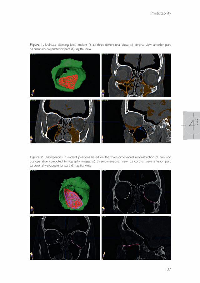
Predictability
137
43
Figure 1. BrainLab planning: ideal implant fit a.) three-dimensional view; b.) coronal view, anterior part; c.) coronal view, posterior part; d.) sagittal view
Figure 2. Discrepancies in implant positions based on the three-dimensional reconstruction of pre- and postoperative computed tomography images. a.) three-dimensional view; b.) coronal view, anterior part; c.) coronal view, posterior part; d.) sagittal view
39372 Dubois, Leander.indd 137 04-03-16 10:19
Chapter 43
138
A computer model can be used intraoperatively as a virtual template to navigate the preplanned bony contours and assess implant fit. Intraoperative navigation assists the surgeon in optimal reconstruction.5,18-22 Wilde and Schramm1 suggested that computer-assisted surgery helps achieve predictable outcomes in reconstruction. In the largest clinical cohort study (n =104) published to date, Yu et al.22 demonstrated that navigation-assisted surgery (NAS) provided promising and accurate results for the treatment of midfacial deformities. As described by Zhang et al.,23 NAS probably increases predictability and could become an essential part of the workflow for complex orbital reconstructions. Markewietz et al.13 concurred with the authors of previous reports and concluded that future studies should explore whether NAS is preferable to conventional techniques for true-to-origin orbital reconstruction.
The aim of this study was to assess the predictability of navigation-assisted orbital reconstruction for implant positioning in complex defects in a human cadaver model (Class III-IV).11
2. Materials and MethOds
MaterialsThe human specimens used for this study had been previously used for a study of endoscopic-assisted orbital reconstruction.24 Ten human cadaver heads were obtained from the Department of Anatomy of the Academic Medical Centre of the University of Amsterdam. One orbit was excluded because of sinus pathology (osteoma), resulting in a total of 19 orbits eligible for this study.
The orbital floor and medial wall were fully exposed through a standard transconjunctival incision and retroseptal preparation. Following the Jaquiéry classification,25,26 complex orbital defects (Class III-IV) were created with piezoelectric surgery (Mectron, Carasco, Italy) Computed tomographic scans of the cadaver heads were performed at baseline (with intact orbits, T0), after creation of the orbital defects (T1), and postoperatively after implant placement (T2) (Sensation 64, Siemens Medical Solutions, Forchheim, Germany). Scan parameters included collimation of 20 × 0.6 mm, 120 kV, 350 mAs, pitch 0.85, FOV 30 cm, matrix 512 × 512, reconstruction slice thickness of 0.75 mm with overlapping increments of 0.4 mm, bone kernel H70s, and bone window W1600 L400.
39372 Dubois, Leander.indd 138 04-03-16 10:19
Predictability
139
43
Validation studyThe poor consistency of traditional orbital reconstruction, as has been described in an endoscope study,24 is shown in Table 1. A validation study was performed to investigate the consistency of navigation-assisted orbital reconstruction. Two oral and maxillofacial surgeons (LD and PS), experienced in the field of orbital reconstruction, performed 10 orbital reconstructions on the cadaver heads using preformed orbital titanium mesh plates (KLS Martin, Tuttlingen, Germany) and a navigation-assisted workflow (Curve, BrainLAB AG, Feldkirchen, Germany).
MethodsIn the first surgical session, all 19 orbits were reconstructed with a transconjunctival approach (traditional group) by both surgeons (LD, PG). In a second session, the orbits were reconstructed with a transconjunctival approach combined with navigation by the same surgeon. The implant was placed in the correct position according to the navigation outcomes. The implants were fixed with one bone screw. The drill holes were covered and camouflaged between the two sessions by filling with DuraLay (Reliance Dental Mfg. Co., Worth, Illinois, USA). For the consistency of measurement, one surgeon (LD) performed the reconstructions twice for both groups. After each reconstruction, the surgeon filled out a questionnaire regarding the perceived predictability and quality of reconstruction. These methods were similar to those used by the same research group in a previous study on endoscopic-assisted orbital reconstruction.24
Contour analysisThe quality of the reconstruction was evaluated using iPlan software (version 3.05, BrainLAB AG, Feldkirchen, Germany). The optimal implant position was determined by information from the T0 and T1 scans with two surgeons (LD, PG) in agreement. In both the traditional and navigation groups, the postoperative (T2) scan was superpositioned on the T0 scan with the Image Fusion modality, available in the iPlan software. A threshold segmentation with a threshold of≥1200 Hounsfield units was performed to segment the resulting implant in the T2 scan. The osteosynthesis screw and excess bony tissue were removed from the segmentation result because these structures were not present in the STL model of the planned implant. The three proximal osteosynthesis rings were excluded because their position could have been altered during the surgery by bending. An STL model of the planned implant and the segmentation of the resulting implant were exported from the iPlan software. The
39372 Dubois, Leander.indd 139 04-03-16 10:19
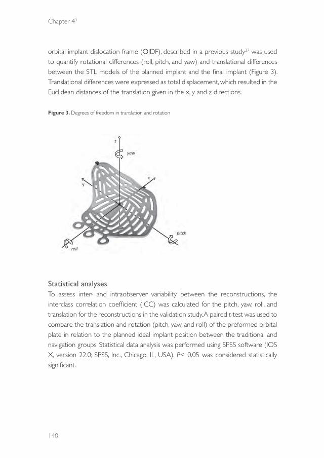
Chapter 43
140
orbital implant dislocation frame (OIDF), described in a previous study27 was used to quantify rotational differences (roll, pitch, and yaw) and translational differences between the STL models of the planned implant and the final implant (Figure 3). Translational differences were expressed as total displacement, which resulted in the Euclidean distances of the translation given in the x, y and z directions.
Figure 3. Degrees of freedom in translation and rotation
Statistical analysesTo assess inter- and intraobserver variability between the reconstructions, the interclass correlation coefficient (ICC) was calculated for the pitch, yaw, roll, and translation for the reconstructions in the validation study. A paired t-test was used to compare the translation and rotation (pitch, yaw, and roll) of the preformed orbital plate in relation to the planned ideal implant position between the traditional and navigation groups. Statistical data analysis was performed using SPSS software (IOS X, version 22.0; SPSS, Inc., Chicago, IL, USA). P< 0.05 was considered statistically significant.
39372 Dubois, Leander.indd 140 04-03-16 10:19

Predictability
141
43
3. results
Validation studyThe consistency of the orbital implant position in terms of translation (ICC 0.76, 95% confidence interval [CI] 0.25–0.94) and rotation (pitch: ICC 0.78, 95% CI 0.30–0.95; yaw: ICC 0.87, 95% CI 0.53–0.97; roll: ICC 0.51, 95% CI 0.18–0.86) was high in the navigation group. The consistency in orbital reconstruction was lower in the traditional group than in the navigation group (Table 1).
Table 1. Interclass correlation coefficient (ICC)
Conventional Navigation
intra inter intra inter
translation .69195%Ci[.106-.921]
.32295%Ci [-.348-.774]
.76095%Ci[.246-.940]]
.66595%Ci[.314-.856]
pitch .25495%Ci[-.451-763]
.06795%Ci[-.557-.643]
.78395%Ci[.300-.947]
.67595%Ci[.330-.861]
yaw .53395%Ci[-.150-.871]
.38595%Ci[-.283-.801]
.87195%Ci[.533-.969]
.30195%Ci[-.165-.657]
roll .74295%Ci[.208-.935]
.59995%Ci[-.005-.883]
.51295%Ci[-.177-864)
.28395%Ci[-.184-.646]
Comparison of traditional and navigation groupsOn the CT images, none of the orbital implants were positioned below the ledge in the traditional or navigation groups.
Full-defect contours were exposed in 47.4% of the reconstructions in the traditional group. However, defect boundaries were visualised by navigation in 100% of the reconstructions in the navigation group. The surgeons’ satisfaction rate was lower in the traditional group than in the navigation group (Wilcoxon signed rank test,P<0.001), which was in accordance with the actual postoperative results.
The difference between the two groups in implant position (translation, yaw, and roll) was statistically significant, with the navigation group showing more favourable results (paired t-test, P< 0.05; Table 2).
39372 Dubois, Leander.indd 141 04-03-16 10:19

Chapter 43
142
Table 2. Implant position in conventional transconjunctival reconstruction vs navigation-assisted reconstruction; * = significant
Conventional Navigation Paired t-testMean SD Mean SD t= df p=
(LD)
translation 4.98mm 2.19mm 3.29mm 1.64mm 3.60 18 0.002*
pitch -1.29° 3.05° -1.13° 2.15° -0.30 18 0.77yaw 17.81° 10.91° 8.82° 8.05° 4.51 18 <0.001*roll -9.81° 9.09° -2.3° 4.79° -3.81 18 0.001*(PG)translation 4.90mm 1.35mm 4.15 mm 1.35mm 2.27 9 0.05*
pitch 0.43° 6.26° -2.10° 3.46° 1.58 9 0.15yaw 21.99° 13.17° 7.94° 10.5° 2.28 9 0.05*roll -11.91° 6.13° -9.60° 5.13° -1.56 9 0.15
Even in cases of navigation-assisted orbital reconstruction, medial wall involvement resulted in significantly higher yaw than reconstructions in orbits with intact medial walls (independent sample t-test, P=0.008). However, medial wall involvement was not associated with significant differences in translation, pitch, or roll (Table 3). More complex defects (Class III vs. IV) were not associated with a higher degree of implant dislocation (independent sample t-test, P>0.05; Table 4).
Table 3. Effect of medial wall involvement on planned vs. realized orbital implant position by using the orbital implant dislocation frame (navigation group); * = significant
no medial wall# medial wall #Mean SD Mean SD p
translation 3.24 1.86 3.32 1.51 0.91
Pitch -0.57 2.60 -1.63 1.63 0.30Yaw 3.97 6.40 13.19 6.95 0.008*Roll -4.12 5.37 -.68 3.75 0.17
Table 4. Effect of complexity of the defect on planned vs. realized orbital implant position by using the orbital implant dislocation frame (navigation group); * = significant
Class 3 Class 4Mean SD Mean SD p
translation 3.15 1.69 3.47 1.64 0.68
Pitch -1.54 2.12 -0.57 2.2 0.35Yaw 10.71 5.81 6.25 10.24 0.24Roll -2.06 5.22 -2.65 4.45 0.80
39372 Dubois, Leander.indd 142 04-03-16 10:19

Predictability
143
43
Plots of the implant positions and the most frequent translations and rotations are shown in Figures 4 and 5. The 95% confidence interval has been marked for both groups.
Figure 4. a.) Cranial view, orbital implant; b.) plot in cranial view of the navigation group; 95% confidence interval, conventional group (dotted line), navigation group (straight line)
39372 Dubois, Leander.indd 143 04-03-16 10:19
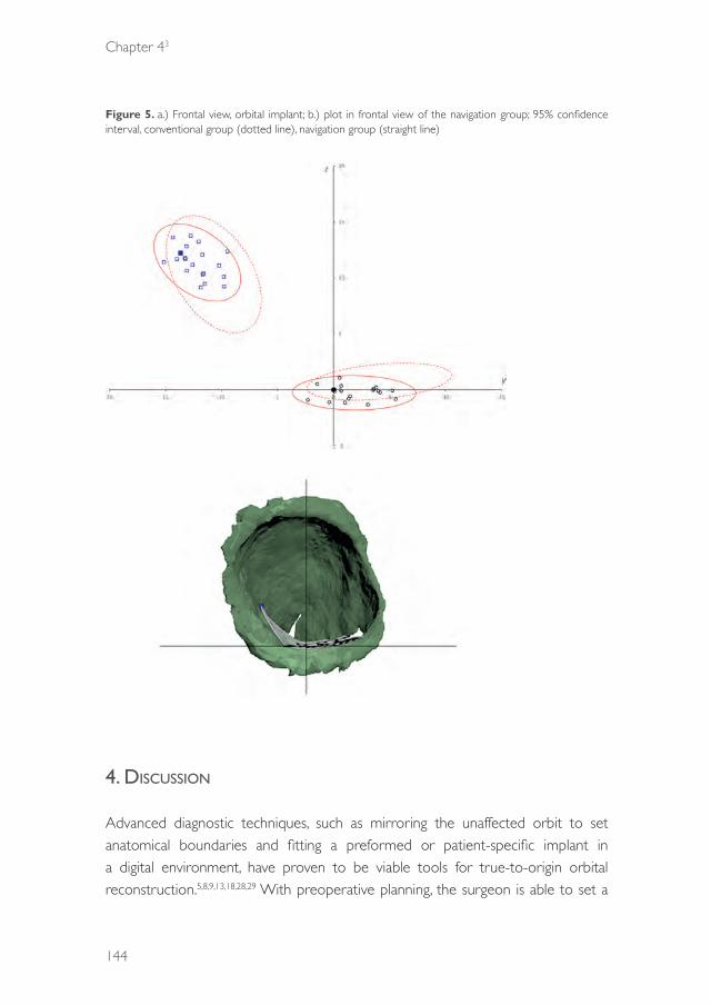
Chapter 43
144
Figure 5. a.) Frontal view, orbital implant; b.) plot in frontal view of the navigation group; 95% confidence interval, conventional group (dotted line), navigation group (straight line)
4. discussiOn
Advanced diagnostic techniques, such as mirroring the unaffected orbit to set anatomical boundaries and fitting a preformed or patient-specific implant in a digital environment, have proven to be viable tools for true-to-origin orbital reconstruction.5,8,9,13,18,28,29 With preoperative planning, the surgeon is able to set a
39372 Dubois, Leander.indd 144 04-03-16 10:19
Predictability
145
43
clear target for ideal implant position. However, the relationship between the final position and the planned position must be verified intraoperatively. NAS provides the surgeon with an intraoperative tool for orientation and comparison of the actual implant location with the target location, presumably preventing improper implant placement.
Several reports have described the use of intraoperative navigation for orbital reconstruction of post-traumatic defects.5,8,18,19,20,22,23,30 Some of these studies showed that navigation-assisted orbital reconstruction is effective in restoring orbital volume and globe dimensions in complex defects.5,8,13,23,28 However, none of these studies compared the effects of orbital reconstruction with and without the use of intraoperative navigation. The proposed study is the first study directly comparing the effect of navigation on orbital reconstructive surgery within the same specimen.
This study clearly indicates that NAS is a reliable tool that enables significantly better and more consistent orbital implant placement. It may also reduce the risk of improper placement for experienced orbital surgeons who have no experience with navigation (PG). A common cause of inaccurate implant placement is the inability to define the posterior orbital ledge.14,15 In our study, none of the implants were positioned below the ledge, even in the traditional group. This study demonstrates that when navigation is not used, suboptimal implant placements by experienced surgeons are most frequently caused by translation in the x-axis, in combination with yaw (Figures 4, 5). NAS significantly reduces these translation and rotation errors. Perfect placement was defined as the difference between the planned position and acquired position within a calibration error of 1-2 mm,17,23,31 which corresponds to a deviation of less than 1 mm per axis and a yaw of less than 8 degrees. Although navigation enables significantly better placement than other techniques while retaining a similar level of precision,9,13,28,29 it is still not perfect. More predictable true-to-origin reconstructions may be possible with further development of the technology. Given the current dissimilarities, our group promotes intraoperative imaging as an additional tool to check the orbital implant position.
Although NAS can be used for all orbital reconstructions, previous studies have suggested that it is primarily beneficial for complex defects.5,9,13 Complex defects include those with medial wall involvement, loss of the transition zone, or orbital defects extending to the posterior third of the orbital floor. Through the combination
39372 Dubois, Leander.indd 145 04-03-16 10:19

Chapter 43
146
of medial and inferior-posterior orbital fat bulging, it may often be difficult to place the implant in the optimal position. In this study, NAS significantly reduced improper implant placements in these complex defects, as compared to conventional implant placement performed without the aid of image-guided navigation.
This study was performed with cadavers to directly compare the quality of orbital reconstruction with and without intraoperative navigation. In our opinion, a cadaver study has many advantages for verifying the quality of treatment options. Treating the same fracture twice under comparable circumstances makes it possible to compare both methods on the same cadaver and to evaluate intra- and intersurgeon variability.24 The laboratory setting is also free of the stress and distraction of a clinical situation, where time constraints, psychological stress, and fatigue may come into play. However, cadaver tissues are of a different consistency than those of living patients, and a cadaver model lacks important clinical problems such as enophthalmos and diplopia. Because this study focused on lost anatomical boundaries and optimal reconstruction, the texture of the human cadaver specimen was acceptable. Peri-orbital tissues are difficult to assess in cadavers because of the increased fibrosity of the orbital fat, but the main focus of this study was reconstruction of the bones, which is of fundamental importance.
Most studies use orbital volume and reduction of volume as tools to describe the effect of the reconstruction.13,28,32-34 As described by Strong et al.,35 orbital volume is an important predictor of enophthalmos. However, critically assessing the actual implant position is also an important factor. As shown by Schreurs et al.,27 even a malpositioned orbital implant can lead to a significant reduction of orbital volume and a good clinical outcome, although it is not the desired result (Figure 6).
By using the OIDF, the actual result can be instantly compared to the desired result, and the differences between planned and actual results may be quantified for all rotational and translational parameters.27 In NAS, an important surgical goal is created in the preoperative planning phase; NAS is regarded as target surgery. The additional value of navigation assistance in orbital reconstructive surgery can therefore be quantified only if the surgical outcome is compared to the surgical target. Comparing the location of the final implant with that of the planned implant makes it possible to compare accuracy and predictability between traditional and navigationreconstructions.27 In our study, additional analysis with the OIDF enabled
39372 Dubois, Leander.indd 146 04-03-16 10:19
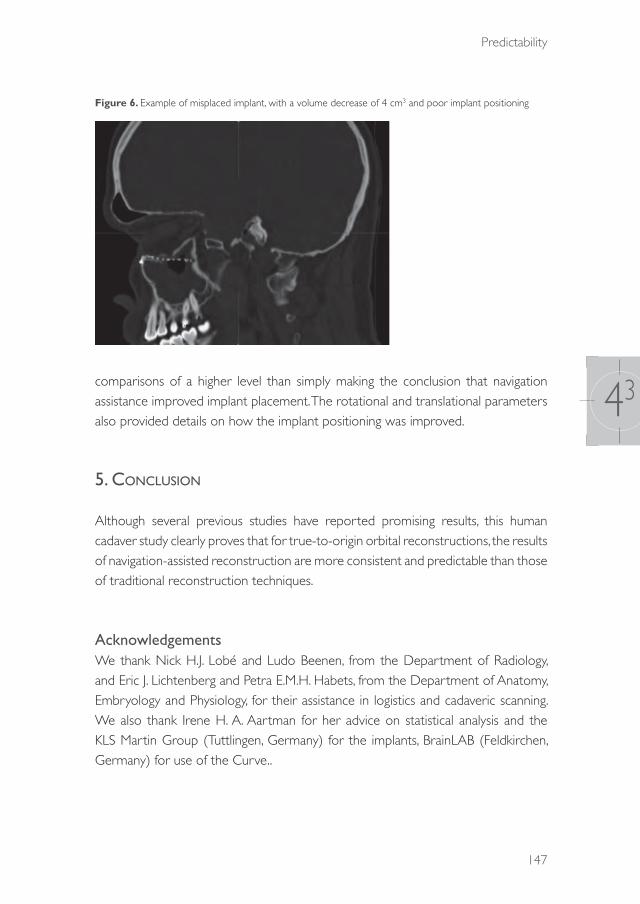
Predictability
147
43
Figure 6. Example of misplaced implant, with a volume decrease of 4 cm3 and poor implant positioning
comparisons of a higher level than simply making the conclusion that navigation assistance improved implant placement. The rotational and translational parameters also provided details on how the implant positioning was improved.
5. cOnclusiOn
Although several previous studies have reported promising results, this human cadaver study clearly proves that for true-to-origin orbital reconstructions, the results of navigation-assisted reconstruction are more consistent and predictable than those of traditional reconstruction techniques.
AcknowledgementsWe thank Nick H.J. Lobé and Ludo Beenen, from the Department of Radiology, and Eric J. Lichtenberg and Petra E.M.H. Habets, from the Department of Anatomy, Embryology and Physiology, for their assistance in logistics and cadaveric scanning. We also thank Irene H. A. Aartman for her advice on statistical analysis and the KLS Martin Group (Tuttlingen, Germany) for the implants, BrainLAB (Feldkirchen, Germany) for use of the Curve..
39372 Dubois, Leander.indd 147 04-03-16 10:19
Chapter 43
148
references
1. Wilde F, Schramm A. Intraoperative imaging in orbital and midface reconstruction. Facial Plast Surg. 2014;30(5):545-53. doi:10.1055/s-0034-1393700.
2. Dubois L, Steenen SA, Gooris PJJ, Mourits MP, Becking AG. Controversies in orbital reconstruction. I. Defect-driven orbital reconstruction: a systematic review. Int J Oral Maxillofac Surg. 2015: 44: 308-315.
3. Hammer B: Orbital Fractures: Diagnosis, Operative Treatment, Secondary Corrections. Seattle: Hogrefe and Huber,1995.
4. Burnstine MA. Clinical recommendations for repair of isolated orbital floor fractures: an evidence-based analysis. Ophthalmology. 2002: 109: 1207-13.
5. Gellrich NC, Schramm A, Hammer B,Rojas S, Cufi D, Lagrèze W, Schmelzeisen R. Computer-assisted secondary reconstruction of unilateral posttraumatic orbital deformity. Plast Reconstr Surg. 2002: 110: 1417-29.
6. Ewers R, Schicho K, Undt G, Wanschitz F, Truppe M, Seemann R, Wagner A. Basic research and 12 years of clinical experience in computer-assisted navigation technology: a review. Int J Oral Maxillofac Surg. 2005: 34:1-8.
7. Schramm A, Suarez-Cunqueiro MM, Rücker M, Kokemueller H, Bormann KH, Metzger MC, Gellrich NC. Computer-assisted therapy in orbital and mid-facial reconstructions. Int J Med Robot. 2009: 5: 111-24.
8. Rana M, Essig H, Rücker M, Ruecker M, Gellrich NC. Development and demonstration of a novel computer planning solution for predefined correction of enophthalmos in anophthalmic patients using prebended 3D titanium-meshes – a technical note. J Oral Maxillofac Surg. 2012: 70: 631-8.
9. Essig H, Rana M, Kokemueller H, Zizelmann C, See C, Ruecker M, Tavassol F, Gellrich NC. Referencing of markerless CT data sets with cone beam subvolume including registration markers to ease computer assisted surgery – A clinical and technical research. Int J Med Robot. 2013: 9: 39-45.
10. Dubois L, Steenen SA, Gooris PJJ, Mourits MP, Becking AG. Controversies in orbital reconstruction. II. Timing of post-traumatic orbital reconstruction: a systematic review. Int J Oral Maxillofac Surg. 2015: 44: 433-40.
11. Dubois L, Steenen SA, Gooris PJJ, Bos RRM, Becking AG. Controversies in orbital reconstruction. III. Biomaterials for orbital reconstruction: a review with clinical recommendations. Int J Oral Maxillofac Surg. 2015. (Epub ahead of print)
12. Ellis E, Tan Y. Assessment of internal orbital reconstructions for pure blowout fractures: cranial bone grafts versus titanium mesh. J Oral Maxillofac Surg. 2003: 61: 442-53.
13. Markiewicz MR, Dierks EJ, Bell RB. Does intraoperative navigation restore orbital dimensions in traumatic and post-ablative defects? J Craniomaxillofac Surg. 2012: 40: 142-8.
14. Manson PN, Grivas A, Rosenbaum A, Vannier M, Zinreich J, Iliff N. Studies on enophthalmos. II. The measurement of orbital injuries and their treatment by quantitative computed tomography. Plast Reconstr Surg. 1986: 77: 203-14.
15. Kakibuchi M, Fukazawa K, Fukuda K, Yamada N, Matsuda K, Kawai K, Tomofuji S, Sakagami M. Combination of transconjunctival and endonasal-transantral approach in the repair of blowout fractures involving the orbital floor. Br J Plast Surg. 2004: 57:37-44.
16. Bruneau M, Schoovaerts F, Kamouni R, Dache S, De Witte O, de Fontaine S. The mirroring technique: a navigation-based method for reconstructing a symmetrical orbit and cranial vault. Neurosurgery. 2013: 73: 24-9.
17. Metzger MC, Hohlweg-Majert B, Schön R,Teschner M, Gellrich NC, Schmelzeisen R, Gutwald R. Verification of clinical precision after computer-aided reconstruction in craniomaxillofacial surgery. Oral Surg Oral Med Oral Pathol Oral Radiol Endod. 2007: 104: 1-10.
18. Schmelzeisen R, Gellrich NC, Schoen R, Gutwald R, Zizelmann C, Schramm A. Navigation-aided reconstruction of medial orbital wall and floor contour in cranio-maxillofacial reconstruction. Injury. 2004: 35: 955-62.
19. Bell RB, Markiewicz MR. Computer-assisted planning, stereolithographic modeling, and intraoperative navigation for complex orbital reconstruction: a descriptive study in a preliminary cohort. J Oral Maxillofac Surg. 2009: 67: 2559-70.
39372 Dubois, Leander.indd 148 04-03-16 10:19

Predictability
149
43
20. Yu H, Shen G, Wang X, Zhang S. Navigation-guided reduction and orbital floor reconstruction in the treatment of zygomatic-orbital-maxillary complex fractures. J Oral Maxillofac Surg. 2010: 68: 28-34.
21. Andrews BT, Surek CC, Tanna N, Bradley JP. Utilization of computed tomography image-guided navigation in orbit fracture repair. Laryngoscope. 2013: 123: 1389-93.
22. Yu H, Shen SG, Wang X, Zhang L, Zhang S. The indication and application of computer-assisted navigation in oral and maxillofacial surgery – Shanghai’s experience based on 104 cases. J Craniomaxillofac Surg. 2013: 41: 770-4.
23. Zhang S, Gui H, Lin Y, Shen G, Xu B. Navigation-guided correction of midfacial post-traumatic deformities (Shanghai experience with 40 cases). J Oral Maxillofac Surg. 2012; 70: 1426-33.
24. Dubois L, Jansen J, Schreurs R, Saeed P, Beenen, L, Gooris PJJ, Maal TJJ, Becking AG. Predictability in orbital reconstruction: a human cadaver study. Part I: Endoscopic-assisted orbital reconstruction. J Craniomaxillofac Surg. 2015 (Epub ahead of priny).
25. Jaquiéry C, Aeppli C, Cornelius P, Palmowsky A, Kunz C, Hammer B. Reconstruction of orbital wall defects: critical review of 72 patients. Int J Oral Maxillofac Surg. 2007;36(3):193-99.
26. Kunz C, Sigron GR, Jaquiéry C. Functional outcome after non-surgical management of orbital fractures – the bias of decision-making according to size of defect: critical review of 48 patients. Br J Oral Maxillofac Surg. 2013: 51: 486-92.
27. Schreurs R, Dubois L, Becking AG, Maal TJJ. Measuring predictability in orbital reconstruction: quantitative assessment of orbital implant position. PLOS ONE 2015 (unpublished results).
28. Markiewicz MR, Dierks EJ, Potter BE, Bell RB. Reliability of intraoperative navigation in restoring normal orbital dimensions. J Oral Maxillofac Surg. 2011: 69: :2833-40.
29. Cai EZ, Koh YP, Hing ECH, Low JR, Shen JY, Wong HC, Sundar G, Lim TC. Computer-assisted navigational surgery improves outcomes in orbital reconstructive surgery. J Craniofac Surg. 2012: 23: 1567-73.
30. Gander T, Essig H, Metzler P,Lindhorst D, Dubois L, Rücker M, Schumann P. Patient specific implants (PSI) in reconstruction of orbital floor and wall fractures. J Craniomaxillofac Surg. 2015: 43: 126-30.
31. Essig H, Dressel L, Rana M, Rana M, Kokemueller H, Ruecker M, Gellrich NC. Precision of posttraumatic primary orbital reconstruction using individually bent titanium mesh with and without navigation: a retrospective study. Head Face Med. 2013: 9: 18.
32. Andrades P, Hernandez D, Falguera MI, Millan JM, Heredero S, Gutierrez R, Sánchez-Aniceto G. Degrees of tolerance in post-traumatic orbital volume correction: the role of prefabricated mesh. J Oral Maxillofac Surg. 2009: 67: 2404-11.
33. Strong EB, Fuller SC, Wiley DF, Zumbansen J, Wilson MD, Metzger MC. Preformed vs intraoperative bending of titanium mesh for orbital reconstruction. Otolaryngol Head Neck Surg. 2013: 149: 60-6.
34. Novelli G, Tonellini G, Mazzoleni F, Bozzetti A, Sozzi D. Virtual surgery simulation in orbital wall reconstruction: integration of surgical navigation and stereolithographic models. J Craniomaxillofac Surg. 2014: 42: 2025-34.
35. Strong EB, Fuller SC, Chahal HS. Computer-aided analysis of orbital volume: a novel technique. Ophthal Plast Reconstr Surg. 2013: 29: 1-5.
39372 Dubois, Leander.indd 149 04-03-16 10:19
39372 Dubois, Leander.indd 150 04-03-16 10:19

AdVANCEd SOlUTIONS
39372 Dubois, Leander.indd 151 04-03-16 10:19

39372 Dubois, Leander.indd 152 04-03-16 10:19
CHAPTER 51
Implant-oriented navigation
This chapter is an edited version of the manuscript: Dubois L , Schreurs R, Jansen J, Essig H, Gooris PJJ, Maal TJJ, Becking AG:
Predictability in orbital reconstruction III: Implant-oriented navigation for optimized reconstruction. J Craniomaxillofac Surg. 2015: 43: 2050-6.
39372 Dubois, Leander.indd 153 04-03-16 10:19
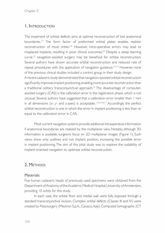
Chapter 51
154
1. intrOductiOn
The treatment of orbital defects aims at optimal reconstruction of lost anatomical boundaries.1-4 The form factor of preformed orbital plates enables realistic reconstruction of most orbits.5-8 However, intra-operative errors may lead to misplaced implants, resulting in poor clinical outcomes.2,9 Despite a steep learning curve,10 navigation-assisted surgery may be beneficial for orbital reconstruction. Several authors have shown accurate orbital reconstruction and reduced rate of repeat procedures with the application of navigation guidance.1,9-14 However, none of the previous clinical studies included a control group in their study design. A recent cadaveric study demonstrated that navigation-assisted orbital reconstruction significantly improves implant positioning, enabling more accurate reconstruction than a traditional solitary transconjunctival approach.15 The disadvantage of computer-assisted surgery (CAS) is the calibration error in the registration phase, which is not unusual. Several authors have suggested that a calibration error smaller than 1 mm in all dimensions (x-, y- and z-axes) is acceptable.1,12,14,16,17 Accordingly, the perfect orbital reconstruction is one in which the error in implant positioning is less than or equal to the calibration error in CAS.
Most current navigation systems provide additional intraoperative information if anatomical boundaries are realized by the multiplanar view. Notably, although 3D information is available, surgeons focus on 2D multiplanar images (Figure 1). Such views show only outlines and not implant position, increasing the possible error in implant positioning. The aim of this pilot study was to explore the suitability of implant-oriented navigation to optimize orbital reconstruction.
2. MethOds
MaterialsFive human cadaveric heads of previously used specimens were obtained from the Department of Anatomy of the Academic Medical Hospital, University of Amsterdam, providing 10 orbits for this study.
In each case, the orbital floor and medial wall were fully exposed through a standard transconjunctival incision. Complex orbital defects (Classes III and IV) were created by Piezosurgery (Mectron S.p.A., Carasco, Italy). Computed tomographic (CT
39372 Dubois, Leander.indd 154 04-03-16 10:19
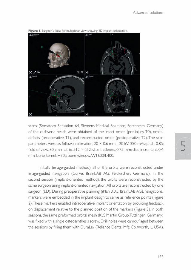
Advanced solutions
155
51
Figure 1. Surgeon’s focus for multiplanar view showing 2D implant orientation.
scans (Somatom Sensation 64, Siemens Medical Solutions, Forchheim, Germany) of the cadaveric heads were obtained of the intact orbits (pre-injury, T0), orbital defects (preoperative, T1), and reconstructed orbits (postoperative, T2). The scan parameters were as follows: collimation, 20 × 0.6 mm; 120 kV; 350 mAs; pitch, 0.85; field of view, 30 cm; matrix, 512 × 512; slice thickness, 0.75 mm; slice increment, 0.4 mm; bone kernel, H70s; bone window, W1600/L400.
Initially (image-guided method), all of the orbits were reconstructed under image-guided navigation (Curve, BrainLAB AG, Feldkirchen, Germany). In the second session (implant-oriented method), the orbits were reconstructed by the same surgeon using implant-oriented navigation. All orbits are reconstructed by one surgeon (LD). During preoperative planning (iPlan 3.0.5, BrainLAB AG), navigational markers were embedded in the implant design to serve as reference points (Figure 2). These markers enabled intraoperative implant orientation by providing feedback on displacement relative to the planned position of the markers (Figure 3). In both sessions, the same preformed orbital mesh (KLS Martin Group, Tuttlingen, Germany) was fixed with a single osteosynthesis screw. Drill holes were camouflaged between the sessions by filling them with DuraLay (Reliance Dental Mfg. Co, Worth, IL, USA).
39372 Dubois, Leander.indd 155 04-03-16 10:19
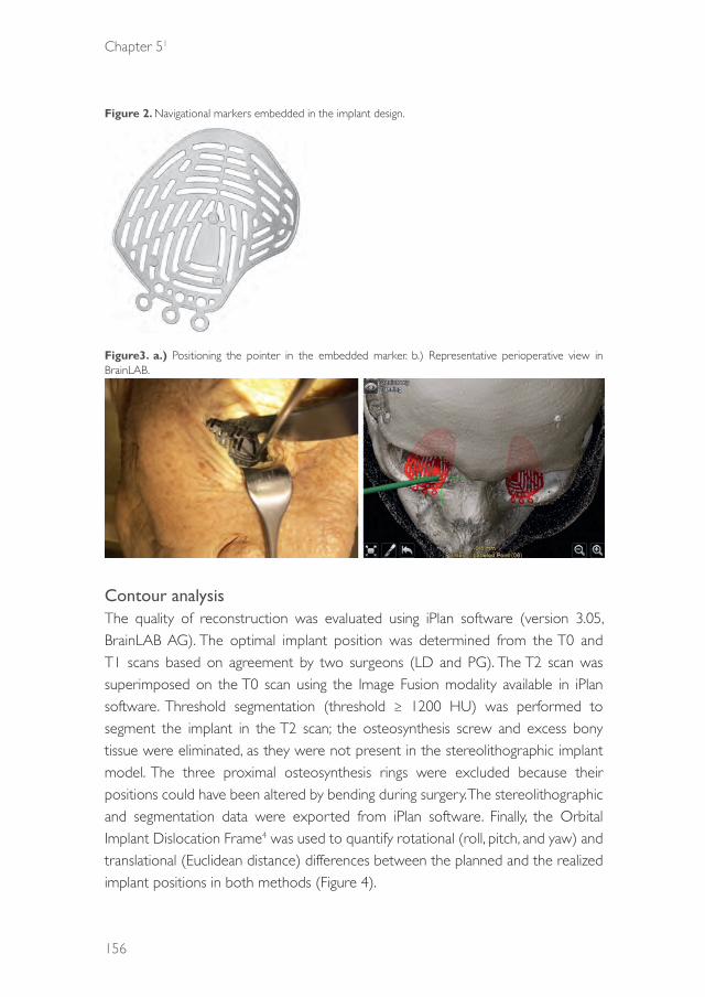
Chapter 51
156
Figure 2. Navigational markers embedded in the implant design.
Figure3. a.) Positioning the pointer in the embedded marker. b.) Representative perioperative view in BrainLAB.
Contour analysisThe quality of reconstruction was evaluated using iPlan software (version 3.05, BrainLAB AG). The optimal implant position was determined from the T0 and T1 scans based on agreement by two surgeons (LD and PG). The T2 scan was superimposed on the T0 scan using the Image Fusion modality available in iPlan software. Threshold segmentation (threshold ≥ 1200 HU) was performed to segment the implant in the T2 scan; the osteosynthesis screw and excess bony tissue were eliminated, as they were not present in the stereolithographic implant model. The three proximal osteosynthesis rings were excluded because their positions could have been altered by bending during surgery. The stereolithographic and segmentation data were exported from iPlan software. Finally, the Orbital Implant Dislocation Frame4 was used to quantify rotational (roll, pitch, and yaw) and translational (Euclidean distance) differences between the planned and the realized implant positions in both methods (Figure 4).
39372 Dubois, Leander.indd 156 04-03-16 10:19

Advanced solutions
157
51
Figure 4. Degrees of freedom (Schreurs et al., 2015) in translation and rotation.
Statistical analysesPaired t-tests were used for comparisons between the conventional image-guided and the implant-oriented methods. Statistical analysis was performed in IBM SPSS Statistics for Macintosh (version 22.0; IBM Corp., Armonk, NY, USA). Statistical significance was defined as P< 0.05.
3. results
The positioning of the implants was significantly (P< 0.05) improved (translation and yaw) by the implant-oriented method compared to the conventional navigation (Table 1). The average translation between the planned and realized position was calculated by 3D orientation and was compared with the commonly used multiplanar distance using the following formula: √(x2 + y2+ z2). This calculation yielded an average distance of 0.76 mm with a standard deviation of 0.2 mm for the implant-oriented method in the multiplanar view.
39372 Dubois, Leander.indd 157 04-03-16 10:19
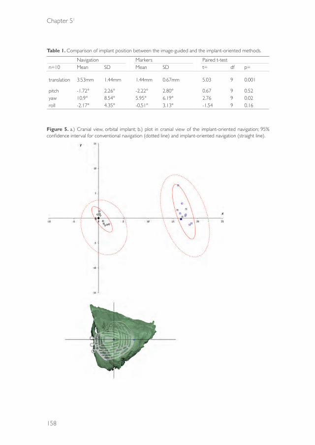
Chapter 51
158
Table 1. Comparison of implant position between the image-guided and the implant-oriented methods.
Navigation Markers Paired t-testn=10 Mean SD Mean SD t= df p=
translation 3.53mm 1.44mm 1.44mm 0.67mm 5.03 9 0.001
pitch -1.72° 2.26° -2.22° 2.80° 0.67 9 0.52yaw 10.9° 8.54° 5.95° 6.19° 2.76 9 0.02roll -2.17° 4.35° -0,51° 3.13° -1.54 9 0.16
Figure 5. a.) Cranial view, orbital implant; b.) plot in cranial view of the implant-oriented navigation; 95% confidence interval for conventional navigation (dotted line) and implant-oriented navigation (straight line).
39372 Dubois, Leander.indd 158 04-03-16 10:19

Advanced solutions
159
51
Figure 6. a.) Frontal view, orbital implant; b.) plot in frontal view of the implant-oriented navigation; 95% confidence interval for conventional navigation (dotted line) and implant-oriented navigation (straight line).
The consistency of the methods is shown in the plots in Figures 5 and 6. The 95% confidence interval, marked as red line (conventional navigation) and red dotted line (implant-oriented navigation), was significantly smaller for the implant-oriented navigation.
By using navigation markers, the yaw was controlled even in cases with medial wall involvement (Table 2). The complexity of the orbital defect (Class III vs. IV) was not related to increased displacement (both rotation and translation) of the implants (Table 3).
39372 Dubois, Leander.indd 159 04-03-16 10:19

Chapter 51
160
Table 2. Comparison of implant position between Class III and Class IV orbital defects in the image-guided method.
no medial wall# medial wall #Mean SD Mean SD p
translation 1.40 0.70 1.46 0.71 0.95
Pitch -2.27 1.68 -2.17 3.53 0.16Yaw 1.82 3.64 8.70 6.19 0.36Roll .73 3.71 .19 2.47 0.10
Table 3. Comparison of implant position between Class III and Class IV orbital defects in the implant-oriented method.
Class 3 Class 4Mean SD Mean SD p
translation 1.41 .73 1.47 .66 0.43
Pitch -3.46 2.08 -.35 2.94 0.37Yaw 4.82 5.28 7.63 7.87 0.59Roll .43 3.34 .63 3.25 0.98
4. discussiOn
Navigation-assisted facial reconstruction is an advancing technology.3,10,11,13-15,16,18,19 In navigation-assistedsurgery, it will take an experienced team only 5–10 min to set up a navigation system. However, additional time is needed for intraoperative imaging (10–20 min) and verification of results. Because of the inherent navigation and calibration error of 1 to 2 mm,10,20 which has only slightly decreased over the last 20 years17 intraoperative imaging is still advised.21 Ideally, consistent and predictable implant placement would make intraoperative imaging unnecessary.
A navigation system should inform the surgeon about the real-time 3D implant position and illustrate in 3D where the implant needs to be placed.19 In the design of patient-specific implants (PSI) adjustments can be made to optimize the individual fit.19,22 With standardized preformed orbital implants, the surgeon can create true-to-origin reconstructions in most orbits3,5-7 if the implant is positioned correctly. However, in more complex orbital defects (class III-IV), preshaped intra-orbital implants have a certain degree of translational and rotational freedom, which can result in suboptimal implant placement, even in the case of navigation as shown by our group in a previous cadaver study.15 Using navigational markers for implant orientation, the surgeon is able
39372 Dubois, Leander.indd 160 04-03-16 10:19

Advanced solutions
161
51
to focus on the actual position of the implant. If the preformed implant is positioned as accurate as possible according to the preoperative planned position, the navigation pointer is used to control the final position by labelling the applied markers. Using this technique a more exact intra-operative positioning of the implant material can be achieved. This study showed that implant-oriented navigation offers the surgeon all of the required information with direct feedback and reduced operator error. The navigation markers help the surgeon to reconstruct an optimal orbit form, with implant displacements smaller than 1 mm in multiplanar views. The small standard deviation indicates that the method provides a more consistent result than image-guided navigation without markers. A previous study showed that navigation-assisted surgery decreases the most common implant rotations (roll and yaw). If the medial wall is involved, yaw of the implant is the most difficult rotation to control. By using navigational markers, yaw was significantly decreased in this study. Despite the small sample size, the high significance indicates that implant-oriented navigation is a fail-safe method and should thus be the preferred method of navigation in patients with complex defects with involvement of the medial wall.
In implant-oriented navigation, an assisting person in the operating room plays an important role in providing information on marker displacement to the operating surgeon. Slight movements when the surgeon’s focus shifts from the operative site to the navigation screen may affect implant or pointer position and, in turn, influence implant placement. Improvement of the feedback software by sound-guided or visual implant positioning may increase the versatility of this method.
5. cOnclusiOn
Navigation-assisted surgery improves the quality of orbital reconstruction, but it can be further advanced by using navigational markers in the implant design for direct feedback on 3D orientation of implant position. This minimal modification of the preformed mesh plates will help the surgeon to optimize orbital reconstruction.
ACKNOWLEDGEMENTSThe authors would like to thank the KLS Martin Group (Tuttlingen, Germany) for the implants, BrainLAB (Feldkirchen, Germany) for use of the Curve, and Petra Habets and Eric Lichtenberg from the Department of Anatomy, Academic Medical
39372 Dubois, Leander.indd 161 04-03-16 10:19

Chapter 51
162
Centre of Amsterdam and Nick Lobe and Ludo Beenen from the Department of Radiology, Academic Medical Centre of Amsterdam for assistance and support in the cadaveric study.
Funding:This study was supported by the KLS Martin Group (Tuttlingen, Germany) and BrainLAB AG (Feldkirchen, Germany). All orbital implants for this study were donated and their stereolithographic files provided by KLS Martin. The navigation equipment suitable for cadaver experiments was provided by BrainLAB AG. Both organizations had no involvement in the study design, collection and interpretation of data, writing of the manuscript, and/or decision to submit the manuscript for publication.
39372 Dubois, Leander.indd 162 04-03-16 10:19

Advanced solutions
163
51
references
1. Essig H, Dressel L, Rana M, Rana M, Kokemueller H, Ruecker M, Gellrich NC. Precision of posttraumatic primary orbital reconstruction using individually bent titanium mesh with and without navigation: a retrospective study. Head Face Med. 2013: 9:18.
2. Dubois L, Steenen SA, Gooris PJJ, Mourits MP, Becking AG. Controversies in orbital reconstruction. I. Defect-driven orbital reconstruction: a systematic review. Int J Oral Maxillofac Surg. 2015: 44: 308-15.
3. Dubois L, Steenen SA, Gooris PJJ, Bos RRM, Becking AG. Controversies in orbital reconstruction. III. Biomaterials for orbital reconstruction: a review with clinical recommendations. Int J Oral Maxillofac Surg. 2015. (Epub ahead of print)
4. Schreurs R, Dubois L, Becking AG, Maal TJJ: Measuring predictability in orbital reconstruction: quantitative assessment of orbital implant position. PLOS ONE (unpublished results).
5. Metzger MC, Hohlweg-Majert B, Schon R, Teschner M, Gellrich NC, Schmelzeisen R, Gutwald R. Verification of clinical precision after computer-aided reconstruction in craniomaxillofacial surgery. Oral Surg Oral Med Oral Pathol Oral Radiol Endod. 2007: 104: 1-10.
6. Andrades P, Hernandez D, Falguera MI, Millan JM, Heredero S, Gutierrez R, Sánchez-Aniceto G: Degrees of tolerance in post-traumatic orbital volume correction: the role of prefabricated mesh. J Oral Maxillofac Surg. 2009: 67: 2404-11.
7. Strong EB, Fuller SC, Wiley DF, Zumbansen J, Wilson MD, Metzger MC. Preformed vs intraoperative bending of titanium mesh for orbital reconstruction. Otolaryngol Head Neck Surg. 2013: 149: 60-6.
8. Dubois L, Jansen J, Schreurs R, Saeed P, Beenen, L, Gooris PJJ, Maal TJJ, Becking AG. Predictability in orbital reconstruction: a human cadaver study. Part I: Endoscopic-assisted orbital reconstruction. J Craniomaxillofac Surg. 2015 (Epub ahead of print).
9. Dubois L, Steenen SA, Gooris PJJ, Mourits MP, Becking AG. Controversies in orbital reconstruction. II. Timing of post-traumatic orbital reconstruction: a systematic review. Int J Oral Maxillofac Surg. 2015: 44:433-40.
10. Cai EZ, Koh YP, Hing ECH, Low JR, Shen JY, Wong HC, Gangadhara S, Lim TC. Computer-assisted navigational surgery improves outcomes in orbital reconstructive surgery. J Craniofac Surg. 2012: 23: 1567-73.
11. Collyer J. Stereotactic navigation in oral and maxillofacial surgery. Br J Oral Maxillofac Surg. 2010: 48: 79-83.
12. Markiewicz MR, Dierks EJ, Bell RB. Does intraoperative navigation restore orbital dimensions in traumatic and post-ablative defects? J Craniomaxillofac Surg. 2012: 40: 142-8.
13. Zhang S, Gui H, Lin Y, Shen G, Xu B. Navigation-guided correction of midfacial post-traumatic deformities (Shanghai experience with 40 cases). J Oral Maxillofac Surg. 2012: 70: 1426-33.
14. Yu H, Shen SG, Wang X, Zhang L, Zhang S. The indication and application of computer-assisted navigation in oral and maxillofacial surgery – Shanghai’s experience based on 104 cases. J Craniomaxillofac Surg. 2013: 41: 770-4.
15. Dubois L, Schreurs R, Jansen J, Essig H, Gooris PJJ, Maal TJJ, Becking AG. Predictability in orbital reconstruction: a human cadaver study. Part I: Navigation-assisted orbital reconstruction. J Craniomaxillofac Surg. 2015 (Epub ahead of print)
16. Markiewicz MR, Dierks EJ, Potter BE, Bell RB: Reliability of intraoperative navigation in restoring normal orbital dimensions. J Oral Maxillofac Surg. 2011: 69: 2833-40.
17. Widmann G, Zangerl A, Schullian P, Fasser M, Puelacher W, Bale R. Do image modality and registration method influence the accuracy of craniofacial navigation? J Oral Maxillofac Surg. 2012: 70: 2165-73.
18. Bell RB, Markiewicz MR. Computer-assisted planning, stereolithographic modeling, and intraoperative navigation for complex orbital reconstruction: a descriptive study in a preliminary cohort. J Oral Maxillofac Surg. 2009: 67: 2559-70.
19. Rana M, Gellrich MM, Gellrich NC. Customised reconstruction of the orbital wall and engineering of selective laser melting (SLM) core implants. Br J Oral Maxillofac Surg. 2015: 53: 208-9.
20. Lee H, Jilani M, Frohman L, Baker S. CT of orbital trauma. Emerg Radiol. 2004: 10: 168-72.
21. Wilde F, Schramm A. Intraoperative imaging in orbital and midface reconstruction. Facial Plast Surg. 2014: 30: 545-53.
22. Gander T, Essig H, Metzler P,Lindhorst D, Dubois L, Rücker M, Schumann P. Patient specific implants (PSI) in reconstruction of orbital floor and wall fractures. J Craniomaxillofac Surg. 2015: 43: 126-30.
39372 Dubois, Leander.indd 163 04-03-16 10:19

39372 Dubois, Leander.indd 164 04-03-16 10:19

CHAPTER 52
Patient Specifi c Implants (PSIs)
This chapter is an edited version of the manuscript: Gander T, Essig H, Metzler P, Lindhorst D, Dubois L, Rücker M, Schumann P:
Patient specifi c implants (PSI) in reconstruction of orbital fl oor and wall fractures. J Craniomaxillofac Surg 2015: 43: 126 -30.
39372 Dubois, Leander.indd 165 04-03-16 10:19

Chapter 52
166
intrOductiOn
The orbital wall and floor are common sites of facial bone fracture and may cause serious functional impairment.1 Numerous cases of reconstructive implant use have been described in the literature.2,3 The repair of orbital wall and floor fractures is difficult due to the complexity of the anatomical region involved, and the limited intraoperative view. Meticulous imaging, and clinical examination, is indispensable for treatment planning, in order to restore orbital volume and shape. Ill-fitting implants and inaccurate surgical techniques may lead to visual disturbances and unaesthetic results.4 Computer assisted three-dimensional (3D) treatment planning, and ready-to-use, individual titanium mesh implants, are routinely applied to achieve stable reconstruction and adequate postoperative results.5,6 Contemporary standardized titanium meshes are manually adjusted to fit individual patients’ polyamide models.7 We present a new approach employing customized, ready to use, patient- specific titanium implants (KLS Martin, Group, Germany), suitable for daily use. These easily manufactured and implemented, ready-made patient specific implants (PSI) allow for a more cost- and time-effective operating procedure.
Material and MethOds Patients who underwent operations for orbital wall and/or floor fractures, between February 2014 and June 2014, were recruited, irrespective of their gender, age, trauma type or the presence of concomitant injuries. Informed consent was provided by all patients. Preoperative CT-scan data, with a slice thickness of 0.3 mm, were processed using the iPlan software package (ver. 3.0.5, Brainlab, Feldkirchen, Germany) to generate a 3D reconstruction of the affected orbit, using the mirrored non-affected orbit as a template. Correction of minor asymmetry was effected via the 3D smart shaper function. Accurate use of the 3D smart shaper is a key step in the planning process, and must be performed with caution to avoid discrepancies during subsequent implant placement (Figures 1-2). The parameters of the patient-specific implant are outlined, and three landmarks are positioned on the planned implants to allow for rapid and effective 3D control of the implant’s position (Figures 3-5). Each planning step can be easily performed by any surgeon: no specialist, a priori knowledge of the software is beneficial.
39372 Dubois, Leander.indd 166 04-03-16 10:19

Advanced solutions
167
52
Figure 1 . Placement of the smart shaper in the required area
Figure 2. Adaption of the selected area with the smart shaper
Figure 3 . Determination of the prospective implant’s extent
39372 Dubois, Leander.indd 167 04-03-16 10:19
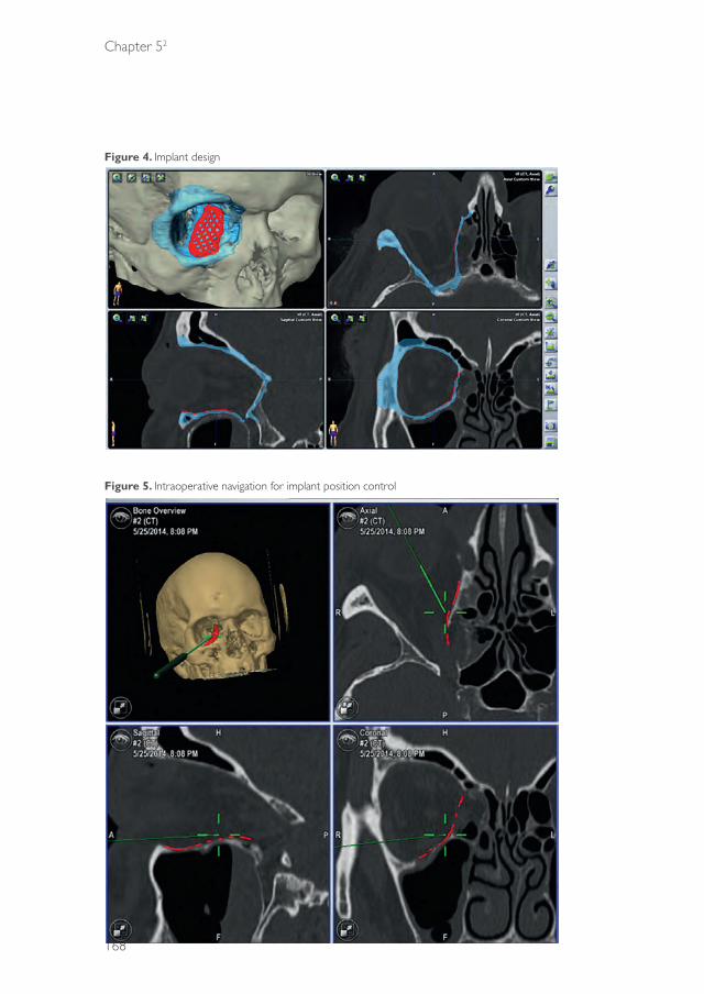
Chapter 52
168
Figure 4. Implant design
Figure 5. Intraoperative navigation for implant position control
39372 Dubois, Leander.indd 168 04-03-16 10:19

Advanced solutions
169
52
Precise transfer of the 3D coordinates of the implant, from iPlan 3.0.5 to the manufacturing software (KLS Martin), represents an essential precondition of intraoperative control. STL data are then exported and approved for the purposes of implant manufacture. This procedure obviates the need for time-consuming integration of the dataset within the manufacturing software. Circumferential implant cushions should be created, although laser-sintered, individually manufactured implants (with a thickness of 0.3 mm) exhibit greater stiffness compared with manually adjusted titanium meshes and therefore allow for minor dimensioning of the implant.8
Overextended implants can easily be reduced in extent by pincers and manual adjustment is still possible, although to a lesser degree compared with standardized implants. The need of manual adjustment should be avoided by meticulous preoperative implant planning.
Individually manufactured titanium implants are positioned using a retroseptal, transconjunctival approach (Figure 6). Application of a polydioxanon foil, which may improve the surgeon’s view by preventing fatty tissues from encroaching on to the operative site, was utilized in certain cases. The polydioxanon foil is removed following placement of the implant and prior to wound closure. Dental arch splints in dentulous patients, and mini screws placed in the calvarian bones of edentulous patients, were used as registration markers. Postoperative CT-scans were performed to assess implant position. Quality management was effected by importation and superimposition of the postoperative dataset (Figure 7). All patients underwent a pre- and post-operative ophthalmological examination.
results
A total 12 patients were included. All patients underwent reconstruction of the orbital wall or orbital floor, via PSIs using intraoperative navigation, and in accordance with a transconjunctival, post-septal approach. In eight patients indication for surgery was imposed due to diplopia. Four patients underwent orbital reconstruction owing to profound defects or enophthalmos. The male to female ratio of the sample was 11:1, with a mean age of 53 years (range: 29–78 years). Major causes of orbital floor or wall fractures included industrial accidents and falls (Table 1).
39372 Dubois, Leander.indd 169 04-03-16 10:19

Chapter 52
170
Figure 6. Transconjunctival, post-septal PSI placement
Figure 7. Superimposition of the preoperative planning position upon the postoperative PSI position
A C C E P T E
In seven patients, dental splints were applied for intraoperative navigation purposes, in addition to dental cusps. In four patients navigation screws were employed in the calvaria, for intraoperative registration and navigation. CT scans were performed preoperatively, and the registration tools were introduced.
39372 Dubois, Leander.indd 170 04-03-16 10:19
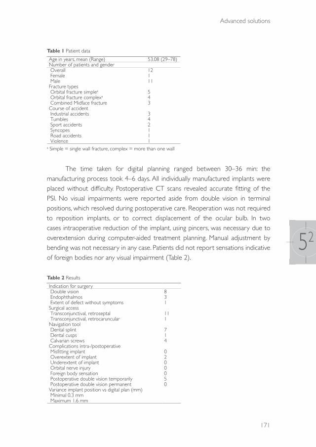
Advanced solutions
171
52
Table 1 Patient data
Age in years, mean (Range) 53.08 (29–78)Number of patients and gender Overall 12 Female 1 Male 11Fracture types Orbital fracture simplea 5 Orbital fracture complexa 4 Combined Midface fracture 3Course of accident Industrial accidents 3 Tumbles 4 Sport accidents 2 Syncopes 1 Road accidents 1 Violence 1
a Simple = single wall fracture, complex = more than one wall
The time taken for digital planning ranged between 30–36 min: the manufacturing process took 4–6 days. All individually manufactured implants were placed without difficulty. Postoperative CT scans revealed accurate fitting of the PSI. No visual impairments were reported aside from double vision in terminal positions, which resolved during postoperative care. Reoperation was not required to reposition implants, or to correct displacement of the ocular bulb. In two cases intraoperative reduction of the implant, using pincers, was necessary due to overextension during computer-aided treatment planning. Manual adjustment by bending was not necessary in any case. Patients did not report sensations indicative of foreign bodies nor any visual impairment (Table 2).
Table 2 Results
Indication for surgery Double vision 8 Endophthalmos 3 Extent of defect without symptoms 1Surgical access Transconjunctival, retroseptal 11 Transconjunctival, retrocaruncular 1Navigation tool Dental splint 7 Dental cusps 1 Calvarian screws 4Complications intra-/postoperative Misfitting implant 0 Overextent of implant 2 Underextent of implant 0 Orbital nerve injury 0 Foreign body sensation 0 Postoperative double vision temporarily 5 Postoperative double vision permanent 0Variance implant position vs digital plan (mm) Minimal 0.3 mm Maximum 1.6 mm
39372 Dubois, Leander.indd 171 04-03-16 10:19

Chapter 52
172
discussiOn
Orbital floor and wall fractures represent common skeletal, facial injuries:9,10 diplopia, enophthalmos and infra- orbital and optical nerve injuries are potential complications of orbital floor and wall fracture surgery.11 Safe, rapid, reproducible and precise procedures are required to avoid such issues. Computer-assisted surgery represents a key step towards safer practice, and has become a standard technique during the past few years, allowing for virtual surgery planning, simulation and intraoperative control.5,6 New surgical methods, and improved implant designs and materials, have been introduced incrementally, in some cases with great success.12-15 PSIs allow for the precise reconstruction of orbital fractures by means of a complete digital workflow. Manually bent titanium mesh implants will become less important. A precondition of the digital workflow is the transfer of the planning software’s coordinates system into the manufacturing software, to avoid time-consuming and erroneous positioning of the virtual implant.
Correct positioning of the PSI can be verified using intraoperative navigation, to support the three virtually planned indentations incorporated in the manufactured implant.6 The three planned indentations and their stored coordinates also serve as measuring points during the virtual planning process, thereby improving overall accuracy. The implant is digitally planned by the surgeon, with a focus on its extent and the position of the three landmarks. The coordinate system of the digital plan must be conserved during the entirety of the manufacturing process, to allow for accurate superimposition of the pre- and postoperative implant positions. Although PSIs are dimensionally more stable compared with manually bent titanium implants, a circumferential cushion is nonetheless recommended. Furthermore, stiffness in PSIs prevents implant deformation during placement, but still allows for minor, intraoperative corrections by pincers. Due to the increased stiffness of laser-sintered PSIs compared with conventional titanium meshes, precise preoperative planning is required to avoid interference during insertion of the PSI.
Routinely incorporating postoperative results into preoperative virtual planning activities, and assessing implant positioning via superimposition, both represent ground-breaking advances in medical quality control.
39372 Dubois, Leander.indd 172 04-03-16 10:19

Advanced solutions
173
52
cOnclusiOn
PSIs simplify the reconstruction of orbital floor and wall fractures, and should be considered a more accurate alternative to manually bent titanium mesh implants. Automation allows for the application of safe, time-effective, daily procedures; accordingly, its use should be encouraged. Implant planning can be easily undertaken by any surgeon, and does not require specialized, software-specific knowledge.
As previously stated by the World Health Organization, PSIs should play a key role in daily routines, and furthermore should replace conventional implants by 2020. PSI for the reconstruction of orbital floor and wall fractures is now readily available.
More patients will be included in this study and long-term results will be gathered in the future to allow more funded statements.
Conflict of Interest Statement All authors disclose any financial and personal relationships with other people or organisations that could inappropriately influence (bias) this work.
39372 Dubois, Leander.indd 173 04-03-16 10:19
Chapter 52
174
references
1. Shin JW, Lim JS, Yoo G, Byeon JH. An analysis of pure blowout fractures and associated ocular symptoms. J Craniofac Surg. 2013: 24: 703-7.
2. Strong EB, Fuller SC, Wiley DF, Zumbansen J, Wilson MD, Metzger MC. Preformed vs intraoperative bending of titanium mesh for orbital reconstruction. Otolaryngol Head Neck Surg. 2013: 149: 60-6.
3. Gerressen M, Gillessen S, Riediger D, Hölzle F, Modabber A, Ghassemi A. Radiologic and facial morphologic long-term results in treatment of orbital floor fracture with flexible absorbable alloplastic material. J Oral Maxillofac Surg. 2012: 70: 2375-85.
4. Ewers R, Schicho K, Undt G, Wanschitz F, Truppe M, Seemann R, Wagner A. Basic research and 12 years of clinical experience in computer-assisted navigation technology: a review. Int J Oral Maxillofac Surg. 2005: 34: 1-8.
5. Essig H, Dressel L, Rana M, Kokemueller H, Ruecker M, Gellrich NC. Precision of posttraumatic primary orbital reconstruction using individually bent titanium mesh with and without navigation: a retrospective study. Head Face Med. 2013: 9: 18.
6. Schramm A, Suarez-Cunqueiro MM, Rücker M, Kokemueller H, Bormann KH, Metzger MC, Gellrich NC. Computer-assisted therapy in orbital and mid-facial reconstructions. Int J Med Robot. 2009: 5: 111-24.
7. Kozakiewicz M, Szymor P. Comparison of pre-bent titanium mesh versus polyethylene implants in patient specific orbital reconstructions. Head Face Med. 2013: 29: 32.
8. Ibrahim D, Broilo TL, Heitz C, de Oliveira MG, de Oliveira HW, Nobre SM, Dos Santos Filho JH, Silva DN. Dimensional error of selective laser sintering, three-dimensional printing and PolyJet models in the reproduction of mandibular anatomy. J Craniomaxillofac Surg. 2009: 37: 167-73.
9. Rosado P, de Vicente JC. Retrospective analysis of 314 orbital fractures. Oral Surg Oral Med Oral Pathol Oral Radiol. 2012: 113: 168-71.
10. Dimitroulis G, Eyre J. A 7-year review of maxillofacial trauma in a central London hospital. Br Dent J. 1991: 20: 300-2.
11. Brucoli M, Arcuri F, Cavenaghi R, Benech A. Analysis of complications after surgical repair of orbital fractures. J Craniofac Surg. 2011: 22: 1387-90.
12. Gierloff M, Seeck NG, Springer I, Becker S, Kandzia C, Wiltfang J. Orbital floor reconstruction with resorbable polydioxanone implants. J Craniofac Surg. 2012: 23: 161-4.
13. Avashia YJ, Sastry A, Fan KL, Mir HS, Thaller SR. Materials used for reconstruction after orbital floor fracture. J Craniofac Surg. 2012: 23: 1991-7.
14. Ciprandi MT, Primo BT, Gassen HT, Closs LQ, Hernandez PA, Silva AN Jr. Calcium phosphate cement in orbital reconstructions. J Craniofac Surg. 2012: 23: 145-8.
15. Schumann P, Lindhorst D, Wagner ME, Schramm A, Gellrich NC, Rücker M: Perspectives on resorbable osteosynthesis materials in craniomaxillofacial surgery. Pathobiology. 2013: 80: 211-17.
39372 Dubois, Leander.indd 174 04-03-16 10:19

39372 Dubois, Leander.indd 175 04-03-16 10:19

39372 Dubois, Leander.indd 176 04-03-16 10:19

CHAPTER 6General discussion
39372 Dubois, Leander.indd 177 04-03-16 10:19

Chapter 6
178
general discussiOn
Orbital wall reconstruction can be a complex procedure with variable results. For improving predictability it is important to understand the common errors in diagnostics, work-up and execution. Optimal placement of an orbital implant is the first and probably the most controllable step in orbital reconstruction and may be regarded as fundamental for restoring a traumatized orbit, but this is not the only factor for an optimal clinical outcome.
In this thesis the following topics were addressed:- What are the main controversies in orbital reconstruction and what
evidence-based guidelines are currently available?- How reliable is a surgeon’s visual appraisal for the diagnosis of orbital
fractures? - Which additional tools, such as endoscopic assistance and navigational
support, are beneficial for orbital reconstruction?- Can the accuracy of orbital implant placement be improved?
ControversiesAfter three reviews it can be concluded that the evidence to support current standard treatment of orbital reconstruction is poor. The indications and timing of treatment remain controversial, although most authors agree, based on expert opinions and retrospective studies, on the indications for immediate reconstruction. Severe globe dislocations with visual threatening emergencies, evident entrapment of ocular muscle and/or white-eye blow-out (almost exclusively in paediatric patients) are believed to be emergency indications. Although CT imaging is regarded as the gold standard for diagnosing orbital trauma, evaluation of muscle entrapment on CT images has been shown to be non-conclusive in almost 50% of the cases.1,2 The main reasons for this are poor diagnosis of the trapdoor mechanism by radiologists and the relative weakness of CT in imaging soft tissues.1-3 Ultimately, a combination of clinical examination and radiological information is required for an optimal diagnosis and for treatment planning, even for adult patients.
The focus on true, well-founded indications for optimal timing can be shifted from the indications for early intervention towards the question as to which patients will benefit from delayed repair. Due to the sequellae of acute trauma, such as swelling,
39372 Dubois, Leander.indd 178 04-03-16 10:19

General discussion
179
6
true enophthalmos (necessitating early surgery) cannot be reliably identified until two weeks have passed and diplopia may resolve spontaneously .4-7
Although in the literature a fracture size of >2 cm2 or a fracture of >50% of the orbital floor are commonly used as indications justifying reconstruction,8 to date there is no exact knowledge regarding which orbital wall fracture, in terms of size and location, needs reconstruction. This thesis is intended to produce a protocol for complexity-driven orbital reconstruction. A key issue in this matter is to define the line between undertreatment and overtreatment.
A conservative approach, comparable to the Putterman concept7 in the 1970s, may reduce the indications for (early) surgical intervention, but there is still no estimate of the reduction percentages. However, from prospective studies utilizing a well-defined clinical decision algorithm, treatment protocols and CT data, the extent of reduction may be estimated.
When there are true indications, such as the entrapment of orbital contents with an absolute motility restriction, or an early significant enopthalmos or hypoglobus (>2 mm), early reconstruction is clearly justified. But in other, more doubtful indications an expectative policy is recommended. If the motility of the eye improves significantly over a period of 10–14 days, surgery may not be indicated for which favourable results are suggested in the literature.4-6 Following these recommendations means that the clinical findings in the patient overrule the interpretation of the CT images. The clinical outcome of each patient treated with this protocol provides accurate feedback for reconstructive decisions.
There is no strong evidence that a delayed reconstruction will affect the outcome of orbital reconstruction.9,10 Indeed, delaying surgery may result in an advantage, since the swelling will have reduced. The additional preparation time also facilitates computer-assisted planning, navigation-assisted surgery, manufacturing of a patient-specific implant or referral to a specialized centre.
Visual appraisalThe diagnostic process is the first pillar for optimal treatment of orbital fractures. Accurate estimation of the actual size of orbital defects is fundamental for clinical decision-making and the success of a complexity-driven treatment protocol. The
39372 Dubois, Leander.indd 179 04-03-16 10:19

Chapter 6
180
study on visual appraisal (Chapter 3) shows that most surgeons are unable to determine accurately and consistently fracture length, width and surface without the help of advanced diagnostic tools. Direct intraoperative visualization and surgical experience are of no significant value in the estimation of fracture size and complexity, and additional endoscopy provides no further advantages.
Measurements on CT images are the best diagnostic modality available in daily practice for estimation of the fracture size and complexity.11 Width measurements have been shown to be reliable. Length measurements can be further improved with adjustable multiplanar views, which are available in some software packages. Modification of orientation by axis adjustments could improve measurement of the fracture length.
This current study shows that estimation of the critical surface of the defect results in serious overestimation (26–86%). The Burnstine criteria (fracture >2 cm2 or >50% of orbital floor) most commonly used as an indication for orbital reconstruction predetermine the risk of surgical “overtreatment”. An integrated formula as described by Goggin12 aids in calculating the actual defect size with a smaller standard error. Smart software tools are expected to reliably perform automatic segmentation and measure the critical size of the defect. In addition, segmentation and mirroring software will improve further diagnosis.13
Conventional reconstructionConventional orbital reconstruction can lead to unpredictable results and the reasons for this can be difficult to identify. The first goal is to acquire knowledge of what is actually being done and how to improve results. The surgeon’s experience is enriched by a combination of real-time and postoperative feedback from imaging modalities, and subsequently by the clinical outcome. However, if the results are only evaluated clinically, the refinement of a technique is more complex and may take years of experience. With the use of innovative diagnostic tools for preoperative planning14 and real-time feedback from intraoperative imaging, the surgeon is able to visualize actual results, and can verify whether the postoperative outcome is consistent with the optimal preoperative plan. All these modern tools allow visualization and objective measurement of the surgical result. The primary focus for orbital reconstruction is true-to-original repair of the orbit. To reach this goal and deliver predictable surgical results, every single step in a reconstructive procedure needs to be controlled. The
39372 Dubois, Leander.indd 180 04-03-16 10:19
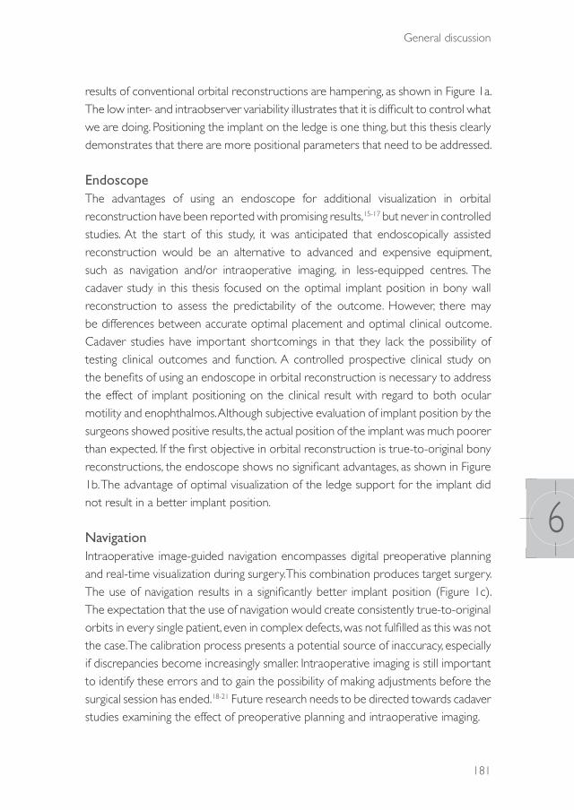
General discussion
181
6
results of conventional orbital reconstructions are hampering, as shown in Figure 1a. The low inter- and intraobserver variability illustrates that it is difficult to control what we are doing. Positioning the implant on the ledge is one thing, but this thesis clearly demonstrates that there are more positional parameters that need to be addressed.
EndoscopeThe advantages of using an endoscope for additional visualization in orbital reconstruction have been reported with promising results,15-17 but never in controlled studies. At the start of this study, it was anticipated that endoscopically assisted reconstruction would be an alternative to advanced and expensive equipment, such as navigation and/or intraoperative imaging, in less-equipped centres. The cadaver study in this thesis focused on the optimal implant position in bony wall reconstruction to assess the predictability of the outcome. However, there may be differences between accurate optimal placement and optimal clinical outcome. Cadaver studies have important shortcomings in that they lack the possibility of testing clinical outcomes and function. A controlled prospective clinical study on the benefits of using an endoscope in orbital reconstruction is necessary to address the effect of implant positioning on the clinical result with regard to both ocular motility and enophthalmos. Although subjective evaluation of implant position by the surgeons showed positive results, the actual position of the implant was much poorer than expected. If the first objective in orbital reconstruction is true-to-original bony reconstructions, the endoscope shows no significant advantages, as shown in Figure 1b. The advantage of optimal visualization of the ledge support for the implant did not result in a better implant position.
NavigationIntraoperative image-guided navigation encompasses digital preoperative planning and real-time visualization during surgery. This combination produces target surgery. The use of navigation results in a significantly better implant position (Figure 1c). The expectation that the use of navigation would create consistently true-to-original orbits in every single patient, even in complex defects, was not fulfilled as this was not the case. The calibration process presents a potential source of inaccuracy, especially if discrepancies become increasingly smaller. Intraoperative imaging is still important to identify these errors and to gain the possibility of making adjustments before the surgical session has ended.18-21 Future research needs to be directed towards cadaver studies examining the effect of preoperative planning and intraoperative imaging.
39372 Dubois, Leander.indd 181 04-03-16 10:19

Chapter 6
182
Figure 1. Average implant position
a.) Difference between the planned and realized orbital implant position for conventional orbital reconstructions (grey= planned implant position; orange= conventional)
b.) Difference between the planned and realized orbital implant position for endoscopic assisted reconstructions (grey= planned implant position; blue=endosope)
c.) Difference between the planned and realized orbital implant position for navigation assisted reconstructions (grey= planned implant position; red=navigation)
d.) Difference between the planned and realized orbital implant position for object-oriented navigation (grey= planned implant position; purple=implant-oriented navigation)
39372 Dubois, Leander.indd 182 04-03-16 10:19

General discussion
183
6
Other methods of registration need to be explored as well in order to reduce the calibration error. The combination of intraoperative scanning and navigation, as introduced by AIRO (BrainLAB AG, Feldkirchen, Germany), may further reduce these inaccuracies. Improved 3D visualization tools for the surgeon may also be beneficial. In navigation-assisted surgery the surgeon is focusing on the screen in the multiplanar view, in separate views, while positioning the implant towards its ideal placement. The surgeon needs to extract the actual position of the implant from the separate multiplanar views. In the meantime, unplanned rotational or translational movements may have occurred. Adding orientation in a 3D-rendered image, preferably pointer position in relation to the implant, will simplify these actions. In conclusion, navigation assistance has proved to be extremely helpful in orbital reconstruction.
Object oriented navigationIn our opinion there is one essential step missing from image-guided navigation and that is the possibility to track an object visually during positioning. Previous attempts at object-oriented navigation have struggled with object calibration failures.22,23 Stereolithographic models of predefined shapes such as the preformed orbital implants can be easily imported into the planning software. If additional markers were to be embedded in the implant design, this could exclude the need for extra calibration. The pilot study on object-oriented navigation showed that it would be possible to verify the actual implant position accurately and significantly, within the calibration error (1–2 mm). The markers embedded in the implant design allow failsafe true-to-original reconstructions, as shown in Figure 1d. Due to this accuracy, intraoperative imaging may become obsolete. New studies will focus on finding the best position for the markers to increase the predictability of the implant position.
Patient-specific implants (PSI)Malpositioned orbital implants may lead to motility disturbances and aesthetic deformities.19,24 In computer-assisted surgery (CAS) workflows, patient-specific implants can be designed to result in a true-to-original reconstruction by means of a complete digital workflow. The stiffness of laser sintered titanium has increased compared with a bent or pre-bent mesh.19 This stiffness means that meticulous planning is required to avoid interferences during insertion. Although the design is customized so that the implant will fit at its desired position and can therefore be positioned even more accurately, rotational and translational errors may still occur during placement, resulting in malpositioning. It is thought that adding embedded
39372 Dubois, Leander.indd 183 04-03-16 10:19
Chapter 6
184
navigation markers to the PSI design will increase the predictability of the implant position. Further research on this subject has been started.
Nevertheless, in complex secondary reconstructions PSIs are superior to preformed implants, certainly in cases in which anatomical landmarks are missing or have changed due to bone remodelling.
Since time is needed to design and produce patient-specific implants, they are less suitable for cases where early reconstruction is indicated.
Further research is being directed towards semi-adjustable patient-specific implants, which can be adjusted digitally or even intraoperatively to accelerate the preparation time and optimize the workflow of generating a predictable patient-specific solution. These PSIs may be suitable for acute and early indications for orbital reconstruction.
Future perspectivesThe high end of computer-assisted surgery is real-time, object-oriented navigation in combination with robotics. Such usages and achievements have been reported in different situations. Orbital surgery fulfils the requirements for the use of robotics: low volume and high complexity planning and surgery, obstructed intraoperative visualization and extremely high demands for exact positioning of implants.
A second future objective for orbital reconstruction research is directed towards soft-tissue responses to trauma and/or surgery, and the consequent changes in orbital volume. The function and position of the globe does not depend entirely on the accuracy of orbital wall reconstruction but is also influenced by soft-tissue damage and fibrosis. These sequellae are difficult to predict and hard to influence in primary surgery. The fibrous septae and ligaments of the peri-orbit fulfil an important role in supporting the soft tissues.25 Complications may occur in even apparently perfect orbital reconstructions. The disruption of these ligaments, septae and fat is probably responsible for these unpredictabilities. The development of 3D software for visco-elastic soft-tissue response prediction may be an important step for proper evaluation of the alteration in the soft tissues in the orbit. The contents of the orbit and its response to trauma and surgery is the subject of future research at AMC, in order to advance predictability in the restoration of perfect bony anatomy, adequate orbital volume and optimalisation in ocular function.
39372 Dubois, Leander.indd 184 04-03-16 10:19

General discussion
185
6
references
1. Parbhu KC, Galler KE, Li C, Mawn LA. Underestimation of soft tissue entrapment by computed tomography in orbital floor fractures in the pediatric population. Ophthalmology. 2008: 115: 1620-5.
2. Jordan DR, Allen LH, White J, Harvey J, Pashby R, Esmaeli B. Intervention within days for some orbital floor fractures: the white-eyed blowout. Ophthal Plast Reconstr Surg. 1998: 14: 379-90.
3. Wei LA, Durairaj VD. Pediatric orbital floor fractures. J AAPOS. 2011: 15: 173-80. 4. Everhard-Halm YS, Koornneef L, Zonneveld FW. [Conservative therapy frequently indicated in blow-out
fractures of the orbit]. Ned Tijdschr Geneeskd. 1991: 135: 1226-8. 5. Beigi B, Khandwala M, Gupta D. Management of pure orbital floor fractures: a proposed protocol to
prevent unnecessary or early surgery. Orbit. 2014: 33: 336-42. 6. Alhamdani F, Durham J, Greenwood M, Corbett I. Diplopia and ocular motility in orbital blow-out
fractures: 10-year retrospective study. J Craniomaxillofac Surg. 2015: 43: 1010-6. 7. Putterman AM, Stevens T, Urist MJ. Nonsurgical management of blow-out fractures of the orbital floor.
Am J Ophthalmol. 1974: 77: 232-9.8. Burnstine MA. Clinical recommendations for repair of orbital facial fractures. Curr Opin Ophthalmol. 2003:
14: 236-40.9. Scawn RL, Lim LH, Whipple KM, Dolmetsch A, Priel A, Korn B, Kikkawa DO. Outcomes of orbital blow-
out fracture repair performed beyond 6 weeks after injury. Ophthal Plast Reconstr Surg. 2015 (Epub ahead of print)
10. Simon GJ, Syed HM, McCann JD, Goldberg RA. Early versus late repair of orbital blow-out fractures. Ophthalmic Surg Lasers Imaging 2009: 40: 141–8.
11. Schouman T, Courvoisier DS, Imholz B, Van Issum C, Scolozzi P. Computational area measurement of orbital floor fractures: reliability, accuracy and rapidity. Eur J Radiol. 2012: 81: 2251-4.
12. Goggin J, Jupiter DC, Czerwinski M. Simple computed tomography-based calculations of orbital floor fracture defect size are not sufficiently accurate for clinical use. J Oral Maxillofac Surg. 2015: 73: 112-6.
13. Blumer M, Gander T, Kruse Gujer A, Seifert B, Rücker M, Lübbers H-T. Influence of mirrored computed tomograms on decision-making for revising surgically treated orbital floor fractures. J Oral Maxillofac Surg. 2015: 73: 1-9.
14. Jansen J, Schreurs R, Dubois L, et al: Orbital volume analysis: validation of a semi-automatic software segmentation method. Int J Comput Assist Radiol Surg. 2015 (Epub ahead of print)
15. Kakibuchi M, Fukazawa K, Fukuda K, et al. Combination of transconjunctival and endonasal-transantral approach in the repair of blowout fractures involving the orbital floor. Br J Plast Surg. 2004; 57: 37-44.
16. Kwon JH, Kim JG, Moon JH, Cho JH. Clinical analysis of surgical approaches for orbital floor fractures. Arch Facial Plast Surg 2008: 10:21 4.
17. Hundepool AC, Willemsen MAP, Koudstaal MJ, van der Wal KGH. Open reduction versus endoscopically controlled reconstruction of orbital floor fractures: a retrospective analysis. Int J Oral Maxillofac Surg. 2012: 41: 489-93.
18. Schramm A, Suarez-Cunqueiro MM, Rücker M, Kokemueller H, Bormann KH, Metzger MC, Gellrich NC. Computer-assisted therapy in orbital and mid-facial reconstructions. Int J Med Robotics 2009: 5: 111-24
19. Rana M, Chui CHK, Wagner M, Zimmerer R, Rana M. Increasing the accuracy of orbital reconstruction with selective laser-melted patient-specific implants combined with intraoperative navigation. J Oral Maxillofac Surg. 2015: 73: 1113-8.
20. Essig H, Dressel L, Rana M, et al. Precision of posttraumatic primary orbital reconstruction using individually bent titanium mesh with and without navigation: a retrospective study. Head Face Med. 2013: 9: 18.
21. Gellrich N-C, Schramm A, Hammer B, et al. Computer-assisted secondary reconstruction of unilateral posttraumatic orbital deformity. Plast Reconstr Surg. 2002: 110: 1417-29.
22. Helm PA, Eckel TS. Accuracy of registration methods in frameless stereotaxis. Comput Aid Surg. 1998: 3: 51-6.
23. Yu H, Shen SG, Wang X, Zhang L, Zhang S. The indication and application of computer-assisted navigation in oral and maxillofacial surgery-Shanghai’s experience based on 104 cases. J Craniomaxillofac Surg. 2013: 41: 770-4.
24. Ewers R, Schicho K, Undt G, et al. Basic research and 12 years of clinical experience in computer-assisted navigation technology: a review. Int J Oral Maxillofac Surg. 2005: 34: 1-8.
25. Koornneef L. The first results of a new anatomical method of approach to the human orbit following a clinical enquiry. Acta Morphol Neerl Scand. 1974: 12: 259-82.
39372 Dubois, Leander.indd 185 04-03-16 10:19

39372 Dubois, Leander.indd 186 04-03-16 10:19

APPENdICES
39372 Dubois, Leander.indd 187 04-03-16 10:19

39372 Dubois, Leander.indd 188 04-03-16 10:19

CHAPTER 71
Summary
39372 Dubois, Leander.indd 189 04-03-16 10:19

Chapter 71
190
suMMary
Chapter 1 provides a general introduction to this thesis entitled “Predictability in orbital reconstruction”. The principles of orbital reconstruction are described and the controversies are debated. As far as we know, the current literature gives no clear algorithm for how to treat the different types of orbital fracture. However, additional technology is available to help the surgeon to optimize diagnostics, with intraoperative visualization and control. In this thesis a scientific foundation is built to increase the predictability of orbital reconstruction.
In Chapter 2 three systematic reviews are presented on controversial subjects in orbital reconstruction. The indications in relation to fracture size and location are discussed, as well as the optimal timing and the most suitable biomaterial for orbital reconstruction. Currently, most surgeons are likely to repair orbital fractures based on clinical findings and particularly on data obtained from computed tomography (CT) scans. However, an important but unresolved issue is the critical size and location of the fracture, which dictate the extent and type of reconstruction. In other fields of trauma surgery, an increasing body of evidence is stressing the importance of complexity-based treatment models. The first review focuses on the critical size defect which needs reconstruction. After analysis of all the currently available prospective studies on orbital reconstruction, it was found that no solid evidence-based conclusions can be drawn or guidelines provided on defect-driven reconstruction.
The timing of orbital reconstruction is a determining factor with respect to the incidence of potential postoperative orbital complications. In orbital trauma surgery, a general distinction is made between immediate (within hours), early (within two weeks) and late surgical intervention. There is a strong consensus on the indications for immediate repair, but clinicians face challenges in identifying patients with minimal defects who may actually benefit from delayed surgical treatment.
Moreover, there are controversies regarding the risk of late surgery-related orbital fibrosis since traumatic ocular motility disorders sometimes recover spontaneously and therefore do not necessarily require surgery. In the second review, all currently available evidence on timing as an independent variable in orbital fracture reduction outcomes in paediatric and adult patients is systematically
39372 Dubois, Leander.indd 190 04-03-16 10:19

Summary
191
71
reviewed. Current evidence supports the present guidelines for immediate repair but appears to be insufficient for sensible guidelines on the timing of non-immediate orbital reconstruction.
In the third section, the ideal material for orbital reconstruction is reviewed. For the reconstruction of orbital defects, many papers recommend materials that can be bent into an anatomical shape and possess properties such as radiopacity and long-term stability. However, the ideal material for orbital reconstruction remains controversial. Autologous bone is often mentioned as the ‘gold standard’. Increasing interest in the use of alloplasts for orbital reconstruction has become apparent. Modern technological advances, such as computer-assisted preoperative planning, navigation and intraoperative imaging, can be beneficial in the decision to choose a particular implant. In this review a comprehensive overview is given of the advantages and disadvantages of the various materials used to reconstruct traumatic orbital defects and a practical, evidence-based, complexity-driven set of guidelines is provided. A ‘gold standard’ does not seem to exist.
Chapter 3 describes a cadaver study on surgeons’ visual appraisal of orbital traumatic defects. The aim of this study was to evaluate intraoperative visualization, endoscopic assistance and CT measurements for estimating orbital fracture size and complexity by determining the reliability of different observation methods.
In a cadaver model orbital fractures were created in accordance with the Jaquiéry classification system. Four surgeons (3 OMFSs, 1 ENT) and one anatomist used six different observation methods to visualize and describe the orbital defect sizes and locations. The results show that the intraclass correlation coefficients (ICCs) for the fracture length measurements were relatively low for all observation methods (range 0.666–0.883). CT measurements of width showed high consistency (ICC 0.910). The surface area of the defect was highly overestimated by all methods (range 121–184%). None of the observers was able to accurately estimate the length or width of 95% of the defects within an error range of +/-0.75 cm.
In conclusion, CT measurements are the most consistent and accurate tool for estimating the critical size of an orbital fracture. In daily practice, a measurement tool in a DICOM viewer could be used, although the use of software packages that allow manual adjustments is advisable. Direct intraoperative visualization and
39372 Dubois, Leander.indd 191 04-03-16 10:19

Chapter 71
192
the surgeon’s experience are of limited value in the estimation of fracture size and complexity, and endoscopy provides no additional advantages.
In orbital reconstruction, the optimal location for an orbital implant with a predefined shape (prebent or patient specific) can be planned preoperatively. The surgical result can be assessed intra- or postoperatively. In Chapter 4, Section 1 a novel method for quantifying the orbital implant position is introduced. The method measures the predictability of implant placement: transformation parameters between the planned and resulting implant position are quantified and are helpful for evaluating the position reached.
The proof of principle was tested on human cadaver heads. CT scans were acquired at baseline with intact orbits (t0), after creation of the defect (t1) and postoperatively after reconstruction of the defect using a preformed implant (t2). Prior to reconstruction, the optimal implant position was planned on the t0 and t1 scans. Postoperatively, the planned and realized implant positions could be compared. The t0 and t2 scans were fused using iPlan3.0.5 (BrainLAB, Feldkirchen, Germany) software and the resulting implant was segmented in the fused t2 scan. An implant reference frame was created (Orbital Implant Dislocation Frame); the planned implant position was transformed to the reference position using an Iterative Closest Point approach. The segmentation of the resulting implant was also registered on the reference position, yielding both rotational (pitch, yaw, roll) and translational parameters of implant dislocation. The measurements from the Orbital Implant Dislocation Frame (OIDF) proved feasible on all three cadavers. The dislocation outcome provided more thorough and accurate insight into the resulting implant position than could be gathered from analysis of the CT slices alone. Due to automation of the process, observer-related errors are abolished.
It was concluded that the OIDF is a usable, observer-independent tool that provides direct feedback intraoperatively on the actual orbital implant position compared with the optimal position. By using this evaluation the surgeon is able to improve the postoperative result of the orbital reconstruction.
Surgical errors may lead to incorrect positioning of orbital implants and poor clinical outcomes.
39372 Dubois, Leander.indd 192 04-03-16 10:19

Summary
193
71
Chapter 4, Section 2 reports on a study done to evaluate whether endoscopic guidance during orbital reconstruction improves optimal implant placement and whether it may serve as a convenient alternative to navigation and intraoperative imaging. Endoscopy can provide additional visualization of the orbit through a transantral approach. The results of this study showed no statistically significant differences (P> 0.05) in the degree of implant dislocation (translation and rotation) between the transconjunctival orbital reconstruction and the endoscopic-assisted orbital reconstruction groups. It can be concluded that endoscopic-assisted orbital reconstruction may facilitate visualization of orbital defects and be useful for training purposes; however, it offers no additional benefits in terms of accurate implant positioning during the anatomical reconstruction of complex orbital defects.
In Chapter 4, Section 3 a study is described in which the predictability is tested of navigation-assisted surgery versus traditional orbital reconstruction for optimal implant placement. It was found that navigation-assisted surgery produces more consistent reconstruction results. Implant position differed significantly in the parameters of translation (P = 0.002) and rotation (pitch: P = 0.77; yaw: P < 0.001; roll: P = 0.001). Compared with traditional orbital reconstruction, navigation-assisted reconstruction provides more predictable anatomical reconstruction of complex orbital defects and significantly improves orbital implant position.
Intraoperative navigation-assisted orbital reconstruction uses intraoperative 2D multiplanar reconstructed views together with the preoperative planning on a screen during surgery. In Chapter 5, Section 1 a study is presented to determine the value of embedded navigation markers in the orbital implant. These markers are introduced for intraoperative 3D orientation of the actual implant position relative to the preoperative planning for more fail-safe and consistent results. All orbits were reconstructed with preformed orbital mesh through a transconjunctival approach with image-guided navigation, including the use of the markers in the implant design. Ideal implant positions were planned using preoperative CT scans. Implant placement accuracy was evaluated by comparing the planned and realized implant positions. Significantly better translation (P = 0.001) and rotation (pitch: P = 0.52; yaw: P = 0.02; roll: P = 0.16) of the placed implants relative to the planned position were obtained with object-oriented navigation. It is concluded that the accuracy of navigation-assisted surgery can be improved by using navigational markers on the orbital implant for orientation. This method provides a fail-safe reconstruction of complex orbital defects and consistent implant positioning.
39372 Dubois, Leander.indd 193 04-03-16 10:19
Chapter 71
194
Fractures of the orbital wall and floor can be challenging due to the demanding three-dimensional anatomy and limited intraoperative overview. Misfitting implants and inaccurate surgical technique may lead to visual disturbance and unaesthetic results. In Chapter 5, Section 2 a new approach using individually manufactured titanium implants (KLS Martin Group, Tuttlingen, Germany) for daily routine is presented. Preoperative CT scan data were processed in iPlan to generate a 3D reconstruction of the affected orbit using the mirrored non-affected orbit as a template; the extent of the patient-specific implant (PSI) was outlined and three landmarks were positioned on the planned implant in order to allow easy control of the implant’s position by intraoperative navigation. Superimposition allows comparison of the postoperative result with the preoperative planning. Reoperation was not indicated due to malposition of the implant and the ocular bulb, nor could visual impairments be detected. PSI allows precise reconstruction of orbital fractures by using a complete digital workflow and should be considered superior to manually bent titanium mesh implants.
Finally, the results of this thesis are discussed in Chapter 6. New technological developments have been shown to increase the predictability of bony orbital reconstruction. As shown in this thesis, with minor adjustments it could be possible to realize a fail-safe, true-to-original reconstruction. We realize that the focus of the thesis is on the bony reconstruction, but this is the first and probably the most controllable step to raise the predictability of orbital reconstruction.
39372 Dubois, Leander.indd 194 04-03-16 10:19

39372 Dubois, Leander.indd 195 04-03-16 10:19

39372 Dubois, Leander.indd 196 04-03-16 10:19

CHAPTER 72
Samenvatting
39372 Dubois, Leander.indd 197 04-03-16 10:19
Chapter 72
198
saMenvatting
In hoofdstuk 1 wordt een algemene inleiding gegeven van dit proefschrift met als titel “Predictability in orbital reconstruction”. De basale principes van orbitareconstructies worden beschreven alsmede de mogelijke valkuilen. De huidige literatuur geeft, voor zover bekend, geen duidelijk behandelalgoritme voor de behandeling van de verschillende orbitafracturen. Aanvullende technologie is voor de chirurg beschikbaar om de diagnostiek te optimaliseren. In toenemende mate zijn ook de peroperatieve visualisatie en controle op de reconstructie te verbeteren. De onderzoeken in dit proefschrift zijn bedoeld om een wetenschappelijk fundament te geven voor verbetering van de voorspelbaarheid van orbitareconstructies.
In hoofdstuk 2 worden de drie meest controversiële onderwerpen op het gebied van orbitareconstructies aan de hand van drie ‘systematic reviews’ beschouwd. Het gaat om de indicaties, de timing en de biomaterialen. De meeste chirurgen zijn geneigd om de keuze voor reconstructie te baseren op het klinische en het radiologische beeld. De grootte van de fractuur en de precieze anatomische structuren die betrokken zijn, worden niet altijd meegenomen in de indicatie en besluitvorming rond de reconstructiemogelijkheden. Bij fracturen in andere regio’s van het lichaam is er een toenemende bewijslast voor betere resultaten met complexiteit-gestuurde keuzes in behandelingen van traumatische letsels.
De eerste review betreft de kritieke fractuurgrootte. Na analyse van alle prospectieve literatuur op het gebied van orbitareconstructies kan worden geconcludeerd dat er geen of onvoldoende wetenschappelijk bewijs is voor rechtvaardiging van een complexiteit-gestuurd behandelprotocol.
De timing van de reconstructie is mogelijk een kritieke factor die effect kan hebben op het optreden van postoperatieve complicaties. Bij de behandeling van orbitafracturen kan in het algemeen onderscheid worden gemaakt tussen een acute (binnen uren), een vroege (<2 weken) en een uitgestelde (> 2 weken) reconstructie. Over de indicaties voor een acute behandeling is consensus in de literatuur, maar er is weinig tot geen wetenschappelijk bewijs dat een vroege reconstructie een betere uitkomst geeft dan een verlate reconstructie. De veronderstelling die bestaat over de nadelen van verlate chirurgie, meer vetatrofie en fibrosering, kan niet wetenschappelijk worden bewezen. Het voordeel van een uitgestelde reconstructie is dat spontaan
39372 Dubois, Leander.indd 198 04-03-16 10:19

Samenvatting
199
72
herstel van motiliteitstoornissen kan worden afgewacht en interventie overbodig kan blijken. Daarnaast kan de tijd worden aangewend voor het vervaardigen van een patiëntspecifiek implantaat of verwijzing naar een expertisecentrum.
De derde literatuurstudie spitst zich toe op het ideale materiaal voor een orbitareconstructie. De meeste chirurgen hebben een voorkeur voor een materiaal dat eenvoudig te buigen valt in een anatomische vorm, radiopaque is en stabiel blijft in de tijd. Ondanks eenduidigheid over deze voorwaarden bestaat er discussie over het ideale materiaal. Autoloog bot wordt vaak in de literatuur aangemerkt als de gouden standaard, maar de laatste jaren is er een enorme toename in interesse in het gebruik van alloplastische materialen. Bevredigende resultaten worden gerapporteerd met overwegend titanium implantaten. Ook kunnen moderne technologische hulpmiddelen, zoals preoperatieve planning, navigatie en intraoperatieve beeldvorming aanvullend invloed uitoefenen op de keuze voor een specifiek implantaatmateriaal. In dit hoofdstuk wordt een overzicht gegeven van de voor- en nadelen van de diverse materialen om zo tot een evidence-based, op complexiteit gebaseerd, behandelprotocol te komen voor behandeling van orbita fracturen.
In hoofdstuk 3 wordt een kadaverstudie beschreven, waarin de nauwkeurigheid van de observaties van de chirurg wordt beschreven bij de diagnostiek van orbitafracturen. Het doel is om de meest effectieve methode uit te vinden voor het beoordelen van de grootte en complexiteit van een orbitafractuur. Hierbij wordt een vergelijking gemaakt tussen directe, endoscopische en radiologische observaties. Voor deze studie zijn 10 kadaverhoofden gebruikt. Gestandaardiseerde defecten werden m.b.v. piëzochirurgie gecreëerd. Computed Tomography (CT) scans zijn voorafgaand aan en na de fracturering vervaardigd om de defectgrootte te kunnen objectiveren. Aan 4 chirurgen (3 MKA-chirurgen en 1 KNO-arts) en 1 anatoom is vervolgens gevraagd om met zes verschillende methodes de fractuurgrootte en complexiteit te beoordelen. De resultaten laten een relatief lage intraclass correlatie coëfficiënt (ICC) zien voor lengte bij alle methodes (range, 0.666–0.883). Voor de breedte tonen de CT metingen een hoge consistentie (ICC, 0.910). Het fractuuroppervlak wordt met alle methodes aanzienlijk overschat (range, 121–184%). Geen van de proefpersonen blijkt in staat om de lengte of breedte in 95% van de defecten in te schatten binnen een foutmarge van +/-0.75 cm.
39372 Dubois, Leander.indd 199 04-03-16 10:19

Chapter 72
200
Concluderend blijken CT metingen de meest accurate en consistente observatiemethode voor de inschatting van grootte en complexiteit van orbitafracturen te zijn. In de dagelijkse praktijk zal daarvoor een DICOM viewer worden gebruikt, al wordt een additioneel softwarepakket dat manuele aanpassingen toelaat geadviseerd. Directe visualisatie en de ervaring van de chirurg blijken van beperkte waarde voor de inschatting van de grootte en complexiteit van de fracturen. Het gebruik van endoscopie blijkt geen voordelen te bieden.
Bij orbitareconstructies kan, indien gebruik wordt gemaakt van een voorgevormd orbitaimplantaat (voorgevormd confectieimplantaat of een PSI), het implantaat digitaal worden gepast om de optimale pasvorm te controleren. Het resultaat kan vervolgens intra- of postoperatief worden gecontroleerd. In hoofdstuk 4, paragraaf 1, wordt een nieuwe methode beschreven die de implantaatpositie ten opzichte van de geplande positie kwantificeert. De methode beschrijft de discrepantie tussen geplande en gerealiseerde implantaatpositie door de translatie en rotatie tussen geplande en verkregen implantaatpositie te berekenen. Dit principe werd getest op 3 menselijke kadaverhoofden. CT scans werden gemaakt op t0 met intacte orbita’s, op t1 na fracturering en op t2 na reconstructie met een voorgevormd implantaat. Voorafgaand aan de reconstructie werd de ideale implantaatpositie bepaald op basis van informatie uit de t0 en t1 scans. Postoperatief werden de geplande en gerealiseerde implantaatpositie vergeleken. De t0 en t2 scans werden digitaal gefuseerd in de iPlan software en de gerealiseerde implantaatpositie werd gesegmenteerd in de t2 scan. Een referentieframe voor het implantaat werd opgezet (Orbital Implant Positioning Frame); de geplande implantaatpositie werd getransformeerd naar de referentiepositie met een Iterative Closest Point (ICP) algoritme. Dezelfde transformatie werd doorgevoerd op de segmentatie van de verkregen implantaatpositie om deze naar het referentieframe te transformeren. Het referentie-implantaat werd vervolgens geregistreerd op de (getransformeerde) verkregen implantaatpositie met hetzelfde ICP algoritme. Uit de transformatiematrix die volgt uit de ICP registratie, werden de rotatiecomponenten (pitch, yaw, roll) en translatiecomponenten (x, y, z) van de verkregen positie ten opzichte van de geplande positie berekend. De berekening van de dislocatie van het implantaat in rotatie- en translatiecomponenten bleek mogelijk op alle drie de kadavers. De kwantificatie van de verkregen implantaatpositie in translatie- en rotatiecomponenten gaf een grondiger en nauwkeuriger inzicht in de verkregen implantaatpositie dan het inzicht dat door analyse van uitsluitend de CT coupes werd verkregen. Aangezien het een
39372 Dubois, Leander.indd 200 04-03-16 10:19

Samenvatting
201
72
grotendeels automatische analysemethode betreft, worden bovendien subjectieve meetfouten uitgesloten.
Analyse met het OIDF blijkt een bruikbare, proefpersoon-onafhankelijke methode voor directe feedback over de bereikte implantaatpositie in relatie tot de optimale (geplande) implantaatpositie. Deze toepassing zal de chirurg in staat stellen een beter resultaat te verkrijgen.
Bij de behandeling van orbita fracturen kan een kleine chirurgische fout leiden tot een incorrecte positionering van het implantaat, mogelijk met een suboptimale klinische uitkomst tot gevolg. In hoofdstuk 4, paragraaf 2 wordt een studie beschreven die evalueert of additionele transantrale endoscopie de implantaatpositie kan verbeteren ten opzichte van traditionele reconstructie, waardoor het mogelijk als alternatief kan dienen voor genavigeerde reconstructies. De resultaten van deze studie laten zien dat er geen significante (p>0.05) verbetering is in zowel translatie als rotaties t.o.v. de traditionele reconstructies. De endoscopisch geassisteerde reconstructie geeft een goede visualisatie van de processus orbitalis van het os palatinum (apical ledge), wat wellicht geschikt is voor onderwijsdoeleinden, maar van beperkte waarde blijkt in het positioneren van een implantaat bij orbitawanddefecten.
In hoofdstuk 4, paragraaf 3 wordt een studie beschreven die de effectiviteit van de implantaatpositionering van navigatie-geassisteerde reconstructies vergelijkt met de traditionele directe transconjuctivale reconstructie. De implantaatpositie van de genavigeerde reconstructie is significant accurater op de parameters translatie (P = 0.002) en rotatie (pitch: P = 0.77; yaw: P < 0.001; roll: P = 0.001). Ook toont de genavigeerde groep een grotere consistentie.
Vergeleken met traditionele reconstructie leidt een navigatie-geassisteerde orbita reconstructie tot een voorspelbaarder resultaat in de benige reconstructie, juist bij complexe defecten, met significant meer controle over de implantaatpositionering.
Bij het gebruik van intraoperatieve beeldgeleide navigatie wordt niet in alle gevallen de beoogde implantaatpositie gehaald. Door de beperking van de chirurg door de tweedimensionale beeldvorming in de multiplanar view, is het moeilijk een directe visualisatie te krijgen van de implantaatpositie. In hoofdstuk 5, paragraaf 1 wordt een studie beschreven waarin de mogelijke voordelen van toegevoegde
39372 Dubois, Leander.indd 201 04-03-16 10:19

Chapter 72
202
navigatiemarkeringen aan het implantaatontwerp worden onderzocht. Deze markeringen zorgen voor een driedimensionale oriëntatie van de werkelijke implantaatpositie t.o.v. de preoperatieve planning. Voor deze studie werden de orbita’s opnieuw gereconstrueerd met gebruikmaking van deze markers en vergeleken met de eerdere resultaten uit de conventionele navigatiestudie. De implantaatpositie werd geëvalueerd door gebruik te maken van het OIPF. Het toevoegen van de markers zorgde voor een significant betere implantaatpositie voor zowel translatie (p = 0.001) als rotatie (pitch: p = 0.52; yaw: p = 0.02; roll: p = 0.16). De toevoeging van markers in het implantaatontwerp resulteert in een consistentere implantaatpositionering die minder afhankelijk is van andere parameters in vergelijk tot conventionele navigatie.
Fracturen van de orbitabodem en mediale orbitawand kunnen uitdagend zijn door de complexe driedimensionale anatomie en het gebrek aan intraoperatief overzicht. Het suboptimaal positioneren van het implantaat kan leiden tot functionele beperkingen als diplopie, maar ook tot esthetisch storende enophthalmus. In hoofdstuk 5, paragraaf 2 wordt een nieuwe methode beschreven waarbij gebruik wordt gemaakt van individueel vervaardigde 3D geprinte titanium implantaten voor primaire en secundaire orbitareconstructies. De peroperatieve CT scan wordt na positionering van het implantaat vervaardigd en ingeladen in de iPlan software om zo virtueel de anatomie van de orbita te reconstrueren. Hierbij wordt de onaangedane contralaterale orbita gesegmenteerd en gespiegeld om als 3D template te dienen en de basis te vormen voor een patiënt-specifiek implantaat (PSI). De navigatiemarkers uit hoofdstuk 5.2 zijn toegevoegd aan het ontwerp voor een betere implantaatpositionering. Beeldfusie maakt het mogelijk de postoperatieve resultaten te vergelijken met de planning. In dit patiëntencohort is de implantaatpositie bevredigend. In de gehele groep is de visus niet verstoord. Patiënt-specifieke implantaten maken nauwkeurige anatomische orbitareconstructies mogelijk door een volledig digitale werkwijze en kunnen worden beschouwd als superieur ten opzichte van voorgevormde implantaten.
De resultaten van dit proefschrift worden tot slot in hoofdstuk 6 bediscussieerd. Nieuwe technologische ontwikkelingen hebben hun toegevoegde waarde bewezen voor de voorspelbaarheid van orbitareconstructies. Uit dit proefschrift blijkt dat het mogelijk is om met aanpassingen van de huidige beeldgeleide en patientspecifieke
39372 Dubois, Leander.indd 202 04-03-16 10:19
Samenvatting
203
72
technieken, de voorspelbaarheid van orbitareconstructies te vergroten. Juist voor complexe orbitadefecten is dit een belangrijke innovatie.
De nadruk ligt in dit proefschrift op de benige reconstructie van de orbita; de eerste en waarschijnlijk meest controleerbare stap die bijdraagt aan een bevredigend reconstructieresultaat. Naast deze benige reconstructies hoort in een vervolgonderzoek nadrukkelijk aandacht te worden gegeven aan de overige factoren die bijdragen aan het behandelresultaat van orbitareconstructies. De reactie van de weke delen inhoud van de orbita op traumatische en chirurgische letsels kent nog vele geheimen. Het vervolgonderzoek zal hierop gericht dienen te zijn.
39372 Dubois, Leander.indd 203 04-03-16 10:19

39372 Dubois, Leander.indd 204 04-03-16 10:19

Dankwoord
39372 Dubois, Leander.indd 205 04-03-16 10:19

206
Het laatste, en waarschijnlijk meest gelezen hoofdstuk is er een van evaluatie en bezinning. Promoveren kan je simpelweg niet alleen, maar is het werk van vele mensen. Deze mensen hebben direct en indirect hun steentje bijgedragen aan iets wat nu mijn proefschrift is. In maart 2013 werd het plan om te promoveren concreet. Met een energieke groep mensen zijn we gestart met het opzetten van een onderzoekslijn in de orbitachirurgie. Dankzij deze mensen kan ik inmiddels, 3 jaar later de balans opmaken. Het is mijn overtuiging dat er van de hand van deze groep mensen nog vele artikelen en proefschriften zullen volgen. Het was een groot avontuur, met vele kansen en mogelijkheden, ook voor de toekomst.
De afgelopen drie jaar was een intensieve, leerzame periode waarin ik naast het wetenschappelijke vlak, ook op persoonlijk vlak veel heb mogen leren van anderen.
Prof.dr. A.G. Becking, hooggeleerde promotor, beste Eddy. Nooit had ik gedacht dat een weddenschap gesloten in Vietnam gevolgd zou worden door de intensieve samenwerking die we nu hebben. Na een werkbezoek in Hannover konden we in het AMC aan de slag met de genavigeerde chirurgie. Snel ontdekten we welke mogelijkheden er schuil gingen achter de computer gestuurde chirurgie. De combinatie van jouw enthousiasme, creativiteit, werkdrive en contacten zorgde ervoor dat kansen realiteit werden. Dit konden we snel vertalen in zowel klinische als wetenschappelijke projecten. Door jouw gave de juiste mensen bij elkaar te brengen kwam een chemie tot stand die, naast buitengewoon gezellig ook buitengewoon productief was. Met je helicopterview en de reactiesnelheid van een Apache is het gelukt van een plan, een concept (ACOR) te maken.
Prof.dr. J. de Lange, hooggeleerde promotor, beste Jan. Al vroeg in mijn opleiding werd mijn interesse gewekt in de aangezichtstraumatologie en in het bijzonder de orbitachirurgie. Na mijn opleiding kreeg ik bij jou de kans om dit verder uit te diepen. Je hebt altijd aangegeven dat promoveren daar een belangrijk onderdeel van is. Dit advies heb ik met beide handen aangegrepen. Voorzichtig mag ik concluderen dat dit ook op het klinisch vlak een strategisch besluit was. Hierbij wil ik graag van de gelegenheid gebruik maken je te complimenteren met hoe jij als groot strateeg in korte tijd de afdeling hebt uitgebouwd tot een waar ik trots op ben om te mogen werken.
Dr. P.J.J. Gooris, zeergeleerde copromotor, beste Peter. De flair die je mee nam naar het AMC heeft mede geleid tot het intensiveren van de samenwerking
39372 Dubois, Leander.indd 206 14-03-16 09:24
Dankwoord
207
D
met de afdeling oogheelkunde. Als tophockeyer ben je een echte teamspeler, met groot uithoudingsvermogen en een die het geen probleem vindt af en toe de bal af te spelen. Ik heb het je met een spervuur van mails, technische input en concept artikelen niet altijd makkelijk gemaakt. Deadlines waren strak, soms zeer strak, maar mede dankzij jouw coaching hebben we het doel gehaald. Zeer veel dank daarvoor.
Dr. T.J.J. Maal, zeergeleerde copromotor, beste Thomas. Aan boord van een Apache zit zeer veel techniek. Om de piloten te kunnen laten vliegen dient de technische ondersteuning optimaal te zijn. Jij vloog mee en hebt geholpen met de koers en, niet onbelangrijk, ook technisch ervoor gezorgd dat dit proefschrift klopte. Als voorman van 3D lab Nederland, hebben we het Nijmeegse 3D sausje in het AMC over de aangezichtstraumatologie en de orbita chirurgie gegoten. En ik moet zeggen, dat smaakt naar meer!
De leden van de beoordelingscommissie: Prof.dr. S.J. Bergé, Prof.dr. M.R. Mourits, Prof.dr. J.C. Goslings, Prof.dr. F.R.Rozema, Prof.dr. D.B. Tuinzing, Prof.dr. E.B. Wolvius. Graag wil ik u allen danken dit proefschrift te lezen en te beoordelen op zijn wetenschappelijke waarde. Het is een eer dit proefschrift tegenover u te mogen verdedigen.
Beste Sjobbe en Jesper, mijn paranimfen. Sjobbe, sinds tandheelkunde al Jut en Jul. Samen aan de ACTA bar hangen, samen rugbyen, samen met Bridge the Gap naar Vietnam en Laos. De lol in het leven en de dingen er omheen leverde tijdens ons bestuursjaar bij Ascrum al snel de bijnaam de ‘Smiling dentists’ op. Inmiddels beide druk met het gezin en met werken, maar regelmatig tijd om bij te praten. Na ons eerste gezamenlijke wetenschappelijke artikel, nu mijn promotie. Ik ben zeer blij dat je hebt ingestemd om bij de verdediging van mijn proefschrift aan mijn zijde te willen staan.
Jesper, een klein jaar na de start van mijn promotie haakte je aan bij de onderzoeksgroep. Als student geneeskunde heb ik het genoegen gehad je te mogen begeleiden en ik had snel door dat je meer in je mars hebt. Als steun en toeverlaat in de cadaver studies heb je me enorm geholpen! Je flexibiliteit, inzet, werkdrive en positivisme zullen zorgen voor een mooie toekomst. Door je zelf verworven kennis van planningssoftware ben je je tijd ver vooruit. Op de 3D dag stond je voor diverse academische stafleden als een ware “Master’ je mannetje in de wereld van de CAS. ‘Niet slecht voor een tandheelkunde student’.
39372 Dubois, Leander.indd 207 14-03-16 09:24
208
Beste Ruud, jouw komst naar het AMC heeft het leven een stuk aangenamer gemaakt. Als twee-eenheid trokken wij onder het Juk van Eddy en Thomas te strijden in de wereld die computer assisted surgery heet. Met jouw creativiteit hadden we voor elk klinisch probleem een oplossing. Inmiddels heb je aan een half woord genoeg en door de continue cyclus van planning, realisatie en evaluatie hebben we enorme sprongen gemaakt. De planningen zijn zo goed dat ik op je volgende visite kaartje met recht digital chirurg zal zetten. Na mijn proefschrift heb ik mijn handen vrij voor die van jou en Jesper, dus maak je borst maar nat.
Beste Nick, Erik, zonder jullie geen kadaver onderzoek. Hoe groot(s) het AMC ook is, toch blijft het een dorp. Dankzij jullie flexibiliteit kreeg een logistieke uitdaging een zachte landing. Het anatomisch lab was een fantastische gastheer. En het was nooit een probleem om tussen alle bedrijven door de kadavers te scannen. Dank voor het vertrouwen, de ondersteuning en jullie enthousiasme!!!
Beste co-autheurs, beste Serge, Petra, Susanne, Ludo, Maarten, dank voor jullie input, kritische noot, maar ook gezelligheid bij het uitvoeren van de diverse studies. Dear Harald, thanks for your support and interaction in some of the studies in this thesis as a first step in our international cooperation.
Beste collega’s van het AMC, beste Jacco, Jitske, Ruben, Ronald, Luc, Ludi, onze afdeling heeft zich in een razend tempo ontwikkeld. De aangezichtstraumatologie op het AMC is sterk veranderd met de komst van computer gestuurde planningen en navigatie, maar ook lopende studies hebben impact op de dagelijkse praktijdvoering. Zeer veel dank voor jullie geduld en vertrouwen om dit stukje binnen onze afdeling te mogen bedrijven.
Beste maten, beste Fokko, Johan, Joost, Kelly, Steven, jullie inzet voor de ‘club’, maar ook de maatschappelijke en bestuurlijke verantwoordelijkheid binnen en buiten het vakgebied, die een ieder van jullie neemt is bijzonder. Het is een eer om deel van uit te maken van dit maatschap. Het vertrouwen, de kansen en de mogelijkheden die ik heb gekregen om twee werkplekken te combineren heb ik als zeer prettig ervaren. Het creëert de mogelijkheid om in de diverse takken van sport voor de MKA chirurg getraind en scherp te blijven.
Beste Steven, ik ben dan ook erg blij dat jij geholpen hebt met de beoordeling van het manuscript en dat je deel wil nemen aan de oppositie namens de ‘club’.
39372 Dubois, Leander.indd 208 04-03-16 10:19

Dankwoord
209
D
Beste AIO’s en jonge klaren, beste Volken, Bram, Rutger, Jean-Pierre, Maurits, Antoinette, Tom, Renée, Marie-Chris, Maarten, zeer veel dank voor jullie hulp en inzet voor patiënten met aangezichtsverwondingen, maar ook voor de digitale planningen en voorbereidingen die nodig zijn voor de navigatie. Jullie zijn de toekomst van de digitale chirurgie en hopelijk geeft dit jullie inzichten waardoor je een beter chirurg wordt.
Prof. dr. H.P van den Akker, beste Hans, de opleidingstijd in het AMC heb ik altijd als zeer prettig ervaren. Het systeem, maar ook de opleiders hebben me de mogelijkheid gegeven om me als MKA chirurg verder te ontwikkelen.
Dr. F.H.M. Kroon, prof. dr. R.M. Bos, beste Frans en Ruud, jullie zijn twee van de voorvechters van de aangezichtstraumatologie in Nederland maar ook daar buiten. Dank voor de prettige samenwerking, de vele leermomenten en het vertrouwen.
Afdeling oogheelkunde en orthoptie, bedankt voor de prettige samenwerking!Prof. dr. M.P. Mourits, beste Maarten, dank voor de mogelijkheden en kansen die geboden zijn. De multidisciplinaire samenwerking is wat mij betreft echt een meerwaarde die ik oprecht hoop tot in lengte van jaren te mogen continueren.
Dr. P. Saeed, beste Peerooz. Met grote flair betrok je mij bij de eerste gezamenlijke patiënten die ik als AGNIO mocht aanschouwen. Later liet jij mij zien wat de mogelijkheden van de orbita chirurgie zijn. Het is een meerwaarde voor elke MKA chirurg om een paar weken met jou mee te lopen.
Beste leden van stichting Bridge the Gap, beste Dam, Wiebe, Just, Peter 1, Peter 2, Marc-Bram, Sjobbe, Geert, Henk, Jan Maerten. afgelopen zomer op het lustrum kwam ik tot de conclusie dat alle reizen naar Vietnam en Laos ons tot een heel bijzonder gezelschap maken. Als tandheelkunde studenten gingen Sjobbe en ik voor het eerst mee en sindsdien heeft het ons niet meer losgelaten. Ik voel me zeer bevoorrecht om van jullie te leren, als chirurg, tandarts of anesthesist, maar ook als mens. De vele discussies op het dakterras en later aan de rivier hebben me gevormd in de professionele keuzes die ik tot op de dag van vandaag maak. Beste Bram, het is dan ook bijzonder om een stukje Bridge the Gap op mijn promotie terug te laten komen. De foto van onze eerste reis die we kregen bij ons afstuderen staat nog steeds symbool voor de bijzonder tijd en dito ervaring.
39372 Dubois, Leander.indd 209 04-03-16 10:19

210
Assistentes, secretaresses, poli-ondersteuning, balie medewerkers, verpleegkundigen van de afdelingen MKA chirurgie in het AMC en het St. Antonius ziekenhuis. Door alle drukte soms een beetje chaotisch, maar dankzij jullie inzet komt alles op zijn pootjes terecht. Dank voor al het geduld zodat deze druktemaker ‘zijn ding’ kan doen.
Beste bestuursleden en oud bestuursleden van de VMTI, beste Rob, Denise, Foppe, Joris, Kirsten, Jan Hindrik, Ingrid, het was een genoegen om samen met jullie deze prachtige vereniging te mogen besturen.
Lieve vrienden, beste Wouter, Sjobbe, Roeland, Alphons, John, Gerben, Derk, Rob, Ahmadu, Ed, zeer veel dank voor jullie geduld. Om mijn deadlines te halen moest ik regelmatig verstek laten gaan bij de etentjes, vakanties en andere leuke zaken in het leven. Door de hectiek van een ieders gezin is het voor een ieder ‘time management’, maar als er tijd wordt gevonden, dan is de pret er niet minder om. Op naar de volgende vakantie!
Lieve Pien, ik mag me gelukkig prijzen met zo’n schoonmoeder. Dank voor alle hulp en ondersteuning thuis. Mede hierdoor kon ik ongehinderd doorwerken.
Lieve Komala, lieve zus, totaal verschillend qua karakter maar ons doorzettings-vermogen en drive doen zeker niet voor elkaar onder. Dank voor wie je bent. Helaas ben ik vaak te druk en schiet de family time erbij in, maar dat houdt niet in dat ik minder aan jullie denk. Hopelijk is er na de promotie meer tijd hiervoor.
Lieve pa en ma, zoals uit dit proefschrift blijkt zijn de instrumenten ontzettend belangrijk voor het resultaat. Jullie gaven mede door een liefdevolle opvoeding me de tools die het mogelijk maakten om mijzelf te ontplooien. Niets is vanzelfsprekend en om iets te bereiken moet je bereid zijn niet alleen te nemen maar ook te geven. Deze Rotterdamse mentaliteit heeft mij voor een belangrijk deel gevormd tot wie nu ben. Soms schiet ik daar een beetje in door en weten jullie me goed te temporiseren en weer wat rust in te bouwen. Zeer veel dank daarvoor.
39372 Dubois, Leander.indd 210 04-03-16 10:19
Dankwoord
211
D
Lieve Philine, Peijke en Fyke, mijn kanjers. In de meest hectische tijd van jullie jonge leventjes willen promoveren kan heftig zijn. Door alle drukte was papa vaak en veel aan het werk. Jullie enthousiasme, ongeremdheid en vrolijkheid is ontwapenend en geeft diepgang aan het leven. Stiekem herken ik veel in jullie terug.
Philine, spelen met je vriendinnen, knutselen, hockeyen en turnen. Je bent een actieve jonge dame, maar prachtig om te zien hoe je ook onverstoorbaar met iets bezig kunt zijn, niets of niemand kan je afleiden tot je werkje af is. Peijke wat een energie. Je stuitert door het leven, maar wat geniet ik van jouw enthousiasme. Alles wat je doet, doe je voor 150%. Ga hier zeker mee door! En Fyke, met je grote broer en zus heb je het soms zwaar te stellen, maar met jouw karakter en volhardendheid ben je een geweldige doorzetter. Voor jou geldt zeker last, but not least. Gelukkig is het boekje af en heb ik meer tijd om leuke dingen met jullie te ondernemen.
Lieve Annemieke, wat ik hier ook op schrijf het zal nooit recht doen aan de onvoorwaardelijke steun die ik van jou heb mogen ontvangen. Als je werk je passie is dan hoef je nooit te werken, maar dat werkt thuis niet helemaal… Terwijl ik doordeweeks druk ben in ‘mijn bubble’ run jij het gezin. Je houdt me met beide benen op de grond en laat zien waar het leven echt om gaat. Mijn werkweken zijn een eitje vergeleken met de inspanningen die jij levert. Ik heb ontzettend veel respect voor jou hoe je de afgelopen jaren het opzetten van een eigen bedrijf en het moederschap combineert. En dan heb je er regelmatig ook nog zo’n druktemaker bij die thuis de boel op stelten zet, met een spanningsboog die vergelijkbaar is met onze zoon. Dit levert de nodige dynamiek op die ons juist samen zo sterk maakt. Ik houd van jou!
39372 Dubois, Leander.indd 211 04-03-16 10:19

39372 Dubois, Leander.indd 212 04-03-16 10:19

List of co-authors Curriculum Vitae
39372 Dubois, Leander.indd 213 04-03-16 10:19
214
List of co-authors
Chapter 2Dubois L, Steenen SA, Gooris PJJ, Mourits MPh, Becking AG. Controversies in orbital reconstruction I. Defect-driven orbital reconstruction: A systematic review. Int J Oral Maxillofac Surg. 2015: 44: 308-15.
Dubois L: leading author and responsible for the manuscriptSteenen SA: helped with data collection and gave comment on the manuscriptGooris PJJ: gave comment on the manuscriptMourits MPh: gave comment on the manuscriptBecking AG: gave comment on the manuscript
Dubois L, Steenen SA, Gooris PJJ, Mourits MPh, Becking AG. Controversies in orbital reconstruction II. Timing of orbital reconstruction in trauma: A systematic review. Maxillofac Surg. Int J Oral Maxillofac Surg. 2015: 44: 433-40.
Dubois L: leading author and responsible for the manuscriptSteenen SA: helped with data collection and gave comment on the manuscriptGooris PJJ: gave comment on the manuscriptMourits MPh: gave comment on the manuscriptBecking AG: gave comment on the manuscript
Dubois L, Steenen SA, Gooris PJJ, Bos RR, Becking AG. Controversies in orbital reconstruction III. Biomaterials for orbital reconstruction: A systematic review with clinical recommendations. Int J Oral Maxillofac Surg. 2016: 45: 41-50.
Dubois L: leading author and responsible for the manuscriptSteenen SA: helped with data collection and gave comment on the manuscriptGooris PJJ: gave comment on the manuscriptBos RR: gave comment on the manuscriptBecking AG: gave comment on the manuscript
Chapter 3Dubois L, Jansen J, Schreurs R, Reinartz S, Habets P, Gooris PJ, Becking AG. Can we trust the visual appraisal of a surgeon for diagnosing orbital fractures? J Craniomaxillofac Surg. (submitted)
Dubois L: leading author and responsible for the manuscriptJansen J: responsible for the data collection and gave comment on the manuscriptSchreurs R: method design and gave comment on the manuscriptReinartz S: helped with data collection and gave comment on the manuscriptHabets P helped with data collection and gave comment on the manuscriptGooris PJ: helped with data collection and gave comment on the manuscriptBecking AG: helped with data collection and gave comment on the manuscript
Chapter 4Schreurs R, Dubois L, Becking AG, Maal TJJ. Quantitative Assessment of Orbital Implant Position – A Proof of Concept. PLoS ONE 2016:11: e0150162
Schreurs R: leading author and responsible for the manuscriptDubois L: helped with data collection and gave comment on the manuscriptBecking AG: gave comment on the manuscriptMaal TJJ: gave comment on the manuscript
39372 Dubois, Leander.indd 214 07-03-16 15:30

215
CV
List of co-authors
Dubois L, Jansen J, Schreurs R, Saeed P, Beenen L, Maal TJ, Gooris PJ, Becking AG. Predictability in orbital reconstruction: a human cadaver study. Part I: endoscopic-assisted orbital reconstruction. J Craniomaxillofac Surg. 2015: 43: 2034-41.
Dubois L: leading author and responsible for the manuscriptJansen J: helped with data collection and gave comment on the manuscriptSchreurs R: method design and gave comment on the manuscriptSaeed P: gave comment on the manuscriptBeenen L: helped with data collection and gave comment on the manuscriptMaal TJ: gave technical support and gave comment on the manuscriptGooris PJ: helped with data collection and gave comment on the manuscriptBecking AG: gave comment on the manuscript
Dubois L, Schreurs R, Jansen J, Essig H, Maal TJ, Gooris PJ, Becking AG. Predictability in orbital reconstruction: a human cadaver study. Part II: navigation-assisted orbital reconstruction. J Craniomaxillofac Surg. 2015: 43: 2042-9.
Dubois L: leading author and responsible for the manuscriptSchreurs R: method design and gave comment on the manuscriptJansen J: helped with data collection and gave comment on the manuscriptEssig H gave comment on the manuscriptMaal TJ: gave technical support and gave comment on the manuscriptGooris PJ: helped with data collection and gave comment on the manuscriptBecking AG: gave comment on the manuscript
Chapter 5Dubois L, Essig H, Schreurs R, Jansen J, Maal TJ, Gooris PJ, Becking AG. Predictability in orbital reconstruction. A human cadaver study, part III: Implant-oriented navigation for optimized reconstruction. J Craniomaxillofac Surg. 2015: 43: 2050-6.
Dubois L: leading author and responsible for the manuscriptEssig H: gave comment on the manuscriptSchreurs R: method design and gave comment on the manuscriptJansen J: helped with data collection and gave comment on the manuscriptMaal TJ: gave technical support and gave comment on the manuscriptGooris PJ: helped with data collection and gave comment on the manuscriptBecking AG: gave comment on the manuscript
Gander T, Essig H, Metzler, P Lindhorst D, Dubois L, Rücker M, Schumann P. Patient specific Implants (PSI) in Reconstruction of Orbital Floor and Wall Fractures. J Craniomaxillofac Surg. 2015: 43: 126 -30.
Gander T: leading author and responsible for the manuscriptEssig H: helped with data collection, technical support and gave comment on the manuscriptMetzler P: gave comment on the manuscriptLindhorst D: gave comment on the manuscriptDubois L: gave comment on the manuscriptRucker M: gave comment on the manuscriptSchumann P: gave comment on the manuscript
39372 Dubois, Leander.indd 215 04-03-16 10:19
216
curriculuM vitae – (leander dubois, dMd, Md)
Leander Dubois was born in Leiden on 29th of July, 1979. He finished his secondary school (Atheneum) in 1997 at the Scholengemeenschap ‘Helinium’ in Hellevoetsluis. In the same year he started studying dentistry in Amsterdam (VU, ACTA). In 2003 he graduated and continued to study medicine (UvA, AMC). After an internship in maxillofacial traumatology (HCMC, Vietnam) he started in November 2006 with his residency in oral and maxillofacial surgery in the Academical Medical Center Amsterdam (AMC; head: prof.dr. H.P. van den Akker). In 2008 he was transferred for a year to the Isala Clinics, Zwolle. In 2009/2010 he had additional training in orbital surgery under supervision of Dr P. Saeed, ophthalmologist/oculoplastic surgeon, Orbital Unit, AMC. He finished his residency in November 2010. After a few internships he became a consultant in oral and maxillofacial surgery in 2011 in the AMC, Amsterdam and in St. Antonius hospital (Nieuwegein/Utrecht). His clinical and scientific interests are facial traumatology, cleft surgery, orbito-craniofacial reconstruction, with a special interest for computer-assisted surgery. He is actively participating in local and national guidelines and protocols on facial traumatology and acute care and gives frequently lectures on these topics on (inter)national conferences and courses. He had board positions in the Dutch society of medical and dental interaction (VMTI) and the Bridge the Gap Foundation (cleft and NOMA team).
Leander lives in Maarssen with Annemieke van Noort and their three wonderful children Philine (2009), Peijke (2011) and Fyke (2014).
39372 Dubois, Leander.indd 216 04-03-16 10:19


PREDICTABILITY IN ORBITAL RECONSTRUCTION
LEANDER DUBOIS
PRED
ICTA
BILITY IN ORBITA
L REC
ON
STRUC
TION L
EAN
DER D
UBO
IS
39372 Dubois Omslag en kaarten.indd 1 04-03-16 12:16