preclinical evaluation of posterior spine stabilization
TRANSCRIPT
Preclinical evaluation of posterior spine stabilization devices: canwe compare in vitro and in vivo loads on the instrumentation?
Luigi La Barbera1,2 • Fabio Galbusera2• Hans-Joachim Wilke3
•
Tomaso Villa1,2
Abstract
Purpose To discuss whether the standard test method for
preclinical evaluation of posterior spine stabilization
devices with an anterior support correctly describes the
effect of two short-segment posterior stabilization tech-
niques frequently used in clinical practice for the treatment
of traumatic, degenerative and iatrogenic instabilities.
Methods A finite element study compared a validated
instrumented L2–L4 segment undergoing standing, upper
body flexion and extension to ISO 12189 standards model
under a compressive load. A bridge instrumentation, with
screws only at cranial and caudal levels, and a full stabi-
lization, using screws at every level, are considered for
both conditions. The internal loads on the spinal rod and
the stress values on the implant are analysed in detail.
Results Using ISO model and a bridge stabilization con-
struct allow to overstress the pedicle screw more than a full
stabilization with respect to the corresponding L2–L4
segment undergoing upper body flexion, while the stress on
the spinal rod is comparable. Choosing softer/stiffer
springs would involve higher/lower loads on every
component.
Conclusions ISO model predicts the effects of using both a full and a bridge posterior instrumentation. The study justifies the use of both conditions during in vitro reliability tests to achieve meaningful results easy to compare to clinically relevant loading modes and known in vivo failure modes.
Keywords Spine stabilization � Bridge instrumentation � Anterior support � Finite element � Preclinical evaluation � Standard � ISO 12189 � ASTM F1717
Introduction
The clearing process established for posterior spine stabi-lization implants by the international and national notified bodies, like Food and Drug Administration (FDA), is based on specific test methods which represents a simplification with respect to the effective clinical use [1, 2].
Only recent studies started questioning the alternative test set-ups currently available for the evaluation of func-tional assemblies through mechanical reliability tests, that are the vertebrectomy model [1] and the physiological anterior support model [2]. Both standard models describe some specific loading mechanisms occurring during clini-cal use, in controlled laboratory conditions [3–5].
Several studies recently started questioning these methods [3, 6–10]. In particular, it was demonstrated that both standards are based on average geometrical features representative of a 2-FSUs (functional spine units) con-structs [6, 9] and of the lower range of the compressive properties of healthy, degenerated and treated IVDs (in-tervertebral discs) and FSUs [7]. Moreover, varying specific parameters, or considering their worst case
& Luigi La Barbera
1 Laboratory of Biological Structure Mechanics, Department of
Chemistry, Materials and Chemical Engineering ‘‘Giulio
Natta’’, Politecnico di Milano, Piazza Leonardo da Vinci 32,
20133 Milan, Italy
2 IRCCS Galeazzi Orthopaedic Institute, via Riccardo Galeazzi
4, 20161 Milan, Italy
3 Institute of Orthopaedic Research and Biomechanics, Centre
of Musculoskeletal Research Ulm, Ulm University,
Helmholtzstrasse 14, 89081 Ulm, Germany
This is a post-peer-review, pre-copyedit version of an article published in European Spine Journal, 2017, 26, 200-209. The final authenticated version is available online at: http://dx.doi.org/10.1007%2Fs00586-016-4766-z
combination, may have a significant effect on the stress acting on the posterior spinal instrumentation [6, 7, 9].
Controlling the load arising on the device during pre-clinical tests may decisively help in designing safe implants for a wider population of patients [6, 9], thus avoiding hardware failure. Such an event, frequent even today particularly for rigid instrumentation [11], results in relatively high screws breakage and rod fracture rates (up to 15 and 38.5 %, respectively) [11–16].
Surprisingly, only few efforts have been made up to now to demonstrate that the internal loads arising on the implant during testing according to standards are representative of the in vivo clinical use [3, 8, 10]. In particular, a very recent study [3] highlighted that both the anterior support stiffness and the maximum force level recommended by ISO standard [2] allow for reproducing upper body flexion, covering the range of values measured in vivo: further reducing the spring stiffness would produce higher load on the instrumentation, potentially representing an increasing instability of the anterior column [3].
La Barbera and colleagues [3] considered two realistic instrumentation scenarios, representing both a bridge (screw only at cranial and caudal levels) and a full instrumentation (screws at every level): the former is often used for the treatment of vertebral fractures, while the latter is also used to treat degenerative patients [17–27]. How-ever, they did not provide much details on the contribution of the stabilization technique on the stress reached on the implant.
The aim of the present comparative study is, therefore, to investigate whether the loads arising in a posterior sta-bilization device assembled according to different stabi-lization techniques and tested following ISO 12189 standard [2] may be representative of the loading modes and failure events typically met during in vivo clinical use. The current paper integrates and extends the findings already reported in a previous study [3] discussing the comparability of the results achieved using different testing condition, as well their significance with respect to the effective clinical use.
Materials and methods
Finite element (FE) models of instrumented L2–L4 segments
The finite element model of a L2–L4 spine segment, symmetric about the sagittal plane, previously developed and validated was used [28]. A simplified implant design was considered [3, 6, 7, 9], with pedicle screws positioned according to pedicles orientation with respect to the anatomical planes. Detailed dimensions of the simplified
design can be found in a previous paper, as well as the sensitivity analysis on its geometrical dimensions in a vertebrectomy scenario [9]. The spinal rod shape was designed to follow the lordotic curvature of the spine segment. Kinematic coupling constraints were used at rod-screw connections while the embedding element technique was adopted to fix the screws within the surrounding bony structures.
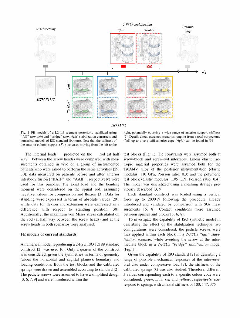
Given our interest in investigating the effect of the stabilization technique in the L2–L4 segment, only a physiological anterior column was considered here, while the specific effect of the anterior support stiffness (i.e., corpectomy, physiological anterior support, very stiff anterior cage) is specifically addressed in a previous study [3]. This choice is justified by the need to compare the instrumented L2–L4 spine segments with the correspond-ing construct implemented in ISO standard, which explic-itly implements a physiological anterior support [2, 7]. Therefore, two scenarios representing a posterior instru-mentation through pedicle screws and rods were considered (Fig. 1):
2-FSUs ‘‘full’’ stabilization The L2–L4 spine segment was instrumented with pedicle screws inserted at L2, L3 and L4 levels and a connecting rod;
2-FSUs ‘‘bridge’’ stabilization The L2–L4 spine seg-ment was instrumented with pedicle screws inserted at L2 and L4 levels and rod.
Both these configurations are widely used in clinical practice for the treatment of traumatic (i.e., fractures), degenerative and iatrogenic instabilities [17–27].
Details about the material properties and meshing used for each component of the L2–L4 spine segment (vertebral bod-ies, intervertebral discs and ligaments) can be found in pre-vious studies [28]. Linear elastic isotropic material properties were assumed for the Ti6Al4V alloy of screw and rods (elastic modulus 110 GPa, Poisson ratio: 0.3). The same meshing approach was adopted for each component: between 156,660 and 162,147 elements were used for each screw, while the rod resulted in 64,584 linear hexahedral elements [3, 9].
The models were preliminary validated by comparison of the internal loads measured in vitro using instrumented spinal fixators under pure compression [29] and pure bending moments in flexion and extension [30], as already described in [3].
To apply proper boundary conditions useful to mimic simple daily life activities for the instrumented L2–L4 model [31–33], three loading conditions were considered: standing (Follower Load = 500 N), upper body flexion (FL = 1175 N ? MFlex = -7.5 Nm) and extension (FL = 500 N ? MExt = 7.5 Nm). The FL load was sim-ulated using connector elements following spine curvature [3]. The lower endplate and the inferior facets of L4 were constrained during simulations.
test blocks (Fig. 1). Tie constraints were assumed both at screw-block and screw-rod interfaces. Linear elastic iso-tropic material properties were assumed both for the Ti6Al4V alloy of the posterior instrumentation (elastic modulus: 110 GPa, Poisson ratio: 0.3) and the polymeric test block (elastic modulus: 1.05 GPa, Poisson ratio: 0.4). The model was discretized using a meshing strategy pre-viously described [3, 9].
Each standard construct was loaded using a vertical force up to 2000 N following the procedure already introduced and validated by comparison with SGs mea-
surements [6, 8]. Contact conditions were assumed between springs and blocks [3, 6, 8].
To investigate the capability of ISO synthetic model in describing the effect of the stabilization technique two configurations were considered: the pedicle screws were thus applied within each block in a 2-FSUs ‘‘full’’ stabi-
lization scenario, while avoiding the screw at the inter-mediate block in a 2-FSUs ‘‘bridge’’ stabilization model (Fig. 1).
Given the capability of ISO standard [2] in describing a range of possible mechanical responses of the interverte-bral disc under compressive load [7], the stiffness of the calibrated springs (k) was also studied. Therefore, different k values corresponding each to a specific colour code were considered: green, blue, red and yellow, respectively, cor-respond to springs with an axial stiffness of 100, 147, 375
Fig. 1 FE models of a L2–L4 segment posteriorly stabilized using
‘‘full’’ (top, left) and ‘‘bridge’’ (top, right) stabilization constructs and
numerical models of ISO standard (bottom). Note that the stiffness of
the anterior column support (KA) increases moving from the left to the
right, potentially covering a wide range of anterior support stiffness [7]. Details about extremes scenarios ranging from a total corpectomy (left) up to a very stiff anterior cage (right) can be found in [3]
The internal loads predicted on the rod (at half way between the screw heads) were compared with mea-
surements obtained in vivo on a group of instrumented patients who were asked to perform the same activities [29, 30]: data measured on patients before and after anterior interbody fusion (‘‘BAIF’’ and ‘‘AAIF’’, respectively) were used for this purpose. The axial load and the bending moment were considered on the spinal rod, assuming negative values for compression and flexion [3]. Data for standing were expressed in terms of absolute values [29], while data for flexion and extension were expressed as a difference with respect to standing position [30]. Additionally, the maximum von Mises stress calculated on the rod (at half way between the screw heads) and at the screw heads in both scenarios were analysed.
FE models of current standards
A numerical model reproducing a 2-FSU ISO 12189 standard construct [2] was used [6]. Only a quarter of the construct was considered, given the symmetries in terms of geometry (about the horizontal and sagittal planes), boundary and loading conditions. Both the test blocks and the calibrated springs were drawn and assembled according to standard [2]. The pedicle screws were assumed to have a simplified design [3, 6, 7, 9] and were introduced within the

and 459 N/mm [35]. Details about the vertebrectomy sce-nario (no springs) [1] have been already reported [3].
To investigate whether ISO standard construct is able to differentiate the effect of the stabilization technique (full vs. bridge stabilization) in combination with such a wide range of anterior support stiffness, the internal loads (i.e., axial load and bending moment) on the spinal rods were analysed as a function of the vertical load for both con-figurations. The maximum von Mises stress values on screws and rod were also considered. Then, to study if the loading conditions described by ISO model may be rep-resentative of the effective clinical usage, the internal loads were compared with those arising in the more realistic L2–L4 stabilized spine models.
Simulations were run in ABAQUS/Standard 6.10 (Dassault Systemes Ri. Simulia, Waltham, MA, USA).
Results
Details about the full stabilization configuration (with screws at every level) both for the L2–L4 spine segment, as well as the ISO 12189 model, and the effect of the anterior support stiffness on the loads arising on the spinal implant have already been reported in previous studies [3, 6]. Therefore, only the effect of using a bridge stabilization on the loads of the spinal rod and the pedicle screws at dif-ferent levels is here reported.
FE models of instrumented L2–L4 segments
The internal loads predicted on the spinal rod for both instrumentation scenarios fall within the experimental measurements obtained in vivo on BAIF and AAIF patients from Rohlmann, Wilke and colleagues [29, 30, 34]
(Fig. 2a). Further details on the validation of these models can be found in [3].
As concerning the spinal rod, using a bridge instru-mentation involves lower average stress values than using a fully constrained stabilization construct, with a percentage difference of -10.2 % in standing, -12.6 % in flexion and -5.9 % in extension (Fig. 3a). The maximum stress on the spinal rod is reached upon upper body flexion with a maximum value of 169 MPa in the fully constrained con-dition, while in the bridge configuration it is lower (157 MPa).
As concern the stresses on the cranial (L2) and caudal (L4) screws (Fig. 3b), a bridge configuration involves higher average values than in a full construct both in standing (?9.1 %) and in flexion (?4.9 %), not in exten-sion (-15.4 %). The maximum value reached in standing is 132 MPa in bridge configuration (122 MPa using a full
stabilization), while in flexion it increases to 366 MPa (349 MPa).
The stress at the intermediate screw (L3) is about 60 %lower than the one experimented at the caudal/cranial levels in every loading condition (maximum value of 122 MPa in flexion).
The stress values achieved at the caudal (L4) screws are higher than on the cranial one (L2) both in standing (19.1 %) and in flexion (31.7 %) using the full construct; these percentages are slightly lower for a bridge stabiliza-tion (standing: 15.8 %, flexion: 11.9 %).
FE models of current standards
Regarding the spinal rod, when the recommended red springs are used, a bridge instrumentation involves lower bending moment than using a full stabilization construct (Fig. 2b) both upon release and even at peak load (-2.5 vs. 3.2 Nm), but the tensional loads increases (102 vs. 86 N). This results in lower average stress values than using a fully constrained stabilization, with a percentage difference of -8.3 % upon release and -22.4 % at peak load (Fig. 4a). The maximum stress on the spinal rod is reached at 2000 N with a maximum value of 201 MPa in the fully constrained condition, while in the bridge configuration it is only 156 MPa.
Given the symmetry of the model about the horizontal plane the upper/lower screws, as well as the superior/in-ferior parts of the spinal rod, undergo exactly the same loading mode (i.e., stress values). As concern the stresses on the superior/inferior screws (Fig. 4b), a bridge config-uration involves higher average values than in the full construct both upon release (?13.4 %) and particularly at peak load where it increases of a 62.5 %. The maximum values reached upon release is 263 MPa in bridge config-uration (232 MPa using a full stabilization), while at 2 kN it increases to 538 MPa (331 MPa using a full stabilization).
As concern the effect of a variation of the anterior support stiffness coupled to bridge stabilization, slightly higher percentage stress increase are reached at 2000 N considering a stiffer support (yellow spring, rod -28.3 %, screw ?63.2 %), while they reduce for the softest one (green spring, rod: -10.3 %, screw: ?26.8 %).
The stress at the intermediate screw (central test block) is more than 92 % lower than the one experimented at the superior/inferior level at peak load regardless the used set of springs (maximum value of 52 MPa at peak load). Changing the anterior support stiffness only produces a slight variation of such value (-97 % with the softest anterior support, i.e., green springs).

Discussion
The loads acting on a posterior spinal implant both during clinical use and during preclinical mechanical evaluation mainly depend on: the features of the experimental set-up [6, 9], the anterior support stiffness [3, 6], the applied force[3] and the stabilization technique.
‘‘full’’ 2-FSUs and a ‘‘bridge’’ instrumentation. A bridge instrumentation is preferred for the treatment of unsta-ble thoracolumbar burst and osteoporotic compression fractures: [17–21], several authors debated on the best indication, depending on the degree of anterior column instability [22, 23]: Carl recommends to use it from mid-
thoracic to lordotic fractures, but not at the thoracolumbar junction (i.e., longer lever arm of compressive forces and bending moment in flexion) [24]; Altay found that it can be safe without any anterior support at any level in Magerl type A31 and A32 fractures and it should be preferred from T12 to L2 levels for A33 fractures [22, 25]; Farrokhi rec-ommends it both for types A and B fractures (compressive and distractive, respectively) [17]. A full construct, with pedicle screws at the intermediate level, is sometimes used to treat unstable fractures [17, 26, 27], while it is widely used in degenerative and iatrogenic instability cases [19, 20, 26]. Tian and colleagues demonstrated that it can be applied to Magerl type A and B1 fractures, while Far-rokhi recommended it for types C (multidirectional and rotational) [17]. The findings here reported demonstrate how the stress experimented by pedicle screws in an incomplete bridge
Fig. 2 Axial load (top) and
bending moment in flexion–
extension (bottom) predicted on
the spinal rod for the L2–L4
instrumented segments during
standing, flexion and extension
(a), as well as in different
standard testing conditions as a
function of the applied force
(b). A further comparison with
in vivo measurements is
provided [3]. It should be noted
that the stiffness of the anterior
support (KA) progressively
increases moving from the left
to the right
(green\ blue\ red\ yellow
springs) in graph (b)
Recent studies highlighted that the geometrical set-up implemented in ISO standard match the anatomical and mechanical features of an average physiological subject [6, 9]. La Barbera and colleagues demonstrated that ISO modular anterior support covers the lower limit of the compressive response both of healthy, degenerated and treated IVDs and FSUs [6]. Moreover, they found a clear correlation between the loading condition prescribed by ISO standard, both in terms of the test set-up (i.e., set of calibrated springs) and the applied load (2 kN), and the posterior instrumentation of a 2-FSUs lumbar segment undergoing upper body flexion [3].
The present comparative numerical study is aimed to better understand whether a posterior spine stabilization implant tested under a compressive force according to ISO standard [2] can effectively predict the loading mode of a

Fig. 3 Maximum Von Mises stress values (rVM) predicted on the
spinal rod (a) and at the screw neck (b) on the L2–L4 instrumented
segment during standing, flexion and extension of the upper body.
Chess pattern indicates a ‘‘bridge’’ configuration. The stress values
are evaluated at half way between the screws head both for the
superior and inferior parts of the spinal rod (left), as well as for the
screws inserted at L2, L3 and L4 (right)
Fig. 4 Maximum Von Mises stress values (rVM) predicted on ISO model [2] on the spinal rod (a) and at the screw neck (b). Chess pattern indicate a ‘‘bridge’’ configuration. The stress values are evaluated on the spinal rod at half way between the screws head (left),
as well as for the screws inserted within the superior and central test
blocks (right). It should be noted that the stiffness of the anterior
support (KA) progressively increases moving downward
(green\ blue\ red\ yellow springs)
to the instrumented spinal levels (Pihlajamaki and Jutte: T12-S1, Farrokhi: T12-L2), as well as to the confounding effects of the indication for surgery and surgical techniques.
In this perspective the synthetic construct implemented in ISO anterior support model eliminates these confound-ing effects allowing to evaluate and compare the mechanical performance of a variety of spinal implants under repeatable and controlled conditions. Our study demonstrates the capability of ISO constructs in predicting the effects of using a full and a bridge instrumentation also justifying the use of both conditions during experimental reliability tests.
From a technical point of view, since experimental tests are made to evaluate and compare the mechanical performance of any new implant design, it is dramatically important to identify well-defined testing conditions which may serve also as a reliable basis of comparison between a variety of devices. While acknowledging the relative simplicity of the corpectomy model proposed by the American Society of Testing and Materials (ASTM), it is important to notice that such a loading condition is way too severe to represent any known clinical condition, but it guarantees a reasonably high safety coefficient, i.e., ratio of the maximum stress applied to the implant during testing and the one estimated during clinical use, even at very low loads [3]. The present study confirms, integrates and extends the findings already reported in a previous study, which questioned the value of ASTM vertebrec-tomy model and supported the use of ISO physiological construct being directly comparable to known clinically relevant condition [3]. La Barbera and colleagues [3] also proposed to compare the mechanical performance of a specific implant under the same bending moment in flexion: the graphs here provided (Fig. 2) can be used to determine the load to apply on each construct no matter of the assumed anterior support stiffness (ASTM vs. ISO with a specific set of springs) or the stabilization tech-nique (bridge vs. full instrumentation). Given a specific everyday life activity assumed as a reference, such as flexion or standing, it is possible to adjust the applied force to achieve a testing condition which is easy to compare across different experimental constructs (Figs. 5, 6). Considering the predominant range of movement of the spine during the everyday life [37] and the high load components on the anterior spine [38], it would be more reasonable to refer to upper body flexion as the activity more representative of the worst case loadings occurring in vivo [3, 6]. In this perspective, the implant assembled in a bridge construct and tested according to ISO proce-dure reaches stress values which are closer to the final clinical use, as found in the L2–L4 stabilization technique.
instrumentation may be higher than in a fully instrumented construct, both for the L2–L4 instrumented model and ISO construct (Figs. 3b, 4b). Such an aspect was explicitly investigated only by few clinical studies. In particular, Pihlajamaki and colleagues [20] reported a higher screw breakage rate for a multi-level bridge instrumentation (26.7 % or 16/71) than with a multi-level full instrumen-tation (0 % or 0/4) where the intermediate vertebra was also fixed [20]. The same trend was observed by Jutte and colleagues [19], who found screw breakage rate of 12.4 %(13/105). However, Farrokhi and colleagues [17] reported much lower screw failure rates for both stabilization techniques (bridge stabilization: 2.4 % or 1/42, full instrumentation: 2.6 % or 1/38), while Tian did not notice any breakage [27]. Other studies, focused only on short-segment bridge stabilization, reported variable failure rates from 0 % (0/63) [25] up to 14.3 % (4/28) [21].
As concern the broken screw location, Pihlajamaki, Jutte and colleagues observed that the great majority of broken screws (90.5 % or 19/21, 77.8 % or 14/18, respectively) are in the caudal portion of the posterior construct, par-ticularly when implanted in the lower lumbar levels and the sacrum [19, 20, 26]. The same trend was observed by Chen and colleagues [18] who reported 75 % (12/16) screw breakage events at the caudal level, but only half broke at the sacrum [18]. We hypothesize that the increasing overall load acting on the lower lumbar levels, combined to the marked curvature of this region, may explain these phe-nomena. Unfortunately, our L2–L4 instrumented model, being loaded with a constant FL at all levels and being relatively straight, does not describe these features; how-ever, we predicted a trend towards higher stress on the caudal screws than on the cranial ones particularly in standing and in upper body flexion for both stabilization techniques (Figs. 3, 4). A biomechanical in vitro study based on SG-technique glued directly on the neck of pedicle screw, confirmed that the stress on the caudal screw of a L2–L4 segment is significantly higher than at the intermediate one when axial compression is applied [36]: this confirms the result obtained in the full stabilization construct during standing.
Our results may support the idea that rod fracture is less common, since we observed that the maximum stress values reached on the spinal rod are about half the values obtained on the pedicle screws (Figs. 3, 4). This idea is confirmed by Pihlajamaki, Jutte and colleagues, who reported a lower rod failure rate (0 % or 0/102, 1 % or 1/105, respectively) than for the screws [19, 20]. However, this is in contradiction with Farrokhi and colleagues [17], who reported a much higher failure rates for the spinal rod particularly when a bridge instrumentation is preferred (16.7 % or 7/42) over a full instrumentation (2.6 % or 1/38). Discrepancies between these results may be related

The results here provided also allow to calculate the safety coefficient on each component of the spinal implant while tested according to different ISO scenarios (Fig. 6). Using a softer/stiffer (green/yellow springs) anterior sup-port would increase/decrease the margin of safety on every component, confirming the findings already achieved in a previous study [3]. Furthermore, using a bridge stabiliza-tion construct allows keeping a slightly higher average
safety coefficient than in a full construct, while stressing
more the pedicle screw.
While recognizing the need of experimental reliability
tests to support the clearing process of spinal implants, the
numerical approach herein adopted offers advantages in
terms of time and costs. In particular, it provides more
details on the stress/strain distribution in every component,
being more reliable over a purely experimental approach
Fig. 5 Safety coefficients of ISO experimental constructs at 2000 N
calculated with respect to the corresponding L2–L4 stabilization
model undergoing flexion (a) and standing (b), as a function of the
anterior support stiffness (i.e., spring stiffness) and the stabilization
technique. Notice that spring stiffness increases from left to right
(green\ blue\ red\ yellow springs), so the safety coefficient
progressively decreases. The anterior support stiffness (red springs) and load values (2000 N) recommended by ISO standard guarantee a safety coefficient close to 1 when compared to upper body flexion, suggesting that such a testing condition reproduces very well this scenario. Data from La Barbera and colleagues [3] are reported here for the sake of completeness (§)
Fig. 6 Force values to apply on
standard constructs, as a
function of the anterior support
stiffness (i.e., spring stiffness)
and the stabilization technique,
to obtain the same bending
moment on the rod, as predicted
on the 2-FSUs stabilization
model during standing (a) andflexion (b). Notice that spring
stiffness increases from left to
right
(green\ blue\ red\ yellow
springs). Data from La Barbera
and colleagues [3] are reported
here for the sake of
completeness (§)

based on strain-gauge (SG) technique, which may be affected by inaccuracies and lack in repeatability [3, 8].
The isotropic elastic material properties and the tie-con-straints at implant-bone interfaces and at screw-rod connec-tions are considered acceptable assumptions for a comparative study. The simplified design adopted for the implant is justi-fied by the need to keep the analysis general, but describing the overall features of widespread pedicle screw/rod-based sta-bilization implants [9]. Details on the sensitivity analysis on the geometrical parameters can be found in a previous paper [9], while further efforts to highlight the effect of the assumed material properties are needed.
Despite the assumptions here made are reasonable for an in vitro assessment, other limitations are to be acknowledged with respect to in vivo condition. For instance, specific variations in implant design, changes in implant positioning, changes in spine segments anatomy/
morphology should be considered. The consideration of muscle forces contribution and body weights may offer more accurate loading/boundary conditions over our simplified FL-based protocol. The investigation of dynamic loading condition, considering velocity/acceleration of the body, may elucidate interesting failure modes met in clinical practice which cannot be described using static simulations.
Conclusions
The anterior support stiffness (red springs) and force value (2000 N) described in ISO standard allow for describing upper body flexion. Using a bridge stabilization construct allows to keep a higher average safety coefficient than in a full construct, while overstressing the pedicle screw. Choosing a softer/stiffer springs would guarantee higher/lower safety coefficient on every component.
The study justifies the use of both conditions during in vitro reliability tests to achieve meaningful results easy to compare to clinically relevant loading modes and known in vivo failure modes.
Acknowledgments The authors declare that the study was not sup-ported by any funding.
Compliance with ethical standards
Conflict of interest The authors declare that they have no conflict of interest.
References1. ASTM Standard (2014) F1717: Standard test methods for spinal
implant constructs in a vertebrectomy model. doi:10.1520/F1717-15
2. ISO Standard (2008) 12189: Implants for surgery—mechanical testing of implantable spinal devices—fatigue test method for spinal implant assemblies using an anterior support
3. La Barbera L, Galbusera F, Wilke H-J, Villa T (2016) Preclinical evaluation of posterior spine stabilization devices: can the current standards represent basic everyday life activities? Eur Spine J. doi:10.1007/s00586-016-4622-1
4. Carson W, Asher M, Boachie-Adjei O, Akbarnia B, Dzioba R, Lebwohl N (2003) History of isola-vsp fatigue testing results with correlation to clinical implant failures. In: Melkerson M, Griffith S, Kirkpatrick J (eds) Spinal implants: are we evaluating them appropriately? STP 1431:3–16. ASTM International
5. Cunningham BW, Sefter JC, Shono Y, McAfee PC (1993) Static and cyclical biomechanical analysis of pedicle screw spinal constructs. Spine 18(12):1677–1688
6. La Barbera L, Costa F, Villa T (2016) ISO 12189 standard for the preclinical evaluation of posterior spinal stabilization devices—II: a parametric comparative study. Proc Inst Mech Eng H 230(2):134–144. doi:10.1177/0954411915621588
7. La Barbera L, Villa T (2016) ISO 12189 standard for the pre-clinical evaluation of posterior spinal stabilization devices—I: assembly procedure and validation. Proc Inst Mech Eng H 230(2):122–133. doi:10.1177/0954411915621587
8. La Barbera L, Ottardi C, Villa T (2015) Comparative analysis of international standards for the fatigue testing of posterior spinal fixation systems: the importance of preload in ISO 12189. Spine J 15(10):2290–2296. doi:10.1016/j.spinee.2015.07.461
9. La Barbera L, Galbusera F, Villa T, Wilke H-J (2014) ASTM F1717 standard for the preclinical evaluation of posterior spinal fixators: can we improve it? Proc Inst Mech Eng H 228(10):1014–1026. doi:10.1177/0954411914554244
10. Villa T, La Barbera L, Galbusera F (2014) Comparative analysis of international standards for the fatigue testing of posterior spinal fixation systems. Spine J 14(4):695–704. doi:10.1016/j. spinee.2013.08.032
11. Chamoli U, Diwan AD (2014) Tsafnat N Pedicle screw-based posterior dynamic stabilizers for degenerative spine: in vitro biomechanical testing and clinical outcomes. J Biomed Mater Res A (US) 102(9):p3324–p3340
12. Smith JS, Shaffrey CI, Ames CP, Demakakos J, Fu KM, Keshavarzi S, Li CM, Deviren V, Schwab FJ, Lafage V, Bess S (2012) Assessment of symptomatic rod fracture after posterior instrumented fusion for adult spinal deformity. Neurosurgery 71(4):862–867
13. Hyun SJ, Rhim SC (2010) Clinical outcomes and complications after pedicle subtraction osteotomy for fixed sagittal imbalance patients: a long-term follow-up data. J Korean Neurosurg Soc 47(2):95–101. doi:10.3340/jkns.2010.47.2.95
14. Sapkas G, Kateros K, Papadakis SA, Brilakis E, Macheras G, Katonis P (2010) Treatment of unstable thoracolumbar burst fractures by indirect reduction and posterior stabilization: short-segment versus long-segment stabilization. Open Orthop J 15(4):7–13. doi:10.2174/1874325001004010007
15. Hwang JH, Modi HN, Yang JH, Kim SJ, Lee SH (2009) Short segment pedicle screw fixation for unstable T11-L2 fractures: with or without fusion? A three-year follow-up study. Acta Orthop Belg 75(6):822–827
16. Korovessis P, Papazisis Z, Koureas G, Lambiris E (2004) Rigid, semirigid versus dynamic instrumentation for degenerative lum-
bar spinal stenosis: a correlative radiological and clinical analysis of short-term results. Spine (Phila Pa 1976) 29(7):735–742
17. Farrokhi MR, Razmkon A, Maghami Z, Nikoo Z (2010) Inclusion of the fracture level in short segment fixation of thoracolumbar fractures. Eur Spine J 2010(19):1651–1656

18. Chen CS, Chen WJ, Cheng CK, Jao SH, Chueh SC, Wang CC (2005) Failure analysis of broken pedicle screws on spinal instrumentation. Med EngPhys 27(6):487–496
19. Jutte PC, Castelein RM (2002) Complications of pedicle screws in lumbar and lumbosacral fusions in 105 consecutive primary operations. Eur Spine J 2002(11):594–598
20. Pihlajamaki H, Myllynen P, Bostman O (1997) Complications of transpedicular lumbosacral fixation for non-traumatic disorders. J Bone Joint Surg Br 79(2):183–189
21. Sanderson PL, Fraser RD, Hall DJ et al (1999) Short segment fixation of thoracolumbar burst fractures without fusion. Eur Spine J 8(6):495–500
22. McCormack T, Karaikovic E, Gaines RW (1994) The load sharing classification of spine fractures. Spine 19(15):1741–1744
23. Magerl F, Aebi M, Gertzbein SD, Harms J, Nazarian S (1994) A comprehensive classification of thoracic and lumbar injuries. Eur Spine J 3(4):184–201
24. Carl AL, Tromanhauser SG, Roger DJ (1992) Pedicle screw instrumentation for thoracolumbar burst fractures and fracture-dislocations. A calf spine model. Spine 17:317–324
25. Altay M, Ozkurt B, Aktekin CN, Ozturk AM, Dogan O, Tabak AY (2007) Treatment of unstable thoracolumbar junction burst fractures with short- or long-segment posterior fixation in magerl type a fractures. Eur Spine J 16(8):1145–1155. doi:10.1007/s00586-007-0310-5
26. Mohi EMM, Ali AM (2014) Lumbar transpedicular implant failure: a clinical and surgical challenge and its radiological assessment. Asian Spine J 8(3):281–297. doi:10.4184/asj.2014.8. 3.281
27. Tian JW, Wang L, Xia T, Liu CY, Zhao QH, Dong SH (2011) Posterior short-segmental fixation combined with intermediate screws vs. conventional intersegmental fixation for monoseg-
mental thoracolumbar fractures. Orthopedics 34(8):e389–e396. doi:10.3928/01477447-20110627-08
28. Galbusera F, Bellini C, Anasetti F, Ciavarro C, Lovi A, Brayda-Bruno M (2011) Rigid and flexible spinal stabilization devices: a biomechanical comparison. Med Eng Phys 33(4):490–496. doi:10.1016/j.medengphy.2010.11.018
29. Rohlmann A, Bergmann G, Graichen F, Weber U (1997) Com-
parison of loads on internal spinal fixation devices measured in vitro and in vivo. Med Eng Phys 19(6):539–546
30. Wilke HJ, Rohlmann A, Neller S, Schultheiss M, Bergmann G, Graichen F, Claes L (2001) Is it possible to simulate physiologic loading conditions by applying pure moments? a comparison of in vivo and in vitro load components in an internal fixator. Spine 26(6):636–642
31. Rohlmann A, Zander T, Bergmann G, Boustani H (2012) Optimal stiffness of a pedicle-screw-based motion preservation implant for the lumbar spine. Europ Spine J 21:666–673. doi:10.1007/s00586-011-2047-4
32. Rohlmann A, Zander T, Rao M, Bergmann G (2009) Applying a follower load delivers realistic results for simulating standing. J Biomec 42(10):1520–1526. doi:10.1016/j.jbiomech.2009.03. 048
33. Rohlmann A, Zander T, Rao M, Bergmann G (2009) Realistic loading conditions for upper body bending. J Biomech 42:884–890. doi:10.1016/j.jbiomech.2009.01.017
34. Rohlmann A, Bergmann G, Graichen F (1999) Loads on internal spinal fixators measured in different body positions. Europ Spine J 8(5):354–359
35. ISO Standard (2010) 10243: Tools for pressing—compression springs with rectangular section—housing dimensions and colour coding
36. Wu ZX, Zhan C, Cui G, Liu D, Wan SY, Zhang Y, Zhao X, Lei W (2012) Stress distribution on the screws in posterior lumbar fusion of isthmic spondylolisthesis with 2- or 3-vertebra fixation techniques: a biomechanical cadaveric study. J Surg Res 176(1):95–101. doi:10.1016/j.jss.2011.05.004
37. Rohlmann A, Consmuller T, Dreischarf M, Bashkuev M, Disch A, Pries E, Duda GN, Schmidt H (2014) Measurement of the number of lumbar spinal movements in the sagittal plane in a24-h period. Eur Spine J (Germany) 23(11):2375–2384. doi:10. 1007/s00586-014-3588-0
38. Rohlmann A, Pohl D, Bender A, Graichen F, Dymke J, Schmidt H, Bergmann G (2014) Activities of everyday life with high spinal loads. PLoS One (United States) 9(5):pe98510. doi:10. 1371/journal.pone.0098510