precision variable capacitors - philips no. 8 precision variable capacitors 237 table i. summarized...
TRANSCRIPT

---------- -----------------------------------------------------------------------------
234 PHILIPS TECHNICAL REVIEW VOLUME 20
PRECISION VARIABLE CAPACITORS
by A. A. TURNBULL *). 621.319.43
Electronic equipment for military uses is designed for specifications which require componentsof very high quality, Components must frequently be not only of high accuracy and stabilitybut must also be compact and robust. The article below describes two precision variable capac-itors which, although compact, have a performance comparable with laboratory capacitors ofconsiderably larger size.
Two types of precision variable capacitors (fig. 1)have been designed at the Mullard ResearchLaboratories for high grade electronic equipment,meeting stringent specifications as regards theiraccuracy and stability 1). One of these capacitorsgives a linear frequency law for use in transmittermaster-oscillator circuits or in receiver local oscilla-tor circuits. The other is a sine-frequency-law
requirement IS that the capacitors should besufficiently small to allow their convenient installa-tion in equipment, particularly in compact militaryequipment. The linear-law capacitor, for example,was originally designed for a specific equipment, inwhich three of these capacitors were ganged inline. In the layout of this equipment only a limitedspace was available for the capacitors. Similar
95605
Fig. 1. The two precision capacitors with covers removed. Left, the linear-law capacitor.Right, the sine-law capacitor.
capacitor and was designed primarily for the con-version of radar range and bearing informationfrom polar to cartesian form 2).The term stability in connection with these
capacitors implies stability over long periods,stability with respect to temperature variationsand with respect to vibration. In addition closelimits are imposed on any deviation from the rele-vant frequency law, and the capacitors must alsopossess a high degree of re-settability. A further
*) Mullard Research Laboratories, Salfords, Surrey, England.') A brief description has been published in Brit. Comm. and
Electronics 4, 756-759, 1957.2) British Patent No. 764478.
considerations also limit the size of the sine-lawcapacitor.
Some of the features common to both the capaci-tors may be described, before passing on to thedetailed consideration of each type. As stabilitywas the primary consideration in design, structuralrigidity is essential. For this reason the capacitorsare mounted in a robust cylindrical case with anaperture to permit access to the vanes during assem-bly. A cover to fit over this aperture is provided forelectrical screening and dust protection. A sub-stantially mono-metallic construction is used whichavoids stresses being set up due to differentialexpansions. In certain versions of the linear capaci-
}958j59, No. 8 PRECISION VARIABLE <;APACITORS 235
tor one of the rotor vanes is replaced by a bi-metallic vane to increase stability in cases wherethe equipment is not temperature-regulated. Thiswill be discussed further below.
Mechanical play in the rotors of the two capaci-tors has been practically eliminated by the use ofhigh-precision angular contact ball-bearings (seebelow) in which the eccentricity is less than 0.0001inch. The rotor is mounted in such a way thatthere is a. certain axial and radial load on thebearings; in this way both axial and radial slack-ness are, taken up and no play is possible.
Instability of electrical origin, such as varyingsurface conductivity or varying dielectric losses inthe insulators, is minimized by the use of high-gradeceramic insulators. These support the stator vanes,the rotor vanes being mounted on the earthedrotor assembly.
The temperature coefficient of capacitance isdetermined largely by the linear temperature co-efficient of expansion of the metal used. For bothcapacitors brass is used for most of the metal parts:this results in a temperature coefficient of capa-citance of +18 ±5 parts per million per °C.The shape of the vanes differs; of course, in the
two capacitors. The shapes required for the linearlaw and for the sine la,~ were first calculatedtheoretically. Considerable experimental work wasnecessary, however, to obtain the correct vane shapesto ensure precise conformity to the ideal curves.
Furthermore, in order that these accurate fre-quency laws are maintained from one capacitor toanother in production, particular care is necessaryin the choice of materials for the vanes and in theapplication of precision techniques for assembly.Stator and rotor vanes are assembled in specialjigs, as will be described presently.
Design of the linear law capacitor
The linear-law capacitor is designed for use inoscillator circuits in which a frequency coverageof two to one is required for a capacitance changeof about 300 pF. This is obtained in the presentdesign with an angular rotation of 150°. Over thisrange the capacity conforms to the ideallinear lawwithin ±0.05% in frequency. Furthermore the rateof deviation from the ideal law is nowhere greaterthan 0.02% in frequency per 5° shaft rotation.
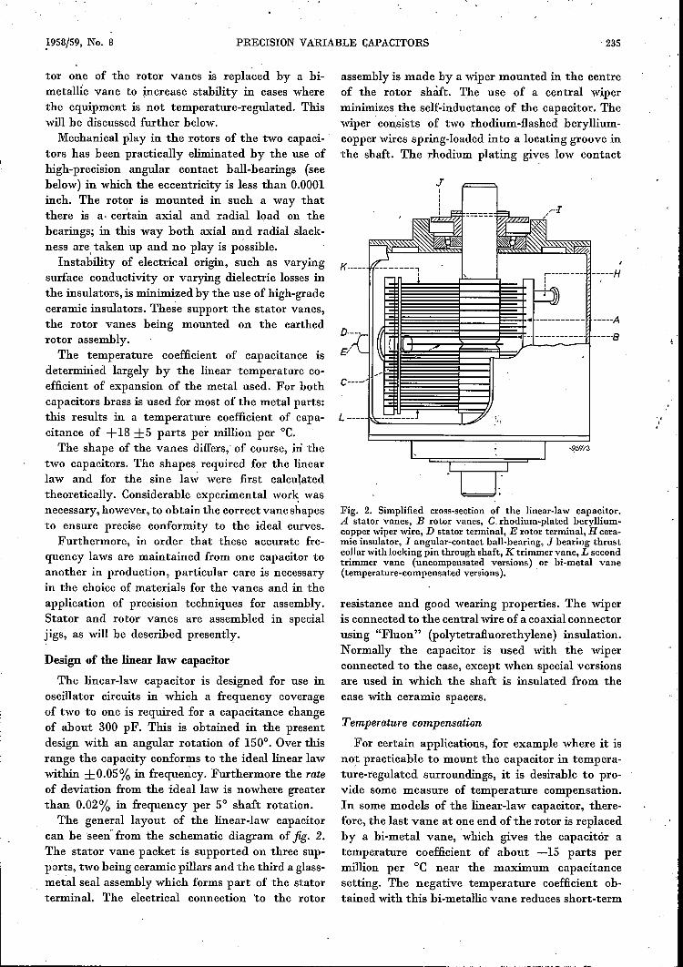
The general layout of the linear-law capacitorcan be 'seen' from the schematic diagram of fig. 2.The stator vane packet is supported on three sup-ports, two being ceramic pillars and the third a glass-m~tal seal assembly which forms part of the statorterminal. The electrical connection 'to the rotor
assembly is made by a wiper mounted in the centreof the rotor shaft, The use of a central wiperminimizes the self-inductance of the capacitor. Thewiper consists of two rhodium-flashed beryllium-copper wires spring-loaded into a locating groove inthe shaft. The rhodium plating gives low contact
III
Fig. 2. Simplified cross-section of the linear-law capacitor.A stator vanes, B rotor vanes, C,rhodium-plated beryllium-copper wiper wire, D stator terminal, E rotor terminal, H cera-mic insulator, I angular-contact ball-bearing, J bearing thrustcollarwith locking pin through shaft, K trimmer vane, L secondtrimmer vane (uncompensated versions) or hi-metal vane(temperature-compensated versions).
resistance and good wearing properties. The wiperis connected to the central wire of a coaxial connectorusing "Fluon" (polytetrafluorethylene) insulation.Normally the capacitor is used with the wiperconnected to the case, except when special versionsare used in which the shaft is insulated from thecase with ceramic spacers.
Temperature compensation
For certain applications, for example where it isnot practicable to mount the capacitor in tempera-ture-regulated surroundings, it is desirable to pro-vide some measure of temperature compensation.In some models of the linear-law capacitor, there-fore, the last vane at one end of the rotor is replacedby a hi-metal vane, which gives the capacitor atemperature coefficient of about -15 parts permillion per °C near the maximum capacitancesetting. The negative temperature coefficient ob-tained with this bi-metallic vane reduces short-term

236 PHILlPS TECHNICAL REVIEW VOLUME 20
instability of oscillator circuits due to variationin temperature by approximately compensatingthe normally positive temperature coefficientsassociated with the coil in the circuit. (With careand using selected materials it is possible to con-struct coils having a positive temperature coefficientas low as +15 p.p.m.re.)The figure of -15 p.p.m.re for the temperature
coefficient of the capacitor refers to the maximumsetting of the capacitor. The temperature coefficientnear the minimum capacitance settings will not beeffective in compensating temperature variationsin the coil inductance since, here, the capacitanceof the variable capacitor in circuit is a much smallerproportion of the total circuit capacitance. Approx-imate temperature compensation of the oscillatorat the minimum capacitance setting can be effectedby placing in parallel with the variable capacitora fixed capacitor Cp whose temperature coefficientis so chosen that near the minimum setting of thevariable capacitance the overall circuit-capacitancetemperature coefficient is -15 p.p.m.re. The overallcircuit capacitance then comprises (fig. 3a) theminimum .capacitance of the variable capacitor Cv,the fixed parallel capacitance Cp, and the straycircuit capacitance Cs' On now rotating the variable-capacitor shaft to near its maximum setting whereits temperature coefficient of capacitance is nominal-
I
L~g 7~ :~ _1. ;~-T-
v P t----v-'I C.
60 p.p.m./OC
4lJr-,
OCv ......
t 20 <,<,
b K0 ........._-20~~~~~~~~~~~~ __ ~ __ ~~
0° 20° 4lJo 60° 80° 700" 120° 14lJo 1600 18()0-9
96066
Fig. 3. Temperature compensation of linear-law capacitor.a) Tuned circuit consisting of the variable capacitor Cv, afixed parallel capacitor Cp, the stray circuit-capacitance plusthat of a trimmer C. and a coil L.b) Variation of the temperature coefficient acv of the variablecapacitor with angular setting of the shaft.c) Variation of total circuit capacitance aCt with angularsetting of shaft.
ly -15 p.p.m.rC, the overall circuit temperaturecoefficient of capacitance deviates only slightlyfrom -15 p.p.m.rC.
In fig. 3a, Cv is the capacitance of the variable capacitor,C. is the stray circuit capacitance plus the capacitance ofa trimmer, and Cpis the fixed parallel capacitance, of such avalue that the total capacitance in parallel with Cv isCp+ Cs= 65 ± 1 pF. (This value is the parallel capacitancenecessary to correct the variable capacitor and thus givepreciseconformity with the linear frequency law. Adjustment to theprecise value between the limits ± 1 pF is effected by anempirical method.)From f = L..J/.C..J/·/2nit follows (T = temperature) that:
df =.!_ [-tL-'I. ~/. dL _J..L..J/.c-'/. dC] =dT 2:n: dT or dT
= '-t [f :~ + f :;].If now we let af denote the temperature coefficient of frequencyf, aCt the temperature coefficient of the total circuit capaci-tance Ct and at. the temperature coefficient of the coil induc-tance, then
Since au is approximately +15 p.p.m.rC, we require thataCt be approximately -15 p,p,m.re in order that af may beapproximately zero.' The manner in which the temperaturecoefficient acv of the variable capacitor itself varies with theangular setting of the rotor is shown in fig. 3b. If now thetemperature coefficient acp of the fixed parallel capacitanceis adjusted (see below) such that at, say, the angular setting20°, the temperature coefficient aCt of the total circuit capaci-tance is nominally -15 p.p.m.rC, then aCt will vary with theangular setting of the rotor as shown in fig. 3c.It can be seen that the maximum value of aCt is approxi-
mately -21 p. p.m.re. At this point therefore, for «s. equalto +15 p.p.m.re, af would be -t(+15 - 21)= 3 p.p.m.rC.This simplified outline of the method of temperature compensa-tion, which ignores such factors as possible variations of aL
with frequency, shows that it is possible with sufficient careto effect temperature compensation to within 3 p.p.m.re overthe whole frequency range.It should be added that figs. 3b and crefer to a single typical
capacitor employing a bi-metallic compensating vane. However(see Table I below), there is a spread of ±10 p.p.m.re in thetemperature coefficient as between actual manufacturedcapacitors, near the maximum capacitance setting. Taking thisfactor into account it may not always be possible to effect thetempérature compensation of an oscillator to within 3p.p.m.rCbut it>should always be possible to achieve compensation towithin 10 p.p.m.rC (in frequency).
When the required temperature coefficient of Cphas been calculated, one method whereby it may beadjusted to the required value is to make Cp com-prise two fixed capacitors in parallel. One of thesecapacitors would normally be a high-grade silvered-mica capacitor and the other a relativily small-valued capacitor of silvered-ceramic construction.Since silvered-ceramic capacitors with a fairly wide

1958/59, No. 8 PRECISION VARIABLE CAPACITORS 237
Table I. Summarized specification for linear-law precisionvariable capacitor.
Capacitance at 0°. . . . . . . . 20.0 ± 1 pFCapacitance variation for 2: 1frequency range (for angularswing 26°-176°) . . . . . . . 292.8 pF
Conformity to linear law (withoptimum parallel capacitance). ± 0.05 % infrequency
Self-inductance. . . . . . . . . 0.015!LHPower factor at maximum capaci-tance, measured at 1 Mcls < 0.00005
Insulation resistance (stator . torotor). . . . . . . . . . . . > 1000 MO
Breakdown voltage measured at50 els . > 500 V r.m.s.
Torque < 6 oz.in. [<450g.cm=0.044 N.m]
Temperature coefficient near maxi-mum capacitance:for uncompensated versionsfor compensated versions
Dimensions:overall lengthoverall width
+ 18 ± 5 p.p.m.rC-15 ± 10 p.p.m.j=C
4.4 in.3.0 in.
range of known positive or negative temperaturecoefficients are obtainable, it is usually possible byselecting a suitable capacitor of.this type to achievethe correct temperature coefficient of the overallcircuit capacitance at the minimum setting (20°)and hence temperature compensation of frequencyover the whole range.
Design of the sine-law capacitor
The frequency law of the sine-law capacitor issuch that when the capacitor is connected in asuitable oscillatory circuit the oscillator frequencyvaries sinusoidally about a mean value as the rotorshaft is rotated continuously. This variable fre-quency may be expressed as:
fe =L« + f1 cos o.where fe is the oscillator frequency for the setting gof the shaft andfm is a fixed frequency. To convertpolar coordinates in a radar system to cartesians,which was the use for which this capacitor wasoriginally designed, the capacitor shaft is arrangedto rotate in synchronism with the radar aerialdirection e while the capacitor forms part of thefrequency-determining circuit of a variable-fre-quency oscillator. By beating the sinusoidally fre-quency-modulated signal fe = fm + f1 cos e withthe signal from a fixed-frequency oscillator of fre-quency fm, the resultant difference frequency isf1 cos e.If now a suitable gate is opened at the time the
radar tra~smitted pulse sets out, and closed again
at the moment the radar echo is received, the num-ber of cycles performed by the oscillator (which canbe directly counted) will be proportional to boththe range R of the target and also to cos e (jig. 4).
Fig. 4. Conversion of radar data from polar coordinates tocartesians, using the sine-law capacitor to produce a signaloffrequency porportional to the cosine of the angular position ofthe radar aerial. The time interval between transmission of apulse and reception of its echo is proportional to the range R.Hence for all points at a given range (R, say) this time is thesame. Since, however, the frequency of the signal transmittedin any direction e is proportional to cos e, the number ofcycles counted in the above-mentioned time interval is in eachcase proportional to cos e, so that this number of cycles is ameasure of the x-coordinatè R cos e. A similar arrangementgenerates the y-coordinate R sin e.
A second variable capacitor ganged 90° out of phasewith the first and forming part of a second oscilla-tory circuit enables R sin e to be generated,
The design of the sine-law capacitor follows thesame general lines as the linear-law capacitor. Themain differences are in the vane packets and in thewiper, which now has to stand up to continuousrotation. This capacitor is somewhat larger thanthe linear-law capacitor. The general layout isshown in jig. 5.As with the linear capacitor, the shape of the
vanes was derived theoretically and then the preciseprofile determined with the aid of experimentaldata. In this way it is possible to construct capacitorswhose capacitance is accurate at all settings towithin ±0.02% of the maximum capacitance.To obtain the conformity to within these close
limits, two extra vanes termed the corrector vaneand the trimmer vane are added to the rotor andalso two small. stator vanes termed stator Hags arepresent (their location is. shown in fig. 5). Fig. 6shows the shape of the vanes. The corrector vane isused to give' a coarse correction to the overallcapacitance law to within ±0.96 pF for all angularsettings. The final correction is made by adjustingthe segments of the trimmer vane. This va~e has acircular profile with 36 radial slots (see also fig. 1;the corrector vane is behind the trimmer vane inthis photograph and is therefore not visible). Itwill be noted from fig. 6 that all rotor vanes includ-

238 PHILIPS TECHNICAL REVIEW VOLUME 20
---C---A
95977
Fig. 5. Simplified drawing showing construction of sine-lawcapacitor. A stator vanes, B rotor vanes, C silver-graphitewiper brush, D stator terminal, E rotor terminal, connectedto case, F stator flags, G silver slip ring, H ceramic insulators,I angular-contact ball-bearing, J bearing thrust collar withlocking pin through shaft, K trimmer vane, L corrector vane.
ing the corrector and trimming vanes and the statorvanes are symmetrical about a central line, so thatthe law of the capacitor obtained as the rotor shaftis rotated from 00 to 3600 is symmetrical about 1800
(defining 00 to correspond to minimum capacitance).
oA
L
8
F KFig. 6. Profiles of vanes in sine-law capacitor. A stator vane,B rotor vane, E the two stator flags,L corrector vane, showingrelative positions of stator flagson either side of vane, K trim-mer vane, showingrelative position of the smaller stator flag.
, The equipment for which this capacitor was de-signed provides temperature stabilization for theoscillator components. No bi-metallic temperature-compensating vane is therefore needed, althoughit is still necessary that the temperature coefficientof the capacitor should be small and held withinclose limits. In fact the temperature coefficient isheld to within +18 ±5 p.p.m.re at maximumcapacitance (see Table II).
--8Table ll. Summarized specification for sine-law precisionvariable capacitor.
Frequency law. . fe = fro +f1 cos e,wherefm = 500 000 cJsandf1 = 47 680 cJs
30.5 pFCapacitance at 0°Capacitance swing 0°-180° (and
180°-360°). . .Conformity to law . . . . . . .
398 pF± 0.02 % of maximum
capacitancePower factor at maximum capaci-tance, measured at 1 McJs
Torque .< 0.0003< 3 oz.in. [<225 g.cm =0.022 N.m]
Temperature coefficient of capaci-tance ....
Dimensions:overall lengthoverall width
+18±5 p.p.m.rC
5.0 in.3.25 in.
The sine capacitor has to be used under conditionsof continuous rotation for exceptionally long periodswithout any significant wiper-bearing wear takingplace. The design provides for a shaft rotation at arate of 10 r.p.m. for not less than 5 million revolu-tions. To achieve this long life and to give a con-sistently low contact resistance (approximately0.001 Q), the capacitor uses a wiper consisting ofsilver-graphite brushes bearing on a silver slip ring ,(see fig. 5).The stator vane packet is supported from the
cylindrical case and insulated from it by fourceramic pillars. A further ceramic pillar supportsthe two stator flags. The capacitor terminals arecoaxial, "Fluon" insulation being used for the statorconnector.
Manufactw-e and assembly
The method of assembling the vanes consistsbasically of applying precision techniques to afairly standard procedure. The principle involvedis that of assembling the rotor shaft together withthe rotor and stator vanes as one unit. The vanesare separated by spacer vanes and accurately jiggedin their correct relative positions while the rotorvanes are soldered to the shaft and the tie bars to

1958(59, No. 8 PRECISION VARIABLE CAPACITORS 239
95Mb
a
c
bFig. 7. a) Assembly jig with stator, rotor and spaeer vanes inposition. b) View of vane packet of linear capacitor afterremoval from jig. A stator vanes, B rotor vanes, C spaeer vanes(only four shown in position, for clarity). D stator-vane tiebars, E trimmer vane. The shape of the spaeer vanes is shownon the right.
the vanes. The jig used for this purpose is shown in.fig. 7a. The sketch of fig. 7b shows a view of theassembly after removal from the jig. This assembly(with the spaceI' vanes still in position) is nowmounted within the capacitor case. This is effectedby locating the inner halves of the bearing raceson the shaft and loading them on the outer raceswith a thrust of 40 pounds weight, which is appliedto collars that are also located on the shaft and sub-sequently locked to the shaft with taper pins. Atthis stage the complete vane packet (i.e. includingthe stator vanes) is free to rotate with the shaft.The stator vane packet is then fixed to the insulatedsupports which are mounted on the capacitor case,by soldering the tie bars to the supports. In thismanner, throughout the assembly of the capacitor,the accurate relative positioning of the rotor andstator vane packets is maintained. The final opera-tion of removing the spaceI' vanes permits the shaftto be rotated.
95978
The accuracy of the capacitors is determined toa very large extent by the tolerance on the thicknessof the spaceI' vanes. The brass strip from which thespaceI', rotor and stator vanes are blanked under-goes a process during its manufacture when thesurface is shaved to yield a very close tolerance onthickness such that there are no greater variationsthan about 0.0004 inch from the nominal value andno greater variations in thickness over the wholearea of anyone metre long strip than 0.0001 inch.In order that the average rotor-to-stator spacingshould be even more accurately controlled, one halfof the spaceI' vanes used for anyone capacitor aremade of strip with a thickness error no greaterthan 0.0002 inch in excess of the nominal value whilethe other half are made from strip with the sameerror in thickness less than the nominal value.
For the linear-law capacitor the method of assem-bly of the rotor and stat or vanes must be such thatthe resultant law of the capacitor, prior to adjust-ment by means of the trimmer vane, be withinapproximately 0.25% in frequency. Only then canthe final adjustment by means of the trimmer vanebe effected to the required tolerance of ±0.05% infrequency.
Both capacitors are mounted by clamping in aU-shaped cradle, a basic type of which is shown infig. Ba.
A special flexible coupling has been designed forthe purpose of ganging the capacitors to each otherand to the drive shaft. A collar is attached to eachshaft by means of grub screws, each collar beinglinked to a rigid outer rim by means of a flexiblecorrugated diaphragm (see fig. 8b). With the shaftsaligned and set at the correct relative angle, the
a b 96855
Fig. 8. a) Basic form of the mounting cradle for the precisioncapacitors. b) Flexible coupling used for ganging the shafts.The collars C of each half are locked with grub screwsto the two shafts such that, with the shafts at their desiredrelative orientation, the three pins P are approximatelyaligned with the three pins P.' After the grub screws have beentightened, the shafts are set precisely to the correct relativeorientation and solder is run over the junctions of the pins.D are corrugated metal diaphragms.

240 PHILIPS TECHNICAL REVIEW VOLUME 20
two rigid rims are then locked together by runningsolder between the two sets of three pins. Thisprocedure avoids the slight relative rotation betweenthe two shafts that usually occurs when the grubscrews of a coupling are tightened onto the shafts.
Performance and characteristics
The linear-law capacitor
Over a frequency range of 2: 1 (a capacitanceswing of approximately 300 pF), the linear capaci-tor conforms to the straight-line law to within±0.05% in frequency as is required. Fig. 9 is agraph for a typical capacitor showing how the errorsvary with the angular setting of the shaft. It canbe seen that nowhere do the errors exceed 0.05%in frequency between the angles 18° and 176°. Thefrequency coverage of 2 : 1 is obtained between theangles 26° and 176° (the same frequency coveragemayalso be obtained between other pairs of angles,
600cj
.!lft 2
s
- __i--_ _-
I-_ 1--_
00-_ -
0 \ I" ho /"V r-, I/""". /"'\"- - ,
"v -__- __ - __
_'--- ---000 °
-2
-400
-6 o ~ 40 60° 80° 100° 120° 140° 760° 78CJO96071 -9
Fig. 9. Typical curve for a linear-law capacitor showing devia-tions iJf from the straight-line frequency law against angularsetting e. From 26° to 176° the oscillator frequency passesfrom 800 kc/s to 400 kc/soThe two oblique dotted lines corres-pond to frequency errors of ± 0.05%.
such as 22° and 174° or 18° and 172°). As mentionedabove, this performance is obtained when the totalcapacitance in parallel with the variable capacitorsis 65 ± 1 pF.
The temperature coefficients of capacitance ofboth versions of this capacitor, i.e., temperature-compensated and non-temperature-compensated,have been given above (see also Table I).
The long-term stability of a numb~r of capacitorshas been measured in the laboratory over a periodof several years. Periodic measurements of theirfrequency calibration curves show that thesecapacitors have a stability of better than ±0.02%in capacitance. Some long-term-stability testsperformed by the National Physical Laboratoryare shown in fig. io« The relative humidity at thetimes of the measurement is shown in fig. lOb.The strong correlation between these quantities
96068 ..
Fig. ID. Uncompensated linear-law capacitor.a) Variation, over a period of ma!ly months, in the capacitanceswing between the settings 0° and 170°, expressed as a per-centage of the capacitance at 170°, measured at 1 kc/sob) Corresponding readings of relative humidity H taken atthe same times as the measurements of L1C/Cl70-
It should be pointed out that these variations in capacitance,which are themselves very small, give rise in practice to muchsmaller percentage frequency variations owing to the presenceof a parallel capacitance (fig. 3).
shows that to minimize capacitance variationsdesirable to use the capacitor under conditions oflow relative .humidity, This can be achieved fairlyeasily by raising the temperature of the immediatesurroundings slightly above the ambient tempera-ture, or by dessicating the capacitor enclosure.
Vibration tests carried out over the frequencyrange between 10 cis and 150 cis with correspondingaccelerations of 0.2g-6.8g produce only slightchanges in capacitance. In all cases the frequencylaw remains unaltered well within the specifiedlimits of ±0.05%.
The sine-law capacitor
The accuracy achieved in the sine-law capacitoris ±0.02% of the capacitance swing. Since thelatter is about 400 pF (0°-180°, and 180°-360°), theaccuracy of the capacitor is within about ±0.08 pFfor all angular settings. Fig. 11 is a graph showingthe departure from the ideal law for a typicalsine-law capacitor. Also shown in this graph arethe specification limits in terms of the frequency(equivalent to ±0.08 pF).Table II summarizes the properties of this capa-
citor.
Fig. 11. Deviation Llfin cis of a typical sine-law capacitor fromthe ideal sine frequency law, the frequency swing of theoscillator being from 452.32 kc/s to 547.68 kc/so The dottedlines above and below the curve represent the specificationlimits (equivalent to ±0.08 pF).

1958/59, No. 8 PRECISION VARIABLE CAPACITORS 241
9'\808
Fig. 12. Precision instrument used for setting angles of the sine-law capacitor. (Opticaldividing head by Messrs Precision Grinders Ltd., Mitcham, Surrey, England.)
Measurements have been made to assess thelong-term stability of several of these capacitors.These measurements are not easy, however, becauseof the difficulty in defining the angular position ofthe shaft of each capacitor. The shaft of this capaci-tor can rotate continuously, i.e. it has no end stop;
____Jt,
00 95976-9
Fig. 13. Indicating the setting of the sine-law capacitor to thetwo datum positions at 90° and 2700 where the oscillatorfrequency is equal to fm.
it is therefore much more difficult to set up thiscapacitor to any datum position. In the absence ofa mechanical datum, a method of setting-up byelectrical means has to be used. The capacitor ismounted on an instrument whose shaft, coupledto the rotor ofthe capacitor, can be set to any desiredangle with a high degree of precision (to approxi-mately 9 seconds of arc). A photograph of thisapparatus is shown in fig. 12. The shaft is locked tothe instrument and the positions (180° apart) atwhich the circuit gives the same frequency are found
experimentally. (Since the law of the capacitor It,
fe = fm + I, cos e, there are two positions of theshaft at 90° and 270°, differing by exactly 180°,which give rise to the same oscillator frequency fm,see fig. 13.) Using these two measured angularpositions as the datum angles, measurements showthat the instability of the capacitors is not greaterthan ±0.01 % of maximum capacitance over periodsof up to three months. Periodic measurements havealso been made on two capacitors, while actuallyinstalled in their equipment, over a period of someeighteen months. No evidence of instability greaterthan ±0.02% of maximum capacitance has beenfound over this period.
Summary. Two precision variable capacitors are described,one giving a straight-line frequency law and the other a sinefrequency law. In order to achieve high accuracy and stability,both capacitors have precision bearings and are mounted inrigid cylindrical cases. The vanes are manufactured from brasssheet machined to close tolerances. The linear-Jaw capacitorhas a capacitance variation corresponding to 2: 1 in frequency,for an angular swing of 26° to 176°. The deviation from thestraight-line law is never greater than ±0.05% in frequency.The temperature coefficient of capacitance is about +18 partsper million per oe. Special temperature-compensated versions,however, have a temperature coefficient which is equal to-15 p.p.m.j"C. The sine-law capacitor is designed so that itsshaft can rotate continuously for long periods. Special atten-tion is therefore paid to the wiper contacts which are of silver-graphite, bearing on a silver slip ring. The capacitance swing(from 0°-180° and 180°-360°) is 398 pF. Conformity to thesine law is within ±0.02% of maximum capacitance. Thetemperature coefficient is + 18 p.p.m.;oC. One important useof this capacitor is for the conversion of radar data from polarto cartesian form.

242 PHILIPS TECHl'iICAL REVIEW VOLUME 20
ABSTRACTS OF RECENT SCIENTIFIC PUBLICATIONS BY THE STAFF OFN.V. PHll.IPS' GLOEll.AMPENFABRIEKEN
Reprints of these papers not marked with an asterisk * can be obtained free of chargenpon application to the Philips Research Laboratory, Eindhoven, Netherlands.
2581: A. Claassen and L. Bastings: The extractionof ferric chloride with methyl isobutyl ketoneand amyl acetate (Z. anal. Chem. 160, 403-409, 1958, No. 6).
The extraction of iron as ferric chloride in 7 Mhydrochloric acid by a mixture of (1+1) or (2+1)methyl isobutyl ketone and amyl acetate is quantita-tive for macro as well 'as for micro amounts of iron.The distribution ratio is very high (1"-...4000). Withthese mixtures no emulsification difficuhies areencountered as they are with methyl isobutyl ketonealone. The behaviour of 44 elements in this extrac-tion has been investigated.
2582: H. O. Huisman, A. Smit and J. MeItzer:Investigations on organic insecticides, 1.Preparation and insecticidal properties ofsome substituted polyenamides (Rec. Trav.chim. Pays-Bas 77, 97-102, 1958, No. 2).
The preparation and insecticidal properties of anumber of substituted polyenamides are describedin connection with the occurrence of this type ofcompound in nature.
2583: H. O. Huisman, J. H. Uhlenbroek and J.MeItzer: Investigations on organic insectici-des, Il. Preparation and acaricidal propertiesof substituted diphenylsulphones, diphenyl-sulphides and diphenylsulphoxides (Rec.Trav. chim. Pays-Bas 77, 103-122, 1958,No.2).
The preparation and acaricidal properties of anumber of variously substituted diphenylsulphones,diphenylsulphides and diphenylsulphoxides are des-cribed. A few of them possess strong acaricidal prop-erties. The most outstanding proved to be 2,4,5,4'-tetrachlorodiphenylsulphone - "Tedion V18" -which combines high activity on all stages, exceptaduIt spider mites, with t~tal absence of phytocidalside-effects and toxicity for warm-blooded animals.
2584: T. Krait, H. D. Moed and J. van Dijk:Ionylamines, 1. Synthesis of' di- and tetra-hydro-a- and - ,B-ionylamines and their spas.-molytic action (Rec. Trav. chim. Pays-Bas77, 177-195, 1958, No. 3).
The synthesis and properties of amines and quat-ernary ammonium compounds with the C-skeleton
of ionone and CIs-ketone are described. The spas-molytic activities of the compounds were determined.The results are discussed and it is concluded thatthese series of amines show a high musculotropicspasmolytic activity. The relationship between thechemical structure and the spasmolytic activity inthese series of amines is fairly clear and regular.
2585: H. D. Moed, T. Krait and J. van Dijk:Ionylamines, 11. Synthesis of tetra- andhexa-hydro-e-ionylamines and their spas-molytic action (Rec. Trav. chim. Pays-Bas77, 196-208, 1958, No. 3).
The synthesis and properties of amines with theC-skeleton of 1p-ionone are described. The spas-molytic activities of the compounds have been de-termined. The results are discussed and the con-clusions are reached that the 1p-ionylamines forma series of compounds with high musculotropicspasmolytic activity and that in this series thereexists a fairly clear and regular relationship betweenchemical structure and spasmolytic activity.
2586: H. Koopman and J. Daams: Investigationson herbicides, 1. 2- (substituted amino) -4,6-dichloro-l,3,5-triazines (Rec. Trav. chim.Pays-Bas 77, 235-240, 1958, No. 3).
In view of their herbicidal properties a numberof 2-(substituted amino )-4,6-dichloro-l,3,5-triazineswere synthesized by a method described in theliterature. The influence of the side chain on theherbicidal properties was determined. For this reasonsome derivatives mentioned in the literature wereincluded to compare them with the new compoundsin the authors' biological tests.
2587: M. P. Rappoldt, P. Westerhof, K. H. Hane-wald and- J. A. Keverling Buisman: Inves-tigations on sterols, X. The conversion ofergosterol and pre-ergo calciferol by U.V.light of 254 mIL (Rec. Trav. chim. Pays-Bas77, 241-24.8, 1958, No. 3).
A study is presented of the conversion of ergo-sterol and pre-ergo calciferol by U.V. light of 254mIL. From the experiments certain conclusions aredrawn regarding the formation of tachysterol., fromergosterol and on the quantum-efficiency of the inter-conversion of pre-ergo calciferol and tachysterol2•

1958/59, No. 8 ABSTRACTS OF RECENT SCIENTIFIC _PUBLICATIONS 243
2588: H. D. Moed, J. van Dijk and H. Niewind:Synthesis of p-phenylethylamine derivatives,
. V. Bronchodilators II (Rec. Trav. chim. Pays-Bas 77, 273-282, 1958, No. 4).
The chemistry is described of three adrenaline-like compounds:
RHO-::::=~-CHOH-CH2-NH-CH-CH2::::+~/- I =
HO CH3(R= o-OH, m-OH and m,p-(OH)2)
The compounds were examined for their ability toprotect guinea pigs from bronchial spasm inducedhy-acethylcholine. Thepossible influence of thehy-droxylated benzene nucleus of the side chain onthe drug-receptor combination is discussed.
2589: M. P. Rappoldt, J. A. Keverling Buismanand E. Havinga. Studies on vitamin-D andrelated compounds, VIII. The photoisomer-isations of provitamin-D and its irradiationproducts (Rec. Trav. chim. Pays-Bas 77,327-330, 1958, No. 4).
Results of kinetic investigations and measure-ments of quantum yields are reported, which cannotbe explained by the most simple scheme imaginablefor the photochemical interconversions of provita-min-D and its isomers. At least two excited trans-itory species have to bé assumed. More experimentaldata will he needed before a decision can he madein favour of one or other of the hypothetical,more complicated, pathways.
2590: W. Haidinger: Ein Beitrag zur Kenntnisder brennflecklosen Bogenentladung (Z. Phy-sik 151, 106-113, 1958, No. 2). (Contributionto the study of arcs without cathode spot;in German.)
For high-pressure xenon discharges with shortarcs, it is shown that the transition from an arewith cathode spot to an are without cathode spotis dependent on 'the form and emission of the cath-ode. A special cathode is described for which thetransition current under otherwise equal conditiorisis reduced by about 40%. When this cathode isprovided with readily emitting substances, the tran-. sition current can he diminished more' than 85%:Contrary to earlier experience a re-ignition peak isobserved at small currents (low cathode tempera-ture) with this are.
2591: J. Hornstra: Dislocations In the diamondlattice (Phys. Chem. Solids 5, 129.014.1,1958,No. 1/2). '
In this paper· several possible structures of dis-
. locations in the diamond lattice· are discussed.Special attention is paid to the occurrence of bro-ken bonds in the core of the dislocations and injogs; for instance, edge-type dislocations can occurin configurations without broken bonds. Jogs canact as a source or sink of interstitials and vacancies;in the diamond lattice this is complicated by theexistence of two kinds of atom sites. The mostprobable types of partial dislocations and themechanism of their formation from simple dis-locations are discussed. In the last section some-thing is said about the occurrence of partial dis-locations at twin boundaries and about a lineimperfection with zero Burgers vector 'which mayoccur at the end of a twin lamella.
, I' . .J. H. Spaa: A beam-scanned rotating heavy-ice target for high loads (J. sci. Instr. 35,175-178, 1958, No. 5).
Of the several possible targets for the D(d,n)3He -reaction the heavy-ice target proves to be themost suitable' fo~ outputs of about 1010 neutronsper second.' Beam scanning in two perpendiculardirections combined with rotation of the targetis found to be necessary t? secure a sufficient lifeof the ice surface.
2592:
2593: F. A. Kröger and H. J. Vink: Relations be-tween the concentrations of imperfections insolids (Phys. Chem. S.9lids 5, 208-223, 1958,No.3). .
Imperfect crystals behave statistically like liquidsolutions, the crystal being the solvent and the im-perfections the solutes. Application of the law ofmass action to atomic and electronic reactions tak-ing place in the crystal and between the crystal andthe other phases leads to the notion that the con-centrations of the various imperfections are inter-dependent as a result ofreactions having partners incommon. The consequences of this interdependenceare demonstrated by means of a graphical method.Imperfections having opposite effective chargestend to increase each other's concentrations. Foreignatoms are incorporated in a manner dependentboth on the energy levels caused by them and onthe type of imperfection prevailing in the crystalin the absence of these foreign atoms. In monatomicsolids the mechanism of incorporation can be in-fluenced only through the remperature; in com-pounds it can also be influenced through the partialpressures of the components of the basis crystal.It is shown that the arguments given are validirrespective of the type of bonding.

244 PHILlPS TECHNICAL REVIEW VOLUME 20
2594: G. D.' Rieck: Growth and preferred orienta-tions of crystals in tungsten wires (Actametallurgica 6, 360-366, 1958, No. 5).
In reerystallized wires of doped tungsten, largecrystals have their [421] or [531] axis parallel tothe wire axis and small ones tend to keep the origi-nal deformation texture (110]. It can be shown that,assuming glide both along (111) and along (lOO)in the tungsten crystals during drawing, the majori-ty of the crystals attain a [110] texture. However,some crystals which have an orient~tion near [531]deform on one glide system only. Therefore, duringthe last stages of drawing, they will tend to turn'with respect' to neighbouring crystals 'having a[110] texture. The presence of a dope inhibits the
. . growth of .most of the crystals, but least so that ofthe [531] crystals, as these will have undergoneconsiderable grain boundary slip, resultingin crumbl-ing of the dope skins. Less dope results in more
- smaller crystals, fewer of which have [531] orienta-tion. The nature of the fragmentation which wàsalready found in the large crystals can be explainedon the assumption of tubes or strings of contamina-tions with blocks and leaks at random places.
2595: J. J. de Jong, J. M. G. Smeets and H. B.Haanstra: Some results of an electron-microscopical study of the metallographicstructure of two alloys for permanent mag-nets (Ticonal G and Ticonal X) (J. appl.Phys, 29, 297-298, 1958, No. 3).
The microstructures of "Ticonal" G and X in thecondition of optimum magnetic properties are studiedby the electron microscope using the dU:ect carbonreplica. It is argued that a very critical and exten-sive checking of results is essential in order to arriveat reliable conclusions. Work along these lines de-monstrates that a) the main structural patternsfor "Ticonal" G and X are the same, b) the detailsof the structure of "Ticonal" G and X differ strikinglywith respect to texture, width, length-to-widthratio, delineation and intergrowth, and c) theinfluence of the magnetic field during cooling onthe structure of "Ticonal" G on a plane II Hu can beshown directly. It cannot yet be decided whetherthe structure in the optimum condition is a truetwo-phase structure or a single-phase structurewith periodic fluctuations in composition. It ispossible that the dimensións revealed by etching donot represent those of the magnetic 'areas. (Photo-
graphs showing the microstructure of "Ticonal" Ghave appeared in this Review; see Vol. 19, 11-14.,1957/58.)
2596: A. L. Stuijts and H. P. J. Wijn: Preparatienand properties of crystal-oriented ferrox-plana samples (J. appl. Phys. 29, 4.68-469,1958, No. 3).
Samples of the hexagonal ferroxplana materials,with a preferential plane for the magnetization,show an increased resonance frequency compared tosamples of cubic ferrites with the same permeability.It has heen found possible to use the làrge stiffnessfor rotation of the magnetization out of the prefe-rential plane, in order to orientate the single crystalparticles of a ferroxplana powder in a magneticfield. In this way samples. with two different textureshave been obtained. In one case the basal planesof the crystals have one direction more or less incommon (fan texture); in the other case all basalplanes lie ~ore or less parallel to each other (foliatetexture). In both cases the permeability is' appre-ciably increased, while the resonanée frequency isonly slightly decreased. Permeabilities of 56 at90 Mc/s and 28 at 230 Mc/s, both for tan 0 = 0.1,have been found. This large increase in permeabilityis caused mainly by an elimination of the effect ofthe anisotropic permeability of the crystals. .
2597: i. Meltzer and F. C. Dietvorst: Action ofTedion on eggs and ovaries of spider mites(T. PI.ziekten 64, 104.-110, 1958, No. I).
Eggs of Tetranychus urticae Koch ofnought to fourdays of age do not differ in susceptibility to "Tedion" .The moment of kill after treatment with "Tedion"is not restricted to a special stage of develop-ment. However, most kill occurs between egg stageand nymphochrysalis. "Tedion" affects developingeggs in the ovary of Tetranychus urticae Kochafter the females have taken up "Tedion" orally. Thiseffect lasts for at least five days after transfer of thefemales to untreated plants. With CPBS and "Chlor-benside" no complete kill is obtained in this manner,even less than a day after transfer to untreatedplants. "Tedion" affects also' the developing eggs inthe ovary of Metatetranychus ulmi Koch. However,in this species the killing effect is lost within two tofour days after transfer of the females to untreatedplants. "Chlorbenside" acts slightly less in this man-ner, whereas CPBS is far less active.
"