precision tooling systems for mills - hardinge, inc. tooling systems for mills 2—precision tool...
TRANSCRIPT

www.hardinge.com
HARDINGEPrecision ToolingSystems for Mills

2—Precision Tool Holding Systems for Mills Hardinge Inc. | 800.843.8801 | www.shophardinge.com
Precision Tool Holding Systems for Mills
Hardinge. Solid since 1890.
At Hardinge, our mission is to pro-
vide the Best Value in workholding
products to meet demanding pro-
duction levels and produce the quality
of parts required in a competitive
industry. When it comes to the tool-
holder, value is all about precision
and reliability.
The quality of the toolholder is
directly reflected in the quality of the
part. Our standard of performance
is high to help you achieve the level
of accuracy required for automotive,
medical, aerospace and the electronics
industries, not to mention the zillions
of parts that involve the safety of our
day-to-day activities.
Our BT and CAT-V flange CNC tool
holding systems are precision ground
to assure a stable holder with the best
possible TIR, resulting in better surface
finishes, longer tool life and a more
accurate workpiece.
Take pride in precision machining.
Step up to Hardinge for precision tool
holders, toolholder collets and acces-
sories to meet your milling machine
requirements.
We’ve built in the Value for longer
lasting tool holders – you’ll save in
the long run.
Hardinge offers many tooling and workholding solutions for the mill. Collet
Blocks, Rotary Tables and Indexers are available to hold or position your parts.
Collets, Sure-Grip® expanding collets, step chucks, chucks, and fixtures can be
held in the collet block or a rotary table or indexer for a variety of OD and ID
gripping solutions.
Rotary Tables & Indexers; page 50, full-line brochure 2372. Collet Blocks; page 51, full-line brochure 2365.
Hardinge Inc. | 800.843.8801 | www.shophardinge.com Precision Tool Holding Systems for Mills—3
www.Shop HARDINGE.comTable of Contents
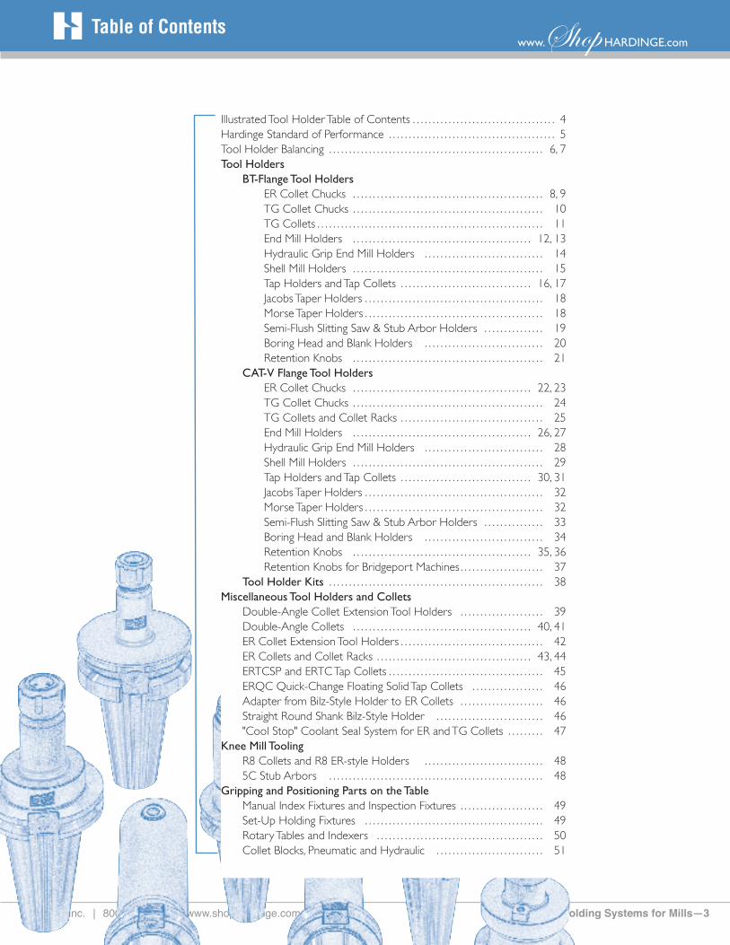
Illustrated Tool Holder Table of Contents ……………………………… 4Hardinge Standard of Performance …………………………………… 5Tool Holder Balancing ……………………………………………… 6, 7Tool Holders BT-Flange Tool Holders ER Collet Chucks ………………………………………… 8, 9 TG Collet Chucks ………………………………………… 10 TG Collets ………………………………………………… 11 End Mill Holders ……………………………………… 12, 13 Hydraulic Grip End Mill Holders ………………………… 14 Shell Mill Holders ………………………………………… 15 Tap Holders and Tap Collets …………………………… 16, 17 Jacobs Taper Holders ……………………………………… 18 Morse Taper Holders ……………………………………… 18 Semi-Flush Slitting Saw & Stub Arbor Holders …………… 19 Boring Head and Blank Holders ………………………… 20 Retention Knobs ………………………………………… 21 CAT-V Flange Tool Holders ER Collet Chucks ……………………………………… 22, 23 TG Collet Chucks ………………………………………… 24 TG Collets and Collet Racks ……………………………… 25 End Mill Holders ……………………………………… 26, 27 Hydraulic Grip End Mill Holders ………………………… 28 Shell Mill Holders ………………………………………… 29 Tap Holders and Tap Collets …………………………… 30, 31 Jacobs Taper Holders ……………………………………… 32 Morse Taper Holders ……………………………………… 32 Semi-Flush Slitting Saw & Stub Arbor Holders …………… 33 Boring Head and Blank Holders ………………………… 34 Retention Knobs ……………………………………… 35, 36 Retention Knobs for Bridgeport Machines ………………… 37 Tool Holder Kits ……………………………………………… 38Miscellaneous Tool Holders and Collets Double-Angle Collet Extension Tool Holders ………………… 39 Double-Angle Collets ……………………………………… 40, 41 ER Collet Extension Tool Holders ……………………………… 42 ER Collets and Collet Racks ………………………………… 43, 44 ERTCSP and ERTC Tap Collets ………………………………… 45 ERQC Quick-Change Floating Solid Tap Collets ……………… 46 Adapter from Bilz-Style Holder to ER Collets ………………… 46 Straight Round Shank Bilz-Style Holder ……………………… 46 "Cool Stop" Coolant Seal System for ER and TG Collets ……… 47 Knee Mill Tooling R8 Collets and R8 ER-style Holders ………………………… 48 5C Stub Arbors ……………………………………………… 48Gripping and Positioning Parts on the Table Manual Index Fixtures and Inspection Fixtures ………………… 49 Set-Up Holding Fixtures ……………………………………… 49 Rotary Tables and Indexers …………………………………… 50 Collet Blocks, Pneumatic and Hydraulic ……………………… 51

4—Precision Tool Holding Systems for Mills Hardinge Inc. | 800.843.8801 | www.shophardinge.com
Illustrated Tool Holder Table of Contents
* S & R (Strong & Rugged)
Collet Style
*
Solid Style
*
Retention Knobs – Pages 21, 35, 36, 37
Pages 8, 9, 22, 23
Pages 8, 9, 22, 23
Pages 8, 9, 22, 23
Pages 8, 9, 22, 23
Pages 8, 9, 22, 23
Pages 8, 9, 22, 23
Pages 10, 24
Pages 12, 13, 26, 27
Pages 14, 28
Pages 12, 26, 27
Pages 15, 29
Pages 16, 17, 30, 31
Pages 18, 32
Pages 18, 32
Pages 19, 33
Pages 20, 34
Pages 39, 42
Pages 39, 42

Hardinge Inc. | 800.843.8801 | www.shophardinge.com Precision Tool Holding Systems for Mills—5
www.Shop HARDINGE.comHardinge Standard of Performance
ER Collets collapse .040" from their nominal size. With this feature, fewer collets
are required to handle the full range of each holder. Collets are available in metric
or fractional sizes. Tap collets are also available. Our easy-to-read charts will help
you make your selections.
The ER and TG collet-style holders will hold drills, end mills, reamers, taps and bor-
ing bars, reducing the need for separate tool holders for each operation. Collet-style
holders are available in Stub, Standard, Extended, Extra-Extended and the massive
S&R (strong and rugged) configuration.
Quality & AccuracyHardinge’s AT-3 (and better) accuracy
for the shank taper on all tool holders
exceeds ANSI Standards by a minimum
of 35%. With a precision machine spindle,
such as those found on Hardinge and
Bridgeport machine tools, the holder
shanks and the spindle taper are precisely
mated. This assures the best TIR possible
and a stable holder, resulting in better
surface finishes, longer tool life and more
accurate workpieces.
It is necessary for the grind on the shank
of the holder to be uniform and have
an excellent surface finish. The latest
high-precision CNC grinding equipment
is used to ensure this consistency. If the
shanks have raised areas (or asperities),
the working forces common to machining
will weld the asperities to the spindle’s ID
taper. These will continually break off and
reform on both the spindle seat and the
tool shank surfaces which will cause pitting.
These metal particles turn into powder
and oxides – a process called fretting.
The extremely high precision grind on
our holder shanks resists fretting, which
results in longer life of the holders and
your machine’s spindle.
Tooling will be positioned on the cen-
terline of the spindle due to the precise
concentricity of the holders. This results
in accurate dimensions on your workpiece
and maximum productivity.
TG100 and TG150 Collets
Hardinge offers a full line of tool holders for the BT and CAT-V flange machine spindles. There are many different style holders including collet-style, shell mill, semi-flush slitting saw, stub arbor, tapping (floating and rigid), boring tool, Jacobs chuck, Morse taper, and blanks.
ER Colletsand ER Tap Collets

6—Precision Tool Holding Systems for Mills Hardinge Inc. | 800.843.8801 | www.shophardinge.com
Balancing
EXCELLENT
MARGINAL
POOR
Custom-engineered Tool Holder/Knob/Tool AssemblyPremium Balanced Tool Holders
Basic Balance Tool HoldersTypical Unbalanced Tool Holders
Tool life increases in relationship to the balance option selected.
Balanced ToolingWith the advent of higher spindle speeds, it is necessary to thoroughly understand the need for balanced tooling. When running at low spindle speeds, a slight imbalance of the tooling will not affect your machine tool’s spindle. However, as the rpm increases, this "slight" imbalance becomes considerable. As the imbalance increases, the amount of force (centrifu-gal) generated increases. When this force becomes high enough, the machine tool’s spindle can be damaged. This imbalance can also cause deflection of the tool and inaccuracies in the machining process. Take a look at the "Unbalanced Forces" chart shown below. The out-of-balance is
Do I need to balance the shell mills, taps, slitters, stub arbors, Jacobs chucks, Morse taper and boring head tool holders? No, unless they are used at high rpm. Generally, these holders are run at low rpm and balance is not a factor.
Can I use the standard unbalanced ER Collet Holders and End Mill Holders on my 10,000 rpm spindle? No, unless you are always running less than 6,000 rpm. The Basic Balance holder should be used on 10,000 rpm spindles and should also be used when machining above 6,000 rpm on 7,000 and 8,000 rpm spindles.
FAQ
FAQ
measured in g-mm (gram-millimeters) and the resulting force as the rpm increases is measured in in-lb (inch-pounds).
There are many factors which contribute to an imbalance in the tooling. The first is the balance of the holder itself and its assembled components (holder, reten-tion knob, nosepiece). We manufacture holders that will meet your balance requirements (see Balance Options) but there are other factors. Other factors include: the condition of the spindle taper - proper angle, damage (nicks, fret-ting, etc.); the condition of the holder’s taper (nicks, fretting, etc.) after the holder has been used; and the condition of the
tooling - adjustable boring holders, drill chucks, drills, end mills, boring bars. The assembly tolerance of the components of the tool holder (nosepiece, retention knob) are a factor of imbalance when the holder assembly was not balanced by the manufacturer. All of these factors must be at their optimum when doing high-speed machining. Like a chain, a balanced system is only as good as its weakest link. As the chart shows, balance is critical at the higher rpms.
Balance OptionsFortunately, our tool holders can be balanced to the speed you need. The latest balancing equipment is used to provide accurate balancing and quick turnaround. Leading machine tool builders highly recommend the use of accurately balanced holders for demanding high-speed applications. Our balancing team has years of experience and are com-mitted to providing you with properly balanced tool holders.
5,000 10,000 15,000 20,000 25,000
350
300
250
200
150
100
50
0
200 g-mm180 g-mm160 g-mm140 g-mm120 g-mm100 g-mm80 g-mm60 g-mm40 g-mm20 g-mm

Hardinge Inc. | 800.843.8801 | www.shophardinge.com Precision Tool Holding Systems for Mills—7
www.Shop HARDINGE.comBalance Options
Balance Options for Collet, End Mill, Hydraulicand Shell Mill Tool HoldersHardinge offers many balance options for the toolholder that requires balancing. When
placing the order, give the Hardinge representative the tool holder part number, the
balance option and the nosecap option if desired. If this option is not specified, you will
receive the standard tool holder with the standard nosecap.
Optional Nosecaps improve balance and/or holding power (replace standard nosecap)
Some of my drills and taps are spinning in the ER tool holders. Is there a way to get a better grip? Yes, use the ball bearing nosepiece. It allows almost twice the torque of the standard nosepiece. The ER Collet with a square will help with tap slippage (when combined with ball bearing nosepiece) for an even tighter grip.
NPBA Basic Balance Nosepiece
Standard nosepiece (precision balanced)
NPBB Ball Bearing Nosepiece
Almost doubles the holding power of the standard nosepiece
NPFB Fine Balance Nosepiece
Eliminates the inbalance of the standard-style
nosepiece
NPUB U-Balance Nosepiece
Includes eight small set screws which can be added or
removed to help balance the tool holder – this nose-piece
requires a balancing machine
FAQ
Option: Rating: Description:
None Standard Holder • Holders are not counterbalanced
BABA Basic Balance • Unequal drive slot depths, set screws, taper holders and other design asymmetries are counterbalanced
BAFH G2.5 @ 15,000 rpm • Counterbalances toolholder body design asymmetry – Includes balanced standard nosecap on collet chucks
BAFR G2.5 @ 15,000 rpm • Counterbalances toolholder body and retention knob asymmetry – Includes balanced standard nosecap on collet chucks
BATH G2.5 @ 20,000 rpm • Counterbalances toolholder body design asymmetry – Includes balanced standard nosecap on collet chucks
BATR G2.5 @ 20,000 rpm • Counterbalances toolholder body and retention knob asymmetry – Includes balanced standard nosecap on collet chucks
BAPB Premium Balance • Available for ER collet chucks and hydraulic end mill holders only • Certificate of Balance supplied • Counterbalances toolholder body, retention knob and collet with gage pin completely assembled • "Fine Balance" nosecap and choice of collet and gage pin • Parts are balanced individually and assembly is Certified to less than 3g-mm
BAPA Premium Adjustable • Available for ER Collet chucks and hydraulic end mill holders only – Balance Same as "Premium Balance" except includes U-Balance nosecap
BACU Custom Engineered • Designed to meet your individual requirement – consult Hardinge

8—Precision Tool Holding Systems for Mills Hardinge Inc. | 800.843.8801 | www.shophardinge.com
ER16 ER32ER25ER20ER11 ER32 S&R
Precision ER Collet Chucks — BT-Style Flange
Precision ER Holders – BT-Style Flange
STUB STANDARD EXTENDED
Style Taper Part No. B C D L Part No. B C D L Part No. B C D L
ER11 30 7961-30-02 3.00" .63" 1.90" 0.87"ER16 30 7962-30-01 2.00" 1.08" 2.05" 0.87" 7962-30-02 2.88" 1.08" 3.00" 0.87"ER20 30 7963-30-01 2.00" 1.26" 2.00" 0.87" 7963-30-02 3.00" 1.26" 2.90" 0.87"ER32 30 7965-30-01 2.15" 1.88" 2.10" 0.87" 7965-30-02 3.00" 1.88" 2.60" 0.87"ER11 35 7961-35-02 3.00" .63" 1.90" 0.87"ER16 35 7962-35-02 2.88" 1.08" 3.00" 0.87" 7962-35-03 4.88" 1.08" 3.00" 0.87"ER20 35 7963-35-02 3.00" 1.26" 3.30" 0.87" 7963-35-03 5.00" 1.26" 3.50" 0.87"ER32 35 7965-35-02 3.00" 1.88" 2.80" 0.87" 7965-35-03 5.00" 1.88" 4.00" 0.87"ER11 40 7961-40-02 3.00" .63" 1.80" 1.06"ER16 40 7962-40-02 2.88" 1.08" 3.00" 1.06" 7962-40-03 4.88" 1.08" 3.00" 1.06"ER20 40 7963-40-01 2.50" 1.26" 2.80" 1.06" 7963-40-02 4.00" 1.26" 3.50" 1.06" 7963-40-03 6.00" 1.26" 3.50" 1.06"ER25 40 7964-40-01 2.20" 1.65" 2.50" 1.06" 7964-40-02 4.00" 1.65" 3.50" 1.06" 7964-40-03 6.00" 1.65" 3.50" 1.06"ER32 40 7965-40-01 2.40" 1.88" 2.80" 1.06" 7965-40-02 4.00" 1.88" 4.00" 1.06" 7965-40-03 6.00" 1.88" 4.00" 1.06"ER16 45 7962-45-02 3.88" 1.08" 3.00" 1.31"ER20 45 7963-45-02 4.00" 1.26" 3.50" 1.31"ER32 45 7965-45-02 4.00" 1.88" 4.00" 1.31"ER16 50 7962-50-02 4.88" 1.08" 3.00" 1.50"ER20 50 7963-50-02 4.00" 1.26" 3.50" 1.50"ER32 50 7965-50-02 4.00" 1.88" 4.00" 1.50"
ER Collet Holders are available from ER11 to ER32 styles (.019" to .787" diameters). They are made to precision specification. Each style is concentric to the centerline within .0002". The flush precision nosepiece grips the tool close to the cutting edge for better ac-curacy. The shank taper accuracy for the holders is AT-3 or better. This style holder gives you the flexibility to mill, drill, ream, bore and tap.
Note: Retention knobs must be ordered separately for each holder; see page 21. Refer to page 47 for "Cool Stop" high-pressure coolant seals. For balance options; see pages 6 and 7.
Why shouldn’t I use end mills with Weldon flats in collet-style holders? Non-symmetrical tools should not be used in a collet-style holder. The Weldon flat makes the end mill unbalanced (non-symmetrical) resulting in poor finishes and possible spindle damage.FAQ
S & R SHANK
Style Taper Part No. B C D L
ER20R 40 7963-40-50 6.00" 1.25" 3.50" 1.06"ER32R 40 7965-40-50 6.00" 1.88" 4.00" 1.06"
S&R (Strong and Rugged)These extra-strong and rugged long tool holders steady the tool for smoother and faster cutting. Tools last longer due to the added mass of the holder - decreases vibration. Accepts double-ended end mills.

Hardinge Inc. | 800.843.8801 | www.shophardinge.com Precision Tool Holding Systems for Mills—9
www.Shop HARDINGE.com
Collets for ER Holders — see pages 43-44 for additional collet informationMetric Collets Fractional Collets Tap Collets – Split
Style Base Part No. Range Range Inches Base Part No. Range Base Part No. Range
ER11 1911-00-17- 1 mm to 07 mm .019" to .275" 1911-00-19- 1⁄16" to 1⁄4" — —ER16 1913-00-17- 1 mm to 10 mm .019" to .393" 1913-00-19- 1⁄16" to 13⁄32" 1913-00-18- #0 to 1⁄4" ER20 1915-00-17- 2 mm to 13 mm .039" to .511" 1915-00-19- 1⁄16" to 1⁄2" 1915-00-18- #8 to 1⁄2" ER25 2095-00-17- 2 mm to 16 mm .039" to .629" 2095-00-19- 1⁄16" to 5⁄8" 2095-00-18- #8 to 5⁄8" ER32 1917-00-17- 3 mm to 20 mm .078" to .787" 1917-00-19- 3⁄32" to 3⁄4" 1917-00-18- #8 to 13⁄16"
Stop Screws and Clips for ER Holders
Style
ER Standard Stop Screw Part No.
ER Standard Coolant 400psi
Stop Screw Part No.Thread Extractor Clips
Package of 10
ER11 — — — —ER16 7990-01-16-000004 7990-01-16-000006 7⁄16" - 20 7993-01-16-000007ER20 7990-01-20-000004 7990-01-20-000006 M14 - 1.5 7993-01-20-000007ER25 7990-01-25-000004 7990-01-25-000006 M18 - 1.5 7993-01-25-000007ER32 7990-01-32-000004 7990-01-32-000006 M22 - 1.5 7993-01-32-000007
ER Collet Chuck Accessories — BT-Style Flange
Additional ER-Style Collets are shown on page 46.
Nosepiece Caps and Wrenches for ER Collet Chuck Holders
Style
Taper
C Dia.
Standard Part No.
Ball Bearing Part No.
Wrench for Std. & Ball Bearing
Part No.
Fine Tune Part No.
U-Balance Part No.
Wrench for Fine & U-Bal. Part No.
ER11 All 0.63" 7991-01-11-000001 — 7992-01-11-000003 — — —ER16 All 1.08" 7991-01-16-000001 — 7992-01-16-000003 7991-01-16-000009 7991-01-16-000010 7992-01-16-000009ER20 All 1.26" 7991-01-20-000001 7991-01-20-000008 7992-01-20-000003 7991-01-20-000009 7991-01-20-000010 7992-01-20-000009ER25 All 1.65" 7991-01-25-000001 7991-01-25-000008 7992-01-25-000003 7991-01-25-000009 7991-01-25-000010 7992-01-25-000009ER32 All 1.88" 7991-01-32-000001 7991-01-32-000008 7992-01-32-000003 7991-01-32-000009 7991-01-32-000010 7992-01-32-000009
Quick-Change Floating Solid Tap Collets Style Base Part No. Range ERQC16 2143-00-18- #0 - #10 ERQC20 2145-00-18- #0 - 1⁄4" ERQC25 2147-00-18- #0 - 1⁄2" ERQC32 2149-00-18- #0 - 9⁄16"
Floating Solid Tap Collets Style Base Part No. Range ERTC16 1921-00-18- #0 - #10 ERTC20 1923-00-18- #0 - 1⁄4" ERTC25 2097-00-18- #0 - 1⁄2" ERQC32 2099-00-18- #8 - 5⁄8"
C C C C
UrethaneSeal
Additional ER-Style Collets are shown on page 45.

10—Precision Tool Holding Systems for Mills Hardinge Inc. | 800.843.8801 | www.shophardinge.com
Stop Screws for TG Holders
Style
ThreadTG Stop Screw
Standard Part No.TG Stop Screw Coolant
400 psi Part No.TG100 11⁄8" x 16 7990-02-10-000004 7990-02-10-000006TG150 13⁄8" x 12 7990-02-15-000004 7990-02-15-000006TG150 15⁄8" x 12 7990-02-15-000014 7990-02-15-000016
Nosepiece and Wrench for TG Holders
Style
TaperC
DiameterTG Nosepiece
Part No.WrenchPart No.
TG100 All 2.50" 7991-02-10-000014 7992-02-10-000003TG150 All 3.50" 7991-02-15-000015 7992-02-15-000003
Precision TG Collet Chucks — BT-Style Flange
TG collets have a shallow single-angle to ensure precise concentricity between the collet, the holder and the tool. The nosepiece associated with the TG holder incorporates a rotating ball assembly with a radial float. The accuracy of this system is unsurpassed by any other. Coolant seals are shown on page 47.
UrethaneSeal
Standard TG Collets
StyleInch
Part No.Range
1/64" IncrementsMetric
Part No. Range
TG100 1905-00-19- 3⁄32" to 1" 1905-00-17- 6.0mm to 25.5mmTG150 1909-00-19- 1⁄2" to 11⁄2" 1909-00-17- 12.mm to 38.0mm
See the next page for the full range of TG Collets and part numbers.
TG Collet Holders are available for TG100 and TG150 (.093" to 1.5" diameter) collets. The TG Holders have a flush nosepiece design in-corporating a rotating ball assembly which produces a radial float. This, in turn, forces the collet to self-center for maximum grip, precision and extended tool life. Retention knobs must be ordered separately for each holder; see page 21. Refer to page 47 for "Cool Stop" high-pressure coolant seals. For balance options; see pages 6 and 7. Maximum recommended torque is 60 ft-lb – DO NOT OVER-TORQUE.
Precision TG Holders – BT-Style FlangeSTANDARD EXTENDED STANDARD EXTENDED
Style Taper Part No. B C D L Part No. B C D L Stop Screw Stop Screw
TG100 30 7959-30-02 4.00" 2.50" 2.7" .87" — — — — — 7990-02-10-000004 —TG100 35 7959-35-02 3.50" 2.50" 2.9" .87" 7959-35-03 5.47" 2.50" 4.6" .87" 7990-02-10-000004 7990-02-10-000004TG100 40 7959-40-02 3.50" 2.50" 3.1" 1.06" 7959-40-03 5.50" 2.50" 5.0" 1.06" 7990-02-10-000004 7990-02-10-000004TG150 40 7960-40-02 4.78" 3.50" 3.8" 1.06" — — — — — 7990-02-15-000004 —TG100 45 7959-45-02 3.50" 2.50" 4.1" 1.31" 7959-45-03 6.00" 2.50" 5.0" 1.31" 7990-02-10-000004 7990-02-10-000004TG150 45 7960-45-02 4.00" 3.50" 4.4" 1.31" 7960-45-03 6.00" 3.50" 5.0" 1.31" 7990-02-15-000004 7990-02-15-000014TG100 50 7959-50-02 3.50" 2.50" 4.4" 1.50" 7959-50-03 6.00" 2.50" 5.0" 1.50" 7990-02-10-000004 7990-02-10-000004TG150 50 7960-50-02 3.50" 3.50" 4.5" 1.50" 7960-50-03 6.00" 3.50" 5.0" 1.50" 7990-02-15-000014 7990-02-15-000014
TG Collet RacksTG100 TG150
Part No. 0946-10-00-000035 0946-15-00-000025Capacity 35 TG100 Collets 25 TG150 Collets
TG100
TG150

Hardinge Inc. | 800.843.8801 | www.shophardinge.com Precision Tool Holding Systems for Mills—11
www.Shop HARDINGE.comHigh-Precision Single-Angle TG Collets
TG Collets — Inch Inch TG100 Part Number Inch TG150 Part Number3/32" 1905-00-19-000937 1⁄2" 1909-00-19-0050007/64" 1905-00-19-001093 33⁄64" 1909-00-19-0051561/8" 1905-00-19-001250 17⁄32" 1909-00-19-0053129/64" 1905-00-19-001406 35⁄64" 1909-00-19-0054685/32" 1905-00-19-001562 9⁄16" 1909-00-19-00562511/64" 1905-00-19-001718 37⁄64" 1909-00-19-0057813/16" 1905-00-19-001875 19⁄32" 1909-00-19-00593713/64" 1905-00-19-002031 39⁄64" 1909-00-19-0060937/32" 1905-00-19-002187 5⁄8" 1909-00-19-00625015/64" 1905-00-19-002343 41⁄64" 1909-00-19-0064061/4" 1905-00-19-002500 21⁄32" 1909-00-19-006562
17/64" 1905-00-19-002656 43⁄64" 1909-00-19-0067189/32" 1905-00-19-002812 11⁄16" 1909-00-19-00687519/64" 1905-00-19-002968 45⁄64" 1909-00-19-0070315/16" 1905-00-19-003125 23⁄32" 1909-00-19-00718721/64" 1905-00-19-003281 47⁄64" 1909-00-19-00734311/32" 1905-00-19-003437 3⁄4" 1909-00-19-00750023/64" 1905-00-19-003593 49⁄64" 1909-00-19-0076563/8" 1905-00-19-003750 25⁄32" 1909-00-19-007812
25⁄64" 1905-00-19-003906 51⁄64" 1909-00-19-00796813⁄32" 1905-00-19-004062 13⁄16" 1909-00-19-00812527⁄64" 1905-00-19-004218 53⁄64" 1909-00-19-0082817⁄16" 1905-00-19-004375 27⁄32" 1909-00-19-00843729⁄64" 1905-00-19-004531 55⁄64" 1909-00-19-00859315⁄32" 1905-00-19-004687 7⁄8" 1909-00-19-00875031⁄64" 1905-00-19-004843 57⁄64" 1909-00-19-008906
1⁄2" 1905-00-19-005000 29⁄32" 1909-00-19-00906233⁄64" 1905-00-19-005156 59⁄64" 1909-00-19-00921817⁄32" 1905-00-19-005312 15⁄16" 1909-00-19-00937535⁄64" 1905-00-19-005468 61⁄64" 1909-00-19-009531 9⁄16" 1905-00-19-005625 31⁄32" 1909-00-19-00968737⁄64" 1905-00-19-005781 63⁄64" 1909-00-19-00984319⁄32" 1905-00-19-005937 1" 1909-00-19-01000039⁄64" 1905-00-19-006093 11⁄64" 1909-00-19-010156
5⁄8" 1905-00-19-006250 11⁄32" 1909-00-19-01031241⁄64" 1905-00-19-006406 13⁄64" 1909-00-19-01046821⁄32" 1905-00-19-006562 11⁄16" 1909-00-19-01062543⁄64" 1905-00-19-006718 15⁄64" 1909-00-19-01078111⁄16" 1905-00-19-006875 13⁄32" 1909-00-19-01093745⁄64" 1905-00-19-007031 17⁄64" 1909-00-19-01109323⁄32" 1905-00-19-007187 11⁄8" 1909-00-19-01125047⁄64" 1905-00-19-007343 19⁄64" 1909-00-19-011406
3⁄4" 1905-00-19-007500 13⁄16" 1909-00-19-01156249⁄64" 1905-00-19-007656 111⁄64" 1909-00-19-01171825⁄32" 1905-00-19-007812 13⁄16" 1909-00-19-01187551⁄64" 1905-00-19-007968 113⁄64" 1909-00-19-01203113⁄16" 1905-00-19-008125 17⁄32" 1909-00-19-01218753⁄64" 1905-00-19-008281 115⁄64" 1909-00-19-01234327⁄32" 1905-00-19-008437 11⁄4" 1909-00-19-01250055⁄64" 1905-00-19-008593 117⁄64" 1909-00-19-012656
7⁄8" 1905-00-19-008750 19⁄32" 1909-00-19-01281257⁄64" 1905-00-19-008906 119⁄64" 1909-00-19-01296829⁄32" 1905-00-19-009062 15⁄16" 1909-00-19-01312559⁄64" 1905-00-19-009218 121⁄64" 1909-00-19-01328115⁄16" 1905-00-19-009375 111⁄32" 1909-00-19-01343761⁄64" 1905-00-19-009531 123⁄64" 1909-00-19-01359331⁄32" 1905-00-19-009687 13⁄8" 1909-00-19-01375063⁄64" 1905-00-19-009843 125⁄64" 1909-00-19-0139061" 1905-00-19-010000 113⁄32" 1909-00-19-014062
127⁄64" 1909-00-19-01421817⁄16" 1909-00-19-014375129⁄64" 1909-00-19-014531115⁄32" 1909-00-19-014687131⁄64" 1909-00-19-01484311⁄2" 1909-00-19-015000
TG Collet SetsPart Numbers Qty. Range & Increment
TG100 0932-00-19-000059 59 3⁄32" to 1" (1⁄64" Incr.)TG100 0932-00-19-000041 41 3⁄8" to 1" (1⁄64" Incr.)TG100 0932-00-19-000030 30 3⁄32" to 1" (1⁄32" Incr.)TG100 0932-00-19-000021 21 3⁄8" to 1" (1⁄32" Incr.)TG150 0934-00-19-000065 65 1⁄2" to 11⁄2" (1⁄64" Incr.)TG150 0934-00-19-000033 33 1⁄2" to 11⁄2" (1⁄32" Incr.)TG150 0934-00-19-000017 17 1⁄2" to 11⁄2" (1⁄16" Incr.)
TG Collets — Metricmm TG100 Part Number TG150 Part Number6.0 1905-00-17-060000 12.0 1909-00-17-1200006.5 1905-00-17-065000 12.5 1909-00-17-1250007.0 1905-00-17-070000 13.0 1909-00-17-1300007.5 1905-00-17-075000 13.5 1909-00-17-1350008.0 1905-00-17-080000 14.0 1909-00-17-1400008.5 1905-00-17-085000 14.5 1909-00-17-1450009.0 1905-00-17-090000 15.0 1909-00-17-1500009.5 1905-00-17-095000 15.5 1909-00-17-15500010.0 1905-00-17-100000 16.0 1909-00-17-16000010.5 1905-00-17-105000 16.5 1909-00-17-16500011.0 1905-00-17-110000 17.0 1909-00-17-17000011.5 1905-00-17-115000 17.5 1909-00-17-17500012.0 1905-00-17-120000 18.0 1909-00-17-18000012.5 1905-00-17-125000 18.5 1909-00-17-18500013.0 1905-00-17-130000 19.0 1909-00-17-19000013.5 1905-00-17-135000 19.5 1909-00-17-19500014.0 1905-00-17-140000 20.0 1909-00-17-20000014.5 1905-00-17-145000 20.5 1909-00-17-205000 15.0 1905-00-17-150000 21.0 1909-00-17-21000015.5 1905-00-17-155000 21.5 1909-00-17-21500016.0 1905-00-17-160000 22.0 1909-00-17-22000016.5 1905-00-17-165000 22.5 1909-00-17-22500017.0 1905-00-17-170000 23.0 1909-00-17-23000017.5 1905-00-17-175000 23.5 1909-00-17-23500018.0 1905-00-17-180000 24.0 1909-00-17-24000018.5 1905-00-17-185000 24.5 1909-00-17-24500019.0 1905-00-17-190000 25.0 1909-00-17-25000019.5 1905-00-17-195000 25.5 1909-00-17-25500020.0 1905-00-17-200000 26.0 1909-00-17-26000020.5 1905-00-17-205000 26.5 1909-00-17-26500021.0 1905-00-17-210000 27.0 1909-00-17-27000021.5 1905-00-17-215000 27.5 1909-00-17-27500022.0 1905-00-17-220000 28.0 1909-00-17-28000022.5 1905-00-17-225000 28.5 1909-00-17-28500023.0 1905-00-17-230000 29.0 1909-00-17-29000023.5 1905-00-17-235000 29.5 1909-00-17-29500024.0 1905-00-17-240000 30.0 1909-00-17-30000024.5 1905-00-17-245000 30.5 1909-00-17-30500025.0 1905-00-17-250000 31.0 1909-00-17-31000025.5 1905-00-17-255000 31.5 1909-00-17-315000
32.0 1909-00-17-32000032.5 1909-00-17-32500033.0 1909-00-17-33000033.5 1909-00-17-33500034.0 1909-00-17-34000034.5 1909-00-17-34500035.0 1909-00-17-35000035.5 1909-00-17-35500036.0 1909-00-17-36000036.5 1909-00-17-36500037.0 1909-00-17-37000037.5 1909-00-17-37500038.0 1909-00-17-380000

12—Precision Tool Holding Systems for Mills Hardinge Inc. | 800.843.8801 | www.shophardinge.com
40-TAPER STUB 40-TAPER STANDARD
40-TAPER EXTENDED
A Taper Part No. B C D L Part No. B C D L Part No. B C D L
0.125" 40 7951-40-02-001250 2.50" 0.69" 3.8" 1.06"0.187" 40 7951-40-02-001875 2.50" 0.69" 2.4" 1.06"0.250" 40 7951-40-02-002500 2.50" 0.78" 2.4" 1.06"0.312" 40 7951-40-02-003125 2.50" 0.88" 3.8" 1.06"0.375" 40 7951-40-02-003750 2.50" 1.00" 2.4" 1.06" 7951-40-03-003750 4.00" 1.00" 3.9" 1.06"0.437" 40 7951-40-02-004375 2.50" 1.13" 3.8" 1.06"0.500" 40 7951-40-01-005000 1.25" 1.25" 1.8" 1.06" 7951-40-02-005000 2.50" 1.25" 2.4" 1.06" 7951-40-03-005000 4.00" 1.25" 3.9" 1.06"0.562" 40 7951-40-02-005625 2.50" 1.38" 3.0" 1.06"0.625" 40 7951-40-01-006250 1.38" 1.50" 2.4" 1.06" 7951-40-02-006250 2.50" 1.57" 3.6" 1.06" 7951-40-03-006250 4.00" 1.50" 3.6" 1.06"0.750" 40 7951-40-01-007500 1.44" 1.75" 2.5" 1.06" 7951-40-02-007500 2.50" 1.75" 3.9" 1.06" 7951-40-03-007500 4.00" 1.75" 3.9" 1.06"0.875" 40 7951-40-02-008750 3.50" 1.88" 4.2" 1.06" 7951-40-03-008750 5.00" 1.88" 4.2" 1.06"1.000" 40 7951-40-01-010000 2.50" 2.00" 2.5" 1.06" 7951-40-02-010000 3.75" 2.00" 4.4" 1.06" 7951-40-03-010000 5.00" 2.00" 4.4" 1.06"1.250" 40 7951-40-01-012500 2.50" 2.49" 2.5" 1.06" 7951-40-02-012500 3.75" 2.50" 4.0" 1.06" 7951-40-03-012500 5.00" 2.50" 4.0" 1.06"1.500" 40 7951-40-02-015000 4.25" 2.50" 4.0" 1.06"
End Mill Holders 30- and 40-Taper – BT-Style Flange
30-TAPER STANDARD 35-TAPER STANDARD
A Taper Part No. B C D L A Taper Part No. B C D L
0.125" 30 7951-30-02-001250 2.50" 0.69" 3.3" 0.87" 0.187" 35 7951-35-02-001875 2.50" 0.69" 3.6" 0.87"0.187" 30 7951-30-02-001875 2.50" 0.69" 3.3" 0.87" 0.250" 35 7951-35-02-002500 2.50" 0.78" 3.6" 0.87"0.250" 30 7951-30-02-002500 2.50" 0.78" 3.3" 0.87" 0.375" 35 7951-35-02-003750 2.50" 1.00" 2.2" 0.87"0.312" 30 7951-30-02-003125 2.50" 0.88" 3.3" 0.87" 0.500" 35 7951-35-02-005000 2.50" 1.25" 3.0" 0.87"0.375" 30 7951-30-02-003750 2.50" 1.00" 3.3" 0.87" 0.625" 35 7951-35-02-006250 2.50" 1.50" 3.6" 0.87"0.437" 30 7951-30-02-004375 2.50" 1.13" 2.0" 0.87" 0.750" 35 7951-35-02-007500 2.50" 1.75" 3.9" 0.87"0.500" 30 7951-30-02-005000 2.50" 1.25" 3.1" 0.87" 0.875" 35 7951-35-02-008750 3.50" 1.88" 4.2" 0.87"0.562" 30 7951-30-02-005625 2.50" 1.38" 3.0" 0.87" 1.000" 35 7951-35-02-010000 3.50" 2.00" 4.4" 0.87"0.625" 30 7951-30-02-006250 2.75" 1.57" 3.6" 0.87" 1.250" 35 7951-35-02-012500 4.00" 2.50" 3.8" 0.87"0.750" 30 7951-30-02-007500 3.00" 1.75" 3.7" 0.87"
End Mill Holders — BT-Style Flange
End Mill Holders are offered in stub, standard, extended and S & R (strong & rugged) models. The fine pitch set screws (included) match Weldon f lats to firmly lock the end mill. All holders, except the stub holders from 1⁄8" up to 1" diameter, can accept single- or double-end tools. The stub holder will only accept single-end tools. Holders for end mills 1" and larger have two locking screws (except the stub). The locking screws are aligned with the drive slot for your convenience. End mills without Weldon flats should not be used in these holders.
Retention knobs must be ordered separately for each holder; refer to page 21. For balance options; see pages 6 and 7. Holders for metric tools are available on application.
40-TAPER S & R SHANK
Style Taper Part No. B C D L
0.375" 40 7951-40-50-003750 6.00" 1.00" 7.3" 1.06"0.500" 40 7951-40-50-005000 6.00" 1.25" 7.3" 1.06"0.625" 40 7951-40-50-006250 6.00" 1.50" 3.6" 1.06"0.750" 40 7951-40-50-007500 6.00" 1.75" 3.9" 1.06"
S&R (Strong and Rugged)These extra strong and rugged long tool holders steady the tool for smoother and faster cutting. Tools last longer due to the added mass of the holder - decreases vibration. Accepts double-ended end mills.

Hardinge Inc. | 800.843.8801 | www.shophardinge.com Precision Tool Holding Systems for Mills—13
www.Shop HARDINGE.com
50-TAPER STANDARD
50-TAPER EXTENDED
A Taper Part No. B C D L Part No. B C D L
0.375" 50 7951-50-02-003750 3.00" 1.00" 3.7" 1.50" 7951-50-03-003750 6.00" 1.00" 6.7" 1.50"0.500" 50 7951-50-02-005000 3.00" 1.25" 3.7" 1.50" 7951-50-03-005000 6.00" 1.25" 6.7" 1.50"0.625" 50 7951-50-02-006250 3.00" 1.50" 3.7" 1.50" 7951-50-03-006250 6.00" 1.50" 6.7" 1.50"0.750" 50 7951-50-02-007500 3.00" 1.75" 3.7" 1.50" 7951-50-03-007500 6.00" 1.75" 6.7" 1.50"0.875" 50 7951-50-02-008750 4.00" 1.88" 4.2" 1.50" 7951-50-03-008750 6.00" 1.88" 4.2" 1.50"1.000" 50 7951-50-02-010000 4.25" 2.00" 4.4" 1.50" 7951-50-03-010000 6.00" 2.00" 4.4" 1.50"1.250" 50 7951-50-02-012500 4.25" 2.50" 4.0" 1.50" 7951-50-03-012500 6.00" 2.50" 4.0" 1.50"1.500" 50 7951-50-02-015000 4.25" 2.50" 4.0" 1.50" 7951-50-03-015000 6.00" 2.50" 4.0" 1.50"2.000" 50 7951-50-02-020000 5.00" 3.75" 5.0" 1.50" 7951-50-03-020000 6.00" 3.75" 5.0" 1.50"
End Mill Holders 45- and 50-Taper – BT-Style Flange 45-TAPER STANDARD
45-TAPER EXTENDED
A Taper Part No. B C D L Part No. B C D L
0.375" 45 7951-45-02-003750 3.00" 1.00" 3.2" 1.31" 7951-45-03-003750 5.00" 1.00" 5.2" 1.31"0.500" 45 7951-45-02-005000 3.00" 1.25" 3.2" 1.31" 7951-45-03-005000 5.00" 1.25" 5.2" 1.31"0.625" 45 7951-45-02-006250 3.00" 1.50" 3.2" 1.31" 7951-45-03-006250 5.00" 1.50" 5.2" 1.31"0.750" 45 7951-45-02-007500 3.00" 1.75" 3.9" 1.31" 7951-45-03-007500 5.00" 1.75" 5.2" 1.31"0.875" 45 7951-45-02-008750 4.00" 1.88" 4.2" 1.31" 7951-45-03-008750 6.00" 1.88" 4.2" 1.31"1.000" 45 7951-45-02-010000 4.00" 2.00" 4.4" 1.31" 7951-45-03-010000 6.00" 2.00" 4.4" 1.31"1.250" 45 7951-45-02-012500 4.00" 2.50" 4.0" 1.31" 7951-45-03-012500 6.00" 2.50" 4.0" 1.31"1.500" 45 7951-45-02-015000 4.00" 2.50" 4.0" 1.31" 7951-45-03-015000 6.00" 2.50" 4.0" 1.31"
End Mill Holders & Accessories — BT-Style Flange
Replacement Locking ScrewsA Part No. Thread Size Length Torque (in-lb)
0.125" 7990-12-45-000008 8 - 32 .25" 180.187" 7990-12-45-000010 10 - 32 .25" 300.250" 7990-12-45-002500 1⁄4" - 28 .25" 600.312" 7990-12-45-003125 5⁄16" - 24 .25" 1200.375" 7990-12-45-003750 3⁄8" - 24 .25" 2000.500" 7990-12-45-004375 7⁄16" - 20 .36" 2200.625" 7990-12-45-005000 1⁄2" - 20 .42" 5000.750" 7990-12-45-006250 5⁄8" - 18 .49" 5600.875" 7990-12-45-006250 5⁄8" - 18 .49" 5601.000" 7990-12-45-007500 3⁄4" - 16 .45" 11501.250" 7990-12-45-007500 3⁄4" - 16 .45" 11501.500" 7990-12-45-007500 3⁄4" - 16 .45" 11502.000" 7990-12-45-010000 1" - 14 .88" 1500
End Mill Holders are offered in stub, standard, extended and S & R (strong & rugged) models. The fine pitch set screws (included) match Weldon f lats to firmly lock the end mill. All holders, except the stub holders from 1⁄8" up to 1" diameter, can accept single- or double-end tools. The stub holder will only accept single-end tools. Holders for end mills 1" and larger have two locking screws (except the stub). The locking screws are aligned with the drive slot for your convenience. End mills without Weldon flats should not be used in these holders.Retention knobs must be ordered separately for each holder; refer to page 21. For balance options; see pages 6 and 7. Holders for metric tools are available on application.

14—Precision Tool Holding Systems for Mills Hardinge Inc. | 800.843.8801 | www.shophardinge.com
End Mill Holders, Hydraulic Grip — BT-Style Flange
Hydraulic clamping ensures high-torque gripping of the end mill. The complete circum-ference of the end mill is gripped, which eliminates the need for special seals. Precision balance is assured when using end mills without flats. The hydraulic chamber is completely enclosed, eliminating any possibility of contamination from coolant and dirt. The unique design of this holder provides excellent gripping over the long haul. Hydraulic End Mill Holders are for precision work (not for roughing) and for end mills with one cutting end.Retention knobs must be ordered separately for each holder; see page 21. For balance options; see pages 6 and 7. Stop screws are sold separately. Metric sizes available on application.
Benefits:
• Powerful hydraulic grip
• Radial repeatability of ±.00008" (.0020 mm)
• Vibration damping for chatter-free machining
• Full radial grip on tool’s diameter with greater gripping power than competitive holders
• Repetitive balance for high spindle speeds
• High gripping force provides a smooth and secure torque transmission to the cutting tool
• Ability to grip the end mill’s shank with or without flats - high-speed operations require end mills with no flats
• Standard through-the-spindle coolant
• Holders for metric tools are available on application
End Mill Holders, Hydraulic Grip — BT-Style FlangeA Taper Part No. B B1 B3 C C1
0.500" 40 7953-40-02-005000 4.000" 1.094" 2.936" 1.750" 1.404"0.625" 40 7953-40-02-006250 4.000" 1.088" 2.936" 1.875" 1.500"0.750" 40 7953-40-02-007500 4.000" 1.094" 2.936" 2.000" 1.638"1.000" 40 7953-40-02-010000 4.000" 1.164" 2.936" 2.250" 1.967"
Stop ScrewsStyle Part No. Thread
All 7990-13-45-160000 M16-20

Hardinge Inc. | 800.843.8801 | www.shophardinge.com Precision Tool Holding Systems for Mills—15
www.Shop HARDINGE.comShell Mill Holders — BT-Style Flange
Shell Mill Holders are manufactured to precision tolerances. The pilot diameter is ground to fit the bore of the shell mill and is concentric to the centerline of the holder’s shank. The locating face is perpendicular to the centerline within .0002". A cap screw and two removable drive keys come standard with each holder. 2" Shell Mill Holders have four 5/8"-11 threaded holes on a 4" bolt circle.
Retention knobs must be ordered separately for each holder; see page 21. For balance options; see pages 6 and 7. Holders for metric tools are available on application.
Drive Keys
Cap Screws
Shell Mill Holders – BT-Style Flange
STANDARD EXTENDED
A Taper Part No. B C L Part No. B C L
0.750" 30 7954-30-02-007500 1.75" 1.69" .87" — — — —1.000" 30 7954-30-02-010000 2.00" 2.19" .87" — — — —0.750" 35 7954-35-02-007500 1.18" 1.69" .87" 7954-35-03-075000 4.72" 1.69" .87"1.000" 35 7954-35-02-010000 1.26" 2.19" .87" 7954-35-03-010000 4.72" 2.19" .87"1.250" 35 7954-35-02-012500 2.36" 2.75" .87" — — — —0.750" 40 7954-40-02-007500 1.77" 1.69" 1.06" 7954-40-03-007500 4.13" 1.69" 1.06"1.000" 40 7954-40-02-010000 1.77" 2.19" 1.06" 7954-40-03-010000 4.13" 2.19" 1.06"1.250" 40 7954-40-02-012500 1.81" 2.75" 1.06" 7954-40-03-012500 4.13" 2.75" 1.06"1.500" 40 7954-40-02-015000 2.36" 3.81" 1.06" 7954-40-03-015000 4.72" 3.81" 1.06"0.750" 45 7954-45-02-007500 1.77" 1.69" 1.31" 7954-45-03-007500 4.13" 1.69" 1.31"1.000" 45 7954-45-02-010000 1.77" 2.19" 1.31" 7954-45-03-010000 4.13" 2.19" 1.31"1.250" 45 7954-45-02-012500 1.77" 2.75" 1.31" 7954-45-03-012500 4.13" 2.75" 1.31"1.500" 45 7954-45-02-015000 2.36" 3.81" 1.31" 7954-45-03-015000 4.13" 3.81" 1.31"2.000" 45 7954-45-02-020000 2.75" 4.88" 1.31" 7954-45-03-020000 4.72" 4.88" 1.31"1.000" 50 7954-50-02-010000 1.75" 2.19" 1.50" 7954-50-03-010000 4.00" 2.19" 1.50"1.250" 50 7954-50-02-012500 1.75" 2.75" 1.50" 7954-50-03-012500 4.00" 2.75" 1.50"1.500" 50 7954-50-02-015000 1.75" 3.81" 1.50" 7954-50-03-015000 4.00" 3.81" 1.50"2.000" 50 7954-50-02-020000 3.00" 4.88" 1.50" 7954-50-03-020000 4.00" 4.88" 1.50"
Drive Keys and Cap ScrewsPilot Diameter Drive Key Part No. A B Cap Screw Part No. A B
.750" 7993-10-09-003125 5⁄16" .156" 7990-10-45-008750 7⁄8" 3⁄8" - 241.000" 7993-10-09-003750 3⁄8" .187" 7990-10-45-011875 13⁄16" 1⁄2" - 201.250" 7993-10-09-005000 1⁄2" .250" 7990-10-45-015000 11⁄2" 5⁄8" - 181.500" 7993-10-09-006250 5⁄8" .312" 7990-10-45-018750 17⁄8" 3⁄4" - 162.000" 7993-10-09-007500 3⁄4" .375" 7990-10-45-025000 21⁄2" 1" - 14

16—Precision Tool Holding Systems for Mills Hardinge Inc. | 800.843.8801 | www.shophardinge.com
Heavy-Duty Tap Holders and Tap Collets — BT-Style Flange
This Tension/Compression floating Tap Holder accommo-dates feeding errors. Maximum pull out of .750" and compres-sion of .370".
L
Size Diameter . Length .#1 .75" (19mm) 1.12" (28.44mm)#2 1.22" (31mm) 1.81" (45.97mm)#3 1.89" (48mm) 2.74" (70.00mm)
This Heavy-duty Rigid Tap Holder is for use on newer machine tools that have syn-chronous capabilities.
Tension/Compression and Rigid Tap Holders STANDARD TAP HOLDER TENSION COMPRESSION
STANDARD TAP HOLDER RIGID SYNCHRONOUS
EXTENDED TAP HOLDER RIGID SYNCHRONOUS
Taper Collet Size Part No. B* C L Part No. B* C L Part No. B* C L
30 #1 7955-30-02-000001 4.95" 1.75" .87" 7956-30-02-000001 3.07" 1.50" .87" — — — —35 #1 7955-35-02-000001 4.68" 1.75" .87" 7956-35-02-000001 3.12" 1.50" .87" — — — —35 #2 7955-35-02-000002 6.72" 2.25" .87" 7956-35-02-000002 3.82" 1.88" .87" — — — —40 #1 7955-40-02-000001 4.53" 1.75" 1.06" 7956-40-02-000001 3.31" 1.50" 1.06" 7956-40-03-000001 5.87" 1.50" 1.06"40 #2 7955-40-02-000002 6.72" 2.25" 1.06" 7956-40-02-000002 4.01" 1.88" 1.06" 7956-40-03-000002 6.57" 1.88" 1.06"45 #1 7955-45-02-000001 4.53" 1.75" 1.31" 7956-45-02-000001 3.56" 1.50" 1.31" 7956-45-03-000001 6.87" 1.50" 1.31"45 #2 7955-45-02-000002 6.72" 2.25" 1.31" 7956-45-02-000002 4.26" 1.88" 1.31" 7956-45-03-000002 7.57" 1.88" 1.31"45 #3 7955-45-02-000003 8.33" 3.25" 1.31" — — — — 7956-45-03-000003 8.33" 3.25" 1.31"50 #1 7955-50-02-000001 4.64" 1.75" 1.50" 7956-50-02-000001 3.75" 1.50" 1.50" 7956-50-03-000001 7.87" 1.50" 1.50"50 #2 7955-50-02-000002 6.72" 2.25" 1.50" 7956-50-02-000002 4.45" 1.88" 1.50" 7956-50-03-000002 8.57" 1.88" 1.50"50 #3 7955-50-02-000003 8.33" 3.25" 1.50" — — — — 7956-50-03-000003 8.33" 3.25" 1.50"
Quick-Change Tap Collets — InchCollet Size #1 Collet Size #2 Collet Size #3
Part Number Shank Dia.
Square Tap Size Part Number Shank Dia.
Square Tap Size Part Number Shank Dia.
Square Tap Size
7989-51-11-001410 0.141" 0.110" #0-#6 7989-51-12-003180 0.318" 0.238" 5⁄16" 7989-51-13-006520 0.652" 0.489" 13⁄16"7989-51-11-001680 0.168" 0.131" #8 7989-51-12-003810 0.381" 0.286" 3⁄8" 7989-51-13-006970 0.697" 0.523" 7⁄8"7989-51-11-001940 0.194" 0.152" #10 7989-51-12-003230 0.323" 0.242" 7⁄16" 7989-51-13-007600 0.760" 0.570" 15⁄16"7989-51-11-002200 0.220" 0.165" #12 7989-51-12-003670 0.367" 0.275" 1⁄2" 7989-51-13-008000 0.800" 0.600" 1"7989-51-11-002550 0.255" 0.191" 1⁄4" 7989-51-12-004290 0.429" 0.322" 9⁄16" 7989-51-13-008960 0.896" 0.672" 11⁄8"7989-51-11-003180 0.318" 0.238" 5⁄16" 7989-51-12-004800 0.480" 0.360" 5⁄8" 7989-51-13-010210 1.021" 0.766" 11⁄4"7989-51-11-003810 0.381" 0.286" 3⁄8" 7989-51-12-005420 0.542" 0.406" 11⁄16" 7989-51-13-011080 1.108" 0.831" 13⁄8"7989-51-11-003230 0.323" 0.242" 7⁄16" 7989-51-12-005900 0.590" 0.442" 3⁄4" 7989-51-13-007000 0.700" 0.531" 3⁄8" Pipe7989-51-11-003670 0.367" 0.275" 1⁄2" 7989-51-12-006520 0.652" 0.489" 13⁄16" 7989-51-13-006870 0.687" 0.515" 1⁄2" Pipe7989-51-11-004290 0.429" 0.322" 9⁄16" 7989-51-12-006970 0.697" 0.523" 7⁄8" 7989-51-13-009060 0.906" 0.679" 3⁄4" Pipe7989-51-11-003130 0.313" 0.234" 1⁄16" Pipe 7989-51-12-005620 0.562" 0.421" 1⁄4" Pipe 7989-51-13-011250 1.125" 0.843" 1" Pipe7989-51-11-004370 0.437" 0.328" 1⁄8" Pipe 7989-51-12-007000 0.700" 0.531" 3⁄8" Pipe
7989-51-12-006870 0.687" 0.515" 1⁄2" Pipe7989-51-11-000002 Kit of 12 Collets 7989-51-12-000002 Kit of 13 Collets 7989-51-13-000002 Kit of 11 Collets
Metric collets are made to the DIN standard – ANSI standard metric taps (the standard common in the United States) cannot be used in these collets – Refer to chart below for ANSI Metric tap shank sizes for use in Inch collets. See Brochure 2351 for additional Tap Holder Collet information.
C
B
L
ANSI Metric Taps and their Shank Sizes: M1 to M3.5 – .141"; M4 – .168"; M4.5 & M5 – .194"; M6 & M6.3 – .255"; M7 & M8 – .318"; M10 – .381"; M12 – .367"; M14 – .429"
"B" dimension includes tap collet - no tap*. Both tap holders use Bilz-style quick-change collet systems. To use standard ER collets instead of quick-change collets; see adapter on page 46. Retention knobs must be ordered separately for each holder; see page 21.

Hardinge Inc. | 800.843.8801 | www.shophardinge.com Precision Tool Holding Systems for Mills—17
www.Shop HARDINGE.com
Torque Control Tap Collets — InchCollet Size #1 Collet Size #2 Collet Size #3
Part Number Shank Dia.
Square Tap Size Part Number Shank Dia.
Square Tap Size Part Number Shank Dia.
Square Tap Size
7989-52-11-001410 0.141" 0.110" #0-#6 7989-52-12-003180 0.318" 0.238" 5⁄16" 7989-52-13-006520 0.652" 0.489" 13⁄16"7989-52-11-001680 0.168" 0.131" #8 7989-52-12-003810 0.381" 0.286" 3⁄8" 7989-52-13-006970 0.697" 0.523" 7⁄8"7989-52-11-001940 0.194" 0.152" #10 7989-52-12-003230 0.323" 0.242" 7⁄16" 7989-52-13-007600 0.760" 0.570" 15⁄16"7989-52-11-002200 0.220" 0.165" #12 7989-52-12-003670 0.367" 0.275" 1⁄2" 7989-52-13-008000 0.800" 0.600" 1"7989-52-11-002550 0.255" 0.191" 1⁄4" 7989-52-12-004290 0.429" 0.322" 9⁄16" 7989-52-13-008960 0.896" 0.672" 11⁄8"7989-52-11-003180 0.318" 0.238" 5⁄16" 7989-52-12-004800 0.480" 0.360" 5⁄8" 7989-52-13-010210 1.021" 0.766" 11⁄4"7989-52-11-003810 0.381" 0.286" 3⁄8" 7989-52-12-005420 0.542" 0.406" 11⁄16" 7989-52-13-011080 1.108" 0.831" 13⁄8"7989-52-11-003230 0.323" 0.242" 7⁄16" 7989-52-12-005900 0.590" 0.442" 3⁄4" 7989-52-13-007000 0.700" 0.531" 3⁄8" Pipe7989-52-11-003670 0.367" 0.275" 1⁄2" 7989-52-12-006520 0.652" 0.489" 13⁄16" 7989-52-13-006870 0.687" 0.515" 1⁄2" Pipe7989-52-11-004290 0.429" 0.322" 9⁄16" 7989-52-12-006970 0.697" 0.523" 7⁄8" 7989-52-13-009060 0.906" 0.679" 3⁄4" Pipe 7989-52-11-003130 0.313" 0.234" 1⁄16" Pipe 7989-52-12-005620 0.562" 0.421" 1⁄4" Pipe 7989-52-13-011250 1.125" 0.843" 1" Pipe7989-52-11-004370 0.437" 0.328" 1⁄8" Pipe 7989-52-12-007000 0.700" 0.531" 3⁄8" Pipe — — — —
— — — 7989-52-12-006870 0.687" 0.515" 1⁄2" Pipe — — — —
Quick-Change Tap and Torque Control Collets
Metric collets are made to the DIN standard. ANSI standard metric taps (the standard common in the United States) cannot be used in these collets. Refer to chart below for ANSI Metric tap shank sizes for use in Inch collets.
DD
LL
NOTE: Torque Control collets can only be used in Tension/Compression Tap Holders. These collets slip when the torque is exceeded. There is no tension/compres-sion built into the collet. See Brochure 2351 for additional information on Collets.
LQuick-Change Tap Collets — MetricCollet Size #1 Collet Size #2 Collet Size #3
Part Number Shank Dia.
Square Tap Size
Part Number Shank Dia.
Square Tap Size
Part Number Shank Dia.
Square Tap Size
7989-51-21-035000 3.5mm 2.7mm M7 7989-51-22-060000 6.0mm 4.9 mm M6,M8 7989-51-23-110000 11.0mm 9.0mm M147989-51-21-045000 4.5mm 3.4mm M4 7989-51-22-080000 8.0mm 6.2 mm M8 7989-51-23-120000 12.0mm 9.0mm M167989-51-21-060000 6.0mm 4.9mm M5,6,8 7989-51-22-100000 10.0mm 8.0 mm M10 7989-51-23-140000 14.0mm 11.0mm M187989-51-21-080000 8.0mm 6.2mm M8 7989-51-22-070000 7.0mm 5.5 mm M10 7989-51-23-160000 16.0mm 12.0mm M207989-51-21-100000 10.0mm 8.0mm M10 7989-51-22-090000 9.0mm 7.0 mm M12 7989-51-23-180000 18.0mm 14.5mm M22,M247989-51-21-070000 7.0mm 5.5mm M10 7989-51-22-110000 11.0mm 9.0 mm M14 7989-51-23-200000 20.0mm 16.0mm M277989-51-21-090000 9.0mm 7.0mm M12 7989-51-22-120000 12.0mm 9.0 mm M16 7989-51-23-220000 22.0mm 18.0mm M307989-51-21-110000 11.0mm 9.0mm M14 7989-51-22-140000 14.0mm 11.0 mm M18 7989-51-23-250000 25.0mm 20.0mm M33
— — — — 7989-51-22-160000 16.0mm 12.0 mm M20 — — — —
DimensionsSize Diameter . Length .#1 .75" (19mm) 1.12" (28.44mm)#2 1.22" (31mm) 1.81" (45.97mm)#3 1.89" (48mm) 2.74" (70.00mm)
DimensionsSize Diameter . Length .#1 .75" (19mm) 1.83" (48.48mm)#2 1.22" (31mm) 2.72" (69.00mm)#3 1.89" (48mm) 3.96" (100.58mm)
ANSI Metric Taps and their Shank Sizes: M1 to M3.5 – .141"; M4 – .168"; M4.5 & M5 – .194"; M6 & M6.3 – .255"; M7 & M8 – .318"; M10 – .381"; M12 – .367"; M14 – .429"
Torque Control Tap Collets — Metric (Non-stock) made to DIN Standard. ANSI metric taps cannot be used in these collets
Collet Size #1 Collet Size #2 Collet Size #3Part Number Shank
Dia.Square Tap Size Part Number Shank
Dia.Square Tap Size Part Number Shank
Dia.Square Tap Size
7989-52-21-035000 3.5mm 2.7mm M3 7989-52-22-060000 6.0mm 4.9mm M6,M8 7989-51-23-110000 11.0mm 9.0mm M147989-52-21-045000 4.5mm 3.4mm M4 7989-52-22-080000 8.0mm 6.2mm M8 7989-51-23-120000 12.0mm 9.0mm M167989-52-21-060000 6.0mm 4.9mm M5,6,8 7989-52-22-100000 10.0mm 8.0mm M10 7989-51-23-140000 14.0mm 11.0mm M187989-52-21-080000 8.0mm 6.2mm M8 7989-52-22-070000 7.0mm 5.5mm M10 7989-51-23-160000 16.0mm 12.0mm M207989-52-21-100000 10.0mm 8.0mm M10 7989-52-22-090000 9.0mm 7.0mm M12 7989-51-23-180000 18.0mm 14.5mm M22,M247989-52-21-070000 7.0mm 5.5mm M10 7989-52-22-110000 11.0mm 9.0mm M14 7989-51-23-200000 20.0mm 16.0mm M277989-52-21-090000 9.0mm 7.0mm M12 7989-52-22-120000 12.0mm 9.0mm M16 7989-51-23-220000 22.0mm 18.0mm M307989-52-21-110000 11.0mm 9.0mm M14 7989-52-22-140000 14.0mm 11.0mm M18 7989-51-23-250000 25.0mm 20.0mm M33
— — — — 7989-52-22-160000 16.0mm 12.0mm M20 — — — —
18—Precision Tool Holding Systems for Mills Hardinge Inc. | 800.843.8801 | www.shophardinge.com
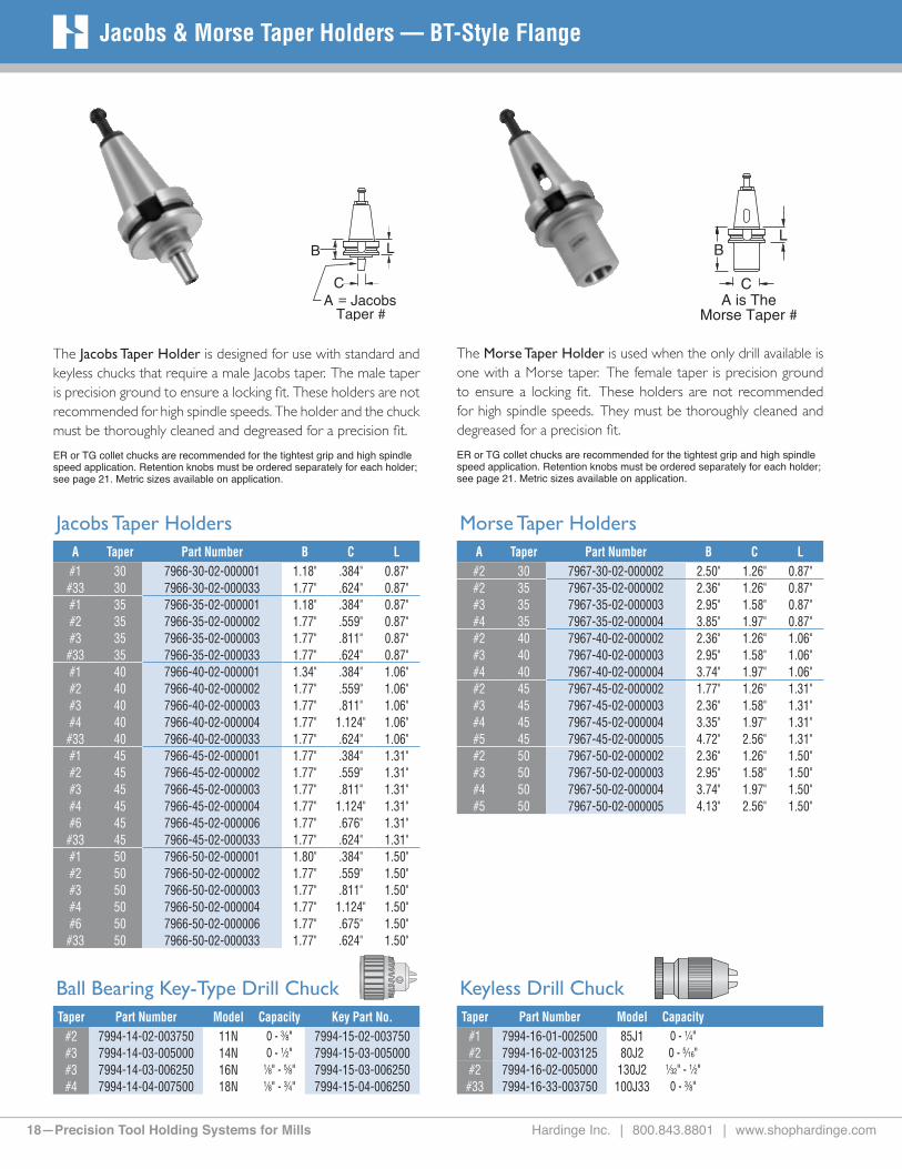
Ball Bearing Key-Type Drill ChuckTaper Part Number Model Capacity Key Part No.
#2 7994-14-02-003750 11N 0 - 3⁄8" 7994-15-02-003750#3 7994-14-03-005000 14N 0 - 1⁄2" 7994-15-03-005000#3 7994-14-03-006250 16N 1⁄8" - 5⁄8" 7994-15-03-006250#4 7994-14-04-007500 18N 1⁄8" - 3⁄4" 7994-15-04-006250
Jacobs & Morse Taper Holders — BT-Style Flange
The Jacobs Taper Holder is designed for use with standard and keyless chucks that require a male Jacobs taper. The male taper is precision ground to ensure a locking fit. These holders are not recommended for high spindle speeds. The holder and the chuck must be thoroughly cleaned and degreased for a precision fit.
ER or TG collet chucks are recommended for the tightest grip and high spindle speed application. Retention knobs must be ordered separately for each holder; see page 21. Metric sizes available on application.
The Morse Taper Holder is used when the only drill available is one with a Morse taper. The female taper is precision ground to ensure a locking fit. These holders are not recommended for high spindle speeds. They must be thoroughly cleaned and degreased for a precision fit.
ER or TG collet chucks are recommended for the tightest grip and high spindle speed application. Retention knobs must be ordered separately for each holder; see page 21. Metric sizes available on application.
Jacobs Taper HoldersA Taper Part Number B C L#1 30 7966-30-02-000001 1.18" .384" 0.87"
#33 30 7966-30-02-000033 1.77" .624" 0.87"#1 35 7966-35-02-000001 1.18" .384" 0.87"#2 35 7966-35-02-000002 1.77" .559" 0.87"#3 35 7966-35-02-000003 1.77" .811" 0.87"
#33 35 7966-35-02-000033 1.77" .624" 0.87"#1 40 7966-40-02-000001 1.34" .384" 1.06"#2 40 7966-40-02-000002 1.77" .559" 1.06"#3 40 7966-40-02-000003 1.77" .811" 1.06"#4 40 7966-40-02-000004 1.77" 1.124" 1.06"
#33 40 7966-40-02-000033 1.77" .624" 1.06"#1 45 7966-45-02-000001 1.77" .384" 1.31"#2 45 7966-45-02-000002 1.77" .559" 1.31"#3 45 7966-45-02-000003 1.77" .811" 1.31"#4 45 7966-45-02-000004 1.77" 1.124" 1.31"#6 45 7966-45-02-000006 1.77" .676" 1.31"
#33 45 7966-45-02-000033 1.77" .624" 1.31"#1 50 7966-50-02-000001 1.80" .384" 1.50"#2 50 7966-50-02-000002 1.77" .559" 1.50"#3 50 7966-50-02-000003 1.77" .811" 1.50"#4 50 7966-50-02-000004 1.77" 1.124" 1.50"#6 50 7966-50-02-000006 1.77" .675" 1.50"
#33 50 7966-50-02-000033 1.77" .624" 1.50"
Morse Taper HoldersA Taper Part Number B C L#2 30 7967-30-02-000002 2.50" 1.26" 0.87"#2 35 7967-35-02-000002 2.36" 1.26" 0.87"#3 35 7967-35-02-000003 2.95" 1.58" 0.87"#4 35 7967-35-02-000004 3.85" 1.97" 0.87"#2 40 7967-40-02-000002 2.36" 1.26" 1.06"#3 40 7967-40-02-000003 2.95" 1.58" 1.06"#4 40 7967-40-02-000004 3.74" 1.97" 1.06"#2 45 7967-45-02-000002 1.77" 1.26" 1.31"#3 45 7967-45-02-000003 2.36" 1.58" 1.31"#4 45 7967-45-02-000004 3.35" 1.97" 1.31"#5 45 7967-45-02-000005 4.72" 2.56" 1.31"#2 50 7967-50-02-000002 2.36" 1.26" 1.50"#3 50 7967-50-02-000003 2.95" 1.58" 1.50"#4 50 7967-50-02-000004 3.74" 1.97" 1.50"#5 50 7967-50-02-000005 4.13" 2.56" 1.50"
Keyless Drill ChuckTaper Part Number Model Capacity
#1 7994-16-01-002500 85J1 0 - 1⁄4"#2 7994-16-02-003125 80J2 0 - 5⁄16"#2 7994-16-02-005000 130J2 1⁄32" - 1⁄2"#33 7994-16-33-003750 100J33 0 - 3⁄8"

Hardinge Inc. | 800.843.8801 | www.shophardinge.com Precision Tool Holding Systems for Mills—19
www.Shop HARDINGE.comSemi-Flush Slitting & Stub Arbor Holders — BT-Style Flange
The Semi-Flush Slitting Saw Holder is designed for slitting saws up to 5⁄16" thick. The semi-flush cap allows the cutter to get into tight areas not accessible with stub arbor holders. Spacers are not required when changing saw widths. The pilot diameter is preci-sion ground concentric to the shank with the locating shoulder perpendicular to the centerline within .0002".
Retention knobs must be ordered separately for each holder; see page 21. See pages 6 and 7 for balance options.
The pilot diameter and thread on the Stub Arbor Holder is precision ground concentric to the shank. The diameter mates precisely to the cutter ID and is keyed to provide a positive drive. The locating shoulder is guaranteed to be perpendicular to the centerline within .0002". Included with each arbor is a heavy-duty locking nut, 1⁄4", 3⁄8" and 3⁄4" spacers.
Retention knobs must be ordered separately for each holder; see page 21.See pages 6 and 7 for balance options. Holders for metric tools are available on application.
Semi-Flush Slitting Saw HoldersTaper Part Number Saw ID B C L
40 7957-40-00-010000 1.00" 4.00" 1.50" 1.06"40 7957-40-00-012500 1.25" 4.00" 2.00" 1.06"
Cap and Drive KeysItem Part Number
Cap for 1" 7991-08-00-010000 Drive Key For 1" 7993-08-09-010000 Cap for 11⁄4" 7991-08-00-012500 Drive Key for 11⁄4" 7993-08-09-012500
Stub Arbor HoldersTaper Part No. Saw ID B C D L
40 7958-40-02-010000 1.00" 4.00" 1.56" 6.25" 1.06"40 7958-40-02-012500 1.25" 4.00" 1.87" 6.50" 1.06"45 7958-45-02-010000 1.00" 4.00" 1.56" 6.25" 1.31"45 7958-45-02-012500 1.25" 4.00" 1.87" 6.50" 1.31"50 7958-50-02-010000 1.00" 4.00" 1.56" 6.25" 1.50"50 7958-50-03-010000 1.00" 6.00" 1.56" 8.25" 1.50"50 7958-50-02-012500 1.25" 4.00" 1.87" 6.50" 1.50"50 7958-50-03-012500 1.25" 6.00" 1.87" 8.50" 1.50"
AccessoriesItem Part Number
Nut for 1" 7990-09-40-010000 Key For 1" 7993-09-09-010000 1⁄4" Spacer For 1" 7993-09-42-010000 3⁄8" Spacer For 1" 7993-09-43-010000 3⁄4" Spacer For 1" 7993-09-47-010000 Nut For 11⁄4" 7990-09-40-012500 Key For 11⁄4" 7993-09-09-012500 1⁄4" Spacer For 11⁄4" 7993-09-42-012500 3⁄8" Spacer For 11⁄4" 7993-09-43-012500 3⁄4" Spacer For 11⁄4" 7993-09-47-012500

20—Precision Tool Holding Systems for Mills Hardinge Inc. | 800.843.8801 | www.shophardinge.com
Boring Head & Blank Holders — BT-Flange
Thread
When special applications arise and you need to make your own holder, we suggest you start with our Blank Holders. They are made from 8620 alloy steel with the shank and flange case hardened and precision ground. We have left the head softer for easier machining. We offer a standard and short version to better meet your needs.
Retention knobs must be ordered separately for each holder; see page 21.
Hardinge Boring Head Holders will take the most popular adjust-able boring heads – Erickson #37 and #50 heads, SPI, Yuasa and Criterion heads. When ordering, make certain that you order the holder for your specific boring head.
Retention knobs must be ordered separately for each holder; see page 21.
Standard
Short
Boring Head HoldersTaper Part Number Thread L Boring Heads
30 7968-30-00-006250 5⁄8"-18 .87" Erickson #37 & #5030 7969-30-00-008750 7⁄8"-20 .87" SPI, Yuasa & Criterion35 7968-35-00-006250 5⁄8"-18 .87" Erickson #37 & #5035 7969-35-00-008750 7⁄8"-20 .87" SPI, Yuasa & Criterion40 7968-40-00-006250 5⁄8"-18 1.06" Erickson #37 & #5040 7969-40-00-008750 7⁄8"-20 1.06" SPI, Yuasa & Criterion40 7969-40-00-015000 11⁄2"-18 1.06" SPI, Yuasa & Criterion45 7968-45-00-006250 5⁄8"-18 1.06" Erickson #37 & #5045 7969-45-00-008750 7⁄8"-20 1.06" SPI, Yuasa & Criterion45 7969-45-00-015000 11⁄2"-18 1.06" SPI, Yuasa & Criterion50 7968-50-00-006250 5⁄8"-18 1.06" Erickson #37 & #5050 7969-50-00-008750 7⁄8"-20 1.06" SPI, Yuasa & Criterion50 7969-50-00-015000 11⁄2"-18 1.06" SPI, Yuasa & Criterion
Blank HoldersTaper Part Number C D L
30 7970-30-01-000000 13⁄4" 6" short .87"35 7970-35-01-000000 23⁄8" 6" short .87"35 7970-35-02-000000 23⁄8" 11" standard .87"40 7970-40-01-000000 21⁄2" 6" short 1.06"40 7970-40-02-000000 21⁄2" 11" standard 1.06"45 7970-45-01-000000 31⁄4" 6" short 1.31"45 7970-45-02-000000 31⁄4" 11" standard 1.31"50 7970-50-01-000000 37⁄8" 6" short 1.50"50 7970-50-02-000000 37⁄8" 11" standard 1.50"
C
D
L

Hardinge Inc. | 800.843.8801 | www.shophardinge.com Precision Tool Holding Systems for Mills—21
www.Shop HARDINGE.comRetention Knobs — BT-Style Flange
If the specifications for your retention knob do not appear in our listing, please fill out this Retention Knob Request Form and give us a call.
A inch/mm _________________
B inch/mm _________________
C inch/mm _________________
D inch/mm _________________
Angle degrees _______________
Thread ____________________
Toolholder Shank Style
__________________________
Machine Make ______________
Machine Model ______________
Coolant Hole–Yes/No _________
Hole Diameter ______________
O-Ring–Yes/No ______________
(send print for position) Caution: Our retention knobs are built to the machine tool builder’s specifications. Using retention knobs which do not conform to these specifications can cause damage to your tooling and/or machine tool.
Angle
Angle
Our retention knobs are manufactured to the industrial standards indicated in the charts. The knobs are made from tool steel that was heat treated to ensure durability and excellent performance. In addition to U.S. ANSI and MAS Styles, retention knobs are also available for other domestic and imported machining centers.
Due to the many different retention knobs used by machining center manu-facturers, you may not find your knob in our catalog. We stock hundreds of knobs not listed. Please fill out the re-tention knob request form. If it is not a stock item, we will manufacture it to your machine tool builder’s specifications.
Angle
* Wrench flats are on the knob end“C" at the end of the Taper and Flange number designates a Coolant hole
MAS Style BT-Flange Retention KnobsTaper and
FlangePart Number A B C Angle Thread
Size
Max. Torque (f t-lb)
BT30 7985-30-20-000001 0.43" 0.27" 0.90" 45 M12-1.75 40BT30 7985-30-20-000002 0.43" 0.27" 0.90" 60 M12-1.75 40BT35 7985-35-20-000001 0.51" 0.33" 1.10" 45 M12-1.75 40BT35 7985-35-20-000002 0.51" 0.33" 1.10" 60 M12-1.75 40BT40 7985-40-20-000001 0.59" 0.39" 1.38" 45 M16-2.0 85
BT40C 7985-40-21-000001 0.59" 0.39" 1.38" 45 M16-2.0 85BT40 7985-40-20-000002 0.59" 0.39" 1.38" 60 M16-2.0 85
BT40C 7985-40-21-000002 0.59" 0.39"" 1.38" 60 M16-2.0 85BT40 7985-40-20-000003 0.59" 0.39" 1.38" 90 M16-2.0 85BT45 7985-45-20-000001 0.75" 0.55" 1.57" 45 M20-2.5 100BT45 7985-45-20-000002 0.75" 0.55" 1.57" 60 M20-2.5 100BT45 7985-45-20-000003 0.75" 0.55" 1.57" 90 M20-2.5 100BT50 7985-50-20-000001 0.91" 0.67" 1.77" 45 M24-3.0 110
BT50C 7985-50-21-000001 0.91" 0.67" 1.77" 45 M24-3.0 110BT50 7985-50-20-000002 0.91" 0.67" 1.77" 60 M24-3.0 110BT50 7985-50-20-000003 0.91" 0.67" 1.77" 90 M24-3.0 110
BT50C 7985-50-21-000002 0.91" 0.67" 1.77" 90 M24-3.0 110
U.S. ANSI BT-Flange Retention Knobs with Coolant HoleTaper and
FlangePart Number A B C Angle Thread
Size
Max. Torque (f t-lb)
BT40C 7985-40-11-000001 0.74" 0.49" 0.64" 45 M16-2.0 85BT40C 7985-40-11-000002 0.74" 0.49" 0.75" 45 M16-2.0 85BT45C 7985-45-11-000001 0.94" 0.61" 0.82" 45 M20-2.5 100BT50C 7985-50-11-000001 1.14" 0.83" 1.00" 45 M24-3.0 110
Other Style BT-Flange Retention KnobsTaper and
FlangePart Number A B C Angle Thread
Size
Max. Torque (f t-lb)
BT30 7985-30-30-000001 0.47" 0.31" 0.94" .16 R* M12-1.75 40BT30C 7985-30-31-000001 0.47" 0.31" 0.92" 75 M12-1.75 40BT35 7985-35-30-000001 0.54" 0.35" 1.10" 60 M12-1.75 40BT35 7985-35-30-000002 0.55" 0.31" 0.91" 90 M12-1.75 40BT40 7985-40-30-000001 0.75" 0.55" 1.13" 75 M16-2.0 85
BT40C 7985-40-31-000001 0.75" 0.55" 1.14" 75 M16-2.0 85BT40 7985-40-30-000002 0.59" 0.39" 1.09" 90 M16-2.0 85BT40 7985-40-30-000003 0.59" 0.39" 0.98" 90 M16-2.0 85
BT40H 7985-40-32-000001 0.75" 0.55" 1.14" 75 M16-2.0 85BT45 7985-45-30-000001 0.91" 0.67" 1.18" 75 M20-2.5 100
See page 37 for Bridgeport machine knob compatibility.

22—Precision Tool Holding Systems for Mills Hardinge Inc. | 800.843.8801 | www.shophardinge.com
S & R SHANK
Style Taper Part No. B C D L
ER20 40 7933-40-50 6.00" 1.26" 3.5" 1.38"ER20 50 7933-50-50 6.00" 1.26" 3.5" 1.38"ER20 50 7933-50-51 8.00" 1.26" 3.5" 1.38"ER32 50 7935-50-50 6.00" 1.88" 4.0" 1.38"ER32 50 7935-50-51 8.00" 1.88" 4.0" 1.38"
STANDARD EXTENDED EXTRA EXTENDED
Style Taper Part No. B C D L Part No. B C D L Part No. B C D L
ER16 45 7932-45-02 3.88" 1.08" 3.0" 1.38"ER20 45 7933-45-02 4.00" 1.26" 3.5" 1.38"ER32 45 7935-45-02 4.00" 1.88" 4.0" 1.38"ER16 50 7932-50-02 4.88" 1.08" 3.0" 1.38" 7932-50-03 6.88" 1.08" 3.0" 1.38"ER20 50 7933-50-02 4.00" 1.26" 3.5" 1.38" 7933-50-03 6.00" 1.26" 3.5" 1.38" 7933-50-04 8.00" 1.26" 3.5" 1.38"ER25 50 7934-50-02 4.00" 1.65" 3.5" 1.38" 7934-50-03 6.00" 1.65" 3.5" 1.38"ER32 50 7935-50-02 4.00" 1.88" 4.0" 1.38" 7935-50-03 6.00" 1.88" 4.0" 1.38" 7935-50-04 8.00" 1.88" 4.0" 1.38"
Precision ER Holders – CAT-V Flange
STUB STANDARD EXTENDED
Style Taper Part No. B C D L Part No. B C D L Part No. B C D L
ER11 30ER16 30 7932-30-02 3.00" 1.08" 2.7" 1.38"ER20 30 7933-30-02 3.00" 1.26" 3.0" 1.38"ER32 30 7935-30-02 3.00" 1.88" 2.5" 1.38"ER11 40 7931-40-02 3.00" .63" 1.6" 1.38"ER16 40 7932-40-02 2.88" 1.08" 3.0" 1.38" 7932-40-03 4.88" 1.08" 3.0" 1.38"ER20 40 7933-40-01 2.55" 1.26" 2.9" 1.38" 7933-40-02 4.00" 1.26" 3.5" 1.38" 7933-40-03 6.00" 1.26" 3.5" 1.38"
ER20X 40 7933-40-04 8.00" 1.26" 3.5" 1.38"ER25 40 7934-40-01 2.50" 1.65" 3.0" 1.38" 7934-40-02 4.00" 1.65" 3.5" 1.38" 7934-40-03 6.00" 1.65" 3.5" 1.38"ER32 40 7935-40-01 2.70" 1.88" 3.3" 1.38" 7935-40-02 4.00" 1.88" 4.0" 1.38" 7935-40-03 6.00" 1.88" 4.0" 1.38"
Precision ER Collet Chucks — CAT-V Flange
ER Collet Holders are available from ER11 to ER32 Styles (.019" to .787" diameters). The flush, precision nosepiece grips the tool close to the cutting edge for better accuracy. The shank taper accuracy for the holders is AT-3 or better. They are made to precision specifications. Each style is concentric to the centerline within .0002". ER holders give you the flexibility to mill, drill, ream, bore and tap.Retention knobs must be ordered separately for each holder; see pages 35 and 36. High-pressure coolant seals; see page 47. Balance options; see pages 6 and 7.
S&R (Strong and Rugged)These extra strong and rugged long tool holders steady the tool for smoother, and faster cutting. Tools last longer due to the added mass of the holder that decreases vibration. Accepts double-ended end mills.
Note: Suffix X indicates Extra-Extended Holder
ER16 ER32ER25ER20ER11 S & R

Hardinge Inc. | 800.843.8801 | www.shophardinge.com Precision Tool Holding Systems for Mills—23
www.Shop HARDINGE.com
C C C C
UrethaneSeal
ER Collet Chuck Accessories — CAT-V Flange
Why shouldn’t I use end mills with Weldon flats in collet-style holders? Non-symmetrical tools should not be used in a collet-style holder. The Weldon flat makes the end mill unbalanced (non-symmetrical) resulting in poor finishes and possible spindle damage.FAQ
Collets for ER Holders — see pages 43-44 for additional collet informationMetric Collets Fractional Collets Tap Collets – Split
Style Base Part No. Range Range Inches Base Part No. Range Base Part No. Range
ER11 1911-00-17- 1 mm to 07 mm .019" to .275" 1911-00-19- 1⁄16" to 1⁄4" — —ER16 1913-00-17- 1 mm to 10 mm .019" to .393" 1913-00-19- 1⁄16" to 13⁄32" 1913-00-18- #0 to 1⁄4" ER20 1915-00-17- 2 mm to 13 mm .039" to .511" 1915-00-19- 1⁄16" to 1⁄2" 1915-00-18- #8 to 1⁄2" ER25 2095-00-17- 2 mm to 16 mm .039" to .629" 2095-00-19- 1⁄16" to 5⁄8" 2095-00-18- #8 to 5⁄8" ER32 1917-00-17- 3 mm to 20 mm .078" to .787" 1917-00-19- 3⁄32" to 3⁄4" 1917-00-18- #8 to 13⁄16"
Stop Screws and Clips for ER Holders
Style
ER Standard Part No.
ER Standard Coolant 400psi
Part No.Thread Extractor Clips
Package of 10
ER11 — — — —ER16 7990-01-16-000004 7990-01-16-000006 7⁄16" - 20 7993-01-16-000007ER20 7990-01-20-000004 7990-01-20-000006 M14 - 1.5 7993-01-20-000007ER25 7990-01-25-000004 7990-01-25-000006 M18 - 1.5 7993-01-25-000007ER32 7990-01-32-000004 7990-01-32-000006 M22 - 1.5 7993-01-32-000007
ERQC Collets are shown on page 46.
Nosepiece Caps and Wrenches for ER Collet Chuck Holders
Style
Taper
C Dia.
Standard Part No.
Ball Bearing Part No.
Wrench for Std. & Ball Bearing
Part No.
Fine Tune Part No.
U-Balance Part No.
Wrench for Fine & U-Bal. Part No.
ER11 All .63" 7991-01-11-000001 — 7992-01-11-000003 — — —ER16 All 1.08" 7991-01-16-000001 — 7992-01-16-000003 7991-01-16-000009 7991-01-16-000010 7992-01-16-000009ER20 All 1.26" 7991-01-20-000001 7991-01-20-000008 7992-01-20-000003 7991-01-20-000009 7991-01-20-000010 7992-01-20-000009ER25 All 1.65" 7991-01-25-000001 7991-01-25-000008 7992-01-25-000003 7991-01-25-000009 7991-01-25-000010 7992-01-25-000009ER32 All 1.88" 7991-01-32-000001 7991-01-32-000008 7992-01-32-000003 7991-01-32-000009 7991-01-32-000010 7992-01-32-000009
Quick-Change Floating Solid Tap Collets Style Base Part No. Range ERQC16 2143-00-18- #0 - #10 ERQC20 2145-00-18- #0 - 1⁄4" ERQC25 2147-00-18- #0 - 1⁄2" ERQC32 2149-00-18- #0 - 9⁄16"
Floating Solid Tap Collets Style Base Part No. Range ERTC16 1921-00-18- #0 - #10 ERTC20 1923-00-18- #0 - 1⁄4" ERTC25 2097-00-18- #0 - 1⁄2" ERQC32 2099-00-18- #8 - 5⁄8"
ERTC Collets are shown on page 45.

24—Precision Tool Holding Systems for Mills Hardinge Inc. | 800.843.8801 | www.shophardinge.com
Precision TG Collet Chucks — CAT-V Flange
Precision TG Holders – CAT-V Flange
STANDARD/STUB EXTENDED EXTRA EXTENDED
Style Taper Part No. B C D L Part No. B C D L Part No. B C D L
TG100 30 7929-30-02 4.34" 2.50" 2.0" 1.38"TG100 40 7929-40-02 3.25" 2.50" 2.9" 1.38" 7929-40-03 4.50" 2.50" 3.9" 1.38" 7929-40-04 6.25" 2.50" 5.0" 1.38"TG150 40 7930-40-02 4.88" 3.50" 3.8" 1.38"TG100 45 7929-45-02 3.75" 2.50" 4.3" 1.38" 7929-45-03 6.00" 2.50" 5.0" 1.38" 7929-45-04 7.75" 2.50" 5.0" 1.38"TG150 45 7930-45-02 4.00" 3.50" 4.4" 1.38" 7930-45-03* 6.00" 3.50" 5.0" 1.38" 7930-45-04* 8.00" 3.50" 5.0" 1.38"
TG100S 50 7929-50-01 2.75" 2.50" 3.7" 1.37"TG100 50 7929-50-02 3.25" 2.50" 4.2" 1.38" 7929-50-03 5.50" 2.50" 5.0" 1.38" 7929-50-04 7.25" 2.50" 5.0" 1.38"TG150 50 7930-50-02 3.50" 3.50" 4.5" 1.38" 7930-50-03* 5.50" 3.50" 5.0" 1.38" 7930-50-04* 7.50" 3.50" 5.0" 1.38"
Note: D - Depth of Stop Screw, S - Stub Holder, * Requires Stop Screw
TG Collet Holders are available for the TG100 and TG150 (.093" to 1.5" diameter) collets. The TG Holders have a flush nosepiece design incorporat-ing a rotating ball assembly which produces a radial float. This, in turn, forces the collet to self-center for maximum grip, precision and extended tool life.
Retention knobs are ordered separately; see pages 35 and 36. “Cool Stop" high-pressure coolant seals available on page 47. For balance options; see pages 6 and 7. Maximum recommended torque is 60 ft-lb – DO NOT OVER-TORQUE
Stop Screws for TG Holders
Style
ThreadTG Stop Screw
Standard Part No.TG Stop Screw Coolant
400 psi Part No.TG100 11⁄8" x 16 7990-02-10-000004 7990-02-10-000006TG150 13⁄8" x 12 7990-02-15-000004 7990-02-15-000006TG150 15⁄8" x 12 7990-02-15-000014 7990-02-15-000016
Nosepiece and Wrench for TG Holders
Style
TaperC
DiameterTG Nosepiece
Part No.WrenchPart No.
TG100 All 2.50" 7991-02-10-000014 7992-02-10-000003TG150 All 3.50" 7991-02-15-000015 7992-02-15-000003
UrethaneSeal
TG collets have a shallow single-angle to ensure precise concentricity between the collet, the holder and the tool. The nosepiece associated with the TG holder incorporates a rotating ball assembly with a radial float. The accuracy of this system is unsurpassed by any other. Coolant seals are shown on page 47.
Standard TG Collets
StyleInch
Part No.Range
1/64" IncrementsMetric
Part No. Range
TG100 1905-00-19- 3⁄32" to 1" 1905-00-17- 6.0mm to 25.5mmTG150 1909-00-19- 1⁄2" to 11⁄2" 1909-00-17- 12.mm to 38.0mm
See the next page for the full range of TG Collets and part numbers.
TG Collet RacksTG100 TG150
Part No. 0946-10-00-000035 0946-15-00-000025Capacity 35 TG100 Collets 25 TG150 Collets
TG100
TG150

Hardinge Inc. | 800.843.8801 | www.shophardinge.com Precision Tool Holding Systems for Mills—25
www.Shop HARDINGE.comPrecision TG Collets
TG Collets — Inch Inch TG100 Part Number Inch TG150 Part Number3/32" 1905-00-19-000937 1⁄2" 1909-00-19-0050007/64" 1905-00-19-001093 33⁄64" 1909-00-19-0051561/8" 1905-00-19-001250 17⁄32" 1909-00-19-0053129/64" 1905-00-19-001406 35⁄64" 1909-00-19-0054685/32" 1905-00-19-001562 9⁄16" 1909-00-19-005625
11/64" 1905-00-19-001718 37⁄64" 1909-00-19-0057813/16" 1905-00-19-001875 19⁄32" 1909-00-19-005937
13/64" 1905-00-19-002031 39⁄64" 1909-00-19-0060937/32" 1905-00-19-002187 5⁄8" 1909-00-19-006250
15/64" 1905-00-19-002343 41⁄64" 1909-00-19-0064061/4" 1905-00-19-002500 21⁄32" 1909-00-19-006562
17/64" 1905-00-19-002656 43⁄64" 1909-00-19-0067189/32" 1905-00-19-002812 11⁄16" 1909-00-19-006875
19/64" 1905-00-19-002968 45⁄64" 1909-00-19-0070315/16" 1905-00-19-003125 23⁄32" 1909-00-19-007187
21/64" 1905-00-19-003281 47⁄64" 1909-00-19-00734311/32" 1905-00-19-003437 3⁄4" 1909-00-19-00750023/64" 1905-00-19-003593 49⁄64" 1909-00-19-007656
3/8" 1905-00-19-003750 25⁄32" 1909-00-19-00781225⁄64" 1905-00-19-003906 51⁄64" 1909-00-19-00796813⁄32" 1905-00-19-004062 13⁄16" 1909-00-19-00812527⁄64" 1905-00-19-004218 53⁄64" 1909-00-19-0082817⁄16" 1905-00-19-004375 27⁄32" 1909-00-19-00843729⁄64" 1905-00-19-004531 55⁄64" 1909-00-19-00859315⁄32" 1905-00-19-004687 7⁄8" 1909-00-19-00875031⁄64" 1905-00-19-004843 57⁄64" 1909-00-19-0089061⁄2" 1905-00-19-005000 29⁄32" 1909-00-19-009062
33⁄64" 1905-00-19-005156 59⁄64" 1909-00-19-00921817⁄32" 1905-00-19-005312 15⁄16" 1909-00-19-00937535⁄64" 1905-00-19-005468 61⁄64" 1909-00-19-009531 9⁄16" 1905-00-19-005625 31⁄32" 1909-00-19-00968737⁄64" 1905-00-19-005781 63⁄64" 1909-00-19-00984319⁄32" 1905-00-19-005937 1" 1909-00-19-01000039⁄64" 1905-00-19-006093 11⁄64" 1909-00-19-0101565⁄8" 1905-00-19-006250 11⁄32" 1909-00-19-010312
41⁄64" 1905-00-19-006406 13⁄64" 1909-00-19-01046821⁄32" 1905-00-19-006562 11⁄16" 1909-00-19-01062543⁄64" 1905-00-19-006718 15⁄64" 1909-00-19-01078111⁄16" 1905-00-19-006875 13⁄32" 1909-00-19-01093745⁄64" 1905-00-19-007031 17⁄64" 1909-00-19-01109323⁄32" 1905-00-19-007187 11⁄8" 1909-00-19-01125047⁄64" 1905-00-19-007343 19⁄64" 1909-00-19-0114063⁄4" 1905-00-19-007500 13⁄16" 1909-00-19-011562
49⁄64" 1905-00-19-007656 111⁄64" 1909-00-19-01171825⁄32" 1905-00-19-007812 13⁄16" 1909-00-19-01187551⁄64" 1905-00-19-007968 113⁄64" 1909-00-19-01203113⁄16" 1905-00-19-008125 17⁄32" 1909-00-19-01218753⁄64" 1905-00-19-008281 115⁄64" 1909-00-19-01234327⁄32" 1905-00-19-008437 11⁄4" 1909-00-19-01250055⁄64" 1905-00-19-008593 117⁄64" 1909-00-19-0126567⁄8" 1905-00-19-008750 19⁄32" 1909-00-19-012812
57⁄64" 1905-00-19-008906 119⁄64" 1909-00-19-01296829⁄32" 1905-00-19-009062 15⁄16" 1909-00-19-01312559⁄64" 1905-00-19-009218 121⁄64" 1909-00-19-01328115⁄16" 1905-00-19-009375 111⁄32" 1909-00-19-01343761⁄64" 1905-00-19-009531 123⁄64" 1909-00-19-01359331⁄32" 1905-00-19-009687 13⁄8" 1909-00-19-01375063⁄64" 1905-00-19-009843 125⁄64" 1909-00-19-0139061" 1905-00-19-010000 113⁄32" 1909-00-19-014062
127⁄64" 1909-00-19-01421817⁄16" 1909-00-19-014375129⁄64" 1909-00-19-014531115⁄32" 1909-00-19-014687131⁄64" 1909-00-19-01484311⁄2" 1909-00-19-015000
TG Collet SetsPart Numbers Qty. Range & Increment
TG100 0932-00-19-000059 59 3⁄32" to 1" (1⁄64" Incr.)TG100 0932-00-19-000041 41 3⁄8" to 1" (1⁄64" Incr.)TG100 0932-00-19-000030 30 3⁄32" to 1" (1⁄32" Incr.)TG100 0932-00-19-000021 21 3⁄8" to 1" (1⁄32" Incr.)TG150 0934-00-19-000065 65 1⁄2" to 11⁄2" (1⁄64" Incr.)TG150 0934-00-19-000033 33 1⁄2" to 11⁄2" (1⁄32" Incr.)TG150 0934-00-19-000017 17 1⁄2" to 11⁄2" (1⁄16" Incr.)
TG Collets — Metricmm TG100 Part Number TG150 Part Number6.0 1905-00-17-060000 12.0 1909-00-17-1200006.5 1905-00-17-065000 12.5 1909-00-17-1250007.0 1905-00-17-070000 13.0 1909-00-17-1300007.5 1905-00-17-075000 13.5 1909-00-17-1350008.0 1905-00-17-080000 14.0 1909-00-17-1400008.5 1905-00-17-085000 14.5 1909-00-17-1450009.0 1905-00-17-090000 15.0 1909-00-17-1500009.5 1905-00-17-095000 15.5 1909-00-17-15500010.0 1905-00-17-100000 16.0 1909-00-17-16000010.5 1905-00-17-105000 16.5 1909-00-17-16500011.0 1905-00-17-110000 17.0 1909-00-17-17000011.5 1905-00-17-115000 17.5 1909-00-17-17500012.0 1905-00-17-120000 18.0 1909-00-17-18000012.5 1905-00-17-125000 18.5 1909-00-17-18500013.0 1905-00-17-130000 19.0 1909-00-17-19000013.5 1905-00-17-135000 19.5 1909-00-17-19500014.0 1905-00-17-140000 20.0 1909-00-17-20000014.5 1905-00-17-145000 20.5 1909-00-17-205000 15.0 1905-00-17-150000 21.0 1909-00-17-21000015.5 1905-00-17-155000 21.5 1909-00-17-21500016.0 1905-00-17-160000 22.0 1909-00-17-22000016.5 1905-00-17-165000 22.5 1909-00-17-22500017.0 1905-00-17-170000 23.0 1909-00-17-23000017.5 1905-00-17-175000 23.5 1909-00-17-23500018.0 1905-00-17-180000 24.0 1909-00-17-24000018.5 1905-00-17-185000 24.5 1909-00-17-24500019.0 1905-00-17-190000 25.0 1909-00-17-25000019.5 1905-00-17-195000 25.5 1909-00-17-25500020.0 1905-00-17-200000 26.0 1909-00-17-26000020.5 1905-00-17-205000 26.5 1909-00-17-26500021.0 1905-00-17-210000 27.0 1909-00-17-27000021.5 1905-00-17-215000 27.5 1909-00-17-27500022.0 1905-00-17-220000 28.0 1909-00-17-28000022.5 1905-00-17-225000 28.5 1909-00-17-28500023.0 1905-00-17-230000 29.0 1909-00-17-29000023.5 1905-00-17-235000 29.5 1909-00-17-29500024.0 1905-00-17-240000 30.0 1909-00-17-30000024.5 1905-00-17-245000 30.5 1909-00-17-30500025.0 1905-00-17-250000 31.0 1909-00-17-31000025.5 1905-00-17-255000 31.5 1909-00-17-315000
32.0 1909-00-17-32000032.5 1909-00-17-32500033.0 1909-00-17-33000033.5 1909-00-17-33500034.0 1909-00-17-34000034.5 1909-00-17-34500035.0 1909-00-17-35000035.5 1909-00-17-35500036.0 1909-00-17-36000036.5 1909-00-17-36500037.0 1909-00-17-37000037.5 1909-00-17-37500038.0 1909-00-17-380000

26—Precision Tool Holding Systems for Mills Hardinge Inc. | 800.843.8801 | www.shophardinge.com
40-TAPER S & R SHANK
Style Taper Part No. B C D L
0.375" 40 7921-40-50-003750 6.00" 1.00" 7.6" 1.38"0.500" 40 7921-40-50-005000 6.00" 1.25" 7.3" 1.38"
40-TAPER METRIC STANDARD
50-TAPER METRIC STANDARD
A Taper Part No. B C D L A Taper Part No. B C D L
6 mm 40 7922-40-02-060000 2.50" 0.97" 2.6" 1.38" 6 mm 50 7922-50-02-060000 2.50" 0.97" 3.4" 1.38"8 mm 40 7922-40-02-080000 2.50" 1.09" 2.5" 1.38" 8 mm 50 7922-50-02-080000 2.50" 1.09" 3.4" 1.38"10 mm 40 7922-40-02-100000 2.63" 1.37" 2.7" 1.38" 10 mm 50 7922-50-02-100000 2.63" 1.37" 3.5" 1.38"12 mm 40 7922-40-02-120000 2.63" 1.64" 2.7" 1.38" 12 mm 50 7922-50-02-120000 2.63" 1.64" 3.5" 1.38"14 mm 40 7922-40-02-140000 3.75" 1.81" 3.8" 1.38" 14 mm 50 7922-50-02-140000 3.75" 1.81" 4.6" 1.38"16 mm 40 7922-40-02-160000 3.75" 1.88" 2.2" 1.38" 16 mm 50 7922-50-02-160000 3.75" 1.88" 4.6" 1.38"18 mm 40 7922-40-02-180000 3.75" 1.96" 2.4" 1.38" 18 mm 50 7922-50-02-180000 3.75" 1.96" 4.6" 1.38"20 mm 40 7922-40-02-200000 3.75" 2.04" 2.4" 1.38" 20 mm 50 7922-50-02-200000 3.75" 2.04" 4.6" 1.38"
End Mill Holders 40-Taper and 50-Taper Metric – CAT-V Flange
40-TAPER STUB 40-TAPER STANDARD
40-TAPER EXTENDED
A Taper Part No. B C D L Part No. B C D L Part No. B C D L
0.125" 40 7921-40-02-001250 2.50" 0.69" 4.1" 1.38"0.187" 40 7921-40-02-001875 2.50" 0.69" 2.5" 1.38"0.250" 40 7921-40-02-002500 2.50" 0.78" 2.5" 1.38"0.312" 40 7921-40-02-003125 2.50" 0.88" 4.1" 1.38"0.375" 40 7921-40-02-003750 2.50" 1.00" 2.5" 1.38" 7921-40-03-003750 4.50" 1.00" 4.5" 1.38"0.437" 40 7921-40-02-004375 2.50" 1.13" 4.1" 1.38"0.500" 40 7921-40-01-005000 1.75" 1.25" 3.3" 1.38" 7921-40-02-005000 2.63" 1.25" 2.7" 1.38" 7921-40-03-005000 4.63" 1.25" 4.7" 1.38"0.562" 40 7921-40-02-005625 2.63" 1.38" 3.0" 1.38"0.625" 40 7921-40-01-006250 1.75" 1.50" 2.4" 1.38" 7921-40-02-006250 3.75" 1.50" 3.6" 1.38" 7921-40-03-006250 5.75" 1.50" 3.6" 1.38"0.750" 40 7921-40-01-007500 1.75" 1.75" 2.5" 1.38" 7921-40-02-007500 3.75" 1.75" 3.9" 1.38" 7921-40-03-007500 5.75" 1.75" 3.9" 1.38"0.875" 40 7921-40-02-008750 4.00" 1.88" 4.2" 1.38" 7921-40-03-008750 6.00" 1.88" 4.2" 1.38"1.000" 40 7921-40-01-010000 1.75" 1.75" 2.5" 1.38" 7921-40-02-010000 4.00" 2.00" 4.4" 1.38" 7921-40-03-010000 6.00" 2.00" 4.4" 1.38"1.250" 40 7921-40-01-012500 2.00" 2.25" 2.4" 1.38" 7921-40-02-012500 4.25" 2.50" 4.0" 1.38" 7921-40-03-012500 6.25" 2.50" 4.0" 1.38"1.500" 40 7921-40-02-015000 4.63" 2.50" 3.0" 1.38" 7921-40-03-015000 6.63" 2.50" 4.0" 1.38"
End Mill Holders — CAT-V Flange
End Mill Holders are offered in stub, standard, extended and S & R (strong & rug-ged) models. The fine pitch set screws match Weldon flats to firmly lock the end mill. All holders, except the stub holders from 1⁄8" up to 1" diameter, can accept single- or double-end tools. The stub holder will only accept single-end tools. Holders (except the stub) for end mills 1" and larger have two locking screws. The locking screws are aligned with the drive slot for your convenience. End mills without Weldon flats should not be used in these holders. Locking set screws are included.
Retention knobs must be ordered separately for each holder; see pages 35 and 36.
S&R (Strong and Rugged)These extra strong and rugged long tool holders steady the tool for smoother, and faster cutting. Tools last longer due to the added mass of the holder that decreases vibration. Accepts double-ended end mills.

Hardinge Inc. | 800.843.8801 | www.shophardinge.com Precision Tool Holding Systems for Mills—27
www.Shop HARDINGE.com
Replacement Locking Screws End MillDia. Size
Locking ScrewPart No.
Thread Size Length Torque(In-lb)
0.125" 7990-12-45-000008 8-32 .25" 180.188" 7990-12-45-000010 10-32 .25" 300.250" 7990-12-45-002500 1⁄4"-28 .25" 600.313" 7990-12-45-003125 5⁄16"-24 .25" 1200.375" 7990-12-45-003750 3⁄8"-24 .25" 2000.500" 7990-12-45-004375 7⁄16"-20 .36" 2200.625" 7990-12-45-005000 1⁄2"-20 .42" 5000.750" 7990-12-45-006250 5⁄8"-18 .49" 5600.875" 7990-12-45-006250 5⁄8"-18 .49" 5601.000" 7990-12-45-007500 3⁄4"-16 .45" 11501.250" 7990-12-45-007500 3⁄4"-16 .45" 11501.500" 7990-12-45-007500 3⁄4"-16 .45" 11502.000" 7990-12-45-010000 1"-14 .88" 15006 mm 7990-13-45-060000 M6 - 1.0 10 608 mm 7990-13-45-080000 M8 - 1.25 10 12010 mm 7990-13-45-100000 M10 - 1.5 12 18012 mm 7990-13-45-120000 M12 - 1.75 16 25014 mm 7990-13-45-120000 M12 - 1.75 16 25016 mm 7990-13-45-140000 M14 - 2.0 16 45018 mm 7990-13-45-140000 M14 - 2.0 16 45020 mm 7990-13-45-160000 M16 - 2.0 16 840
50-TAPER S&R HOLDER
A Taper Part No. B C D L
0.375" 50 7921-50-50-003750 6.00" 1.00" 8.4" 1.38"0.375" 50 7921-50-51-003750 8.00" 1.00" 10.4" 1.38"0.375" 50 7921-50-52-003750 10.00" 1.00" 12.4" 1.38"0.375" 50 7921-50-53-003750 12.00" 1.00" 14.4" 1.38"0.500" 50 7921-50-50-005000 6.00" 1.25" 8.4" 1.38"0.500" 50 7921-50-51-005000 8.00" 1.25" 10.4" 1.38"0.500" 50 7921-50-52-005000 10.00" 1.25" 12.4" 1.38"0.500" 50 7921-50-53-005000 12.00" 1.25" 14.4" 1.38"0.625" 50 7921-50-50-006250 6.00" 1.50" 8.4" 1.38"0.625" 50 7921-50-51-006250 8.00" 1.50" 10.4" 1.38"0.625" 50 7921-50-52-006250 10.00" 1.50" 12.4" 1.38"0.625" 50 7921-50-53-006250 12.00" 1.50" 3.6" 1.38"0.750" 50 7921-50-50-007500 6.00" 1.75" 8.4" 1.38"0.750" 50 7921-50-51-007500 8.00" 1.75" 10.4" 1.38"0.750" 50 7921-50-52-007500 10.00" 1.75" 12.4" 1.38"0.750" 50 7921-50-53-007500 12.00" 1.75" 3.9" 1.38"1.000" 50 7921-50-50-010000 6.00" 2.00" 4.4" 1.38"1.000" 50 7921-50-51-010000 8.00" 2.00" 4.4" 1.38"1.000" 50 7921-50-52-010000 10.00" 2.00" 4.4" 1.38"1.000" 50 7921-50-53-010000 12.00" 2.00" 4.4" 1.38"
End Mill Holders — CAT-V Flange
50-TAPER STANDARD
50-TAPER EXTENDED
50-TAPER EXTRA EXTENDED
A Taper Part No. B C D L Part No. B C D L Part No. B C D L
0.125" 50 7921-50-02-001250 2.50" 0.69" 4.9" 1.38"0.187" 50 7921-50-02-001875 2.50" 0.69" 3.4" 1.38"0.250" 50 7921-50-02-002500 2.50" 0.78" 3.4" 1.38"0.312" 50 7921-50-02-003125 2.50" 0.88" 4.9" 1.38"0.375" 50 7921-50-02-003750 2.50" 1.00" 3.4" 1.38" 7921-50-03-003750 4.50" 1.00" 5.4" 1.38" 7921-50-04-003750 6.50" 1.00" 5.4" 1.38"0.437" 50 7921-50-02-004375 2.63" 1.13" 5.0" 1.38"0.500" 50 7921-50-02-005000 2.63" 1.25" 3.5" 1.38" 7921-50-03-005000 4.63" 1.25" 5.5" 1.38" 7921-50-04-005000 6.63" 1.25" 5.5" 1.38"0.562" 50 7921-50-02-005625 2.63" 1.38" 5.0" 1.38"0.625" 50 7921-50-02-006250 3.75" 1.50" 4.6" 1.38" 7921-50-03-006250 5.75" 1.50" 6.6" 1.38" 7921-50-04-006250 7.75" 1.50" 6.6" 1.38"0.750" 50 7921-50-02-007500 3.75" 1.75" 4.6" 1.38" 7921-50-03-007500 5.75" 1.75" 6.6" 1.38" 7921-50-04-007500 7.75" 1.75" 8.6" 1.38"0.875" 50 7921-50-02-008750 3.75" 1.88" 4.2" 1.38" 7921-50-03-008750 5.75" 1.88" 6.6" 1.38" 7921-50-04-008750 7.75" 1.88" 4.2" 1.38"1.000" 50 7921-50-02-010000 4.00" 2.00" 4.4" 1.38" 7921-50-03-010000 6.00" 2.00" 4.4" 1.38" 7921-50-04-010000 8.00" 2.00" 4.4" 1.38"1.250" 50 7921-50-02-012500 4.00" 2.50" 4.0" 1.38" 7921-50-03-012500 6.00" 2.50" 4.0" 1.38" 7921-50-04-012500 8.00" 2.50" 4.0" 1.38"1.500" 50 7921-50-02-015000 4.00" 2.50" 4.0" 1.38" 7921-50-03-015000 6.00" 2.50" 4.0" 1.38" 7921-50-04-015000 8.00" 2.50" 4.0" 1.38"2.000" 50 7921-50-02-020000 5.63" 3.75" 5.0" 1.38" 7921-50-03-020000 7.63" 3.75" 5.0" 1.38" 7921-50-04-020000 9.63" 3.75" 5.0" 1.38"
End Mill Holder 45- and 50-Taper – CAT-V Flange
45-TAPER STANDARD
45-TAPER EXTENDED
45-TAPER EXTRA EXTENDED
A Taper Part No. B C D L Part No. B C D L Part No. B C D L
0.375" 45 7921-45-02-003750 2.50" 1.00" 2.7" 1.38" 7921-45-03-003750 4.50" 1.00" 4.7" 1.38" 7921-45-04-003750 6.50" 1.00" 4.7" 1.38"0.500" 45 7921-45-02-005000 2.63" 1.25" 2.9" 1.38" 7921-45-03-005000 4.63" 1.25" 4.9" 1.38" 7921-45-04-005000 6.63" 1.25" 4.9" 1.38"0.625" 45 7921-45-02-006250 3.75" 1.50" 4.0" 1.38" 7921-45-03-006250 5.75" 1.50" 6.0" 1.38" 7921-45-04-006250 7.75" 1.50" 6.0" 1.38"0.750" 45 7921-45-02-007500 3.75" 1.75" 3.9" 1.38" 7921-45-03-007500 5.75" 1.75" 6.0" 1.38" 7921-45-04-007500 7.75" 1.75" 3.9" 1.38"0.875" 45 7921-45-02-008750 3.75" 1.88" 4.2" 1.38" 7921-45-03-008750 5.75" 1.88" 4.2" 1.38" 7921-45-04-008750 7.75" 1.88" 4.2" 1.38"1.000" 45 7921-45-02-010000 4.00" 2.00" 4.4" 1.38" 7921-45-03-010000 6.00" 2.00" 4.4" 1.38" 7921-45-04-010000 8.00" 2.00" 4.4" 1.38"1.250" 45 7921-45-02-012500 4.00" 2.50" 4.0" 1.38" 7921-45-03-012500 6.00" 2.50" 4.0" 1.38" 7921-45-04-012500 8.00" 2.50" 4.0" 1.38"1.500" 45 7921-45-02-015000 4.00" 2.50" 4.0" 1.38" 7921-45-03-015000 6.00" 2.50" 4.0" 1.38" 7921-45-04-015000 8.00" 2.50" 4.0" 1.38"2.000" 45 7921-45-02-020000 5.25" 3.75" 3.5" 1.38" 7921-45-03-020000 7.25" 3.75" 5.0" 1.38" 7921-45-04-020000 9.25" 3.75" 5.0" 1.38"
S&R Holder

28—Precision Tool Holding Systems for Mills Hardinge Inc. | 800.843.8801 | www.shophardinge.com
End Mill Holders, Hydraulic Grip — CAT-V Flange
Benefits:• Powerful hydraulic grip
• Radial repeatability of ±.00008" (.0020 mm)
• Vibration damping for chatter-free machining
• Full radial grip on tool’s diameter with greater gripping power than competitive holders
• Repetitive balance for high spindle speeds
• High gripping force provides a smooth and secure torque transmission to the cutting tool
• Ability to grip the end mill’s shank with or without flats - high-speed operations require end mills with no flats
• Standard through-the-spindle coolant
B3B2B1
C2C1
Hydraulic clamping ensures high-torque gripping of the end mill. The complete circumference of the end mill is gripped to eliminate the need for special seals. Precision balance is assured when using end mills without flats. The hydraulic chamber is completely enclosed, eliminating any possibility of contamination from coolant and dirt. The unique design of this holder provides excellent gripping over the long haul. Hydraulic Holders are for precision work (not for roughing) and end mills with one cutting end.
Retention knobs must be ordered separately for each holder; see pages 35 and 36. For balance options; see pages 6 and 7. Stop screws are sold separately. Holders for metric tools are available on application.
Hydraulic Grip End Mill Holder — CAT-V FlangeA Taper Part No. B B1 B2 B3 C C1 C2
.500" 40 7923-40-02-005000 4.000" 1.094" — 3.250" 1.750" 1.404" —
.625" 40 7923-40-02-006250 4.000" 1.088" — 3.250" 1.875" 1.500" —
.750" 40 7923-40-02-007500 4.000" 1.094" — 3.250" 2.000" 1.638" —1.000" 40 7923-40-02-010000 4.000" 1.164" — 3.250" 2.250" 1.967" —.500" 50 7923-50-02-005000 4.000" 1.094" 2.045" 3.250" 2.750" 1.404" 1.750".625" 50 7923-50-02-006250 4.000" 1.088" 2.125" 3.250" 2.750" 1.500" 1.875".750" 50 7923-50-02-007500 4.000" 1.094" 2.187" 3.250" 2.750" 1.638" 2.000"1.000" 50 7923-50-02-010000 4.000" 1.094" 2.312" 3.250" 2.750" 1.967" 2.250"1.250" 50 7923-50-02-012500 4.000" — 2.361 3.250" 2.750" 2.348" —
Stop ScrewsStyle Part No. Flange Thread
All — 40 5⁄8" - 11.500" 7990-12-45-007500 50 3⁄4" - 16.625" 7990-12-45-007500 50 3⁄4" - 16.750" Non-Stock 50 1" - 8
1.000" Non-Stock 50 1" - 81.250" Non-Stock 50 1" - 8

Hardinge Inc. | 800.843.8801 | www.shophardinge.com Precision Tool Holding Systems for Mills—29
www.Shop HARDINGE.comShell Mill Holders — CAT-V Flange
Shell Mill Holders are manufactured to precision tolerances. The pilot diameter is ground to fit the bore of the shell mill and is concentric to the centerline of the holder’s shank. The locating face is perpendicular to the centerline within .0002". A cap screw and two removable drive keys come standard with each holder. 2" Shell Mill Holders have four 5⁄8"-11 threaded holes on a 4" bolt circle.
Retention knobs must be ordered separately for each holder; see pages 35 and 36. For balance options; see pages 6 and 7. Holders for Metric tools are available on application.
Drive Keys
Cap Screws
Shell Mill Holders – CAT-V Flange
STANDARD EXTENDED EXTRA EXTENDED
A Taper Part No. B C L Part No. B C L Part No. B C L
0.500" 40 7924-40-02-005000 1.50" 1.44" 1.38" 7924-40-03-005000 3.50" 1.44" 1.38"0.750" 40 7924-40-02-007500 1.50" 1.69" 1.38" 7924-40-03-007500 3.50" 1.69" 1.38"1.000" 40 7924-40-02-010000 2.06" 2.19" 1.38" 7924-40-03-010000 4.00" 2.19" 1.38"1.250" 40 7924-40-02-012500 2.63" 2.75" 1.38" 7924-40-03-012500 4.00" 2.75" 1.38"1.500" 40 7924-40-02-015000 3.00" 3.81" 1.38" 7924-40-03-015000 4.00" 3.81" 1.38"0.500" 45 7924-45-02-005000 1.50" 1.44" 1.38" 7924-45-03-005000 3.50" 1.44" 1.38" 7924-45-04-005000 5.50" 1.44" 1.38"0.750" 45 7924-45-02-007500 1.50" 1.69" 1.38" 7924-45-03-007500 3.50" 1.69" 1.38" 7924-45-04-007500 5.50" 1.69" 1.38"1.000" 45 7924-45-02-010000 2.00" 2.19" 1.38" 7924-45-03-010000 4.00" 2.19" 1.38" 7924-45-04-010000 6.00" 2.19" 1.38"1.250" 45 7924-45-02-012500 2.38" 2.75" 1.38" 7924-45-03-012500 4.00" 2.75" 1.38" 7924-45-04-012500 6.00" 2.75" 1.38"1.500" 45 7924-45-02-015000 2.75" 3.81" 1.38" 7924-45-03-015000 4.00" 3.81" 1.38" 7924-45-04-015000 6.00" 3.81" 1.38"2.000" 45 7924-45-02-020000 3.31" 4.88" 1.38" 7924-45-03-020000 4.00" 4.88" 1.38" 7924-45-04-020000 6.00" 4.88" 1.38"0.500" 50 7924-50-02-005000 1.50" 1.44" 1.38" 7924-50-03-005000 3.50" 1.44" 1.38" 7924-50-04-005000 5.50" 1.44" 1.38"0.750" 50 7924-50-02-007500 1.50" 1.69" 1.38" 7924-50-03-007500 3.50" 1.69" 1.38" 7924-50-04-007500 5.50" 1.69" 1.38"1.000" 50 7924-50-02-010000 2.00" 2.19" 1.38" 7924-50-03-010000 4.00" 2.19" 1.38" 7924-50-04-010000 6.00" 2.19" 1.38"1.250" 50 7924-50-02-012500 1.50" 2.75" 1.38" 7924-50-03-012500 3.50" 2.75" 1.38" 7924-50-04-012500 5.50" 2.75" 1.38"1.500" 50 7924-50-02-015000 2.50" 3.81" 1.38" 7924-50-03-015000 4.00" 3.81" 1.38" 7924-50-04-015000 6.00" 3.81" 1.38"2.000" 50 7924-50-02-020000 3.00" 4.88" 1.38" 7924-50-03-020000 4.00" 4.88" 1.38" 7924-50-04-020000 6.00" 4.88" 1.38"2.500" 50 7924-50-02-025000 2.40" 4.88" 1.38"
Drive Keys and Cap ScrewsPilot Dia. Drive Key Part No. A B Cap Screw Part No. A B
.500" 7993-10-09-002500 1⁄4" .125" 7990-10-45-006250 5⁄8" 1⁄4" - 28
.750" 7993-10-09-003125 5⁄16" .156" 7990-10-45-008750 7⁄8" 3⁄8" - 241.000" 7993-10-09-003750 3⁄8" .187" 7990-10-45-013125 13⁄16" 1⁄2" - 201.250" 7993-10-09-005000 1⁄2" .250" 7990-10-45-015000 11⁄2" 5⁄8" - 181.500" 7993-10-09-006250 5⁄8" .312" 7990-10-45-018750 17⁄8" 3⁄4" - 162.000" 7993-10-09-007500 3⁄4" .375" 7990-10-45-025000 21⁄2" 1" - 142.500" 7993-10-09-010000 1" .500" 7990-10-45-031250 31⁄8" 1" - 14

30—Precision Tool Holding Systems for Mills Hardinge Inc. | 800.843.8801 | www.shophardinge.com
L
ANSI Metric Taps and their Shank Sizes: M1 to M3.5 – .141"; M4 – .168"; M4.5 & M5 – .194"; M6 & M6.3 – .255"; M7 & M8 – .318"; M10 – .381"; M12 – .367"; M14 – .429"
Tension Compression and Heavy-duty Tap Holders – CAT-V Flange STANDARD TAP HOLDER TENSION COMPRESSION
STANDARD TAP HOLDER RIGID SYNCHRONOUS
EXTENDED TAP HOLDER RIGID SYNCHRONOUS
Taper Collet Size Part No. B C L Part No. B C L Part No. B C L
40 #1 7925-40-02-000001 4.56" 1.75" 1.38" 7926-40-02-000001 3.58" 1.50" 1.06" 7926-40-03-000001 5.58" 1.50" 1.38"40 #2 7925-40-02-000002 6.47" 2.25" 1.38" 7926-40-02-000002 4.22" 1.88" 1.06" 7926-40-03-000002 6.22" 1.88" 1.38"45 #1 7925-45-02-000001 4.56" 1.75" 1.38" 7926-45-02-000001 3.58" 1.50" 1.31" 7926-45-03-000001 5.58" 1.50" 1.38"45 #2 7925-45-02-000002 5.82" 2.25" 1.38" 7926-45-02-000002 4.22" 1.88" 1.31" 7926-45-03-000002 6.22" 1.88" 1.38"45 #3 7925-45-02-000003 8.33" 3.25" 1.38" 7926-45-03-000003 8.33" 3.25" 1.38"50 #1 7925-50-02-000001 4.56" 1.75" 1.38" 7926-50-02-000001 3.58" 1.50" 1.50" 7926-50-03-000001 5.58" 1.50" 1.38"50 #2 7925-50-02-000002 5.82" 2.25" 1.38" 7926-50-02-000002 4.22" 1.88" 1.50" 7926-50-03-000002 6.22" 1.88" 1.38"50 #3 7925-50-02-000003 8.33" 3.25" 1.38" 7926-50-03-000003 8.33" 3.25" 1.38"
Heavy-duty Tap Holders & Tap Collets — CAT-V Flange
Both tap holders use Bilz-style quick-change collet systems. To use standard ER collets instead of quick-change collets; see adapter on page 46. Retention knobs must be ordered separately for each holder; see pages 35 and 36.
Quick-Change Tap Collets — InchCollet Size #1 Collet Size #2 Collet Size #3
Part Number Shank Dia.
Square Tap Size Part Number Shank Dia.
Square Tap Size Part Number Shank Dia.
Square Tap Size
7989-51-11-001410 0.141" 0.110" #0-#6 7989-51-12-003180 0.318" 0.238" 5⁄16" 7989-51-13-006520 0.652" 0.489" 13⁄16"7989-51-11-001680 0.168" 0.131" #8 7989-51-12-003810 0.381" 0.286" 3⁄8" 7989-51-13-006970 0.697" 0.523" 7⁄8"7989-51-11-001940 0.194" 0.152" #10 7989-51-12-003230 0.323" 0.242" 7⁄16" 7989-51-13-007600 0.760" 0.570" 15⁄16"7989-51-11-002200 0.220" 0.165" #12 7989-51-12-003670 0.367" 0.275" 1⁄2" 7989-51-13-008000 0.800" 0.600" 1"7989-51-11-002550 0.255" 0.191" 1⁄4" 7989-51-12-004290 0.429" 0.322" 9⁄16" 7989-51-13-008960 0.896" 0.672" 11⁄8"7989-51-11-003180 0.318" 0.238" 5⁄16" 7989-51-12-004800 0.480" 0.360" 5⁄8" 7989-51-13-010210 1.021" 0.766" 11⁄4"7989-51-11-003810 0.381" 0.286" 3⁄8" 7989-51-12-005420 0.542" 0.406" 11⁄16" 7989-51-13-011080 1.108" 0.831" 13⁄8"7989-51-11-003230 0.323" 0.242" 7⁄16" 7989-51-12-005900 0.590" 0.442" 3⁄4" 7989-51-13-007000 0.700" 0.531" 3⁄8" Pipe7989-51-11-003670 0.367" 0.275" 1⁄2" 7989-51-12-006520 0.652" 0.489" 13⁄16" 7989-51-13-006870 0.687" 0.515" 1⁄2" Pipe7989-51-11-004290 0.429" 0.322" 9⁄16" 7989-51-12-006970 0.697" 0.523" 7⁄8" 7989-51-13-009060 0.906" 0.679" 3⁄4" Pipe7989-51-11-003130 0.313" 0.234" 1⁄16" Pipe 7989-51-12-005620 0.562" 0.421" 1⁄4" Pipe 7989-51-13-011250 1.125" 0.843" 1" Pipe7989-51-11-004370 0.437" 0.328" 1⁄8" Pipe 7989-51-12-007000 0.700" 0.531" 3⁄8" Pipe
7989-51-12-006870 0.687" 0.515" 1⁄2" Pipe7989-51-11-000002 Kit of 12 Collets 7989-51-12-000002 Kit of 13 Collets 7989-51-13-000002 Kit of 11 Collets
This Tension/Compression Floating Tap Holder accommodates feeding errors. Maximum pull out is .750" and compression is .370".
This heavy-duty Rigid Tap Holder is for use on newer machine tools which have synchronous capabilities.
DimensionsSize Diameter . Length .#1 .75" (19mm) 1.12" (28.44mm)#2 1.22" (31mm) 1.81" (45.97mm)#3 1.89" (48mm) 2.74" (70.00mm)
"B" dimension includes tap collet - no tap. Metric collets are made to the DIN standard. ANSI standard metric taps (the standard common in the United States) cannot be used in these collets. Refer to chart below for ANSI Metric tap shank sizes for use in Inch collets. See Brochure 2351 for additional Tap Holder Collet information.

Hardinge Inc. | 800.843.8801 | www.shophardinge.com Precision Tool Holding Systems for Mills—31
www.Shop HARDINGE.comQuick-Change Tap & Torque Control Collets
Torque Control Tap Collets — InchCollet Size #1 Collet Size #2 Collet Size #3
Part Number Shank Dia.
Square Tap Size Part Number Shank Dia.
Square Tap Size Part Number Shank Dia.
Square Tap Size
7989-52-11-001410 0.141" 0.110" #0-#6 7989-52-12-003180 0.318" 0.238" 5⁄16" 7989-52-13-006520 0.652" 0.489" 13⁄16"7989-52-11-001680 0.168" 0.131" #8 7989-52-12-003810 0.381" 0.286" 3⁄8" 7989-52-13-006970 0.697" 0.523" 7⁄8"7989-52-11-001940 0.194" 0.152" #10 7989-52-12-003230 0.323" 0.242" 7⁄16" 7989-52-13-007600 0.760" 0.570" 15⁄16"7989-52-11-002200 0.220" 0.165" #12 7989-52-12-003670 0.367" 0.275" 1⁄2" 7989-52-13-008000 0.800" 0.600" 1"7989-52-11-002550 0.255" 0.191" 1⁄4" 7989-52-12-004290 0.429" 0.322" 9⁄16" 7989-52-13-008960 0.896" 0.672" 11⁄8"7989-52-11-003180 0.318" 0.238" 5⁄16" 7989-52-12-004800 0.480" 0.360" 5⁄8" 7989-52-13-010210 1.021" 0.766" 11⁄4"7989-52-11-003810 0.381" 0.286" 3⁄8" 7989-52-12-005420 0.542" 0.406" 11⁄16" 7989-52-13-011080 1.108" 0.831" 13⁄8"7989-52-11-003230 0.323" 0.242" 7⁄16" 7989-52-12-005900 0.590" 0.442" 3⁄4" 7989-52-13-007000 0.700" 0.531" 3⁄8" Pipe7989-52-11-003670 0.367" 0.275" 1⁄2" 7989-52-12-006520 0.652" 0.489" 13⁄16" 7989-52-13-006870 0.687" 0.515" 1⁄2" Pipe7989-52-11-004290 0.429" 0.322" 9⁄16" 7989-52-12-006970 0.697" 0.523" 7⁄8" 7989-52-13-009060 0.906" 0.679" 3⁄4" Pipe 7989-52-11-003130 0.313" 0.234" 1⁄16" Pipe 7989-52-12-005620 0.562" 0.421" 1⁄4" Pipe 7989-52-13-011250 1.125" 0.843" 1" Pipe7989-52-11-004370 0.437" 0.328" 1⁄8" Pipe 7989-52-12-007000 0.700" 0.531" 3⁄8" Pipe — — — —
— — — 7989-52-12-006870 0.687" 0.515" 1⁄2" Pipe — — — —
Metric collets are made to the DIN standard. ANSI standard metric taps (the standard common in the United States) cannot be used in these collets. Refer to chart below for ANSI Metric tap shank sizes for use in Inch collets.
DD
LL
Torque Control collets can only be used in Tension/Compression Tap Holders. These collets slip when the torque is exceeded. There is no tension/compression built into the collet. See Brochure 2351 for additional information on Collets.
L
Quick-Change Tap Collets — MetricCollet Size #1 Collet Size #2 Collet Size #3
Part Number Shank Dia.
Square Tap Size
Part Number Shank Dia.
Square Tap Size
Part Number Shank Dia.
Square Tap Size
7989-51-21-035000 3.5mm 2.7mm M7 7989-51-22-060000 6.0mm 4.9 mm M6,M8 7989-51-23-110000 11.0mm 9.0mm M147989-51-21-045000 4.5mm 3.4mm M4 7989-51-22-080000 8.0mm 6.2 mm M8 7989-51-23-120000 12.0mm 9.0mm M167989-51-21-060000 6.0mm 4.9mm M5,6,8 7989-51-22-100000 10.0mm 8.0 mm M10 7989-51-23-140000 14.0mm 11.0mm M187989-51-21-080000 8.0mm 6.2mm M8 7989-51-22-070000 7.0mm 5.5 mm M10 7989-51-23-160000 16.0mm 12.0mm M207989-51-21-100000 10.0mm 8.0mm M10 7989-51-22-090000 9.0mm 7.0 mm M12 7989-51-23-180000 18.0mm 14.5mm M22,M247989-51-21-070000 7.0mm 5.5mm M10 7989-51-22-110000 11.0mm 9.0 mm M14 7989-51-23-200000 20.0mm 16.0mm M277989-51-21-090000 9.0mm 7.0mm M12 7989-51-22-120000 12.0mm 9.0 mm M16 7989-51-23-220000 22.0mm 18.0mm M307989-51-21-110000 11.0mm 9.0mm M14 7989-51-22-140000 14.0mm 11.0 mm M18 7989-51-23-250000 25.0mm 20.0mm M33
— — — — 7989-51-22-160000 16.0mm 12.0 mm M20 — — — —
ANSI Metric Taps and their Shank Sizes: M1 to M3.5 – .141"; M4 – .168"; M4.5 & M5 – .194"; M6 & M6.3 – .255"; M7 & M8 – .318"; M10 – .381"; M12 – .367"; M14 – .429"
Torque Control Tap Collets — Metric (Non-stock) made to DIN Standard. ANSI metric taps cannot be used in these collets
Collet Size #1 Collet Size #2 Collet Size #3Part Number Shank
Dia.Square Tap Size Part Number Shank
Dia.Square Tap Size Part Number Shank
Dia.Square Tap Size
7989-52-21-035000 3.5mm 2.7mm M3 7989-52-22-060000 6.0mm 4.9mm M6,M8 7989-51-23-110000 11.0mm 9.0mm M147989-52-21-045000 4.5mm 3.4mm M4 7989-52-22-080000 8.0mm 6.2mm M8 7989-51-23-120000 12.0mm 9.0mm M167989-52-21-060000 6.0mm 4.9mm M5,6,8 7989-52-22-100000 10.0mm 8.0mm M10 7989-51-23-140000 14.0mm 11.0mm M187989-52-21-080000 8.0mm 6.2mm M8 7989-52-22-070000 7.0mm 5.5mm M10 7989-51-23-160000 16.0mm 12.0mm M207989-52-21-100000 10.0mm 8.0mm M10 7989-52-22-090000 9.0mm 7.0mm M12 7989-51-23-180000 18.0mm 14.5mm M22,M247989-52-21-070000 7.0mm 5.5mm M10 7989-52-22-110000 11.0mm 9.0mm M14 7989-51-23-200000 20.0mm 16.0mm M277989-52-21-090000 9.0mm 7.0mm M12 7989-52-22-120000 12.0mm 9.0mm M16 7989-51-23-220000 22.0mm 18.0mm M307989-52-21-110000 11.0mm 9.0mm M14 7989-52-22-140000 14.0mm 11.0mm M18 7989-51-23-250000 25.0mm 20.0mm M33
— — — — 7989-52-22-160000 16.0mm 12.0mm M20 — — — —
DimensionsSize Diameter . Length .#1 .75" (19mm) 1.12" (28.44mm)#2 1.22" (31mm) 1.81" (45.97mm)#3 1.89" (48mm) 2.74" (70.00mm)
DimensionsSize Diameter . Length .#1 .75" (19mm) 1.83" (48.48mm)#2 1.22" (31mm) 2.72" (69.00mm)#3 1.89" (48mm) 3.96" (100.58mm)

32—Precision Tool Holding Systems for Mills Hardinge Inc. | 800.843.8801 | www.shophardinge.com
Jacobs & Morse Taper Holders — CAT-V Flange
Ball Bearing Key-Type Drill ChuckTaper Part Number Model Capacity Key Part No.
#2 7994-14-02-003750 11N 0 - 3⁄8" 7994-15-02-003750#3 7994-14-03-005000 14N 0 - 1⁄2" 7994-15-03-005000#3 7994-14-03-006250 16N 1⁄8" - 5⁄8" 7994-15-03-006250#4 7994-14-04-007500 18N 1⁄8" - 3⁄4" 7994-15-04-006250
The Jacobs Taper Holder is designed for use with standard and keyless chucks that require a male Jacobs taper. The male taper is precision ground to ensure a locking fit. These holders are not recommended for high spindle speeds. The holder and the chuck must be thoroughly cleaned and degreased for a precision fit.
ER or TG collet chucks are recommended for the tightest grip and high spindle speed application. Retention knobs must be ordered separately for each holder; see pages 35 and 36.
The Morse Taper Holder is used when the only drill available is one with a Morse taper. The female taper is precision ground to ensure a locking fit. These holders are not recommended for high spindle speeds. They must be thoroughly cleaned and degreased for a precision fit.
ER or TG collet chucks are recommended for the tightest grip and high spindle speed application. Retention knobs must be ordered separately for each holder; see pages 35 and 36.
Jacobs Taper HoldersA Taper Part Number B C L#1 40 7936-40-02-000001 1.50" .384" 1.38"#2 40 7936-40-02-000002 1.50" .559" 1.38"#3 40 7936-40-02-000003 1.50" .811" 1.38"#4 40 7936-40-02-000004 1.50" 1.124" 1.38"#6 40 7936-40-02-000006 1.50" .675" 1.38"#33 40 7936-40-02-000033 1.50" .624" 1.38"#1 45 7936-45-02-000001 1.50" .384" 1.38"#2 45 7936-45-02-000002 1.50" .559" 1.38"#3 45 7936-45-02-000003 1.50" .811" 1.38"#4 45 7936-45-02-000004 1.50" 1.124" 1.38"#6 45 7936-45-02-000006 1.50" .675" 1.38"#33 45 7936-45-02-000033 1.50" .624" 1.38"#1 50 7936-50-02-000001 1.50" .384" 1.38"#2 50 7936-50-02-000002 1.50" .559" 1.38"#3 50 7936-50-02-000003 1.50" .811" 1.38"#4 50 7936-50-02-000004 1.50" 1.124" 1.38"#6 50 7936-50-02-000006 1.50" .675" 1.38"#33 50 7936-50-02-000033 1.50" .624" 1.38"
Morse Taper HoldersA Taper Part Number B C L#2 40 7937-40-02-000002 2.00" 1.75" 1.38"#3 40 7937-40-02-000003 2.75" 1.75" 1.38"#4 40 7937-40-02-000004 3.63" 1.75" 1.38"#2 45 7937-45-02-000002 1.81" 2.25" 1.38"#3 45 7937-45-02-000003 2.44" 2.25" 1.38"#4 45 7937-45-02-000004 3.31" 2.25" 1.38"#5 45 7937-45-02-000005 4.63" 2.63" 1.38"#2 50 7937-50-02-000002 1.38" 2.75" 1.38"#3 50 7937-50-02-000003 1.88" 2.75" 1.38"#4 50 7937-50-02-000004 2.75" 2.75" 1.38"#5 50 7937-50-02-000005 4.06" 2.75" 1.38"
Keyless Drill ChuckTaper Part Number Model Capacity
#1 7994-16-01-002500 85J1 0 - 1⁄4"#2 7994-16-02-003125 80J2 0 - 5⁄16"#2 7994-16-02-005000 130J2 1⁄32" - 1⁄2"#33 7994-16-33-003750 100J33 0 - 3⁄8"

Hardinge Inc. | 800.843.8801 | www.shophardinge.com Precision Tool Holding Systems for Mills—33
www.Shop HARDINGE.comSemi-Flush Slitting & Stub Arbor Holders — CAT-V Flange
The Semi-Flush Slitting Saw Holder is designed for slitting saws up to 5⁄16" thick. The semi-flush cap allows the cutter to get into tight areas not accessible with stub arbor holders. Spacers are not required when changing saw widths. The pilot diameter is preci-sion ground concentric to the shank with the locating shoulder perpendicular to the centerline within .0002".
Retention knobs must be ordered separately for each holder; see pages 35 and 36. Refer to pages 6 and 7 for balance options. Holders for metric tools are available on application.
The pilot diameter and thread on the Stub Arbor Holder is precision ground concentric to the shank. The diameter mates precisely to the cutter ID and is keyed to provide a positive drive. The locating shoulder is guaranteed to be perpendicular to the centerline within .0002". Included with each arbor is a heavy-duty locking nut, 1⁄4", 3⁄8" and 3⁄4" spacers.
Retention knobs must be ordered separately for each holder; see pages 35 and 36. Refer to pages 6 and 7 for balance options. Holders for metric tools are available on application.
Semi-Flush Slitting Saw HoldersTaper Part Number Saw ID B C L
40 7927-40-02-010000 1.00" 4.00" 1.50" 1.38"40 7927-40-02-012500 1.25" 4.00" 2.00" 1.38"45 7927-45-02-010000 1.00" 4.00" 1.50" 1.38"45 7927-45-02-012500 1.25" 4.00" 2.00" 1.38"50 7927-50-02-010000 1.00" 4.00" 1.50" 1.38"50 7927-50-03-010000 1.00" 6.00" 1.50" 1.38"50 7927-50-02-012500 1.25" 4.00" 2.00" 1.38"50 7927-50-03-012500 1.25" 6.00" 2.00" 1.38"
Cap and Drive KeysItem Part Number
Cap for 1" 7991-08-00-010000 Drive Key For 1" 7993-08-09-010000 Cap for 11⁄4" 7991-08-00-012500 Drive Key for 11⁄4" 7993-08-09-012500
Stub Arbor HoldersTaper Part No. Saw ID B C D L
40 7928-40-02-010000 1.00" 4.00" 1.56" 6.25" 1.38"40 7928-40-02-012500 1.25" 4.00" 1.87" 6.50" 1.38"45 7928-45-02-010000 1.00" 4.00" 1.56" 6.25" 1.38"45 7928-45-02-012500 1.25" 4.00" 1.87" 6.50" 1.38"50 7928-50-02-010000 1.00" 4.00" 1.56" 6.25" 1.38"50 7928-50-03-010000 1.00" 6.00" 1.56" 8.25" 1.38"50 7928-50-02-012500 1.25" 4.00" 1.87" 6.50" 1.38"50 7928-50-03-012500 1.25" 6.00" 1.87" 8.50" 1.38"
AccessoriesItem Part Number
Nut for 1" 7990-09-40-010000 Key For 1" 7993-09-09-010000 1⁄4" Spacer For 1" 7993-09-42-010000 3⁄8" Spacer For 1" 7993-09-43-010000 3⁄4" Spacer For 1" 7993-09-47-010000 Nut For 11⁄4" 7990-09-40-012500 Key For 11⁄4" 7993-09-09-012500 1⁄4" Spacer For 11⁄4" 7993-09-42-012500 3⁄8" Spacer For 11⁄4" 7993-09-43-012500 3⁄4" Spacer For 11⁄4" 7993-09-47-012500

34—Precision Tool Holding Systems for Mills Hardinge Inc. | 800.843.8801 | www.shophardinge.com
Boring Head & Blank Holders — CAT-V Flange
"
When special applications arise and you need to make your own holder, we suggest you start with our Blank Holders. They are made from 8620 alloy steel with the shank and flange case hardened and precision ground. We have left the head softer for easier machining. We offer a standard and short version to better meet your needs.
Retention knobs must be ordered separately for each holder; see pages 35 and 36.
Hardinge Boring Head Holders will take the most popular adjust-able boring heads – Erickson #37 and #50 heads, SPI, Yuasa and Criterion heads. When ordering, make certain that you order the holder for your specific boring head.
Retention knobs must be ordered separately for each holder; see pages 35 and 36.
Standard
Short
Boring Head HoldersTaper Part Number Thread L Boring Heads
40 7938-40-02-006250 5⁄8"-18 1.38" Erickson #37 & #5040 7939-40-02-008750 7⁄8"-20 1.38" SPI, Yuasa & Criterion40 7939-40-02-015000 11⁄2"-18 1.38" SPI, Yuasa & Criterion45 7938-45-02-006250 5⁄8"-18 1.38" Erickson #37 & #5045 7939-45-02-008750 7⁄8"-20 1.38" SPI, Yuasa & Criterion45 7939-45-02-015000 11⁄2"-18 1.38" SPI, Yuasa & Criterion50 7938-50-02-006250 5⁄8"-18 1.38" Erickson #37 & #5050 7939-50-02-008750 7⁄8"-20 1.38" SPI, Yuasa & Criterion50 7939-50-02-015000 11⁄2"-18 1.38" SPI, Yuasa & Criterion
Blank HoldersTaper Part Number C D L
40 7940-40-01-000000 21⁄2" 6" 1.38"40 7940-40-02-000000 21⁄2" 11" 1.38"45 7940-45-01-000000 31⁄4" 6" 1.38"45 7940-45-02-000000 31⁄4" 11" 1.38"50 7940-50-01-000000 37⁄8" 6" 1.38"50 7940-50-02-000000 37⁄8" 11" 1.38"

Hardinge Inc. | 800.843.8801 | www.shophardinge.com Precision Tool Holding Systems for Mills—35
www.Shop HARDINGE.comRetension Knobs — CAT-V Flange
If the specifications for your retention knob do not appear in our listing, please fill out this Retention Knob Request Form and give us a call.
A inch/mm _________________
B inch/mm _________________
C inch/mm _________________
D inch/mm _________________
Angle degrees _______________
Thread ____________________
Toolholder Shank Style
__________________________
Machine Make ______________
Machine Model ______________
Coolant Hole–Yes/No _________
Hole Diameter ______________
O-Ring–Yes/No ______________
(send print for position) Caution: Our retention knobs are built to the machine tool builder’s specifications. Using retention knobs which do not conform to these specifications can cause damage to your tooling and/or machine tool.
U.S. ANSI CAT-V Retention KnobsTaper and
FlangePart Number A B C Angle Thread
Size
Max. Torque (f t-lb)
CV40 7986-40-10-000001 0.74" 0.49" 0.64" 45 5⁄8" - 11 85CV45 7986-45-10-000001 0.94" 0.61" 0.82" 45 3⁄4" - 10 100CV50 7986-50-10-000001 1.14" 0.83" 1.00" 45 1" - 8 110
U.S. ANSI CAT-V Retention Knobs with Coolant HoleTaper and
FlangePart Number A B C Angle Thread
Size
Max. Torque (f t-lb)
CV30 7986-30-11-000001 0.52" 0.39" 0.46" 45 1⁄2" - 13 40CV40 7986-40-11-000001 0.74" 0.49" 0.64" 45 5⁄8" - 11 85CV45 7986-45-11-000001 0.94" 0.61" 0.82" 45 3⁄4" - 10 100CV50 7986-50-11-000001 1.14" 0.83" 1.00" 45 1" - 8 110
MAS Style CAT-V Retention KnobsTaper and
FlangePart Number A B C Angle Thread
Size
Max. Torque (f t-lb)
CV40 7986-40-20-000001* 0.59" 0.39" 1.27" 45 5⁄8" - 11 85CV40C 7986-40-21-000001* 0.59" 0.39" 1.27" 45 5⁄8" - 11 85CV40 7986-40-20-000002° 0.59" 0.39" 1.27" 45 5⁄8" - 11 85
CV40C 7986-40-21-000002° 0.59" 0.39" 1.27" 45 5⁄8" - 11 85CV40 7986-40-20-000003 0.59" 0.39" 1.27" 60 5⁄8" - 11 85
CV40C 7986-40-21-000003 0.59" 0.39" 1.27" 60 5⁄8" - 11 85CV40 7986-40-20-000004 0.59" 0.39" 1.27" 90 5⁄8" - 11 85
CV40C 7986-40-21-000004 0.59" 0.39" 1.27" 90 5⁄8" - 11 85CV45 7986-45-20-000001 0.75" 0.55" 1.58" 45 3⁄4" - 10 100CV45 7986-45-20-000002 0.75" 0.55" 1.58" 90 3⁄4" - 10 100CV50 7986-50-20-000001 0.91" 0.67" 1.78" 45 1" - 8 110
CV50C 7986-50-21-000001 0.91" 0.67" 1.78" 45 1" - 8 110CV50 7986-50-20-000002 0.91" 0.67" 1.78" 60 1" - 8 110
CV50C 7986-50-21-000002 0.91" 0.67" 1.78" 60 1" - 8 110CV50 7986-50-20-000003 0.91" 0.67" 1.78" 90 1" - 8 110
CV50C 7986-50-21-000003 0.91" 0.67" 1.78" 90 1" - 8 110
Our retention knobs are manufactured to the industrial standards indicated in the charts. The knobs are made from tool steel that was heat treated to ensure durability and excellent performance. In addition to U.S. ANSI and MAS Styles, retention knobs are also available for other domestic and imported machining centers.
Due to the many different retention knobs used by machining center manu-facturers, you may not find your knob in the listing below. We stock hundreds of knobs not listed. Please fill out the retention knob request form. If it is not a stock item, we will manufacture it to your machine tool builder’s specifications.
"C" at the end of the Taper and Flange designates a coolant hole. * Thin Flange; ° Thick Flange
See page 37 for Bridgeport machine knob compatibility.

36—Precision Tool Holding Systems for Mills Hardinge Inc. | 800.843.8801 | www.shophardinge.com
Retension Knobs — CAT-V Flange
"C" at the end of the Taper and Flange designates a coolant hole; “H" indicates an O-Ring is included; * Wrench flats are on the knob end
"C" at the end of the Taper and Flange designates a coolant hole.
If the specifications for your retention knob do not appear in our listing, please fill out this Retention Knob Request Form and give us a call.
A inch/mm _________________
B inch/mm _________________
C inch/mm _________________
D inch/mm _________________
Angle degrees _______________
Thread ____________________
Toolholder Shank Style
__________________________
Machine Make ______________
Machine Model ______________
Coolant Hole–Yes/No _________
Hole Diameter ______________
O-Ring–Yes/No ______________
(send print for position) Caution: Our retention knobs are built to the machine tool builder’s specifications. Using retention knobs which do not conform to these specifications can cause damage to your tooling and/or machine tool.
Our retention knobs are manufactured to the industrial standards indicated in the charts. The knobs are made from tool steel that was heat treated to ensure durability and excellent performance. In addition to U.S. ANSI and MAS Styles, retention knobs are also available for other domestic and imported machining centers.
Due to the many different reten-tion knobs used by machining center manufacturers, you may not find your knob in the listing below. We stock hundreds of knobs not listed. Please fill out the retention knob request form. If it is not a stock item, we will manufacture it to your machine tool builder’s speci-fications.
Din 69872 CAT-V Retention KnobsTaper and
FlangePart Number A B C Angle Thread
Size
Max. Torque (f t-lb)
CV30C 7986-30-41-000001 0.51" 0.35" 0.95" 75 1⁄2"- 13 40CV40 7986-40-40-000001 0.75" 0.55" 1.02" 75 5⁄8" - 11 85
CV40C 7986-40-41-000001 0.75" 0.55" 1.02" 75 5⁄8" - 11 85CV50 7986-50-40-000001 1.10" 0.83" 1.34" 75 1" - 8 110
CV50C 7986-50-41-000001 1.10" 0.83" 1.34" 75 1" - 8 110
Other CAT-V Retention KnobsTaper and
FlangePart Number A B C Angle Thread
Size
Max. Torque (f t-lb)
CV30 7986-30-30-000001 0.50" 0.40" 0.76" 45 1⁄2" - 13 40CV30 7986-30-30-000002 0.50" 0.31" 0.75" 75 1⁄2" - 13 40CV40 7986-40-30-000001 0.59" 0.39" 1.05" 90 5⁄8" - 11 85CV40 7986-40-30-000002 0.59" 0.39" 0.98" 90 5⁄8" - 11 85CV40 7986-40-30-000003 0.59" 0.41" 1.44" 45 5⁄8" - 11 85CV40 7986-40-30-000001 0.59" 0.41" 1.44" 45 5⁄8" - 11 85CV40 7986-40-30-000004 0.59" 0.39" 1.38" 45 5⁄8" - 11 85CV40 7986-40-30-000005 0.52" 0.39" 0.47" 50 5⁄8" - 11 85CV40 7986-40-30-000006 0.98" 0.83" 0.99" 75 5⁄8" - 11 85CV40 7986-40-30-000007 0.50" 0.31" 0.75" 75 5⁄8" - 11 85
CV40H 7986-40-32-000001 0.75" 0.55" 1.02" 75 5⁄8" - 11 85CV40 7986-40-30-000008 0.50" 0.31" 0.87" 75 5⁄8" - 11 85CV40 7986-40-30-000009 0.50" 0.31" 2.38" 90 5⁄8" - 11 85CV40 7986-40-30-000010 0.74" 0.48" 0.87" 75 5⁄8" - 11 85
CV40C 7986-40-31-000002 0.74" 0.55" 1.03" 75 5⁄8" - 11 85CV40C 7986-40-31-000003 0.74" 0.49" 0.64" 45 5⁄8" - 11 85CV40 7986-40-30-000011 0.75" 0.55" 1.02" 75 5⁄8" - 11 85
CV40C 7986-40-31-000004 0.75" 0.55" 1.02" 75 5⁄8" - 11 85CV40H 7986-40-32-000002 0.75" 0.55" 1.02" 75 5⁄8" - 11 85CV40C 7986-40-31-000005 0.75" 0.55" 1.14" 75 5⁄8" - 11 85CV40H 7986-40-32-000003 0.59" 0.39" 1.26" 45 5⁄8" - 11 85CV45 7986-45-30-000001 0.81" 0.56" 1.20" 90 3⁄4" - 10 100CV45 7986-45-30-000002 0.94" 0.64" 1.34" 45 3⁄4" - 10 100
CV45C 7986-45-31-000001 0.94" 0.64" 1.34" 45 3⁄4" - 10 100CV50* 7986-50-30-000001 0.91" 0.67" 1.78" 90 1" - 8 110CV50 7986-50-30-000002 0.94" 0.71" 1.23" 90 1" - 8 110
CV50C 7986-50-31-000001 0.94" 0.71" 1.23" 90 1" - 8 110CV50 7986-50-30-000003 0.95" 0.70" 2.48" .22R 1" - 8 110CV50 7986-50-30-000004 0.95" 0.70" 3.48" .22R 1" - 8 110
CV50C 7986-50-31-000002 1.14" 0.82" 1.00" 45 1" - 8 110CV50H 7986-50-32-000001 0.90" 0.66" 1.78" 45 1" - 8 110CV50H 7986-50-32-000002 0.90" 0.66" 1.78" 60 1" - 8 110

Hardinge Inc. | 800.843.8801 | www.shophardinge.com Precision Tool Holding Systems for Mills—37
www.Shop HARDINGE.com
CAT-V Flange Retention Knobs for Hardinge & Bridgeport
Hardinge and Bridgeport Machines Taper Flange Part Number A B C Angle Maximum
Thread SizeTorque (ft-lb)
VMC700CATV-40 7986-40-10-000001 0.74" 0.49" 0.64" 45 5⁄8" - 11 85
CATV-40C 7986-40-11-000001 0.74" 0.49" 0.64" 45 5⁄8" - 11 85
GX 480 APC, GX 600, GX 710, GX 800, GX 1000, GX 1250,GX 1500, GX 1600, VMC 480P3 APC, VMC 600P3, VMC 800P3, VMC 1000P3, VMC 1250P3, VMC 1500P3, VMC 600II, VMC 800II, VMC 1000II, VMC 1250II, VMC 1500II
CATV-40CATV-40C
7986-40-20-000001*7986-40-21-000001*
0.59"0.59"
0.39"0.39"
1.27"1.27"
4545
5⁄8" - 115⁄8" - 11
8585
XR 610, XR 760, XR 1000, XR 1270, XR 1500HP, XR 1500HPD, XR 700HMC, XR 700HMC HP, XR 700HMC HPD, XR 1000 APC, XR 5005AX, XV 710, XV 1000, VMC 610XP3, VMC 760XP3, VMC 1000XP3, VMC 1270XP3, VMC 1500HPXP3, VMC 1500HPDXP3, HMC 700XP3, HMC 700HP, HMC 700HPD, APC 1000XP3, 5AX500XP3, VMC 710XV, VMC 1000XV
CATV-40 CATV-40C
7986-40-10-000001 7986-40-11-000001
0.74" 0.74"
0.49" 0.49"
0.64" 0.64"
45 45
5⁄8" - 115⁄8" - 11
85 85
VMC600, 1000 CATV-40CATV-40C
7986-40-20-0000047986-40-21-000004
0.59"0.59"
0.39"0.39"
1.27"1.27"
9090
5⁄8" - 115⁄8" - 11
8585
GX 1600 CATV-50CATV-50C
7986-50-20-000001 7986-50-21-000001
0.91" 0.91"
0.67" 0.67"
1.78" 1.78"
45 45
1" - 8 1" - 8
110 110
Retention Knobs for Bridgeport® Machines — BT & CAT-V
BT-Flange Retention Knobs for Hardinge & Bridgeport
Hardinge and Bridgeport Machines Taper Flange Part Number A B C Angle Maximum
Thread SizeTorque (ft-lb)
GX 480DT, GX 480DT APC, DT480P3, DT480P3 APC BT30-45 7985-30-20-000001 0.43" 0.27" 0.90" 45 M12-1.75 40
VMC700 Type-II Flange BT-40BT-40C
7985-40-20-0000027985-40-21-000002
0.59"0.59"
0.39"0.39"
1.38"1.38"
6060
M16-2.0M16-2.0
8585
GX 480 APC, GX 600, GX 710, GX 800, GX 1000, GX 1250, GX 1500, GX 1600, VMC 480P3 APC, VMC 600P3, VMC 800P3, VMC 1000P3, VMC 1250P3, VMC 1500P3, VMC 600II, VMC700, VMC 800II, VMC 1000II, VMC 1250II, VMC 1500II
BT-40BT-40C
7985-40-20-0000017985-40-21-000001
0.59"0.59"
0.39"0.39"
1.38"1.38"
4545
M16-2.0M16-2.0
8585
XR 610, XR 760, XR 1000, XR 1270, XR 1500HP, XR 1500HPD, XR 700HMC, XR 700HMC HP, XR 700HMC HPD, XR 1000 APC, XR 5005AX, XV 710, XV 1000, VMC 610XP3, VMC 760XP3, VMC 1000XP3, VMC 1270XP3, VMC 1500HPXP3, VMC 1500HPDXP3, HMC 700XP3, HMC 700HP, HMC 700HPD, APC 1000XP3, 5AX500XP3, VMC 710XV, VMC 1000XV
BT-40C 7985-40-11-000002 0.74" 0.49" 0.75" 45 M16-2.0 85
* Thin Flange"C" following Taper Flange number designates coolant
CoolantHole forFlange designated with "C"

38—Precision Tool Holding Systems for Mills Hardinge Inc. | 800.843.8801 | www.shophardinge.com
Tool Holder Kits — BT-40 and CATV-40 Styles
Medium Tooling Package:BT-40 Tooling Package Part No. 09554000002002
CATV-40 Tooling Package Part No. 09554000000002
(5) ER20 tool holders(2) ER32 tool holders(7) Standard end mill holders 2 each: .375", .500" 1 each: .625", .750", 1.00"(1) Shell mill holder 1.00"(1) Setup fixture(1) ER20 wrench(1) ER32 wrench(7) ER20 Collets 1/8", 3/16", 1/4", 5/16", 3/8", 7/16", 1/2"(1) ER20 Metric Collet Kit {12pc}(10) ER32 Collets 2 each: 1/2", 9/16", 5/8", 11/16", 3/4"
Small Tooling Package:BT-40 Tooling Package Part No. 09554000001001
CATV-40 Tooling Package Part No. 09554000000001
(4) ER20 tool holders(1) ER32 tool holder(5) Standard end mill holders .375", .500", .625", .750", 1.00"(1) Setup fixture(1) ER20 wrench(1) ER32 wrench(1) ER20 Metric Collet Kit {12pc}(5) ER32 Collets 1/2", 9/16", 5/8", 11/16", 3/4"
Large Tooling Package:BT-40 Tooling Package Part No. 09554000003003
CATV-40 Tooling Package Part No. 09554000000003
(6) ER20 tool holders(2) ER32 tool holders(10) Standard end mill holders 2 each: .375", .500", .625", .750", 1.00"(1) Shell mill holder 1.00"(1) Standard rigid tap holder(1) Setup fixture(1) ER20 wrench(1) ER32 wrench(7) ER20 Collets 1/8", 3/16", 1/4", 5/16", 3/8", 7/16", 1/2"(1) ER20 Metric Collet Kit {12pc}(10) ER32 Collets 2 each: 1/2", 9/16", 5/8", 11/16", 3/4"(1) Quick-change tap collet set {12pc}
ER-20Holders
ER-32Holders
End MillHolders
SetupFixture
ER-20, ER-32Wrenches
Shell MillHolders
Rigid TapHolder
SMALL TOOLING PACKAGE
MEDIUM TOOLING PACKAGE
LARGE TOOLING PACKAGE
Retention knobs are sold separately; refer to pages 21, 35 and 36.

Hardinge Inc. | 800.843.8801 | www.shophardinge.com Precision Tool Holding Systems for Mills—39
www.Shop HARDINGE.comDouble-Angle Extension Tool Holders
DA collets shown on pages 40 and 41.
DA Double-Angle Collet Extension Tool HoldersCollet Style
Tool Holder Part Number
Shank A
B
Length C
Cap E
Cap (included) Part Number
H Hex
Stop Screw Opt. Part Number
DA300 7996-03-30-005000 .500" 5.500" 6.79" .560" 7991-03-30-000001 1⁄2" 7990-03-30-000004DA200 7996-03-20-007500 .750" 5.500" 7.23" .860" 7991-03-20-000001 3⁄4" 7990-03-20-000004DA100 7996-03-10-010000 1.000" 5.500" 7.47" 1.062" 7991-03-10-000001 31⁄32" 7990-03-10-000004DA180 7996-03-18-012500 1.250" 5.500" 7.37" 1.440" 7991-03-18-000001 11⁄4" 7990-03-18-000004
Shown with optional collet.
Double-Angle (DA) Collet Extension Tool Holders mount directly into a round
shank tool holder on both mills and lathes. The DAH model holders will accept
DA100, DA180, DA200 or DA300 collets.
Optional qualifying collars and chuck stops are available. The collars position and lock
on the holder shank to qualify the tool’s position in the DAH holder. Chuck stops
are positioned inside the holder body to provide a qualified locating stop for tooling
and to help prevent tool "push back".
Power to the BuyerPower to manage and track your orders online.
• Account Maintenance• Order History• Real-time Inventory• Direct Order Entry with Tracking
www.shophardinge.com 800.843.8801
Home | Products | Product Search | Contact Us | User Manuals | Videos | Workholding Catalogs | Hardinge.com
TURNING MILLING GRINDING WORKHOLDING ROTARY
Logout | My Account | Cart
Shop HARDINGE
724

40—Precision Tool Holding Systems for Mills Hardinge Inc. | 800.843.8801 | www.shophardinge.com
Double-Angle Collets — Inch
DA Collets — InchSize Range DA300 Collet DA200 Collet DA100 Collet DA 180 Collet
Inch Inch Dec. Part Number Part Number Part Number Part Number1/32" .0312" 1891-00-19-000312 — — —3/64" .0468" 1891-00-19-000468 1889-00-19-000468 1887-00-19-000468 1885-00-19-0004681/16" .0625" 1891-00-19-000625 1889-00-19-000625 1887-00-19-000625 1885-00-19-0006255/64" .0781" 1891-00-19-000781 1889-00-19-000781 1887-00-19-000781 1885-00-19-0007813/32" .0937" 1891-00-19-000937 1889-00-19-000937 1887-00-19-000937 1885-00-19-0009377/64" .1093" 1891-00-19-001093 1889-00-19-001093 1887-00-19-001093 1885-00-19-0010931/8" .1250" 1891-00-19-001250 1889-00-19-001250 1887-00-19-001250 1885-00-19-0012509/64" .1406" 1891-00-19-001406 1889-00-19-001406 1887-00-19-001406 1885-00-19-0014065/32" .1562" 1891-00-19-001562 1889-00-19-001562 1887-00-19-001562 1885-00-19-001562
11/64" .1718" 1891-00-19-001718 1889-00-19-001718 1887-00-19-001718 1885-00-19-0017183/16" .1875" 1891-00-19-001875 1889-00-19-001875 1887-00-19-001875 1885-00-19-001875
13/64" .2031" 1891-00-19-002031 1889-00-19-002031 1887-00-19-002031 1885-00-19-0020317/32" .2187" 1891-00-19-002187 1889-00-19-002187 1887-00-19-002187 1885-00-19-002187
15/64" .2343" 1891-00-19-002343 1889-00-19-002343 1887-00-19-002343 1885-00-19-0023431/4" .2500" 1891-00-19-002500 1889-00-19-002500 1887-00-19-002500 1885-00-19-002500
17/64" .2656" 1889-00-19-002656 1887-00-19-002656 1885-00-19-0026569/32" .2812" 1889-00-19-002812 1887-00-19-002812 1885-00-19-002812
19/64" .2968" 1889-00-19-002968 1887-00-19-002968 1885-00-19-0029685/16" .3125" 1889-00-19-003125 1887-00-19-003125 1885-00-19-003125
21/64" .3281" 1889-00-19-003281 1887-00-19-003281 1885-00-19-00328111/32" .3437" 1889-00-19-003437 1887-00-19-003437 1885-00-19-00343723/64" .3593" 1889-00-19-003593 1887-00-19-003593 1885-00-19-003593
3/8" .3750" 1889-00-19-003750 1887-00-19-003750 1885-00-19-00375025⁄64" .3906" 1889-00-19-003906 1887-00-19-003906 1885-00-19-00390613⁄32" .4062" 1887-00-19-004062 1885-00-19-00406227⁄64" .4218" 1887-00-19-004218 1885-00-19-0042187⁄16" .4375" 1887-00-19-004375 1885-00-19-00437529⁄64" .4531" 1887-00-19-004531 1885-00-19-00453115⁄32" .4687" 1887-00-19-004687 1885-00-19-00468731⁄64" .4843" 1887-00-19-004843 1885-00-19-004843
1⁄2" .5000" 1887-00-19-005000 1885-00-19-00500033⁄64" .5156" 1887-00-19-005156 1885-00-19-00515617⁄32" .5312" 1887-00-19-005312 1885-00-19-00531235⁄64" .5468" 1887-00-19-005468 1885-00-19-0054689⁄16" .5625" 1887-00-19-005625 1885-00-19-00562537⁄64" .5781" 1885-00-19-00578119⁄32" .5937" 1885-00-19-00593739⁄64" .6093" 1885-00-19-006093
5⁄8" .6250" 1885-00-19-00625041⁄64" .6406" 1885-00-19-00640621⁄32" .6562" 1885-00-19-00656243⁄64" .6718" 1885-00-19-00671811⁄16" .6875" 1885-00-19-00687545⁄64" .7031" 1885-00-19-00703123⁄32" .7187" 1885-00-19-00718747⁄64" .7343" 1885-00-19-0073433⁄4" .7500" 1885-00-19-007500
DA Collet Sets0931-00-19-300009
9 Collets 1⁄8" to 1⁄4" (1⁄64" Incr.)
0931-00-19-200017 17 Collets
1⁄8" to 3⁄8" (1⁄64" Incr.)
0931-00-19-000000 34 Collets
3⁄64" to 9⁄16" (1⁄64" Incr.)
0933-00-19-000000 40 Collets
3⁄64" to 3⁄4" (1⁄64" Incr.)
DA Collet Sets0931-00-19-300005
5 Collets 1⁄8" to 1⁄4" (1⁄32" Incr.)
0931-00-19-200009 9 Collets
1⁄8" to 3⁄8" (1⁄32" Incr.)
Double-Angle Collets are held in the proper size DAH holders shown on the previous pages. The double-angle collet is noted for its parallel gripping capability due to the two angles and the opposed split configuration which places the parallel bearing on the tool shank as well as the full diameter of the tool. Collet range is -0.5 mm (-0.0196").
DimensionsStyle B C
DA300 1.08" .375"DA200 1.18" .539"DA100 1.44" .769"DA180 1.62" 1.035"

Hardinge Inc. | 800.843.8801 | www.shophardinge.com Precision Tool Holding Systems for Mills—41
www.Shop HARDINGE.comDA Collets — Metric
DA Collets — MetricSize Range DA300 Collet DA200 Collet DA100 Collet DA180 Collet
mm Part Number Part Number Part Number Part Number1.0 1891-00-17-010000 1889-00-17-010000 1887-00-17-010000 1885-00-17-0100001.5 1891-00-17-015000 1889-00-17-015000 1887-00-17-015000 1885-00-17-0150002.0 1891-00-17-020000 1889-00-17-020000 1887-00-17-020000 1885-00-17-0200002.5 1891-00-17-025000 1889-00-17-025000 1887-00-17-025000 1885-00-17-0250003.0 1891-00-17-030000 1889-00-17-030000 1887-00-17-030000 1885-00-17-0300003.5 1891-00-17-035000 1889-00-17-035000 1887-00-17-035000 1885-00-17-0350004.0 1891-00-17-040000 1889-00-17-040000 1887-00-17-040000 1885-00-17-0400004.5 1891-00-17-045000 1889-00-17-045000 1887-00-17-045000 1885-00-17-0450005.0 1891-00-17-050000 1889-00-17-050000 1887-00-17-050000 1885-00-17-0500005.5 1891-00-17-055000 1889-00-17-055000 1887-00-17-055000 1885-00-17-0550006.0 1891-00-17-060000 1889-00-17-060000 1887-00-17-060000 1885-00-17-0600006.5 1891-00-17-065000 1889-00-17-065000 1887-00-17-065000 1885-00-17-0650007.0 1889-00-17-070000 1887-00-17-070000 1885-00-17-0700007.5 1889-00-17-075000 1887-00-17-075000 1885-00-17-0750008.0 1889-00-17-080000 1887-00-17-080000 1885-00-17-0800008.5 1889-00-17-085000 1887-00-17-085000 1885-00-17-0850009.0 1889-00-17-090000 1887-00-17-090000 1885-00-17-0900009.5 1889-00-17-095000 1887-00-17-095000 1885-00-17-09500010.0 1887-00-17-100000 1885-00-17-10000010.5 1887-00-17-105000 1885-00-17-10500011.0 1887-00-17-110000 1885-00-17-11000011.5 1887-00-17-115000 1885-00-17-11500012.0 1887-00-17-120000 1885-00-17-12000012.5 1887-00-17-125000 1885-00-17-12500013.0 1887-00-17-130000 1885-00-17-13000013.5 1887-00-17-135000 1885-00-17-13500014.0 1887-00-17-140000 1885-00-17-14000014.5 1887-00-17-145000 1885-00-17-14500015.0 1887-00-17-150000 1885-00-17-15000015.5 1885-00-17-15500016.0 1885-00-17-16000016.5 1885-00-17-16500017.0 1885-00-17-17000017.5 1885-00-17-17500018.0 1885-00-17-18000018.5 1885-00-17-18500019.0 1885-00-17-19000019.5 1885-00-17-19500020.0 1885-00-17-200000
DA Collet Sets0931-00-17-000000
4 Collets4.5, 6, 7, 8
0933-00-17-000000 32 Collets
4.5 to 19 (.5mm Incr.)
Collet racks will help minimize damage to the precision surfaces and critical diameters of your collet. Collets which are loosely put in a drawer are subject to damage. Damaged collets may result in your cutting tools not being on the toolholder or spindle’s centerline, resulting in inaccurate machining.
DA Collet RacksDA100 DA180 Rack DA/ER Combination
Part Number 0946-10-00-000036 0946-18-00-000045 0946-00-00-000054Collet
Capacity36 DA100 Collets 45 DA180 Collets 18 DA300, 27 DA200
and 9 ER16 Collets
6.6"
6"7.2"
10.75"
8"8" 6.6"
6"7.2"
10.75"
8"8"6.6"
6"7.2"
10.75"
8"8"
Double-Angle Collets are held in the proper size DAH holders shown on the previous pages. The double-angle collet is noted for its parallel gripping capability due to the two angles and the opposed split configuration which places the parallel bearing on the tool shank as well as the full diameter of the tool. Collet range is -0.5 mm (-0.0196").
DimensionsStyle B C
DA300 1.08" .375"DA200 1.18" .539"DA100 1.44" .769"DA180 1.62" 1.035"

42—Precision Tool Holding Systems for Mills Hardinge Inc. | 800.843.8801 | www.shophardinge.com
ER Collet Extension Tool Holders
ER Collet Extension Tool Holders range from ER11 through ER32 series collets. One collet has enough flex to be able to hold a large range of tool shanks, eliminating the need for separate collets for each tool. Both metric and the inch sizes are listed for all collets.
Coolant seals are shown on page 47. Tap shank diameters and squares are the same as those on page 31.
Optional Caps, Wrenches, Screws and Extractors
Style
Dia. C
Wrench for Std. Cap and Ball Bearing Cap
Part Number
Ball Bearing Cap
Part Number
Fine Tune Cap Part Number
U-Balance Cap Part Number
Wrench for Fine Tune U-Balance Caps
Part NumberER11 .63" 7992-01-11-000003 — — — —ER16 1.08" 7992-01-16-000003 — 7991-01-16-000009 7991-01-16-000010 7992-01-16-000009ER20 1.375" 7992-01-20-000003 7991-01-20-000008 7991-01-20-000009 7991-01-20-000010 7992-01-20-000009ER25 1.65" 7992-01-25-000003 7991-01-25-000008 7991-01-25-000009 7991-01-25-000010 7992-01-25-000009ER32 1.88" 7992-01-32-000003 7991-01-32-000008 7991-01-32-000009 7991-01-32-000010 7992-01-32-000009
C
ER-Style Collet Tool Holders for Vertical Machining CentersCollet Shank Standard CapStyle Part Number A B C E Part No. (included)ER11 7996-01-11-005000 .500" 5.8" 6.6" .63" 7991-01-11-000001ER16 7996-01-16-007500 .750" 5.9" 7.0" 1.08" 7991-01-16-000001ER20 7996-01-20-010000 1.000" 5.8" 7.0" 1.375" 7991-01-20-000001ER25 7996-01-25-010000 1.000" 5.5" 7.5" 1.65" 7991-01-25-000001ER32 7996-01-32-012500 1.250" 5.5" 7.5" 1.88" 7991-01-32-000001
Style
ER Stop Screw
Standard Part Number
ER Stop Screw Standard Coolant
Part Number
Thread
Extractor Clip
ER11 — — — NoneER16 7990-01-16-000004 7990-01-16-000006 7⁄16"-20 7993-01-16-000007ER20 7990-01-20-000004 7990-01-20-000006 M14-1.5 7993-01-20-000007ER25 7990-01-25-000004 7990-01-25-000006 M18-1.5 7993-01-25-000007ER32 7990-01-32-000004 7990-01-32-000006 M22-1.5 7993-01-32-000007
C C

Hardinge Inc. | 800.843.8801 | www.shophardinge.com Precision Tool Holding Systems for Mills—43
www.Shop HARDINGE.com
Hardinge® ER Collet Concentricity SpecificationsDimension – D Dimension – L Maximum TIR
Clamping Range Distance from Face Precision DIN 6499 High Precision DIN 6499mm Inch mm Inch mm Inch mm Inch
1.0 - 1.6 .039" - .063" 6.0 .236" .015 .0006" .008 .0003"1.6 - 3.0 .063" - .118" 10.0 .394" .015 .0006" .008 .0003"3.0 - 6.0 .118" - .236" 16.0 .630" .015 .0006" .008 .0003"6.0 - 10.0 .236" - .394" 25.0 .984" .015 .0006" .008 .0003"10.0 - 18.0 .394" - .709" 40.0 1.575" .020 .0008" .010 .0004"18.0 - 26.0 .709" - 1.024" 50.0 1.969" .020 .0008" .010 .0004"26.0 - 34.0 1.024" - 1.339" 60.0 2.363" .025 .0010" — —
D
L
Total Indicator Reading (TIR) from the face of the collet
ER Collets — Metric
ER16, ER20, ER25, ER32 Collets — Metric SizesSize Range ER16 Collet ER20 Collet ER25 Collet ER32 Collet
mm Inch Part Number Part Number Part Number Part Number1.0 - 0.5 .039" - .019" 1913-00-17-010000 — — —2.0 - 1.0 .079" - .039" 1913-00-17-020000 1915-00-17-020000 2095-00-17-020000 —3.0 - 2.0 .118" - .079" 1913-00-17-030000 1915-00-17-030000 2095-00-17-030000 1917-00-17-0300004.0 - 3.0 .157" - .118" 1913-00-17-040000 1915-00-17-040000 2095-00-17-040000 1917-00-17-0400005.0 - 4.0 .197" - .157" 1913-00-17-050000 1915-00-17-050000 2095-00-17-050000 1917-00-17-0500006.0 - 5.0 .236" - .197" 1913-00-17-060000 1915-00-17-060000 2095-00-17-060000 1917-00-17-0600007.0 - 6.0 .276" - .136" 1913-00-17-070000 1915-00-17-070000 2095-00-17-070000 1917-00-17-0700008.0 - 7.0 .315" - .276" 1913-00-17-080000 1915-00-17-080000 2095-00-17-080000 1917-00-17-0800009.0 - 8.0 .354" - .315" 1913-00-17-090000 1915-00-17-090000 2095-00-17-090000 1917-00-17-09000010.0 - 9.0 .394" - .354" 1913-00-17-100000 1915-00-17-100000 2095-00-17-100000 1917-00-17-10000011.0 - 10.0 .433" - .394" 1915-00-17-110000 2095-00-17-110000 1917-00-17-11000012.0 - 11.0 .472" - .433" 1915-00-17-120000 2095-00-17-120000 1917-00-17-12000013.0 - 12.0 .511" - .472" 1915-00-17-130000 2095-00-17-130000 1917-00-17-13000014.0 - 13.0 .551" - .511" 2095-00-17-140000 1917-00-17-14000015.0 - 14.0 .590" - .551" 2095-00-17-150000 1917-00-17-15000016.0 - 15.0 .629" - .590" 2095-00-17-160000 1917-00-17-16000017.0 - 16.0 .669" - .629" 1917-00-17-17000018.0 - 17.0 .708" - .669" 1917-00-17-18000019.0 - 18.0 .748" - .708" 1917-00-17-19000020.0 - 19.0 .787" - .748" 1917-00-17-200000
Standard Collet Sets 0947-16-17-000010 10 Collets
0947-20-17-000012 12 Collets
0947-25-17-00001515 Collets
0947-32-17-000018 18 Collets
ER11 Collets—Metric Size Range ER11 Collet
mm Inch Part Number0.5 - .25 .019" - .010" —1.0 - 0.5 .039" - .019" 1911-00-17-0100001.5 - 1.0 .059" - .039" 1911-00-17-0150002.0 - 1.5 .079" - .059" 1911-00-17-0200002.5 - 2.0 .098" - .079" 1911-00-17-0250003.0 - 2.5 .118" - .098" 1911-00-17-0300003.5 - 3.0 .138" - .118" 1911-00-17-0350004.0 - 3.5 .157" - .138" 1911-00-17-0400004.5 - 4.0 .177" - .157" 1911-00-17-0450005.0 - 4.5 .197" - .177" 1911-00-17-0500005.5 - 5.0 .217" - .197" 1911-00-17-0550006.0 - 5.5 .236" - .217" 1911-00-17-0600006.5 - 6.0 .255" - .236" 1911-00-17-0650007.0 - 6.5 .276" - .255" 1911-00-17-070000
Standard Collet Sets 0947-11-17-000013 13 Collets
ER Series collets have enough flex to hold a large range of tool shanks, eliminating the need for separate collets for each tool. (ER-series collets are interchangeable with DR- and ESX-type collets)
Collet DimensionsER A - Diameter B - Length
Style mm Inch mm Inch11 11.5 .453" 18.0 .709"16 17.0 .669" 27.0 1.063"20 21.0 .827" 31.0 1.220"25 26.0 1.024" 35.0 1.378"32 33.0 1.299" 40.0 1.575"

44—Precision Tool Holding Systems for Mills Hardinge Inc. | 800.843.8801 | www.shophardinge.com
ER Collets — Inch
ER Series collets have enough flex to hold a large range of tool shanks, eliminating the need for separate collets for each tool. Refer to page 43 for concentricity specifications. (ER-series collets are interchangeable with DR- and ESX-type collets)
Collet DimensionsER A - Diameter B - Length
Style mm Inch mm Inch11 11.5 .453" 18.0 .709"16 17.0 .669" 27.0 1.063"20 21.0 .827" 31.0 1.220"25 26.0 1.024" 35.0 1.378"32 33.0 1.299" 40.0 1.575"
ER Collet RacksER11 Rack ER16 Rack ER20 Rack ER25 Rack ER32 Rack Combination Rack
Part Number 0946-11-00-000036 0946-16-00-000036 0946-20-00-000036 0946-25-00-000036 0946-32-00-000036 0946-00-00-000069Collet Capacity
36 ER11 Collets 36 ER16 Collets 36 ER20 Collets 30 ER25 Collets 30 ER32 Collets 16 ER11 Collets 16 ER16 Collets 16 ER20 Collets 21 ER32 Collets
6" 6"6"
8" 8" 8"
12" 12"12"
101/2" 101/2" 101/2"
6" 6"6"
8" 8" 8"
12" 12"12"
101/2" 101/2" 101/2"
12" 12"12"
101/2" 101/2" 101/2"
6" 6"6"
8" 8" 8"
ER Collets — InchSize Range ER11 Collet ER16 Collet ER20 Collet ER25 Collet ER32 Collet
Inch mm Part Number Part Number Part Number Part Number Part Number1⁄16" 1.58 1911-00-19-000625 1913-00-19-000625 1915-00-19-000625 2095-00-19-000625 —3⁄32" 2.38 1911-00-19-000937 1913-00-19-000937 1915-00-19-000937 2095-00-19-000937 1917-00-19-0009371⁄8" 3.17 1911-00-19-001250 1913-00-19-001250 1915-00-19-001250 2095-00-19-001250 1917-00-19-0012505⁄32" 3.96 1911-00-19-001562 1913-00-19-001562 1915-00-19-001562 2095-00-19-001562 1917-00-19-0015623⁄16" 4.76 1911-00-19-001875 1913-00-19-001875 1915-00-19-001875 2095-00-19-001875 1917-00-19-0018757⁄32" 5.55 1911-00-19-002187 1913-00-19-002187 1915-00-19-002187 2095-00-19-002187 1917-00-19-0021871⁄4" 6.35 1911-00-19-002500 1913-00-19-002500 1915-00-19-002500 2095-00-19-002500 1917-00-19-0025009⁄32" 7.14 1913-00-19-002812 1915-00-19-002812 2095-00-19-002812 1917-00-19-0028125⁄16" 7.93 1913-00-19-003125 1915-00-19-003125 2095-00-19-003125 1917-00-19-003125
11⁄32" 8.72 1913-00-19-003437 1915-00-19-003437 2095-00-19-003437 1917-00-19-0034373⁄8" 9.52 1913-00-19-003750 1915-00-19-003750 2095-00-19-003750 1917-00-19-003750
13⁄32" 10.31 1913-00-19-004062 1915-00-19-004062 2095-00-19-004062 1917-00-19-0040627⁄16" 11.11 1915-00-19-004375 2095-00-19-004375 1917-00-19-00437515⁄32" 11.90 1915-00-19-004687 2095-00-19-004687 1917-00-19-004687
1⁄2" 12.70 1915-00-19-005000 2095-00-19-005000 1917-00-19-00500017⁄32" 13.49 2095-00-19-005312 1917-00-19-0053129⁄16" 14.28 2095-00-19-005625 1917-00-19-00562519⁄32" 15.08 2095-00-19-005937 1917-00-19-0059375⁄8" 15.87 2095-00-19-006250 1917-00-19-006250
2132" 16.66 1917-00-19-00656211⁄16" 17.46 1917-00-19-00687523⁄32" 18.25 1917-00-19-007187
3⁄4" 19.05 1917-00-19-007500
Standard Collet Sets 0947-11-19-000007 7 Collets
0947-16-19-000012 12 Collets
0947-20-19-000015 15 Collets
0947-25-19-000019 19 Collets
0947-32-19-000022 22 Collets

Hardinge Inc. | 800.843.8801 | www.shophardinge.com Precision Tool Holding Systems for Mills—45
www.Shop HARDINGE.com
ERTC Floating Solid Tap Collets Size Range ERTC11/12 Tap Collet ERTC16 Tap Collet ERTC20 Tap Collet ERTC25 Tap Collet ERTC32 Tap Collet
Tap Size Shank Part Number Part Number Part Number Part Number Part Number#0 - 6 .141" 1919-00-18-001410 1921-00-18-001410 1923-00-18-001410 2097-00-18-001410 —
#8 .168" 1921-00-18-001680 1923-00-18-001680 2097-00-18-001680 2099-00-18-001680#10 .194" 1921-00-18-001940 1923-00-18-001940 2097-00-18-001940 2099-00-18-001940#12 .220" 1923-00-18-002200 2097-00-18-002200 2099-00-18-0022001/4" .255" 1923-00-18-002550 2097-00-18-002550 2099-00-18-0025505/16" .318" 2097-00-18-003180 2099-00-18-0031803/8" .381" 2097-00-18-003810 2099-00-18-0038107/16" .323" 2097-00-18-003230 2099-00-18-0032301/2" .367" 2097-00-18-003670 2099-00-18-0036709/16" .429" 2099-00-18-0042905/8" .480" 2099-00-18-004800
1/8" NPT .437" 2099-00-18-004370
ERTCSP and ERTC Tap Collets
ERTCSP16, 20, 25 and 32 Tap Collets Size Range ERTCSP16 Tap ERTCSP20 Tap ERTCSP25 Tap ERTCSP32 Collet
Tap Size Shank Part Number Part Number Part Number Part Number#0 - 6 .141" 1913-19-18-001410 1915-19-18-001410 — —
#8 .168" 1913-19-18-001680 1915-19-18-001680 2095-19-18-001680 1917-19-18-001680#10 .194" 1913-19-18-001940 1915-19-18-001940 2095-19-18-001940 1917-19-18-001940#12 .220" 1913-19-18-002200 1915-19-18-002200 2095-19-18-002200 1917-19-18-0022001/4" .255" 1913-19-18-002550 1915-19-18-002550 2095-19-18-002550 1917-19-18-0025505/16" .318" 1915-19-18-003180 2095-19-18-003180 1917-19-18-0031803/8" .381" 1915-19-18-003810 2095-19-18-003810 1917-19-18-0038107/16" .323" 1915-19-18-003230 2095-19-18-003230 1917-19-18-0032301/2" .367" 1915-19-18-003670 2095-19-18-003670 1917-19-18-0036709/16" .429" 2095-19-18-004290 1917-19-18-0042905/8" .480" 2095-19-18-004800 1917-19-18-004800
11/16" .542" 1917-19-18-0054203/4" .590" 1917-19-18-005900
13/16" .652" 1917-19-18-006520
Tap Kits 0949-16-18-0000055 Tap Collets
0949-20-18-0000099 Tap Collets
0949-25-18-0001010 Tap Collets
0949-32-18-00001313 Tap Collets
The ERTCSP-Style Rigid Tap Collet with square drive are multi-split with more shank bearing surface than ER/DR collets. The bore is the exact size of the shank with a square broached hole to eliminate tap slippage. Available for thru-coolant applications.
ANSI Metric Taps — Shank SizesANSI Metric Taps M1 to M3.5 M4 M4.5 & M5 M6 & M6.3 M7 & M8 M10 M12 M14
Shank Size .141" .168" .194" .255" .318" .381" .367" .429"
Metric (DIN), Japanese (JIS) and Chinese (CIC) standard sizes on request.
Collet DimensionsL2
Tap Size L1 ERTCSP16 ERTCSP20 ERTCSP25 ERTCSP320-6 - 1/4" 0.709" 0.374" 0.531" 0.630" 0.866"5/16" - 1/2" 0.866" — 0.374" 0.472" 0.709"9/16" - 7/8" 0.984 — — 0.374" 0.591"
1" 1.102" — — — —
The Floating Solid Tap Collet reduces tap breakage because of its tension compensation feature. This feature is needed when using synchronous (rigid) feed or machines requiring axial tension compensation. The collet is removed to change taps. The tap is secured with set screws which go through the sides of the square drive hole in the collet.
L1 L2

46—Precision Tool Holding Systems for Mills Hardinge Inc. | 800.843.8801 | www.shophardinge.com
Straight Round Shank Bilz-Style HolderHead A B C D - Shank
Adapter Part Number Number Inch mm Inch mm Inch mm Inch mm2547-00-00-000001 #1 1.72" 43.6 3.92" 99.5 1.50" 38.1 .75" 19.052547-00-00-000002 #2 1.72" 43.6 4.70" 119.3 1.88" 47.7 .75" 19.052549-00-00-000001 #1 6.00" 152.4 8.50" 215.9 1.50" 38.1 1.00" 25.402549-00-00-000002 #2 6.00" 152.4 9.25" 234.9 1.88" 47.7 1.00" 25.40
ERQC Quick-Change Floating Solid Tap Collets Size Range ERQC16 Tap ERQC20 Tap ERQC25 Tap ERQC32 Collet
Tap Size Shank Part Number Part Number Part Number Part Number#0 - 6 .141" 2143-00-18-001410 2145-00-18-001410 2147-00-18-001410 2149-00-18-001410
#8 .168" 2143-00-18-001680 2145-00-18-001680 2147-00-18-001680 2149-00-18-001680#10 .194" 2143-00-18-001940 2145-00-18-001940 2147-00-18-001940 2149-00-18-001940#12 .220" 2145-00-18-002200 2147-00-18-002200 2149-00-18-0022001/4" .255" 2145-00-18-002550 2147-00-18-002550 2149-00-18-002550
5/16" .318" 2147-00-18-003180 2149-00-18-0031803/8" .381" 2147-00-18-003810 2149-00-18-003810
7/16" .323" 2147-00-18-003230 2149-00-18-0032301/2" .367" 2147-00-18-003670 2149-00-18-003670
9/16" .429" 2149-00-18-0042905/8" .480"
11/16" .542"
Tap Kits 0948-16-18-0000033 Tap Collets
0948-20-18-000005 5 Tap Collets
0948-25-18-0000099 Tap Collets
0948-32-18-00001010 Tap Collets
ERQC Quick-Change Floating Solid Tap Collets and Adapters
ERQC Quick-Change Tap Collets can be used in any standard ER-, DR- or ESX-style collet holder used on lathes and milling machines.
The ERQC collets allow taps to be quickly changed without removing the collet, while maintaining gauge lengths from one tap to the
next. The collet has a ball bearing tension-compensating float and a solid square drive that eliminates tap slippage. Tap breakage is
reduced when using synchronous (rigid) feed or machines requiring axial tension compensation.
AdaptersCollet B L D
Adapter Part Number Series Tap Range Head Inch mm Inch mm Inch mm2153-00-00-000011 ER11 0-6 - 1⁄4" #0 0.51" 13.0 1.10" 28.0 0.75" 19.02153-00-00-000016 ER16 0-6 - 1⁄2" #1 0.75" 19.0 0.98" 25.0 1.10" 28.02153-00-00-000025 ER25 0-6 - 3⁄4" #2 1.22" 31.0 1.34" 34.0 1.65" 42.02153-00-00-000032 ER32 0-6 - 15⁄16" #3 1.89" 48.0 1.89" 48.0 1.97" 50.0
Adapters to use ER Collets in Tap Holders• Adapter and ER Collet system can be used for tapping, drilling, reaming, etc.• Quick-change adapters for Bilz and other popular tapping systems• Collets permit holding ANSI and metric sizes

Hardinge Inc. | 800.843.8801 | www.shophardinge.com Precision Tool Holding Systems for Mills—47
www.Shop HARDINGE.com"Cool-Stop" Coolant Seals for ER & TG Collets
Maximize coolant flow through your drills with the "Cool Stop" system. The "Cool Stop"
seals around the shank of the drill and the ID of the ER and TG holders. The gauge length of
the holder does not change. The collet stays flush with the cap because the "Cool Stop" seal
locates at the back of the collet. Each "Cool Stop" has a range from rated size down to .020"
(0.5 mm), resulting in a small seal inventory for each collet style. You can keep the coolant
running through the drill, rather than out of the collet, at pressures up to 1500 psi.
Quick Assembly:
Put the collet in the cap, the drill through the collet, the "Cool Stop" seal on the drill shank and insert the assembly into the holder. Adjust the drill to the proper length and lock the cap. You are now ready to increase your productivity.
Seal Cross Section
ER16, ER20, ER25 and ER32 "Cool Stop" Seals — MetricSize Range ER16 Seal ER20 Seal ER25 Seal ER32 Seal
mm Inch Part Number Part Number Part Number Part Number5.5 - 5.0 .217" - .197" 7988-01-16-055000 7988-01-20-055000 7988-01-25-055000 7988-01-32-0550006.0 - 5.5 .236" - .217" 7988-01-16-060000 7988-01-20-060000 7988-01-25-060000 7988-01-32-0600006.5 - 6.0 .256" - .236" 7988-01-16-065000 7988-01-20-065000 7988-01-25-065000 7988-01-32-0650007.0 - 6.5 .276" - .256" 7988-01-16-070000 7988-01-20-070000 7988-01-25-070000 7988-01-32-0700007.5 - 7.0 .295" - .276" 7988-01-16-075000 7988-01-20-075000 7988-01-25-075000 7988-01-32-0750008.0 - 7.5 .315" - .295" 7988-01-16-080000 7988-01-20-080000 7988-01-25-080000 7988-01-32-0800008.5 - 8.0 .335" - .315" 7988-01-20-085000 7988-01-25-085000 7988-01-32-0850009.0 - 8.5 .354" - .335" 7988-01-20-090000 7988-01-25-090000 7988-01-32-0900009.5 - 9.0 .374" - .354" 7988-01-20-095000 7988-01-25-095000 7988-01-32-09500010.0 - 9.5 .394" - .374" 7988-01-20-100000 7988-01-25-100000 7988-01-32-10000010.5 - 10.0 .413" - .394" 7988-01-25-105000 7988-01-32-10500011.0 - 10.5 .433" - .413" 7988-01-25-110000 7988-01-32-11000011.5 - 11.0 .453" - .433" 7988-01-25-115000 7988-01-32-11500012.0 - 11.5 .472" - .453" 7988-01-25-120000 7988-01-32-12000012.5 - 12.0 .492" - .472" 7988-01-25-125000 7988-01-32-12500013.0 - 12.5 .512" - .492" 7988-01-25-130000 7988-01-32-13000013.5 - 13.0 .531" - .512" 7988-01-25-135000 7988-01-32-13500014.0 - 13.5 .551" - .531" 7988-01-25-140000 7988-01-32-14000014.5 - 14.0 .571" - .551" 7988-01-25-145000 7988-01-32-14500015.0 - 14.5 .591" - .571" 7988-01-32-15000015.5 - 15.0 .610" - .591" 7988-01-32-15500016.0 - 15.5 .630" - .610" 7988-01-32-16000016.5 - 16.0 .650" - .630" 7988-01-32-16500017.0 - 16.5 .669" - .650" 7988-01-32-17000017.5 - 17.0 .689" - .669" 7988-01-32-17500018.0 - 17.5 .709" - .689" 7988-01-32-18000018.5 - 18.0 .728" - .709" 7988-01-32-18500019.0 - 18.5 .748" - .728" 7988-01-32-19000019.5 - 19.0 .768" - .748" 7988-01-32-19500020.0 - 19.5 .787" - .768" 7988-01-32-200000
TG100 "Cool Stop" Seals — InchSize Range TG100 Seal
Inch mm Part Number3⁄4" - .734" 19.1 - 18.6 7988-02-10-007500
49⁄64" - .750" 19.4 - 19.1 7988-02-10-00765625⁄32" - .765" 19.8 - 19.4 7988-02-10-00781251⁄64" - .781" 20.2 - 19.8 7988-02-10-00796813⁄16" - .796" 20.6 - 20.2 7988-02-10-00812553⁄64" - .812" 21.0 - 20.6 7988-02-10-00828127⁄32" - .828" 21.4 - 21.0 7988-02-10-00843755⁄64" - .843" 21.8 - 21.4 7988-02-10-008593
7⁄8" - .859" 22.2 - 21.8 7988-02-10-00875057⁄64" - .875" 22.6 - 22.2 7988-02-10-00890629⁄32" - .890" 23.0 - 22.6 7988-02-10-00906259⁄64" - .906" 23.4 - 23.0 7988-02-10-00921815⁄16" - .921" 23.8 - 23.4 7988-02-10-00937561⁄64" - .937" 24.2 - 23.8 7988-02-10-00953131⁄32" - .953" 24.6 - 24.2 7988-02-10-00968763⁄64" - .968" 25.0 - 24.6 7988-02-10-0098431.0" - .984" 25.4 - 25.0 7988-02-10-010000

48—Precision Tool Holding Systems for Mills Hardinge Inc. | 800.843.8801 | www.shophardinge.com
R8 Collets, R8 ER-Style Collet Holders, 5C Stub Arbors
One-Piece DesignNo bushing that could
work loose.Precision R8 Collets for manual and CNC milling machines are carburized and case hardened for maximum wearability and strength. They are harder than any other R8 collet on the market. A custom process is used to elimi-nate the use of bushings for the internal draw threads.
Millimeters in parentheses.
5C Stub Arbors are available in 5/8" and 1/2" shaft diameter. The stub arbors can be used on any mill with a 5C spindle.
5C Stub ArborsModel Part Number Description A Shaft DiameterM-4 54-0002602 Stub/Mill Arbor 5⁄8" (15.88)M-5 53-0002602 Stub/Mill Arbor 1⁄2" (12.70)
R-8 Mill ColletsR-8 Part No. Capacity Maximum
Tool DepthRound 1757-00-19- 1⁄64" to 3⁄4" 2.750"Round 1757-00-19- .751" to .8125" .875"Round 1757-00-19- .813" to .8750" .750"Round 1757-00-19- .876" to .9375" .500"Round 1757-00-19- .938" to 1.000" .250"
Hex 1757-00-29- 1⁄32" to 5⁄8" 2.750"Square 1757-00-39- 1⁄32" to 17⁄32" 2.750"
millimeters in parenthesis
R8 Mill Collet Kit (shown above)Collet Style
Collet Kit Part Number Quantity Collet Sizes included in Kit D Back Bearing L Length
R8 0942-00-19-000011 11 1/8 through 3/4" in 1/16" increments .950" (24.13) 4.000" (101.60)
D
L
R8, ER-Style Tool Holders for Bridgeport and other brand Knee MillsCollet Style
Collet Holder
Taper
L
D
Range of Collets
Replacement Cap Part Number
Optional Wrench Part Number
ER16 1757-00-00-00ER16 R8 5.414" (137.51) 1.102" (28.00) 1/64 to 3/8" 7991-01-16-000021 7992-01-16-000021ER32 1757-00-00-00ER32 R8 5.450" (138.43) 1.969" (50.00) 1/16 to 25/32" 7991-01-32-000220 7992-01-32-000220ER40 1757-00-00-00ER40 R8 6.705" (170.30) 2.480" (63.00) 3/32 - 1" 7991-01-40-000220 7992-01-40-000220
L
D
Millimeters in parentheses.

Hardinge Inc. | 800.843.8801 | www.shophardinge.com Precision Tool Holding Systems for Mills—49
www.Shop HARDINGE.com
The Bottom Mount Hex Block is precision machined to mate with the designated holder. This unit is designed to be used in a vise or similar device. The mount is long enough to accommodate the holder with its retention knob. It is available in all tapers fitting both BT and CAT-V flanges.
This Setup Fixture features an open design for easy access to the tool side of the holder and the retention knob. The key is removable for use with both keyed and unkeyed holders. The fixture is made from heat-treated premium grade aircraft aluminum. The high torque split clamp is closed and opened with a user-friendly ratchet handle.
Vertical or Horizontal Setup FixtureBT Part Number Key30 2565-00-00-000030 .625"35 2565-00-00-000035 .531"40 2565-00-00-000040 .625"
CAT-V Part Number Key40 2567-00-00-000040 .625"50 2567-00-00-000050 1.000"
T-4
L-4
SB-4 Sub-Base
Manual Index & Inspection Fixtures (See brochure 2372)
Manual Index Fixtures are used in both production and toolroom environments as a quick and accurate means of holding a workpiece and performing manual indexing operations. The tapered or threaded-nose spindles are hardened and ground. They accept all standard 5C collets, step chucks with closers, expanding collets, Dead-Length® collets and manual jaw chucks.
HV-4 HV-4N
HV-4NX H-4
The SB-4 Sub-Base with the tailstocks can be used as a bench center. The L-4 Tailstock has a hardened and ground spindle which is lever-operated with a rack and pinion. The spindle is spring loaded to hold the center against the workpiece. A position lock is also provided. The hardened and ground spindle on the T-4 Tailstock is screw fed and can be locked in any position with a hexagon clamp bolt. The removable keys permit the tailstocks to be applied directly to any machine table. The SB-4 Sub-Base also accepts various combinations of fixtures such as the HV and H-4 series of indexing fixtures.
H-4
T-4
SB-4 Sub-Base
Bottom Mount BlockTaper Part Number Hex O.L. Key
30 2563-00-00-000030 3.0" 3.41" .625"35 2563-00-00-000035 3.0" 3.42" .530"40 2563-00-00-000040 3.0" 4.15" .625"45 2563-00-00-000045 3.5" 4.90" .750"50 2563-00-00-000050 4.0" 5.85" 1.000"
O.L. = Overall Length
Setup Holding Fixtures for the Workbench

50—Precision Tool Holding Systems for Mills Hardinge Inc. | 800.843.8801 | www.shophardinge.com
Rotary Tables and Indexers (See brochure 2372)
5C2 Gear-Driven Rotary Indexers GD5C2 single GD5C2-02 dual GD5C2-03 triple GD5C2-04 quad
16C2 and 3J2 Gear-Driven Rotary Indexers GD16C2 and GD3J2 single GD16C2-02 and GD3J2-02 dual GD16C2-03 and GD3J2-03 triple
160 and 210mm Low-Profile Rotary Tables GD160LP GD210LP
Tilting Dual-Axis Rotary Indexers Single and Multi-Spindle LPX5C2-02 dual LPX5C2-03 triple LPX5C2-04 quad GDX5C2
Gearless, Direct-Drive, Zero-backlash Rotary Table Indexers DD100 DD200 DD300
Plate and Cube Trunnions, ServoControls, Collet Closers, Tailstocks and Workholding Options
Hardinge has a large selec-tion of Rotary Products forall ranges of production. Choose from precision andSuper-Precision® rotar y tables and indexers: single-spindle, multi-spindle and dual-axis configurations.
• Accuracy to ±3 Arc-Sec
• Repeatability to ±2 Arc-Sec
• Rapid positioning speeds
• Reliability
• Zero backlash systems
• Flexibility of workholding spindle tooling
• Fast changeover
• Heavy axial and radial load capacity
Refer to brochure #2372
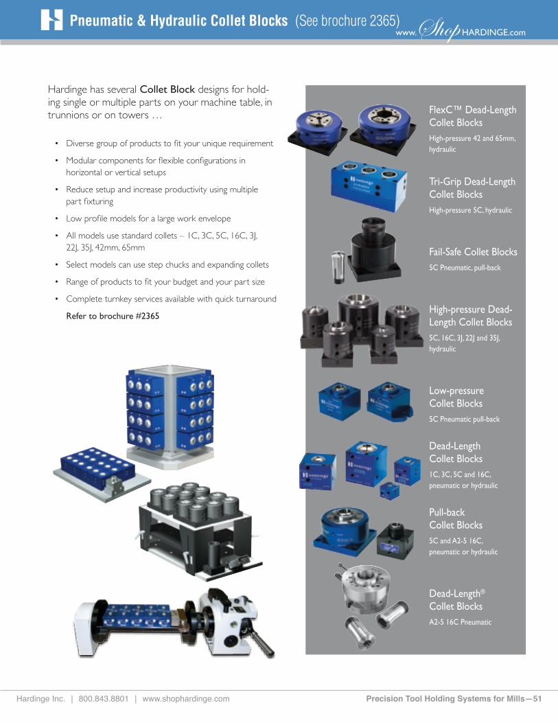
Hardinge Inc. | 800.843.8801 | www.shophardinge.com Precision Tool Holding Systems for Mills—51
www.Shop HARDINGE.comPneumatic & Hydraulic Collet Blocks (See brochure 2365)
FlexC™ Dead-Length Collet BlocksHigh-pressure 42 and 65mm, hydraulic
Tri-Grip Dead-Length Collet BlocksHigh-pressure 5C, hydraulic
Fail-Safe Collet Blocks5C Pneumatic, pull-back
High-pressure Dead-Length Collet Blocks5C, 16C, 3J, 22J and 35J, hydraulic
Low-pressure Collet Blocks5C Pneumatic pull-back
Dead-Length Collet Blocks1C, 3C, 5C and 16C, pneumatic or hydraulic
Pull-back Collet Blocks5C and A2-5 16C, pneumatic or hydraulic
Dead-Length® Collet BlocksA2-5 16C Pneumatic
Hardinge has several Collet Block designs for hold-ing single or multiple parts on your machine table, in trunnions or on towers …
• Diverse group of products to fit your unique requirement
• Modular components for flexible configurations in horizontal or vertical setups
• Reduce setup and increase productivity using multiple part fixturing
• Low profile models for a large work envelope
• All models use standard collets – 1C, 3C, 5C, 16C, 3J, 22J, 35J, 42mm, 65mm
• Select models can use step chucks and expanding collets
• Range of products to fit your budget and your part size
• Complete turnkey services available with quick turnaround
Refer to brochure #2365

All specifications subject to change without notice.
All marks indicated by ® and ™ are trademarks of
their respective owners. #2350D • Litho in USA
• ©Hardinge Inc. 2014 • November 2014
Over the years, The Hardinge Group™ steadily diversified both its product offerings and operations. Today, the company has grown into a globally diversified player with manufacturing operations in North America, Europe and Asia. In addition to designing and building turning centers, and collets, Hardinge is a world leader in grinding solutions with the addition of the Kellenberger, Jones & Shipman, Hauser, Tschudin, Usach and Voumard brands to the Hardinge family. The company also designs and manufactures Bridgeport machining centers and other industrial products for a wide range of material cutting, turnkey automation and workholding needs.
Expect more from your Hardinge products. Choose Hardinge precision and reliability for increased productivity and value!
Call us today, we’ve got your answer.
HARDINGECOMPANIESWORLDWIDE
North AmericaHardinge Inc. General Information: 607-734-2281 Sales Fax: 607.734.8819 Workholding Fax: 607.734.3886 Service: 800.424.2440 www.hardinge.com
Canada Canadian Hardinge Machine Tools Ltd. Tel: 800.468.5946 Fax: 607.734.8819
China Hardinge Machine (Shanghai) Co. Ltd.Hardinge China Limited Tel: 0086 21 38108686 Fax: 0086 21 38108681
Hardinge Precision Machinery (Jiaxing) Co., Ltd.Economic and Technology Development Zone Tel: 0573-82601088 Fax: 0573-82601988
Germany Hardinge GmbH Tel: (49) 2151 496490 Fax: (49) 2151 4964999
Taiwan Hardinge Machine Tools B.V. Tel: 886 49 2260536 Fax: 886 49 2252203 [email protected]
Switzerland L. Kellenberger & Co. AG Tel: +41 (0) 71 242 91 11 Fax: +41 (0) 71 242 92 22 [email protected] www.kellenberger.net
L. Kellenberger & Co. AG Tel: +41 (0)32 344 11 52 Fax: +41 (0)32 341 13 93 [email protected] www.kellenberger.net
United KingdomJones & Shipman Hardinge Tel: +44 (0) 116 2013000 Fax: +44 (0) 116 2013002 [email protected] www.jonesshipman.com