precision high speed photography trigger tutorial-ver 1.3 20120714
TRANSCRIPT
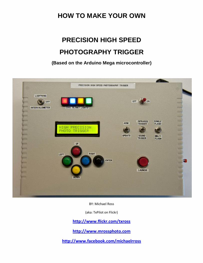
HOW TO MAKE YOUR OWN
PRECISION HIGH SPEED
PHOTOGRAPHY TRIGGER (Based on the Arduino Mega microcontroller)
BY: Michael Ross
(aka: TxPilot on Flickr)
http://www.flickr.com/txross
http://www.mrossphoto.com
http://www.facebook.com/michaelrross
How To: Making your own Precision High Speed Photography Trigger
2 Ver 1.3 - 20120714 By: Michael Ross (aka TxPilot on Flickr) Copyright ©2012 – All Rights Reserved
TABLE OF CONTENTS
FORWARD 4 Other Resources & Links 7 THE PARTS LIST 8 TOOLS NEEDED 46 A WORD ON SWITCHES 53 THE WIRING DIAGRAM 56 LAYING THINGS OUT 59 WIRING THE SWITCHES 69 POWER CIRCUITS 71 WIRING THE ARDUINO BOARD 73 WIRING THE BACK PANEL 76 WIRING THE FRONT PANEL 77 LAYING OUT THE REST OF THE CIRCUITS 78 WIRING THE CONNECTORS ON THE ARDUINO 87 FINISHING UP THE MAIN UNIT 92 CABLE WIRING 96 INFRARED CABLE WIRING DIAGRAM 97 SOUND DETECTOR CABLE WIRING DIAGRAM 98 LIGHTNING DETECTOR CABLE WIRING DIAGRAM 99 HOT SHOE ADAPTER CABLE WIRING DIAGRAM 100 PC SYNC CORD ADAPTER WIRING DIAGRAM 101 LAMP CONTROLLER WIRING DIAGRAM 102 OPERATING THE UNIT 103 ADDITIONAL BUILD PHOTOS (for the second unit I made) 106
How To: Making your own Precision High Speed Photography Trigger
3 Ver 1.3 - 20120714 By: Michael Ross (aka TxPilot on Flickr) Copyright ©2012 – All Rights Reserved
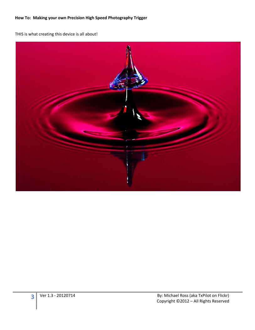
THIS is what creating this device is all about!
How To: Making your own Precision High Speed Photography Trigger
4 Ver 1.3 - 20120714 By: Michael Ross (aka TxPilot on Flickr) Copyright ©2012 – All Rights Reserved
Forward
Well, if you are reading this, then you probably are interested in making one of these of your very own! But before you make your decision, please read through the entire document and make sure this is something that you really want to take on. I tried to keep this as detailed and simple as possible, but even so, there is a level of complexity that some might not feel comfortable in handling.
Now, since I spent all this time creating this unit and the tutorial to go along with it, I am going to ask for a few things in return if you decided to take this project on. First of all, anytime I do something for others like this, there IS always at least one catch! PAY IT FORWARD!! Someone has done something nice for you and now you are obligated to that for someone else! It is not hard, not even difficult. Just make sure it is an act worthy of “payment” for what I have done for you! Fair enough!? The second thing is, please do not post any of the details of this tutorial or its content anywhere without a link back to my website. That’s it! See, that wasn’t too painful! And you definitely can’t beat the price! ;-)
Okay, now first of all, this build up is mainly a combination of circuits and other builds that were created by others with information found on the internet. I want to make it perfectly clear that I did not invent any of this! I might have tweaked a few circuits or worked my way around some things to keep things simple, but all I can really lay claim to is making this particular device in this particular way! The coding for the Arduino is entirely created by me and was totally written from scratch as well. And with that being said, I am NO professional programmer! Yes, I know how to program things in a logical order, but I am sure there is a LOT that can be done to make my coding more efficient. So don’t pick apart my code and tell me how bad of a programmer I am!! I won’t listen even if you do! ;-) Now if you want to make it more efficient, then by all means, do so! Then share with everyone else! There are others that have made triggers similar to this and there are also “off the shelf” units that can be purchased which you can get running without even lifting a soldering iron. But I had my own ideas on what I wanted this unit to do and I wanted to make it flexible enough to be able to add other functionality to it down the road as well, so I went the DIY route. Another reason for the DIY route was basically to get more functionality for my money. ;-) Besides, I always like the satisfaction of saying that I did it myself.
I have wanted to make a unit like this for several years but have just not had the time to put into doing it until recently. The plus side to that is that I have had a long time to think about what I wanted the unit to do and what features I would like to build into it. So, before I started to actually heat up the soldering iron and get started on it, I sat down and listed out everything that I wanted the unit to do “in my perfect world”. Here is that list:
1) Control up to 4 solenoid valves 2) Control up to 4 strobes 3) Allow any number of drops to be released 4) Allow control over the size of the drops released 5) Allow control over the delay time between drops 6) Control the Camera Shutter (open and close) in bulb mode 7) Control up to two lamps for room lighting between shots 8) Provide Sound and IR Triggers
How To: Making your own Precision High Speed Photography Trigger
5 Ver 1.3 - 20120714 By: Michael Ross (aka TxPilot on Flickr) Copyright ©2012 – All Rights Reserved
These are really not unrealistic requirements at all, BUT… in the back of my mind I knew that I wanted to accomplish this by creating simple circuits that anyone could make, keep it flexible to allow for changes and additions down the road, and make a unit that I would be proud to show off to others! Plus, I wanted to make a tutorial for others to do the same so I knew I HAD to keep it simple for non-electronics type folks to follow!
I didn’t keep track of the time it took me to develop and make this unit, but it was about three weeks from start to finish with an average of about 14-16 hours each day. This included a few days worth of hunting down and either ordering parts or going to pick them up locally. It also included a lot of testing and circuit design and ton of time writing all of the code along with a few days lost due to debugging errors that could NOT be debugged! So I have maybe about 300 plus hours into it. I would imagine it would take about 40 hours or so to put one of these together if all you had to do was purchase the parts and put them all together. That is a pretty wild guess though. It would greatly depend on the skills of the person doing it and how well I put together this tutorial! Ha! So you can always blame it on me if it takes longer! ;-)
Okay, so keeping all of that in mind, I knew I needed a microcontroller to be the “heart” of the unit and I already had a good idea what that was going to be when I started. Since most of my experience has been with the Arduino line of open source microcontrollers and the fact that I have several of them lying around made this an easy choice! I decided to use the Arduino Mega 2560 due to its memory size and the sheer number of input/output pins available on the board. I knew that it would take a LOT to hit a limit in either one of these if I chose that board, so that is what I ran with. Also, since this is a very popular microcontroller, there is a ton of information and support that can be found on the internet related to it.
If you are contemplating taking on this project, it is possible to use some of the smaller, cheaper Arduino boards available out there. Also, since Arduino is open source, there are many Arduino “Clones” available out there as well that work exactly like the Arduino. If you only want to build a part of this project, just the sound trigger or lightning trigger for example, then you can go with a much smaller Arduino since you will need fewer ports available on the board itself.
One of my goals with this tutorial is to try to make it as NON-Technical as possible so that a novice with electronics (but someone with at least some DIY skills) could make one of these and get it working. I have already gone too far by talking about micro-controllers, memory, and ports so don’t be intimidated by that. You do not need to know anything about all of that to make this work. But, as I said, you DO need at least a little knowledge in the DIY department. I am not going to get into the nitty gritty of laying things out and cutting and drilling holes to mount all of the switches and display. If that is not something you are sure you can handle, then I would suggest getting some help or purchasing an off the shelf solution instead.
One the flip side of all of that, if you are geek by any geek standards, then by all means, apply your geekiness to your own version! ;-) I know there are plenty of ways to go about all of this, so if you have another way, then just do it. It would be nice if you would share your addition or changes with the rest of the world in the process of it all though. Consider it a “Pay it Forward” type thing! ;-) Now you are obligated! ;-)
But most of all… ENJOY!! And I hope you learn something along the way!
How To: Making your own Precision High Speed Photography Trigger
6 Ver 1.3 - 20120714 By: Michael Ross (aka TxPilot on Flickr) Copyright ©2012 – All Rights Reserved
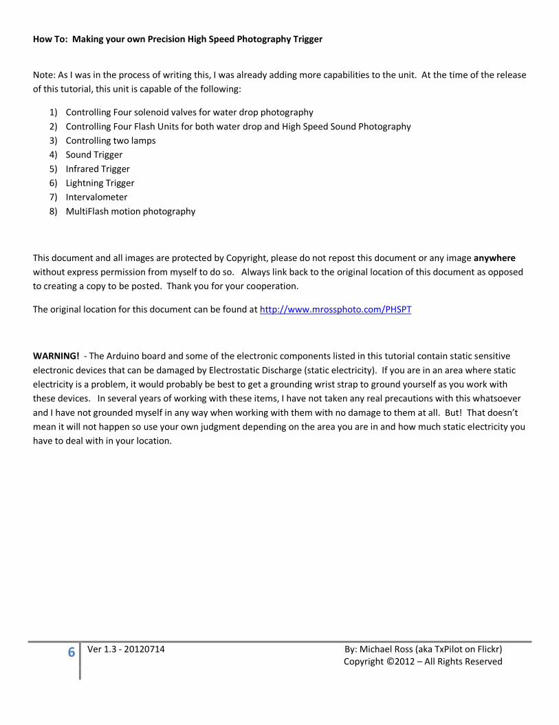
Note: As I was in the process of writing this, I was already adding more capabilities to the unit. At the time of the release of this tutorial, this unit is capable of the following:
1) Controlling Four solenoid valves for water drop photography 2) Controlling Four Flash Units for both water drop and High Speed Sound Photography 3) Controlling two lamps 4) Sound Trigger 5) Infrared Trigger 6) Lightning Trigger 7) Intervalometer 8) MultiFlash motion photography
This document and all images are protected by Copyright, please do not repost this document or any image anywhere without express permission from myself to do so. Always link back to the original location of this document as opposed to creating a copy to be posted. Thank you for your cooperation.
The original location for this document can be found at http://www.mrossphoto.com/PHSPT
WARNING! - The Arduino board and some of the electronic components listed in this tutorial contain static sensitive electronic devices that can be damaged by Electrostatic Discharge (static electricity). If you are in an area where static electricity is a problem, it would probably be best to get a grounding wrist strap to ground yourself as you work with these devices. In several years of working with these items, I have not taken any real precautions with this whatsoever and I have not grounded myself in any way when working with them with no damage to them at all. But! That doesn’t mean it will not happen so use your own judgment depending on the area you are in and how much static electricity you have to deal with in your location.
How To: Making your own Precision High Speed Photography Trigger
7 Ver 1.3 - 20120714 By: Michael Ross (aka TxPilot on Flickr) Copyright ©2012 – All Rights Reserved
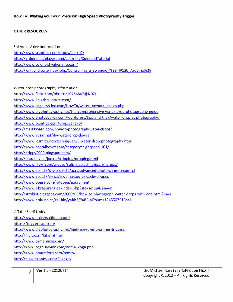
OTHER RESOURCES
Solenoid Valve Information http://www.scantips.com/drops/shako2/ http://arduino.cc/playground/Learning/SolenoidTutorial http://www.solenoid-valve-info.com/ http://wiki.bildr.org/index.php/Controlling_a_solenoid_%28TIP120_Arduino%29 Water drop photography information http://www.flickr.com/photos/10756887@N07/ http://www.liquidsculpture.com/ http://www.cognisys-inc.com/HowTo/water_beyond_basics.php http://www.diyphotography.net/the-comprehensive-water-drop-photography-guide http://www.photosbykev.com/wordpress/tips-and-trick/water-droplet-photography/ http://www.scantips.com/drops/shako/ http://markkneen.com/how-to-photograph-water-drops/ http://www.vdsar.net/diy-waterdrop-device http://www.iesmith.net/technique/23-water-drop-photography.html http://www.pascalbovet.com/category/highspeed-101/ http://drippy2009.blogspot.com/ http://mural.uv.es/jocasa/dripping/dripping.html http://www.flickr.com/groups/splish_splash_drips_n_drops/ http://www.apcc.tk/diy-projects/apcc-advanced-photo-camera-control http://www.apcc.tk/news/arduino-source-code-of-apcc http://www.pbase.com/fotoopa/equipment http://www.t-braeuning.de/index.php?ste=setup&lan=en http://strobist.blogspot.com/2009/05/how-to-photograph-water-drops-with-one.html?m=1 http://www.arduino.cc/cgi-bin/yabb2/YaBB.pl?num=1245507913/all Off the Shelf Units http://www.universaltimer.com/ https://triggertrap.com/ http://www.diyphotography.net/high-speed-into-primer-triggers http://hiviz.com/kits/mt.htm http://www.cameraaxe.com/ http://www.cognisys-inc.com/home_cogn.php http://www.bmumford.com/photo/ http://quaketronics.com/flashkit/
How To: Making your own Precision High Speed Photography Trigger
8 Ver 1.3 - 20120714 By: Michael Ross (aka TxPilot on Flickr) Copyright ©2012 – All Rights Reserved
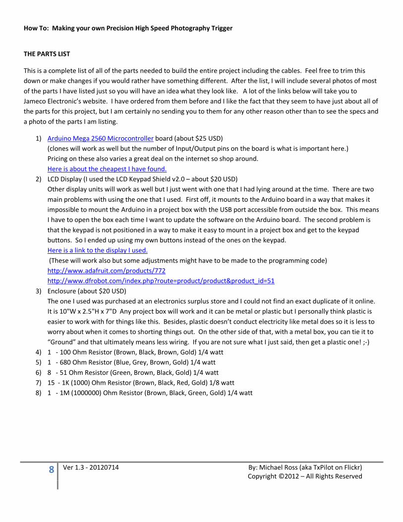
THE PARTS LIST
This is a complete list of all of the parts needed to build the entire project including the cables. Feel free to trim this down or make changes if you would rather have something different. After the list, I will include several photos of most of the parts I have listed just so you will have an idea what they look like. A lot of the links below will take you to Jameco Electronic’s website. I have ordered from them before and I like the fact that they seem to have just about all of the parts for this project, but I am certainly no sending you to them for any other reason other than to see the specs and a photo of the parts I am listing.
1) Arduino Mega 2560 Microcontroller board (about $25 USD) (clones will work as well but the number of Input/Output pins on the board is what is important here.) Pricing on these also varies a great deal on the internet so shop around. Here is about the cheapest I have found.
2) LCD Display (I used the LCD Keypad Shield v2.0 – about $20 USD) Other display units will work as well but I just went with one that I had lying around at the time. There are two main problems with using the one that I used. First off, it mounts to the Arduino board in a way that makes it impossible to mount the Arduino in a project box with the USB port accessible from outside the box. This means I have to open the box each time I want to update the software on the Arduino board. The second problem is that the keypad is not positioned in a way to make it easy to mount in a project box and get to the keypad buttons. So I ended up using my own buttons instead of the ones on the keypad. Here is a link to the display I used. (These will work also but some adjustments might have to be made to the programming code) http://www.adafruit.com/products/772 http://www.dfrobot.com/index.php?route=product/product&product_id=51
3) Enclosure (about $20 USD) The one I used was purchased at an electronics surplus store and I could not find an exact duplicate of it online. It is 10"W x 2.5"H x 7"D Any project box will work and it can be metal or plastic but I personally think plastic is easier to work with for things like this. Besides, plastic doesn’t conduct electricity like metal does so it is less to worry about when it comes to shorting things out. On the other side of that, with a metal box, you can tie it to “Ground” and that ultimately means less wiring. If you are not sure what I just said, then get a plastic one! ;-)
4) 1 - 100 Ohm Resistor (Brown, Black, Brown, Gold) 1/4 watt 5) 1 - 680 Ohm Resistor (Blue, Grey, Brown, Gold) 1/4 watt 6) 8 - 51 Ohm Resistor (Green, Brown, Black, Gold) 1/4 watt 7) 15 - 1K (1000) Ohm Resistor (Brown, Black, Red, Gold) 1/8 watt 8) 1 - 1M (1000000) Ohm Resistor (Brown, Black, Green, Gold) 1/4 watt
How To: Making your own Precision High Speed Photography Trigger
9 Ver 1.3 - 20120714 By: Michael Ross (aka TxPilot on Flickr) Copyright ©2012 – All Rights Reserved
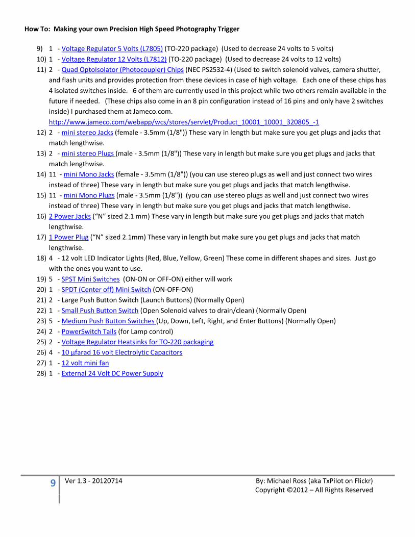
9) 1 - Voltage Regulator 5 Volts (L7805) (TO-220 package) (Used to decrease 24 volts to 5 volts) 10) 1 - Voltage Regulator 12 Volts (L7812) (TO-220 package) (Used to decrease 24 volts to 12 volts) 11) 2 - Quad OptoIsolator (Photocoupler) Chips (NEC PS2532-4) (Used to switch solenoid valves, camera shutter,
and flash units and provides protection from these devices in case of high voltage. Each one of these chips has 4 isolated switches inside. 6 of them are currently used in this project while two others remain available in the future if needed. (These chips also come in an 8 pin configuration instead of 16 pins and only have 2 switches inside) I purchased them at Jameco.com. http://www.jameco.com/webapp/wcs/stores/servlet/Product_10001_10001_320805_-1
12) 2 - mini stereo Jacks (female - 3.5mm (1/8")) These vary in length but make sure you get plugs and jacks that match lengthwise.
13) 2 - mini stereo Plugs (male - 3.5mm (1/8")) These vary in length but make sure you get plugs and jacks that match lengthwise.
14) 11 - mini Mono Jacks (female - 3.5mm (1/8")) (you can use stereo plugs as well and just connect two wires instead of three) These vary in length but make sure you get plugs and jacks that match lengthwise.
15) 11 - mini Mono Plugs (male - 3.5mm (1/8")) (you can use stereo plugs as well and just connect two wires instead of three) These vary in length but make sure you get plugs and jacks that match lengthwise.
16) 2 Power Jacks (“N” sized 2.1 mm) These vary in length but make sure you get plugs and jacks that match lengthwise.
17) 1 Power Plug (“N” sized 2.1mm) These vary in length but make sure you get plugs and jacks that match lengthwise.
18) 4 - 12 volt LED Indicator Lights (Red, Blue, Yellow, Green) These come in different shapes and sizes. Just go with the ones you want to use.
19) 5 - SPST Mini Switches (ON-ON or OFF-ON) either will work 20) 1 - SPDT (Center off) Mini Switch (ON-OFF-ON) 21) 2 - Large Push Button Switch (Launch Buttons) (Normally Open) 22) 1 - Small Push Button Switch (Open Solenoid valves to drain/clean) (Normally Open) 23) 5 - Medium Push Button Switches (Up, Down, Left, Right, and Enter Buttons) (Normally Open) 24) 2 - PowerSwitch Tails (for Lamp control) 25) 2 - Voltage Regulator Heatsinks for TO-220 packaging 26) 4 - 10 µfarad 16 volt Electrolytic Capacitors 27) 1 - 12 volt mini fan 28) 1 - External 24 Volt DC Power Supply
How To: Making your own Precision High Speed Photography Trigger
10 Ver 1.3 - 20120714 By: Michael Ross (aka TxPilot on Flickr) Copyright ©2012 – All Rights Reserved
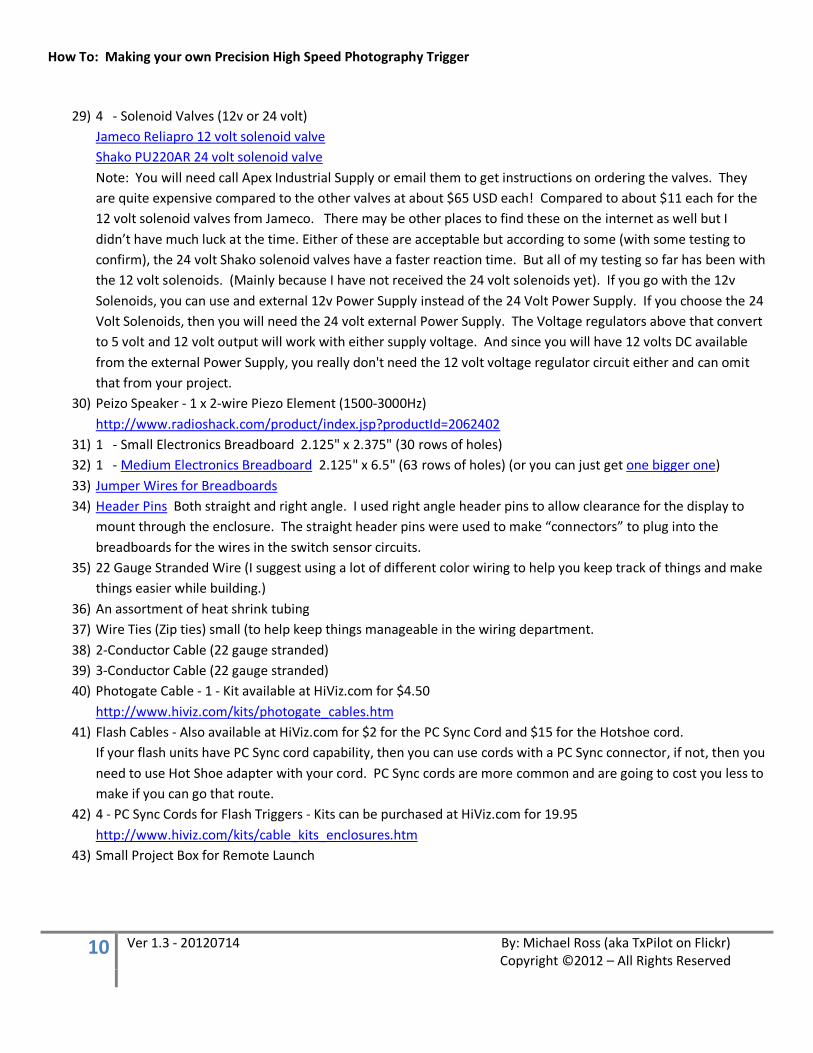
29) 4 - Solenoid Valves (12v or 24 volt) Jameco Reliapro 12 volt solenoid valve Shako PU220AR 24 volt solenoid valve Note: You will need call Apex Industrial Supply or email them to get instructions on ordering the valves. They are quite expensive compared to the other valves at about $65 USD each! Compared to about $11 each for the 12 volt solenoid valves from Jameco. There may be other places to find these on the internet as well but I didn’t have much luck at the time. Either of these are acceptable but according to some (with some testing to confirm), the 24 volt Shako solenoid valves have a faster reaction time. But all of my testing so far has been with the 12 volt solenoids. (Mainly because I have not received the 24 volt solenoids yet). If you go with the 12v Solenoids, you can use and external 12v Power Supply instead of the 24 Volt Power Supply. If you choose the 24 Volt Solenoids, then you will need the 24 volt external Power Supply. The Voltage regulators above that convert to 5 volt and 12 volt output will work with either supply voltage. And since you will have 12 volts DC available from the external Power Supply, you really don't need the 12 volt voltage regulator circuit either and can omit that from your project.
30) Peizo Speaker - 1 x 2-wire Piezo Element (1500-3000Hz) http://www.radioshack.com/product/index.jsp?productId=2062402
31) 1 - Small Electronics Breadboard 2.125" x 2.375" (30 rows of holes) 32) 1 - Medium Electronics Breadboard 2.125" x 6.5" (63 rows of holes) (or you can just get one bigger one) 33) Jumper Wires for Breadboards 34) Header Pins Both straight and right angle. I used right angle header pins to allow clearance for the display to
mount through the enclosure. The straight header pins were used to make “connectors” to plug into the breadboards for the wires in the switch sensor circuits.
35) 22 Gauge Stranded Wire (I suggest using a lot of different color wiring to help you keep track of things and make things easier while building.)
36) An assortment of heat shrink tubing 37) Wire Ties (Zip ties) small (to help keep things manageable in the wiring department. 38) 2-Conductor Cable (22 gauge stranded) 39) 3-Conductor Cable (22 gauge stranded) 40) Photogate Cable - 1 - Kit available at HiViz.com for $4.50
http://www.hiviz.com/kits/photogate_cables.htm 41) Flash Cables - Also available at HiViz.com for $2 for the PC Sync Cord and $15 for the Hotshoe cord.
If your flash units have PC Sync cord capability, then you can use cords with a PC Sync connector, if not, then you need to use Hot Shoe adapter with your cord. PC Sync cords are more common and are going to cost you less to make if you can go that route.
42) 4 - PC Sync Cords for Flash Triggers - Kits can be purchased at HiViz.com for 19.95 http://www.hiviz.com/kits/cable_kits_enclosures.htm
43) Small Project Box for Remote Launch

How To: Making your own Precision High Speed Photography Trigger
11 Ver 1.3 - 20120714 By: Michael Ross (aka TxPilot on Flickr) Copyright ©2012 – All Rights Reserved
44) Nikon Shutter Release Cable (Do a search on Google for DIY remote releases for Canon or other cameras. Canon remotes are much easier to make than the Nikon remotes are.) You will need some 3 conductor cable, a Nikon 10 Pin connection, and Stereo Mini Audio Plug. Note: You can purchase a cheap wired remote for your Nikon for under $10 online and then use the handheld portion of it as the Remote Launch Switch and the 10 pin connector to make your Shutter release cable. ;-)
There are some other things that you will need as well to get to the final stage of taking photos of water drops. Things like bottles to hold liquid for the drop supply reservoirs and some fish tank air tubing to run supply lines to your valves. You will also need to construct a stand to hold your valves over a drip pan and some way to support backgrounds, etc. along with your strobes for lighting your water drops. But I will go over some of that at the end of this tutorial so you will have an idea of what to go for.
All of this is a lot of work and even working with liquids during drop photography sessions can be some work in itself, but the reward is getting some great shots out of it.

How To: Making your own Precision High Speed Photography Trigger
12 Ver 1.3 - 20120714 By: Michael Ross (aka TxPilot on Flickr) Copyright ©2012 – All Rights Reserved
Here are some photos of most of the key parts for the unit and accessories such as specialty cables that you will need to make to make it all work.
THE ARDUINO MEGA 2560
The “Brains” of the box! Of course it is not super smart because it is only thinking inside the box! ;-) Unless you remove it, then it will be thinking outside of the box! ;-)
You will need to download and install the Arduino software (known as the IDE or Integrated Development Environment) from the Arduino website.
http://arduino.cc/en/Main/Software
You will also need to install the drivers for the Arduino board as well and these are included in the download.
Note: Some have had to download and install the VCP (Virtual Com Port) drivers from the FTDI website located at
http://www.ftdichip.com/Drivers/VCP.htm
How To: Making your own Precision High Speed Photography Trigger
13 Ver 1.3 - 20120714 By: Michael Ross (aka TxPilot on Flickr) Copyright ©2012 – All Rights Reserved
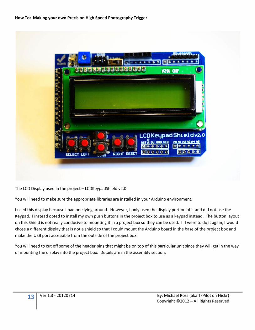
The LCD Display used in the project – LCDKeypadShield v2.0
You will need to make sure the appropriate libraries are installed in your Arduino environment.
I used this display because I had one lying around. However, I only used the display portion of it and did not use the Keypad. I instead opted to install my own push buttons in the project box to use as a keypad instead. The button layout on this Shield is not really conducive to mounting it in a project box so they can be used. If I were to do it again, I would chose a different display that is not a shield so that I could mount the Arduino board in the base of the project box and make the USB port accessible from the outside of the project box.
You will need to cut off some of the header pins that might be on top of this particular unit since they will get in the way of mounting the display into the project box. Details are in the assembly section.

How To: Making your own Precision High Speed Photography Trigger
14 Ver 1.3 - 20120714 By: Michael Ross (aka TxPilot on Flickr) Copyright ©2012 – All Rights Reserved
If you decide to go with a larger or different display, make sure it is one that has a library available for it to be used on the Arduino and that you have a wiring diagram on how to connect it to the Arduino.
If I were to do this project again, (and I am working on a second unit already!) Then I would choose one of the the 4x20 LCD displays that use the same libraries and connections that the unit used in this tutorial has.
http://www.adafruit.com/products/198
http://www.adafruit.com/products/499
http://www.adafruit.com/products/498
A Tutorial on how to connect up and use these displays with the Arduino can be found on the Ladyada.net website at:
http://www.ladyada.net/learn/lcd/charlcd.html
How To: Making your own Precision High Speed Photography Trigger
15 Ver 1.3 - 20120714 By: Michael Ross (aka TxPilot on Flickr) Copyright ©2012 – All Rights Reserved
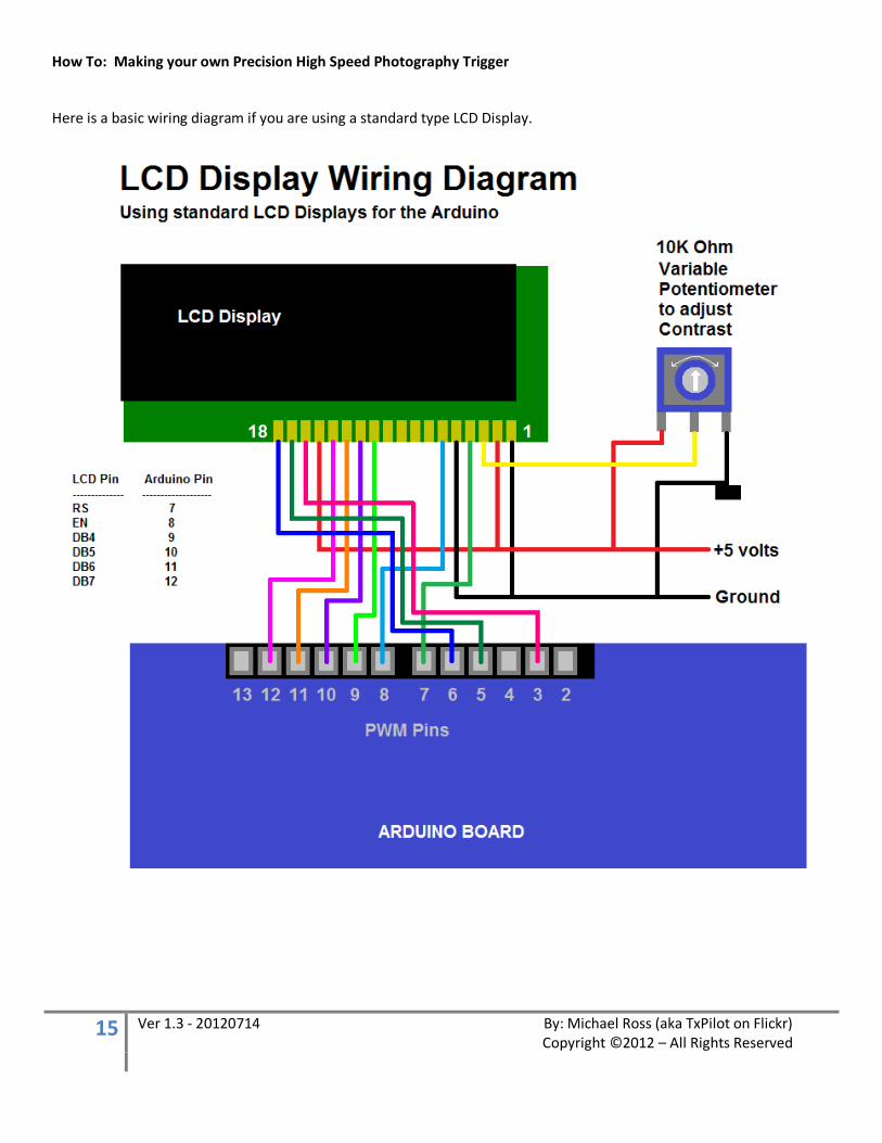
Here is a basic wiring diagram if you are using a standard type LCD Display.
How To: Making your own Precision High Speed Photography Trigger
16 Ver 1.3 - 20120714 By: Michael Ross (aka TxPilot on Flickr) Copyright ©2012 – All Rights Reserved
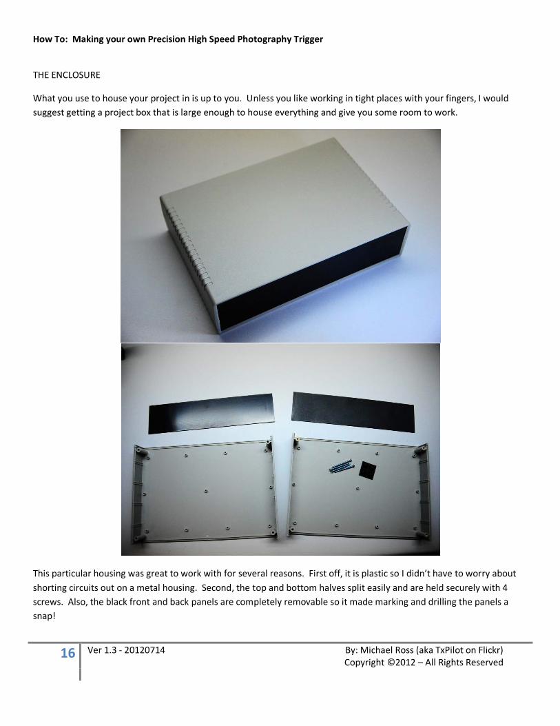
THE ENCLOSURE
What you use to house your project in is up to you. Unless you like working in tight places with your fingers, I would suggest getting a project box that is large enough to house everything and give you some room to work.
This particular housing was great to work with for several reasons. First off, it is plastic so I didn’t have to worry about shorting circuits out on a metal housing. Second, the top and bottom halves split easily and are held securely with 4 screws. Also, the black front and back panels are completely removable so it made marking and drilling the panels a snap!

How To: Making your own Precision High Speed Photography Trigger
17 Ver 1.3 - 20120714 By: Michael Ross (aka TxPilot on Flickr) Copyright ©2012 – All Rights Reserved
Optocoupler (Photocoupler Chip)
This device is really just a light powered switch. Actually there are 4 light powered switches inside this DIP (Dual Inline Package). Notice there is a dot in the corner on the top of the DIP. This identifies pin number 1 on the package.
The advantage of using these for this type of application is that the circuits are physically disconnected inside. Light is used on one side, to activate the switch on the other so it ultimately isolates things like your flash units and camera from the rest of the circuitry and gives those devices protection in case something goes wrong. This was the ONLY way I was going to connect my $2500 Nikon body and another $2K in flash units to it! ;-) I just wanted you to know this so that you would feel more comfortable in connecting your own camera and flash units to it. Believe me, if I thought there was any risk to my camera or flash units, I would NOT have connected them to it!
How To: Making your own Precision High Speed Photography Trigger
18 Ver 1.3 - 20120714 By: Michael Ross (aka TxPilot on Flickr) Copyright ©2012 – All Rights Reserved
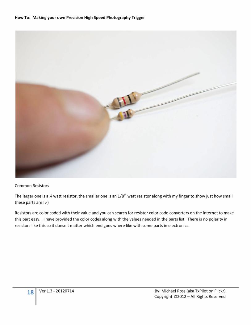
Common Resistors
The larger one is a ¼ watt resistor, the smaller one is an 1/8th watt resistor along with my finger to show just how small these parts are! ;-)
Resistors are color coded with their value and you can search for resistor color code converters on the internet to make this part easy. I have provided the color codes along with the values needed in the parts list. There is no polarity in resistors like this so it doesn’t matter which end goes where like with some parts in electronics.
How To: Making your own Precision High Speed Photography Trigger
19 Ver 1.3 - 20120714 By: Michael Ross (aka TxPilot on Flickr) Copyright ©2012 – All Rights Reserved
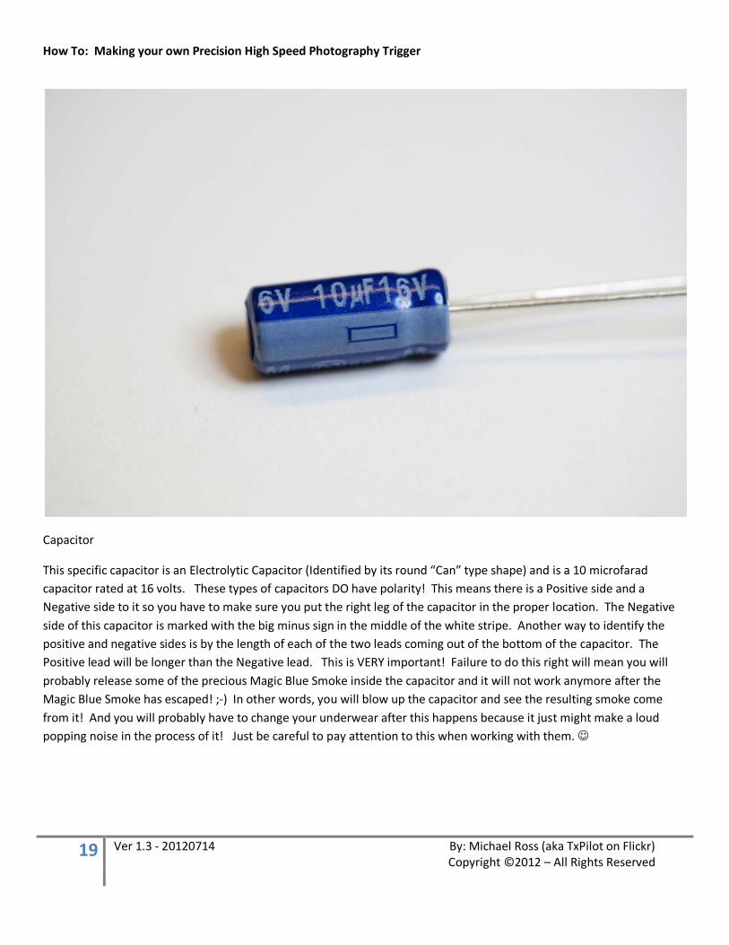
Capacitor
This specific capacitor is an Electrolytic Capacitor (Identified by its round “Can” type shape) and is a 10 microfarad capacitor rated at 16 volts. These types of capacitors DO have polarity! This means there is a Positive side and a Negative side to it so you have to make sure you put the right leg of the capacitor in the proper location. The Negative side of this capacitor is marked with the big minus sign in the middle of the white stripe. Another way to identify the positive and negative sides is by the length of each of the two leads coming out of the bottom of the capacitor. The Positive lead will be longer than the Negative lead. This is VERY important! Failure to do this right will mean you will probably release some of the precious Magic Blue Smoke inside the capacitor and it will not work anymore after the Magic Blue Smoke has escaped! ;-) In other words, you will blow up the capacitor and see the resulting smoke come from it! And you will probably have to change your underwear after this happens because it just might make a loud popping noise in the process of it! Just be careful to pay attention to this when working with them.

How To: Making your own Precision High Speed Photography Trigger
20 Ver 1.3 - 20120714 By: Michael Ross (aka TxPilot on Flickr) Copyright ©2012 – All Rights Reserved
“N” size Power plug and jack.
It really doesn’t matter which size you use on these, just make sure you are consistent and that the plug and jack fit together properly. I used these in two places. One for the power jack that the external 24 volt power supply plugs into, and one for the remote launch button.

How To: Making your own Precision High Speed Photography Trigger
21 Ver 1.3 - 20120714 By: Michael Ross (aka TxPilot on Flickr) Copyright ©2012 – All Rights Reserved
Stereo and Mono Audio Plugs
The Stereo plug is on top and has two black bands on the small plug portion. This means it has three connections and is used for those connections that need three wires running to it.
The Mono plug is on bottom and has a single black band on the small plug portion. This means it only has two connections instead of three for those connections that just need two wires.
How To: Making your own Precision High Speed Photography Trigger
22 Ver 1.3 - 20120714 By: Michael Ross (aka TxPilot on Flickr) Copyright ©2012 – All Rights Reserved
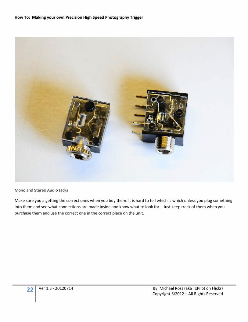
Mono and Stereo Audio Jacks
Make sure you a getting the correct ones when you buy them. It is hard to tell which is which unless you plug something into them and see what connections are made inside and know what to look for. Just keep track of them when you purchase them and use the correct one in the correct place on the unit.
How To: Making your own Precision High Speed Photography Trigger
23 Ver 1.3 - 20120714 By: Michael Ross (aka TxPilot on Flickr) Copyright ©2012 – All Rights Reserved
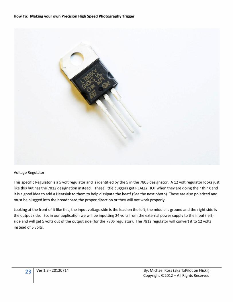
Voltage Regulator
This specific Regulator is a 5 volt regulator and is identified by the 5 in the 7805 designator. A 12 volt regulator looks just like this but has the 7812 designation instead. These little buggers get REALLY HOT when they are doing their thing and it is a good idea to add a Heatsink to them to help dissipate the heat! (See the next photo) These are also polarized and must be plugged into the breadboard the proper direction or they will not work properly.
Looking at the front of it like this, the input voltage side is the lead on the left, the middle is ground and the right side is the output side. So, in our application we will be inputting 24 volts from the external power supply to the input (left) side and will get 5 volts out of the output side (for the 7805 regulator). The 7812 regulator will convert it to 12 volts instead of 5 volts.

How To: Making your own Precision High Speed Photography Trigger
24 Ver 1.3 - 20120714 By: Michael Ross (aka TxPilot on Flickr) Copyright ©2012 – All Rights Reserved
Heatsinks (with voltage regulators attached to them)
Heatsinks are nothing more really that aluminum fins that pull the heat away from the voltage regulator and dissipate it into the air. The larger the heatsink, the more efficient it is in doing its job.
I have also added a mini fan to this build to help air flow through the box which will also help the heatsinks do their job.
How To: Making your own Precision High Speed Photography Trigger
25 Ver 1.3 - 20120714 By: Michael Ross (aka TxPilot on Flickr) Copyright ©2012 – All Rights Reserved
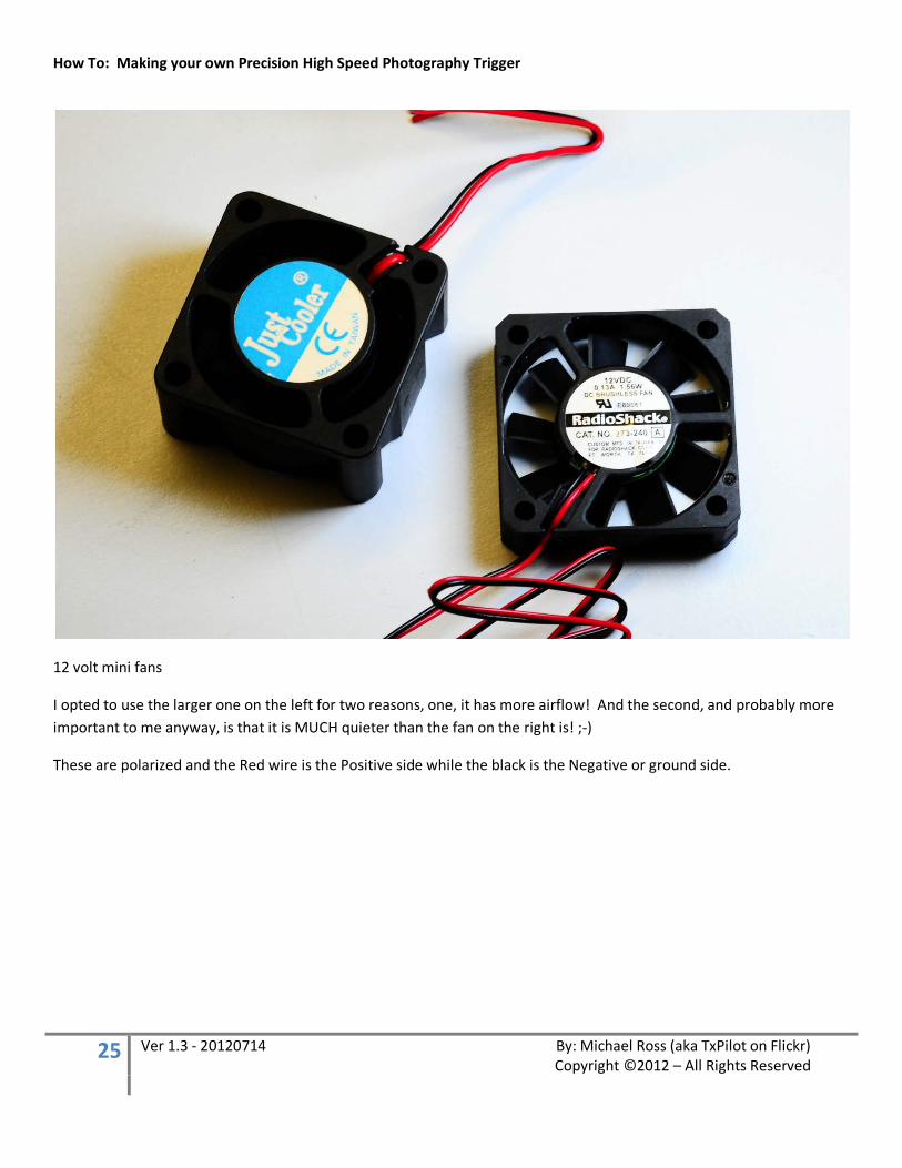
12 volt mini fans
I opted to use the larger one on the left for two reasons, one, it has more airflow! And the second, and probably more important to me anyway, is that it is MUCH quieter than the fan on the right is! ;-)
These are polarized and the Red wire is the Positive side while the black is the Negative or ground side.
How To: Making your own Precision High Speed Photography Trigger
26 Ver 1.3 - 20120714 By: Michael Ross (aka TxPilot on Flickr) Copyright ©2012 – All Rights Reserved
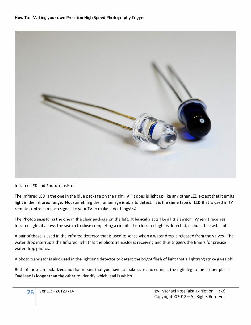
Infrared LED and Phototransistor
The Infrared LED is the one in the blue package on the right. All it does is light up like any other LED except that it emits light in the Infrared range. Not something the human eye is able to detect. It is the same type of LED that is used in TV remote controls to flash signals to your TV to make it do things!
The Phototransistor is the one in the clear package on the left. It basically acts like a little switch. When it receives Infrared light, it allows the switch to close completing a circuit. If no Infrared light is detected, it shuts the switch off.
A pair of these is used in the Infrared detector that is used to sense when a water drop is released from the valves. The water drop interrupts the Infrared light that the phototransistor is receiving and thus triggers the timers for precise water drop photos.
A photo transistor is also used in the lightning detector to detect the bright flash of light that a lightning strike gives off.
Both of these are polarized and that means that you have to make sure and connect the right leg to the proper place. One lead is longer than the other to identify which lead is which.
How To: Making your own Precision High Speed Photography Trigger
27 Ver 1.3 - 20120714 By: Michael Ross (aka TxPilot on Flickr) Copyright ©2012 – All Rights Reserved
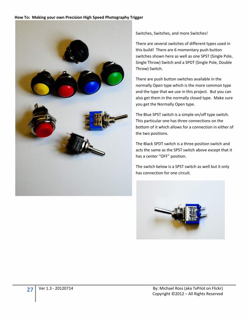
Switches, Switches, and more Switches!
There are several switches of different types used in this build! There are 6 momentary push button switches shown here as well as one SPST (Single Pole, Single Throw) Switch and a SPDT (Single Pole, Double Throw) Switch.
There are push button switches available in the normally Open type which is the more common type and the type that we use in this project. But you can also get them in the normally closed type. Make sure you get the Normally Open type.
The Blue SPST switch is a simple on/off type switch. This particular one has three connections on the bottom of it which allows for a connection in either of the two positions.
The Black SPDT switch is a three position switch and acts the same as the SPST switch above except that it has a center “OFF” position.
The switch below is a SPST switch as well but it only has connection for one circuit.
How To: Making your own Precision High Speed Photography Trigger
28 Ver 1.3 - 20120714 By: Michael Ross (aka TxPilot on Flickr) Copyright ©2012 – All Rights Reserved
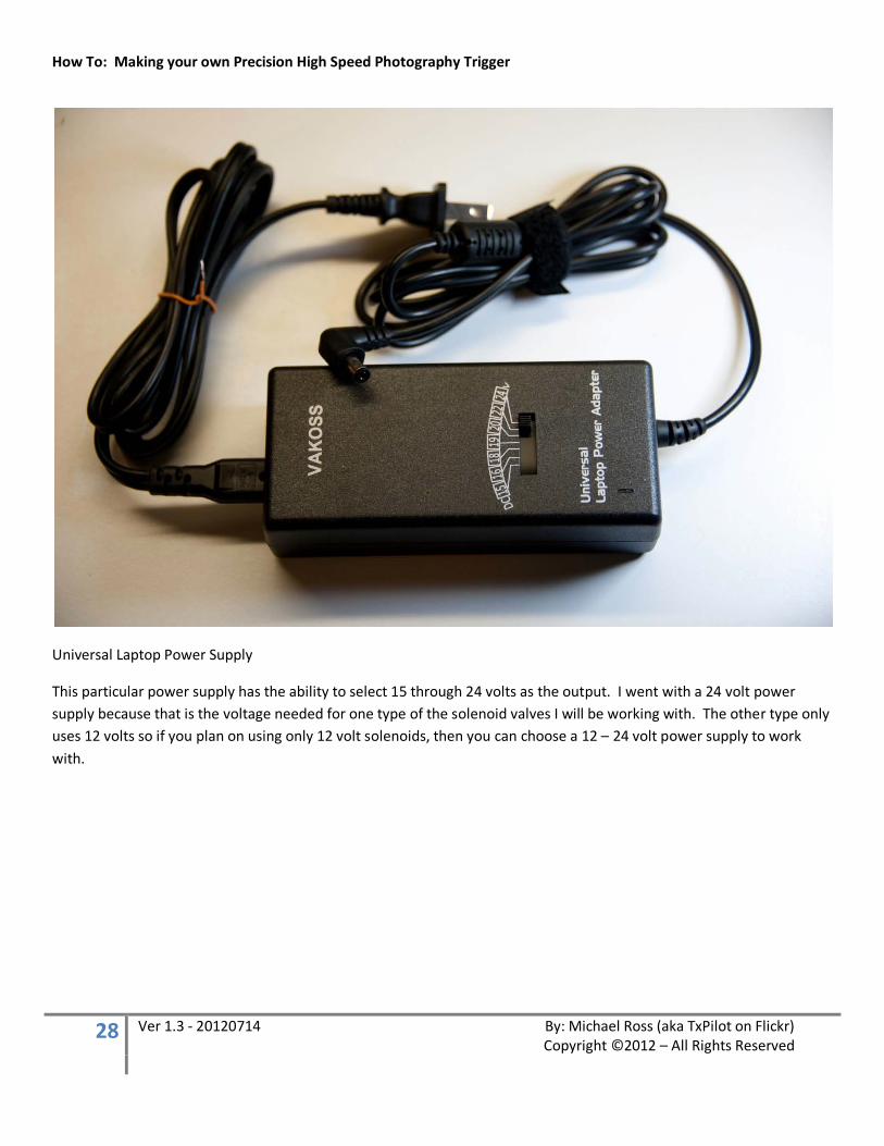
Universal Laptop Power Supply
This particular power supply has the ability to select 15 through 24 volts as the output. I went with a 24 volt power supply because that is the voltage needed for one type of the solenoid valves I will be working with. The other type only uses 12 volts so if you plan on using only 12 volt solenoids, then you can choose a 12 – 24 volt power supply to work with.

How To: Making your own Precision High Speed Photography Trigger
29 Ver 1.3 - 20120714 By: Michael Ross (aka TxPilot on Flickr) Copyright ©2012 – All Rights Reserved
Piezo Speaker
Yes, this is a speaker and these are those annoying things you hear beeping like crazy with those high pitched beeps when you go to fast food place! They are usually going off to let someone know the fries are ready but are usually ignored for too long! ;-)
Speakers and Microphones both basically do the same thing and since the Piezo speakers are really sensitive, they work great as a sound detection device! So this is what we use to detect loud sounds for the Sound Detection portion of the system. :-)
How To: Making your own Precision High Speed Photography Trigger
30 Ver 1.3 - 20120714 By: Michael Ross (aka TxPilot on Flickr) Copyright ©2012 – All Rights Reserved
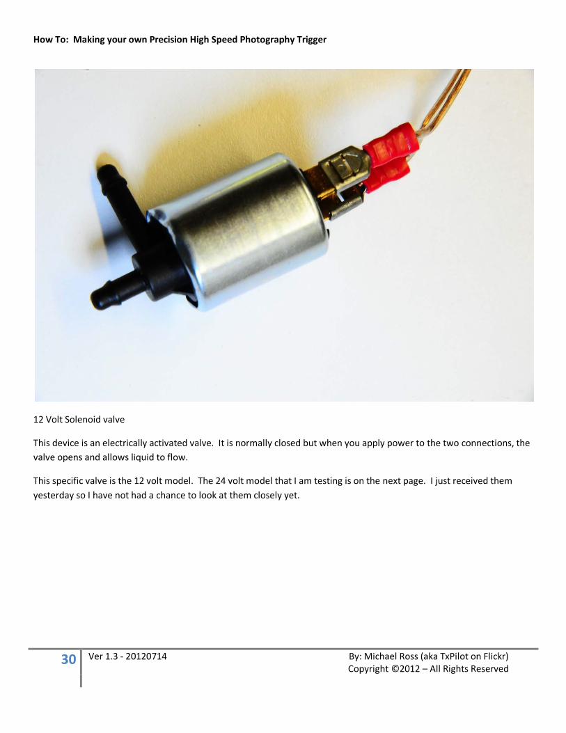
12 Volt Solenoid valve
This device is an electrically activated valve. It is normally closed but when you apply power to the two connections, the valve opens and allows liquid to flow.
This specific valve is the 12 volt model. The 24 volt model that I am testing is on the next page. I just received them yesterday so I have not had a chance to look at them closely yet.
How To: Making your own Precision High Speed Photography Trigger
31 Ver 1.3 - 20120714 By: Michael Ross (aka TxPilot on Flickr) Copyright ©2012 – All Rights Reserved
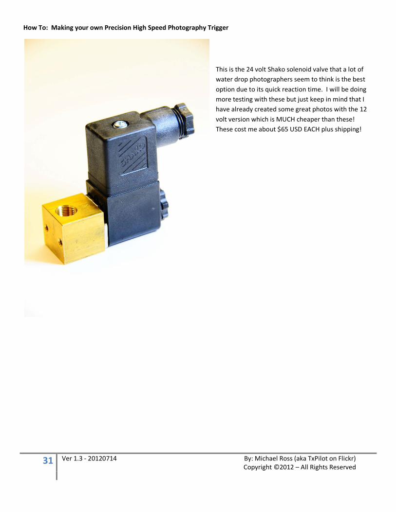
This is the 24 volt Shako solenoid valve that a lot of water drop photographers seem to think is the best option due to its quick reaction time. I will be doing more testing with these but just keep in mind that I have already created some great photos with the 12 volt version which is MUCH cheaper than these! These cost me about $65 USD EACH plus shipping!
How To: Making your own Precision High Speed Photography Trigger
32 Ver 1.3 - 20120714 By: Michael Ross (aka TxPilot on Flickr) Copyright ©2012 – All Rights Reserved
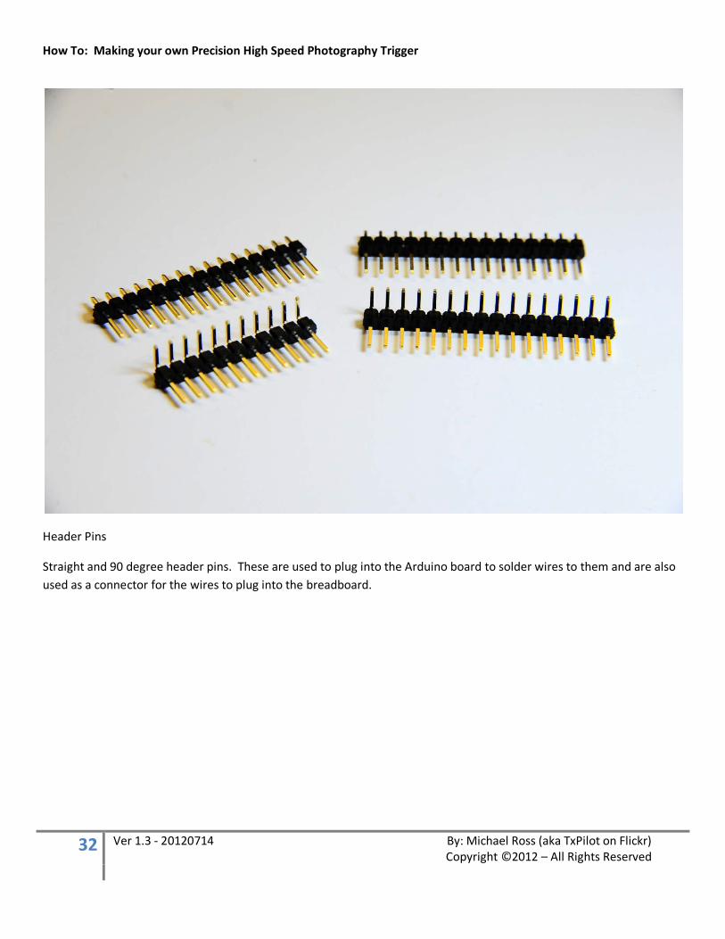
Header Pins
Straight and 90 degree header pins. These are used to plug into the Arduino board to solder wires to them and are also used as a connector for the wires to plug into the breadboard.
How To: Making your own Precision High Speed Photography Trigger
33 Ver 1.3 - 20120714 By: Michael Ross (aka TxPilot on Flickr) Copyright ©2012 – All Rights Reserved
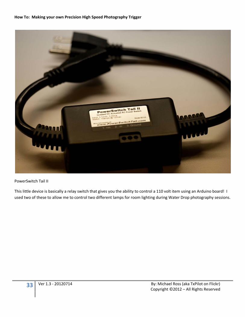
PowerSwitch Tail II
This little device is basically a relay switch that gives you the ability to control a 110 volt item using an Arduino board! I used two of these to allow me to control two different lamps for room lighting during Water Drop photography sessions.
How To: Making your own Precision High Speed Photography Trigger
34 Ver 1.3 - 20120714 By: Michael Ross (aka TxPilot on Flickr) Copyright ©2012 – All Rights Reserved
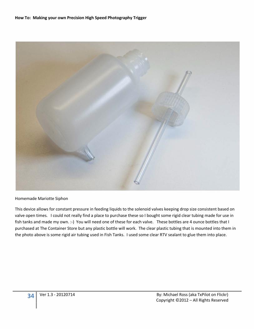
Homemade Mariotte Siphon
This device allows for constant pressure in feeding liquids to the solenoid valves keeping drop size consistent based on valve open times. I could not really find a place to purchase these so I bought some rigid clear tubing made for use in fish tanks and made my own. :-) You will need one of these for each valve. These bottles are 4 ounce bottles that I purchased at The Container Store but any plastic bottle will work. The clear plastic tubing that is mounted into them in the photo above is some rigid air tubing used in Fish Tanks. I used some clear RTV sealant to glue them into place.
How To: Making your own Precision High Speed Photography Trigger
35 Ver 1.3 - 20120714 By: Michael Ross (aka TxPilot on Flickr) Copyright ©2012 – All Rights Reserved
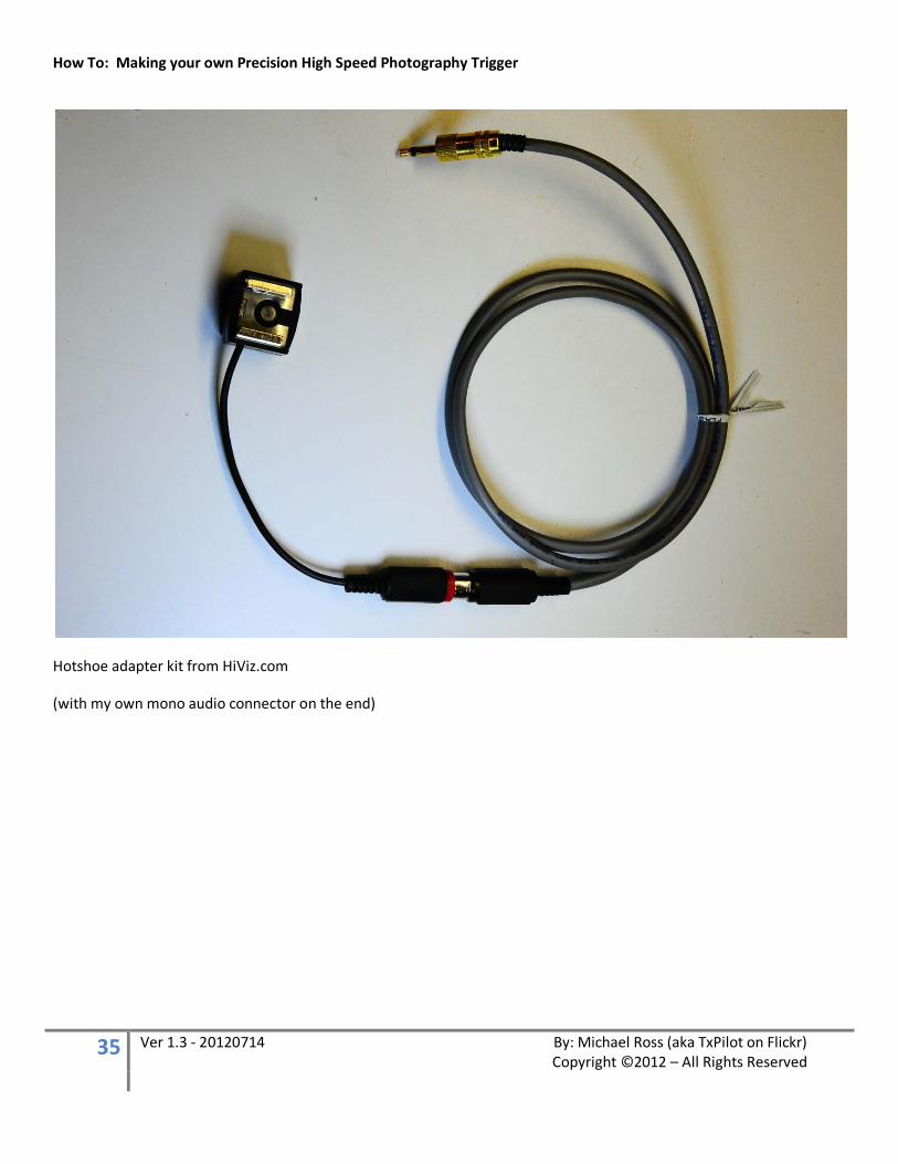
Hotshoe adapter kit from HiViz.com
(with my own mono audio connector on the end)
How To: Making your own Precision High Speed Photography Trigger
36 Ver 1.3 - 20120714 By: Michael Ross (aka TxPilot on Flickr) Copyright ©2012 – All Rights Reserved
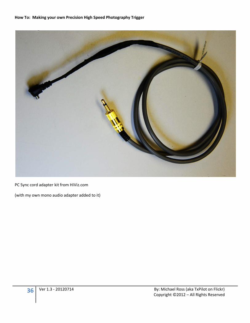
PC Sync cord adapter kit from HiViz.com
(with my own mono audio adapter added to it)
How To: Making your own Precision High Speed Photography Trigger
37 Ver 1.3 - 20120714 By: Michael Ross (aka TxPilot on Flickr) Copyright ©2012 – All Rights Reserved
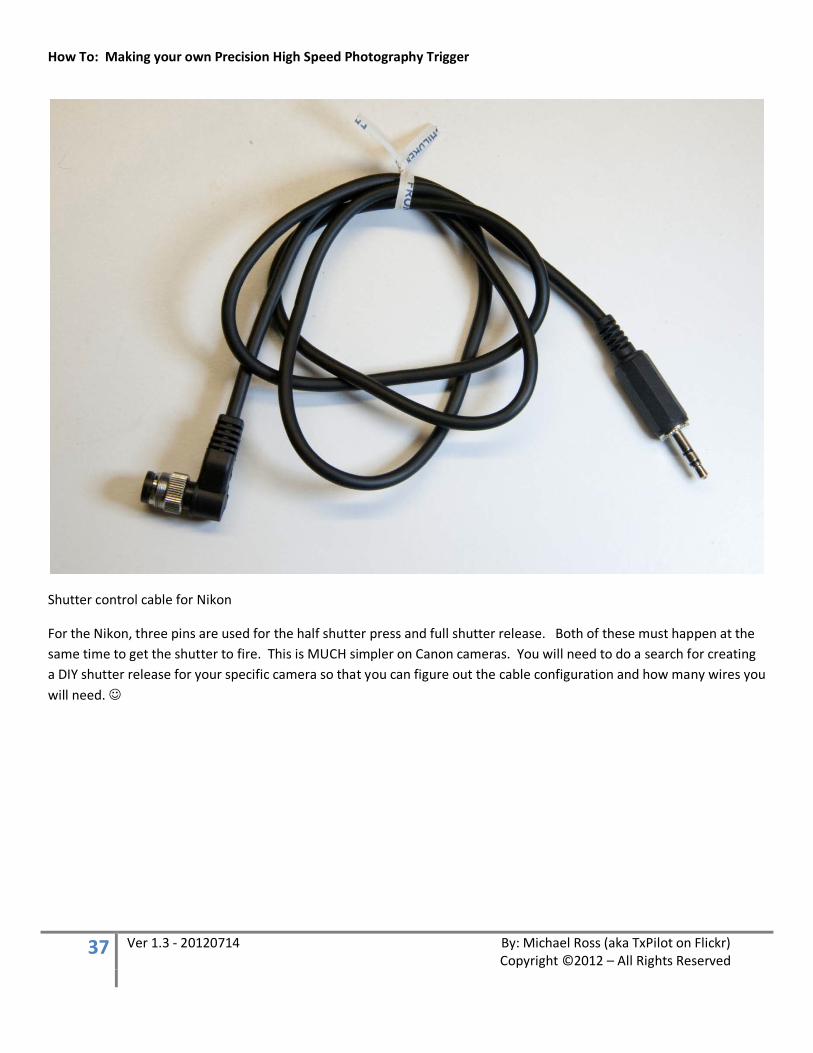
Shutter control cable for Nikon
For the Nikon, three pins are used for the half shutter press and full shutter release. Both of these must happen at the same time to get the shutter to fire. This is MUCH simpler on Canon cameras. You will need to do a search for creating a DIY shutter release for your specific camera so that you can figure out the cable configuration and how many wires you will need.
How To: Making your own Precision High Speed Photography Trigger
38 Ver 1.3 - 20120714 By: Michael Ross (aka TxPilot on Flickr) Copyright ©2012 – All Rights Reserved
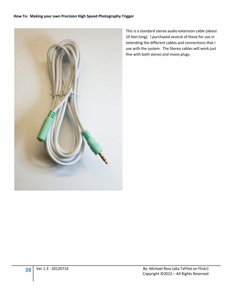
This is a standard stereo audio extension cable (about 10 feet long). I purchased several of these for use in extending the different cables and connections that I use with the system. The Stereo cables will work just fine with both stereo and mono plugs.
How To: Making your own Precision High Speed Photography Trigger
39 Ver 1.3 - 20120714 By: Michael Ross (aka TxPilot on Flickr) Copyright ©2012 – All Rights Reserved
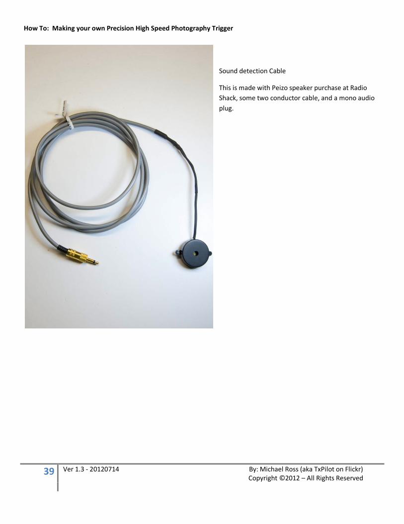
Sound detection Cable
This is made with Peizo speaker purchase at Radio Shack, some two conductor cable, and a mono audio plug.

How To: Making your own Precision High Speed Photography Trigger
40 Ver 1.3 - 20120714 By: Michael Ross (aka TxPilot on Flickr) Copyright ©2012 – All Rights Reserved
Remote Launch button and Switch
This was made with a small electronics project box, one push button switch and one SPST switch, some two conductor cable, and an “N” size power plug.
The SPST switch is used to put the unit in an endless mode as if you were holding the Launch button down continuously. Sometimes it takes a LOT of photos to get that ONE photo you are looking for. ;-)
How To: Making your own Precision High Speed Photography Trigger
41 Ver 1.3 - 20120714 By: Michael Ross (aka TxPilot on Flickr) Copyright ©2012 – All Rights Reserved
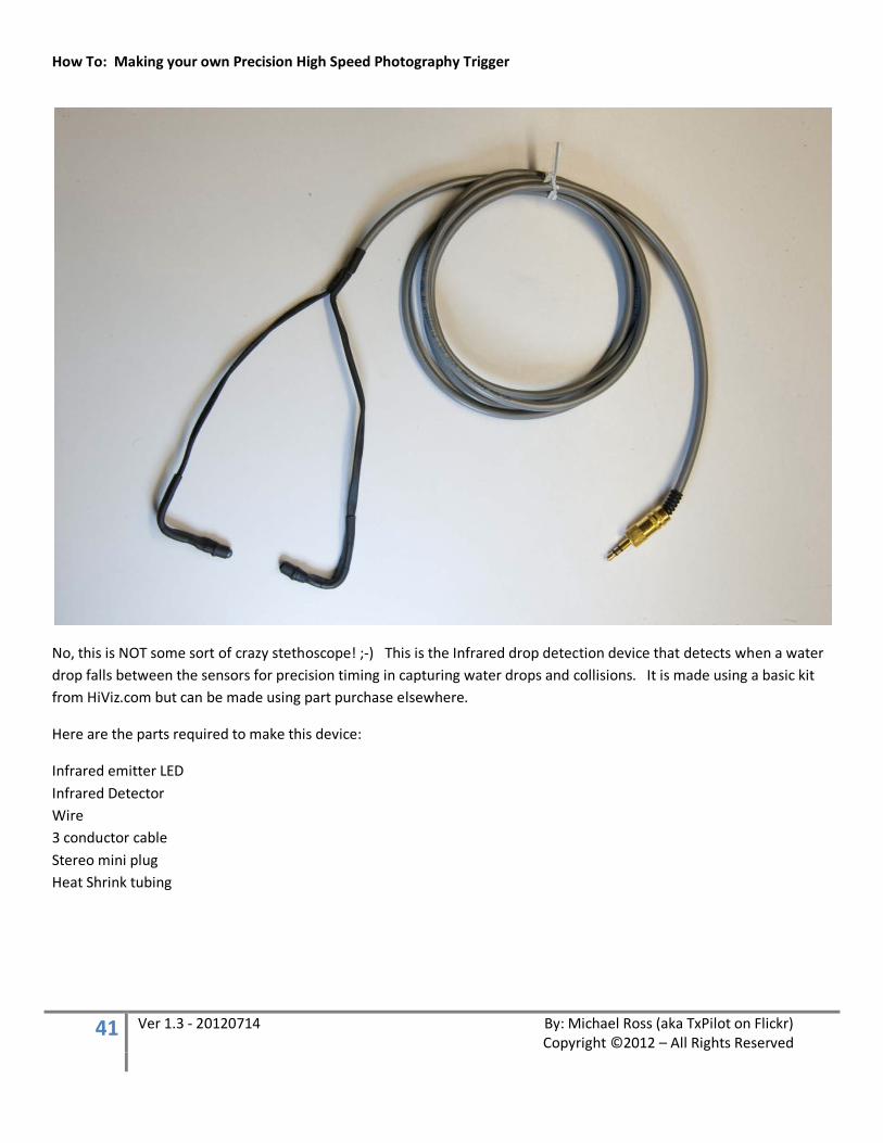
No, this is NOT some sort of crazy stethoscope! ;-) This is the Infrared drop detection device that detects when a water drop falls between the sensors for precision timing in capturing water drops and collisions. It is made using a basic kit from HiViz.com but can be made using part purchase elsewhere.
Here are the parts required to make this device:
Infrared emitter LED Infrared Detector Wire 3 conductor cable Stereo mini plug Heat Shrink tubing
How To: Making your own Precision High Speed Photography Trigger
42 Ver 1.3 - 20120714 By: Michael Ross (aka TxPilot on Flickr) Copyright ©2012 – All Rights Reserved
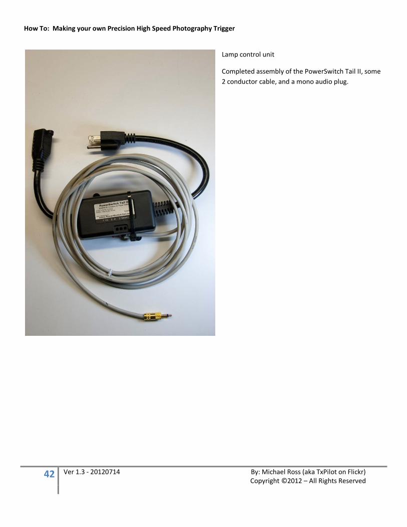
Lamp control unit
Completed assembly of the PowerSwitch Tail II, some 2 conductor cable, and a mono audio plug.
How To: Making your own Precision High Speed Photography Trigger
43 Ver 1.3 - 20120714 By: Michael Ross (aka TxPilot on Flickr) Copyright ©2012 – All Rights Reserved
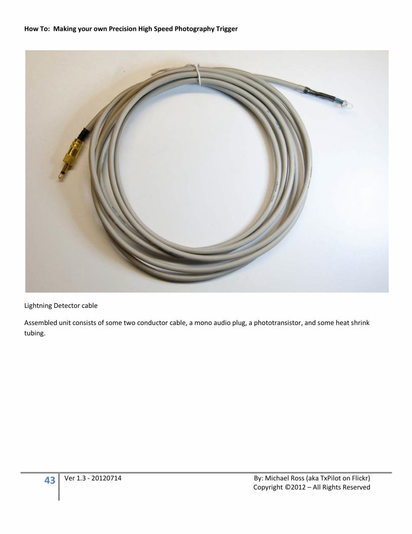
Lightning Detector cable
Assembled unit consists of some two conductor cable, a mono audio plug, a phototransistor, and some heat shrink tubing.
How To: Making your own Precision High Speed Photography Trigger
44 Ver 1.3 - 20120714 By: Michael Ross (aka TxPilot on Flickr) Copyright ©2012 – All Rights Reserved
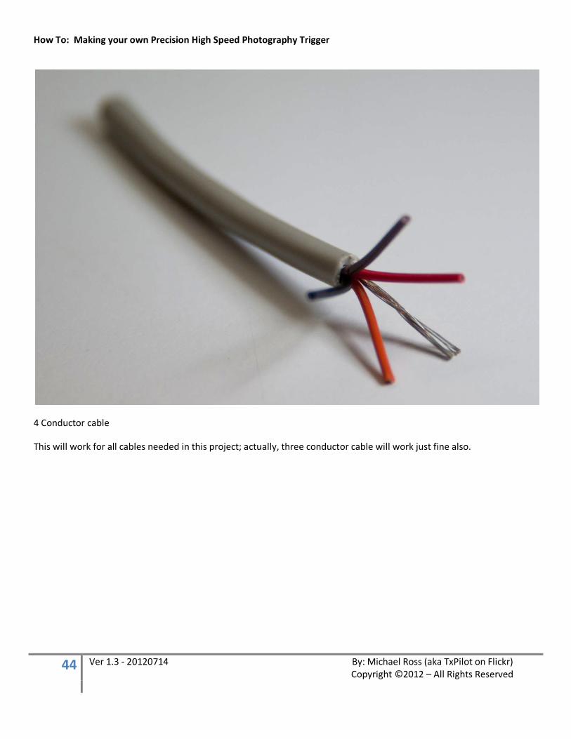
4 Conductor cable
This will work for all cables needed in this project; actually, three conductor cable will work just fine also.

How To: Making your own Precision High Speed Photography Trigger
45 Ver 1.3 - 20120714 By: Michael Ross (aka TxPilot on Flickr) Copyright ©2012 – All Rights Reserved
Stranded 20 or 22 gauge wire
Use plenty of different colors to help you keep track of things. Also, as a general “rule” of electronics, Red is used for positive power and Black is used for Negative or Ground. But that is certainly not a hard fast rule, just a good idea to follow to help identify things by standards.
How To: Making your own Precision High Speed Photography Trigger
46 Ver 1.3 - 20120714 By: Michael Ross (aka TxPilot on Flickr) Copyright ©2012 – All Rights Reserved
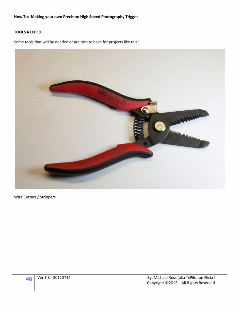
TOOLS NEEDED
Some tools that will be needed or are nice to have for projects like this!
Wire Cutters / Strippers
How To: Making your own Precision High Speed Photography Trigger
47 Ver 1.3 - 20120714 By: Michael Ross (aka TxPilot on Flickr) Copyright ©2012 – All Rights Reserved
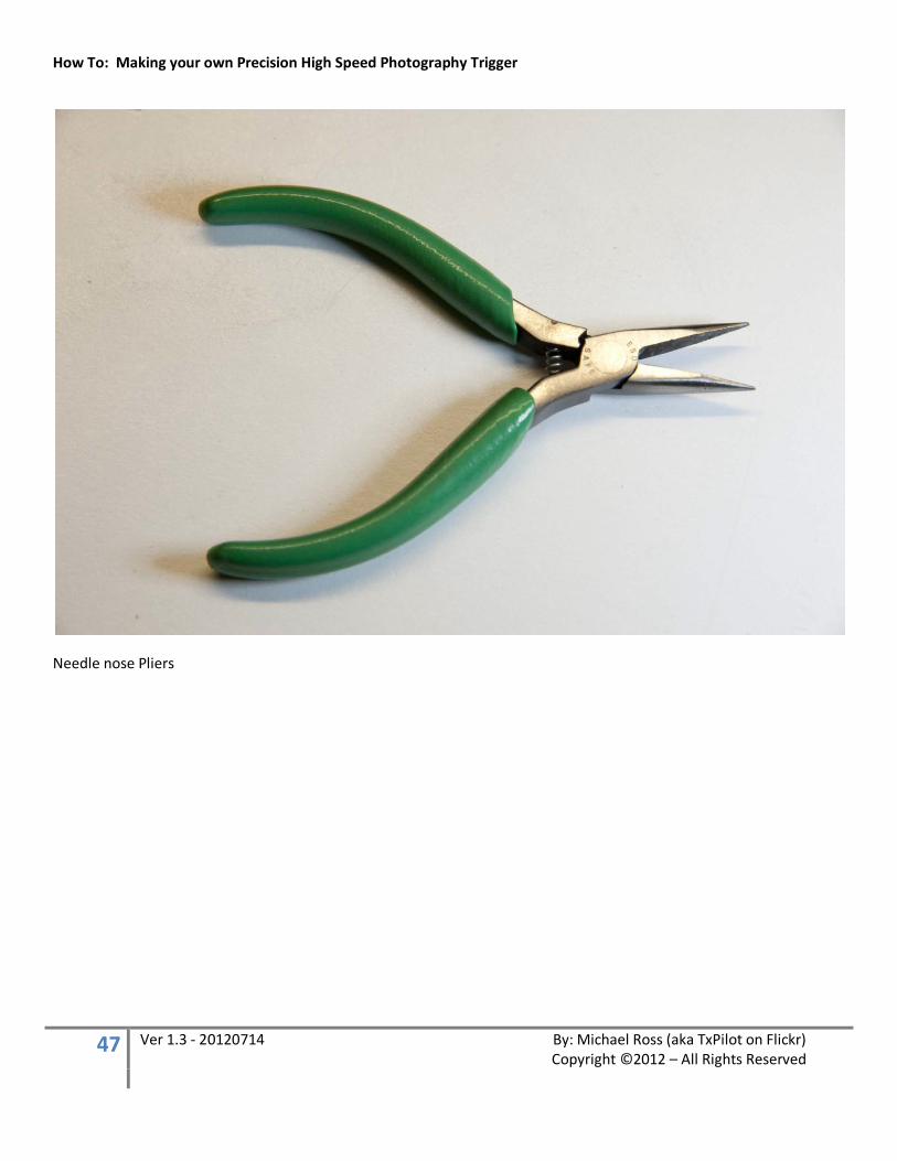
Needle nose Pliers
How To: Making your own Precision High Speed Photography Trigger
48 Ver 1.3 - 20120714 By: Michael Ross (aka TxPilot on Flickr) Copyright ©2012 – All Rights Reserved
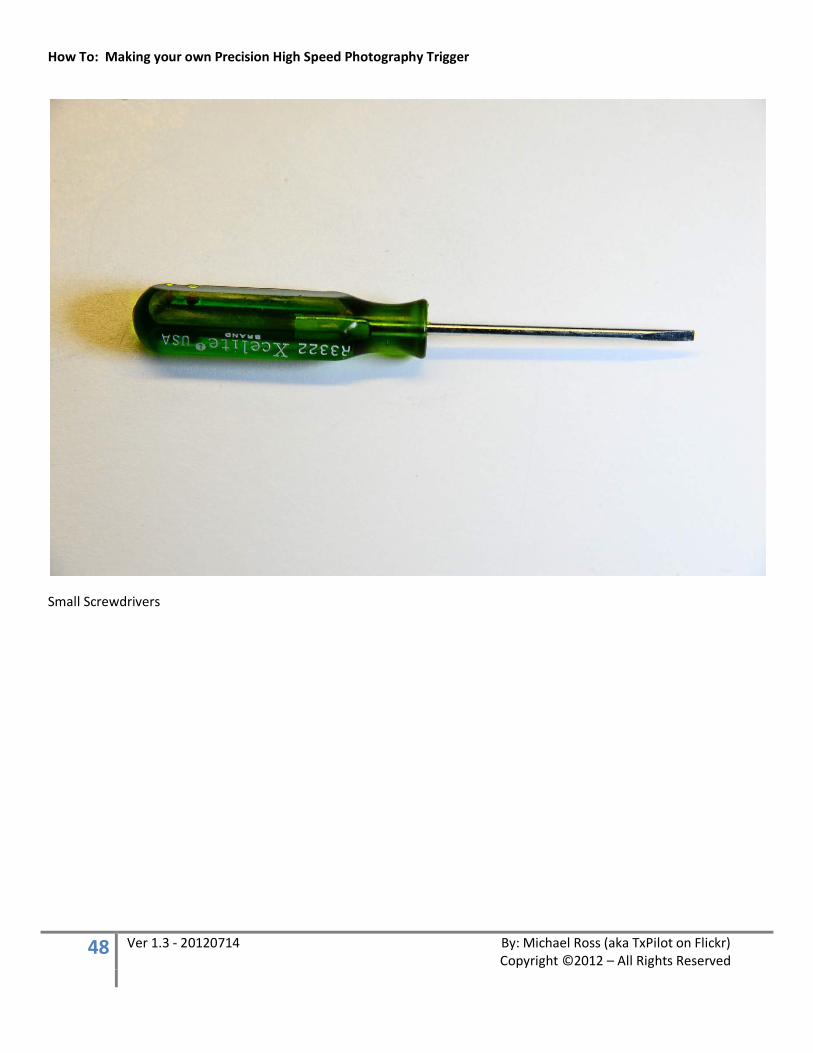
Small Screwdrivers
How To: Making your own Precision High Speed Photography Trigger
49 Ver 1.3 - 20120714 By: Michael Ross (aka TxPilot on Flickr) Copyright ©2012 – All Rights Reserved
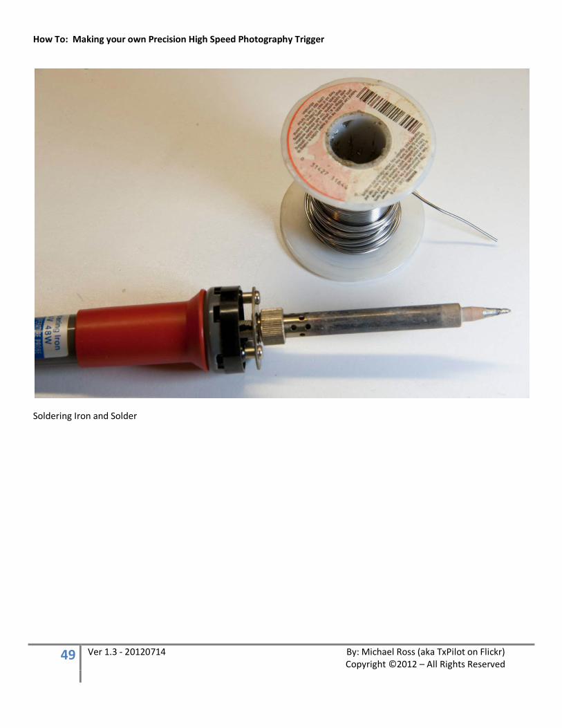
Soldering Iron and Solder

How To: Making your own Precision High Speed Photography Trigger
50 Ver 1.3 - 20120714 By: Michael Ross (aka TxPilot on Flickr) Copyright ©2012 – All Rights Reserved
Diagonal cutters

How To: Making your own Precision High Speed Photography Trigger
51 Ver 1.3 - 20120714 By: Michael Ross (aka TxPilot on Flickr) Copyright ©2012 – All Rights Reserved
Vernier Calipers
Once you get used to using these, you won’t be able to work without them! ;-)
How To: Making your own Precision High Speed Photography Trigger
52 Ver 1.3 - 20120714 By: Michael Ross (aka TxPilot on Flickr) Copyright ©2012 – All Rights Reserved
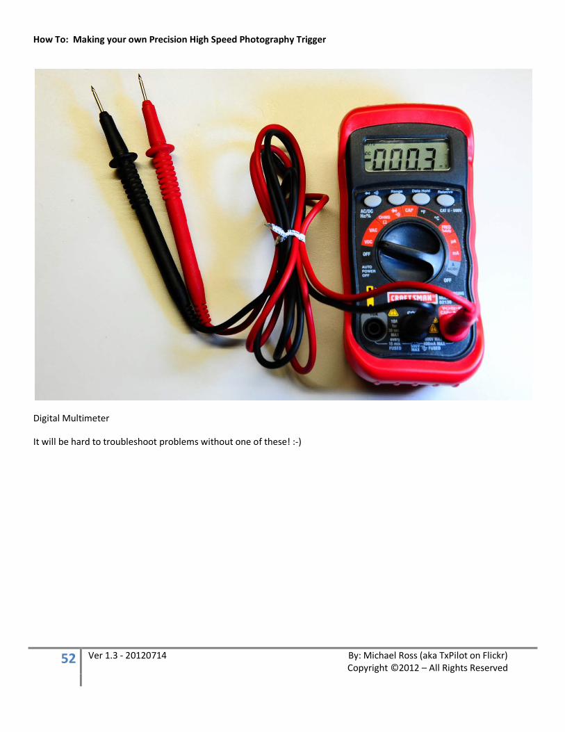
Digital Multimeter
It will be hard to troubleshoot problems without one of these! :-)

How To: Making your own Precision High Speed Photography Trigger
53 Ver 1.3 - 20120714 By: Michael Ross (aka TxPilot on Flickr) Copyright ©2012 – All Rights Reserved
A WORD ON SWITCHES
Before we get going too deep into this, I wanted to talk about the different types of switches that are used in this project. There are SOOOOOO many different types of switches out there that it can get confusing on exactly what to purchase for this project. On top of that, I am finding out that the same term in relation to switches can mean different things in different parts of the world! So that certainly doesn’t help matters!
There are only three types of switches that are being used in this project. Even though you see that I have used three different types of momentary push button switches, they are still all the same when it comes to how they work. There are two connections on the switch and when the button is pressed, the switch is turned on until it is released then it turns off on its own. From a technical standpoint, this is referred to as a “Normally Closed, Momentary Push Button Switch” and some designators would say that it is an OFF (ON) switch showing that it is normally off, then on when pressed. Those are easy enough.
What may get confusing are the toggle switches that are used in this project. There are two different types that are used so we will go over each one.
First is the SPST (Single Pole Single Throw) Switch
The switch above is a SPST switch that is considered an OFF-ON switch since it only has two connections on it. The Blue switch in the photo to the right is the same type of switch but it has three connections (ON-ON). Both of these switches have two physical positions and Both of these switches can be used in the way if you only connect two wires to them. These type of switches are used for the ON/OFF, Update/Arm, Infrared/Sound, Remote Launch constant ON, and Single/Multi Flash switches.
The Black toggle switch in the photo to the right is a SPDT switch. It has three physical positions (ON-OFF-ON). This switch is used for the Intervalometer-Off-Lightning detector switch in this project.
How To: Making your own Precision High Speed Photography Trigger
54 Ver 1.3 - 20120714 By: Michael Ross (aka TxPilot on Flickr) Copyright ©2012 – All Rights Reserved
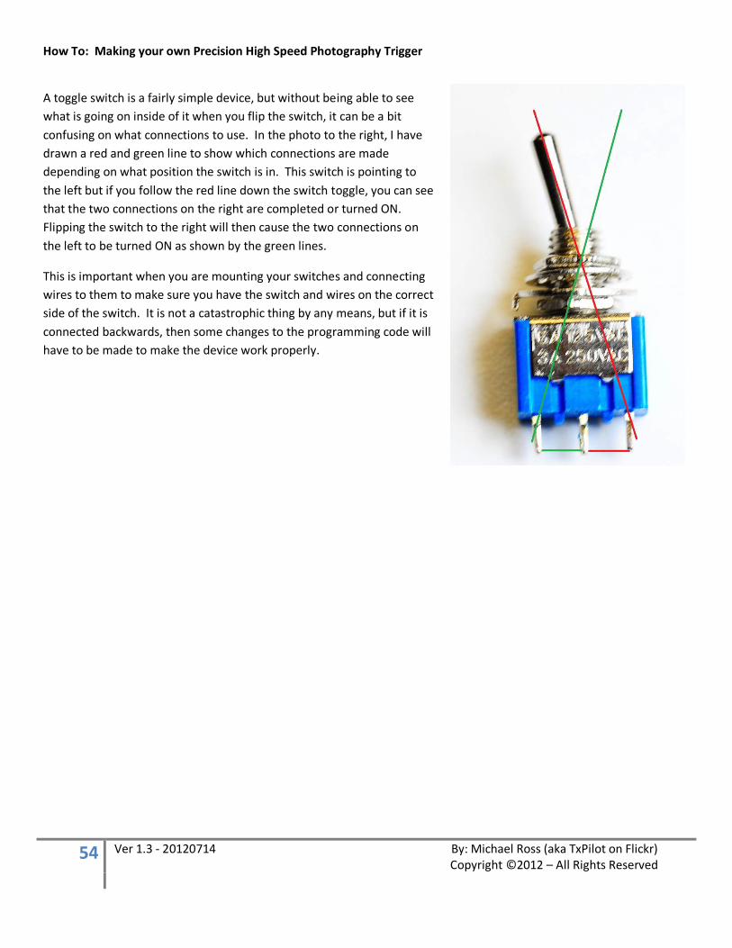
A toggle switch is a fairly simple device, but without being able to see what is going on inside of it when you flip the switch, it can be a bit confusing on what connections to use. In the photo to the right, I have drawn a red and green line to show which connections are made depending on what position the switch is in. This switch is pointing to the left but if you follow the red line down the switch toggle, you can see that the two connections on the right are completed or turned ON. Flipping the switch to the right will then cause the two connections on the left to be turned ON as shown by the green lines.
This is important when you are mounting your switches and connecting wires to them to make sure you have the switch and wires on the correct side of the switch. It is not a catastrophic thing by any means, but if it is connected backwards, then some changes to the programming code will have to be made to make the device work properly.
How To: Making your own Precision High Speed Photography Trigger
55 Ver 1.3 - 20120714 By: Michael Ross (aka TxPilot on Flickr) Copyright ©2012 – All Rights Reserved
GETTING STARTED
Okay... Before you decide to take this project on for yourself, here are some general notes to help make some decisions on things. First off, there are some DIY skills and tools that will be required to complete this project. Soldering tools and skills are a must and also a drill and Dremel Tool are pretty much a must have along with some general DIY skills such as being able to mark and drill holes for switches and mounting the LCD display. If you are not at least a little comfortable with being able to handle those things or are afraid to dive into it if this is your first project like this, then it is probably not a project you want to take on. But even with that said, none of this is rocket science by any means and you certainly don't need to understand electronics to put this together! Anyone with some basic DIY skills can do this. So if you think you are close, then go ahead and dive in and don't be afraid to ask questions along the way. There are plenty of people, including myself, that are more than happy to help someone along in a project like this. As far as the electronics go I will explain a little basics about what each component does in the operation of this unit, but I am not going to get into the detailed electronic theory behind it all.
Also, please keep this in mind. I am listing the parts out for the unit as I built it. You certainly don't have to take it as far as I did and you can make modifications on your own unit if you wish. For example, if you only want a single solenoid valve instead of 4, then by all means, only add the components for one. Same thing if you would like 16 of them instead! Ha! Nothing like making and shooting your own rain storm! ;-) There are several components that you can leave out if you just want a simple single valve water drop system. So don't be afraid to customize it to your needs.

How To: Making your own Precision High Speed Photography Trigger
56 Ver 1.3 - 20120714 By: Michael Ross (aka TxPilot on Flickr) Copyright ©2012 – All Rights Reserved
THE WIRING DIAGRAM
For the rest of this project, you will want to download and refer to the wiring diagram that was created for this tutorial. It is located at:
http://www.mrossphoto.com/PHSPT/PHSPT_Wiring_Diagram-12_Volt_Solenoids.png
Okay... so let's jump in! :-)
How To: Making your own Precision High Speed Photography Trigger
57 Ver 1.3 - 20120714 By: Michael Ross (aka TxPilot on Flickr) Copyright ©2012 – All Rights Reserved
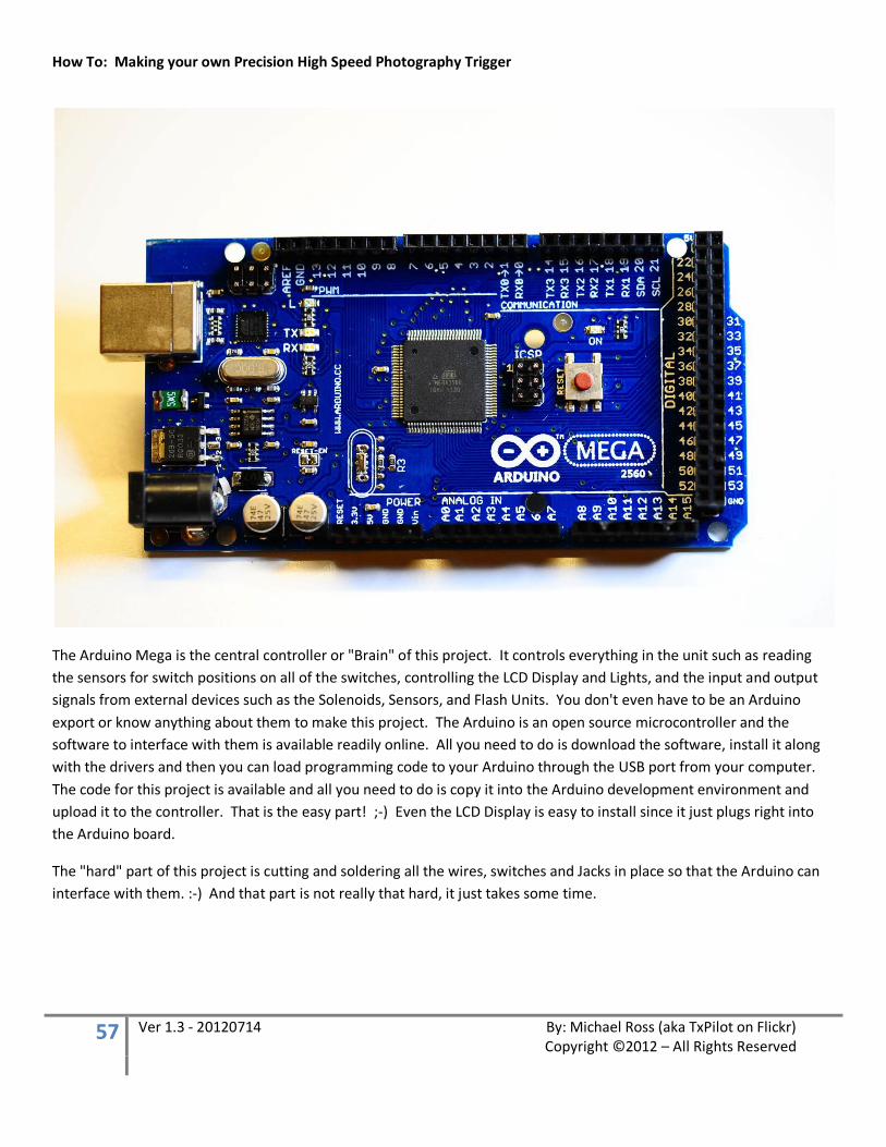
The Arduino Mega is the central controller or "Brain" of this project. It controls everything in the unit such as reading the sensors for switch positions on all of the switches, controlling the LCD Display and Lights, and the input and output signals from external devices such as the Solenoids, Sensors, and Flash Units. You don't even have to be an Arduino export or know anything about them to make this project. The Arduino is an open source microcontroller and the software to interface with them is available readily online. All you need to do is download the software, install it along with the drivers and then you can load programming code to your Arduino through the USB port from your computer. The code for this project is available and all you need to do is copy it into the Arduino development environment and upload it to the controller. That is the easy part! ;-) Even the LCD Display is easy to install since it just plugs right into the Arduino board.
The "hard" part of this project is cutting and soldering all the wires, switches and Jacks in place so that the Arduino can interface with them. :-) And that part is not really that hard, it just takes some time.

How To: Making your own Precision High Speed Photography Trigger
58 Ver 1.3 - 20120714 By: Michael Ross (aka TxPilot on Flickr) Copyright ©2012 – All Rights Reserved
A simple power circuit mounted in a small breadboard
I used breadboards to mount components into for the project for a few reasons. First of all, it is easy to place components and connections for testing since you don't have to do any soldering! Just plug the component in and plug the connections in and you are ready to go! This also makes it easy to make adjustments to the project if need be by changing components or even adding other functionality at a later date if needed. The down side to using breadboards is that the joints are not soldered and components can be knocked loose causing things to a bit nuts. Usually all you have to do is push them firmly back into their holes and you are good to go again. Since this unit won't be used in a portable setting that much, that should not be too much of an issue. However, if you are not familiar with how breadboards are laid out, then it will be a good thing to read up on them so you know the basics of how things are connected together on the inside of them. :-) The light blue lines in the photo above show how the holes are connected together inside the breadboard to give you an idea how things connect together when you push something into the holes.
Here are a few places to learn about breadboards and their layout.
http://en.wikipedia.org/wiki/Breadboard http://www.kpsec.freeuk.com/breadb.htm
How To: Making your own Precision High Speed Photography Trigger
59 Ver 1.3 - 20120714 By: Michael Ross (aka TxPilot on Flickr) Copyright ©2012 – All Rights Reserved
LAYING THINGS OUT
Once you have all of your parts gathered for the project, you can start putting them all together. I usually start a project like this by getting an idea about how I want things to be laid out. I start first with the layout of the interface and switches on the outside, and then with the layout on the inside. Keep in mind that you want to keep things in some order to make them easy to get to.
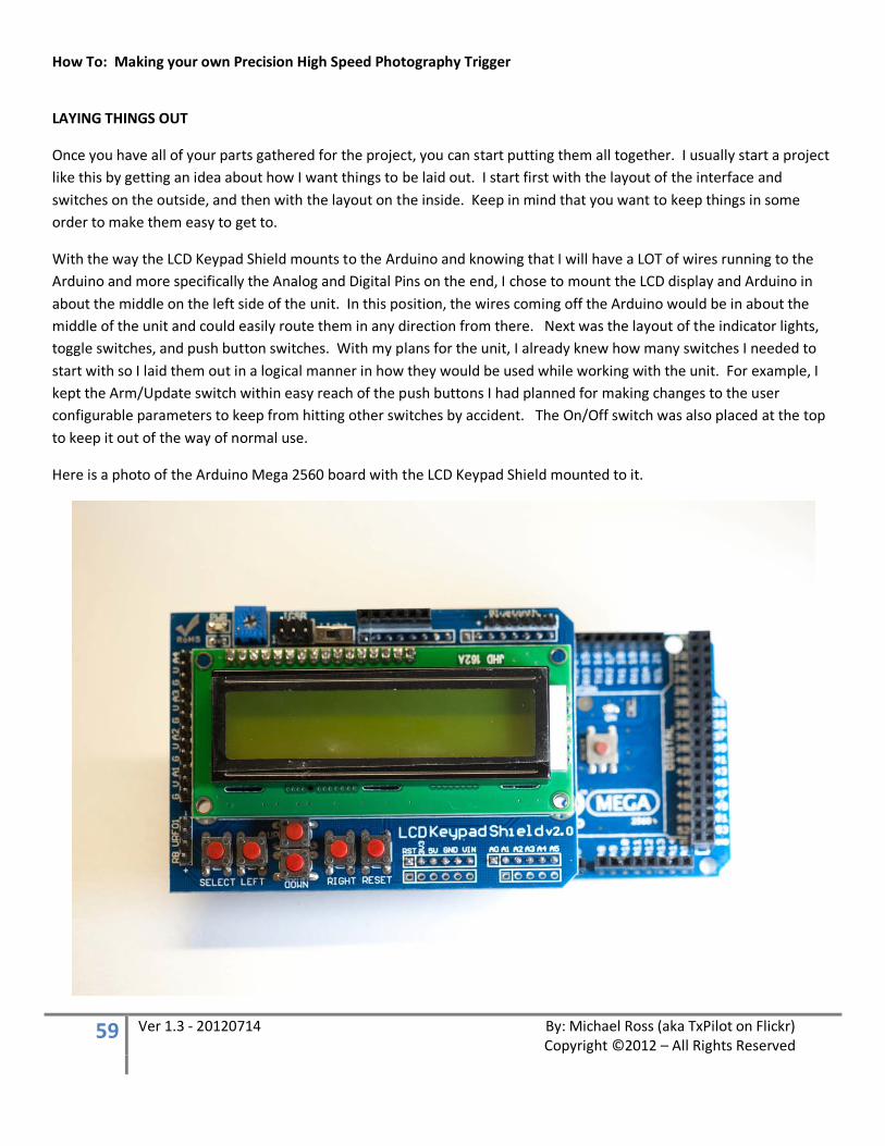
With the way the LCD Keypad Shield mounts to the Arduino and knowing that I will have a LOT of wires running to the Arduino and more specifically the Analog and Digital Pins on the end, I chose to mount the LCD display and Arduino in about the middle on the left side of the unit. In this position, the wires coming off the Arduino would be in about the middle of the unit and could easily route them in any direction from there. Next was the layout of the indicator lights, toggle switches, and push button switches. With my plans for the unit, I already knew how many switches I needed to start with so I laid them out in a logical manner in how they would be used while working with the unit. For example, I kept the Arm/Update switch within easy reach of the push buttons I had planned for making changes to the user configurable parameters to keep from hitting other switches by accident. The On/Off switch was also placed at the top to keep it out of the way of normal use.
Here is a photo of the Arduino Mega 2560 board with the LCD Keypad Shield mounted to it.

How To: Making your own Precision High Speed Photography Trigger
60 Ver 1.3 - 20120714 By: Michael Ross (aka TxPilot on Flickr) Copyright ©2012 – All Rights Reserved
Now, in the photo of the Arduino board with the LCD Keypad Shield above, you will notice that it has its own buttons for use in selecting values. These buttons however are not mounted in a way that would make it easy to mount inside a project box so I elected to just the use the display and add my own push button switches for the user interface. You could use a different LCD display if you wanted to, but you will probably have to make some adjustments to the programming code if you do. It is up to you. I would have chosen a different display type if I didn’t already have this one.
The dimensions for this specific LCD display are 2.79” x .95” so that is how big we need our mounting hole to be so the LCD screen will fit snugly through the top of the enclosure.
How To: Making your own Precision High Speed Photography Trigger
61 Ver 1.3 - 20120714 By: Michael Ross (aka TxPilot on Flickr) Copyright ©2012 – All Rights Reserved
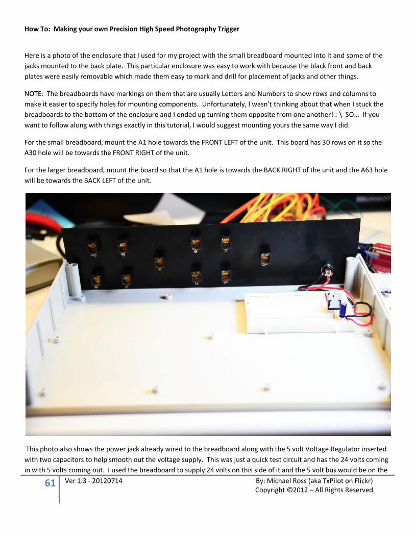
Here is a photo of the enclosure that I used for my project with the small breadboard mounted into it and some of the jacks mounted to the back plate. This particular enclosure was easy to work with because the black front and back plates were easily removable which made them easy to mark and drill for placement of jacks and other things.
NOTE: The breadboards have markings on them that are usually Letters and Numbers to show rows and columns to make it easier to specify holes for mounting components. Unfortunately, I wasn’t thinking about that when I stuck the breadboards to the bottom of the enclosure and I ended up turning them opposite from one another! :-\ SO… If you want to follow along with things exactly in this tutorial, I would suggest mounting yours the same way I did.
For the small breadboard, mount the A1 hole towards the FRONT LEFT of the unit. This board has 30 rows on it so the A30 hole will be towards the FRONT RIGHT of the unit.
For the larger breadboard, mount the board so that the A1 hole is towards the BACK RIGHT of the unit and the A63 hole will be towards the BACK LEFT of the unit.
This photo also shows the power jack already wired to the breadboard along with the 5 volt Voltage Regulator inserted with two capacitors to help smooth out the voltage supply. This was just a quick test circuit and has the 24 volts coming in with 5 volts coming out. I used the breadboard to supply 24 volts on this side of it and the 5 volt bus would be on the
How To: Making your own Precision High Speed Photography Trigger
62 Ver 1.3 - 20120714 By: Michael Ross (aka TxPilot on Flickr) Copyright ©2012 – All Rights Reserved
other side. Jumper wires were used to complete the connections. There will be more details on this circuit a little bit later in this tutorial. Note: The heatsink was also not mounted to the voltage regulator yet. And I found out VERY quickly that it REALLY needed one! Ouch! HOT!!!!
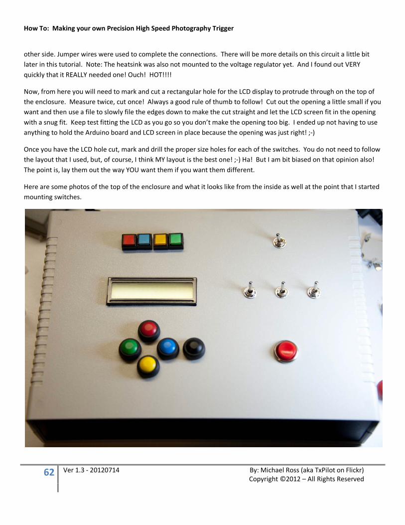
Now, from here you will need to mark and cut a rectangular hole for the LCD display to protrude through on the top of the enclosure. Measure twice, cut once! Always a good rule of thumb to follow! Cut out the opening a little small if you want and then use a file to slowly file the edges down to make the cut straight and let the LCD screen fit in the opening with a snug fit. Keep test fitting the LCD as you go so you don’t make the opening too big. I ended up not having to use anything to hold the Arduino board and LCD screen in place because the opening was just right! ;-)
Once you have the LCD hole cut, mark and drill the proper size holes for each of the switches. You do not need to follow the layout that I used, but, of course, I think MY layout is the best one! ;-) Ha! But I am bit biased on that opinion also! The point is, lay them out the way YOU want them if you want them different.
Here are some photos of the top of the enclosure and what it looks like from the inside as well at the point that I started mounting switches.
How To: Making your own Precision High Speed Photography Trigger
63 Ver 1.3 - 20120714 By: Michael Ross (aka TxPilot on Flickr) Copyright ©2012 – All Rights Reserved
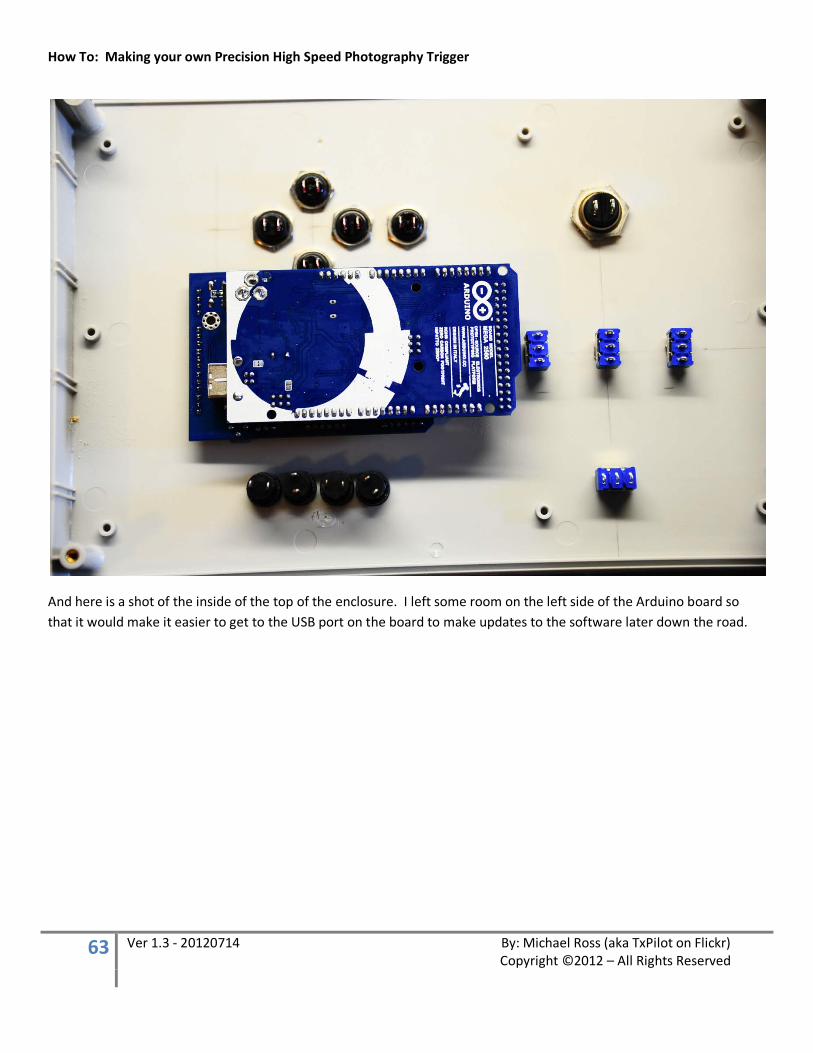
And here is a shot of the inside of the top of the enclosure. I left some room on the left side of the Arduino board so that it would make it easier to get to the USB port on the board to make updates to the software later down the road.
How To: Making your own Precision High Speed Photography Trigger
64 Ver 1.3 - 20120714 By: Michael Ross (aka TxPilot on Flickr) Copyright ©2012 – All Rights Reserved
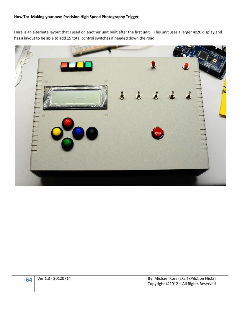
Here is an alternate layout that I used on another unit built after the first unit. This unit uses a larger 4x20 display and has a layout to be able to add 15 total control switches if needed down the road.
How To: Making your own Precision High Speed Photography Trigger
65 Ver 1.3 - 20120714 By: Michael Ross (aka TxPilot on Flickr) Copyright ©2012 – All Rights Reserved
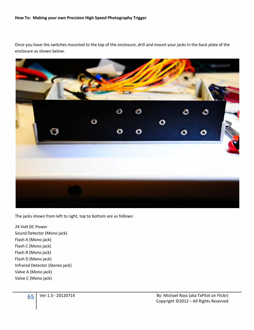
Once you have the switches mounted to the top of the enclosure, drill and mount your jacks in the back plate of the enclosure as shown below.
The jacks shown from left to right, top to bottom are as follows:
24 Volt DC Power Sound Detector (Mono jack) Flash A (Mono jack) Flash C (Mono jack) Flash B (Mono jack) Flash D (Mono jack) Infrared Detector (Stereo jack) Valve A (Mono jack) Valve C (Mono jack)
How To: Making your own Precision High Speed Photography Trigger
66 Ver 1.3 - 20120714 By: Michael Ross (aka TxPilot on Flickr) Copyright ©2012 – All Rights Reserved
Valve B (Mono jack) Valve D(Mono jack)
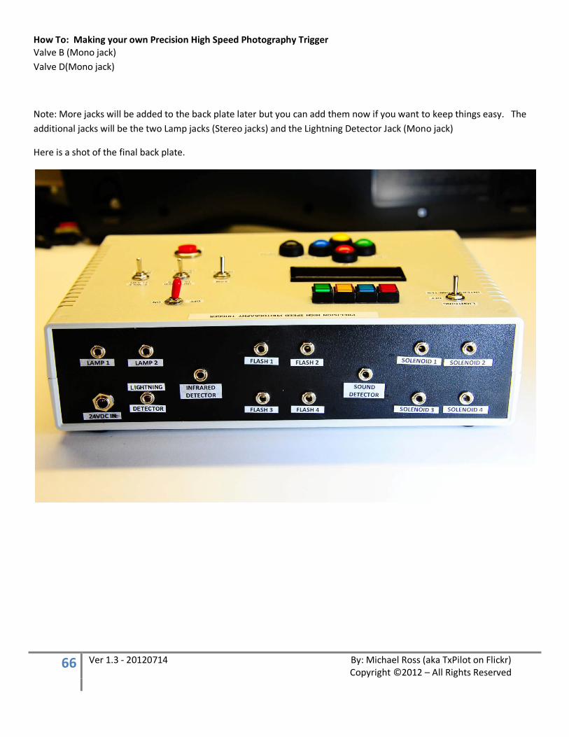
Note: More jacks will be added to the back plate later but you can add them now if you want to keep things easy. The additional jacks will be the two Lamp jacks (Stereo jacks) and the Lightning Detector Jack (Mono jack)
Here is a shot of the final back plate.
How To: Making your own Precision High Speed Photography Trigger
67 Ver 1.3 - 20120714 By: Michael Ross (aka TxPilot on Flickr) Copyright ©2012 – All Rights Reserved
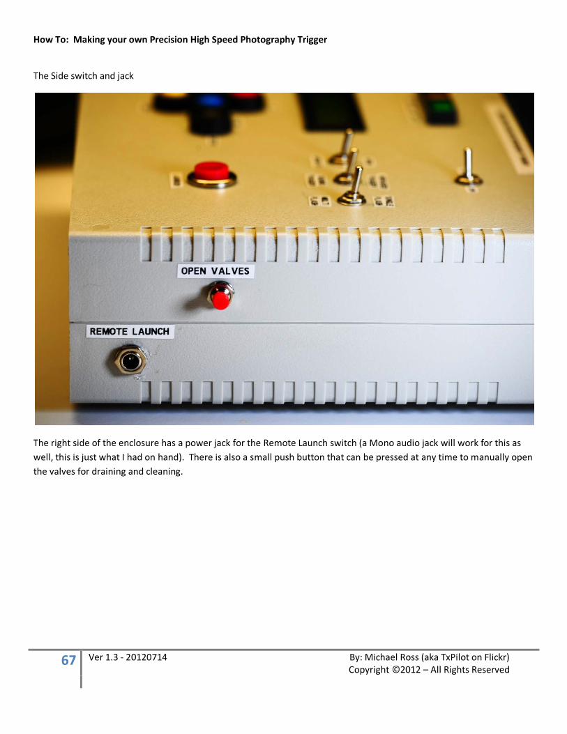
The Side switch and jack
The right side of the enclosure has a power jack for the Remote Launch switch (a Mono audio jack will work for this as well, this is just what I had on hand). There is also a small push button that can be pressed at any time to manually open the valves for draining and cleaning.
How To: Making your own Precision High Speed Photography Trigger
68 Ver 1.3 - 20120714 By: Michael Ross (aka TxPilot on Flickr) Copyright ©2012 – All Rights Reserved
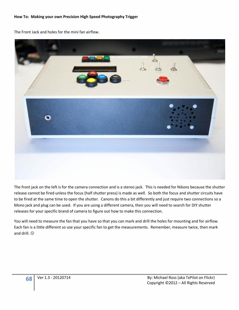
The Front Jack and holes for the mini fan airflow.
The front jack on the left is for the camera connection and is a stereo jack. This is needed for Nikons because the shutter release cannot be fired unless the focus (half shutter press) is made as well. So both the focus and shutter circuits have to be fired at the same time to open the shutter. Canons do this a bit differently and just require two connections so a Mono jack and plug can be used. If you are using a different camera, then you will need to search for DIY shutter releases for your specific brand of camera to figure out how to make this connection.
You will need to measure the fan that you have so that you can mark and drill the holes for mounting and for airflow. Each fan is a little different so use your specific fan to get the measurements. Remember, measure twice, then mark and drill.
How To: Making your own Precision High Speed Photography Trigger
69 Ver 1.3 - 20120714 By: Michael Ross (aka TxPilot on Flickr) Copyright ©2012 – All Rights Reserved
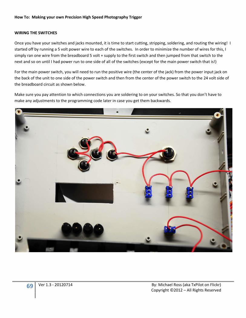
WIRING THE SWITCHES
Once you have your switches and jacks mounted, it is time to start cutting, stripping, soldering, and routing the wiring! I started off by running a 5 volt power wire to each of the switches. In order to minimize the number of wires for this, I simply ran one wire from the breadboard 5 volt + supply to the first switch and then jumped from that switch to the next and so on until I had power run to one side of all of the switches (except for the main power switch that is!)
For the main power switch, you will need to run the positive wire (the center of the jack) from the power input jack on the back of the unit to one side of the power switch and then from the center of the power switch to the 24 volt side of the breadboard circuit as shown below.
Make sure you pay attention to which connections you are soldering to on your switches. So that you don’t have to make any adjustments to the programming code later in case you get them backwards.
How To: Making your own Precision High Speed Photography Trigger
70 Ver 1.3 - 20120714 By: Michael Ross (aka TxPilot on Flickr) Copyright ©2012 – All Rights Reserved
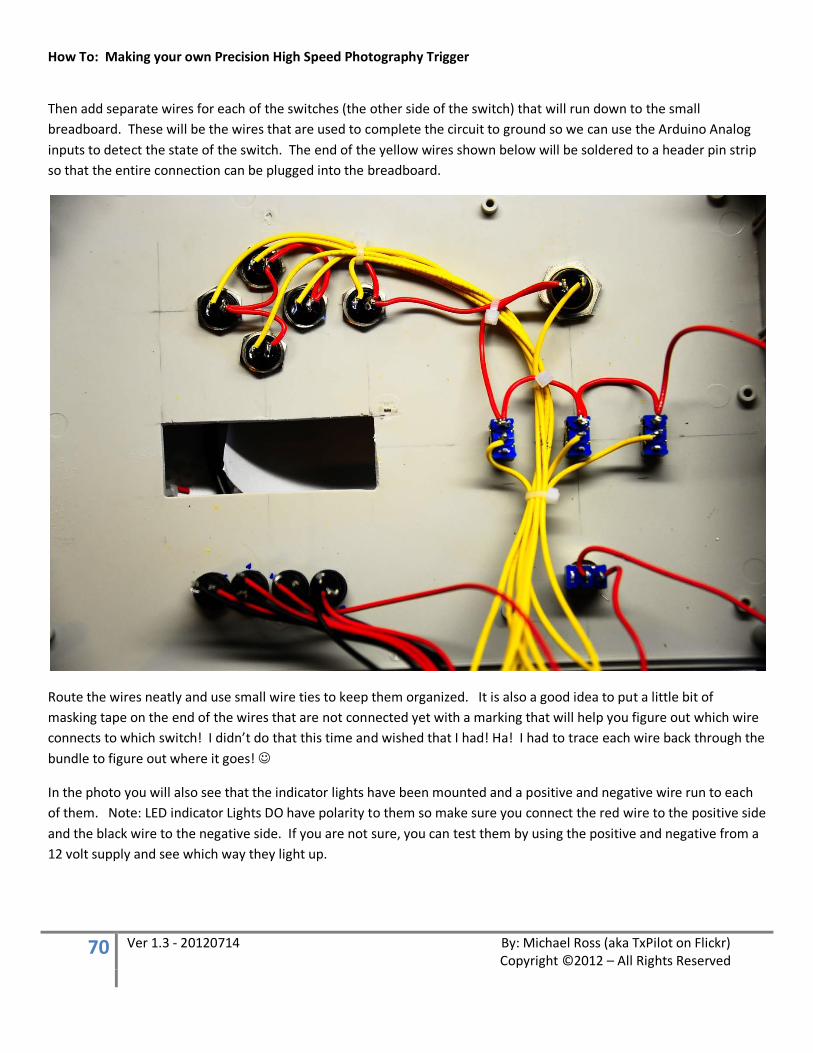
Then add separate wires for each of the switches (the other side of the switch) that will run down to the small breadboard. These will be the wires that are used to complete the circuit to ground so we can use the Arduino Analog inputs to detect the state of the switch. The end of the yellow wires shown below will be soldered to a header pin strip so that the entire connection can be plugged into the breadboard.
Route the wires neatly and use small wire ties to keep them organized. It is also a good idea to put a little bit of masking tape on the end of the wires that are not connected yet with a marking that will help you figure out which wire connects to which switch! I didn’t do that this time and wished that I had! Ha! I had to trace each wire back through the bundle to figure out where it goes!
In the photo you will also see that the indicator lights have been mounted and a positive and negative wire run to each of them. Note: LED indicator Lights DO have polarity to them so make sure you connect the red wire to the positive side and the black wire to the negative side. If you are not sure, you can test them by using the positive and negative from a 12 volt supply and see which way they light up.
How To: Making your own Precision High Speed Photography Trigger
71 Ver 1.3 - 20120714 By: Michael Ross (aka TxPilot on Flickr) Copyright ©2012 – All Rights Reserved
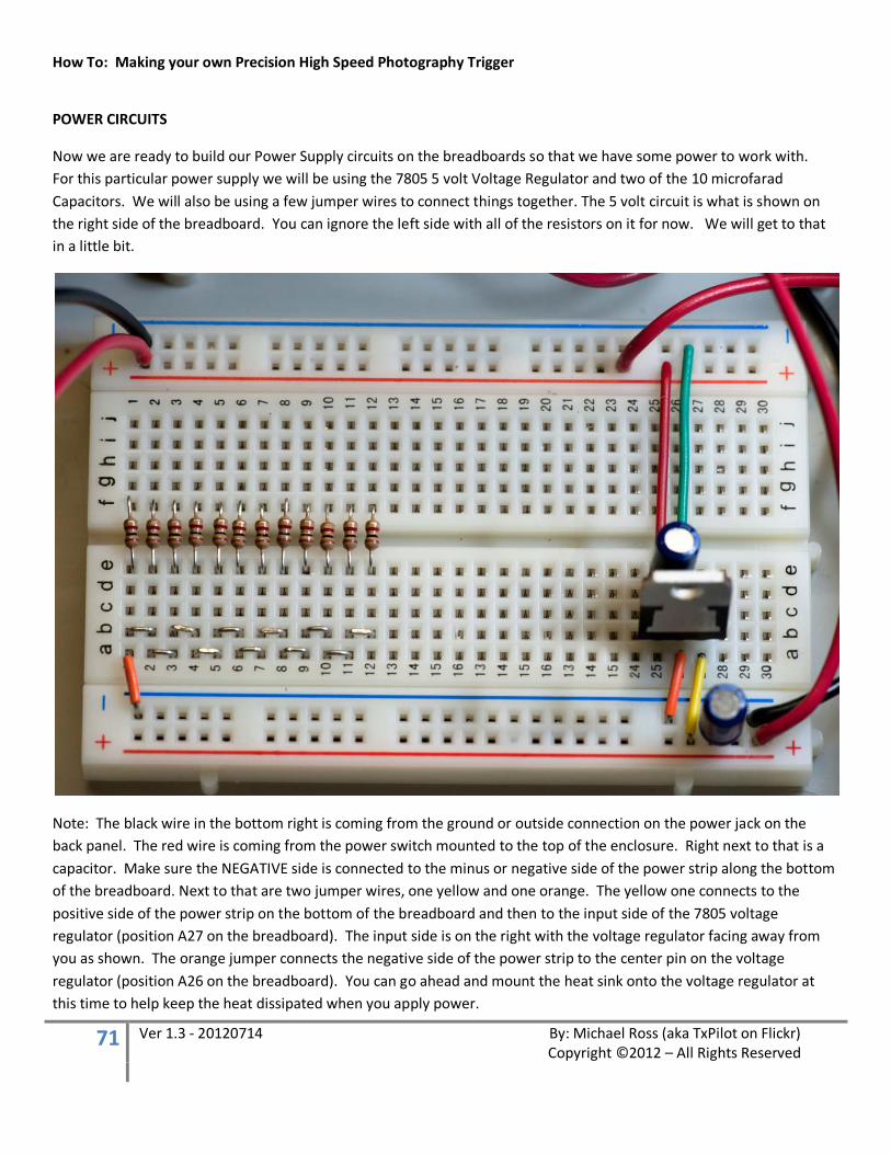
POWER CIRCUITS
Now we are ready to build our Power Supply circuits on the breadboards so that we have some power to work with. For this particular power supply we will be using the 7805 5 volt Voltage Regulator and two of the 10 microfarad Capacitors. We will also be using a few jumper wires to connect things together. The 5 volt circuit is what is shown on the right side of the breadboard. You can ignore the left side with all of the resistors on it for now. We will get to that in a little bit.
Note: The black wire in the bottom right is coming from the ground or outside connection on the power jack on the back panel. The red wire is coming from the power switch mounted to the top of the enclosure. Right next to that is a capacitor. Make sure the NEGATIVE side is connected to the minus or negative side of the power strip along the bottom of the breadboard. Next to that are two jumper wires, one yellow and one orange. The yellow one connects to the positive side of the power strip on the bottom of the breadboard and then to the input side of the 7805 voltage regulator (position A27 on the breadboard). The input side is on the right with the voltage regulator facing away from you as shown. The orange jumper connects the negative side of the power strip to the center pin on the voltage regulator (position A26 on the breadboard). You can go ahead and mount the heat sink onto the voltage regulator at this time to help keep the heat dissipated when you apply power.
How To: Making your own Precision High Speed Photography Trigger
72 Ver 1.3 - 20120714 By: Michael Ross (aka TxPilot on Flickr) Copyright ©2012 – All Rights Reserved
The voltage regulator itself should be mounted into positions B27, B26, and B25 with the front of the voltage regulator facing towards the back of the unit. Now, on the other side (the front) of the voltage regulator, you will be inserting another 10 microfarad capacitor into position D26 and D25 with the negative lead going into D26. Again, make sure the NEGATIVE side of the capacitor is connected to the same row that the center pin of the voltage regulator is in. The Positive side of the Capacitor should be connected to same row as the pin on the left (looking at the back side like this) of the voltage regulator. Then use two more jumper wires to connect the positive (left) pin of the voltage regulator (Position E25 on the breadboard) to the positive (+) power strip on the far side of the breadboard and the negative (center) pin (position E26 on the breadboard) to the negative (-) row on the power strip. The far side power strip will be the 5 volt power strip, and the power strip on the closest side will be a 24 volt power strip. Double check your connections and the positive and negative sides of the capacitors before apply any power from the external power supply.
The larger red wire that you see connected at the top right of the photo is the power wire that was run to all the switches on the top of the enclosure. Make sure it is connected to the 5 volt positive side as shown.
Note: To connect wires like this to a breadboard, I usually strip about a quarter inch of insulation off the end of the wire and then “Tin” it or coat the wire with a thin layer of solder. This helps to thicken it up a bit so it will hold in the breadboard better.
Okay… now on to the resistors and jumpers on the left side of the breadboard!
Each of the resistors is the same value. They are 1K Ohm (Brown, Black, Red, Gold) 1/8th watt resistors. I only show 12 of them in this photo but go ahead and insert 15 of them even though I ended up not using 4 of them. ;-) They will be there for later use in case we need to add anything. Notice that they are mounted across the center line on the breadboard in positions E1 through E15 and the other side of the resistors will be mounted in positions F1 through F15.
Note: I always cut the leads on the resistors down so that they fit into the board without sticking up off the board. This will keep them from possibly rubbing up against one another and causing a short circuit.
You will also notice some small jumpers on this side of the resistors the effectively connect all of them together. Then on the far left, there is a small orange jumper wire that connects the last one to the ground or negative (-) side of the power strip.
Don’t worry about the red and black wires that you see in the upper left of the photo, we will get to those later.
How To: Making your own Precision High Speed Photography Trigger
73 Ver 1.3 - 20120714 By: Michael Ross (aka TxPilot on Flickr) Copyright ©2012 – All Rights Reserved
WIRING THE ARDUINO BOARD
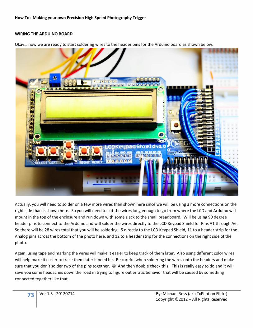
Okay… now we are ready to start soldering wires to the header pins for the Arduino board as shown below.
Actually, you will need to solder on a few more wires than shown here since we will be using 3 more connections on the right side than is shown here. So you will need to cut the wires long enough to go from where the LCD and Arduino will mount in the top of the enclosure and run down with some slack to the small breadboard. Will be using 90 degree header pins to connect to the Arduino and will solder the wires directly to the LCD Keypad Shield for Pins A1 through A6. So there will be 28 wires total that you will be soldering. 5 directly to the LCD Keypad Shield, 11 to a header strip for the Analog pins across the bottom of the photo here, and 12 to a header strip for the connections on the right side of the photo.
Again, using tape and marking the wires will make it easier to keep track of them later. Also using different color wires will help make it easier to trace them later if need be. Be careful when soldering the wires onto the headers and make sure that you don’t solder two of the pins together. And then double check this! This is really easy to do and it will save you some headaches down the road in trying to figure out erratic behavior that will be caused by something connected together like that.
How To: Making your own Precision High Speed Photography Trigger
74 Ver 1.3 - 20120714 By: Michael Ross (aka TxPilot on Flickr) Copyright ©2012 – All Rights Reserved
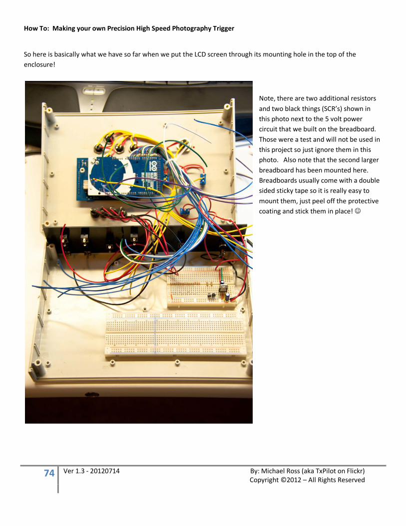
So here is basically what we have so far when we put the LCD screen through its mounting hole in the top of the enclosure!
Note, there are two additional resistors and two black things (SCR’s) shown in this photo next to the 5 volt power circuit that we built on the breadboard. Those were a test and will not be used in this project so just ignore them in this photo. Also note that the second larger breadboard has been mounted here. Breadboards usually come with a double sided sticky tape so it is really easy to mount them, just peel off the protective coating and stick them in place!

How To: Making your own Precision High Speed Photography Trigger
75 Ver 1.3 - 20120714 By: Michael Ross (aka TxPilot on Flickr) Copyright ©2012 – All Rights Reserved
Now… if the rest of your work area does not look like the photo below, then you are doing it wrong! So go back and start again to try and make a bigger mess! Ha! (Just Kidding! )
How To: Making your own Precision High Speed Photography Trigger
76 Ver 1.3 - 20120714 By: Michael Ross (aka TxPilot on Flickr) Copyright ©2012 – All Rights Reserved
WIRING THE BACK PANEL
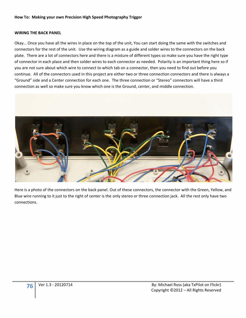
Okay… Once you have all the wires in place on the top of the unit, You can start doing the same with the switches and connectors for the rest of the unit. Use the wiring diagram as a guide and solder wires to the connectors on the back plate. There are a lot of connectors here and there is a mixture of different types so make sure you have the right type of connector in each place and then solder wires to each connector as needed. Polarity is an important thing here so if you are not sure about which wire to connect to which tab on a connector, then you need to find out before you continue. All of the connectors used in this project are either two or three connection connectors and there is always a “Ground” side and a Center connection for each one. The three connection or “Stereo” connectors will have a third connection as well so make sure you know which one is the Ground, center, and middle connection.
Here is a photo of the connectors on the back panel. Out of these connectors, the connector with the Green, Yellow, and Blue wire running to it just to the right of center is the only stereo or three connection jack. All the rest only have two connections.
How To: Making your own Precision High Speed Photography Trigger
77 Ver 1.3 - 20120714 By: Michael Ross (aka TxPilot on Flickr) Copyright ©2012 – All Rights Reserved
WIRING THE FRONT PANEL
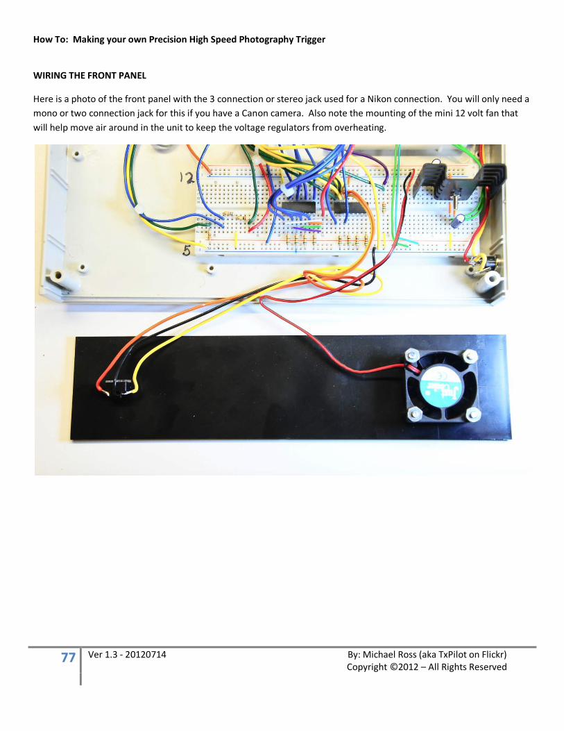
Here is a photo of the front panel with the 3 connection or stereo jack used for a Nikon connection. You will only need a mono or two connection jack for this if you have a Canon camera. Also note the mounting of the mini 12 volt fan that will help move air around in the unit to keep the voltage regulators from overheating.
How To: Making your own Precision High Speed Photography Trigger
78 Ver 1.3 - 20120714 By: Michael Ross (aka TxPilot on Flickr) Copyright ©2012 – All Rights Reserved
LAYING OUT THE REST OF THE CIRCUITS
Okay… It is time to start getting down to the details of finishing our circuits on the breadboards and then running the wiring to those circuits.
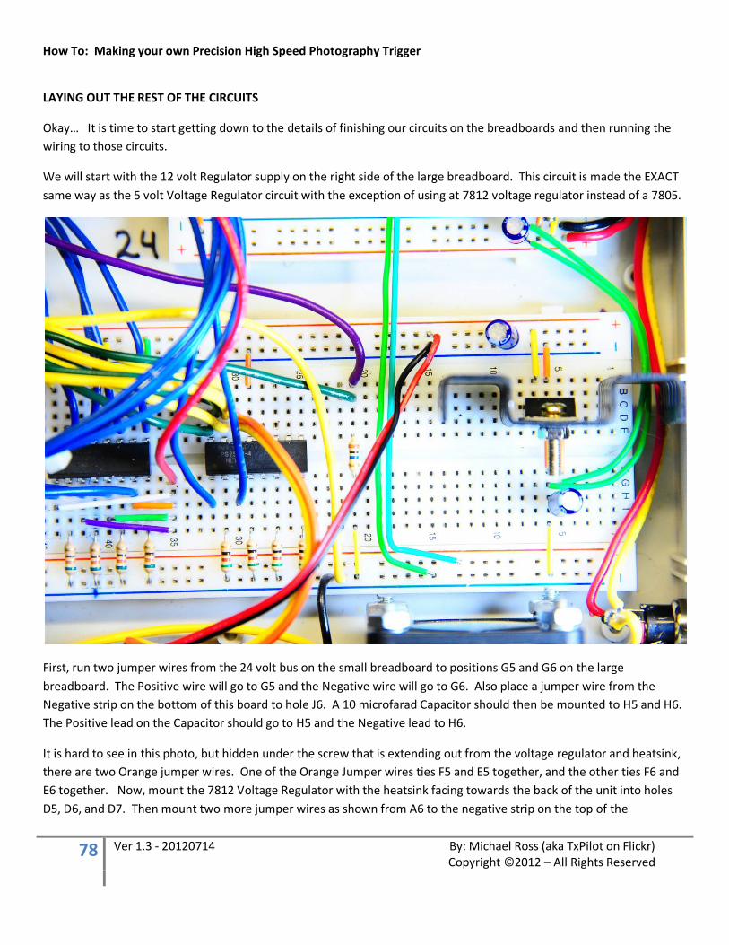
We will start with the 12 volt Regulator supply on the right side of the large breadboard. This circuit is made the EXACT same way as the 5 volt Voltage Regulator circuit with the exception of using at 7812 voltage regulator instead of a 7805.
First, run two jumper wires from the 24 volt bus on the small breadboard to positions G5 and G6 on the large breadboard. The Positive wire will go to G5 and the Negative wire will go to G6. Also place a jumper wire from the Negative strip on the bottom of this board to hole J6. A 10 microfarad Capacitor should then be mounted to H5 and H6. The Positive lead on the Capacitor should go to H5 and the Negative lead to H6.
It is hard to see in this photo, but hidden under the screw that is extending out from the voltage regulator and heatsink, there are two Orange jumper wires. One of the Orange Jumper wires ties F5 and E5 together, and the other ties F6 and E6 together. Now, mount the 7812 Voltage Regulator with the heatsink facing towards the back of the unit into holes D5, D6, and D7. Then mount two more jumper wires as shown from A6 to the negative strip on the top of the
How To: Making your own Precision High Speed Photography Trigger
79 Ver 1.3 - 20120714 By: Michael Ross (aka TxPilot on Flickr) Copyright ©2012 – All Rights Reserved
breadboard, and A7 to the Positive strip. An additional 10 microfarad capacitor will then be placed on the power strip next to these jumper wires. Make sure you get the negative and positive leads in the right position!
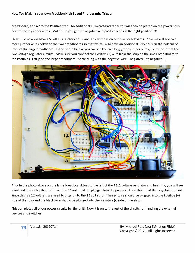
Okay… So now we have a 5 volt bus, a 24 volt bus, and a 12 volt bus on our two breadboards. Now we will add two more jumper wires between the two breadboards so that we will also have an additional 5 volt bus on the bottom or front of the large breadboard. In the photo below, you can see the two long green jumper wires just to the left of the two voltage regulator circuits. Make sure you connect the Positive (+) wire from the strip on the small breadboard to the Positive (+) strip on the large breadboard. Same thing with the negative wire… negative(-) to negative(-).
Also, in the photo above on the large breadboard, just to the left of the 7812 voltage regulator and heatsink, you will see a red and black wire that runs from the 12 volt mini fan plugged into the power strip on the top of the large breadboard. Since this is a 12 volt fan, we need to plug it into the 12 volt strip! The red wire should be plugged into the Positive (+) side of the strip and the black wire should be plugged into the Negative (-) side of the strip.
This completes all of our power circuits for the unit! Now it is on to the rest of the circuits for handling the external devices and switches!
How To: Making your own Precision High Speed Photography Trigger
80 Ver 1.3 - 20120714 By: Michael Ross (aka TxPilot on Flickr) Copyright ©2012 – All Rights Reserved
Here is a marked up photo showing which area of the breadboard has each circuit. We will start working our way from right to left since we already started with the 12 volt power circuit on the right side of the large breadboard.
I will be leaving out the connections that come from the Arduino board for now. We will be connecting those last.
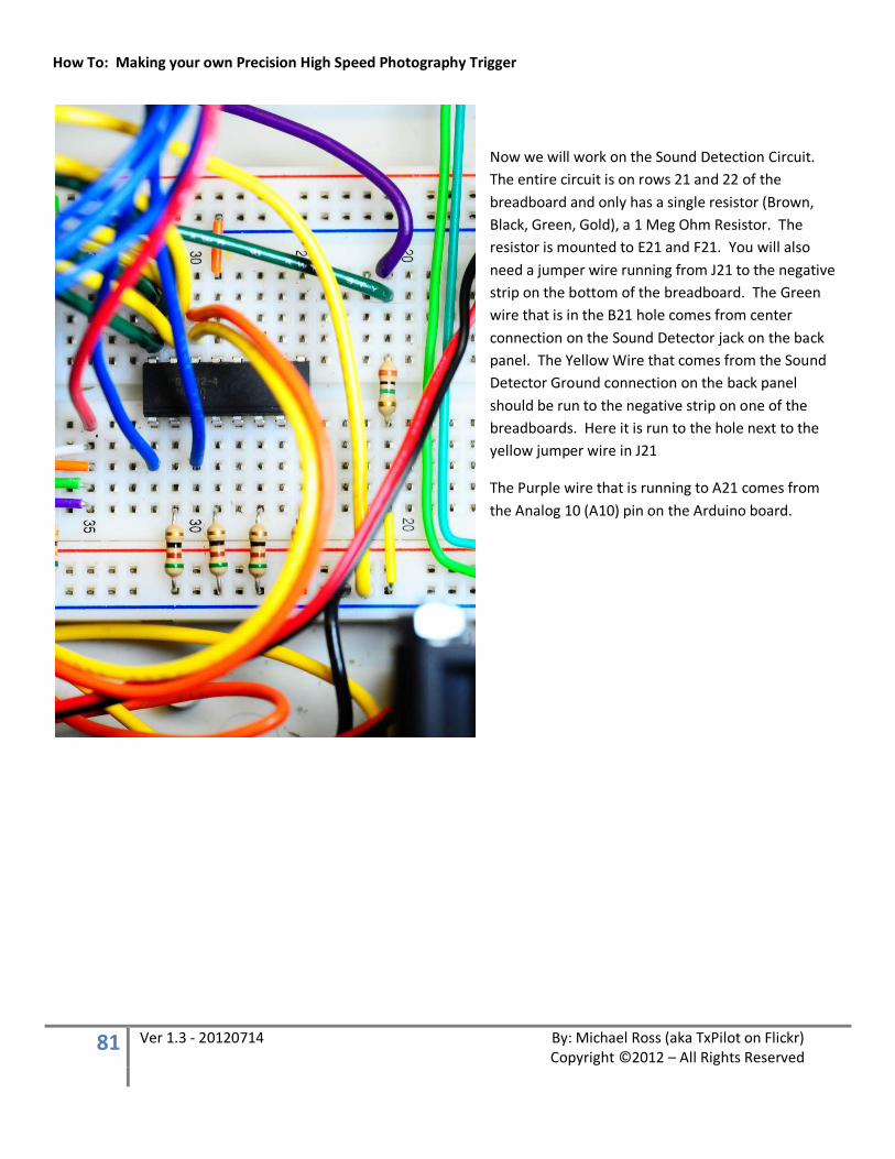
How To: Making your own Precision High Speed Photography Trigger
81 Ver 1.3 - 20120714 By: Michael Ross (aka TxPilot on Flickr) Copyright ©2012 – All Rights Reserved
Now we will work on the Sound Detection Circuit. The entire circuit is on rows 21 and 22 of the breadboard and only has a single resistor (Brown, Black, Green, Gold), a 1 Meg Ohm Resistor. The resistor is mounted to E21 and F21. You will also need a jumper wire running from J21 to the negative strip on the bottom of the breadboard. The Green wire that is in the B21 hole comes from center connection on the Sound Detector jack on the back panel. The Yellow Wire that comes from the Sound Detector Ground connection on the back panel should be run to the negative strip on one of the breadboards. Here it is run to the hole next to the yellow jumper wire in J21
The Purple wire that is running to A21 comes from the Analog 10 (A10) pin on the Arduino board.
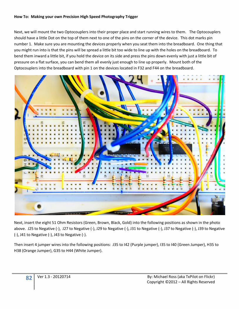
How To: Making your own Precision High Speed Photography Trigger
82 Ver 1.3 - 20120714 By: Michael Ross (aka TxPilot on Flickr) Copyright ©2012 – All Rights Reserved
Next, we will mount the two Optocouplers into their proper place and start running wires to them. The Optocouplers should have a little Dot on the top of them next to one of the pins on the corner of the device. This dot marks pin number 1. Make sure you are mounting the devices properly when you seat them into the breadboard. One thing that you might run into is that the pins will be spread a little bit too wide to line up with the holes on the breadboard. To bend them inward a little bit, if you hold the device on its side and press the pins down evenly with just a little bit of pressure on a flat surface, you can bend them all evenly just enough to line up properly. Mount both of the Optocouplers into the breadboard with pin 1 on the devices located in F32 and F44 on the breadboard.
Next, insert the eight 51 Ohm Resistors (Green, Brown, Black, Gold) into the following positions as shown in the photo above. J25 to Negative (-), J27 to Negative (-), J29 to Negative (-), J31 to Negative (-), J37 to Negative (-), J39 to Negative (-), J41 to Negative (-), J43 to Negative (-).
Then insert 4 jumper wires into the following positions: J35 to I42 (Purple jumper), I35 to I40 (Green Jumper), H35 to H38 (Orange Jumper), G35 to H44 (White Jumper).
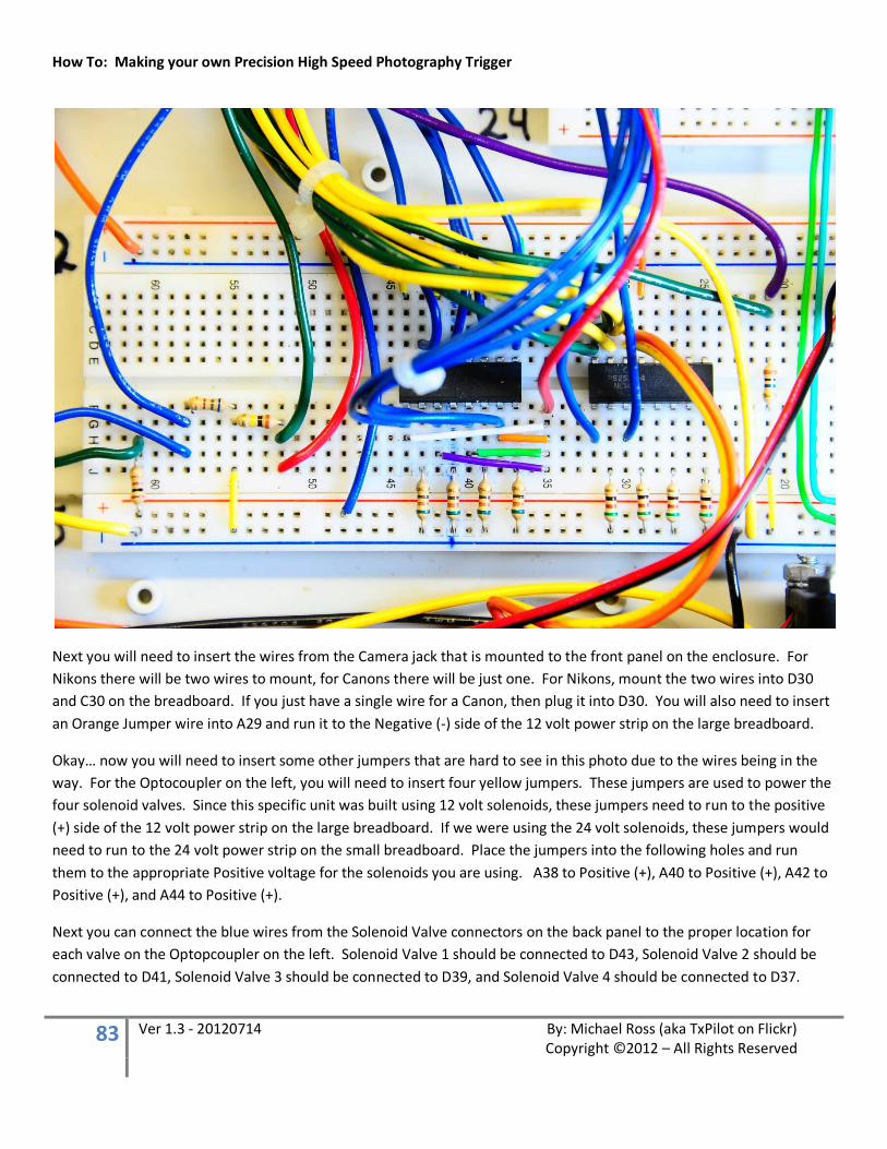
How To: Making your own Precision High Speed Photography Trigger
83 Ver 1.3 - 20120714 By: Michael Ross (aka TxPilot on Flickr) Copyright ©2012 – All Rights Reserved
Next you will need to insert the wires from the Camera jack that is mounted to the front panel on the enclosure. For Nikons there will be two wires to mount, for Canons there will be just one. For Nikons, mount the two wires into D30 and C30 on the breadboard. If you just have a single wire for a Canon, then plug it into D30. You will also need to insert an Orange Jumper wire into A29 and run it to the Negative (-) side of the 12 volt power strip on the large breadboard.
Okay… now you will need to insert some other jumpers that are hard to see in this photo due to the wires being in the way. For the Optocoupler on the left, you will need to insert four yellow jumpers. These jumpers are used to power the four solenoid valves. Since this specific unit was built using 12 volt solenoids, these jumpers need to run to the positive (+) side of the 12 volt power strip on the large breadboard. If we were using the 24 volt solenoids, these jumpers would need to run to the 24 volt power strip on the small breadboard. Place the jumpers into the following holes and run them to the appropriate Positive voltage for the solenoids you are using. A38 to Positive (+), A40 to Positive (+), A42 to Positive (+), and A44 to Positive (+).
Next you can connect the blue wires from the Solenoid Valve connectors on the back panel to the proper location for each valve on the Optopcoupler on the left. Solenoid Valve 1 should be connected to D43, Solenoid Valve 2 should be connected to D41, Solenoid Valve 3 should be connected to D39, and Solenoid Valve 4 should be connected to D37.

How To: Making your own Precision High Speed Photography Trigger
84 Ver 1.3 - 20120714 By: Michael Ross (aka TxPilot on Flickr) Copyright ©2012 – All Rights Reserved
Okay, just a few more wires to go for the Optocoupler area.
The orange wire that is connected to the negative (-) side of the 12 volt bus in the upper left corner of this photo is the ground or negative wire that runs to all four of the Solenoid Valve connectors. Plug this wire into the negative connection as shown.
The Red wire that is connected to F35 is the wire that is coming from the Manual Open Valves push button switch. This is so that you can push the button and it will apply power to the solenoid valves to open them for draining and cleaning.
The Green and Yellow wires that are connected to A32, B32, C32, D32, A31, B31, C31, and D31 are the wires that are coming from the four Flash connectors on the back panel. The Green wires are connected to the center part of the connectors and they need to connect to Row 32. The Yellow wires are connected to the outer part of the connectors and they need to be connected to Row 31. This connection will fire ALL flash units simultaneously!
We now only have 6 wires left for the Optocoupler circuits and those are the blue wires that connect from the Arduino Board. We will run those last.
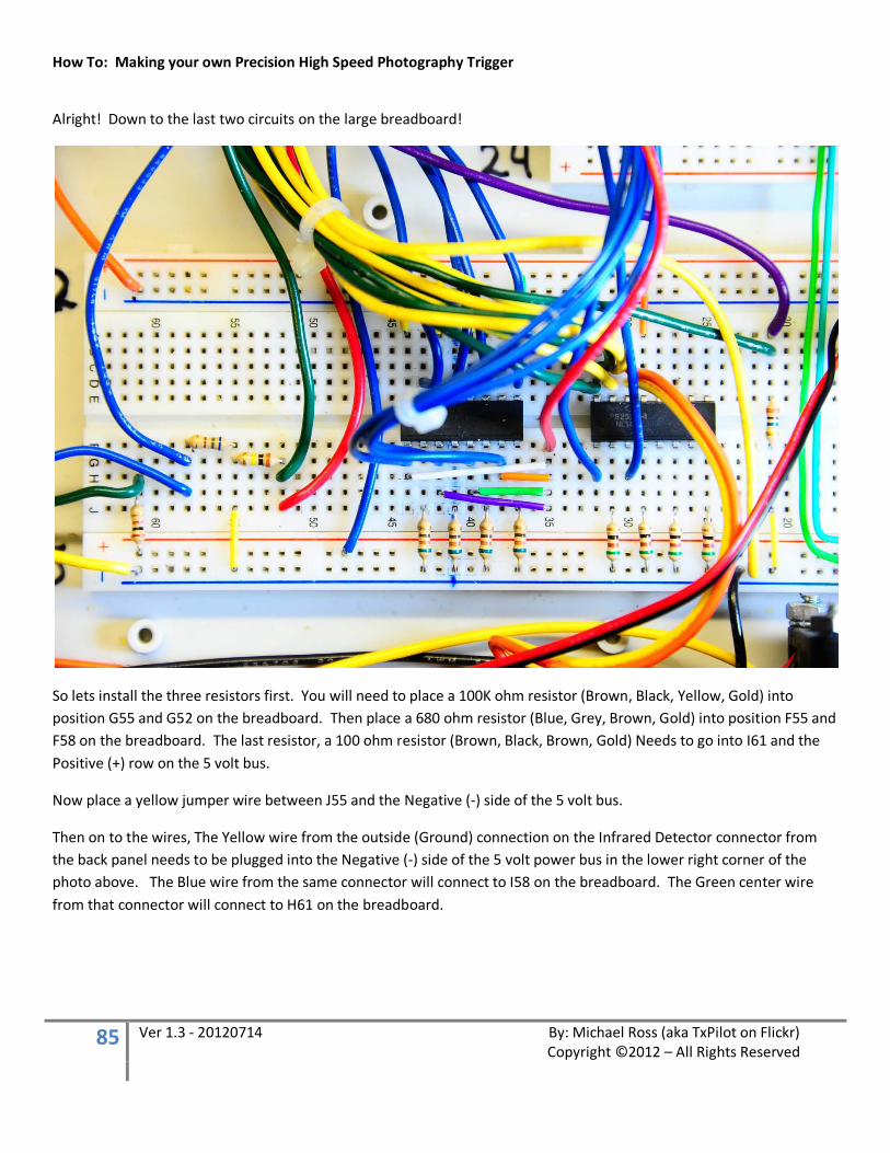
How To: Making your own Precision High Speed Photography Trigger
85 Ver 1.3 - 20120714 By: Michael Ross (aka TxPilot on Flickr) Copyright ©2012 – All Rights Reserved
Alright! Down to the last two circuits on the large breadboard!
So lets install the three resistors first. You will need to place a 100K ohm resistor (Brown, Black, Yellow, Gold) into position G55 and G52 on the breadboard. Then place a 680 ohm resistor (Blue, Grey, Brown, Gold) into position F55 and F58 on the breadboard. The last resistor, a 100 ohm resistor (Brown, Black, Brown, Gold) Needs to go into I61 and the Positive (+) row on the 5 volt bus.
Now place a yellow jumper wire between J55 and the Negative (-) side of the 5 volt bus.
Then on to the wires, The Yellow wire from the outside (Ground) connection on the Infrared Detector connector from the back panel needs to be plugged into the Negative (-) side of the 5 volt power bus in the lower right corner of the photo above. The Blue wire from the same connector will connect to I58 on the breadboard. The Green center wire from that connector will connect to H61 on the breadboard.
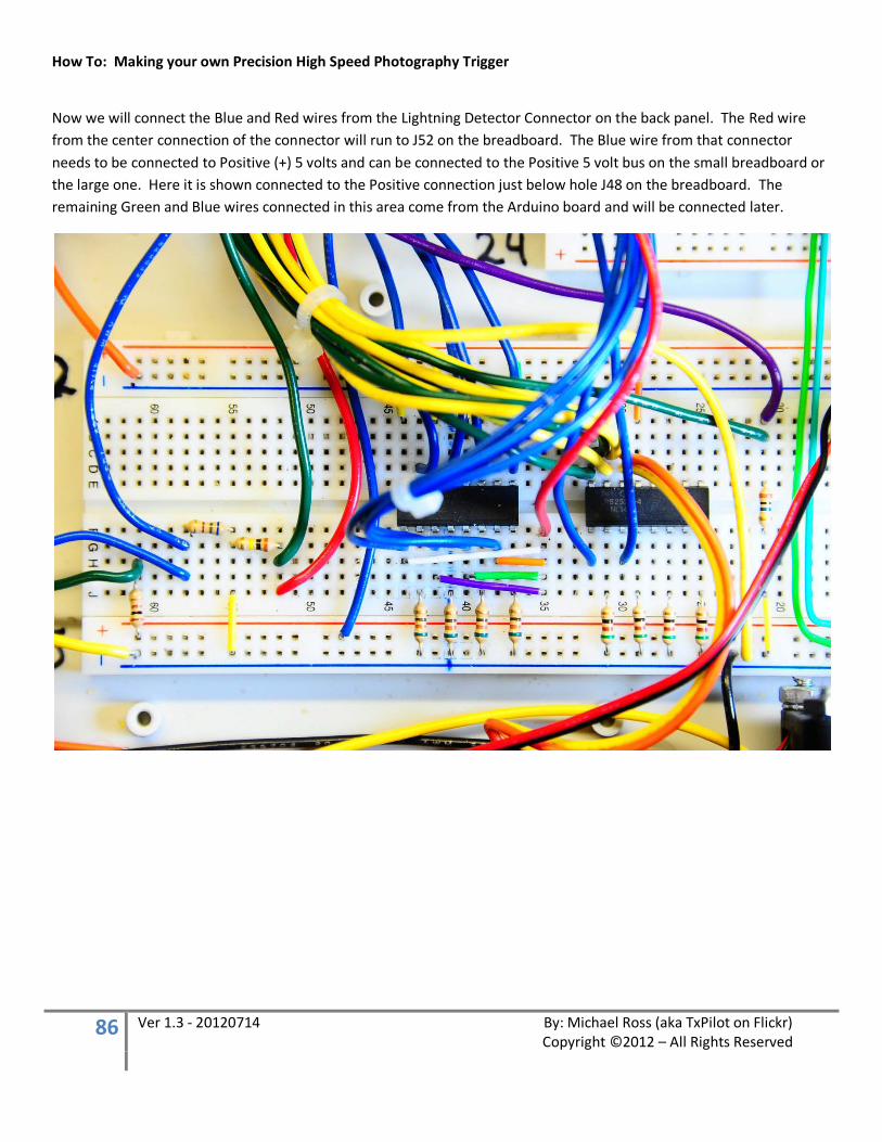
How To: Making your own Precision High Speed Photography Trigger
86 Ver 1.3 - 20120714 By: Michael Ross (aka TxPilot on Flickr) Copyright ©2012 – All Rights Reserved
Now we will connect the Blue and Red wires from the Lightning Detector Connector on the back panel. The Red wire from the center connection of the connector will run to J52 on the breadboard. The Blue wire from that connector needs to be connected to Positive (+) 5 volts and can be connected to the Positive 5 volt bus on the small breadboard or the large one. Here it is shown connected to the Positive connection just below hole J48 on the breadboard. The remaining Green and Blue wires connected in this area come from the Arduino board and will be connected later.

How To: Making your own Precision High Speed Photography Trigger
87 Ver 1.3 - 20120714 By: Michael Ross (aka TxPilot on Flickr) Copyright ©2012 – All Rights Reserved
WIRING THE CONNECTORS ON THE ARDUINO
Now we move to the connections on the Arduino board.
I used 4 different colors of wire and alternated them so that it would be easier to trace wires back when connecting them. Make sure you cut the wires long enough to reach from the Arduino board to the rest of the circuits on the breadboards even with the unit laid open. I used 90 degree headers to solder the wires to act as a connector and to help keep the wires out of the way of mounting the display through the enclosure.
Note that for Pins A1 through A6, the wires will need to be soldered to the holes on the LCD Keypad Shield as shown above. This may differ if you are using a different display or if you have a different version of this board. 90 degree header pins were used for pins A7 through A15 and also for Digital Pins 23 through 47 (in the photo above I have it going all the way from Digital Pin 23 through 53. Just in case I needed those additional pins for something later.
Total you will need 27 wires to solder to the pins for the Arduino board. One of these is actually no going to be used, but again, we will have it for later if we want to add something.
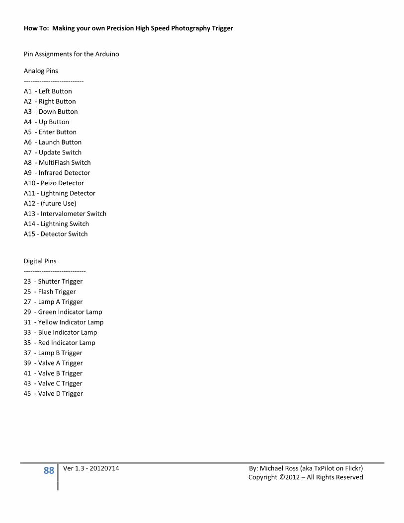
How To: Making your own Precision High Speed Photography Trigger
88 Ver 1.3 - 20120714 By: Michael Ross (aka TxPilot on Flickr) Copyright ©2012 – All Rights Reserved
Pin Assignments for the Arduino
Analog Pins --------------------------- A1 - Left Button A2 - Right Button A3 - Down Button A4 - Up Button A5 - Enter Button A6 - Launch Button A7 - Update Switch A8 - MultiFlash Switch A9 - Infrared Detector A10 - Peizo Detector A11 - Lightning Detector A12 - (future Use) A13 - Intervalometer Switch A14 - Lightning Switch A15 - Detector Switch
Digital Pins ---------------------------- 23 - Shutter Trigger 25 - Flash Trigger 27 - Lamp A Trigger 29 - Green Indicator Lamp 31 - Yellow Indicator Lamp 33 - Blue Indicator Lamp 35 - Red Indicator Lamp 37 - Lamp B Trigger 39 - Valve A Trigger 41 - Valve B Trigger 43 - Valve C Trigger 45 - Valve D Trigger

How To: Making your own Precision High Speed Photography Trigger
89 Ver 1.3 - 20120714 By: Michael Ross (aka TxPilot on Flickr) Copyright ©2012 – All Rights Reserved
Solder the connections to the 90 degree pins for the Arduino board first. This will make it easier to put the display and Arduino board into place, route and bundle the wires, then trim the other end of them to the length you need to help keep them even. Also, I would advise using some tape and markers to mark each wire showing the pin that it is connected to on the Arduino so you don’t have to do much in the line of tracing wires back to their origin point.
Once you have the wires soldered to the header pins for the Arduino and to the Analog ports on the LCD display shield, put the display in its place in the enclosure, run and bundle the wires, and then get ready to solder the ends of those that need to connect to the straight header pin connector. Follow the wiring diagram very closely to make sure you solder the correct wire to its matching pin.
You should trim the wire lengths for each one of these wires to make them the same length so that they will be easier to solder to the connector and won’t be pulling or pushing against each other when plugged into the breadboard.
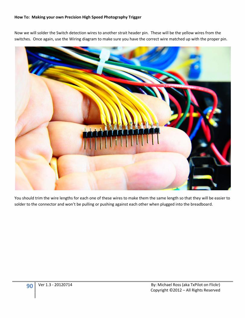
How To: Making your own Precision High Speed Photography Trigger
90 Ver 1.3 - 20120714 By: Michael Ross (aka TxPilot on Flickr) Copyright ©2012 – All Rights Reserved
Now we will solder the Switch detection wires to another strait header pin. These will be the yellow wires from the switches. Once again, use the Wiring diagram to make sure you have the correct wire matched up with the proper pin.
You should trim the wire lengths for each one of these wires to make them the same length so that they will be easier to solder to the connector and won’t be pulling or pushing against each other when plugged into the breadboard.

How To: Making your own Precision High Speed Photography Trigger
91 Ver 1.3 - 20120714 By: Michael Ross (aka TxPilot on Flickr) Copyright ©2012 – All Rights Reserved
Once you have these two header pin connectors completed, you can plug them into the small breadboard as shown below.
For connector A (from the switches), Pin 1 should plug into G1 on the breadboard and Pin 15 will plug into G15
For connector B (From the Arduino board), Pin 1 should plug into I1 on the breadboard and Pin 15 will plug into I15.

How To: Making your own Precision High Speed Photography Trigger
92 Ver 1.3 - 20120714 By: Michael Ross (aka TxPilot on Flickr) Copyright ©2012 – All Rights Reserved
FINISHING UP THE MAIN UNIT
So all we have left to do is to plug the rest of the wires from the Arduino into the breadboards, Indicator Lights, and Lamp Control connectors! The fun part is almost over! ;-)
We will tackle the Indicator lights first. Follow the wiring diagram closely in relation to the connections here.
The wire coming from Digital Pin 35 on the Arduino needs to be connected to the positive side of the Red Indicator lamp
The wire coming from Digital Pin 33 on the Arduino needs to be connected to the positive side of the Blue Indicator lamp
The wire coming from Digital Pin 31 on the Arduino needs to be connected to the positive side of the Yellow Indicator lamp
The wire coming from Digital Pin 29 on the Arduino needs to be connected to the positive side of the Green Indicator lamp.
The negative sides of the Indicator lamps need to be connected to Negative (-) on any one of the power strips on the breadboards.
Now on to the Lamp controls.
The wire coming from Digital Pin 27 on the Arduino board needs to be connected to the Lamp 1 connector.
The wire coming from Digital Pin 37 on the Arduino board needs to be connected to the Lamp 2 connector.
Then make sure you have the Negative (-) or ground connections on the Lamp connectors connected to the negative (-) side of one of the power strips on the breadboards.
And now, the Solenoid Valve controls
The wire coming from Digital pin 39 on the Arduino board needs to be connected to G44 on the large breadboard
The wire coming from Digital pin 41 on the Arduino board needs to be connected to G42 on the large breadboard
The wire coming from Digital pin 43 on the Arduino board needs to be connected to G40 on the large breadboard
The wire coming from Digital pin 45 on the Arduino board needs to be connected to G38 on the large breadboard
How To: Making your own Precision High Speed Photography Trigger
93 Ver 1.3 - 20120714 By: Michael Ross (aka TxPilot on Flickr) Copyright ©2012 – All Rights Reserved
We are in the home stretch now!
The last three wires from the Arduino will connect as follows to the large breadboard
The Wire coming from Analog Pin A10 will connect to A21 on the large breadboard
The Wire coming from Analog Pin A11 will connect to H52 on the large breadboard
The Wire coming from Analog Pin A9 will connect to G58 on the large breadboard
OKAY!!! THE WIRING SHOULD BE COMPLETED NOW!!!! For the main unit!
TIME FOR SOME BASIC TESTING!!!

How To: Making your own Precision High Speed Photography Trigger
94 Ver 1.3 - 20120714 By: Michael Ross (aka TxPilot on Flickr) Copyright ©2012 – All Rights Reserved
LOADING THE SOFTWARE
At this point, if you have not done so already, you need to download the Arduino software from the Arduino website and install it on your computer. You will also need to make sure the drivers for the Arduino Mega board are installed and that you are able to communicate to your Arduino board through a USB port.
The Arduino website is located at:
http://www.arduino.cc/
The download for the software is located at:
http://arduino.cc/en/Main/Software
Once you have the software downloaded and the drivers installed, you can run a quick test to make sure everything is working by loading the BLINK sketch that comes with the Arduino download. Open the sketch and download it to your Arduino. If everything is working properly, you will not see any errors in the Arduino window and the Red LED on the Arduino board should start blinking on and off in one second blinks.
If things do not seem to be working as they should, consult the Arduino website troubleshooting guide to try to get the problem resolved. If you contact me with Arduino problems, I am going to send you right back to their website so that you can troubleshoot it yourself. I can’t spend time working out Arduino communications issues with everyone. Every computer is different and you will just have to try to work Arduino problems out yourself.
Here is a link to the Arduino Troubleshooting guide:
http://arduino.cc/en/Guide/Troubleshooting
Once you have the kinks worked out and you have tested your Arduino environment successfully, you will need to download the memory Initialization script and run it one time before uploading the main script.
The Initialization script is located at:
http://www.mrossphoto.com/PHSPT/High_Speed_Trigger_Memory_Initialization_pde.pde
Here is a video of what you should see on the display when running this script.
http://www.mrossphoto.com/PHSPT/InitializationProgramVideo.avi

How To: Making your own Precision High Speed Photography Trigger
95 Ver 1.3 - 20120714 By: Michael Ross (aka TxPilot on Flickr) Copyright ©2012 – All Rights Reserved
Once you have made it past the initialization script successfully, it is time to load and upload the sketch for the Precision High Speed Photography Trigger.
The sketch is located at the following link:
http://www.mrossphoto.com/PHSPT/Precision_High_Speed_Photography_Trigger_v2.pde
Copy the text code from this file into a blank Arduino window and then press the upload button. The script should be uploaded to the board and you will be ready for testing.
You can now unplug the USB cable so that we can power the unit from our external power supply.
Plug in the external power supply and turn the unit on. If you don’t see any of the Magic Blue Smoke escape, then you have passed the first test!
Now take a look at the following video and go through all of the switches to make sure each of them update the display properly and that you can get into update mode and move through and change the parameters.
Here is a video of what that should look like.
http://www.mrossphoto.com/PHSPT/InitializationProgramVideo.avi

How To: Making your own Precision High Speed Photography Trigger
96 Ver 1.3 - 20120714 By: Michael Ross (aka TxPilot on Flickr) Copyright ©2012 – All Rights Reserved
CABLE WIRING
Most of the cables I used with this project were kits purchased from HiViz.com which I then added my own connectors to. You can really use any type of connection that you want just as long as the connections through the connectors end up in the same place when plugged into the back of the unit.
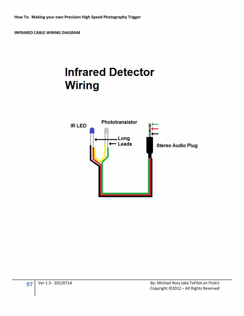
How To: Making your own Precision High Speed Photography Trigger
97 Ver 1.3 - 20120714 By: Michael Ross (aka TxPilot on Flickr) Copyright ©2012 – All Rights Reserved
INFRARED CABLE WIRING DIAGRAM
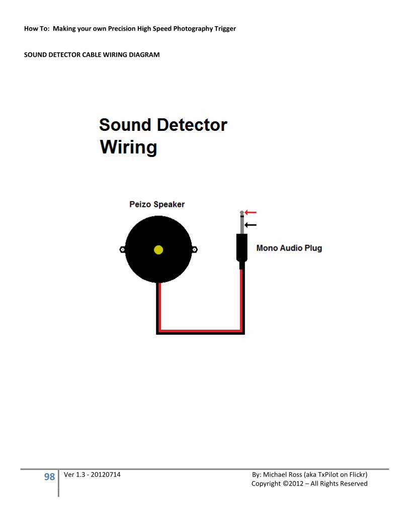
How To: Making your own Precision High Speed Photography Trigger
98 Ver 1.3 - 20120714 By: Michael Ross (aka TxPilot on Flickr) Copyright ©2012 – All Rights Reserved
SOUND DETECTOR CABLE WIRING DIAGRAM
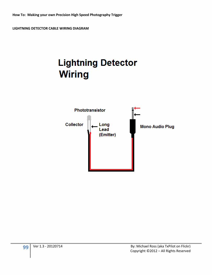
How To: Making your own Precision High Speed Photography Trigger
99 Ver 1.3 - 20120714 By: Michael Ross (aka TxPilot on Flickr) Copyright ©2012 – All Rights Reserved
LIGHTNING DETECTOR CABLE WIRING DIAGRAM

How To: Making your own Precision High Speed Photography Trigger
100 Ver 1.3 - 20120714 By: Michael Ross (aka TxPilot on Flickr) Copyright ©2012 – All Rights Reserved
HOT SHOE ADAPTER CABLE WIRING DIAGRAM
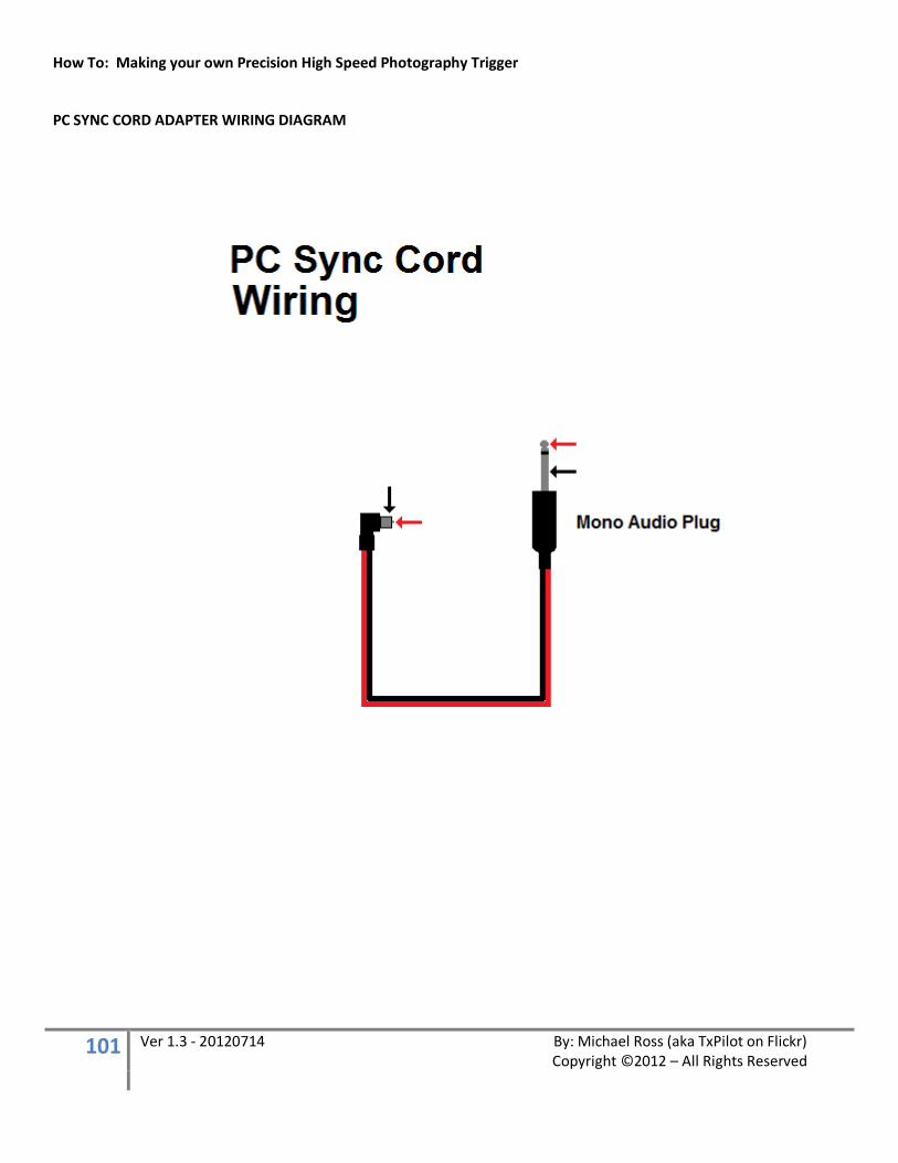
How To: Making your own Precision High Speed Photography Trigger
101 Ver 1.3 - 20120714 By: Michael Ross (aka TxPilot on Flickr) Copyright ©2012 – All Rights Reserved
PC SYNC CORD ADAPTER WIRING DIAGRAM
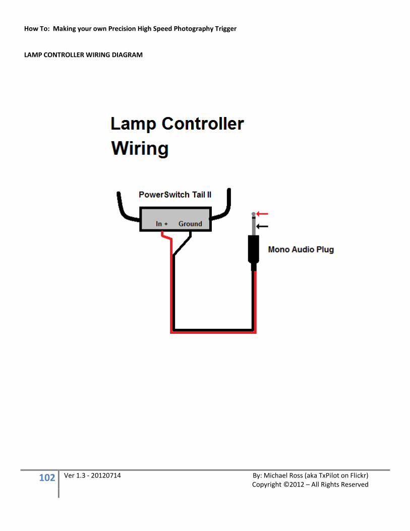
How To: Making your own Precision High Speed Photography Trigger
102 Ver 1.3 - 20120714 By: Michael Ross (aka TxPilot on Flickr) Copyright ©2012 – All Rights Reserved
LAMP CONTROLLER WIRING DIAGRAM
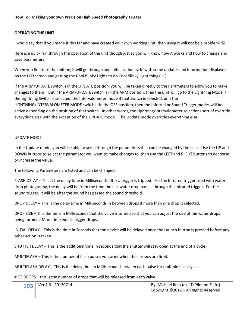
How To: Making your own Precision High Speed Photography Trigger
103 Ver 1.3 - 20120714 By: Michael Ross (aka TxPilot on Flickr) Copyright ©2012 – All Rights Reserved
OPERATING THE UNIT
I would say that if you made it this far and have created your own working unit, then using it will not be a problem!
Here is a quick run through the operation of the unit though just so you will know how it works and how to change and save parameters.
When you first turn the unit on, it will go through and initialization cycle with some updates and information displayed on the LCD screen and getting the Cool Blinky Lights to do Cool Blinky Light things! ;-)
If the ARM/UPDATE switch is in the UPDATE position, you will be taken directly to the Parameters to allow you to make changes to them. But if the ARM/UPDATE switch is in the ARM position, then the unit will go to the Lightning Mode if the Lightning Switch is selected, the Intervalometer mode if that switch is selected, or if the LIGHTNING/INTERVALOMETER MODE switch is in the OFF position, then the Infrared or Sound Trigger modes will be active depending on the position of that switch. In other words, the Lightning/Intervalometer selections sort of override everything else with the exception of the UPDATE mode. The Update mode overrides everything else.
UPDATE MODE
In the Update mode, you will be able to scroll through the parameters that can be changed by the user. Use the UP and DOWN buttons to select the parameter you want to make changes to, then use the LEFT and RIGHT buttons to decrease or increase the value.
The following Parameters are listed and can be changed.
FLASH DELAY – This is the delay time in Milliseconds after a trigger is tripped. For the Infrared trigger used with water drop photography, the delay will be from the time the last water drop passes through the infrared trigger. For the sound trigger, it will be after the sound has passed the sound threshold.
DROP DELAY – This is the delay time in Milliseconds in between drops if more than one drop is selected.
DROP SIZE – This the time in Milliseconds that the valve is turned so that you can adjust the size of the water drops being formed. More time equals bigger drops.
INITIAL DELAY – This is the time in Seconds that the device will be delayed once the Launch button is pressed before any other action is taken.
SHUTTER DELAY – This is the additional time in seconds that the shutter will stay open at the end of a cycle.
MULTIFLASH – This is the number of flash pulses you want when the strobes are fired.
MULTIFLASH DELAY – This is the delay time in Milliseconds between each pulse for multiple flash cycles.
# OF DROPS – this is the number of drops that will be released from each valve.
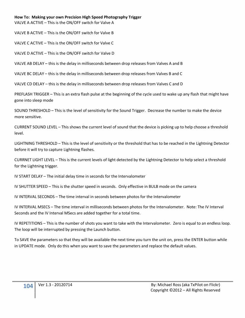
How To: Making your own Precision High Speed Photography Trigger
104 Ver 1.3 - 20120714 By: Michael Ross (aka TxPilot on Flickr) Copyright ©2012 – All Rights Reserved
VALVE A ACTIVE – This is the ON/OFF switch for Valve A
VALVE B ACTIVE – This is the ON/OFF switch for Valve B
VALVE C ACTIVE – This is the ON/OFF switch for Valve C
VALVE D ACTIVE – This is the ON/OFF switch for Valve D
VALVE AB DELAY – this is the delay in milliseconds between drop releases from Valves A and B
VALVE BC DELAY – this is the delay in milliseconds between drop releases from Valves B and C
VALVE CD DELAY – this is the delay in milliseconds between drop releases from Valves C and D
PREFLASH TRIGGER – This is an extra flash pulse at the beginning of the cycle used to wake up any flash that might have gone into sleep mode
SOUND THRESHOLD – This is the level of sensitivity for the Sound Trigger. Decrease the number to make the device more sensitive.
CURRENT SOUND LEVEL – This shows the current level of sound that the device is picking up to help choose a threshold level.
LIGHTNING THRESHOLD – This is the level of sensitivity or the threshold that has to be reached in the Lightning Detector before it will try to capture Lightning flashes.
CURRNET LIGHT LEVEL – This is the current levels of light detected by the Lightning Detector to help select a threshold for the Lightning trigger.
IV START DELAY – The initial delay time in seconds for the Intervalometer
IV SHUTTER SPEED – This is the shutter speed in seconds. Only effective in BULB mode on the camera
IV INTERVAL SECONDS – The time interval in seconds between photos for the Intervalometer
IV INTERVAL MSECS – The time interval in milliseconds between photos for the Intervalometer. Note: The IV Interval Seconds and the IV Interval MSecs are added together for a total time.
IV REPETITIONS – This is the number of shots you want to take with the Intervalometer. Zero is equal to an endless loop. The loop will be interrupted by pressing the Launch button.
To SAVE the parameters so that they will be available the next time you turn the unit on, press the ENTER button while in UPDATE mode. Only do this when you want to save the parameters and replace the default values.

How To: Making your own Precision High Speed Photography Trigger
105 Ver 1.3 - 20120714 By: Michael Ross (aka TxPilot on Flickr) Copyright ©2012 – All Rights Reserved
IR Detector Mode
In water drop photography, the IR Detector is used to
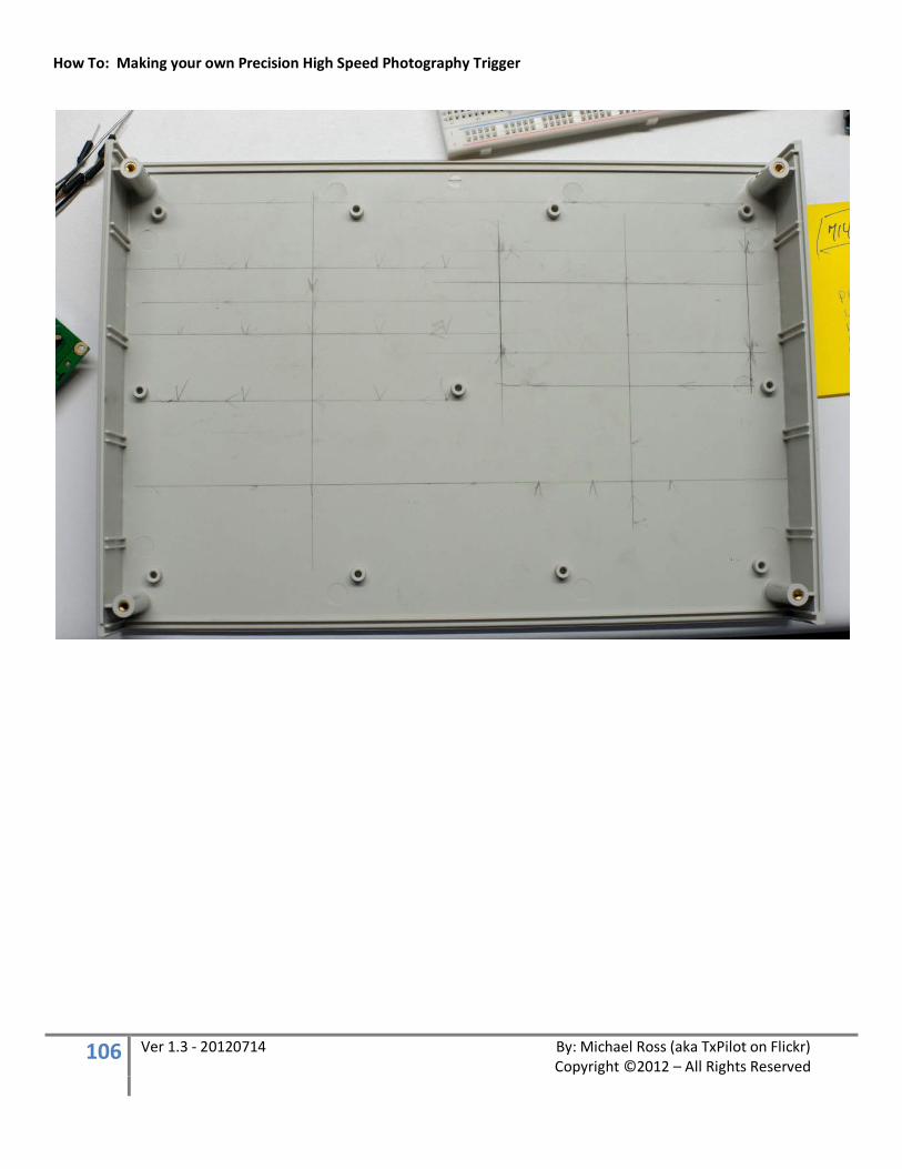
How To: Making your own Precision High Speed Photography Trigger
106 Ver 1.3 - 20120714 By: Michael Ross (aka TxPilot on Flickr) Copyright ©2012 – All Rights Reserved

How To: Making your own Precision High Speed Photography Trigger
107 Ver 1.3 - 20120714 By: Michael Ross (aka TxPilot on Flickr) Copyright ©2012 – All Rights Reserved
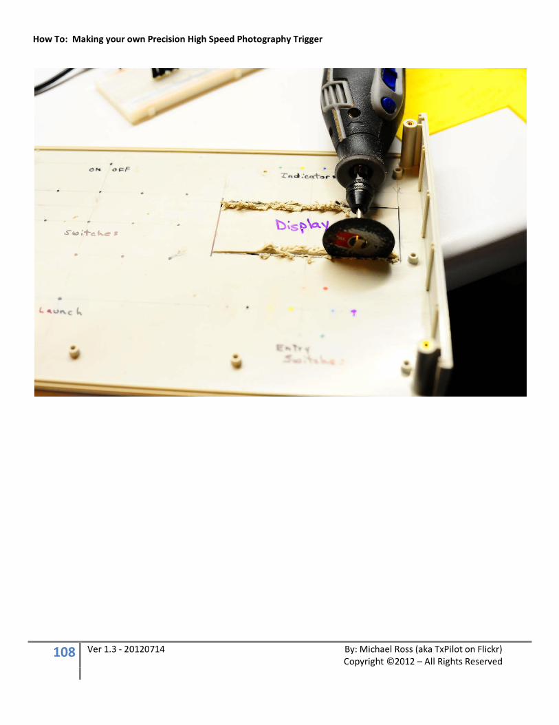
How To: Making your own Precision High Speed Photography Trigger
108 Ver 1.3 - 20120714 By: Michael Ross (aka TxPilot on Flickr) Copyright ©2012 – All Rights Reserved
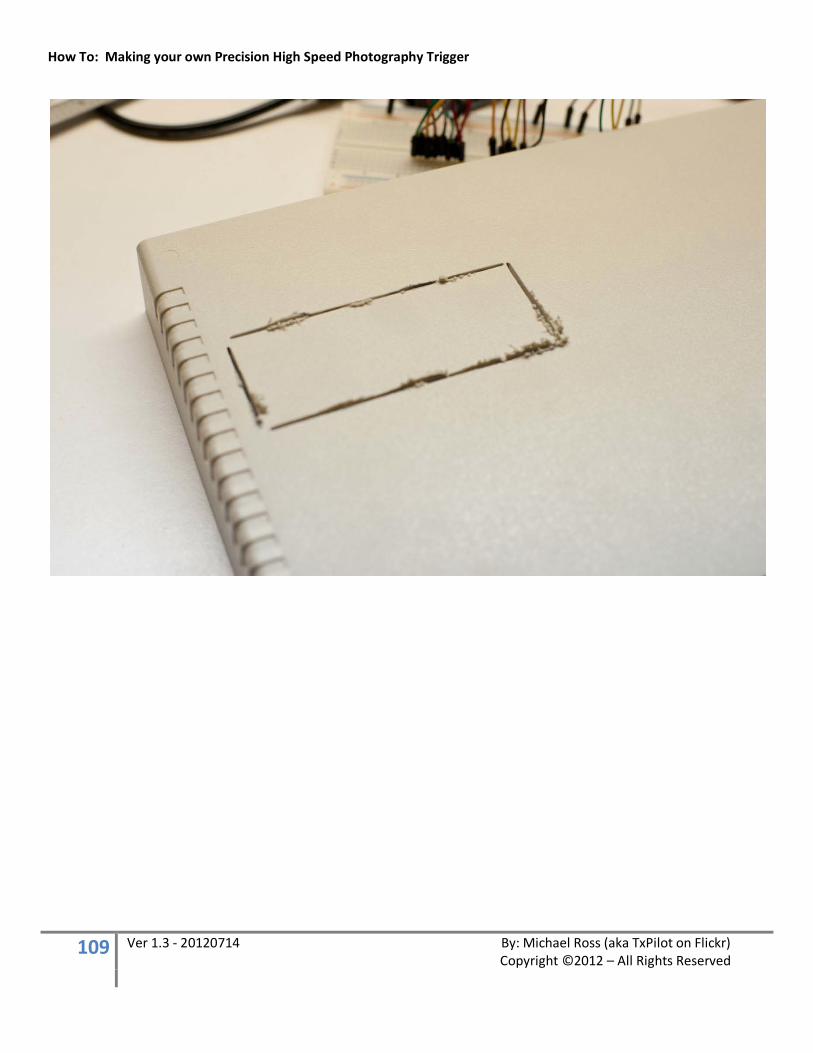
How To: Making your own Precision High Speed Photography Trigger
109 Ver 1.3 - 20120714 By: Michael Ross (aka TxPilot on Flickr) Copyright ©2012 – All Rights Reserved
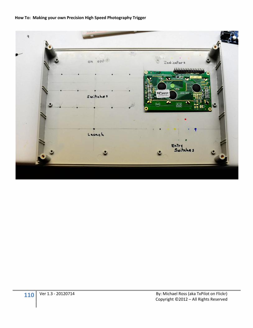
How To: Making your own Precision High Speed Photography Trigger
110 Ver 1.3 - 20120714 By: Michael Ross (aka TxPilot on Flickr) Copyright ©2012 – All Rights Reserved
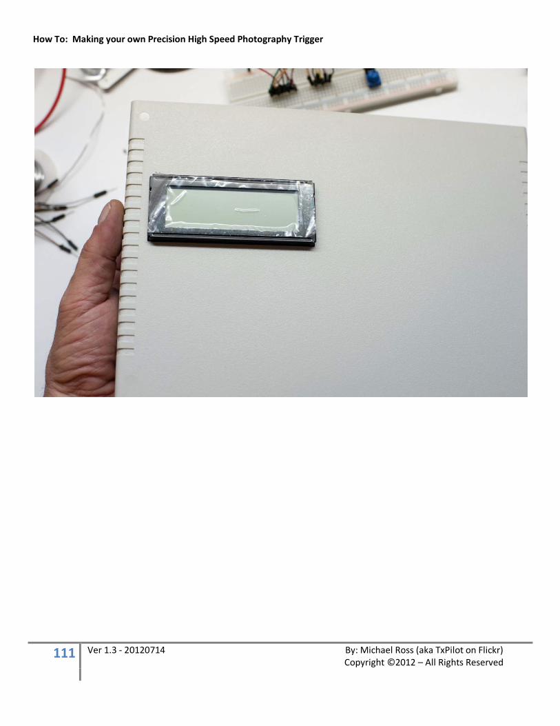
How To: Making your own Precision High Speed Photography Trigger
111 Ver 1.3 - 20120714 By: Michael Ross (aka TxPilot on Flickr) Copyright ©2012 – All Rights Reserved
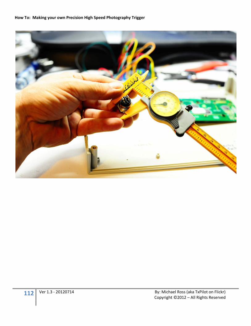
How To: Making your own Precision High Speed Photography Trigger
112 Ver 1.3 - 20120714 By: Michael Ross (aka TxPilot on Flickr) Copyright ©2012 – All Rights Reserved

How To: Making your own Precision High Speed Photography Trigger
113 Ver 1.3 - 20120714 By: Michael Ross (aka TxPilot on Flickr) Copyright ©2012 – All Rights Reserved

How To: Making your own Precision High Speed Photography Trigger
114 Ver 1.3 - 20120714 By: Michael Ross (aka TxPilot on Flickr) Copyright ©2012 – All Rights Reserved
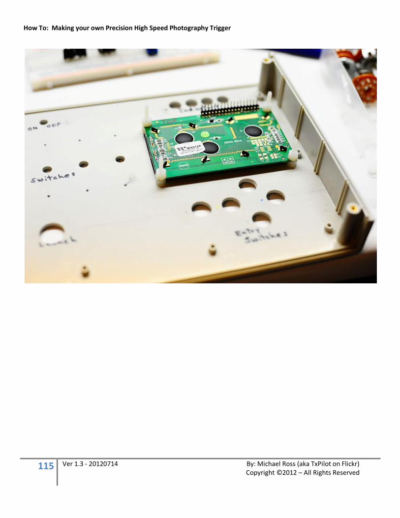
How To: Making your own Precision High Speed Photography Trigger
115 Ver 1.3 - 20120714 By: Michael Ross (aka TxPilot on Flickr) Copyright ©2012 – All Rights Reserved
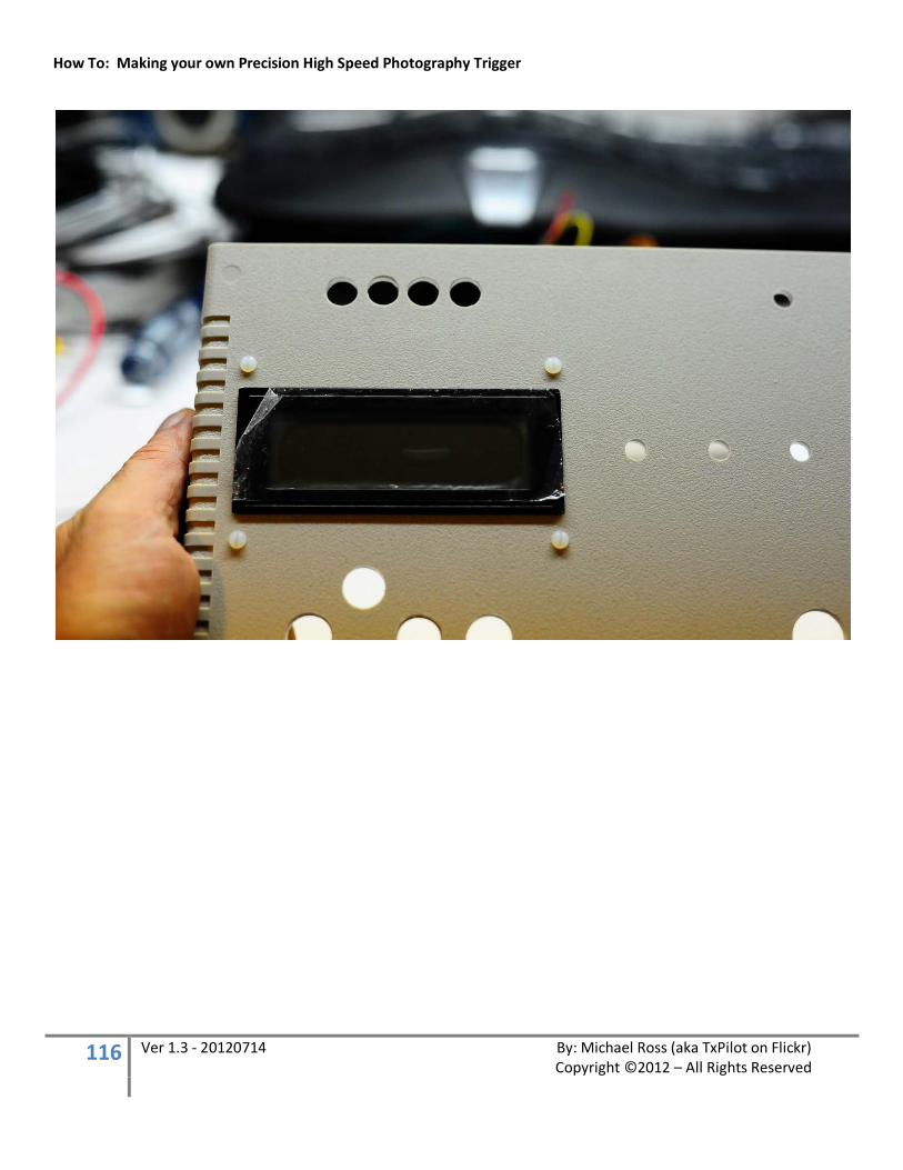
How To: Making your own Precision High Speed Photography Trigger
116 Ver 1.3 - 20120714 By: Michael Ross (aka TxPilot on Flickr) Copyright ©2012 – All Rights Reserved
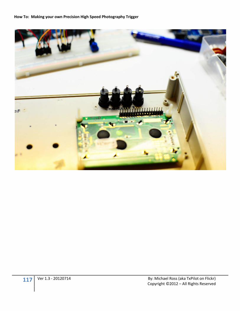
How To: Making your own Precision High Speed Photography Trigger
117 Ver 1.3 - 20120714 By: Michael Ross (aka TxPilot on Flickr) Copyright ©2012 – All Rights Reserved
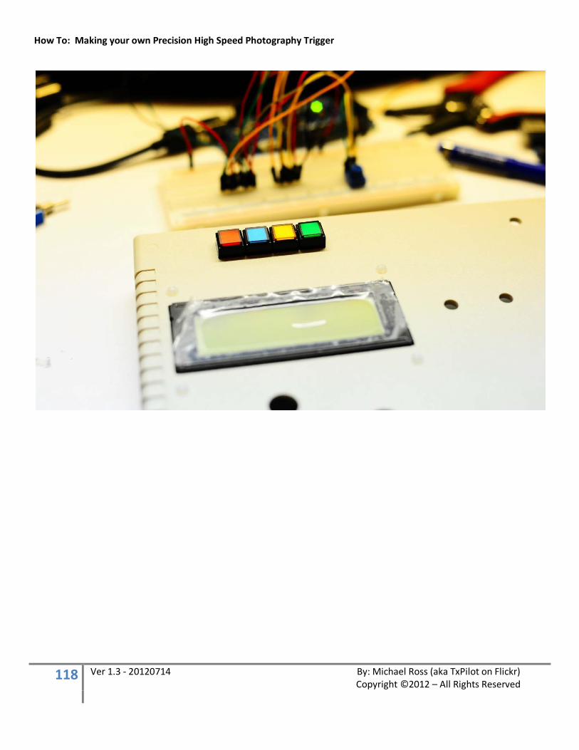
How To: Making your own Precision High Speed Photography Trigger
118 Ver 1.3 - 20120714 By: Michael Ross (aka TxPilot on Flickr) Copyright ©2012 – All Rights Reserved
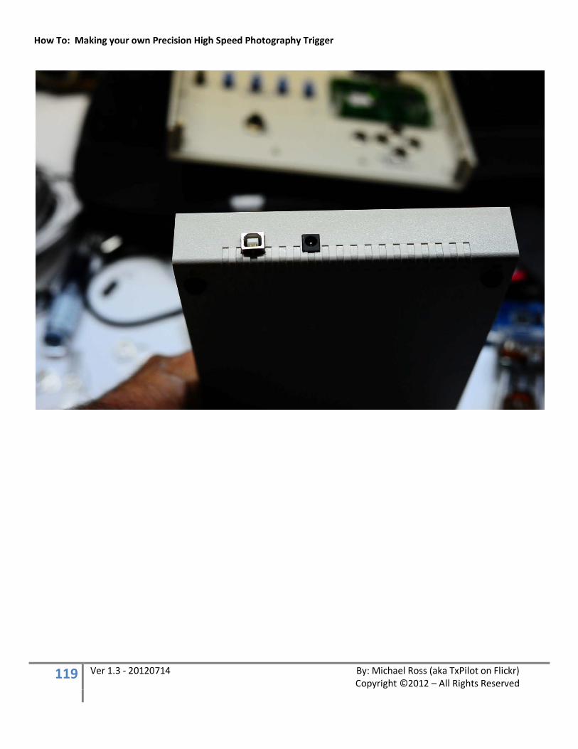
How To: Making your own Precision High Speed Photography Trigger
119 Ver 1.3 - 20120714 By: Michael Ross (aka TxPilot on Flickr) Copyright ©2012 – All Rights Reserved
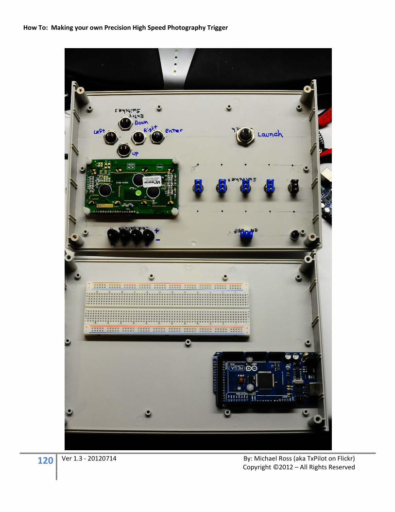
How To: Making your own Precision High Speed Photography Trigger
120 Ver 1.3 - 20120714 By: Michael Ross (aka TxPilot on Flickr) Copyright ©2012 – All Rights Reserved
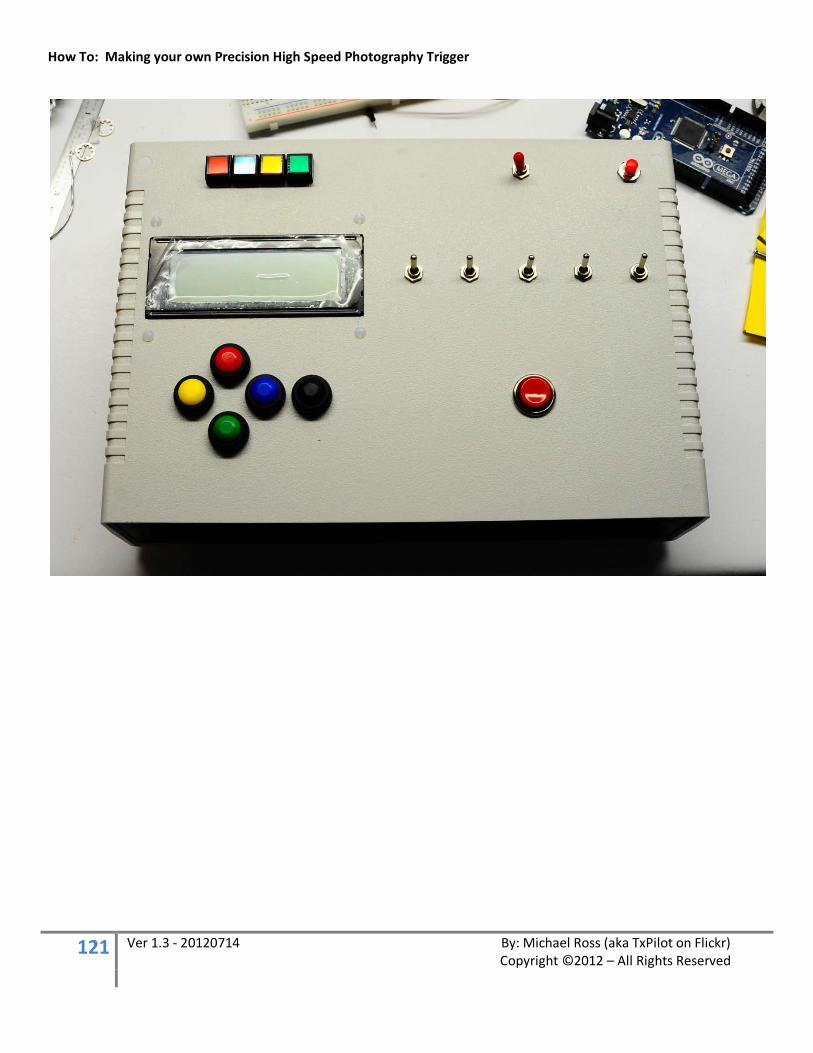
How To: Making your own Precision High Speed Photography Trigger
121 Ver 1.3 - 20120714 By: Michael Ross (aka TxPilot on Flickr) Copyright ©2012 – All Rights Reserved