precision flexible machining cell within a manufacturing
TRANSCRIPT

Precision Flexible Machining Cells within a
Manufacturing System
Mark K. Cutkosky, Paul S. Fussell, and Robert Milligan, Jr. Carnegie-Mellon University and the Robotics Institute
Pittsburgh, Pennsylvania 15213
March 1983
Abstract
This report discusses the conceptual design of a manufacturing cell for a small-batch manufacturer. The cell produces precision parts with a minimum of machining equipment. The cell design emphasizes near-term technology and uses off the shclf items where possible. The proposed cell can run unattended for a moderate period of time (eg. over-night). The design philosophy is to treat the cell components and control programs as discrete modules in a hierarchy. The resulting cell is easily integrated into a larger system. It is also readily modified or expanded as more sophisticated equipment and techniques become available.
Copyright @ 1983 Mark R. Cutkosky, Paul S. Fussell, and Robert Milligan, Jr.
This research has been hnded by the Fxonomic Development Committee of the Allegheny Conference on Community Development, the Robotics Institute, and Carnegic-Mellon University. This report is adapted from a document produced for the Economic Development Committee in Octobcr, 1982.


i
Table of Contents 1. Introduction 2. Design and Jmplementation Philosophy 3. The Machining Cell
3.1. Cell Capability 3.2. Autonomy 3.3. Cell Components 3.4. Cell Operation
3.4.1. Steady State 3.4.2. Between Part Runs
3.5. Skills needed to Develop and Maintain the Cell 3.6. Problems
3.6.1. Design problems 3.6.2. Runtime problems
3.7. Alternatives for the Future
4.1. System Definition 4.2. System Capability 4.3. Modifications at the Cell Level 4.4. System Components
4. Cell Intcgration into a Manufacturing System
5. Summary 6. Acknowledgements
1 3 4 7
12 13 19 21 27 30 31 31 32 33 34 35 35 36 36 40 40


ii
Figure 1-1: Figure 2-1: Figure 2-2: Figure 3-1: Figure 3-2: Figure 3-3: Figure 3-4: Figure 3-5: Figure 4-1:
List of Figures The Manufacturing System with Component Cells Hierarchical System Design The Machining Cell Communication Topology Typical Finished Part Made From Bar-Stock Machining Cell Layout -- First Arrangement First Variation on Machining Cell Layout -- Second Arrangement Second Variation on Machining Cell Layout -- Third Arrangement Cell Host-Controller Communication Scheme A Schematic of the Manufacturing System and the Factory Support Environment
2 5 6 8 9
10 10 11 37


1
1. Introduction Manufacturing cells have been promoted by a number of researchers [Bjorke 79, Bourne 82a, Merchant
80, Wright 82a, Wright 82b]. A manufacturing cell is a group of machine tools and associated materials
handling equipment that is managed by a supervisory computer. The cells are independent units but may be
tied together as shown in Figure 1-1 to form a flexible manufacturing system. Several systems of this kind are
currently being built in the United States and overseas [Gunn 82, Houston 81a. Krousc 811. A number of difficulties, however, are hindering the construction of flexible machining cells that produce precision parts.
In particular: The positional accuracy of industrial robots is poorer than the accuracy required for precision
parts loading; the controllers for existing machine tools and robots are not designed to be supervised by a
central computer; the techniques used to automatically monitor and control machining activities are not
developed to the point where a cell can be trusted to run without human supervision; and the sofiware for
coordinating activities and machines within the cell is still largely a subject of research.
In spite of these problems, the design for a flexible cell producing precision parts becomes feasible if we are
willing to do some development and to accept a cell that initially will depend on human supervision. In
particular, the following solutions are needed for the difficulties cited above:
0 Grippers and precision fixtures will have to be carehlly designed to achieve accurate part set-up with relatively inaccurate robots. Given the state of the art, robotic applications generally require the design and construction of special grippers and fixtures.
0 Sensors will be required to provide data about the status of the cell. The sensors will vary from air gap devices in the fixtures, to limit switches and load cells on the grippers, to a vision system which locates incoming parts and verifies the integrity of machined parts.
0 Machine tool controllers will have to be modified so they can become components of the cell managed by a single computer controlling the cell, the cell host. The cell host will need to schedule the actions of the machine tools and it will gather information from the tools (including robots). The first modification to the controllers will give the cell host a straightforward way of communicating with them. Software will also be developed to manage the cell; both short term scheduling and longer term maintenance can be managed by the cell host computer.
Although the tasks listed above show that a considerable amount of development is needed to complete a
precision machining cell it is possible to create the cell in a evolutionary way. Intermediate experience can be
applied to the developing cell as it progresses from the initial implementation to a more advanced form. To
make the evolutionary approach successful, the initial design includes the long-term goals of flexibility and
autonomy. In keeping with this philosophy, we structure the cell control as a hierarchy. The cell host
computer is responsible fot activities like parts flow and machine coordination. The machine controllers act
as interfaces between the cell host and the machining or handling processes and they control the individual
machines. Sensors provide information to the machine tools and to the cell host computer.

2
Factory Local Links to CAD and
Maunfacturing System Com put e r
Area Network
Machine Tool
'c" Machine Tool \ Machine Tool
Machining Cell
Machining Cell
W Machine Tool
Figure 1-1: The Manufacturing System with Component Cells
The evolutionary development is also eased if the cell host can view the machine tools as inputloutput
modules (where the input and output are parts). The idiosyncrasies of each machine are hidden from the cell
host so that all the host sees is the module. In this way, new machines can be easily added and the old
machines can be modified with little concern about side effccrs in the ccll host computer. On a grander scale,
as the cells are integrated into a flexible manufacturing system the system level computer is able to view the

3
cclls as inputloutput modules and will not need to concern itself with the dctailcd operation of each cell.'
The dcsign which meets these requirements .provides a systematic framework in which a hnctioning
precision ccll can be built and thcn intcgratcd into a larger manufacturing systcm. The dcsign uses equipment
which for the most part is available in today's markctplace. The robotic manipulators, the machine tools and
the sensors arc all available in rudimentary form. What is not availablc can be dcvclopcd along trends visible
today. Thus, during the early stages of the installed cell it may be necessary to have a human operator oversee
the machining operations and ensure, for example, that a tool breakage has not occurrcd. The ccll could
hnction in this way until an automatic system for monitoring such problems was devclopcd. Then the cell
could approach operation indcpendent of thc human operator.
2. Design and Implementation Philosophy Thc hcart of the dcsign is flcxibility. Our intent is to develop a cell that will produce a variety of product
forms and fit in a manufacturing system with other cells. The cell that will satisfy these needs is complex . 'To make thc implementation of the design tractable, the dcsign philosophy is founded on two principles:
1. the cell and its component parts and pieces must be modular, and
2. the ccll and its components fit in a structured hierarchy.
The former idea is simply justified. The modular parts, whether they are grippers, fixtures, lathcs, or
software communication drivers, can be individually designed if care is given to the specification which
dcfincs how the modules fit together. If a module is dcsigned strictly as something that can operate on an
input and producc an output, then the input-output Characteristics define the modulc. If the modules are
built to these specifications, then the integration of the modules into the whole is simplified, the whole is easy
to understand, and debugging the system is simplified. By the same token, eventual modification of the cell is
made easier.
The second principle provides the design with several nice features. The cell can be viewed from any of the
levels of the hicrarchy. If the viewer is interested in the input-output characteristics of the cell, that
information is readily available from the hicrarchy. But, if the viewer wishes to inspect features of thc cell
much lowcr in the hicrarchy, such as individual protocols between controllers and the supervisor, the
information is equally available, just at a different, bur well dejined, place. One compelling feature of the
combination of thcse principles is the ease with which one can change lower elements of the hierarchy
'The concept seems straightfonvard but we have found it surprisingly easy to make concessions to a particular controller or process that prevent it rrom behaving as an independent module.

4
without adversely affccting thc highcr elcmcnts. The only rcquircmcnt is that thc low-order modification not
change the function (or input-output characteristic) of the module.
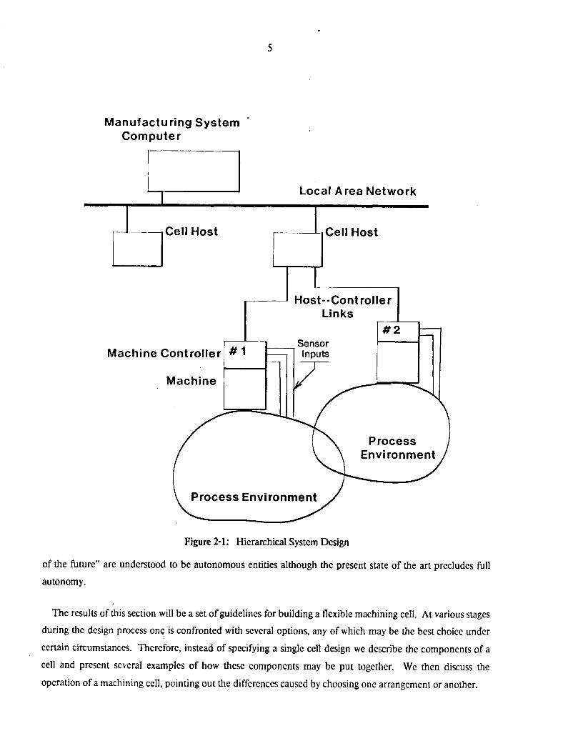
Figure 2-1 is a conceptual picture of the hicrarchy. The machine tools (robot, mill, lathe, ctc) are
individually controlled by stand-alone computers. Thcse computers control thc machines in rcal time and act
as an interface to the cell host. Thcy hold responsibility over thc individual machincs, but also respond to
higher level commands from the ccll host computer. The ccll host is a largcr computcr system rcsponsiblc for
the scheduling of operations within the cell. But this computer, too, must act as an interface bctwecn the
machining cell and the computers at the manufacturing system levcl. The ccll host must be able to satisfy
requests from the higher level computers for data on the cell status.
The design described in this report is for a near-term cell; it cannot use components that will require more
than a couplc of years bcforc they are ready for industrial use. This restriction forces us to make a number of
compromises:
0 The design is restricted to existing computcr technology for the supervisor. There are also practical restrictions on how the computers within the cell are networkcd together. A star topology, with the supcrvisor at the center, is most likely due to the limitations of the machine controllers (see figure 2-2).
0 The design is restricted to cxisting robots and material handling devices. Robot technology is rapidly advancing, but by using today's equipment we bencfit from designs that have been tested in the marketplace (see section 3.3).
0 Thc sensors used throughout die cell will be simple. They will be used, for example, to dctect the prescncc of parts and to signal conditions such as dropped parts. By using readily available microswitchcs, linear variable differcntial transformers, optical sensors, and the like, we seriously limit the sophistication with which the cell can detect errors, but we are assured of reliable devices with simple interfacing requirements.
0 Existing controllers will either be modified or enhanced by strap-on microcomputers [Houston 81al.
0 Grippcrs and fixturing will be designed using conventional technology, and built from off-the- shelf components.
3. The Machining Cell In this section we cxamine the componcnts, the characteristics and the operations of a precision flexible
machining cell. In the jargon, a machining cell is generally assumed to include scveral numcrically controlled
machine tools, some materials handling equipment for transporting parts, a level of inter-machine
communication, and some supervisory control at the cell levcl. Manufacturing cclls for the so called "factory
5
Manufacturing System Corn pu te r
Machine Controller
Machine
Links
Sensor
Process Environment
Figure 2-1: Hierarchical System Design
of the future" are understood to be autonomous entities although the present state of the art precludes full
autonomy.
The results of this section will be a set of guidelines for building a flexible machining cell. At various stages during the design process one is confronted with several options, any of which may be the best choice under
certain circumstances. Therefore, instead of specifying a single cell design we describe the components of a
cell and present several examples of how these components may be put togethcr. We then discuss the
operation of a machining cell, pointing out the differences caused by choosing one arrangement or another.

6
-- / \
Limit of the Cell \
\ Local Area Network
Controller Link
/
Figure 2-2: The Machining Cell Communication Topology
In section 3.5 we look at the skills required to develop a machining cell and the skills needed to keep it
running. These skills arc nearly independent of the final cell arrangement and the discussion of them applies
to any of the examples given in sections 3.3 and 3.4.
Common problems encountered during the development of a cell, and problems to be expected during cell
operation, are discussed in section 3.6 along with a few remedies.
Finally, in section 3.7 we consider some alternatives that, while they are not practical for a near-term cell, '
look attractive for the future.
For common reference, some of the terms used frequently in this section are explained below:
0 cell host -- Thc host is the small computer, or computer system, that acts as supervisor for the cell. It manages the ccll operations and acts as the interface to the factory level computer system. Parts programs arc down-loaded to the machines through the cell host.
0 cell supervisor -- The ccll supervisor is the high-level program that runs on the cell host.

7
0 machine controller -- The controller is the computer that controls a particular machine. I t also acts as the interface betwecn the machine and the cell host. Machine, here, is used in a generic sense to mean any of the components that work in thc ccll including machine tools and robots.
0 machine tool -- The term machine tool is used as it is in general industrial experience, i.e. a machine tool is a powered device that removes matcrial from, or in some other way changes, the physical charactcristics of a work piece. Typical examples are lathes, mills, grinders, and so on.
0 robot -- In this cell, the robots are material handling devices with multiple dcgrces of freedom. They are equipped with specialized grippers for loading and unloading the machine tools.
0 fixturing -- The specialized tooling for holding and locating parts at different locations within the cell. Grippers on the robots are included as a special example of fixturing since they must locate and hold parts, just as the fixtures on machine tools do.
3.1. Cell Capability
As it turns out, the range of different parts that a precision cell can produce is chiefly determincd by the
fixturing within the cell. Machine tools can machine pieces anywhcre from an inch to over a foot on each side
and computers are as flexible as the programs written for them; but a robot gripper or a set of clamps can only
be expected to accommodate one or two basic families of parts without being changed. For the near term it is
unrealistic to attempt to develop "universal" fixtures. This is partihlarly true for a precision cell where the
close machining tolerances call, in turn, for precision fixtures. Thus, the fixturing in a machining cell
establishes a "window" limiting the sizes and shapes of parts that the cell can produce without human
intervention. A good example of a basic parts family that lies mostly within a single window would be:
"precision parts made from metal bar stock up to 25 square inches in cross section." This basic family is used
as an example for thc rest of this section.
Figure 3-1 shows a typical finished part from the bar-stock family. It requires most of the operations that
we would expect a small machining facility to perform (e.g., turning, drilling, reaming, tapping, boring,
milling). Practically speaking, the minimum equipment for producing these pieces (whether the machining is
done automatically or by hand) consists of a vertical axis mill and a lathe with a centering four jaw chuck.
The CNC (Computer Numerical Control) versions of these two machines form the core of our small flexible
machining cell. The CNC machines are serviced by materials handling equipment, including robots. Figures
3-2,3-3, and 3-4 show plan views of three possible configurations for the core elements of the machining cell.
The comparative advantages and disadvantages of these different arrangements will be discussed later in this
section.
-1
In our discussion of the cell we assume that parts will arrive presented to the cell in such a way that the
robots can accurately pick them up. Onc possibility, shown in figures 3-3 and 3-4, is for parts to arrive on cart

8
0 .812 cent. ->
A
c’bore two places, 1 8 0 apart, 2.500 dia. bc.
j i l t - 0.437 cent., typ.
e- 12-24 thd. thru, 2 places, 180 deg. apart, 2.375 dia. bc
r 0.375 I ~ 0 . 1 8 8 typ.
1 I 0.750 I
0.1 25 cent., typ.
section A-A
note: all dim.’s in inches, + 1- 0.003 material: cold-rolled steel
Figure 3-1: Typical Finished Part Made From Bar-Stock
which may be manually controlled or self-guided. This solution lends itself to forming a flexible
manufacturing system composed of several cells as suggested in section 4. The mechanics of acquiring and
handling precision parts are heated in section 3.4.1. The physical input to the cell will include new cutting
tools for the CNC machines as well as workpieces. Similarly, the ourput from the cell will include worn and
broken tools. The cutting tools generally will not resemble members of the parts family that the cell is

9
lathe loading robot
L_
table
Figure 3-2: Machining Cell Layout -- First Arrangement
designed to produce and they consequently pose some special handling problems which are discussed in
section 3.4.2.
It should be pointed out that the cell is not restricted to producing parts that require all the machining
operations mentioned above. The cell can perform any subset of the available machining operations.
Operating the cell with only some of machines is inefficient, but there are times when it is useful. For
example, if the lathe is temporarily out of commission the cell can produce pieces that require only milling.
The cell control system (see (I host computer section 3.3 ) should allow this sort of flexibility.
Figure 3-5 shows the machining cell from a different perspective. It is applicable to any of the three
physical arrangements shown earlier and provides a schematic of the cell control and communications
channels. The cell host computer is the heart of this schematic and the capabilities of the cell from the
standpoint of control and communications depend almost entirely on the host. The host will be responsible
for the interaction between all the components of the cell including the CNC machine tools, robots and vision

10
n
cnc mill 4 racl -
J
with stock
Figure 3-3: First Variation on Machining Cell Layout -- Second Arrangement
d 0 0
0 0
0 0
cart with stock
mill m- Figure 3-4: Second Variation on Machining Cell Layout -- Third Arrangement

11
system. The coordination of the machine actions will be the most complex thing the host does. The host will
also pass parts programs to the controllers. The parts programs themselves arc stored elsewhere (see section
4.4).
Local Area Network 7 Ope rator Terminal
Mill
Possible Sensor Inputs
Gripper K PC
Table
Vision System
7 Inputloutput
Ports
Figure 3-5: Cell Host-Controller Communication Scheme
The ccll should be able to provide statistical information to any higher level computer. The kind of data 1
the higher level computcr should have access to includes the following:
0 machinc tool operation time

12
0 the numbcr of parts proccsscd in the last time period (which should be a flexible nuinbcr, cg., batch, day, hour)
0 the numbcr of parts that came into the ccll in the last time pcriod
0 the number of incoming parts that wcre acccptable
0 thc numbcr of parts that wcre scrapped during the last time period
0 how much the various cutting tools have been used
0 what failurcs have occurred during processing
0 details of the failures
3.2. Autonomy
The flexible manufacturing cell is intended to be partially autonomous and the effects of this decision
appear throughout the design. The cquipment that moves materials through the cell and the cell host that
supcrviscs cell activities are provided for reasons of autonomy. The economic analysis of a cell is also closely
allied with its autonomous nature. The cost of the additional cquipment and software to run the cell without
people must balance the savings in reduced human intervention. This cost consideration probably rcsuicts
the initial construction of the cell to a development environment.
"Autonomous" implies more than automatic, though. The materials handling equipment and the cell host
allow the ccll to run automatically, but autonomous operation requircs somc additional features. In
particular, the ability of a cell to function indcpendently depends on its tolerance of errors. An autonomous
cell must be able to recognize bad incoming parts, to rccover from parts lost in process and to recover from
common failures such as tool breakage and part mis-alignment. Unfortunately, such errors are very difficult
to recognize and tolerate. This difficulty is the source of our decision to limit the cell to partially autonomous
operation, meaning that human operators will check things out now and again. The tasks that people perform
will be varied, but it is a goal of the design for this cell to reduce the time individuals spend at each task. This
amounts to incrcasing the productivity of thcse people. It would be an achievement to operate a cell for three
shifts with people attcnding it for only one of those shifts. This is a practical goal using today's technology
and in fact a number of morc specializcd manufacturing operations have started in Japan which are attended
by six people during the day shift and one person during each of two night shifts [Gunn 82).
An autonomous cell shoyld also have some rudimentary inspection capabilitics. In this design, we use
automated visual inspection both for locating incoming parts and for final part inspection. The final part
inspection is limited in the ncar-term cell. Complete, automatcd, gauging and inspection is not feasiblc for a

13
number of reasons. Automated visual inspection, while quite broad in its potential applications. is unable to
measure dimensions such as the depth of a blind hole or the diameter of an internal snap-ring groove. This is
m e for any physical characteristic where a profile image is not available. Programmable measuring
equipment that is not based on visual information is still extremely expensive, although the relative price of
coordinate measuring machines is beginning to drop. Programmable coordinate measuring machines are
more difficult to interface with the rest of the cell than are vision systems, and this is another factor that
excludes them from a near-term cell.
The near term cell will be able to chcck for simple faults with a variety of sensors, including video cameras.
It will respond to errors in machining or transporting parts by simply discarding the part in question and
recording the fact that a part was scrapped. Once the cell is running smoothly, the number of errors should be
small and the rejection rate is expected to be low.
3.3. Cell Components
In this section we describe the components that make up the machining cell. The primary manufacturing
elements are shown in figures 3-2, 3-3 or 3-4. The other major components are conceptually shown in figure
3-5.
CNCmachine tools:
o A vertical axis CNC milling machine. This machine tool should be equipped with closed- loop control of the position of the table and the spindle to provide positional accuracy on the order of +0.0005". 'The spindle speed should be software controllable. The mill should be equipped with a tool changer that will hold a large number of tools to accommodate work pieces requiring many different milling operations and to allow the processing of a variety of work pieces without pausing to install different tools in the tool changer. The power of the spindle drive motor is not critical for parts made from bar stock, such as the parts family discussed in section 3.1. Similarly the range of travel of the table and the spindle are not critical for these relatively small parts. Examples of a suitable machine tool include the Bridgeport BTC I and the Matsuura MC-SOOV vertical axis CNC milling machines.
o A horizontal axis CNC turret lathe. Like the milling machine described above, this machine tool should be equipped with closed-loop position control on all axes (in this case the longitudinal suoke or z-axis displacement and the cross stroke or x-axis displacement of the turret). This control will, like the control for the milling machine, be required to hold positional accuracy within the range of ~0.0005". The spindle speed should be software controllable. The number of tool positions available on the turret should be as large as possible to promote flexibility in machining complex and/or varied work pieces. Any less than, say, eight tool positions would significantly reduce this flexibility. It is unfortunately inherent in the design of a turret lathe that fewer tool positions are available on the turret than would be found on a typical tool changer for a milling machine. Neither the power of the spindle drive motor nor the range of travel of the turret in the x and z directions is

14
critical for the family of small work pieces under consideration. A typical example of a lathe of this type, size, and capability is the Miyano model CNC-6IK-3 turret lathe.
0 parts handling devices.
o A lathe loading robot. The lathe loading robot is a specialized manipulator designed to be able to reach into a CNC turret lathe for loading and unloading parts from the chuck. The commercially available lathe loading robots are not particularly sophisticated machines. In general they consist of two arms suspended from a carriage riding in an overhead track, rather like an overhead crane. One arm is usually used for loading new pieces into the lathe and the other for unloading finished pieces. The arms are pneumatic or hydraulic and operate by means of limit switches. The grippers at the ends of the arms may be pneumatic or hydraulic. Only the movement of the carriage in its track is continuously programmable. This is accomplished by driving the track with IX servo motors and either ball screws or a rack and pinion. Examples of commercially available equipment are the Manca "Doublc Arm Gantry System" and the IS1 lathe loading system. A more flexible (but more expensive) alternative to the specialized lathe-loading robot is to use a 5 or 6 axis robot, such as thc one described below, for tending the lathe. Another possibility is to mount the mill-loading robot on a track running between the mill and the lathe. These possibilities are illustrated in figures 3-3 and 3-4 and discussed below and in section 3.4.1.
o A mill-loading robot. This small robot requires at least five programmable axes to pick up a part from a flat surface and to orient it on the bed of a milling machine. With six axes the robot can place parts into fixturing that is arbitrarily inclined with respect to the horizontal or vertical. 'The robot should be quite accurate since it will be used for precision loading of parts into fixtures on the mill. A number of accurate, 5 or 6 axis robots are available. They include the Cincinnati Milacron T3-726, the ASEA IRb-6, the CRYO 820 and the Bcndix AA-160. The quoted repeatabilities of these machines are all within 20.008 inch. These robots are not large, but they will reach at least 30 inches and they will all handle at least 13 Ib. Thirty inches should be enough to reach both the center of the linear table and the bed on the milling machine shown in figure 3-2. A 13 Ib. limit for the robot arm effectively limits workpieces to 10 Ib. once a gripper is mounted. This is a bit restrictive for pieces that are not made from aluminum although we note that pieces can enter the cell weighing more than 10 Ib. if they first go to the lathe and weigh 10 Ib. or less after turning. If 101b. seems too restrictive, then one of the larger robots in this group such as the CRYO 820 or the Bcndix AA-160 should be picked. If the robot is to be used for loading the lathe in addition 'to the mill (as suggested in figures 3-3 and 3-4) it will probably require a reach of more that 30 inches. This is particularly true for figure 3-4 where the reach of the robot determines how far apart the machines can be placed. If the larger robots in the group above do not have enough reach then it will be necessary to use a robot such as the Cincinnati Milacron T3-746 or the ASEA IRb-60. For a precision cell, it is not desirable to pick a larger robot than necessary since the increased reach and payload come at the expense of accuracy. Another Consideration is that CNC lathes generally offer less clearance for loading and unloading than CNC mills do: this may rule out any robot with a bulky arm.' Figure 3-3 shows a very flexible arrangement in which the robot is mounted on a track to improve its reach. Some robots, however, have stringent mounting requirements and would not perform w&ll on a track.
'Some robots. such as the Bendix AA-160, can be mounted hanging upside-down from the wiling which would improve acces to the lathe.

15
Robot controllers are much the same as machine tool controllers and the integration problems with both are explained below under controllers. Some robots are much easier to program than others. The better ones provide coordinate transformation packages, tool or "hand" coordinates, and easily specified inputs and outputs for working the gripper. This is a distinct advantage but the state of the art in robot software is changing so rapidly that if a particular robot does not provide such amenities today, it may offer them in a few months.
a lineartable In figure 3-2 a linear table is used to transfer parts between the lathe loading robot and the mill loading robot. In addition, the table may stop beneath the camera of a vision system. The table cames a pallet with some simple fixtures to locate parts so that tlic robots can pick them up easily. The pallet should be big enough to hold several parts and will therefore offer a bit of in-process storage. The linear table must be quite accurate, but it need have only a few fixed stops. Linear transport tables are made by a number of manufacturers including SI Handling Systems.
a controllers Controllers for machines and parts handling equipment -- The controllers available in today's market provide good support for the operation of the individual machine tool. Our requirement, however, is to place a controller in an autonomous machining cell. This has two important consequences:
1. the controller must be able to send and receive complex messages from the cell host, and
2. the controller must allow the cell host to manage the took actions.
In particular, the controller must allow the cell host to do the following:
o Command the execution of programs and/or subprograms on the machine controller.
o Down-load parts programs to the machine controllers and receive up-loaded programs from the machine controller.
o Access the state of the machine controller. The access will consist of a message containing relevant information about the machine and its controller (including the robots). This is essential for the cell host to maintain a detailed account of the status of the cell.
There are additional functions the supervisor might want, but the list above already represents functions that no existing controller provides in a reasonable form. Most existing controllers do provide communications channels (generally some combination of parallel I/O ports and serial data lines) but few will allow a cell host to command the running or stopping of a controller program. Program up-load and down-load is provided on the more advanced controllers but it requires operator intervention. This is unacceptable for an autonomous cell. Solutions to this dilemma come in a couple of flavours, but basically involve either putting a small computer between the controller and the supervisor [Houston 81a, Houston 81b] or re-writing the controller software [Syiek 821. Presumably, the people who make machine tool controllers will begin to build controllers capable of supporting the functions above, but the industry is conservative. Such controllers may be avajlable in two years. The near-term controller that meets the requirements above will probably have a single serial line to interface to the cell host.
a a vision system

Automated visual inspection will be used both to locate incoming parts and to perform final part inspection. A numbcr of manufacturcrs produce what are essentially stand alone microprocessors combincd with a grcat deal of special purposc hardwarc and software, all designed to process images from onc or more vidco cameras. By process images we mean, roughly, the following: acquire an image (what amounts to a "snap-shot" of a particular field of view at a particular instant), convert the image to digital form, and perform a varicty of computational tasks on this digital information. Thc computational tasks rangc from simply rccognizing a distinct object to calculating its position and orientation within the field of view of the camera. Some of thc more important diffcrcnccs between various vision systems are:
o Vision systems, likc machinc controllers, are based upon a microprocessor. It follows that the more advanced the microproccssor used in a particular system, the more desirable the system. Along these lines, a vision system utilizing a microprocessor with a 16 bit architecture is preferable to one using a microprocessor with an 8 bit architecture.
o Just as machine controllers must support two-directional communication with thc cell host, so must vision systems. Furthermore, the necd to allow the cell host to control the system's actions is much the same for a vision system as for a machinc controller. Both of these characteristics are absent in some of the currently availablc commercial systems.
o All commcrcially availablc vision systems process pictures either as binary or as grey-scale images. Here the term binary implies that all images are seen as combinations of pure white and pure black dots or pixels. Grey-scale, on the other hand, implies that images arc seen as combinations not only of pure white and pure black pixels, but also of pixels having intermcdiate, or grey, levcls of light intensity associated with them. A vision system which provides grey-scale capabilities is more desirable than a binary system if the intended application for the system can benefit from the additional information provided by grey- scale information. Similarly, if grey-scale processing is desirable for the application at hand, the resolution with which levels of light intensity can be distinguished by the system becomes important. Thus a systcm capablc of distinguishing, say, 16 distinct levels of light intensity would be more desirable than a system which distinguishes only 8 grey-scale valucs. Thc software rcquircd to make use of this grey-scale information is often not commercially available and may have to be developed for specific applications. (see Sofi wure below).
o Another, frequently used criterion for comparing vision systems is the number and arrangemcnt of pixels present in the imaging element of the video camera. Simply put, the more pixels there are in thc imaging element, the more information will be available from each picture taken. In other words, the system is able to distinguish finer details in the image. The arrangemcnt of the pixels is typically in the form of an (approximately) square matrix. For certain applications, however, the arrangemcnt of the pixels may vary, such as in the case of linear array cameras intended to acquire information from a single axis (Le . a one-dimensional imagc rather than a two-dimensional image). Common rectangular imaging elements rangc from 128 X 128 pixels (rows X columns) to approximately 256 X 256 pixcls, while a typical linear array may consist of a single row of 4096 or more pixels.
o Software. This is probably morc important than all of the characteristics of a vision system dcscribcd above. The sofiwarc provided with a particular vision system will control, to varying dcgrccs, the speed, accuracy, and overall utility of the systcm. Here software refers to everything from the lowest level image acquisition and processing routincs to the highest

17
level user interface. During the latter half of the 1970s a set of algorithms for binary image processing was developed at Stanford Research Institute (SRl) [Agin 821. Since these algorithms arc efficient and in the public domain, virtually all commercially available vision systems utilizc them for the very low level tasks of image processing. The most significant differences in the software provided with various vision systems are therefore found in the higher level sections of code, particularly the user interface. At one end of the spectrum, the uscr interface may be a fairly simple, user friendly, menu-driven routine which prompts the uscr for a command which in turn causcs a particular action to be taken. Towards the other end of the spectrum the user interface is far more flexible, but less user friendly. 'I'he interface is an interpreter with a syntax reminiscent of a Pascal which cnablcs the user to define, store, and execute complex functions.
An example of a typical vision system, featuring a 16-bit microprocessor, 16 distinct grey-scale levels, the ability to handle images of 244 X 248 pixels, and an advanced high-level programming language (RAIL) implemented as an interpreter. is the Automatix AutoVision 11. ' h i s system might typically be combined with a Gcncral Electric model TN2500 CID solid state video camera having 244 X 248 pixels sized 0.0014" X 0.0018".
0 clamps and fixtures Clamps and fixtures play an especially important role in a near-term flexible machining cell. This is because they are expected to locate and align parts in addition to holding them while they are machined or transported. These fixtures and clamps fall somewhere between the hard automation fixturing used for high volume production and the versatile clamps and tooling used in job shops, Like the fixturing in hard automation, they are designed to facilitate automatic loading, locating, and clamping of parts. At the same time, they must show some of the versatility of job shop tooling so that they can accommodate any of the pieces that the cell might produce. It is not possible to buy ready-made fixturing that fits this description. Instead, the fixturing will have to be built from a combination of components, some intended for automated production and others designed for manual production. The grippers used on robots constitute a special type of fixturing, less rigid than the clamps on machine tools but lighter and more versatile. Both the machine tool fixtures and the robot grippers will be provided with simple sensors, such as microswitches, to indicate whether workpieces have been properly locatcd against them (see sensors). The robots can also be given Remote Center Compliance devices to reduce the contact forces occurring between parts and fixtures. These passive compliant units are manufactured by ASTEK INC. and Lord Corporation. They were actually designed to aid robotic parts assembly, but the act of sliding a pan into a precision fixture is much like an assembly problem. The mechanics of accurately loading parts into machine tool fixtures are discussed in more detail under section 3.4. The ability to establish and maintain close tolerances on parts from one process to another depends entirely on the accuracy and repeatability of the fixturing in this cell. A more advanced cell, provided with force, pressure and slip sensors and advanced vision and gauging equipment, would be be far less dependent on fixturing. Some of these more advanced sensors are discussed in section 3.7.
0 host computer A number of manufacturers make Computers which are suited to cell supervision. A 16 or 32 bit internal architecture 'is suficient, with the 32 bit models probably being more appropriate. A computer system built around the Motorola MC68000 wries of computers or one of the small Digital Fquipmcnt Corporation Vax, say a Vax 111730, would be excellent. With any particular choice though, the designer must keep several factors in mind:
18
o Considerable software development will be required to implemcnt this cell. The correct choice of operating system, source languagc, and support environment can greally influence the efficacy of thc development effort [Anderson 821. The systcm will nccd the powcr and speed to service communication with’all the machine controllers and must provide serious support to programmcrs building system programs. In particular:
0 the cell supervisor scheme will need to be built largely from scratch. This program will be a major system level program.
0 Software will need to be written to talk to the machine controllers. There are many exccllcnt dcsigns for communication protocols between computers, and the operating system should support their implementation.
The U N I X ~ operating system is an excellent program development operating system, and it provides good services to system programmers. It is a time-sharing system, though, so the machine tool communications system must be designed very carefully.
o The cell host computer will initially be a stand-alone computer. It will only need to communicate to the machine controllers below it in the hierarchy. Later development may place the computer within a factory-wide network.
0 The operating system should support an available network system. Alternatives abound, from Digital Fquipment Corporation’s DECnet (phase HI), to the proposed multi-company ether-net standard [Shoch 821, to many others.
0 The initial. cell host, as a stand-alone computer, will need all the support equipment that a full fledged system requires, for example, disks and tape drives. Later, as a part of the factory, it may only need the processor and main memory. The latter configuration assumes that a factory level computer can down-load Operating systems and applications programs. This particular decision has implications for thc topology of the factory-wide computer system and should therefore be deferred for the time being.
0 sensors Any automated manufacturing cell depends on sensors. To a large extent, the quantity and the sophistication of the sensors in a cell determine its ability to function autonomously. The cell treated in this document is only semi-autonomous and therefore requires fairly simple sensors. These will be of several types:
o Optical sensors about the linear table to signal its location, and indicate the presence of parts on it. These optical sensors can be photodiodes and will work in much the same fashion as mechanical limit switches. They are distinct from the vision system, which will also be sensing the location of parts on the linear table, but which is a much more powerful and complex device and is treated separately.
o Microswitches mounted on machine tool fixtures and robot grippers. Some of the microswitchcswill indicate whether a gripper or clamp is open or closed. The machine
3 u ~ , x is a trademark of Bell Labs

controllers need signals confirming that the commands to open or close clamps and grippers have been successful. Otherwise, a robot might try to load a part into a clamp that never opened due to some equipment malfunction. Other microswitches will be mounted where they give a signal only if a part is correctly located within a gripper or a fixture. For example, if parts are supposed to rest snugly against the back plate of a gripper then a group of microswitches mounted at the back plate will all be deprcssed only if the part is in place. A particular arrangement of switches can only be expected to work for parts within a single family, which means that when the fixturing is modified the switches must also be rearranged.
o Pneumatic sensors can be incorporated into grippers and fixtures. The rate of air flow from these sensors, or the back pressure felt by these sensors, indicates whether the clamping surfaces are firmly contacting the face of a workpiece. Ideally, the air emanating from these sensors should also help to keep the contact areas free from chips and dirt.
o Finally there will be a number of sensors detecting things like air pressure, oil pressure, and motor temperature for the machines in the cell. 'I'hcse are wired to signal the machine controllers when something goes out of the normal operating range, but the cell host should have access (through the controller) to them as well.
e Many other sensors are also available. For example, strain gages could be used to measure the clamping force of a fixture, piezoelectric accelerometers could measure the vibration during machining, and linear diode array cameras could measure the length and width of pieces. A compact optical array could also be used to detect the edge of a part in a fixture, and to indicate how far the part was loaded into the fixture. All of these devices require devcloping control algorithms to make use of the information they produce. They also cannot improve the fundamental accuracy of the cell until more advanced robots, grippers and fixtures become available to work with them. For these reasons. we omit them from our near term cell.
Where examples of specific pieces of equipment have been given in the list above they reflect preferred
choices. For instance, the 6 axis robots listed above all have coordinate conversion software and have a facility
for down-loading and up-loading programs. If a robot is chosen that lacks these amenities then a considerable
amount of development time will be spent in writing extra software.
3.4. Cell Operation
The discussion of how the cell operates is divided into two distinct categories of cell-level tasks: steady state
operations and periodic operations. Error handling is treated separately in section 3.6.2.
The cell operates in a steady state during a parts run. The parts move through the cell undcr the guidance
of the cell host. Each machine tool and robot runs a CNC parts program or movement program at the
command of thc cell host, During the parts run the cell host needs little or no correspondence with any
factory level management for decisions regarding cell operation. Management data concerning cell status is,
as always, available from the cell host.

20
The temptation to only view the cell as a sequence of part movements and individual operations is strong,
but such a view is incomplete. At any time, the cell is working on a variety of parts, each at a diffcrcnt point
in the process. To realize the full potential of the cell the actions must occur asynchronously. The cell host
must be able to manage the actions of the mill, lathe, robots, and vision system so they hnction in parallel.
This turns out to be a difficult problem, for many of the differing actions are related. Managing a cell so that
the machines can hnction in parallel is a topic of current investigation. One technique for coordinating the
different activities is to use a rule based production system [Bourne 82al. The machinc inter-relations within
thc cell are delineated in the set of rules and their parallel execution is managed by the production system.
The production system is somewhat computationally expensive, though. It would also require considerable
development work to implement. Other schemes may prove to be appropriate for managing the parallel
operations within the cell, but most of the currently available systems are difficult to change and do not
clearly dcscribc how the cell, as a system, works. There is no panacea for this problem. Providing a
mechanism for managing the parallel execution of machine operations, under the supervision of the cell host,
will require an extended development effort.
The tasks associated with changing the cell for a different part family include:
0 Down-loading new parts programs to the machine tools.
0 Modifying fixtures. If the parts in the new batch are of the same family as the parts from the last batch, little or no modification is needed. On the other hand, if the new parts are substantially different then manual labor may be necessary for the modification.
0 Installing different cutting tools. Just as modifications to fixtures are necessary if the part style is significantly different from the previous one, it may also be necessary to install different tools in the machinc tool magazines.
0 Providing statistical information, such as how long the machines have been running, how many incoming parts were processed and how many parts were rejected, to the factory management system.
These tasks are discussed in more detail in section 3.4.2.
The operations required for a cold start (after a power failure, for example) form a special category. A cold
start involves substantial manual labor. People will be starting machine tools, down-loading parts programs,
and boot-strapping computers.

21
3.4.1. Steady State
A number of scenarios are developed below to describe the operation of the proposed cell. Fach scenario is
specific to some locale within the cell, but some of the scenarios may occur simultaneously.
Locating a part when it enters the cell
New parts will arrive at the cell sitting on a pallet that rides on a cart. The parts may be nothing more than
lumps of metal bar stock or they may have undergone some preliminary machining, perhaps in another cell.
The cart is moved beneath a vision system camera. This camera is equipped with a relatively wide angle lens
and has a panoramic view of the parts sitting on the pallet The parts will lie flat on the pallet, thereby
reducing the problem of determining their orientation to a two dimensional one; which is something that a
vision system is well equipped to handle. The ability of the vision system to determine the position and
orientation of an object is embedded in the low level binary image processing algorithms shared by virtually
all commercially available systems [Agin 821. The low resolution image of an entire pallet full of raw parts
provides sufficient information for the mill-loading robot to grasp the parts one at a time.
In figure 3-2 the robot places the parts upon a linear table. At this point a second camera may be used.
The second camera is equipped with a magnifying lens, giving 5 to 10 times the resolution of the wide-angle
camera. This magnification can improve the resolution of the image enough to determine the position and
orientation of the raw part to within about 2.015 inch. Because the image seen by this camera is magnified,
the field of view is reduced to an area on the linear table approximately 6 inches square. This reduction in the
field of view prevents the camera From looking at more than one part at a time.
In figures 3-3 and 3-4 the position and onentation of parts can be established by placing the second camera
over the parts-cart or by equipping the first camera with a zoom lens so that it can take both panoramic and
close-up pictures. In either case, the camera must be able to move to different locations over the cart for the
close-up pictures. The equipment required to move the camera to different locations over the parts would be
about as expensive and complex as a linear table.
A third possibility is to establish the position and orientation of parts while they are held by the mill-
loading robot. The robot grasps a part and holds it directly under the camera for a closer look. In this case
there is no need to move the camera about. However, the scheme will not work unless grippers can be
designed which do not obscure the part. It will also be difficult to load parts into precision fixtures on the
machine tools if the parts are not precisely seated in the robot gripper. Merely knowing the position and
orientation of the parts may $e inadequate (see Laading the mill).
Gmsping new parts.

22
Once the position and orientation of a new part are established to within lt.015 inches, it can be picked by the
5 or 6 axis mill-loading robot and loaded into a machine tool. In figure 3-2 the mill-loading robot may
alternatively reposition the part more precisely on the linear table to accommodate later acquisition by the
lathe-loading robot. The mill-loading robot must accurately locate the part in its gripper to do either of these
tasks. nasically, we are relying upon the grippers and the fixtures in this cell to improve upon the -+.015"
positional accuracy by more than an order of magnitude.
The gripper will be of the type that tends to center a part as it closes. In this way the uncertainty in the
part's position is slightly reduced. If the positional error is too large, the robot will have difficulty placing the
part in fixturing on the mill or loading it accurately on the linear table. Several microswitches mounted in the
gripper indicate whether the part is sitting squarely in it. If not, the robot releases the piece and grips it again.
If this is unsuccessful then the vision system should take another look at the piece or the cell should request
assistance. The process of accurately gripping the parts, one by one, and either loading them into the mill or
repositioning them on the linear table is not a particularly fast one. For a higher volume cell some alternatives
become worthwhile and these are discussed in section 3.7.
Grasping parts in-process
The requirements for grasping parts'once they have been machined by one of the tools in the cell are
somewhat different than those for new parts. In this case the parts may be sitting on the linear table (figure
3-2) or on the cart (figures 3-3 and 3-4). In either case, the position and orientation of the parts are now well
defined because a robot has put them there. Consequently there is no need to use the vision system when
picking them up again. At the same time, it is important to grasp the parts in a very precise and repeatable
way. Once parts have been turned on the lathe or machined on the mill they become precisiorz parts. 'They
must be handled so as not to loose the precision invested in them.
The goal in grasping these parts is to ensure that the accuracy of the alignment between the part and the
robot at least matches the working accuracy of the robot itself. If we know the greatest expected positional
error of the parts we are able to dcsign fixtures and program the robot accordingly. The smaller the error is,
the easier these tasks will be. A number of micro switches will tell the robot whether a part is adequately
positioned in its gripper. If not, the robot puts the part down and tries to grip it again.
Loading the milL When the sensors on the robot gripper indicate that it has gripped the part the robot proceeds to the mill.
The robot guides or locates the part against fixtures so that the part is brought into nearly perfect alignment
on the mill. The robot, with its accuracy of lt0.008 inch, can only do this if there is some compliance in the
mechanical system composed of the robot, the part, the fixturing, and the mill. It is helpful if the compliance

23
is not accompanied by substantial hysteresis and if contact forces between the part and the fixtures produce
deflections only in the corresponding directions, with a minimum of side-effects. One way to accomplish this,
and thereby reduce the likelihood of jamming or galling parts, is to use a Remote Center Compliance unit
mounted just bchind the gripper (we clamps andfixtures, section 3.3). The Remote Center Compliance is a
passive device, originally developed to assist robots in assembling precision parts. It will soak up small
angular and radial errors made by the robot that could otherwise produce high contact forces between a part
and the fixture it slides into.
The reason for taking such pains to load parts accurately into fixtures is that unless they are positioned to
within *0.0003 inch, there is no way to hold the required tolerances on most of them. The fixturing on the
mill may need an expanding collet to hold the very close tolerances with respect to the intcrnal diameters of
parts such as the one shown in figure 3-1. It will probably be necessary to equip the clamps and fixtures on the
mill with air nozzles. These would help to keep the clamping surfaces clean, and could easily be instrumented
to detect the back pressure produced as the clamps pressed against the workpiece. Low back pressure would
indicate impcrfcct contact due to dirt, meral chips, or misalignment of the part. The clamps should also be
fitted with automatic brushes or air jets so that they can clean themselves when chips or dirt get in the way. In
any event, the process of locating parts against fixtures and clamping them will require some trial and error
experimentation before positioning tolerances of +0.0003 inch are achieved.
When the microswitches and pressure readings from the air nozzles indicate the part is properly clamped in
place, the milling machine can begin cutting. If the sensors indicate that the part was no1 correctly loaded and
clamped, the robot removes the part, lets the air jets or brushes try again to clean the surfaces, and loads the
part again. If a part fails to load correctly after a few tries, the part is discarded. If several parts in succession,
or a high percentage of parts over a period of time, fail to load correctly then something is wrong and the cell
host requests assistance.
Machining
When a work piece is machined manually. the machinist monitors several machining parameters and adjusts
the operation accordingly. The monitoring of any particular parameter is not continuous, but is characterized
by the collection of discrete samples at a frequency high enough to reveal general trends. The machinist
seldom reacts immediately to this information, but strives instead to extrapolate from these trends the actions
that must occur in the near hture and to perform them before the need becomes critical. Consider, for
example, a milling operation in which the machinist is making successive cuts in a work piece at constant
spindle speed, feed rate, and depth of cut. The machinist observes that an increasing amount of effort is
required to turn the hand crank which translates the tool through the work piece. Based upon this
observation, the machinist extrapolates the need to reduce the forces acting on the tool before it fails. At a

24
time dctcrmined by estimating the rate of change of this trend and through cxpcrience regarding how high
thesc forces may become before the tool fails, the machinist acts to avoid tool failure. This action might be to
increase spindle specd, reduce the feed rate, reduce the depth of cut, incrcasc coolant flow, replace the tool
with a newer and sharpcr tool, or some combination thereof. The desired rcsult is to avoid scrapping the part
and to eliminate a cause of unscheduled machine down-time.
The same monitoring and adjustment of machining parameters can, in a very limited way, be incorporated
into a semi-autonomous, sensor-intensive machining cell. The key phrase here is sensor-intensive; what the
machinist does with eyes and ears and touch, we emulate with sensors. To use the previously cited example,
several techniques exist for measuring the gross forces experienced by the tool. Some techniques consist of
instrumenting a part of the machine tool or the work-holding fixture with strain gages or piezoelcctric force
transducers. A less accurate approach is to monitor the (filtered) armature current of the machine tool motor.
Other sensor/machining-parameter combinations may be usehl in emulating the monitoring activities
performed by a machinist but they are beyond the scope of a near-term cell. Sensors, with their related
support equipment (amplifiers, filters, analogue-to-digital converters, additional processor capacity, et cerera),
are expcnsive. Furthermore, every sensor added to a machining cell adds to the complexity of the system.
We have not yet discussed how machining-parameter adjustments would be made in response to the
various monitoring activities. It must be possible to make appropriate adjustments under computer control.
If such variables as spindle speed, feed rate, and depth of cut are not software selectable, thcre is littlc point in
monitoring indicators such as force, vibration, and temperature. A machinist does not bother to gather
information that cannot be used and neither should our automated machine tools. An additional problem lies
in deciding what is an "appropriate adjustment". The machining programs will have to use a mixture of
empirical and simple analytic formulae. To date, very little software has been developed in this field.
Eventually it should bc possible to monitor and rcspond to changes in a variety of machining parameters so as to optimize the unmanned operation of a machine tool. The most promising possibilities are discussed in
section 3.7. A realistic approach is to begin by ignoring most of these parameters and assuming, for example,
that a new tool will last some fixed number of parts. The goal is to automate the actions of our hypothetical
machinist incrementally, as the cell evolves and matures.
Unlading the mill
After a workpiece has bedn machined it is removed by the robot attending the mill. If the part requires
further machining on thc lathe then the robot in figure 3-2 places the part onto the linear table. In figures
3-3 and 3-4 thc robot may takc the part directly to the lathe or, more often, will placc it upon thc cart, waiting

25
for the lathe to become available. The accuracy required for unloading the mill is not high but the robot
should nonethclcss be programmed to grasp the part and to set it down as accurately as possible. 'This is
because we wish to preserve the accurate orientation of the part that we worked so hard to achieve earlier.
Whether part proceeds to the lathe or to another cell, it will'have to be picked up by another piece of
automated equipment and loaded into another machinc for precision processing. Thc better the orientation
of the piece is known, the easier this task will be.
Lwding the kthe.
For the cell arrangements shown in figures 3-3 and 3-4 the 5 or 6 axis mill-loading robot is also used to load
the lathe. In this case the mechanics of loading a part into the lathe are essentially the same as those describcd
earlier for the mill.
For the cell arrangement given in figurc 3-2 things are different. When parts are ready to be turned on the
lathe, the linear table slides over to a position beneath the lathe-loading robot. The lathe-loading robot is only
able to pick parts from one position. This means that the linear table must index to present sequential rows of
parts to it. It also means that when parts of a new style are loadcd they must be placed so that their center
lines match those of the previous parts. The alternative is to manually reset the fixed reach of the robot.
The lathe loading robot uses sensors to verify that it has gripped a part correctly. Like the mill loading
robot, it needs to grip the part accurately. Next, the robot arm retracts, and the camage travels to a position
above the lathe chuck. The amount of carriage travel is programmable, and can be automatically changed to
suit different part lengths. Thc arm extends, stopping whcn the centerline of the part and chuck coincide.
The arm extension is not programmable and therefore, if the robot is to load different parts without manual
readjustment, the gripper must grip different cross sections without producing offsets. The need for such a
gripper has bccn met in other applications with a couple of simplc designs [Qingsen 821. The robot carriage
travels a short distance until the part bottoms out in the chuck on the lathe. The jaws of the chuck then close
upon the part As the above discussion reveals, the lathe-loading robot while inexpensive and rugged, is less
suited to flexible operation than the mill-loading robot.
Loading the lathe with raw bar stock does not require extreme accuracy since the bar stock is ovcrsize.
Much more difficult tasks are: Reversing a part in the chuck of the lathe and loading a part that has already
had some precision milling done on it. In either of these cases the accuracy of the finished part is a direct
function of the position of the part in the lathe. As with the fixtures on the mill, it becomes vital that the jaws
all mect the surface of thc'part squarely and that no chips or dirt gct between the mating surfaces. Again as
on the mill, it is useful to detect misalignment by monitoring the back-pressure of air jets at the clamping
sur faces.
.

Reversing a part in the lathc poses a special problem for items such as the part shown in figure 3-1. These
items arc too short to be gripped from the side and must be held by one end or the other. For the
arrangements in figurcs 3-3 and 3-4 this means that the parts must be removcd from thc lathe, set into some
holding fixture, re-gripped from the othcr side and loaded back into the lathe. For the arrangemcnt in figure
3-2, one arm of the lathe-loading robot can remove the part from thc chuck, swivel 180 dcg. and present the
part to the second arm of the robot which grips the part from the othcr end. The second arm then loads the
part back into the lathe chuck. This is one advantage to the lathc-loading robot. Whichevcr cell arrangement
is used, the part is either gripped or clamped three times in this process and it will be very difficult to maintain
orientation.
Tmnsfetnhg apart between the hthe and the nail4
In figure 3-2 parts travel between the lathe and the mill on a linear table carrying a pallet. The pallet will have
somc very simplc locating fixtures to help the robots put parts down in a repeatable way. The linear table is a
simple, but precise. device that travels in a straight linc (see secriorz 3.3). We take advantage of its precision,
indexing it so that sequential rows of parts on the pallet are placcd directly bcneath the lathc-loading robot.
Thc mill loading robot is more sophisticated and could be programmed to pick up parts from different rows
on the pallet, but it is simpler and more precise to let the linear table do the indexing. Mechanical or optical
switclies indicate the position of the linear table, unless it has a continuous linear readout of position.
Additional optical switches are placcd where they will detect the presence or absence of parts on the linear
table. These switches are a safety measure, verifying that a part really is present when it is presumed to be
present and that an ostensibly vacant spot on the pallct really is vacant
In figurcs 3-3 and 3-4 the mill-loading robot is responsible for transferring parts between the mill and the
lathe. In figure 3-3 the robot rides on linear track. Ideally, the track should be treated as an extra axis for the
robot, and equipped with a continuous linear readout of position.
Inspection of the cotnpletedprvt.
Upon completion of the machining a part, it is necessary to measure the machined dimensions to ensure that
none fall outside somc acceptable range for assembly into a finished product. In a typical job or batch
production environment this is accomplished through manual inspection of the work picce by an individual
using such measurement tools as micrometers, calipcrs, height gages, and so on. In our pursuit of an
autonomous machining cell we would like to automate as much of this process as possible.
'
In addition to determining the fitness of a particular work piece for inclusion in a final product, the
inspcction of parts can be used to diagnose the state of the manufacturing process. Some clues are provided
by the scnsors located within the machining cell. Even a great many sensors, however, cannot monitor all of

27
the variables that might cause failures. It is therefore ideal to extend the inspection of the finished part to the
detection of symptoms of manufacturing failures [Bourne 82bl. An example of this can be seen in the way a
worn end mill in the milling machine produces a final dimension that is larger than the same dimension on an
earlier work piece machined when the tool was not worn. If the cell host has been storing the dimensional
data measured from previous workpicces, it not only knows that a particular dimension is oversize on the
current workpiccc, but also that previous work pieces have been exhibiting a trend towards this state and the
tool may therefore be wearing out.
As mentioned earlier in section 3.1, final part inspection within this cell is restricted to automated visual
inspection of those features which can be discerned from a profile view of the work piece. It is possible to
compare these features with a previously developed data base which describes the desired or theoretical
appearance of the object.
In section 3.3 it was pointed out that the resolution, or fineness of detail which can be discerned by a vision
system is dependent upon the pixel density of the imaging element in the video camera. In addition, the
system's resolution will be affected by magnification and by the presence of any aberrations or constructional
defects in the optics used with the video camera. The resolution of the vision system is particularly important
when one is attempting to use it to make dimensional measurements. The k.015" resolution of the second
camera described in Locating a part when it enters the cell is clearly too coarse for inspecting the machined
dimensions on precision parts. A camera with a higher magnification would have a finer resolution but with a
corresponding reduction in the field of view.
3.4.2. Between Part Runs
In the ideal flexible cell, the only task between part runs would be to load new programs into the machine
controllers and cell host: and this would happen automatically. In a practical cell there are also a few manual
tasks. The less flexible the cell, the longer they take. For the cell we describe, the tasks are as follows:
0 Modify the cell fixturing to align and clamp the new part shape. If the new parts are very similar to the parts in the last batch then the fixturing is not modified at all. On the other hand, if the new parts are quite different, people will have to readjust or reconfigure all the fixtures. In the extreme case, new grippers will be bolted to all the robots and new clamps and fixtures placed on the machine tools.
0 Run a few parts through the cell, step by step, with people watching the process and inspecting the parts. This precaution is most important when the parts in the new batch are not very similar to those of the last batch. Running a few parts through, slowly, allows us to verify that the programs are all good, and q a t the readjusted fixturing performs successfully. If the cell were more sophisticated, it could be asked to run a few trial parts by itself and could rely on its sensors and inspection equipment to check that all went well.

28
Transfer of parts programs fioni the host to the controllers
The cell host will provide the controllers with their programs. The cell host won’t storc those programs, but
will receive thcm from the a higher lcvel computer. The heaviest traffic in machine program transfers
(whether CNC part programs or robot movcmcnt programs) will occur bctwcen batch runs. Most of the
controllcrs are capable of storing several programs at one time, so thcy will not nced to be rcfreshed during
the parts run.
The machine controllers will be able to support file transfers between themselves and the host. They will
be able to do this without operator intervention. When the time comes for a changeover of controllcr
programs, the cell host will tell each controller to accept the new program and then thc host will ship the
program. As is the casc with file transfer protocols between full-fledged computers, the transfer software will
guard against transmission errors. If an error is detected the two processors, host and controller, will
correspond and reship the parts program.
The ensemble of programs that the controllers in the cell require is defined by the particular part being
machined. A computer at the manufacturing system level will be responsible for maintaining the database of
programs and for relating parts to the programs required to make them.
Replacement of tools. ,
An automated cell should treat cutting tools much like parts. New tools will be automatically loaded between
part runs and tools that are worn, or that will not be used for the next part run, will be removed. To some
extent, the vision system will be able to identify and locate new tools in the same way that it does for parts.
The utility of the vision systcm will be limited, howcver, because cutting tools do not lcnd themselves to two
dimensional visual location as easily as parts like the one shown in figure 3-1. Another problem is that the
robot grippers will have been carefilly designed to handle a limited family of precision parts, and not tools. A
way to get around this problem is to mount the tools in adaptors so that the robots can handle them. It would
be easy enough to design the adaptors to also help the vision system locate the incoming tools.
Tools loaded into the mill will probably be inserted into a loading position on the tool changer. At this
point it will clearly be nccessary for thc tool adaptor to release the tool. One simple solution is for the tool
adaptor to be spring loaded. Similarly, tools for the lathe will be loaded into thc turret. For the arrangement
in figure 3-2 this.requircs positioning the turret so that one tool holder location is on the same centerline as
the chuck. Otherwise the lathe loading robot would have to be manually readjusted. Here again, wc see that
the choice of a dedicated laithe-loading robot results in a less flexible systcm. In any event, it may be easiest to
resort to manual tool replacement while thc cell is in its earliest stages.
29
If a tool fails during a part run (and if there are no spares in the tool changer) we have a less tractable
problem. I t is difficult to introduce a new tool while the machines in the cell and the area beneath the vision
system are hll of parts. In this case it is easiest to inform the cell host that a new cutting tool will be manually
introduced. The cell host halts the cell equipment, if it has not already done so, and waits for a signal that the
tool exchange is complete.
Creation of new partsprognuns.
Modification and testing of parts programs will typically occur between part runs. The cell is not responsible
for creating or storing parts programs, but it is usehl to establish the programming requirements for the
machines in this cell and to look at the tasks involved in testing new programs. A variety of commercial
packages are available to generate parts programs but program generation represents only a portion of the
required effort. The verification of new CNC programs is currently done on the actual machine tools and the
time spent testing programs is lost production time. Generally, the techniques for program creation and
verification differ for each tool, depending on the complexity of the controller. For the tools discussed in
section 3.3 the proccdures are listed below:
For the CNCnuchine took A large number of software tools are available to crcate parts programs from some user input The parts programs can then be down-loaded to the machine controllers. The systems that create parts programs vary in complexity from full blown CAD systems to simple, stand-alone programming aids. Even the latter are worthwhile in terms of parts programmer productivity.
The generation of parts programs for CNC machine tools is a straightforward problem since most CNC machine tools are programmed in a derivative of the APT language. The structure of APT programs is simple and very amenable to automatic creation.
The verification of newly created MT-like programs is not as well defined as their creation. Some sophisticated geometric modeling techniques exist for checking tool paths and such, but the final program is still checked on the machine tool.
For the multi-axis robot. The state of the art in program generation and verification in robots is more primitive than that for CNC machine tools. As above, machine time will be lost during verification of a new program, but more time will be lost during the creation of the program. The current method for creating robot programs is to manually teach them the motions desired in their work space. The programs can be tested only on the same robot. Some work is being done on the problem of robot program generation, but the efforts are still largely in the research arena. For the near-term cell we must anticipate cell down-time when new robot programs are being written, de-bugged, and tested.
For the transportation device in f i g m 3-2. The linear table in figure 3-2 will probably be controlled by a commercially available programmable controller (PC ). The programs for such devices are simple ladder diagrams input through somcthing typically called a "program loader." The program loader is a terminal paired
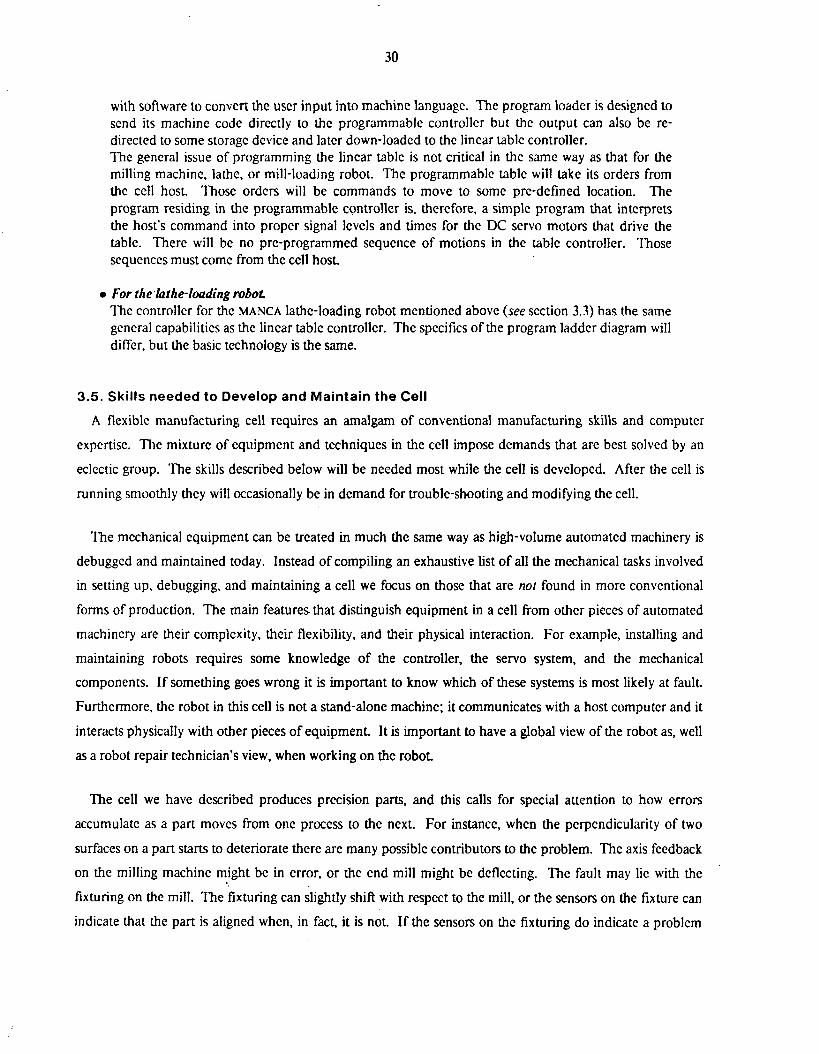
30
with software to convert the user input into machine language. The program loader is designed to send its machine code directly to the programmable controller but the output can also be re- directed to some storage device and later down-loaded to the linear table controller. The general issue of programming the linear table is not critical in the same way as that for the milling machine, lathe, or mill-loading robot. The programmable table will take its orders from the cell host. Those orders will be commands to move to some pre-defined location. The program residing in the programmable controller is. therefore, a simple program that interprets the host’s command into proper signal lcvcls and times for the UC servo motors that drive the table. There will be no pre-programmed sequence of motions in the table controller. ‘Those sequences must come from the cell host.
e For the hthe-loading robot The controller for the MANCA lathe-loading robot mentioned above (see section 3.3) has the same general capabilities as the linear table controller. The specifics of the program ladder diagram will differ, but the basic technology is the same.
3.5. Skills needed to Develop and Maintain the Cell
A flexible manufacturing cell requires an amalgam of conventional manufacturing skills and computer
expertise. The mixture of equipment and techniques in the cell impose demands that are best solved by an
eclectic group. The skills described below will be needed most while the cell is developed. After the cell is
running smoothly they will occasionally be in demand for trouble-shooting and modifying the cell.
The mechanical equipment can be treated in much the same way as high-volume automated machinery is
debugged and maintained today. Instead of compiling an exhaustive list of all the mechanical tasks involved
in setting up, debugging, and maintaining a cell we focus on those that are nul found in more conventional
forms of production. The main features that distinguish equipment in a cell from other pieces of automated
machinery are their complcxity, their flexibility, and their physical interaction. For example, installing and
maintaining robots requires some knowledge of the controller, the servo system, and the mechanical
components. If something goes wrong it is important to know which of these systems is most likely at fault.
Furthermore, the robot in this cell is not a stand-alone machine; it communicates with a host computer and it
interacts physically with other pieces of equipment. It is important to have a global view of the robot as, well
as a robot repair technician’s view, when working on the robot.
The cell we have described produces precision parts, and this calls for special attention to how errors
accumulate as a part moves from one process to the next. For instance, when the perpendicularity of two
surfaces on a part starts to deteriorate there are many possible contributors to the problem. The axis feedback
on the milling machine might be in error, or the end mill might be deflecting. The fault may lie with the
fixturing on the mill. The fixturing can slightly shift with respect to the mill, or the sensors on the fixture can
indicate that the part is aligned when, in fact, it is not. If the sensors on the fixturing do indicate a problem

31
then the robot, or its gripper, may be at fault. The part may be poorly aligned during its acquisition by the
robot. The gripper is equipped with sensors to detect this condition, but they can fail. The possibilities
continue beyond this list. The problem is to find the things which can be re-adjusted to improve the final
accuracy of the p a n Its solution is greatly aided by a thorough understanding of how the processes and
equipment interact. Much of this Understanding will have to be acquired during the initial operation of the
cell.
When the cell is first set up there will be a large amount of mechanical de-bugging to do. The design of
fixtures is expected to be an ongoing and iterative process.
The dcvelopment of the software and hardware to control the cell will require skills that are needed in any
computer environment. The exceptional requirements for an application such as this are centered on the
problem of integrating the computer and the machining worlds. For example, there will be development
problems getting from the cell host into the machine controllers. The creation of the protocols and programs
to achieve this will entail a great deal of initial effort. The effort can be eased by people with skills involving
low-level interfacing of computers. The cell host will have the responsibility of assuring that no un-toward
physical interaction occurs (like the robot running into the mill table). The software to support this duty will
not bc simple and will require the skills of a high-level program designer. The amount of programming to be
done in the cell is large and will require several programmers. The managers for this project will be required
to understand and communicate with people from two very different backgrounds: computers and
machining.
3.6. Problems
Flexible manufacturing cells may be plagued by a number of common problems. Some of these stem from
design errors and are largely avoidable. Others are errors that occur during cell operation and require the
design and implementation of contingency plans.
3.6.1. Design problems
It is unlikely that we can anticipate all of the problems associated with designing a cell but we list a few of the most common design pitfalls below:
0 Flexibility versus Productivity - The components of the cell can be designed to maximize either of these criteria but not both. It is therefore important to decide from a production standpoint how flexible the cell should be and what its productivity should be. All components of the cell should then reflcct this compromise. There is no point in designing extremely adaptable fixturing if the supervisory control system for the cell is not flexible, and vice-versa.
0 Failures - Occasional failures must be anticipated. A machine may fail to operate correctly or a

32
procedure may fail to take place as expected. Failures can result from many causes including equipment breakage, faulty incoming parts and robot drift. I t is probably acccptablc to scrap a part (or in a severe case, a wholc batch of parts) but the equipment in the ccll should not be allowed to seriously damage itself.
0 Critical Items - Evaluate how crucial each component is to the partial operation of the cell. I f the lathe is out of commission then the cell can still do parts that require milling. If one of the robots is out of commission then parts will have to bc fed by hand. I f the supervisory computer is out of commission then the machinc tools and robots can no longer function as a cell. In the case of very critical components, such as the host computer, there should always be spare parts on hand. Sensors, such as limit switches used to detcrmine the presence of a part, should be made redundant so that if one fails then the dcsircd information will still be available.
0 Cell Host Extensibility -- The designers of the cell host will certainly not think of everything the cell "should" do. They will probably avoid doing things that are just plain wrong, but experience in working with the cell will illuminate areas that need additional support. The programs running on the cell host must be easily changed. Their integration into what has been called the cell supervisor must be clear and well structured so individual programs can be easily modified and extended. In particular:
oThere must be a straight-forward procedure for changing the way the cell supervisor sequences the machines in the cell. More than any other operational feature, the sequencing of the machines in the cell will need to be adjusted.
o The understanding of run-time errors will grow (probably exponentially, at first) with experience. The software to handle the errors should be designed to make it straightfornard to add new routines and modify old ones. In addition, the hardware must allow for expansion of the software. A cell host that seems just adequate for the cell at design time will probably soon be bogged down with un-anticipated sensor handling routines.
o The type of data the Supervisor keeps track of will be fairly well understood at design time, but the individual pieces of data almost certainly won't. This is particularly true for the statistical data which is sent to the manufacturing system computer. Additional sampling of random run-time data should be easy to implement.
3.6.2. Runtime problems
Runtime errors will occur in any cell, although they can be reduced by proper design. The cell must be
able to recover from minor errors and must at least be able to avoid damaging itself when confronted with
serious errors. Runtime errors include broken cutting tools, dropped parts, misaligned parts, machine tool
failures and computer crashes. The near-term cell described above is a minimum configuration cell and its
response to most of these errors will be to allow one or more parts to be scrapped. One problem with a
minimum configuration is that the consequences of any given error are more severe for the cell as a whole.
Thus, it is especially important to design durable and perhaps redundant components for the cell.

33
3.7. Alternatives for the Future
The functions and equipment for the ccll described above are by no means exclusive. Various alternative
configurations can be used to increase flexibility -or productivity. For example, the machining cell becomes
considerably more versatile if a four or five axis machining center is uscd in place of a vertical axis CNC mill.
The much greater expense of a machining center is not justified for machining parts from the family typified
by figure 3-1 but it would allow the cell to tackle complex parts that require too many set-ups with a vertical
axis mill or that rcquire contour cutting. As a second example, the lathe could be replaced with a multi-
spindle chucker which would considerably increase the number of turned parts per hour. For many small-
batch precision parts, howevcr, high production volumcs are not an issue.
The way in which the cell locates and then acquires new parts is flexible, but slow. The vision system looks
at each part, determines the coordinates of the part and sends them to the cell host. The cell host then sends
them to the mill-loading robot which carehlly grips the parts and transfers them, one by one, to one of the
machine tools. A faster approach is to use a pallet with fixtures to hold the parts so that they arrive at the cell
with a known orientation. The pallet and cart may be aligned with mechanical locating devices, or the pallet
may be located using the vision system -just once. This approach makes less use of the vision system, and is
less flexible since it presumes that parts are accurately located on the pallet when they arrive. However, if the
parts have arrived from another cell they will have been put down in a systematic and accurate fashion. The
only other requirement is to design the pallet so that the parts do not jostle while they are transported. The
vision system is used only to count the parts, and check that they match the expected description. Even if the
vision systcm is used to establish the position and orientation of parts, it is still advantageous to begin with a
known approximate part orientation. This reduces the likelihood of ambiguous part orientations and can
improve the specd and accuracy of the solution!
The sensors used in the cell could include pressure sensors, force sensors, vibration sensors, and optical
measurement equipment. These devices would allow the cell to check for problems and do some rudimentary
troubleshooting. For example, proportional sensors such as LVDTs or pneumatic gages on the fixtures could
display not only whether parts were aligned but how well they were aligned compared to previous parts in the
batch. Once random noise is filtered out of such measurements, they become very useful in indicating trends
such as a gradual deterioration in robot accuracy or fixture performance. The goal is to discover such trends
before they become a serious problem.
Sensors can also be used to monitor the processes within the cell in an effort to optimize them. For
example, in the machining process one might emulate some of the senscs that an experienced machinist uses
4This technique has been dcmonstrated in recent work by rcsearchers at the University of Rhode Island
34
when running his machine. Thus, in an attempt to automate a machinist's use of tactile feedback,
accelerometers could be mounted in strategic locations on the machine tool to measure the vibration of the
system composed of the machinc tool, fixture and work piece. This information would be used to identify
speeds. fccds, and fixture configurations which maximize chip removal while minimizing vibration. While a
machinist might judge the rate of power consumption of a machinc tool by listening to the spindle drive
motor, a volt meter in combination with an ammeter could measure the drive motor's power consumption.
Checking work picce dimensions, a simple matter of reading a value from a caliper or micrometer for a
machinist, might be accomplished with displacement transducers mounted in specially dcsigncd tool holders.
This, however. has the drawback of being limited by the accuracy of the machine tool itself and occupies the
machine with measurement tasks when it could be cutting metal. ' f i e list can be extended to increasingly
obscure parameters that are normally monitored by a machinist operating a milling machine but un'til better
theoretical modcls of the machining process are available there is little point in monitoring any but the most
basic variables.
The devices mentioned above are more delicate than the simple sensors specified in section 3.3 and they
often require expensive signal processing electronics; but the real reason for not including them in the first
implementation of the flexible cell is that they require sophisticated software support for control and
diagnosis. A considerable amount of research and development would be required to produce such software.
Most of the alternatives to the near-term cell, including those mentioned above in this section, would
increase the first cost of the cell. There are very few alternatives that will decrease the cost of the cell because
a minimum cell configuration has been selected. The one exception to this rule is to wait. We can wait until
machine tools bccomc more flexible, until controllers become more powerful and vcrsatilc, until the software
required for flexible cells is less novel, and then the cost of the cell will go down. Unfortunately if we do wait,
we are no longer building the "Factory of the Future." Also, many of the development costs pertain to the
first cost of thefirsr cell. Once a couple of cells have been built, the development costs become minor.
4. Cell Integration into a Manufacturing System Integrating the cell into a larger manufacturing system is basically a step up the system hierarchy of figure
3-5. Now the problems become ones concerning the cell as a whole (or, to use the earlier lexicon, a module).
This purpose of this section is not to provide a detailed set of guidelines for the system dcsign but to consider
the most important features of the system and to discuss the relationship between the cells and the systcm.
1

35
4.1. System Definition
The system should be usable as a building block for a complete factory. Like the cells beneath it, the
system will be a module with a defined input and output. It will depend on the next higher level of the
hierarchy for certain services such as inventory, engineering support, and scheduling. This division has also
been recently proposed by W. Evcrsheim [Eversheim 821. We expect the system to be semi-autonomous, as
are the cells.
4.2. System Capability
Initially, the manufacturing system may consist ofjust one or two cells but with expansion and flexibility in
mind the initial design should at least have provisions for incorporating the following features:
0The system will monitor material flow within its boundaries. Whether the parts are moved manually or automatically from one cell to the next, the system should be able to keep track them.
0 Information as well as materials will flow from cell to cell. The system will be responsible for coordinating the information passage. For example, when a batch of parts travels from one cell to another it is accompanied by descriptive information. This is done so that the destination cell knows how many parts are in the batch, what their description is, what their orientation is, and so on. At first, information giving the part description and orientation may not be used since the cell program will assume a particular orientation for a particular part type. As cells become more sophisticated they will assume less. Instead, they will rely on their sensors, aided by the information accompanying the parts as they enter the cell.
0 The manufacturing system will store and maintain programs associated with producing the families of parts. In particular:
o The system level computer- will be responsible for maintaining the repertoire of part programs used by CNC machines in the cells.
o Likewise, the cell hosts require a variety of instructions from the system. The sequence programs, for example, for a given part will come from the system level computer.
0 The system will be responsible for maintaining the statistics for the cells and machine tools. These are the usage, maintenance, and history statistics that are necessary for autonomous operation.
0 One of the more important functions of the system level supervisors should be the capability to gracefully degrade the system as individual components fail. The system should also be able to recover from failure when the components are repaired. A thorough discussion of a way to address these issues is given by Fox [Fox 811.
The system may be a very large and versatile collection of cells, but it is not factory. In particular, the
following operations lie berond the scope of the manufacturing system:
0 The retrieval and initial processing of raw materials is done outside the system. For example, the bar stock used for the family of parts discussed in section 3 is usually delivered in 20 foot long

36
sections. Handling these scctions and cutting them to a more manageable size are operations that lie outside the manufacturing system.
0 Inventory and its control are handled outside of the manufacturing system. In-process parts are controlled by the system, but storage of the finished parts and storage of the bar stock and bar stock sections are controlled at the factory level.
0 Maintenance functions required in the factory are not part of the system. These include the maintenance of the the machines, robots, and computers, and also of the software required to run them.
0 The CAD/CAM (Computer Aided DesigrKomputer Aided Manufacturing) system mentioned in section 3.4.2 will reside in computers outside the manufacturing system. The manufacturing system computer will store parts programs and sequence programs but will not be used for designing parts and generating CNC programs.
Figure 4-1 schematically shows the relationship between the manufacturing system and the operations
listed above.
4.3. Modifications at the Cell Level
The modifications to a machining cell that transform it from a solitary, developmental cell into a member
of a manufacturing system are not difficult. The design for the cell specifies input and output for the cell, and
these are services that the manufacturing system provides to the cell. The cell has been designed so that
virtually no modifications in the cell equipment are required. In fact, the performance demanded of
individual machines in a cell may reduce as the number of cells in a manufacturing system increases.
Redundancy makes each piece of equipment less crucial to the function of the system as a whole.
The main modification of the cell will be to the cell host. A communication channel between the
manufacturing system and the cell host must be established. The communication channel will be via the local
network of the factory and the cell host must be given the software and the hardware to use it. The cell host
will receive its instructions and programs from the manufacturing systcm computer instead of its own on-line
storage.
4.4. System Components
The most important components of the manufacturing system are the cells that it comprises, but some
additional components will be needed to tie the cells together:
1
Intercell materials handling devices
The devices responsible for transporting components between the cells in a manufacturing system can take

37
Factory Level Computer Services
Intelligent Management
Computer Aided
Design
Compute r Aided
Manufactu rin!
Management
Manufacturing
Raw Material Handling P roc ess i n g
and Storage
Material Flow Manufacturing
. \/ S!
OIl ci t t Cell
stem
Post-Processing and and Handling
Material Flow
Figure 4-1: A Schematic of the Manufacturing System and the Factory Support Environment
many forms. The traditional conveyor-based systcms are expensive and difficult to maintain. The newer
developments based on robot trucks, for example, also require a large capital investment [Edkins 821. The
success of the system depends most on implementing the cells correctly. Achieving a completcly unmanned
material flow is less important, and initially we allow the handling of materials between the cells to be manual.
To use robot trucks requires not only the very high initial expense of the carts and their guiding apparatus,
I

38
but also the developmcnt of an intelligent, automated system for controlling them, Sensors are required to
keep track of where the individual carts are at any given time, and what parts they are carrying. Batches of
parts will enter or leave the cells only at occasional intervals, so the autonomous nature of the cell and
manufacturing system is not too compromised.
The manufacturing system supervisoiy computer.
The supervisory computer for the manufacturing system will fill much the same role for the system that the
cell host computer does for the cell. A few of the more important chores performed by the system computer
are lister below:
0 Schedule the flow of parts between the cells within the manufacturing system.
0 Direct the flow of information concerning the parts.
0 Store the CNC part programs (for both the CNC machine tools and the robots) in a on-line storage facility.
a Maintain a database that relates particular parts to the programs required to make them.
0 Supply the part programs to the cell host when a new part is sent to a cell.
0 The manufacturing system computer must also provide the cell host with its operating software. If the cell hosts need software support each time they are booted, then the system computer will be responsible for that too.
a ‘ R e statistics arising from the individual cells will need to be compiled, compressed, and analyzed by the manufacturing system computer.
a lhc softwarc for gracefully degrading the system as one or more cells cxpericnce problems will reside in the system computer.
The computer to accomplish thcse functions will need to be a fairly substantial machine. A Digital VAX
11/780, or comparable equipment, should be sufficient for most systems. The computer will be running some
advanced software, so the same caveats apply to this system that apply to the cell host, ie. it should run a good
operating system that can support program and system development.
If there is only one cell, a single computer could act as both the cell host and the manufacturing system
supervisor but there are some arguments against doing this. First, the entire production floor will become
dependent on a single device. Although reliable, today’s computer technology docs fail now and again. Such
a failure could have serious effects on the system productivity. Second, hture expansion will require a
separation of computing power (one machine will not economically support the whole load). Many
headaches can be avoidcd by separating the two supervisors (cell and manufacturing system) from the
39
beginning. And finally, the separated supervisors will be more marketable as separate products. A good cell
host with the proper software is a product not available on today’s market. It should be.
Network links.
The system computer will communicate to the cells over a factory wide network. The technology for Local
Area Networks (LANS) is developing rapidly. Most computer manufacturers are building some sort of
network or interface to an established network. The manufacturing system, the cells and the factory should
capitalize on the new LAN technology.
The Institute of Electrical and Electronic Engineers (IEEE) has established a Committee to propose a
standard for LANs. That committee, the so-called 802 cominittce is now promulgating three preliminary
standards. The third of those, 1 ~ ~ ~ 8 0 2 - 3 , is essentially compatible with the network known as Ethernet
[Shoch 821. The effect of the IEEE proposal will be primarily felt within this country, but the technical press is
mentioning Ethernet as the de facfo standard for LANS [Andrews 82, Koopman 821. In addition to bcing
accepted by the industry, Ethernet is a reasonable networking system. It was developed by Xerox in about
1972[Shoch 821 and is now being marketed by Xerox, Dec, and Intel (primarily). l 3 e factory is a harsh
environment for computer networks, and at least one consortium has implcrnented a fibre-optic version of the
Ethernet [Andrews 821. The optical nature of the transmission medium (the ‘ether’) is much less susceptible
to electromagnetic interference than is the original coax cable.
The hardware and transmission protocols are only part of the networking system, though. The software to
support the LAN at each computer must also exist. Typically, the software to support a complex system lags
the hardware implementations (a truism of software engineering). The software for the Ethernet is well
advanced and will probably be available by the time anyone wants to implement a system such as this.
Another possibility is to use one of the systems which is marketed by a single vendor. DECnet [Wecker 801
and IBM’s SNA (Systems Network Architecture) [Cypser 781 are two examples. The major problem with
such an approach is the restriction to one vendor’s computers for the whole system, or the special
development of interfacing software. Given the wide variety of computers within the manufacturing system
and the even wider variety of tasks, there is much to be said for using a nctwork system that will be a us standard.
The last factor for consideration here is the way the LAN will adapt to the growth of the manufacturing
system. The small manufacturer will probably not invest in a full-blown CAD system until the price drops
considerably. Nonetheless, the original choice for.the LAN should not later restrict the choice of CAD
systems. Similarly, machine tool makers will be implementing links to LANS at some point in the future.

When this occurs, the serial links in the manufacturing cells may be replaccd with a faster LAN scheme,
provided that the LAN originally chosen for the manufacturing systcm is compatible with what thc machine
tool builders offer. The adoption of a US standard is advisable both cases.
5 . Summary The prospects for machining cells and automated manufacturing systems are exciting. If they can be
integrated with factory support tools such as computer aided design and factory management, their power and
utility greatly increase. For the most part, the technology that is used in a truly advanced systcm is available
today. Much work, though, must be done to build the system components and then integrate them into the
system.
We have focused on the design of a cell because a cell illustrates most of the problems involved in
designing an automated factory. We treat it as the fundamental building block for an automated factory. The
cell we describe is a near-term cell -- something one could start to draw the plans for today. Indeed, we
provide the structure for those plans here. The constraint of the near-tern cell, though, forces some
compromises that reduce the sophistication of the cell and keep it from being completely autonomous. The
compromises can be eliminated as more advanced equipment, and some working experience, become
available.
Even a near-term cell requires a few amenities which are not commercially available. The builder of a
semi-automated manufacturing ccll should be prepared for somc development work. The effort is modest
however, and will consist of extensions to currently available hardware and software. The result is a
machining cell that can gracefully grow with the development of new technology in robotics.
6. Acknowledgements An effort to define what should come ahead can only be done with guidance and in an environment that
promotes scholarship and speculative thought. The authors thank Prof. Paul Wright for the former and
gratefully acknowledge Carnegic-Mellon University and the Robotics Institute for the latter.

41
References
[Agin 821
[Anderson 821
[Andrews 821
[Bjorke 791
[Bourne 82a]
[Bourne 82b]
[Bourne 82c]
[Cypser 781
[Edkins 821
Fversheim 82)
Gerald J. Agin. Image Processing Algorithms for Industrial Vision. April 6,1982.
Gordon Anderson and Kenneth Shumate. Selecting a Programming Language, Compiler, and Support Enviroment: Method and
Computer 15(8):29-36, August, 1982. Example.
Warrcn Andrews. Ethernet Seen As LAN Standard. Electronic Engineering Times : 1, September 27, 1982.
0. Bjorke. Computer-Aided Part Manufacturing. Computers in Industry 1:3-9, January, 1979.
D. A. Bourne and P. S. Fussell. Designing Programming Languagesfor h4anufacturing Cells.
Technical Report, The Robotics Institute, Carnegie-Mellon University, April, 1982.
P.K.Wright, D.A.Bourne, R.Milligan. Fault Analysis In A Flexible Manufacturing Cell. Proc. of the 23rd Machine Tool Design & Research ConJ, Manchesrer, England, September,
1982.
David A. Bourne, Robert Milligan Jr., and Paul K. Wright, Fault Detection In Manufacturing Cells Rased on Three Dimensional Visual Information. Proc. Conference of the Internalional Society for Optical Engineering(SPIE), Washington,
DC , May, 1982.
R. J. Cypser. Communications Archilecture for Distributed Systems Addison-Wesley, Reading, Mass, 1978.
M. Edkins, et al. An Evolutionary Flexible Manufacturing Cell. In 14'h Seminar on Manufacturing Cells and Their Subsystems. CIRP -- International
Institution for Production Engineering Research, Faculty Press, Ljubljana, Yogoslavia, June, 1982.
*
W. Evershcim, U. Muller, L. F.Koch. Manufacturing Cells in Unmanned Production. In 14'h Seminar on Manufacturing Cells and Their Subsystems. CIRP -- International
Institution for Production Engineering Research, Faculty Press, Ljubljana, Yogoslavia, June, 1982.

42
[Fox 811 Mark S . Fox. The Inreiligent Mariagernenr Sysrem -- An Overview. Technical Report CMU-RI-TR-81-4, Carnegie Mellon University, l l c Robotics Institute,
August, 1981.
[Gevarter 821 W. B. Gevarter. An Overview of Arlificial Inrelligence and Roborics Volume I I . PB82-204439 NBSlR 82-2479, National Bureau of Standards, March, 1982.
[Gossard 801 D.C. Gossard, D.E. Hardt, F.A. McClintock, B.T. Allison, 1. Gu and K. Stelson. Discrere Die Surface For Sheet Meral Parts. ICAM End of Contract Briefings, Wright-Patterson AFB, January, 1980. .
[Gunn 821 T.G. Gunn. The Mechanizition of Design and Manufacturing. ScientiJic American 247(3): 129, September, 1982.
mouston 81aj G. E. Houston and L. B. Brown. Robotic Sysrern for Aerospace Barch hlanufacruring. Tenth Interim Techical Report IR-812-8(X), McDonnell Douglas Corporation, February,
pages 5.2.1-5.2.6. 1981.
[Houston 81bJ G. E. Houston and L. B. Brown. R obotic Sysrem for Aerospace Barch hl anu facturing. Tenth Interim Techical Report IR-812-8(X), McDonnell Douglas Corporation, February,
pages 5.3.1-5.3.11. 1981.
[Institute 811 M.I. Vuskovic, G. Vitner. A Srudy of Inreractive Control Scheduling and Economic Assessment for Robotic Sysrerns. Final Report NASA-CR-168652, JPL-9950-645, Institute for Technocconomic Systcms,
USC., October, 1981.
[Koopman 821 P Koopman and C Johnson. IEEE-802 is really a Standard. Eleclroriic Engineering Times :66, September 13, 1982.
[Krouse 81) J.K. Krouse. Automated Factories: the Ultimate Union of CAD and CAM. Machine Design 53(27):54-60, November, 1981.
[Merchant 801 M. E. Merchant. The Factory of the Future- Technological Aspects. In L. Kops (editor), Towards [he Facrory ofthe Furure. The American Society of
Mechanical Engineers, United Engineering Center, 345 East 47th Street, New York. NY 10017,1980.
I

43
[Qingsen 821 H. Qingsen. A Linkage Mechanism For The Concentric Gripping of Cylindrical Components. In 12rh Inrernational Symposium on Industrial Robors, pages 401-406. Paris, France, June,
1982.
[Shoch 821 John Shoch, Yogen Dalal, David Redell, Ronald Crane. Evolution of the Ethernet Local Computer Network. Computer 15(8):10-27, August, 1982.
[Syiek 821 David A. Syiek. User's Manual for Versa( 18 August 1982 edition, The Robotics Institute, Carnegie-Mellon University, Pittsburgh,
Pennsylvania 15213,1982.
weck 791 M. Weck, K. Zenner and Y. Tuchelmann. New Developments of Data Processing in Computer Controlled Manufacturing Systems. Sociery of Manufacturing Engineers Technical Paper (MS79-161). 1979.
[Wecker 80) S. Wecker. DNA: thc Digital Newtwork Architecture. IEEE Trans. Communicarions COM-28:510-526, April, 1980.
[Wright 811 P. K. Wright and A. J. Holm. A Programmable Die for the Powder Metallurgy Process. In 91h Norrh American Manufacturing Research Conference at Srare College, PA (NAM RC
IX), pages 65-70. Society of Manufacturing Engineers, Dearborne MI, May, 1981.
Wright 82a) P.K. Wright, D.A. Bourne, J.P. Colyer, G.C. Schatz and J.A.E. Isasi. A Flexible Manufacturing Cell for Swaging. In The I41h CIRP Seminar on Flexible htanufacruring Syslems. Trondheiin, Norway, June,
1982.
[Wright 82b] P.K. Wright and M.R. Cutkosky. Achieving Flexibility in Manufacturing Cells. In to be published in Proceedings. ASME Winter Annual Meeting. Phoenix, AZ, November,
1982.