precise dat400 (3)
TRANSCRIPT

1
PrecisePrecisePrecisePrecise DAT 400 Series
Digital / Analog Transmitters
Installation & Operating Manual
(version 0.7)
9 Richmond St, Picton, ON Canada K0K 2T0Web: www.iwsystems.ca E-Mail [email protected]
Industrial Weighing Systems
Tel: 613-786-0016 Cell: 613-921-0397
2
Technical Specifications
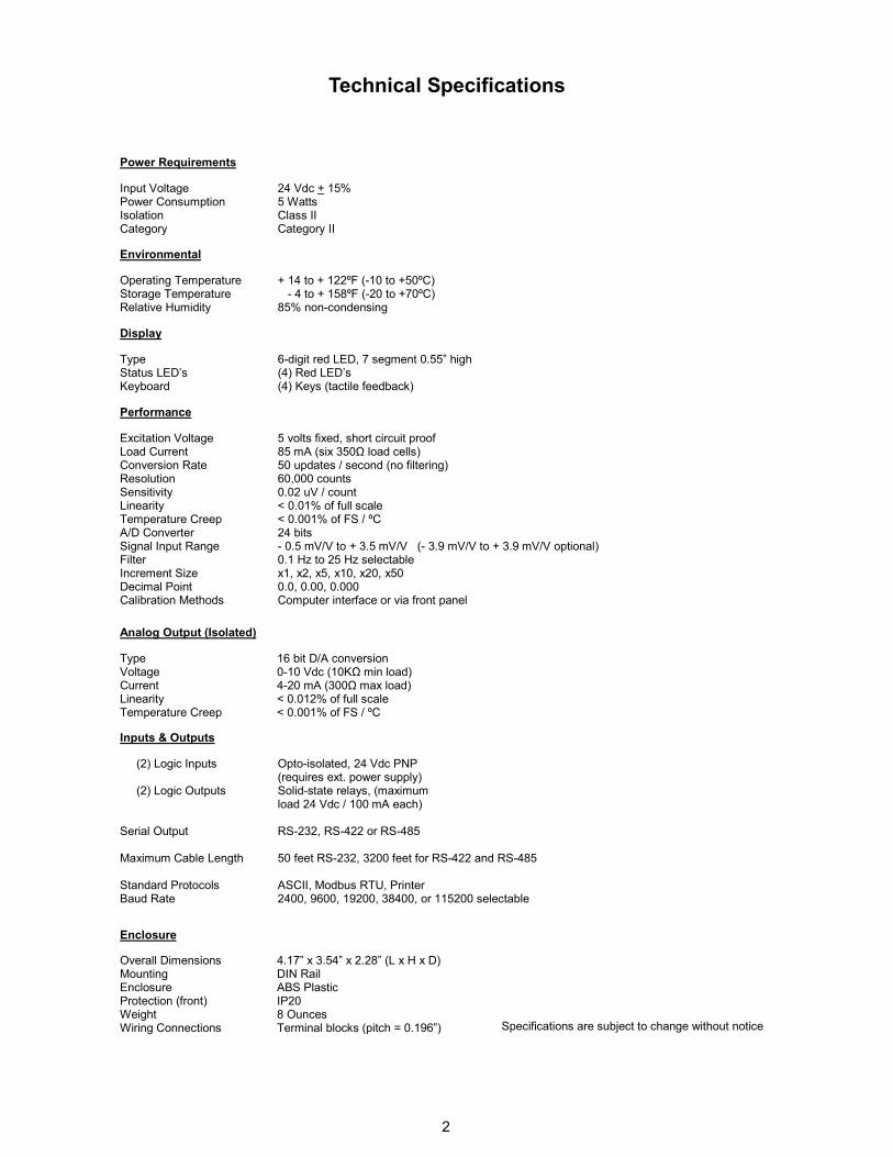
Input Voltage Power Consumption Isolation Category
5 volts fixed, short circuit proof 85 mA (six 350Ω load cells) 50 updates / second (no filtering) 60,000 counts 0.02 uV / count < 0.01% of full scale < 0.001% of FS / ºC 24 bits - 0.5 mV/V to + 3.5 mV/V (- 3.9 mV/V to + 3.9 mV/V optional) 0.1 Hz to 25 Hz selectable x1, x2, x5, x10, x20, x50 0.0, 0.00, 0.000 Computer interface or via front panel
Excitation Voltage Load Current Conversion Rate Resolution Sensitivity Linearity Temperature Creep A/D Converter Signal Input Range Filter Increment Size Decimal Point Calibration Methods
Environmental
Display
Performance
Operating Temperature Storage Temperature Relative Humidity
Type Status LED’s Keyboard
24 Vdc + 15% 5 Watts Class II Category II
+ 14 to + 104ºF (-10 to +40ºC) - 4 to + 122ºF (-20 to +50ºC) 85% non-condensing
6-digit red LED, 7 segment 0.55” high (4) Red LED’s (4) Keys (tactile feedback)
Power Requirements
Type Voltage Current Linearity Temperature Creep
Opto-isolated, 24 Vdc PNP (requires ext. power supply) Solid-state relays, (maximum load 24 Vdc / 100 mA each) RS-232, RS-422 or RS-485 50 feet RS-232, 3200 feet for RS-422 and RS-485 ASCII, Modbus RTU, Printer 2400, 9600, 19200, 38400, or 115200 selectable
Specifications are subject to change without notice
Analog Output (Isolated)
Inputs & Outputs
(2) Logic Inputs (2) Logic Outputs Serial Output Maximum Cable Length
Standard Protocols Baud Rate
Enclosure
Overall Dimensions Mounting Enclosure Protection (front) Weight Wiring Connections
16 bit D/A conversion 0-10 Vdc (10KΩ min load) 4-20 mA (300Ω max load) < 0.012% of full scale < 0.001% of FS / ºC
4.17” x 3.54” x 2.28” (L x H x D) DIN Rail ABS Plastic IP20 8 Ounces Terminal blocks (pitch = 0.196”)
+ 14 to + 122ºF (-10 to +50ºC) - 4 to + 158ºF (-20 to +70ºC) 85% non-condensing

3
Installation
Mounting Install the instrument in a location where it will not be subjected to excessive heat, humidity or vibration. For best results, avoid direct sunlight on the front of the instrument. The unit should be installed at eye level so as to allow viewing the display and access to the front panel keys.
Cable Types and sizes
Use a 6 x 0.5 mm
2 shielded cable for the load
cell/s connection. Use a 3 x 0.34 mm2 shielded
cable for the RS-232 connection, and a 2 x 0.34 mm
2 shielded cable for the RS-485 connection.
Power and Wiring Considerations The instrument is powered from an external 24 Vdc source. The instrument can be operated from a computer, therefore, a “clean” power source is required for reliable operation. The incoming power should come from a source that is isolated from other process equipment. Cables carrying primary and switched power should be routed away from load cell and other signal cables to avoid electrical interference. Relays, motor starters and other inductive devices connected to the equipment must have reliable and effective arc suppression. Always connect the shield lead where indicated on the drawing, and on one end only. High voltage devices such as megohmmeters, etc. should never be used to check the wiring connections. Plastic insulating tape should not be used on load cell connections.
Environmental Considerations Heavy electrical equipment should not be installed close to the weighing equipment. Excessive vibration will affect the accuracy of the weigh system and depending on the severity can cause damage to electrical and electronic components. The atmosphere should be dust free and not contain any corrosive gasses or materials which could adversely affect the equipment.
Hazardous areas If the weighing system will be installed in a hazardous area, please refer to the drawing shown on page 42.
NOTES: WELDING on or in the vicinity of the equipment
is strictly prohibited. STATIC loads, caused by thunderstorms, must be prevented from developing by using reliable lightning conductors. ENSURE that the cooling of the equipment is not obstructed.

4
Introduction
This manual provides general information on the installation, configuration, calibration, and
operation of the Precise 400 Series Digital / Analog Transmitters. There are two models within this series, the Model 400 which features a four-button keyboard, 6-digit Red LED display, and four status LED’s. The Model 450 is a blind unit which can only be configured and calibrated remotely via the serial port. Both models are packaged in ABS Plastic DIN-Rail mounted enclosures.
All units include the following features:
• Drives up to six 350 ohm load cells
• Supports 4 and 6 wire connections
• RS-232, RS-422, or RS-485 outputs
• (2) Logic inputs
• (2) Logic outputs (setpoints)
• Isolated analog output 4/20mA, 0-5 Vdc or 0-10Vdc output utilizing a 16 bit DAC
The Precise 400 Series Transmitters have three different modes of operation:
Operating mode
In this mode the unit displays gross weight, net weight, or peak force readings as required.
Setup mode
This mode is used for configuration and calibration of the unit.
Test mode
The test mode enables you to test the inputs, outputs, and analog output.
Front panel key functions - Operating Mode (Model 400)
The “SET” key enables you to enter values for Setpoints 1 and 2. Press the “SET” key, Set 1 appears on the display. Press the “PRG” key to view the current value. To change the current value, press the “O” key to select a digit, then use the “UP” or “DOWN” keys to increment or decrement the value. Repeat this procedure for the remaining digits, then press the “PRG” key to enter the new value. To change the value for Setpoint 2, press the “SET” key again and repeat the above procedure or press the “O” key to exit.
The “FUN” key is used to switch the unit from Gross mode to Net mode, or Peak Hold mode. To switch to Peak Hold mode, press and hold the “FUN” key until a ‘P’ appears on the display.
Operating Mode (cont’d)
The “O” key is used to zero the unit in Gross mode, tare the unit in Net mode, and reset the value to zero in Peak Hold mode.
The “PRG” key is used to send the data to the RS-232 serial port for use with a computer.
Front panel key functions - Setup Mode
In setup mode three of the front panel keys are used as directional keys to scroll through the various menus. A label on the lower half of each key identifies the direction provided by the key. The “SET” and “FUN” keys are used to navigate through the main menu and sub-menus. They are also used to increment or decrement the numerical value of a selected digit. The “O” key is used to move through certain sub-menu parameters, or to select a specific digit when numerical values are displayed. It is also used to return to the main menu from any of the sub-menus. The “PRG” key switches the unit to the “Basic Configuration” mode. It is also used to enter the sub-menus, and store parameter changes. The “PRG” key when used in conjunction with the “SET” key switches the unit to the “Complete Configuration” mode. It is also used to enter the sub-menus, and store parameter changes.
Status LED’s (Model 400 only)
There are four status LED’s on the front of the unit, one for Motion, one for Net mode, and one for each of the outputs.
Enabling/Disabling front panel keys.
In order to prevent any access to the instrument by non-authorized personnel, a procedure to lock the front panel keys is also available.
Each key can be locked individually. The 1/0 selection establish the lock/unlock condition for each single key.
See page 6 for more details.
Enabling the “blind” function
This function allows to disable the visualization of the display. A dash running counterclockwise on the display’s perimeter is displayed instead of the weight value.
See page 6 for more details.
5
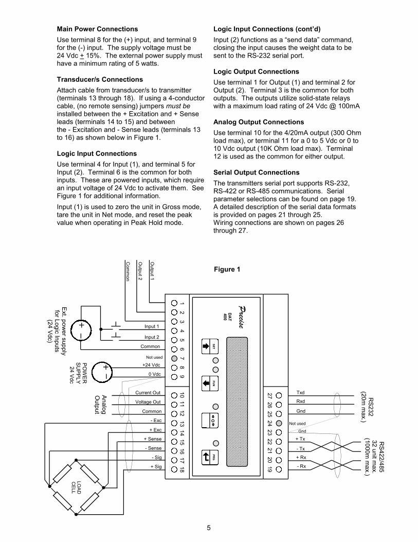
Main Power Connections
Use terminal 8 for the (+) input, and terminal 9 for the (-) input. The supply voltage must be 24 Vdc + 15%. The external power supply must have a minimum rating of 5 watts.
Transducer/s Connections
Attach cable from transducer/s to transmitter (terminals 13 through 18). If using a 4-conductor cable, (no remote sensing) jumpers must be installed between the + Excitation and + Sense leads (terminals 14 to 15) and between the - Excitation and - Sense leads (terminals 13 to 16) as shown below in Figure 1.
Logic Input Connections
Use terminal 4 for Input (1), and terminal 5 for Input (2). Terminal 6 is the common for both inputs. These are powered inputs, which require an input voltage of 24 Vdc to activate them. See Figure 1 for additional information.
Input (1) is used to zero the unit in Gross mode, tare the unit in Net mode, and reset the peak value when operating in Peak Hold mode.
Logic Input Connections (cont’d)
Input (2) functions as a “send data” command, closing the input causes the weight data to be sent to the RS-232 serial port.
Logic Output Connections
Use terminal 1 for Output (1) and terminal 2 for Output (2). Terminal 3 is the common for both outputs. The outputs utilize solid-state relays with a maximum load rating of 24 Vdc @ 100mA
Analog Output Connections
Use terminal 10 for the 4/20mA output (300 Ohm load max), or terminal 11 for a 0 to 5 Vdc or 0 to 10 Vdc output (10K Ohm load max). Terminal 12 is used as the common for either output.
Serial Output Connections
The transmitters serial port supports RS-232, RS-422 or RS-485 communications. Serial parameter selections can be found on page 19. A detailed description of the serial data formats is provided on pages 21 through 25. Wiring connections are shown on pages 26 through 27.
Figure 1
Gnd
Gnd
Not used
Not used
Txd
Rxd
+24 Vdc
0 Vdc
POWER
SUPPLY
24 Vdc
DAT
400
27 26 25 24 23 22 21 20 19
10 11 12 1
3 14 15 16 17 18
FUN
SET
PRG
O
Precise
- Tx
+ Rx
Output 2
Output 1
Input 1
Input 2
Common
Ext. p
ower supply
for Logic Inputs
(24 Vdc)
RS232
(20m max.)
Common
- Exc
+ Exc
+ Sense
- Sense
- Sig
+ Sig
+ Tx
- Rx
RS422/485
32 unit m
ax.
(1000m max.)
Voltage Out
Current Out
Common
Analog
Output
LOAD
CELL
1 2
3 4
5 6
7 8
9
6
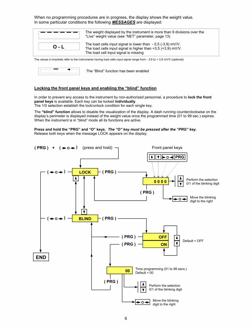
The weight displayed by the instrument is more than 9 divisions over the “Live” weight value (see “NET” parameter, page 13)
The load cells input signal is lower than - 0,5 (-3,9) mV/V. The load cells input signal is higher than +3,5 (+3,9) mV/V. The load cell input signal is missing
O - L
When no programming procedures are in progress, the display shows the weight value.
In some particular conditions the following MESSAGES are displayed:
The values in brackets refer to the instruments having load cells input signal range from - 3,9 to + 3,9 mV/V (optional)
ON
( PRG )
( PRG )
LOCK
O (
(
( PRG ) + (press and hold)
( O
(
0 0 0 0
( PRG )
( PRG )
O
O PRG
Front panel keys
Perform the selection 0/1 of the blinking digit
Move the blinking digit to the right
BLIND
OFF
( PRG ) ( O
(
00
( PRG )
O
Perform the selection 0/1 of the blinking digit
Move the blinking digit to the right
Time programming (01 to 99 secs.) Default = 00
END
The “Blind” function has been enabled
Locking the front panel keys and enabling the “blind” function
In order to prevent any access to the instrument by non-authorized personnel, a procedure to lock the front panel keys is available. Each key can be locked individually. The 1/0 selection establish the lock/unlock condition for each single key.
The “blind” function allows to disable the visualization of the display. A dash running counterclockwise on the display’s perimeter is displayed instead of the weight value once the programmed time (01 to 99 sec.) expires. When the instrument is in “blind” mode all its functions are active.
Press and hold the “PRG” and “O” keys. The “O” key must be pressed after the “PRG” key. Release both keys when the message LOCK appears on the display.
Default = OFF
7
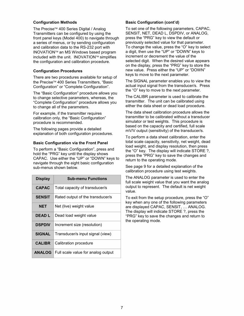
Configuration Methods
The Precise 400 Series Digital / Analog Transmitters can be configured by using the front panel keys (Model 400) to navigate through a series of menus, or by sending configuration and calibration data to the RS-232 port with
INOVATION an MS Windows based program
included with the unit. INOVATION simplifies the configuration and calibration procedure.
Configuration Procedures
There are two procedures available for setup of
the Precise 400 Series Transmitters, “Basic Configuration” or “Complete Configuration”.
The “Basic Configuration” procedure allows you to change selective parameters, whereas, the “Complete Configuration” procedure allows you to change all of the parameters.
For example, if the transmitter requires calibration only, the “Basic Configuration” procedure is recommended.
The following pages provide a detailed explanation of both configuration procedures.
Basic Configuration via the Front Panel
To perform a “Basic Configuration”, press and hold the “PRG” key until the display shows CAPAC. Use either the “UP” or “DOWN” keys to navigate through the eight basic configuration sub-menus shown below.
Basic Configuration (cont’d)
To set one of the following parameters, CAPAC, SENSIT, NET, DEAD L, DSPDIV, or ANALOG, press the “PRG” key to view the default or previously selected value for that parameter. To change the value, press the “O” key to select a digit, then use the “UP” or “DOWN” keys to increment or decrement the value of the selected digit. When the desired value appears on the display, press the “PRG” key to store the new value. Press either the “UP” or “DOWN” keys to move to the next parameter.
The SIGNAL parameter enables you to view the actual input signal from the transducer/s. Press the “O” key to move to the next parameter.
The CALIBR parameter is used to calibrate the transmitter. The unit can be calibrated using either the data sheet or dead load procedure.
The data sheet calibration procedure allows the transmitter to be calibrated without a transducer simulator or test weights. This procedure is based on the capacity and certified, full scale mV/V output (sensitivity) of the transducer/s.
To perform a data sheet calibration, enter the total scale capacity, sensitivity, net weight, dead load weight, and display resolution, then press the “O” key. The display will indicate STORE ?, press the “PRG” key to save the changes and return to the operating mode.
See page 9 for a detailed explanation of the calibration procedure using test weights. The ANALOG parameter is used to enter the full scale weight value that you want the analog output to represent. The default is net weight value.
To exit from the setup procedure, press the “O” key when any one of the following parameters are displayed CAPAC, SENSIT, … ANALOG. The display will indicate STORE ?, press the “PRG” key to save the changes and return to the operating mode.
Display Sub-menu Functions
CAPAC Total capacity of transducer/s
SENSIT Rated output of the transducer/s
NET Net (live) weight value
DEAD L Dead load weight value
DSPDIV Increment size (resolution)
SIGNAL Transducer/s input signal (view)
CALIBR Calibration procedure
ANALOG Full scale value for analog output
8
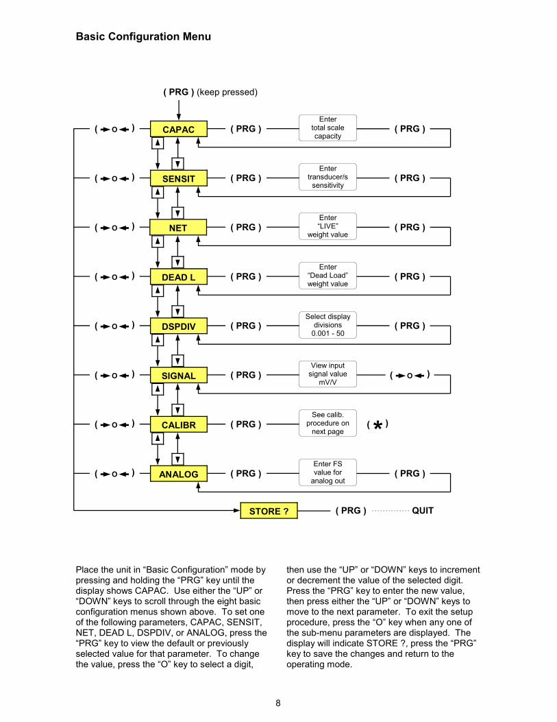
Basic Configuration Menu
Place the unit in “Basic Configuration” mode by pressing and holding the “PRG” key until the display shows CAPAC. Use either the “UP” or “DOWN” keys to scroll through the eight basic configuration menus shown above. To set one of the following parameters, CAPAC, SENSIT, NET, DEAD L, DSPDIV, or ANALOG, press the “PRG” key to view the default or previously selected value for that parameter. To change the value, press the “O” key to select a digit,
then use the “UP” or “DOWN” keys to increment or decrement the value of the selected digit. Press the “PRG” key to enter the new value, then press either the “UP” or “DOWN” keys to move to the next parameter. To exit the setup procedure, press the “O” key when any one of the sub-menu parameters are displayed. The display will indicate STORE ?, press the “PRG” key to save the changes and return to the operating mode.
Enter total scale capacity
Enter transducer/s sensitivity
Enter “LIVE”
weight value
Enter “Dead Load” weight value
Select display divisions 0.001 - 50
View input signal value
mV/V
Enter FS value for analog out
( PRG )
( PRG )
( PRG )
( PRG )
O (
(
( PRG )
( PRG ) (keep pressed)
See calib. procedure on next page
( PRG )
( PRG )
STORE ?
( PRG )
( PRG )
( PRG )
( PRG )
( PRG )
( PRG )
( PRG )
( PRG )
O (
(
O (
(
O (
(
O (
(
O (
(
O (
(
O (
(
O (
(
QUIT
* (
(
SIGNAL
DSPDIV
DEAD L
SENSIT
CAPAC
NET
CALIBR
ANALOG
9
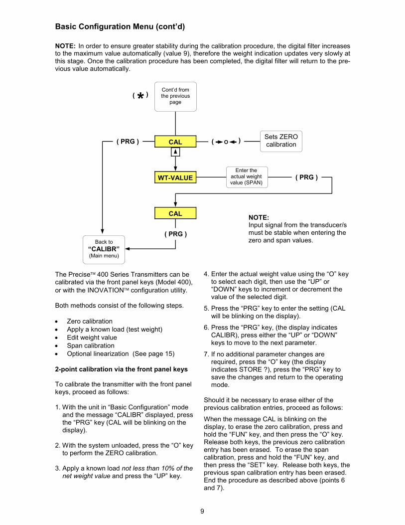
Basic Configuration Menu (cont’d)
The Precise 400 Series Transmitters can be calibrated via the front panel keys (Model 400),
or with the INOVATION configuration utility. Both methods consist of the following steps.
• Zero calibration
• Apply a known load (test weight)
• Edit weight value
• Span calibration
• Optional linearization (See page 15)
2-point calibration via the front panel keys
To calibrate the transmitter with the front panel keys, proceed as follows: 1. With the unit in “Basic Configuration” mode and the message “CALIBR” displayed, press the “PRG” key (CAL will be blinking on the display). 2. With the system unloaded, press the “O” key to perform the ZERO calibration.
3. Apply a known load not less than 10% of the net weight value and press the “UP” key.
4. Enter the actual weight value using the “O” key to select each digit, then use the “UP” or “DOWN” keys to increment or decrement the value of the selected digit.
5. Press the “PRG” key to enter the setting (CAL will be blinking on the display).
6. Press the “PRG” key, (the display indicates CALIBR), press either the “UP” or “DOWN” keys to move to the next parameter.
7. If no additional parameter changes are required, press the “O” key (the display indicates STORE ?), press the “PRG” key to save the changes and return to the operating mode. Should it be necessary to erase either of the previous calibration entries, proceed as follows:
When the message CAL is blinking on the display, to erase the zero calibration, press and hold the “FUN” key, and then press the “O” key. Release both keys, the previous zero calibration entry has been erased. To erase the span calibration, press and hold the “FUN” key, and then press the “SET” key. Release both keys, the previous span calibration entry has been erased. End the procedure as described above (points 6 and 7).
NOTE: Input signal from the transducer/s must be stable when entering the zero and span values.
CAL
WT-VALUE
CAL
Sets ZERO calibration
Enter the actual weight value (SPAN)
Back to
“CALIBR” (Main menu)
( PRG )
( PRG )
Cont’d from the previous
page
NOTE: In order to ensure greater stability during the calibration procedure, the digital filter increases to the maximum value automatically (value 9), therefore the weight indication updates very slowly at this stage. Once the calibration procedure has been completed, the digital filter will return to the pre-vious value automatically.
O (
(
* (
(
( PRG )
10
Configuration using INOVATION
To configure the Precise 400 Series Digital /
Analog Transmitters with the INOVATION program, proceed as follows:
1. Install INOVATION on an IBM-compatible computer running Windows 95, 98, Me or XP.
2. Minimum system requirements are 8MB of extended memory and at least 5MB of available hard drive space.
3. Remove power from both units, and connect the PC’s serial port to the RS-232 terminals on the transmitter. Refer to page 27 for wiring.
4. Apply power to the PC and the transmitter,
then start the INOVATION program.
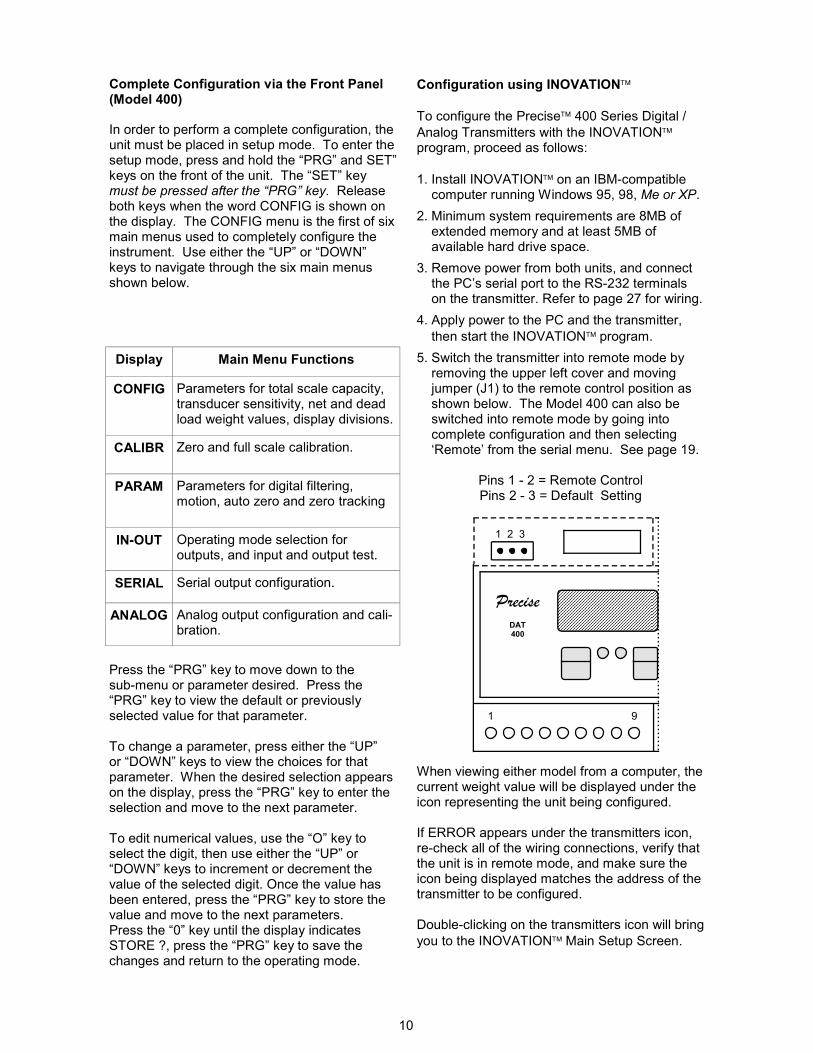
5. Switch the transmitter into remote mode by removing the upper left cover and moving jumper (J1) to the remote control position as shown below. The Model 400 can also be switched into remote mode by going into complete configuration and then selecting ‘Remote’ from the serial menu. See page 19.
Pins 1 - 2 = Remote Control Pins 2 - 3 = Default Setting
When viewing either model from a computer, the current weight value will be displayed under the icon representing the unit being configured. If ERROR appears under the transmitters icon, re-check all of the wiring connections, verify that the unit is in remote mode, and make sure the icon being displayed matches the address of the transmitter to be configured. Double-clicking on the transmitters icon will bring
you to the INOVATION Main Setup Screen.
Display Main Menu Functions
CONFIG Parameters for total scale capacity, transducer sensitivity, net and dead load weight values, display divisions.
CALIBR Zero and full scale calibration.
PARAM Parameters for digital filtering, motion, auto zero and zero tracking
IN-OUT Operating mode selection for outputs, and input and output test.
SERIAL Serial output configuration.
ANALOG Analog output configuration and cali-bration.
Complete Configuration via the Front Panel(Model 400) In order to perform a complete configuration, the unit must be placed in setup mode. To enter the setup mode, press and hold the “PRG” and SET” keys on the front of the unit. The “SET” key must be pressed after the “PRG” key. Release both keys when the word CONFIG is shown on the display. The CONFIG menu is the first of six main menus used to completely configure the instrument. Use either the “UP” or “DOWN” keys to navigate through the six main menus shown below.
Press the “PRG” key to move down to the sub-menu or parameter desired. Press the “PRG” key to view the default or previously selected value for that parameter. To change a parameter, press either the “UP” or “DOWN” keys to view the choices for that parameter. When the desired selection appears on the display, press the “PRG” key to enter the selection and move to the next parameter. To edit numerical values, use the “O” key to select the digit, then use either the “UP” or “DOWN” keys to increment or decrement the value of the selected digit. Once the value has been entered, press the “PRG” key to store the value and move to the next parameters. Press the “0” key until the display indicates STORE ?, press the “PRG” key to save the changes and return to the operating mode.
DAT 400
1 2 3
1 9
Precise
11
Configuration using INOVATION (cont’d)
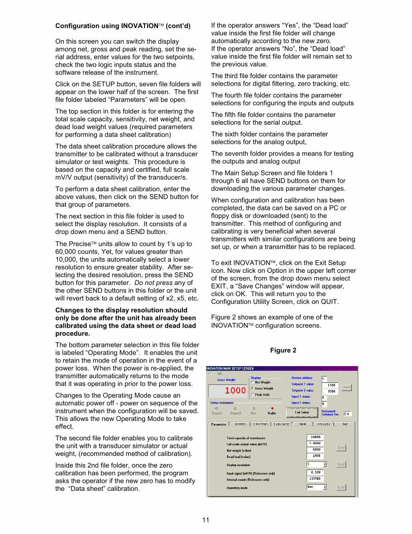
On this screen you can switch the display among net, gross and peak reading, set the se-rial address, enter values for the two setpoints, check the two logic inputs status and the software release of the instrument.
Click on the SETUP button, seven file folders will appear on the lower half of the screen. The first file folder labeled “Parameters” will be open.
The top section in this folder is for entering the total scale capacity, sensitivity, net weight, and dead load weight values (required parameters for performing a data sheet calibration)
The data sheet calibration procedure allows the transmitter to be calibrated without a transducer simulator or test weights. This procedure is based on the capacity and certified, full scale mV/V output (sensitivity) of the transducer/s.
To perform a data sheet calibration, enter the above values, then click on the SEND button for that group of parameters.
The next section in this file folder is used to select the display resolution. It consists of a drop down menu and a SEND button.
The Precise units allow to count by 1’s up to 60,000 counts, Yet, for values greater than 10,000, the units automatically select a lower resolution to ensure greater stability. After se-lecting the desired resolution, press the SEND button for this parameter. Do not press any of the other SEND buttons in this folder or the unit will revert back to a default setting of x2, x5, etc.
Changes to the display resolution should only be done after the unit has already been calibrated using the data sheet or dead load procedure.
The bottom parameter selection in this file folder is labeled “Operating Mode”. It enables the unit to retain the mode of operation in the event of a power loss. When the power is re-applied, the transmitter automatically returns to the mode that it was operating in prior to the power loss.
Changes to the Operating Mode cause an automatic power off - power on sequence of the instrument when the configuration will be saved. This allows the new Operating Mode to take effect.
The second file folder enables you to calibrate the unit with a transducer simulator or actual weight, (recommended method of calibration).
Inside this 2nd file folder, once the zero calibration has been performed, the program asks the operator if the new zero has to modify the “Data sheet” calibration.
Figure 2
If the operator answers “Yes”, the “Dead load” value inside the first file folder will change automatically according to the new zero. If the operator answers “No”, the “Dead load” value inside the first file folder will remain set to the previous value.
The third file folder contains the parameter selections for digital filtering, zero tracking, etc.
The fourth file folder contains the parameter selections for configuring the inputs and outputs
The fifth file folder contains the parameter selections for the serial output.
The sixth folder contains the parameter selections for the analog output,
The seventh folder provides a means for testing the outputs and analog output
The Main Setup Screen and file folders 1 through 6 all have SEND buttons on them for downloading the various parameter changes.
When configuration and calibration has been completed, the data can be saved on a PC or floppy disk or downloaded (sent) to the transmitter. This method of configuring and calibrating is very beneficial when several transmitters with similar configurations are being set up, or when a transmitter has to be replaced.
To exit INOVATION, click on the Exit Setup icon. Now click on Option in the upper left corner of the screen, from the drop down menu select EXIT, a “Save Changes” window will appear, click on OK. This will return you to the Configuration Utility Screen, click on QUIT. Figure 2 shows an example of one of the
INOVATION configuration screens.
12
Figure 2.1
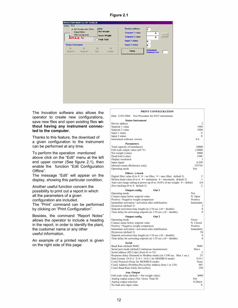
The Inovation software also allows the operator to create new configurations,
save new files and open existing files wi-thout having any instrument connec-ted to the computer.
Thanks to this feature, the download of a given configuration to the instrument can be performed at any time.
To perform the operation mentioned above click on the “Edit” menu at the left end upper corner (See figure 2.1), then enable the function “Edit Configuration Offline”. The message “Edit” will appear on the display, showing this particular condition.
Another useful function concern the possibility to print out a report in which all the parameters of a given configuration are included. The “Print” command can be performed by clicking on “Print Configuration”.
Besides, the command “Report Notes” allows the operator to include a heading in the report, in order to identify the plant, the customer name or any other useful information.
An example of a printed report is given on the right side of this page:
PRINT CONFIGURATION
Date 12/01/2004 Test Procedure for DAT instruments
Status Instrument
Device address 2
Setpoint 1 value 1500
Setpoint 2 value 3500
Input 1 status 0
Input 2 status 0
Instrument software version 0.4
Parameters
Total capacity of transducers 10000
Full scale output value (mV/V) 2.0000
Net weight (value) 8000
Dead load (value) 1500
Display resolution 1
Input signal 0.599
Internal counts (Reference only) 155729
Operating mode Net
Filters / z-track
Digital filter value (0 to 9: 0 = no filter; 9 = max filter; default 5) 5
Motion band value (0 to 4: 0 = minimum; 4 = maximum; default 2) 1
Auto zero range setting at power up (0 to 10.0% of net weight: 0 = disble) 0.0
Zero tracking (0 to 4: default 2) 2
Output config. Out 1
Operating mode Net
Contact status below setpoint value N. Open
Positive / Negative weight comparison Positive
Immediate activation / activation after stabilization Immediate
Hysteresis (default 2) 2
Setpoint activation time length (in 1/10 sec.) (0 = disable) 0
Time delay for activating setpoint (in 1/10 sec.) (0 = disable) 0
Output config. Out 2
Operating mode Gross
Contact status below setpoint value N. Closed
Positive / Negative weight comparison Positive
Immediate activation / activation after stabilization Immediate
Hysteresis (default 2) 50
Setpoint activation time length (in 1/10 sec.) (0 = disable) 0
Time delay for activating setpoint (in 1/10 sec.) (0 = disable) 0
Serial
Baud Rate (default 9600) 9600
Serial port mode (default Continuous transmission) Slave
Serial address (ID Code) (from 01 to 32) 2
Response delay (Demand or Modbus mode) (in 1/100 sec. Max 1 sec.) 25
Data Format (N-8-2 / E-8-1 / O-8-1 for MODBUS mode) N-8-1
Com2 Protocol (None for MODBUS mode) None
Com2 Address (Profibus/DeviceNet Address from 1 to 126) 001
Com2 Baud Rate (Only DeviceNet) 250
Ana. Output
Full scale value (default = Net weight value) 8000
Analog output source (Net Gross Peak H) Net
Analog output selection 0-20mA
No load zero input value 0
13
Complete Configuration Menu
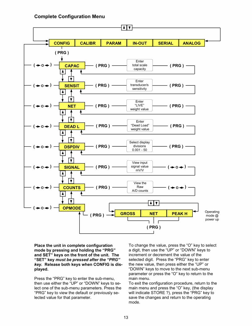
Place the unit in complete configuration mode by pressing and holding the “PRG” and SET” keys on the front of the unit. The “SET” key must be pressed after the “PRG” key. Release both keys when CONFIG is dis-played. Press the “PRG” key to enter the sub-menu, then use either the “UP” or “DOWN” keys to se-lect one of the sub-menu parameters. Press the “PRG” key to view the default or previously se-lected value for that parameter.
To change the value, press the “O” key to select a digit, then use the “UP” or “DOWN” keys to increment or decrement the value of the selected digit. Press the “PRG” key to enter the new value, then press either the “UP” or “DOWN” keys to move to the next sub-menu parameter or press the “O” key to return to the main menu. To exit the configuration procedure, return to the main menu and press the “O” key, (the display will indicate STORE ?), press the “PRG” key to save the changes and return to the operating mode.
CALIBR PARAM IN-OUT SERIAL ANALOG
SENSIT
NET
DEAD L
SIGNAL
Operating mode @ power up
( PRG )
( PRG )
CONFIG
Enter total scale capacity
( PRG ) ( PRG )
Enter transducer/s sensitivity
( PRG ) ( PRG )
Enter “LIVE”
weight value ( PRG ) ( PRG )
Enter “Dead Load” weight value
( PRG ) ( PRG )
Select display divisions 0.001 - 50
( PRG ) ( PRG ) DSPDIV
View input signal value
mV/V O (
(
( PRG )
View the Raw
A/D counts O (
(
( PRG ) COUNTS
GROSS
OPMODE
NET PEAK H
( PRG )
CAPAC O (
(
O (
(
O (
(
O (
(
O (
(
O (
(
O (
(
O (
(
14
Complete Configuration Menu (cont’d)
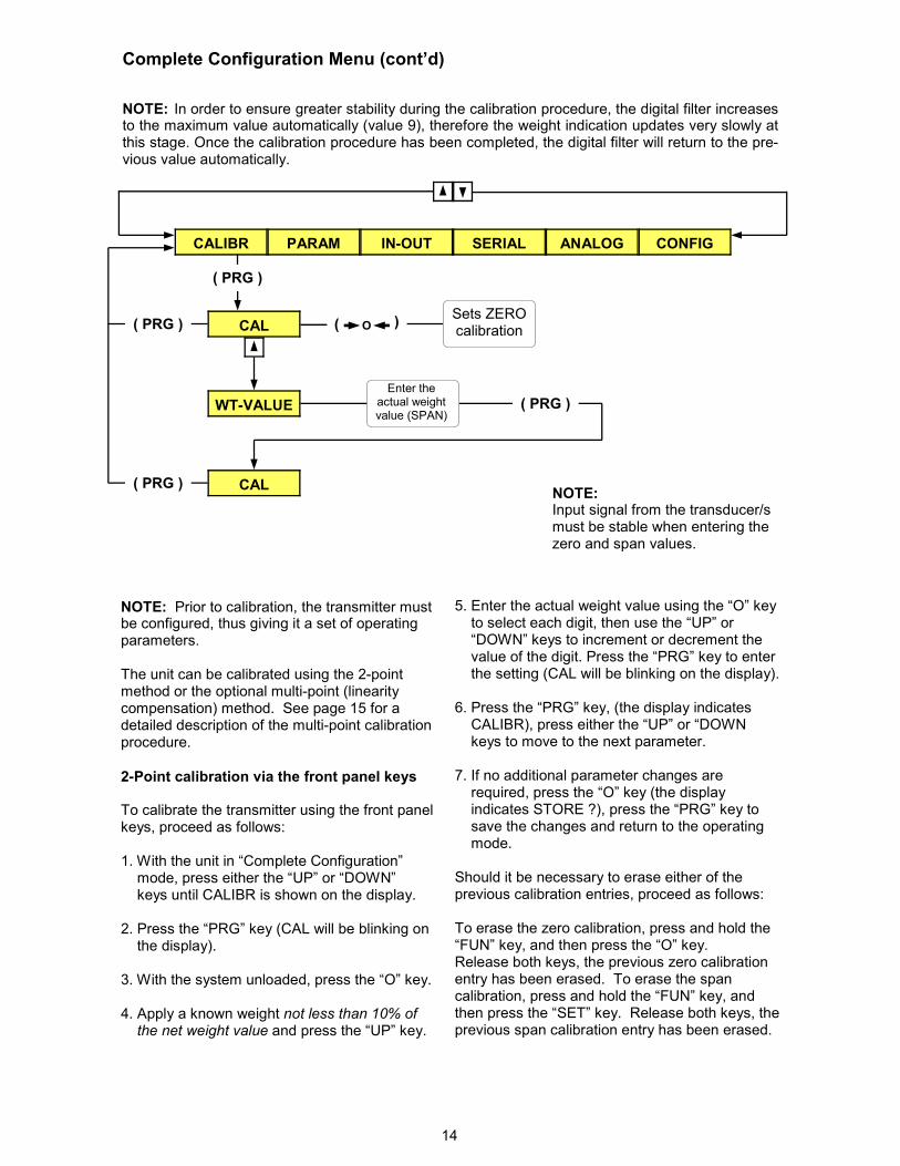
NOTE: Prior to calibration, the transmitter must be configured, thus giving it a set of operating parameters. The unit can be calibrated using the 2-point method or the optional multi-point (linearity compensation) method. See page 15 for a detailed description of the multi-point calibration procedure.
2-Point calibration via the front panel keys
To calibrate the transmitter using the front panel keys, proceed as follows: 1. With the unit in “Complete Configuration” mode, press either the “UP” or “DOWN” keys until CALIBR is shown on the display. 2. Press the “PRG” key (CAL will be blinking on the display). 3. With the system unloaded, press the “O” key. 4. Apply a known weight not less than 10% of the net weight value and press the “UP” key.
5. Enter the actual weight value using the “O” key to select each digit, then use the “UP” or “DOWN” keys to increment or decrement the value of the digit. Press the “PRG” key to enter the setting (CAL will be blinking on the display). 6. Press the “PRG” key, (the display indicates CALIBR), press either the “UP” or “DOWN keys to move to the next parameter. 7. If no additional parameter changes are required, press the “O” key (the display indicates STORE ?), press the “PRG” key to save the changes and return to the operating mode. Should it be necessary to erase either of the previous calibration entries, proceed as follows: To erase the zero calibration, press and hold the “FUN” key, and then press the “O” key. Release both keys, the previous zero calibration entry has been erased. To erase the span calibration, press and hold the “FUN” key, and then press the “SET” key. Release both keys, the previous span calibration entry has been erased.
PARAM IN-OUT SERIAL ANALOG CONFIG
NOTE: Input signal from the transducer/s must be stable when entering the zero and span values.
CAL
WT-VALUE
CAL
Sets ZERO calibration
Enter the actual weight value (SPAN)
( PRG )
NOTE: In order to ensure greater stability during the calibration procedure, the digital filter increases to the maximum value automatically (value 9), therefore the weight indication updates very slowly at this stage. Once the calibration procedure has been completed, the digital filter will return to the pre-vious value automatically.
O (
(
( PRG )
( PRG )
CALIBR
( PRG )
15
Complete Configuration Menu (cont’d)
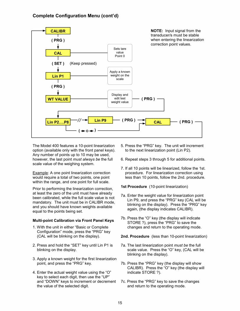
The Model 400 features a 10-point linearization option (available only with the front panel keys). Any number of points up to 10 may be used, however, the last point must always be the full scale value of the weighing system. Example: A one point linearization correction would require a total of two points, one point within the range, and one point for full scale.
Prior to performing the linearization correction, at least the zero of the unit must have already been calibrated, while the full scale value is not mandatory. The unit must be in CALIBR mode, and you should have known weights available equal to the points being set.
Multi-point Calibration via Front Panel Keys
1. With the unit in either “Basic or Complete Configuration” mode, press the “PRG” key (CAL will be blinking on the display). 2. Press and hold the “SET” key until Lin P1 is blinking on the display. 3. Apply a known weight for the first linearization point, and press the “PRG” key. 4. Enter the actual weight value using the “O” key to select each digit, then use the “UP” and “DOWN” keys to increment or decrement the value of the selected digit.
5. Press the “PRG” key. The unit will increment to the next linearization point (Lin P2). 6. Repeat steps 3 through 5 for additional points. 7. If all 10 points will be linearized, follow the 1st. procedure. For linearization correction using less than 10 points, follow the 2nd. procedure.
1st Procedure (10-point linearization) 7a. Enter the weight value for linearization point Lin P9, and press the “PRG” key (CAL will be blinking on the display). Press the “PRG” key again, (the display indicates CALIBR). 7b. Press the “O” key (the display will indicate STORE ?), press the “PRG” to save the changes and return to the operating mode.
2nd. Procedure (less than 10-point linearization) 7a. The last linearization point must be the full scale value. Press the “O” key, (CAL will be blinking on the display). 7b. Press the “PRG” key (the display will show CALIBR). Press the “O” key (the display will indicate STORE ?). 7c. Press the “PRG” key to save the changes and return to the operating mode.
Lin P1
Sets tare value Point 0
Lin P9
Display and edit test
weight value
NOTE: Input signal from the transducer/s must be stable when entering the linearization correction point values.
CAL
( PRG )
CALIBR
( SET ) (Keep pressed)
Apply a known weight on the
scale
( PRG )
WT VALUE ( PRG )
Lin P2….P8 ( PRG )
CAL ( PRG )
O (
(
16
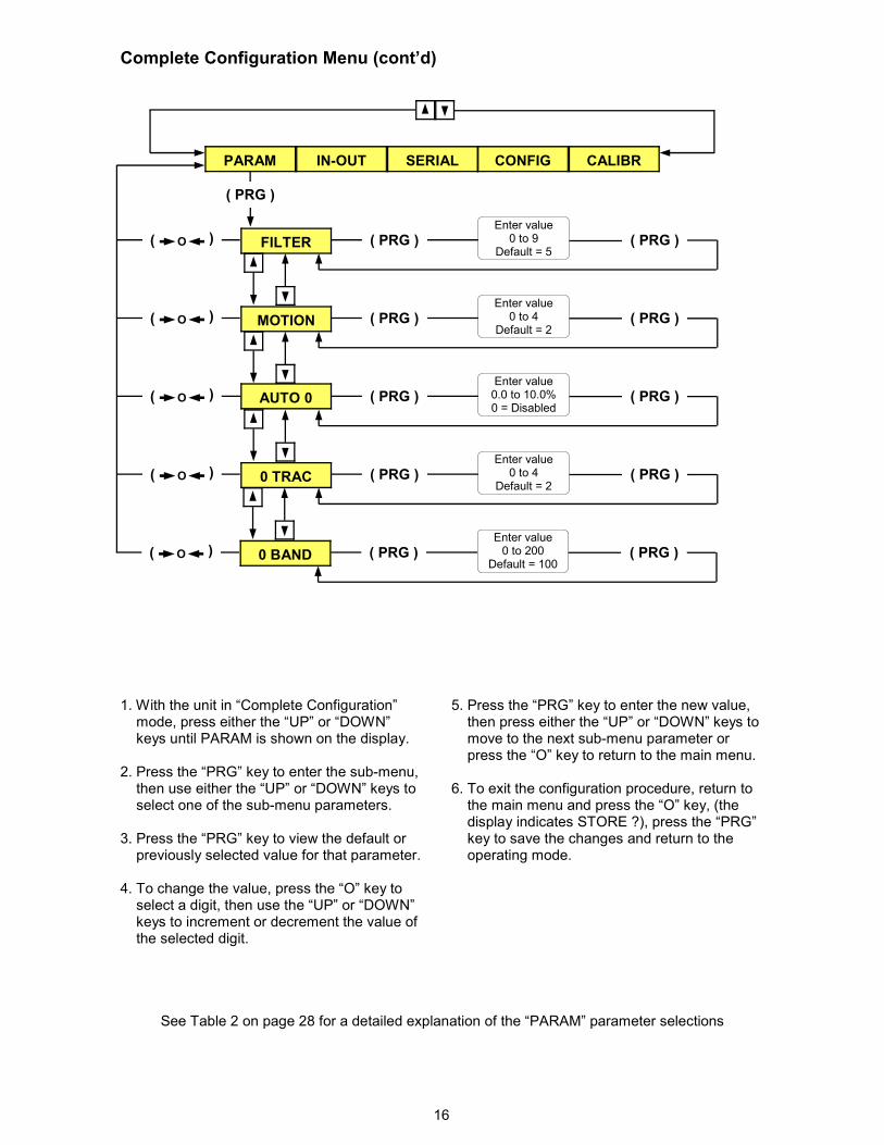
Complete Configuration Menu (cont’d)
1. With the unit in “Complete Configuration” mode, press either the “UP” or “DOWN” keys until PARAM is shown on the display. 2. Press the “PRG” key to enter the sub-menu, then use either the “UP” or “DOWN” keys to select one of the sub-menu parameters. 3. Press the “PRG” key to view the default or previously selected value for that parameter. 4. To change the value, press the “O” key to select a digit, then use the “UP” or “DOWN” keys to increment or decrement the value of the selected digit.
5. Press the “PRG” key to enter the new value, then press either the “UP” or “DOWN” keys to move to the next sub-menu parameter or press the “O” key to return to the main menu. 6. To exit the configuration procedure, return to the main menu and press the “O” key, (the display indicates STORE ?), press the “PRG” key to save the changes and return to the operating mode.
See Table 2 on page 28 for a detailed explanation of the “PARAM” parameter selections
PARAM IN-OUT SERIAL CONFIG CALIBR
FILTER
MOTION
AUTO 0
0 TRAC
Enter value 0 to 4
Default = 2
Enter value 0 to 9
Default = 5
Enter value 0.0 to 10.0% 0 = Disabled
Enter value 0 to 4
Default = 2
( PRG )
( PRG ) ( PRG )
( PRG ) ( PRG )
( PRG ) ( PRG )
( PRG ) ( PRG )
O (
(
O (
(
O (
(
O (
(
0 BAND
Enter value 0 to 200
Default = 100 ( PRG ) ( PRG ) O (
(
17
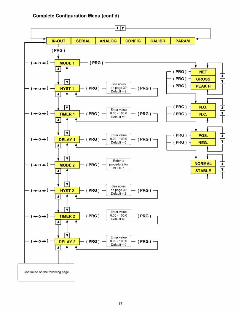
Complete Configuration Menu (cont’d)
MODE 1
IN-OUT SERIAL ANALOG CONFIG CALIBR PARAM
( PRG )
( PRG )
( PRG )
( PRG )
( PRG )
NET
GROSS
PEAK H
( PRG )
( PRG )
N.O.
N.C.
( PRG )
( PRG ) NEG.
POS.
NORMAL
STABLE
HYST 1 ( PRG ) ( PRG ) See notes on page 30 Default = 2
TIMER 1
Enter value 0.00 - 100.0 Default = 0
( PRG ) ( PRG )
DELAY 1
Enter value 0.00 - 100.0 Default = 0
( PRG ) ( PRG )
HYST 2 ( PRG ) ( PRG ) See notes on page 30 Default = 2
TIMER 2
Enter value 0.00 - 100.0 Default = 0
( PRG ) ( PRG )
MODE 2
Refer to procedure for MODE 1
( PRG )
DELAY 2
Enter value 0.00 - 100.0 Default = 0
( PRG ) ( PRG )
O (
(
O (
(
O (
(
O (
(
O (
(
O (
(
O (
(
O (
(
Continued on the following page
18
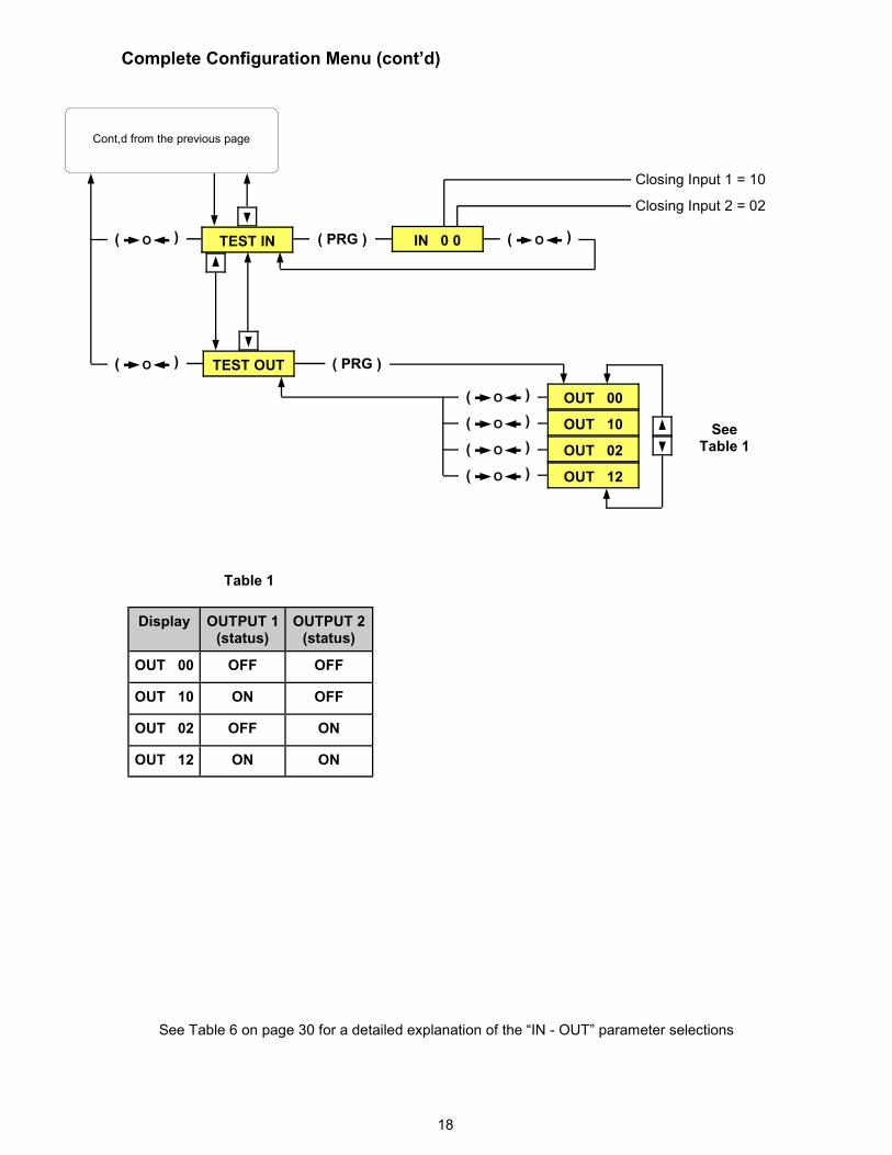
Complete Configuration Menu (cont’d)
TEST OUT
See Table 1
Display OUTPUT 1 (status)
OUTPUT 2 (status)
OUT 00 OFF OFF
OUT 10 ON OFF
OUT 02 OFF ON
OUT 12 ON ON
Table 1
See Table 6 on page 30 for a detailed explanation of the “IN - OUT” parameter selections
IN 0 0
Closing Input 2 = 02
Closing Input 1 = 10
O (
(
( PRG )
Cont,d from the previous page
O (
(
TEST IN
( PRG )
OUT 00
OUT 10
OUT 02
OUT 12
O (
(
O (
(
O (
(
O (
(
O (
(
19
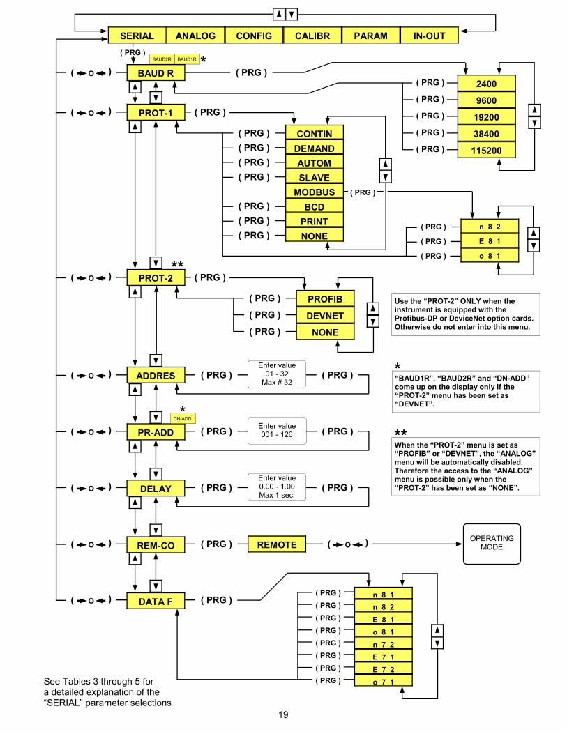
**
DEVNET
CONFIG CALIBR PARAM IN-OUT
BAUD R 2400
9600
19200
38400
PROT-1
ADDRES
DELAY
CONTIN
DEMAND
AUTOM
SLAVE
MODBUS
BCD
NONE
O (
(
See Tables 3 through 5 for a detailed explanation of the “SERIAL” parameter selections
REM-CO REMOTE OPERATING
MODE
115200
( PRG )
( PRG )
( PRG )
( PRG )
( PRG )
( PRG )
( PRG )
( PRG )
( PRG )
( PRG )
( PRG )
( PRG )
Enter value 01 - 32 Max # 32
Enter value 0.00 - 1.00 Max 1 sec.
( PRG ) ( PRG )
( PRG ) ( PRG )
( PRG )
O (
(
O (
(
O (
(
O (
(
O (
(
PROT-2
NONE
( PRG )
( PRG )
( PRG )
( PRG ) O (
(
PROFIB
PR-ADD Enter value 001 - 126 ( PRG ) ( PRG ) O (
(
*
Use the “PROT-2” ONLY when the instrument is equipped with the Profibus-DP or DeviceNet option cards. Otherwise do not enter into this menu.
“BAUD1R”, “BAUD2R” and “DN-ADD” come up on the display only if the “PROT-2” menu has been set as “DEVNET”.
** When the “PROT-2” menu is set as “PROFIB” or “DEVNET”, the “ANALOG” menu will be automatically disabled. Therefore the access to the “ANALOG” menu is possible only when the “PROT-2” has been set as “NONE”.
* DN-ADD
* BAUD1R
( PRG )
n 8 2
E 8 1
o 8 1
( PRG )
( PRG )
( PRG )
SERIAL ANALOG
( PRG )
( PRG ) BAUD2R
n 8 1
n 8 2
E 8 1
o 8 1
n 7 2
E 7 1
E 7 2
o 7 1
DATA F ( PRG ) O (
( ( PRG )
( PRG )
( PRG )
( PRG )
( PRG )
( PRG )
( PRG )
( PRG )
( PRG )
20
Complete Configuration Menu (cont’d)
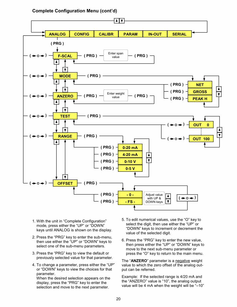
1. With the unit in “Complete Configuration” mode, press either the “UP” or “DOWN” keys until ANALOG is shown on the display.
2. Press the “PRG” key to enter the sub-menu, then use either the “UP” or “DOWN” keys to select one of the sub-menu parameters.
3. Press the “PRG” key to view the default or previously selected value for that parameter.
4. To change a parameter, press either the “UP” or “DOWN” keys to view the choices for that parameter. When the desired selection appears on the display, press the “PRG” key to enter the selection and move to the next parameter.
5. To edit numerical values, use the “O” key to select the digit, then use either the “UP” or “DOWN” keys to increment or decrement the value of the selected digit.
6. Press the “PRG” key to enter the new value, then press either the “UP” or “DOWN” keys to move to the next sub-menu parameter or press the “O” key to return to the main menu.
The “ANZERO” parameter is a negative weight value to which the zero offset of the analog out-put can be referred.
Example: If the selected range is 4/20 mA and the “ANZERO” value is “10”, the analog output value will be 4 mA when the weight will be “–10”
ANALOG CONFIG CALIBR PARAM IN-OUT SERIAL
F-SCAL
MODE
TEST
OFFSET
Enter weight value
( PRG )
Enter span value ( PRG ) ( PRG )
( PRG )
( PRG )
( PRG )
( PRG )
NET
GROSS
PEAK H ANZERO ( PRG ) ( PRG )
( PRG )
OUT 0
OUT 100
O (
(
O (
( RANGE
( PRG )
( PRG )
( PRG )
0-20 mA
4-20 mA
0-10 V
( PRG )
( PRG ) 0-5 V
( PRG )
( PRG )
- 0 -
- FS -
( PRG )
Adjust value with UP & DOWN keys
O (
(
O (
(
O (
(
O (
(
O (
(
O (
(
O (
(
21
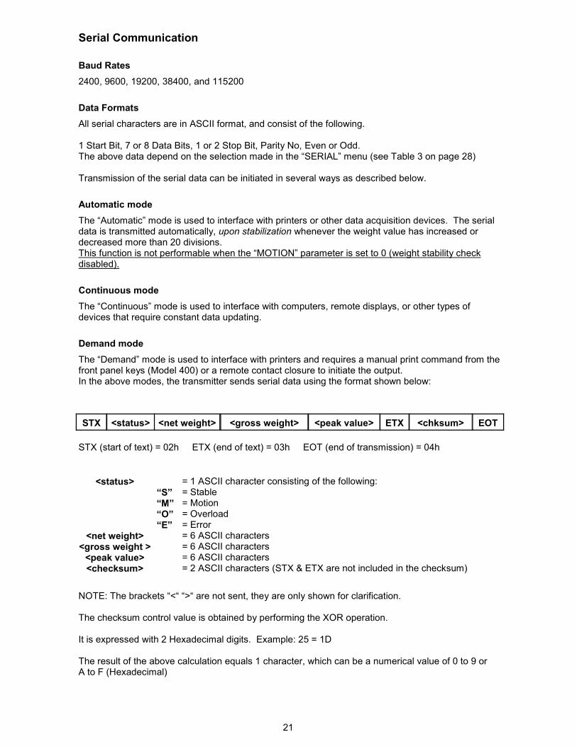
Baud Rates
2400, 9600, 19200, 38400, and 115200
Data Formats
All serial characters are in ASCII format, and consist of the following. 1 Start Bit, 7 or 8 Data Bits, 1 or 2 Stop Bit, Parity No, Even or Odd. The above data depend on the selection made in the “SERIAL” menu (see Table 3 on page 28)
Transmission of the serial data can be initiated in several ways as described below.
Automatic mode
The “Automatic” mode is used to interface with printers or other data acquisition devices. The serial data is transmitted automatically, upon stabilization whenever the weight value has increased or decreased more than 20 divisions. This function is not performable when the “MOTION” parameter is set to 0 (weight stability check disabled).
Continuous mode
The “Continuous” mode is used to interface with computers, remote displays, or other types of devices that require constant data updating.
Demand mode
The “Demand” mode is used to interface with printers and requires a manual print command from the front panel keys (Model 400) or a remote contact closure to initiate the output. In the above modes, the transmitter sends serial data using the format shown below:
Serial Communication
STX <status> <net weight> <gross weight> <peak value> ETX <chksum> EOT
STX (start of text) = 02h ETX (end of text) = 03h EOT (end of transmission) = 04h
NOTE: The brackets “<“ “>“ are not sent, they are only shown for clarification. The checksum control value is obtained by performing the XOR operation. It is expressed with 2 Hexadecimal digits. Example: 25 = 1D The result of the above calculation equals 1 character, which can be a numerical value of 0 to 9 or A to F (Hexadecimal)
“S” “M” “O” “E”
= 1 ASCII character consisting of the following: = Stable = Motion = Overload = Error = 6 ASCII characters = 6 ASCII characters = 6 ASCII characters = 2 ASCII characters (STX & ETX are not included in the checksum)
<status>
<net weight> <gross weight > <peak value> <checksum>

22
Serial Communication (cont’d)
After receiving the request, the transmitter responds with the following data string.
Slave mode
The slave mode is used for interfacing with distributed control systems (DCS) or programmable logic controllers (PLC). This mode requires a data request from the master to initiate the output.
In this mode the host sends serial data to the transmitter using the formats shown below:
<addr> <gross weight> <net weight> <peak value> ETX <chksum> EOT <status>
In case of an error, the transmitter will respond with the following data string.
<addr> NAK EOT
<addr> serial address + 80h Example: address 1 would be 1 + 80h = 81h ETX (end of text) = 03h EOT (end of transmission) = 04h
“N”
“S” “M” “O” “E”
= 1 ASCII character consisting of the following: = Stable = Motion = Overload = Error = 6 ASCII characters = 6 ASCII characters = 6 ASCII characters = 2 ASCII characters (<Addr> & ETX are not included in the checksum)
<status>
<net weight> <gross weight > <peak value> <checksum>
Character strings
NOTE: The brackets “<“ ”>“ are not sent, they are only shown for clarification.
The checksum control value is obtained by performing the XOR operation.
It is expressed with 2 Hexadecimal digits. Example: 25 = 1D
The result of the above calculation equals 1 character, which can be a numerical value of 0 to 9 or A to F (Hexadecimal)
Programming the set-points
<addr> <s2> ETX <chksum> EOT <s1> “S”
Command from the host
<s1> <s2>
= 6 ASCII characters for set-point 1 = 6 ASCII characters for set-point 2
In case of an error, the transmitter will respond with the following data string.
<addr> NAK EOT
The programmed values are stored in RAM, however, they are not retained if the power is removed. There is no limit on the number of times that these commands can be performed.
The transmitter responds with the following data string:
<addr> ACK EOT
<addr> “N” EOT
23
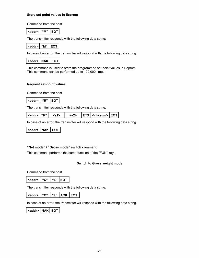
This command is used to store the programmed set-point values in Eeprom. This command can be performed up to 100,000 times.
Store set-point values in Eeprom
In case of an error, the transmitter will respond with the following data string.
<addr> NAK EOT
<addr> EOT “M”
Command from the host
The transmitter responds with the following data string:
<addr> “M” EOT
Request set-point values
In case of an error, the transmitter will respond with the following data string.
<addr> NAK EOT
<addr> EOT “R”
Command from the host
The transmitter responds with the following data string:
<addr> <s2> ETX <chksum> EOT <s1> “R”
“Net mode” / ”Gross mode” switch command
This command performs the same function of the “FUN” key.
Switch to Gross weight mode
Command from the host
<addr> “L” “C” EOT
The transmitter responds with the following data string:
<addr> “L” “C” ACK EOT
In case of an error, the transmitter will respond with the following data string.
<addr> NAK EOT
24
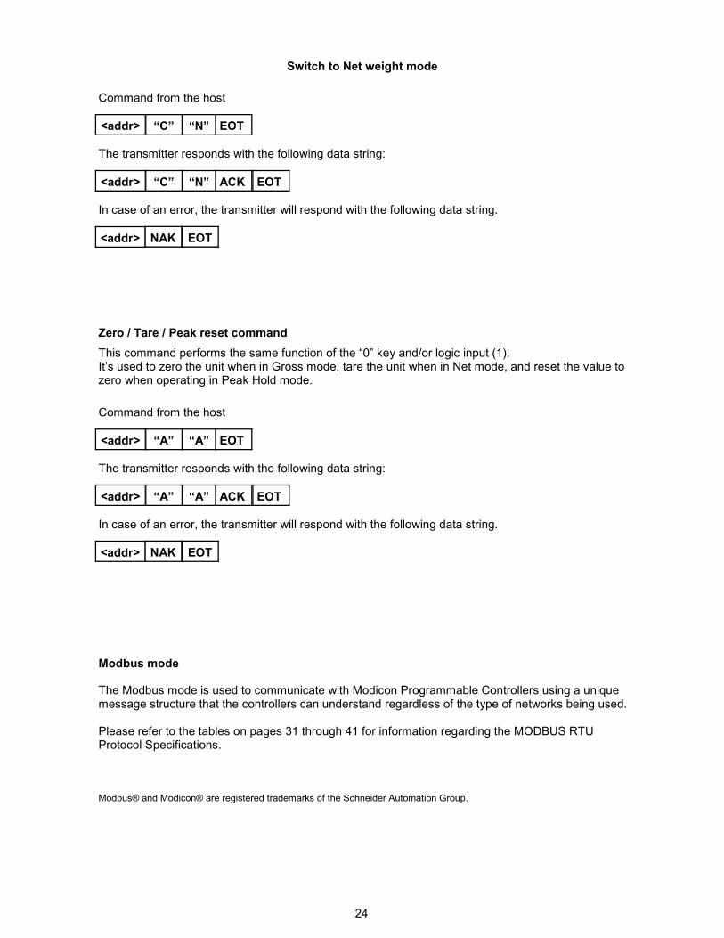
Modbus mode The Modbus mode is used to communicate with Modicon Programmable Controllers using a unique message structure that the controllers can understand regardless of the type of networks being used. Please refer to the tables on pages 31 through 41 for information regarding the MODBUS RTU Protocol Specifications. Modbus® and Modicon® are registered trademarks of the Schneider Automation Group.
Switch to Net weight mode
Command from the host
<addr> “N” “C” EOT
The transmitter responds with the following data string:
<addr> “N” “C” ACK EOT
In case of an error, the transmitter will respond with the following data string.
<addr> NAK EOT
Zero / Tare / Peak reset command
This command performs the same function of the “0” key and/or logic input (1). It’s used to zero the unit when in Gross mode, tare the unit when in Net mode, and reset the value to zero when operating in Peak Hold mode.
Command from the host
<addr> “A” “A” EOT
The transmitter responds with the following data string:
<addr> “A” “A” ACK EOT
In case of an error, the transmitter will respond with the following data string.
<addr> NAK EOT
25
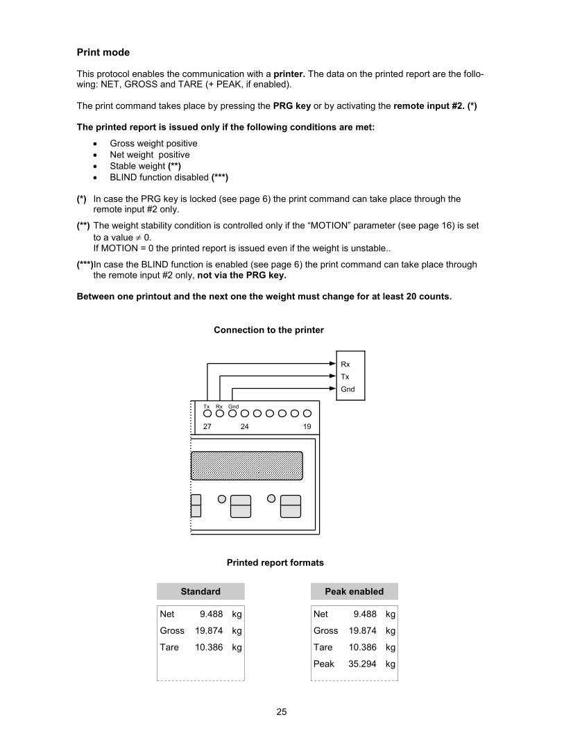
Print mode
This protocol enables the communication with a printer. The data on the printed report are the follo-wing: NET, GROSS and TARE (+ PEAK, if enabled).
The print command takes place by pressing the PRG key or by activating the remote input #2. (*) The printed report is issued only if the following conditions are met:
• Gross weight positive
• Net weight positive
• Stable weight (**)
• BLIND function disabled (***)
(*) In case the PRG key is locked (see page 6) the print command can take place through the remote input #2 only.
(**) The weight stability condition is controlled only if the “MOTION” parameter (see page 16) is set
to a value ≠ 0. If MOTION = 0 the printed report is issued even if the weight is unstable..
(***)In case the BLIND function is enabled (see page 6) the print command can take place through the remote input #2 only, not via the PRG key.
Between one printout and the next one the weight must change for at least 20 counts.
Gnd Tx Rx
19 27 24
Tx
Gnd
Rx
Connection to the printer
Printed report formats
Standard
Net
Gross
Tare
9.488
19.874
10.386
kg
kg
kg
Peak enabled
Net
Gross
Tare
9.488
19.874
10.386
kg
kg
kg
Peak 35.294 kg
26
24 23 22 21 20 19 24 23 22 21 20 19
Gnd Tx Rx
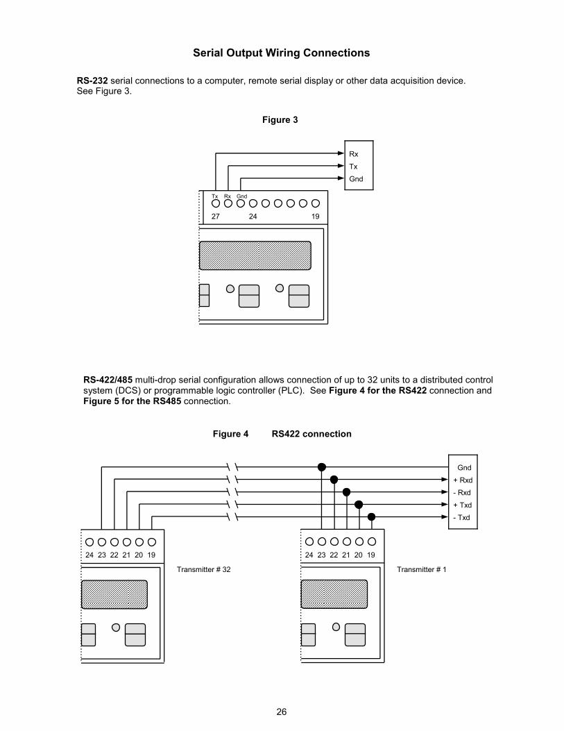
Serial Output Wiring Connections
RS-422/485 multi-drop serial configuration allows connection of up to 32 units to a distributed control system (DCS) or programmable logic controller (PLC). See Figure 4 for the RS422 connection and Figure 5 for the RS485 connection.
RS-232 serial connections to a computer, remote serial display or other data acquisition device. See Figure 3.
Figure 3
Transmitter # 1 Transmitter # 32
- Rxd
+ Txd
+ Rxd
- Txd
Gnd
Figure 4 RS422 connection
19 27 24
Tx
Gnd
Rx
27
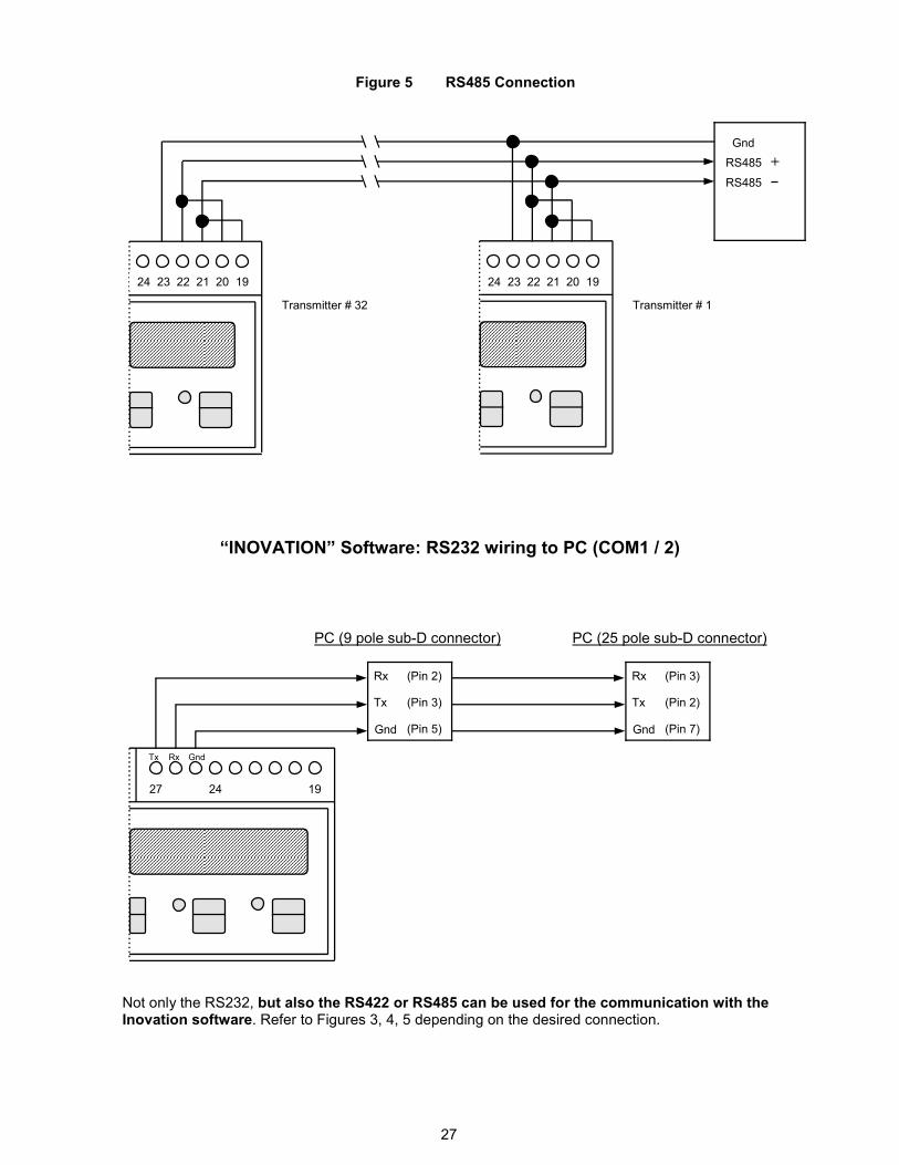
Gnd Tx Rx
“INOVATION” Software: RS232 wiring to PC (COM1 / 2)
19 27 24
Tx
Gnd
Rx (Pin 2)
(Pin 3)
(Pin 5)
PC (9 pole sub-D connector) PC (25 pole sub-D connector)
Tx
Gnd
Rx (Pin 3)
(Pin 2)
(Pin 7)
24 23 22 21 20 19
Transmitter # 1 Transmitter # 32
RS485
RS485
Gnd
Figure 5 RS485 Connection
+
24 23 22 21 20 19
Not only the RS232, but also the RS422 or RS485 can be used for the communication with the Inovation software. Refer to Figures 3, 4, 5 depending on the desired connection.
28
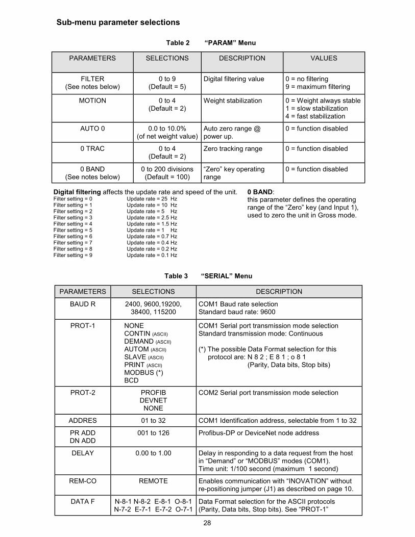
Sub-menu parameter selections
PARAMETERS SELECTIONS DESCRIPTION
FILTER (See notes below)
0 to 9 (Default = 5)
Digital filtering value
MOTION 0 to 4 (Default = 2)
Weight stabilization
AUTO 0 0.0 to 10.0% (of net weight value)
Auto zero range @ power up.
0 TRAC 0 to 4 (Default = 2)
Zero tracking range
VALUES
0 = no filtering 9 = maximum filtering
0 = Weight always stable 1 = slow stabilization 4 = fast stabilization
0 = function disabled
0 = function disabled
0 BAND (See notes below)
0 to 200 divisions (Default = 100)
“Zero” key operating range
0 = function disabled
Table 2 “PARAM” Menu
PARAMETERS SELECTIONS DESCRIPTION
BAUD R 2400, 9600,19200, 38400, 115200
COM1 Baud rate selection Standard baud rate: 9600
PROT-1 NONE CONTIN (ASCII) DEMAND (ASCII) AUTOM (ASCII) SLAVE (ASCII) PRINT (ASCII) MODBUS (*) BCD
COM1 Serial port transmission mode selection Standard transmission mode: Continuous (*) The possible Data Format selection for this protocol are: N 8 2 ; E 8 1 ; o 8 1 (Parity, Data bits, Stop bits)
PROT-2 PROFIB DEVNET NONE
COM2 Serial port transmission mode selection
ADDRES 01 to 32 COM1 Identification address, selectable from 1 to 32
PR ADD DN ADD
001 to 126 Profibus-DP or DeviceNet node address
DELAY 0.00 to 1.00 Delay in responding to a data request from the host in “Demand” or “MODBUS” modes (COM1). Time unit: 1/100 second (maximum 1 second)
REM-CO REMOTE Enables communication with “INOVATION” without re-positioning jumper (J1) as described on page 10.
DATA F N-8-1 N-8-2 E-8-1 O-8-1 N-7-2 E-7-1 E-7-2 O-7-1
Data Format selection for the ASCII protocols (Parity, Data bits, Stop bits). See “PROT-1”
Table 3 “SERIAL” Menu
Digital filtering affects the update rate and speed of the unit. Filter setting = 0 Update rate = 25 Hz Filter setting = 1 Update rate = 10 Hz Filter setting = 2 Update rate = 5 Hz Filter setting = 3 Update rate = 2.5 Hz Filter setting = 4 Update rate = 1.5 Hz Filter setting = 5 Update rate = 1 Hz Filter setting = 6 Update rate = 0.7 Hz Filter setting = 7 Update rate = 0.4 Hz Filter setting = 8 Update rate = 0.2 Hz Filter setting = 9 Update rate = 0.1 Hz
0 BAND: this parameter defines the operating range of the “Zero” key (and Input 1), used to zero the unit in Gross mode.
29
Sub-menu parameter selections (cont’d)
BAUD RATE
2400 9600 19,200 38,400
0 6 Hz 25 Hz 50 Hz 50 Hz
1 6 Hz 25 Hz 50 Hz 50 Hz
2 6 Hz 25 Hz 50 Hz 50 Hz
3 6 Hz 25 Hz 25 Hz 25 Hz
4 6 Hz 25 Hz 25 Hz 25 Hz
5 6 Hz 12 Hz 12 Hz 12 Hz
6 6 Hz 12 Hz 12 Hz 12 Hz
7 6 Hz 12 Hz 12 Hz 12 Hz
8 6 Hz 6 Hz 6 Hz 6 Hz
9 6 Hz 6 Hz 6 Hz 6 Hz
D I G I T A L F I L T E R
115,200
50 Hz
50 Hz
50 Hz
25 Hz
25 Hz
12 Hz
12 Hz
12 Hz
6 Hz
6 Hz
Table 4
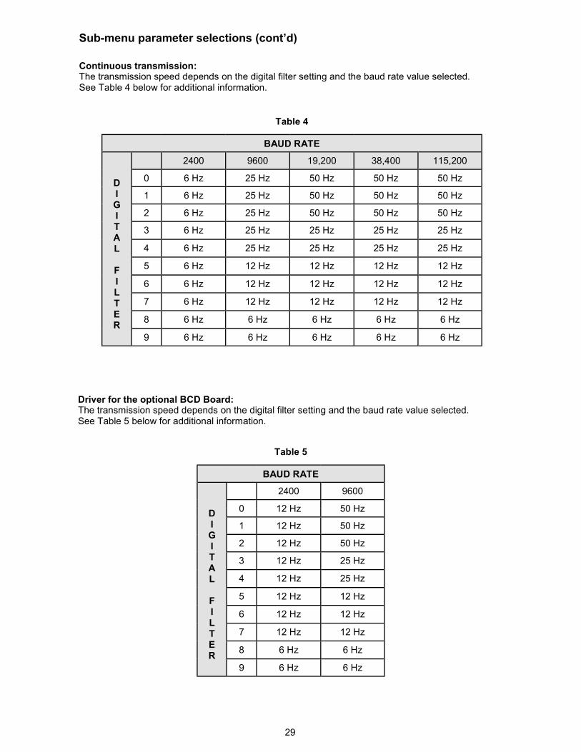
Continuous transmission: The transmission speed depends on the digital filter setting and the baud rate value selected. See Table 4 below for additional information.
BAUD RATE
D I G I T A L F I L T E R
2400 9600
0 12 Hz 50 Hz
1 12 Hz 50 Hz
2 12 Hz 50 Hz
3 12 Hz 25 Hz
4 12 Hz 25 Hz
5 12 Hz 12 Hz
6 12 Hz 12 Hz
7 12 Hz 12 Hz
8 6 Hz 6 Hz
9 6 Hz 6 Hz
Table 5
Driver for the optional BCD Board: The transmission speed depends on the digital filter setting and the baud rate value selected. See Table 5 below for additional information.
30
“IN - OUT” MENU
PARAMETERS SELECTIONS DESCRIPTION
MODE 1 GROSS NET
PEAK H
Operating mode selection for output number 1.
N.O N.C
Contact status below the setpoint value
POS. NEG.
Comparison with positive or negative weight values
Output enabled only after the weight reading has stabilized.
HYST - 1 (See notes below)
(Default = 2)
Hysteresis setting, used to eliminate chattering of the relay @ coincidence point.
TIMER 1 0.0 to 10.0 (0 = disabled)
The output is disabled after the time period has expired. (1/10 second increments )
DELAY 1 0.0 to 10.0 (0 = disabled)
Time delay before the output is enabled. (1/10 second increments)
Same parameter selections as above for output 2
TEST IN See page 18 Test procedure for inputs
TEST OUT Test procedure for outputs
NORMAL STABLE
Table 6
Sub-menu parameter selections (cont’d)
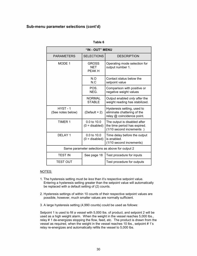
NOTES: 1. The hysteresis setting must be less than it’s respective setpoint value. Entering a hysteresis setting greater than the setpoint value will automatically be replaced with a default setting of (2) counts. 2. Hysteresis settings of within 10 counts of their respective setpoint values are possible, however, much smaller values are normally sufficient. 3. A large hysteresis setting (4,990 counts) could be used as follows: Setpoint 1 is used to fill a vessel with 5,000 lbs. of product, and setpoint 2 will be used as a high weight alarm. When the weight in the vessel reaches 5,000 lbs., relay # 1 de-energizes stopping the flow, feed, etc. The product is drawn from the vessel as required, when the weight in the vessel reaches 10 lbs., setpoint # 1’s relay re-energizes and automatically refills the vessel to 5,000 lbs.
31
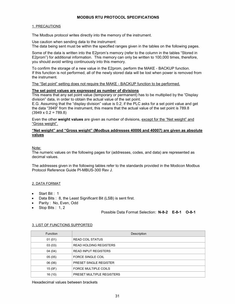
Function Description
01 (01) READ COIL STATUS
03 (03) READ HOLDING REGISTERS
04 (04) READ INPUT REGISTERS
05 (05) FORCE SINGLE COIL
06 (06) PRESET SINGLE REGISTER
15 (0F) FORCE MULTIPLE COILS
16 (10) PRESET MULTIPLE REGISTERS
MODBUS RTU PROTOCOL SPECIFICATIONS
3. LIST OF FUNCTIONS SUPPORTED
The Modbus protocol writes directly into the memory of the instrument.
Use caution when sending data to the instrument: The data being sent must be within the specified ranges given in the tables on the following pages.
Some of the data is written into the E2prom’s memory (refer to the column in the tables “Stored in E2prom”) for additional information. This memory can only be written to 100,000 times, therefore, you should avoid writing continuously into this memory.
To confirm the storage of a new value in the E2prom, perform the MAKE - BACKUP function. If this function is not performed, all of the newly stored data will be lost when power is removed from the instrument.
The “Set point” setting does not require the MAKE - BACKUP function to be performed.
The set point values are expressed as number of divisions This means that any set point value (temporary or permanent) has to be multiplied by the “Display division” data, in order to obtain the actual value of the set point. E.G. Assuming that the “display division” value is 0.2; if the PLC asks for a set point value and get the data “3949” from the instrument, this means that the actual value of the set point is 789.8 (3949 x 0.2 = 789.8)
Even the other weight values are given as number of divisions, except for the “Net weight” and “Gross weight”.
“Net weight” and “Gross weight” (Modbus addresses 40006 and 40007) are given as absolute values Note: The numeric values on the following pages for (addresses, codes, and data) are represented as decimal values. The addresses given in the following tables refer to the standards provided in the Modicon Modbus Protocol Reference Guide PI-MBUS-300 Rev J.
1. PRECAUTIONS
2. DATA FORMAT
• Start Bit : 1
• Data Bits : 8, the Least Significant Bit (LSB) is sent first.
• Parity : No, Even, Odd
• Stop Bits : 1, 2
Possible Data Format Selection: N-8-2 E-8-1 O-8-1
Hexadecimal values between brackets
32
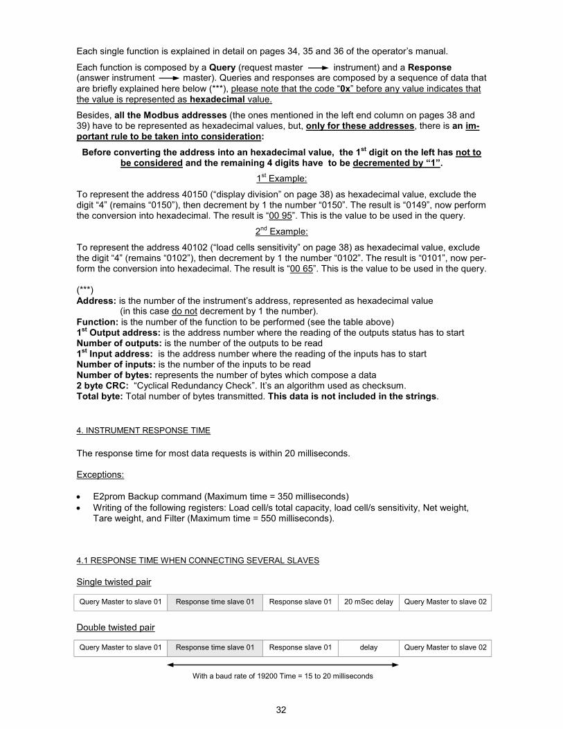
The response time for most data requests is within 20 milliseconds. Exceptions:
• E2prom Backup command (Maximum time = 350 milliseconds)
• Writing of the following registers: Load cell/s total capacity, load cell/s sensitivity, Net weight, Tare weight, and Filter (Maximum time = 550 milliseconds).
4. INSTRUMENT RESPONSE TIME
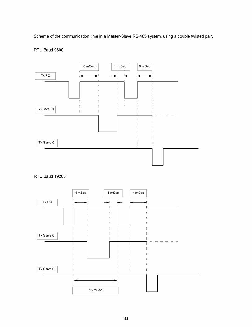
4.1 RESPONSE TIME WHEN CONNECTING SEVERAL SLAVES
Single twisted pair
Query Master to slave 01 Response time slave 01 Response slave 01 20 mSec delay Query Master to slave 02
Double twisted pair
Query Master to slave 01 Response time slave 01 Response slave 01 delay Query Master to slave 02
With a baud rate of 19200 Time = 15 to 20 milliseconds
Each single function is explained in detail on pages 34, 35 and 36 of the operator’s manual.
Each function is composed by a Query (request master instrument) and a Response (answer instrument master). Queries and responses are composed by a sequence of data that
are briefly explained here below (***), please note that the code “0x” before any value indicates that the value is represented as hexadecimal value.
Besides, all the Modbus addresses (the ones mentioned in the left end column on pages 38 and 39) have to be represented as hexadecimal values, but, only for these addresses, there is an im-portant rule to be taken into consideration:
Before converting the address into an hexadecimal value, the 1st digit on the left has not to
be considered and the remaining 4 digits have to be decremented by “1”.
1st Example:
To represent the address 40150 (“display division” on page 38) as hexadecimal value, exclude the digit “4” (remains “0150”), then decrement by 1 the number “0150”. The result is “0149”, now perform the conversion into hexadecimal. The result is “00 95”. This is the value to be used in the query.
2nd Example:
To represent the address 40102 (“load cells sensitivity” on page 38) as hexadecimal value, exclude the digit “4” (remains “0102”), then decrement by 1 the number “0102”. The result is “0101”, now per-form the conversion into hexadecimal. The result is “00 65”. This is the value to be used in the query. (***)
Address: is the number of the instrument’s address, represented as hexadecimal value (in this case do not decrement by 1 the number).
Function: is the number of the function to be performed (see the table above) 1st Output address: is the address number where the reading of the outputs status has to start
Number of outputs: is the number of the outputs to be read 1st Input address: is the address number where the reading of the inputs has to start
Number of inputs: is the number of the inputs to be read Number of bytes: represents the number of bytes which compose a data 2 byte CRC: “Cyclical Redundancy Check”. It’s an algorithm used as checksum. Total byte: Total number of bytes transmitted. This data is not included in the strings.
33
RTU Baud 9600
Scheme of the communication time in a Master-Slave RS-485 system, using a double twisted pair.
8 mSec 1 mSec 8 mSec
Tx PC
Tx Slave 01
Tx Slave 01
RTU Baud 19200
Tx PC
Tx Slave 01
Tx Slave 01
4 mSec 1 mSec 4 mSec
15 mSec
34
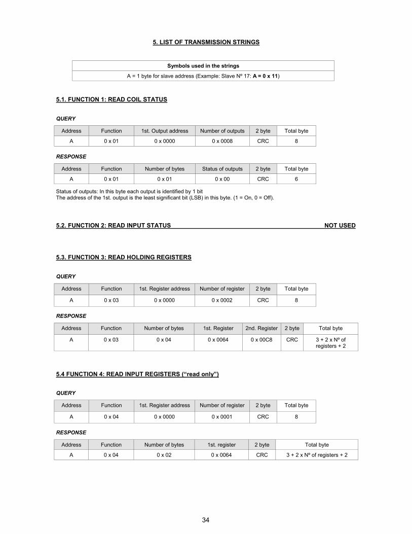
5. LIST OF TRANSMISSION STRINGS
Symbols used in the strings
A = 1 byte for slave address (Example: Slave Nº 17: A = 0 x 11)
QUERY
RESPONSE
Address Function Number of bytes Status of outputs 2 byte Total byte
A 0 x 01 0 x 01 0 x 00 CRC 6
Status of outputs: In this byte each output is identified by 1 bit The address of the 1st. output is the least significant bit (LSB) in this byte. (1 = On, 0 = Off).
5.1. FUNCTION 1: READ COIL STATUS
5.2. FUNCTION 2: READ INPUT STATUS NOT USED
5.3. FUNCTION 3: READ HOLDING REGISTERS
QUERY
Address Function 1st. Register address Number of register 2 byte Total byte
A 0 x 03 0 x 0000 0 x 0002 CRC 8
RESPONSE
Address Function Number of bytes 1st. Register 2nd. Register 2 byte Total byte
A 0 x 03 0 x 04 0 x 0064 0 x 00C8 CRC 3 + 2 x Nº of registers + 2
Address Function 1st. Output address Number of outputs 2 byte Total byte
A 0 x 01 0 x 0000 0 x 0008 CRC 8
5.4 FUNCTION 4: READ INPUT REGISTERS (“read only”)
QUERY
RESPONSE
Address Function Number of bytes 1st. register 2 byte Total byte
A 0 x 04 0 x 02 0 x 0064 CRC 3 + 2 x Nº of registers + 2
Address Function 1st. Register address Number of register 2 byte Total byte
A 0 x 04 0 x 0000 0 x 0001 CRC 8
35
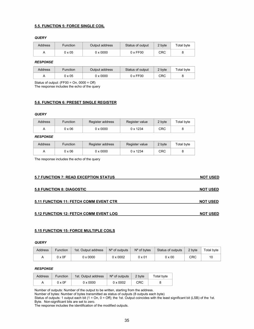
5.5. FUNCTION 5: FORCE SINGLE COIL
QUERY
Address Function Output address Status of output 2 byte Total byte
A 0 x 05 0 x 0000 0 x FF00 CRC 8
RESPONSE
Address Function Output address Status of output 2 byte Total byte
A 0 x 05 0 x 0000 0 x FF00 CRC 8
Status of output: (FF00 = On, 0000 = Off) The response includes the echo of the query
5.6. FUNCTION 6: PRESET SINGLE REGISTER
QUERY
Address Function Register address Register value 2 byte Total byte
A 0 x 06 0 x 0000 0 x 1234 CRC 8
RESPONSE
Address Function Register address Register value 2 byte Total byte
A 0 x 06 0 x 0000 0 x 1234 CRC 8
The response includes the echo of the query
5.7 FUNCTION 7: READ EXCEPTION STATUS NOT USED
5.8 FUNCTION 8: DIAGOSTIC NOT USED
5.11 FUNCTION 11: FETCH COMM EVENT CTR NOT USED
5.12 FUNCTION 12: FETCH COMM EVENT LOG NOT USED
5.15 FUNCTION 15: FORCE MULTIPLE COILS
QUERY
Address Function 1st. Output address Nº of outputs Nº of bytes Status of outputs 2 byte Total byte
A 0 x 0F 0 x 0000 0 x 0002 0 x 01 0 x 00 CRC 10
RESPONSE
Address Function 1st. Output address Nº of outputs 2 byte Total byte
A 0 x 0F 0 x 0000 0 x 0002 CRC 8
Number of outputs: Number of the output to be written, starting from the address. Number of bytes: Number of bytes transmitted as status of outputs (8 outputs each byte) Status of outputs: 1 output each bit (1 = On, 0 = Off); the 1st. Output coincides with the least significant bit (LSB) of the 1st. Byte. Non-significant bits are set to zero. The response includes the identification of the modified outputs.
36
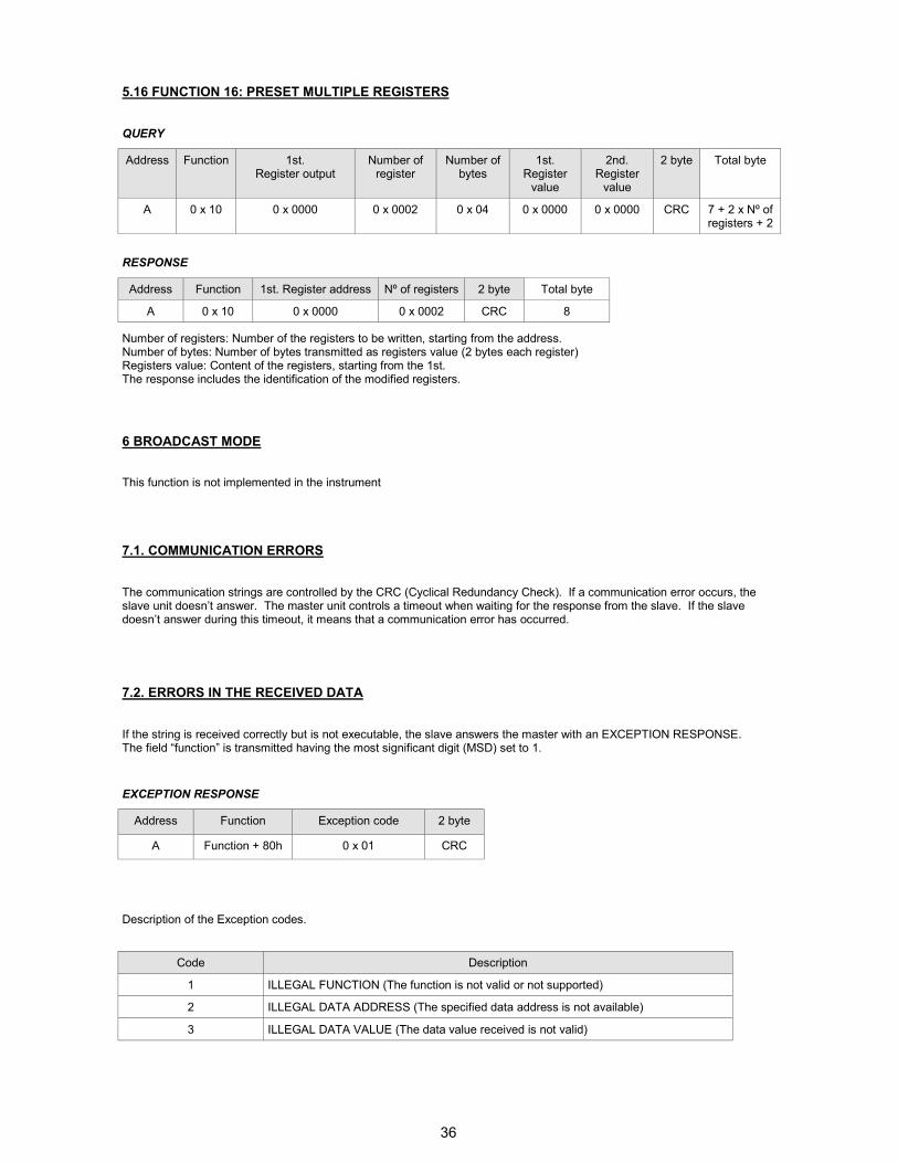
5.16 FUNCTION 16: PRESET MULTIPLE REGISTERS
QUERY
Address Function 1st. Register output
Number of register
Number of bytes
1st. Register value
2nd. Register value
2 byte Total byte
A 0 x 10 0 x 0000 0 x 0002 0 x 04 0 x 0000 0 x 0000 CRC 7 + 2 x Nº of registers + 2
RESPONSE
Address Function 1st. Register address Nº of registers 2 byte Total byte
A 0 x 10 0 x 0000 0 x 0002 CRC 8
Number of registers: Number of the registers to be written, starting from the address. Number of bytes: Number of bytes transmitted as registers value (2 bytes each register) Registers value: Content of the registers, starting from the 1st. The response includes the identification of the modified registers.
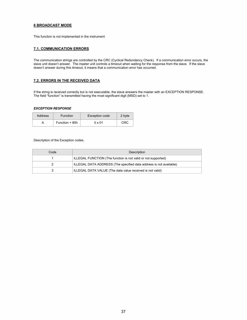
6 BROADCAST MODE
The communication strings are controlled by the CRC (Cyclical Redundancy Check). If a communication error occurs, the slave unit doesn’t answer. The master unit controls a timeout when waiting for the response from the slave. If the slave doesn’t answer during this timeout, it means that a communication error has occurred.
7.1. COMMUNICATION ERRORS
This function is not implemented in the instrument
7.2. ERRORS IN THE RECEIVED DATA
If the string is received correctly but is not executable, the slave answers the master with an EXCEPTION RESPONSE. The field “function” is transmitted having the most significant digit (MSD) set to 1.
EXCEPTION RESPONSE
Address Function Exception code 2 byte
A Function + 80h 0 x 01 CRC
Description of the Exception codes.
Code Description
1 ILLEGAL FUNCTION (The function is not valid or not supported)
2 ILLEGAL DATA ADDRESS (The specified data address is not available)
3 ILLEGAL DATA VALUE (The data value received is not valid)
37
6 BROADCAST MODE
The communication strings are controlled by the CRC (Cyclical Redundancy Check). If a communication error occurs, the slave unit doesn’t answer. The master unit controls a timeout when waiting for the response from the slave. If the slave doesn’t answer during this timeout, it means that a communication error has occurred.
7.1. COMMUNICATION ERRORS
This function is not implemented in the instrument
7.2. ERRORS IN THE RECEIVED DATA
If the string is received correctly but is not executable, the slave answers the master with an EXCEPTION RESPONSE. The field “function” is transmitted having the most significant digit (MSD) set to 1.
EXCEPTION RESPONSE
Address Function Exception code 2 byte
A Function + 80h 0 x 01 CRC
Description of the Exception codes.
Code Description
1 ILLEGAL FUNCTION (The function is not valid or not supported)
2 ILLEGAL DATA ADDRESS (The specified data address is not available)
3 ILLEGAL DATA VALUE (The data value received is not valid)
38
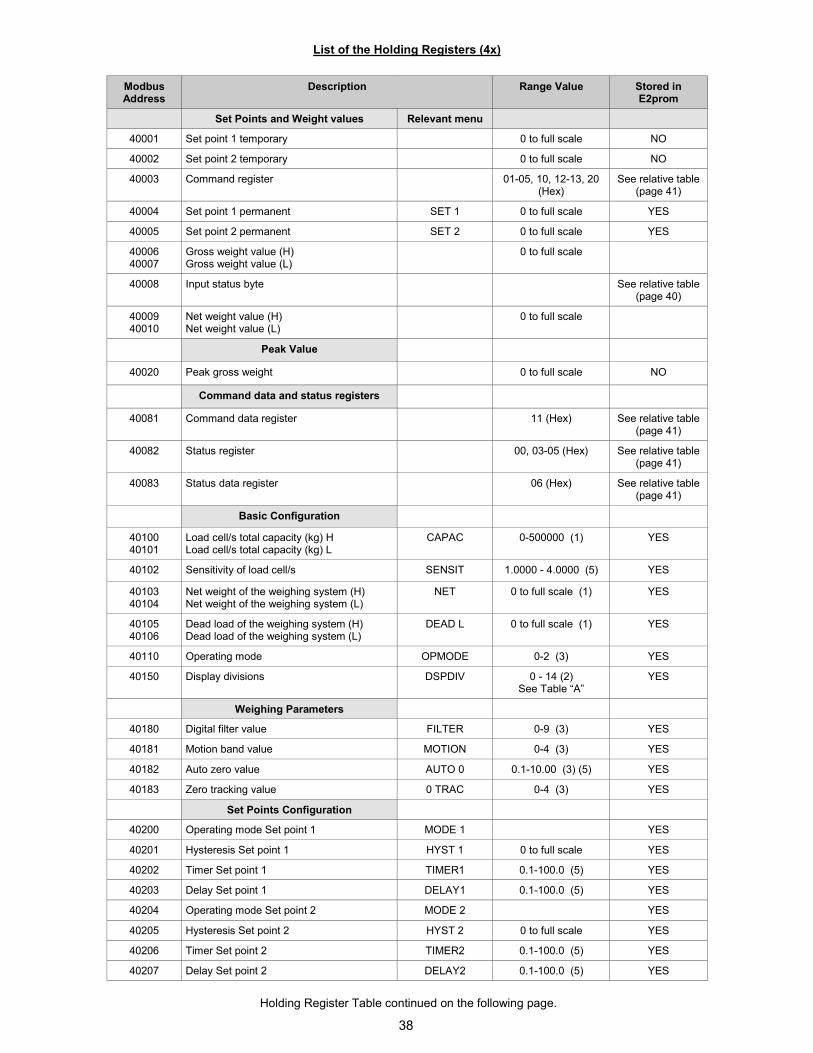
Modbus Address
Description Range Value Stored in E2prom
Set Points and Weight values Relevant menu
40001 Set point 1 temporary 0 to full scale NO
40002 Set point 2 temporary 0 to full scale NO
40003 Command register 01-05, 10, 12-13, 20 (Hex)
See relative table (page 41)
40004 Set point 1 permanent SET 1 0 to full scale YES
40005 Set point 2 permanent SET 2 0 to full scale YES
40006 40007
Gross weight value (H) Gross weight value (L)
0 to full scale
40008 Input status byte See relative table (page 40)
40009 40010
Net weight value (H) Net weight value (L)
0 to full scale
Peak Value
40020 Peak gross weight 0 to full scale NO
Command data and status registers
40081 Command data register 11 (Hex) See relative table (page 41)
40082 Status register 00, 03-05 (Hex) See relative table (page 41)
40083 Status data register 06 (Hex) See relative table (page 41)
Basic Configuration
40100 40101
Load cell/s total capacity (kg) H Load cell/s total capacity (kg) L
CAPAC 0-500000 (1) YES
40102 Sensitivity of load cell/s SENSIT 1.0000 - 4.0000 (5) YES
40103 40104
Net weight of the weighing system (H) Net weight of the weighing system (L)
NET 0 to full scale (1) YES
40105 40106
Dead load of the weighing system (H) Dead load of the weighing system (L)
DEAD L 0 to full scale (1) YES
40110 Operating mode OPMODE 0-2 (3) YES
40150 Display divisions DSPDIV 0 - 14 (2) See Table “A”
YES
Weighing Parameters
40180 Digital filter value FILTER 0-9 (3) YES
40181 Motion band value MOTION 0-4 (3) YES
40182 Auto zero value AUTO 0 0.1-10.00 (3) (5) YES
40183 Zero tracking value 0 TRAC 0-4 (3) YES
Set Points Configuration
40200 Operating mode Set point 1 MODE 1 YES
40201 Hysteresis Set point 1 HYST 1 0 to full scale YES
40202 Timer Set point 1 TIMER1 0.1-100.0 (5) YES
40203 Delay Set point 1 DELAY1 0.1-100.0 (5) YES
40204 Operating mode Set point 2 MODE 2 YES
40205 Hysteresis Set point 2 HYST 2 0 to full scale YES
40206 Timer Set point 2 TIMER2 0.1-100.0 (5) YES
40207 Delay Set point 2 DELAY2 0.1-100.0 (5) YES
List of the Holding Registers (4x)
Holding Register Table continued on the following page.
39
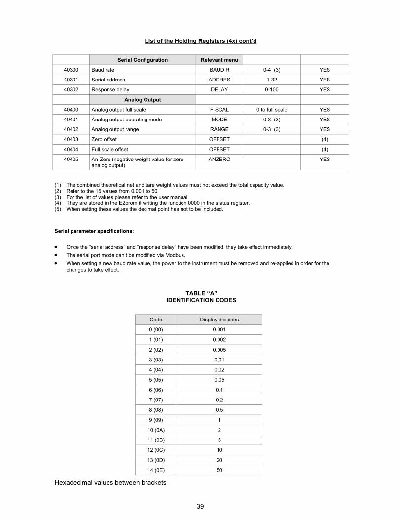
List of the Holding Registers (4x) cont’d
(1) The combined theoretical net and tare weight values must not exceed the total capacity value. (2) Refer to the 15 values from 0.001 to 50 (3) For the list of values please refer to the user manual. (4) They are stored in the E2prom if writing the function 0000 in the status register. (5) When setting these values the decimal point has not to be included.
Serial parameter specifications:
• Once the “serial address” and “response delay” have been modified, they take effect immediately.
• The serial port mode can’t be modified via Modbus.
• When setting a new baud rate value, the power to the instrument must be removed and re-applied in order for the
changes to take effect.
TABLE “A” IDENTIFICATION CODES
Code Display divisions
0 (00) 0.001
1 (01) 0.002
2 (02) 0.005
3 (03) 0.01
4 (04) 0.02
5 (05) 0.05
6 (06) 0.1
7 (07) 0.2
8 (08) 0.5
9 (09) 1
10 (0A) 2
11 (0B) 5
12 (0C) 10
13 (0D) 20
14 (0E) 50
Serial Configuration Relevant menu
40300 Baud rate BAUD R 0-4 (3) YES
40301 Serial address ADDRES 1-32 YES
40302 Response delay DELAY 0-100 YES
Analog Output
40400 Analog output full scale F-SCAL 0 to full scale YES
40401 Analog output operating mode MODE 0-3 (3) YES
40402 Analog output range RANGE 0-3 (3) YES
40403 Zero offset OFFSET (4)
40404 Full scale offset OFFSET (4)
40405 An-Zero (negative weight value for zero analog output)
ANZERO YES
Hexadecimal values between brackets
40
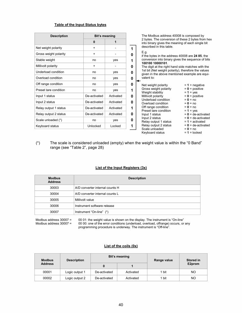
Table of the Input Status bytes
Description Bit’s meaning
0 1
Net weight polarity + -
Gross weight polarity + -
Stable weight no yes
Millivolt polarity + -
Underload condition no yes
Overload condition no yes
Off range condition no yes
Preset tare condition no yes
Input 1 status De-activated Activated
Input 2 status De-activated Activated
Relay output 1 status De-activated Activated
Relay output 2 status De-activated Activated
Scale unloaded (*) no yes
Keyboard status Unlocked Locked
List of the Input Registers (3x)
Modbus Address
Description
30003 A/D converter internal counts H
30004 A/D converter internal counts L
30005 Millivolt value
30006 Instrument software release
30007 Instrument “On-line” (*)
List of the coils (0x)
Modbus Address
Description
Bit’s meaning Range value
0 1
00001 Logic output 1 De-activated Activated 1 bit NO
00002 Logic output 2 De-activated Activated 1 bit NO
Stored in E2prom
The Modbus address 40008 is composed by 2 bytes. The conversion of these 2 bytes from hex into binary gives the meaning of each single bit described in this table.
E.g.
if the bytes in the address 40008 are 24 85, the conversion into binary gives the sequence of bits
100100 10000101. The digit at the right hand side matches with the 1st bit (Net weight polarity), therefore the values given in the above mentioned example are equi-valent to:
Net weight polarity = 1 = negative Gross weight polarity = 0 = positive Weight stability = 1 = yes Millivolt polarity = 0 = positive Underload condition = 0 = no Overload condition = 0 = no Off range condition = 0 = no Preset tare condition = 1 = yes Input 1 status = 0 = de-activated Input 2 status = 0 = de-activated Relay output 1 status = 1 = activated Relay output 2 status = 0 = de-activated Scale unloaded = 0 = no Keyboard status = 1 = locked
1
0
1
0
0
0
0
1
0
0
1
0
0
1
(*) The scale is considered unloaded (empty) when the weight value is within the “0 Band” range (see “Table 2”, page 28)
Modbus address 30007 = 00 01: the weight value is shown on the display. The instrument is “On-line” Modbus address 30007 = 00 00: one of the error conditions (underload, overload, offrange) occurs, or any programming procedure is underway. The instrument is “Off-line”.
41
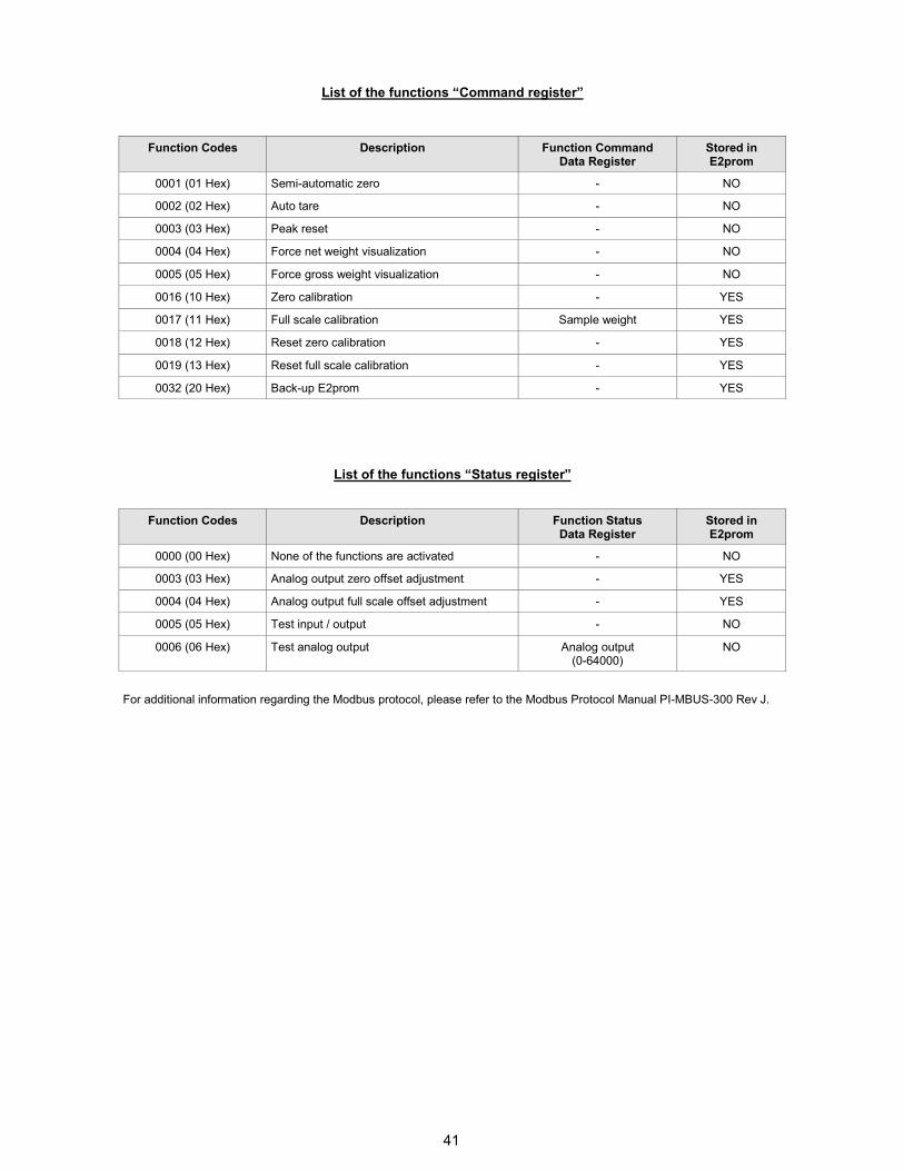
List of the functions “Command register”
Function Codes Description Function Command Data Register
Stored in E2prom
0001 (01 Hex) Semi-automatic zero - NO
0002 (02 Hex) Auto tare - NO
0003 (03 Hex) Peak reset - NO
0004 (04 Hex) Force net weight visualization - NO
0005 (05 Hex) Force gross weight visualization - NO
0016 (10 Hex) Zero calibration - YES
0017 (11 Hex) Full scale calibration Sample weight YES
0018 (12 Hex) Reset zero calibration - YES
0019 (13 Hex) Reset full scale calibration - YES
0032 (20 Hex) Back-up E2prom - YES
List of the functions “Status register”
Function Codes Description Function Status Data Register
Stored in E2prom
0000 (00 Hex) None of the functions are activated - NO
0003 (03 Hex) Analog output zero offset adjustment - YES
0004 (04 Hex) Analog output full scale offset adjustment - YES
0005 (05 Hex) Test input / output - NO
0006 (06 Hex) Test analog output Analog output (0-64000)
NO
For additional information regarding the Modbus protocol, please refer to the Modbus Protocol Manual PI-MBUS-300 Rev J.
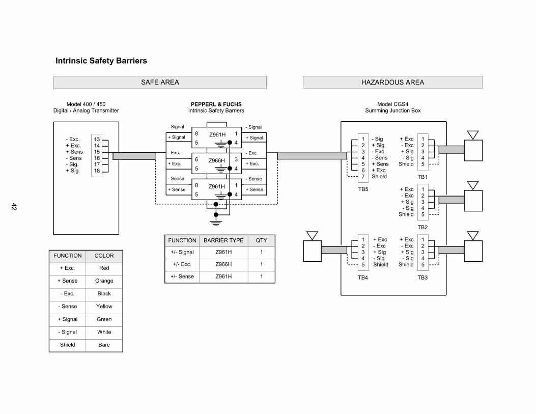
42
Intrinsic Safety Barriers
FUNCTION COLOR
+ Exc. Red
+ Sense Orange
- Exc. Black
- Sense Yellow
+ Signal Green
- Signal White
Shield Bare
FUNCTION BARRIER TYPE QTY
Z961H 1
Z966H 1
Z961H 1
+/- Signal
+/- Exc.
+/- Sense
HAZARDOUS AREA
1 2 3 4 5
1 2 3 4 5 6 7
TB4
TB5
1 2 3 4 5
1 2 3 4 5
1 2 3 4 5
TB1
TB2
TB3
- Sig + Sig - Exc - Sens + Sens + Exc Shield
+ Exc - Exc + Sig - Sig Shield
+ Exc - Exc + Sig - Sig
Shield
+ Exc - Exc + Sig - Sig
Shield
+ Exc - Exc + Sig - Sig
Shield
SAFE AREA
8
5
Z961H
4
1
6
5
Z966H
4
3
8
5
Z961H
4
1
- Signal
+ Signal
- Exc.
+ Exc.
- Sense
+ Sense
- Signal
+ Signal
- Exc.
+ Exc.
- Sense
+ Sense
13 14 15 16 17 18
- Exc. + Exc. + Sens - Sens - Sig. + Sig.
Model 400 / 450 Digital / Analog Transmitter
Model CGS4 Summing Junction Box
PEPPERL & FUCHS Intrinsic Safety Barriers
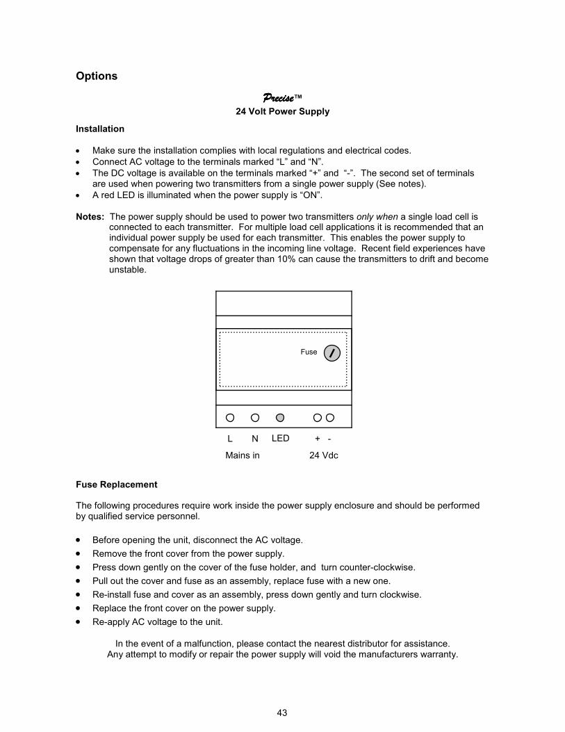
43
PrecisePrecisePrecisePrecise™ 24 Volt Power Supply
Installation
• Make sure the installation complies with local regulations and electrical codes.
• Connect AC voltage to the terminals marked “L” and “N”.
• The DC voltage is available on the terminals marked “+” and “-”. The second set of terminals are used when powering two transmitters from a single power supply (See notes).
• A red LED is illuminated when the power supply is “ON”.
Notes: The power supply should be used to power two transmitters only when a single load cell is connected to each transmitter. For multiple load cell applications it is recommended that an individual power supply be used for each transmitter. This enables the power supply to compensate for any fluctuations in the incoming line voltage. Recent field experiences have shown that voltage drops of greater than 10% can cause the transmitters to drift and become unstable.
Fuse Replacement The following procedures require work inside the power supply enclosure and should be performed by qualified service personnel.
• Before opening the unit, disconnect the AC voltage.
• Remove the front cover from the power supply.
• Press down gently on the cover of the fuse holder, and turn counter-clockwise.
• Pull out the cover and fuse as an assembly, replace fuse with a new one.
• Re-install fuse and cover as an assembly, press down gently and turn clockwise.
• Replace the front cover on the power supply.
• Re-apply AC voltage to the unit.
In the event of a malfunction, please contact the nearest distributor for assistance.
Any attempt to modify or repair the power supply will void the manufacturers warranty.
L N + -
Mains in 24 Vdc
Fuse
LED
Options

44
EC DECLARATION OF CONFORMITY
We: Pavone Sistemi S.r.l.
Via dei Chiosi, 18 20040 CAVENAGO BRIANZA (MI)
Hereby declares that the product: DAT 400 Complies with the essential requirements of the directives 73/23/CEE, 89/336/CEE, 93/68/CEE, when used for its intended purpose The product is made in accordance with the following standards
ELECTROMAGNETIC COMPATIBILITY:
EN 61000-3-2 EN 61000-3-3 EN 61000-6-2 EN 61000-6-3 EN 61326-1
ELECTRICAL SAFETY:
EN 61010-1
The CE mark has been applied on the product Cavenago Brianza, April 15, 2004
The Manager