precast flooring federationprecast flooring federation (pff), which receive careful consideration...
TRANSCRIPT

Code of Practice:For the Safe Erection of Precast Concrete Flooring and Associated Components
Precast Flooring Federation
Cover.indd 1 9/6/08 15:53:57
�
The Precast Flooring Federation have received the following endorsement with regards to this edition of the Code of Practice on 24th October 2007
“HSE encourages and welcomes industry codes of practice such as this produced by the Precast Flooring Federation (PFF), which receive careful consideration and input from key players within the industry who have the safety and welfare of those involved in precast flooring work foremost in their mind.
Falls have always been, and remain the biggest cause of deaths and serious injuries in construction. If work at height is planned, including selecting the correct equipment and using it properly, then most accidents involving falls can be prevented. As with previous editions of this code and other similar industry codes of practice, if the guidance within it is properly followed by the industry, then the risks of death and injury from falls and other factors should be greatly reduced.
My thanks go to the PFF and those involved in revising this code of practice. It brings together best practice within the industry and has the interest of those involved in the design, specification, use and erection of precast flooring products at heart. It is only by the industry showing leadership, working in partnership, and taking ownership of the management of risk that improvements will be made, and I commend its use to all concerned.”
Stephen WilliamsChief Inspector of ConstructionHealth and Safety Executive
HSE

��
The Precast Flooring Federation’s (PFF) Code of Practice for the Safe Erection of Precast Concrete Flooring and Associated Components has now run for several editions and since the previous edition in 2001 there have been many developments, not only in Health and Safety legislation, but also in best practice within the industry.
The Code attempts to give a guide to the current best practice, but in an ever-changing situation, can only be totally up-to-date at the time of its publication.
The PFF is committed to achieving a high standard and universal approach to Health and Safety within its membership, and part of this is the provision to employees, customers and designers alike of clearly presented information about the systems of work employed and attendances required.
This edition of the Code of Practice has been some two years in preparation and the patience of the membership and of the Health and Safety Executive, who have provided invaluable assistance with its development, is much appreciated.
It is intended that this edition will be published almost exclusively as a download from the PFF website although a number of printed copies will be made available to members, training organisations and the Health and Safety Executive.
Installation of precast flooring components is acknowledged to be a potentially high risk activity, as it involves the use of heavy plant, cranes and personnel working at height. This Code of Practice is, therefore, used as the basis for the training of Erectors, Foremen and Supervisors to ensure that all have the skills and competence to carry out their roles in a safe manner. This training is predominantly carried out via the training programme developed jointly between the PFF and Proskills.
The PFF gratefully acknowledges the help and guidance provided by the Health and Safety Executive in the preparation of this Code and is pleased to be able to include the endorsement of Stephen Williams of HSE. The PFF has also received support and comment from the Major Contractors Group.
Foreword
Published and distributed by the Precast Flooring Federation60 Charles Street, Leicester, LE1 1FB Tel: +44 116 253 6161 Fax: +44 116 251 4568 www.precastfloors.infoThis edition published 2007A catalogue record for this book is available from the British LibraryISBN: 0 9536773 5 4Previous edition published 2001, ISBN 0 9536773 1 1
Every effort has been made to ensure that the statements made and advice given provide a safe and accurate guide;however, no liability or responsibility of any kind (including liability for negligence) can be accepted in this respect by thepublishers or the authors.
���
DraftingCommittee:ParticipantsatTimeofDrafting
CodeofPractice
The assistance of former committee members, including David Burgess,Derek Llewellyn and Chris Beasley is acknowledged.
M.ThurmanCMIOSH,MIISRM
N.Brown
P.Thomas
M.Allanson
B.Jermy
A.Shuter
B.Findlater
N.Clark
N.Hutton
P.Abbott
M.Bradley
B.Bruce
A.Mayne
J.Neville
SMotlibGradIOSH,MIISRM
Chairman
Secretary
ColtmanPrecastConcreteLtd
PrecastFlooringFederation
HealthandSafetyExecutive
Beresford’sFlooringLtd
CarterConcreteLtd
CarterConcreteLtd
CEMEXConcreteFloors
HansonBuildingProducts
HansonBuildingProducts
LongleyConcreteFlooring
MeltonConcreteProducts
MilbankFloorsLtd
MilbankFloorsLtd
TarmacTopfloorLtd
TarmacTopfloorLtd
�v
Contents
Section0.10.2
SECTION1:1.1
1.21.31.41.51.61.71.8
SECTION2:2.12.22.32.42.5
SECTION3:3.13.23.33.43.5
SECTION4:4.14.24.34.44.54.64.74.84.9
SECTION5:5.15.25.35.4
SECTION6:6.16.26.36.46.5
SECTION7:7.17.27.37.4
TitleDEFINITIONSREFERENCES
MANAGEMENTOFHEALTHANDSAFETYManagementofHealthandSafetyatWorkRegulationsandApprovedCodeofPracticeManualHandlingOperationsPersonalProtectiveEquipmentatWorkProvisionandUseofWorkEquipmentWelfareFacilitiesControlofSubstancesHazardoustoHealth(COSHH)NoiseatWorkOccupationalHealth
SAFEWORKINGMETHODSTATEMENTSANDPRE-STARTCHECKSContentofSafeWorkingMethodStatementsCommunicationoftheSafeWorkingMethodStatementAdditionstotheSafeWorkingMethodStatementSpecialConsiderationsPre-StartChecks
TRAININGANDCERTIFICATIONScopeResponsibilityGeneralProcedureTrainingCertification/Competency
DESIGNSTAGECONSIDERATIONSTheExistingEnvironmentDesignandPlanningConstructionPhaseLifting,PlacingandSafeHandlingofUnitsInstallationofPrecastConcreteFloorsonMasonryImposedLoadsDuringtheConstructionPhaseStabilityofSupportingStructureDuringtheInstallationHealthandSafetyFilePoorBuildingPractices
CONTRACTOR’SRESPONSIBILITIESAttendancesManagementofConstructionWorksPreventionofDamagetoPrecastUnitsHandrailingtoPrecastStairUnits
COMPANYREPRESENTATIVE’SROLEAgreedSequenceofInstallationMethodofLiftingSiteAccessAttendancesLiaisonSupervisionofInstallation
FOREMAN’SROLEWorkingtoSequencePre-startCheckSupervisionofInstallationWorkmanship
Pagevi
viii
12
69
1011111212
141517171818
192020202121
22232324252629293030
3132323232
333434353535
3637373738

v
Contents
SECTION8:8.18.28.38.48.5
SECTION9:9.19.2
SECTION10:10.110.210.310.410.510.610.710.810.910.1010.1110.1210.1310.14
SECTION11:11.111.211.3
SECTION12:12.112.212.312.4
SECTION13:13.113.213.313.413.513.613.713.813.9
SECTION14:14.114.2
SECTION15:15.1
AppendixAAppendixB
TRANSPORTATIONOFCOMPONENTSANDACCESSTOSITETheStackingandMakingSecureofLoadsLoadingSequenceSiteAccessOffloadingInspectionofPrecastConcreteFlooringandotherComponentsPriortoInstallation
ONSITESTORAGEOFCOMPONENTSStackingatGroundLevelTemporaryStorageonInstalledFlooring
SAFEUSEOFCRANES,FORKLIFTSANDOTHERLIFTINGEQUIPMENTManagementoftheLiftingOperationControloftheLiftingOperationDocumentation-Certificates,RecordsandRegistersStartofLiftingOperationTowerCranesUseofOnSiteEquipmentWeatherRestrictionsLowHeadroomSituationsLiftingPrestressedPrecastFlooringUnitsatanAngleChainSlingsMultipleLegSlingsPatentLiftingDevicesLiftingForksandBlockHandlingDevicesLiftingGrabs
MOVEMENTOFUNITSBYOTHERMEANSBarringJackingOtherMeansofInstallingorMovingComponents
ADDITIONALONSITEWORKSTemporaryStructuralSupportPropingInsituConcreteFormingofHoles
ACCESSTOWORKINGAREA,WORKATHEIGHT,PROTECTIONAGAINSTFALLSIntroductionGeneralPrinciplesforControlMeasuresSafeAccesstotheWorkingAreaWorkingatHeight–ControlMeasuresT-BeamandBlockStaircasesFallsfromDeliveryVehiclesUseofLaddersRescueProcedures
PROTECTIONOFTHIRDPARTIESOtherTradesorPersonsonSiteMembersofthePublic
SUPPLIERANDSUB-CONTRACTORCOMPETENCYASSESSMENTAssessmentCriteria
Health,SafetyandWelfareAttendancesConstruction(DesignandManagement)Regulations2007
394040404142
434445
464749505258585959606061616262
63646565
66676767
68
69707071717777828384
868788
8990
9193
v�
Mostofthetermsusedinthisdocumentareincommonuse. However, the following definitions are intended toremoveanyambiguity.
0.1 Definitions
APPOINTEDPERSON:
The person employed by the COMPANY to have overall control of the lifting operation and to act on behalf of the COMPANY. The Appointed Person must have adequate training and experience to ensure the implementation of a safe system of work.
ASINSTALLEDDRAWING:
The layout drawings confirming actually‘as installed’ positions of precast flooring/ component positions, issued for the client’s safety file.
ATTENDANCES:
The standard PFF Health, Safety and Welfare Attendances, a copy of which is included asan Appendix to this Code.
BUILDINGDESIGNER:
The designer of the building or structure receiving the precast flooring components.
CDMCO-ORDINATOR:
The individual or organisation appointedby the client as CDM Co-ordinator under the Construction (Design and Management) Regulations.
CERTIFICATED:
Having been trained and qualified to fulfila particular role. Generally, holding a valid licence/certificate of training gained by attending a recognised course of instruction for the task in question.
COMPANY:
The precast flooring sub-contractor engaged in the supply and/or erection of flooring or precast components.
COMPANYREPRESENTATIVE:
A Supervisor/Contracts Manager (usually travelling) in the Installation Company’s employ with a responsibility for a number of contracts. A competent person trained to assess all health, safety and welfare arrangements in relation to company operations.
COMPONENTS:
Any member, article, or item, which comprises precast concrete or ancillary metalwork.
CONTRACTOR:
The CONTRACTOR shall mean the precast concrete sub-contractor’s client, who is responsible for co-ordinating all Principal Contractor requirements and attendances for the contract. Where the CONTRACTOR has overall responsibility for the construction phase of the project the CONTRACTOR shall also mean the PRINCIPAL CONTRACTOR.
CONTRACTOR’SSITEREPRESENTATIVE:
The person in charge of the day to day running of a particular site or project, i.e. Site Manager, Site Agent, General Foreman, Project Manager, Contracts Manager.
CRANEOPERATOR:
A competent and trained person responsible for the correct operation of the crane in accordance with the Manufacturer’s Operating Instructions, the Safe Working Method Statement and directions from the nominated SLINGER/SIGNALLER.
CRANESUPERVISOR:
The person designated by the APPOINTED PERSON to supervise the lifting operations, where the APPOINTED PERSON has deemed the operations as basic or standard, as defined by BS 7121-3:2000 Section 4.8.

v��
0.1 Definitions
Mostofthetermsusedinthisdocumentareincommonuse. However, the following definitions are intended toremoveanyambiguity.
DESIGNER:The person or persons who actually produces specifications, estimates, drawings, details, designs or calculations for a particular contract.
EMPLOYINGORGANISATION:The person or organisation requiring a lifting operation to be carried out and who has responsibility for safe use of the crane.
ERECTOR:A person who, after suitable training, is competent to carry out all functions of a SLINGER/SIGNALLER, also can hoist, place and secure precast concrete sections. This includes all plumbing/levelling and lining up, this person has the ability and training to work safely, and has a general understanding of structural stability issues. An ERECTOR may be employed by the Company, a specialist erection company or be self-employed.
FLOORING:The precast concrete componentsthat form the structural element of a floor and may include associated precast components.
FOREMAN:The person in charge of the precast erection team, actually undertaking the site work for the COMPANY.
GROUTING:Filling of voids between adjacent units to stabilise the floor and/or form a structural connection between units.
HOLLOWCORE:Precast concrete flooring system, which for the purposes of this document is deemed to include terms such as ‘wideslab’, ‘solid planks’ etc.
INSTALLER:The COMPANY, ERECTOR or an individual working for or on behalf of the COMPANY.
OPERATIVES:All other site personnel involved with the precast works, not including ERECTORS.
PRECASTDESIGNER:The designer of the precast flooring units, working for or on behalf of the COMPANY.
PRINCIPALCONTRACTOR:The contractor with overall responsibility for the construction phase of the project.
SIGNALLER(BANKSMAN):The person with responsibilities, after suitable certificated training, for directing the safe movement of a load attached to a crane and for the movement of the crane on site.
SLINGER:A person who has been suitably trained in the proper selection of lifting tackle, the slinging of loads to the crane attachment, while taking into account the capabilities of the crane employed.
WORKAREA:The area on a site or building where precast flooring/components are being erected.This includes the area covered by the radius of a crane from lifting off a lorry (or stack)to the final position.
WORKATHEIGHT:Work where there is a significant risk of injury due to falling.
WORKINGDRAWINGS:The layout drawings, section and details, produced by the PRECAST DESIGNER and issued for client approval, production and erection purposes.

v���
• Health and Safety at Work etc. Act. 1974
• The Management of Health and Safety at Work Regulations 1999
• The Work at Height Regulations 2005
• The Health and Safety (First Aid) Regulations 1981
• The Control of Noise at Work Regulations 2005*
• The Electricity at Work Regulations 1989
• The Personal Protective Equipment at Work Regulations 1992
• The Provision and Use of Work Equipment Regulations 1998-PUWER
• The Lifting Operations and Lifting Equipment Regulations 1998-LOLER
• The Manual Handling Operations Regulations 1992
• The Control of Substances Hazardous to Health Regulations 2002
• The Construction (Design and Management) Regulations 2007
• The Reporting of Injuries, Diseases and Dangerous Occurrences Regulations 1995
• The Control of Vibration at Work Regulations 2005
• The New Roads and Streetworks Act 1991
The following Health and SafetyExecutive Guidance Notes are alsorelevant:
• GS 6 Avoidance of Danger from Overhead Electrical Lines 1997
• HSG 141 Electrical Safety On Construction Sites
• HSG 144 The Safe Use of Vehicles On Construction Sites
• HSG 149 Backs For The Future – Safe Manual Handling In Construction
• HSG 150 Health and Safety in Construction
• CIS No 10 Tower Scaffolds (rev 4)
• HSE Information Sheet MISC 614 Preventing Falls from Boom Type Mobile Elevating Work Platforms
The following Construction IndustryAdvisory Committee Documents arealsorelevant:
A Guide to Managing Health and Safety in Construction, British Standards and other guidance notes are issued on a continuing basis and users of this Code of Practice should acquaint themselves with the latest updates and revisions.
• BS 5975: 1996 Code of Practice for Falsework
• BS 7121 Code of Practice for Safe Use of Cranes Parts 1, 2, 3 and 5
• BS 5628 Code of Practice for Use of Masonry
• BS 8110 Structural Use of Concrete Part 1: Code of Practice for design and construction
• BS EN 1992-1-1 Design of Concrete Structures
• PAS 59: 2004 Filled Collective Fall Arrest Systems
• CIRIA Special Publication
• SP 130: Site Safety Handbook
0.2 References

Section 1:Management of Health and Safety
The Health and Safety at Work Act 1974 places several general duties on employers, employees and others. Regulations are made under Section 16 of the Act. The Regulations referred to in the introductory notes are a legal requirement and must be adhered to at all times. For more information, refer to the documents themselves, listed in the References, and where necessary obtain competent, professional advice and approval on safety matters.
Precast Flooring Federation
Sect
ion
1
Dividers.indd 1 9/6/08 15:52:44

�
The Management of Health and Safety at Work Regulations requires all employers and self-employed operatives to assess the risk to the health and safety of workers and any others who may be affected by the work carried out.
Assessments will help to identify all the protective and preventative measures that need to be taken to comply with legislation to ensure that health and safety standards are maintained. Guidance on the procedures for risk assessment can be found in the Approved Code of Practice, under Management of Health and Safety at Work Regulations, which includes advice on the selection of preventative and protective measures.
Before an assessment of risk can be made it is important to understand the terms used, the two most important being:
Hazard - is something with the potential to cause harm Risk- expresses the likelihood that the harm from a particular hazard is realised
Most employers will be capable of undertaking the risk assessment themselves using expertise within their own organisations. Where there are complex hazards or equipment, it may be necessary to employ the help of external health and safety professionals.
The key actions to be taken can be summarised as below:
• These regulations require an employer to make a suitable assessment of the risks to the health and safety of employees and others who may be exposed to those risks. This includes contractors or temporary staff engaged for specific work.
• Where the risk is considered to be significant, the assessment must be recorded in writing and should identify those personnel especially at risk.
• Risk assessments must be regularly reviewed and altered if they are no longer valid or circumstances/ conditions have changed significantly.
• A nominated competent person (or persons if required) must be appointed to assist in complying with the regulations.
• Emergency procedures must be established, and competent people nominated to implement them.
• Information must be provided to the employees on the risks identified, the control measures to be taken, the names of the competent persons and information on the risks identified where employers share work areas.
• Training must be given to employees in respect of the duties placed upon them by the regulations, at induction when first employed, when transferred, or if the job changes. This training must be updated and repeated periodically to take account of any changes.
In addition employees have certain duties under the regulations:
• To make full and proper use of anything provided by the employer in accordance with the training given. This includes safety equipment, machinery, substances, means of transport, etc.
• Employees must also inform the employer (or nominated persons) of any dangerous work situation or any matter relating to the employer’s health and safety arrangements.
1.1 ManagementofHealthandSafetyatWork RegulationsandApprovedCodeofPractice

�
GeneralProcedureofRiskAssessment
1. Identify the hazards and activities.
2. Where possible the hazards identified should be removed/minimised by design.
3. Assess the risks i.e. the nature and extent of the risks.
4. Assess existing control measures or precautions for adequacy and decide if any further measures needed.
5. Check for compliance with other legal requirements.
6. Record the findings and arrangements and inform as required.
1.1 ManagementofHealthandSafetyatWork RegulationsandApprovedCodeofPractice
1.1.1
�
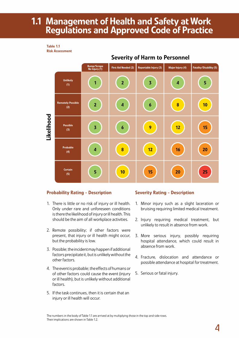
ProbabilityRating-Description
1. There is little or no risk of injury or ill health. Only under rare and unforeseen conditions is there the likelihood of injury or ill health. This should be the aim of all workplace activities.
2. Remote possibility; if other factors were present, that injury or ill health might occur, but the probability is low.
3. Possible; the incident may happen if additional factors precipitate it, but is unlikely without the other factors.
4. The event is probable; the effects of humans or of other factors could cause the event (injury or ill health), but is unlikely without additional factors.
5. If the task continues, then it is certain that an injury or ill health will occur.
SeverityRating-Description
1. Minor injury such as a slight laceration or bruising requiring limited medical treatment.
2. Injury requiring medical treatment, but unlikely to result in absence from work.
3. More serious injury, possibly requiring hospital attendance, which could result in absence from work.
4. Fracture, dislocation and attendance or possible attendance at hospital for treatment.
5. Serious or fatal injury.
1.1 ManagementofHealthandSafetyatWork RegulationsandApprovedCodeofPractice
Table1.1RiskAssessment
The numbers in the body of Table 1.1 are arrived at by multiplying those in the top and side rows.Their implications are shown in Table 1.2.
High
Low
SeverityofHarmtoPersonnel
Medium
High
MediumLow
Low Medium High
Medium Medium High
High High VeryHigh
Fatality/Disability(5)MajorInjury(4)
Low Medium High
Medium Medium High
High High VeryHigh
Certain(5)
Medium Medium High
High High VeryHigh
20
25
15
10
5
16
20
12
8
4
12
15
9
6
3
8
10
6
4
2
4
5
3
2
1
Probable(4)
Possible(3)
RemotelyPossible(2)
Unlikely(1)
ReportableInjury(3)FirstAidNeeded(2)Bump/ScrapeNoInjury(1)
Like
lihoo
d

�
An alternative method using high, medium and low ratings is shown in Table 1.3.
1.1 ManagementofHealthandSafetyatWork RegulationsandApprovedCodeofPractice
Table1.2SummaryforDefinitionsandReviewFrequency
Table1.3AlternativeRiskAssessment
Likelihood Severity RiskDescriptionGuide
MinimumReviewFrequency
Low
High
Medium
Unlikely Noinjury,bruise,scrape
Low-iffurtheractionisidentifieditshould
betakenwhenreasonablypracticable
Afteranyincidentorwithin12-18months
Remotelypossible Firstaidrequired Asabove
PossibleLosttimeincident
(inc.restrictedworkcase)
Medium-allfurtheractionshouldbetaken
immediately
Probable Major Asbeloworwhenreasonablypracticable
Certain Fatality/disabilityHigh-noworktoproceeduntilall
furtheractionhasbeencompleted
Beforethecommencement
ofwork.
Afteranyincidentorwithin6-12months
Values(Riskrating)
High
Low
Likelihood
Medium
High
MediumLow
Low Medium High
Medium Medium High
High High VeryHigh
�
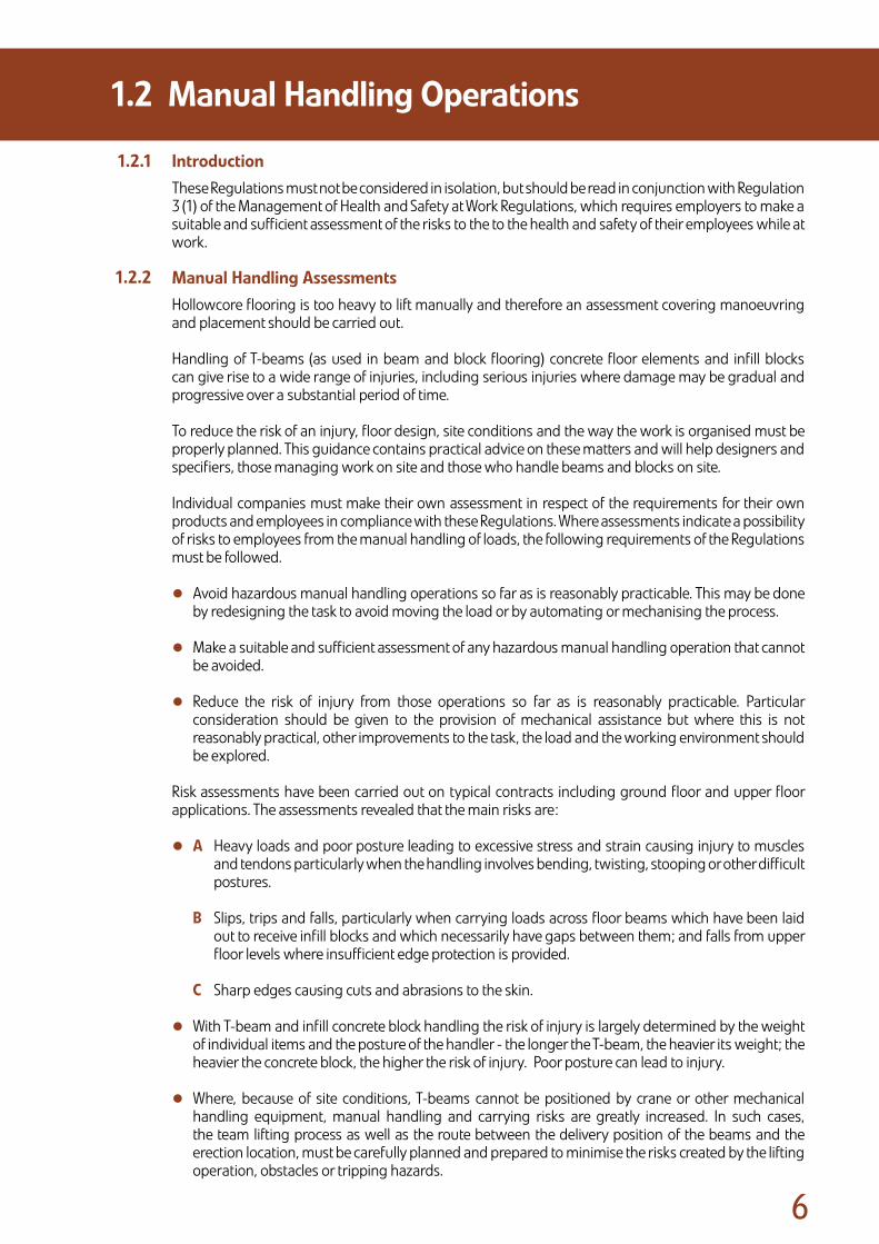
IntroductionThese Regulations must not be considered in isolation, but should be read in conjunction with Regulation 3 (1) of the Management of Health and Safety at Work Regulations, which requires employers to make a suitable and sufficient assessment of the risks to the to the health and safety of their employees while at work.
ManualHandlingAssessmentsHollowcore flooring is too heavy to lift manually and therefore an assessment covering manoeuvring and placement should be carried out.
Handling of T-beams (as used in beam and block flooring) concrete floor elements and infill blocks can give rise to a wide range of injuries, including serious injuries where damage may be gradual and progressive over a substantial period of time.
To reduce the risk of an injury, floor design, site conditions and the way the work is organised must be properly planned. This guidance contains practical advice on these matters and will help designers and specifiers, those managing work on site and those who handle beams and blocks on site.
Individual companies must make their own assessment in respect of the requirements for their own products and employees in compliance with these Regulations. Where assessments indicate a possibility of risks to employees from the manual handling of loads, the following requirements of the Regulations must be followed.
• Avoid hazardous manual handling operations so far as is reasonably practicable. This may be done by redesigning the task to avoid moving the load or by automating or mechanising the process.
• Make a suitable and sufficient assessment of any hazardous manual handling operation that cannot be avoided.
• Reduce the risk of injury from those operations so far as is reasonably practicable. Particular consideration should be given to the provision of mechanical assistance but where this is not reasonably practical, other improvements to the task, the load and the working environment should be explored.
Risk assessments have been carried out on typical contracts including ground floor and upper floor applications. The assessments revealed that the main risks are:
• A Heavy loads and poor posture leading to excessive stress and strain causing injury to muscles and tendons particularly when the handling involves bending, twisting, stooping or other difficult postures.
B Slips, trips and falls, particularly when carrying loads across floor beams which have been laid out to receive infill blocks and which necessarily have gaps between them; and falls from upper floor levels where insufficient edge protection is provided.
C Sharp edges causing cuts and abrasions to the skin.
• With T-beam and infill concrete block handling the risk of injury is largely determined by the weight of individual items and the posture of the handler - the longer the T-beam, the heavier its weight; the heavier the concrete block, the higher the risk of injury. Poor posture can lead to injury.
• Where, because of site conditions, T-beams cannot be positioned by crane or other mechanical handling equipment, manual handling and carrying risks are greatly increased. In such cases, the team lifting process as well as the route between the delivery position of the beams and the erection location, must be carefully planned and prepared to minimise the risks created by the lifting operation, obstacles or tripping hazards.
1.2 ManualHandlingOperations
1.2.1
1.2.2
�
• The final positioning of T-beams in ground floor situations usually permits the erector to stand below the level of the floor beam and, although the movement required is not excessive, if considerable stooping outside the floor area is required to grasp the load, the risk of injury is high.
• The final positioning of T-beams in upper floors typically requires the erector to stand on the same level as that on which the floor beam is resting. In this situation, if the erector is required to grasp the load at or below foot level and the risk of injury is high.
• When ‘blocking-out’, packs of blocks are placed onto pre-positioned T-beams. The blocks are then carried from the packs and laid into the floor beam recess below foot level.
Precautions
• Where possible designers and specifiers should minimise the length of floor beams to keep their weight as low as reasonably practicable. Typically, 150mm floor T-beams weigh 32kg/metre and 225mm floorT-beams weigh 60kg/metre.
• Infill blocks should be of the lightest type available within the specification required for the properties of the finished floor.
• Project Planners, Designers and Contractors should ensure that the items listed below are taken into account when planning the work and when devising safe systems of work. Contractors should also give instruction and exercise supervision to ensure that workers follow these plans and systems of work.
T-BeamandBlockSystems–SafeWorkingMethodConsiderationsThe following should be considered when writing the company procedures for the handling and erecting of T-beams and infill blocks:
• Plan to off load floor beams from the delivery lorry directly onto the walls on which they will be finally positioned using a crane or other suitable mechanical handling equipment.
• Wherever reasonably practicable provide craneage of sufficient capacity to cover the whole of the floor area being laid.
• Where positioning of T-beams and blocks cannot be achieved using a crane or other mechanical handling device, trolleys or bogies should be used to convey the items. The route must be prepared and be clear of obstacles or tripping hazards.
• Erectors should adjust their work rate to permit short breaks to be taken at regular intervals and should rotate their duties.
• Ensure sufficient time is allowed for the completion of the work allocation.
• Packs of infill blocks should be positioned as close as possible to the laying positions.
• Blocks should never be thrown from one person to another.
1.2 ManualHandlingOperations
1.2.3
1.2.4

�
TheWorkingEnvironmentThe roads and routes around the site should be prepared in advance of the delivery of the beams and blocks. If they are not to be off loaded into their laying position, suitable stacking areas should be prepared.
In areas where the beams and blocks are carried or handled, the site should be kept clear of obstacles and tripping hazards. Uneven, slippery or unstable ground conditions increase the risk of injury.
TrainingErectors must be given information and training on manual handling risks, their prevention and the systems of work to be used on that site to ensure safe manual handling of beams and blocks. Suitable training will also be necessary for designers, specifiers and those managing contracts.
IndividualCapabilityParticular consideration must be given to employees who are known to have a history of back trouble, hernia or other health problems that could affect their manual handling capability.
HealthSurveillanceEmployers should conduct appropriate health surveillance in order to identify at an early stage any indications that the employee is suffering injury due to the manual handling of T-beams and blocks, thereby enabling further harm to be prevented.
1.2 ManualHandlingOperations
1.2.6
1.2.8
1.2.5
1.2.7

�
IntroductionThe Personal Protective Equipment at Work Regulations 1992 (PPE Regs.) place requirements on the use of personal protective equipment (PPE) in the work place.
The Health and Safety Executive (HSE) has prepared specific guidance on the regulations after widespread consultation with industry. Readers should refer to the guidance on the regulations produced by the HSE.
The HSE document contains advice on the selection of PPE, considers the different types of PPE available, and identifies some of the processes and activities which may require PPE to be worn.
WorkingClothesandPersonalProtectiveEquipmentThe PPE Regs. require the Employer to provide suitable PPE necessary for the protection of Operatives and Erectors engaged in the erection of precast concrete flooring. The requirements for PPE must be identified on the General Risk Assessment.
All Operatives and Erectors, irrespective of the nature of particular site conditions, must be provided with, and must wear, PPE to meet general needs, in particular safety footwear, high visibility clothing, abrasion resistant gloves, weatherproof clothing and suitable head protection. All PPE must be properly stored and maintained in accordance with manufacturers’ recommendations.
The distribution and quality of such equipment are matters of individual company policy. However, all protective equipment or clothing must carry the CE Mark, identifying the product as having passed certain European Standards, or be of a standard at least equal to that set by the appropriate British Standard.
Wherever possible, the Company should consider the views and comments received from their Operatives and Erectors when deciding upon particular types of equipment. The physical stature of Operatives and Erectors should be matched as closely as is practicable by any equipment. PPE must also be compatible with other PPE worn, e.g. hearing protection worn with head protection.
The company must ensure that all protective clothing and equipment is fit for use and should apply all necessary measures to ensure that their employees are using such items in proper manner. Operatives and Erectors issued with such equipment have a duty under the Health and Safety at Work etc. Act 1974 to use and look after it. The company must ensure that Operatives and Erectors receive adequate instruction and training regarding the proper use, storage, maintenance and replacement of PPE and clothing.
On certain sites, the conditions or method of working will necessitate the use of special protective clothing and equipment. Certain items such as eye protection, respiratory protection, ear protection and safety harnesses should be carried by the erection team at all times and used as the need arises or should be made available to the erection team prior to the commencement of work. The use of specific protective equipment, e.g. safety harnesses, must be identified in the Method Statement.
The Erectors should conduct regular inspections of all equipment and clothing and any items found to be missing or defective should be notified to the Company for immediate replacement or repair.
1.3 PersonalProtectiveEquipment atWork
1.3.2
1.3.1
10
GeneralThe Provision and Use of Work Equipment Regulations 1992 (PUWER) lay down important Health and Safety requirements regarding work equipment. The primary objective of PUWER is to ensure the provision of safe work equipment and its safe use. The PUWER make more explicit the general duties on employers, the self-employed and persons in control to provide safe plant and equipment. The PUWER must not be considered in isolation; in particular, they need to be read in conjunction with the Management of Health and Safety at Work Regulations 1999.
Although the prime duty for ensuring health and safety rests with employers, employees also have legal duties, particularly under Section 7 and 8 of The Health and Safety at Work etc Act 1974. These duties have been supplemented by Regulation 14 of The Management of Health and Safety at Work Regulations 1999, which require that employees must correctly use all work items provided by their employer in accordance with the training and instructions they received to enable them to use the items safely.
VibrationandVibratingToolsHand arm vibration is vibration transmitted from work processes into workers’ hands and arms. It can typically be caused by operating hand-held power tools such as portable disc cutters.
Regular or frequent exposure to high levels of vibration can lead to permanent injury. This is most likely to occur when contact with a vibrating tool or process is a regular part of a person’s job. Occasional exposure is unlikely to cause injury, although it should be avoided by people with medical conditions such as Raynaud’s Disease.
Health and safety law requires the Company to assess the risk to the health of employees, plan for its control and manage the risk. This will include provision of suitable equipment, correct maintenance of equipment and providing employees with information and training on health risks and safe use of the equipment.
RecognitionandControlofRiskThe documentation supplied by the equipment manufacturer should warn of risks from vibration. Regular use of hand-held power tools may give rise to potential risk.
The risks identified following assessment can be controlled in many ways. Advice and approval should be sought from a competent safety professional and the equipment manufacturers.
It is therefore recommended that the Company should assess the level of vibration generated by hand-held power tools and minimise exposure to this equipment in line with guidance.
1.4 ProvisionandUseofWorkEquipment Regulations
1.4.2
1.4.1
1.4.3

11
The provision of welfare facilities on the majority of sites will be on a shared welfare basis, where the Contractor provides the necessary facilities which can be used by Operatives and Erectors engaged in the precast flooring erection.
When no formal welfare arrangements exist, the Company should ensure that the necessary facilities are provided by way of an attendance, based upon the PFF Standard Health, Safety and Welfare Attendances (Appendix A) issued at quotation stage, or alternatively, the Company may provide facilities for use by Operatives and Erectors.
The ultimate responsibility for ensuring that the facilities are provided, and that they are of a standard equal to that required by the CDM, remains with the Company, and therefore, the Company’s Representative must satisfy himself that the facilities provided, from whatever source, are adequate.
IntroductionIn order to comply with the Control of Substances Hazardous to Health Regulations (COSHH), the Company must ensure the collection and issue of up to date information on the potential hazards and toxicity of all materials and substances used by the Company in carrying out its site activities, and the control measures to be adopted.
Materials and substances include anything used or generated, e.g. ready mixed concrete, dust from cutting operations etc.
GeneralProcedureAssessment sheets for all products used on site are to be issued to the Company Representative.
All Operatives involved in the use of these materials, e.g. cement, ready-mixed concrete, etc. will be reminded of the hazards from the particular material about to be used, all necessary precautions and any PPE that will be made available. This equipment will be put into use before any substance is utilised on site.
All substances received on site will be stored in accordance with the instructions contained in the Assessment Sheets and in the event of any spillage, appropriate action must be taken to retrieve the material, in accordance with instructions contained in the Assessment Sheets. The Company Representative should monitor these procedures.
Empty containers and waste material must be disposed of in accordance with the approved procedures, as noted on the Assessment Sheet for the product or products concerned.
The materials used in the erection of precast concrete floors are generally of low toxicity but all Operatives must be reminded of the hazards at all times by the Company. Checks that control measures are being adhered to should be made at periodic intervals by the Company Representative.
Copies of COSHH Assessment sheets may form part of the Company’s Work Method Statement.
The Company Representative should request the Contractor to supply details of any other substances on site that could affect the Company’s employees or their sub-contractors.
1.5 WelfareFacilities
1.6.1
1.6.2
1.6 ControlofSubstancesHazardous toHealth(COSHH)

1�
The Control of Noise at Work Regulations 2005 place certain duties on employers, employees and manufacturers. The noise created by drilling, cutting, etc. may be excessive and could cause a health hazard that requires assessment and control.
Actionlevels First action level 80 dB (A) Second action level 85 dB (A)
Where employees are exposed between the first and second action levels the employer is required to provide protectors to employees who so request and ensure that the employees have been trained in their correct use.
Where employees are exposed above the second action level the wearing of ear protection is mandatory. The employer must provide hearing protection and ensure that the protectors are used and the employee has been trained in their correct use.
IntroductionHealth is an important area to manage. The health of those installing precast concrete can be affected if the work is not properly controlled. To assist in monitoring the effectiveness of the controls described in this Code of Practice, the following recommendations are made regarding pre-employment health screening and health surveillance.
Pre-employmentHealthScreeningPre-employment health screening is an essential requirement in establishing the fitness of a potential new employee for the tasks which he will perform. It is also necessary to record the health status of the new employee so that any changes can be measured during the course of their employment.
A person applying for a position as trainee, Erector or Foreman, should be provided with a brief questionnaire to assist the company in assessing any potential health problems that could affect their suitability to do the job that they are applying for. The questionnaire should include questions on the following, but is not limited to those listed below:
• Noise and noisy environments.
• Dust and dusty environments.
• Skin complaints such as dermatitis.
• Vibration and work with vibrating tools.
In addition, where a potential employee is to work in an area where they may come into contact with, or be exposed to substances or situations that could affect their health they will be provided with a pre-employment medical examination.
In any case it is recommended that all new employees are assessed for the following:
• Audiometry (assessment of hearing where an employee is likely to work with noisy equipment).
• Lung function.
• Hand arm vibration assessment (where the person has reported suffering from the problem and will use vibrating tools during the course of employment).
Where a person is going to be the SLINGER/SIGNALLER it is recommended that vision screening is carried out.
1.7 NoiseatWork
1.8.1
1.8.2
1.8 OccupationalHealth

1�
HealthSurveillance
It is recommended that employees undergo general health surveillance at a frequency to be determined by the employer’s risk assessment and policy. This will allow the company to identify where a persons health has been affected. The health surveillance should cover the following:
Audiometry
Where noise levels exceed 80 dB (A), those persons exposed should be screened for hearing loss.
Vibration
Where persons are exposed to vibration to their hand and arms, e.g. in the use of cut off saws, etc. then they should be screened for disease related to hand arm vibration syndrome. The initial screening can be carried out by using a self assessment questionnaire, followed up by specialist consultation where the questionnaire results indicate that this is necessary.
Skincondition
It is recommended that any person who is likely to be exposed to chemicals or substances that are known to be capable of causing occupational dermatitis are subject to regular skin inspections as part of the health screening arrangements and in addition are trained to recognise the symptoms related to occupational dermatitis.
Lungfunction
Where persons are likely to be exposed to dust it is recommended that lung function tests are carried out. Where a person is exposed to 0.1 mg/m3 (8-hour time weighted average) of respirable silica, a chest x-ray should be carried out every three years.
Vision
Where a person is operating or controlling mobile plant it is recommended that vision screening is carried out.
The records of the surveillance must be kept strictly confidential in accordance with all current legislation on Data Protection. Access to these records is limited and the person to whom the records relate must be asked for their permission in writing before any medical report can be requested from Doctors and other specialists. The results of the surveillance should be passed to one nominated individual within the company, so that they can arrange any changes to work patterns or arrange referral to an occupational health physician or specialist as required.
1.8.3
1.8 OccupationalHealth

Section 2:Safe Working Method Statements and Pre-Start Checks
Safe Working Method Statements form part of the overall Safety Management System, covering hazardous activities, such as the erection of precast flooring and associated components. They provide the information on the arrangements and, where required, the actual sequence of work necessary to manage health and safety. Basic information must be provided and communicated to all concerned parties at the planning stage, thus allowing time for approval or modification of the Safe Working Method Statements prior to site erection.
Precast flooring erection is similar in nature on many sites and therefore a Safe Working Method Statement will contain common elements and activities. However, the Safe Working Method Statements must take account of specific site conditions/requirements, information from the Health and Safety Plan/Design Risk Assessment, and/or contractor’s requirements.
Precast Flooring Federation
Sect
ion
2
Dividers.indd 2 9/6/08 15:52:44

1�
Safe Working Method Statements must be concise but informative and should contain the following information as a minimum:
2.1 ContentofSafeWorkingMethodStatements
Part1:ManagementandControl
The name of the Contractor �n charge of the s�te
The address at wh�ch the proposed work �s to be carr�ed out
The po�nt of contact at the s�te
Contractor
S�te address
S�te Manager / Agent / Contact
Br�ef descr�pt�on of the work to be carr�ed out - may �nclude the number of v�s�ts that w�ll be necessary to complete the contract
How the un�ts w�ll be l�fted and pos�t�oned and other relevant requ�rements. e.g. w�ll propp�ng be requ�red and where w�ll work commence?
The crane type (rat�ng and style, tonnage, mob�le, tower, etc). General locat�on of the crane, etc.
The max�mum ‘we�ght/rad�us’ for each component type must be stated and any recommendat�ons from the crane suppl�ers must be cons�dered
The form of transport by wh�ch the components are to be del�vered and the access requ�rements, e.g. hardstand�ng
Descr�pt�on ofcontract
Method of erect�on and sequence of work
Crane type/pos�t�on
Max�mum component we�ghts and crane work�ng rad�us
Del�ver�es ands�te access
The adequacy of bear�ngs and the person respons�ble for check�ng them pr�or to work commenc�ng. The person respons�b�le for ensur�ng stab�l�ty and the method used
Stab�l�ty and bear�ngs
Part2:DescriptionandInformation(contract,siteandplant)
Part3:StabilityandBearings
1�
2.1 ContentofSafeWorkingMethodStatements
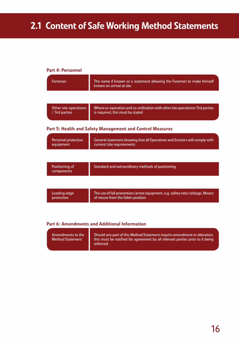
Part4:Personnel
The name �f known or a statement allow�ng the Foreman to make h�mself known on arr�val at s�te
Statement to confirm the competence and tra�n�ng of Sl�nger/S�gnaller and Erectors who w�ll be �nvolved �n the erect�on
Where co-operat�on and co-ord�nat�on w�th other s�te operat�ons/�rd part�es �s requ�red, th�s must be stated
Foreman
Sl�nger/S�gnaller(Banksman) Erectors
Other s�te operat�ons / �rd part�es
General statement show�ng that all Operat�ves and Erectors w�ll comply w�th current/s�te requ�rements
Method of access and the Contractor’s respons�b�l�ty to supply. The use of scaffold�ng, temporary access, etc.
Standard and extraord�nary methods of pos�t�on�ng
Statement regard�ng the prov�s�on of handra�ls and other means of protect�on
The use of fall prevent�on/arrest equ�pment, e.g. safety nets/a�rbags. Means of rescue from the fallen pos�t�on
Prov�s�on of fac�l�t�es, e.g. first a�d and to�lets
Personal protect�ve equ�pment
Access to work area
Pos�t�on�ng ofcomponents
Work�ng at he�ghts
Lead�ng edge protect�on
Welfare fac�l�t�es
Should any part of th�s Method Statement requ�re amendment or alterat�on, th�s must be not�fied for agreement by all relevant part�es pr�or to �t be�ng enforced
Amendments to the Method Statement
Part5:HealthandSafetyManagementandControlMeasures
Part6:AmendmentsandAdditionalInformation
1�
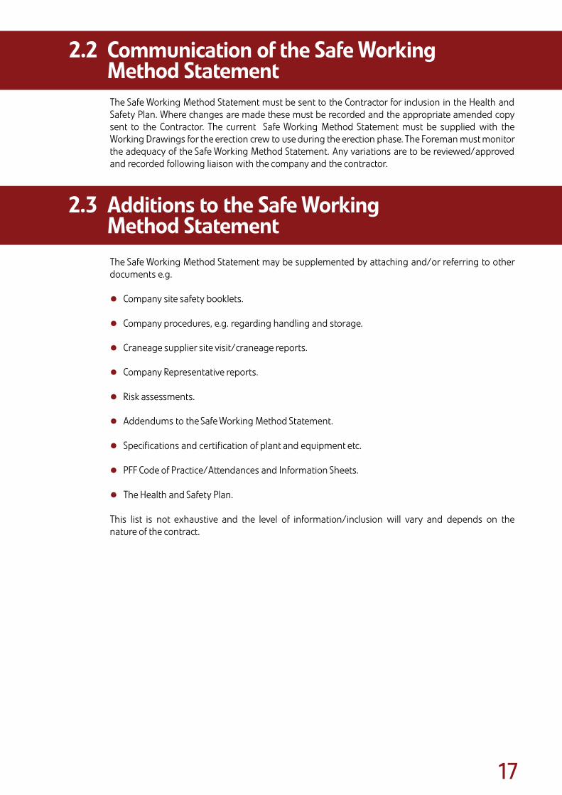
The Safe Working Method Statement must be sent to the Contractor for inclusion in the Health and Safety Plan. Where changes are made these must be recorded and the appropriate amended copy sent to the Contractor. The current Safe Working Method Statement must be supplied with the Working Drawings for the erection crew to use during the erection phase. The Foreman must monitor the adequacy of the Safe Working Method Statement. Any variations are to be reviewed/approved and recorded following liaison with the company and the contractor.
The Safe Working Method Statement may be supplemented by attaching and/or referring to other documents e.g.
• Company site safety booklets.
• Company procedures, e.g. regarding handling and storage.
• Craneage supplier site visit/craneage reports.
• Company Representative reports.
• Risk assessments.
• Addendums to the Safe Working Method Statement.
• Specifications and certification of plant and equipment etc.
• PFF Code of Practice/Attendances and Information Sheets.
• The Health and Safety Plan.
This list is not exhaustive and the level of information/inclusion will vary and depends on the nature of the contract.
2.2 CommunicationoftheSafeWorking MethodStatement
2.3 AdditionstotheSafeWorking MethodStatement
1�
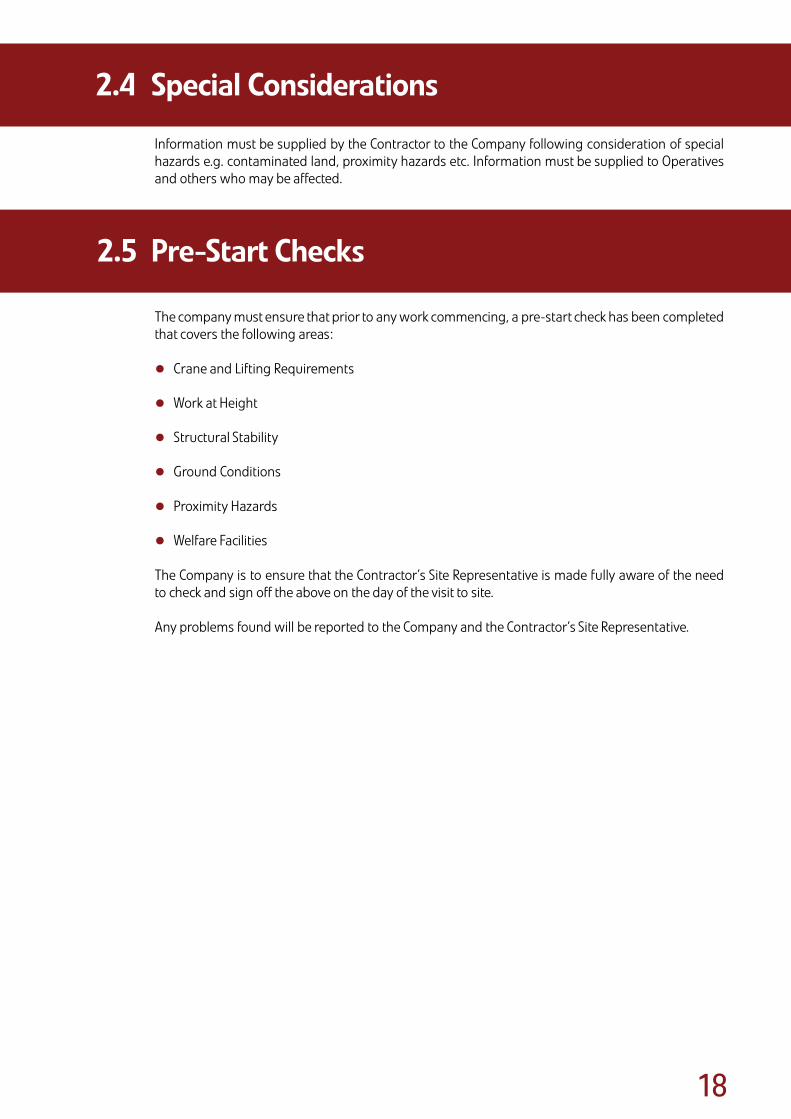
Information must be supplied by the Contractor to the Company following consideration of special hazards e.g. contaminated land, proximity hazards etc. Information must be supplied to Operatives and others who may be affected.
The company must ensure that prior to any work commencing, a pre-start check has been completed that covers the following areas:
• Crane and Lifting Requirements
• Work at Height
• Structural Stability
• Ground Conditions
• Proximity Hazards
• Welfare Facilities
The Company is to ensure that the Contractor’s Site Representative is made fully aware of the need to check and sign off the above on the day of the visit to site.
Any problems found will be reported to the Company and the Contractor’s Site Representative.
2.4 SpecialConsiderations
2.5 Pre-StartChecks

Section 3:Training and Certification
The PFF is committed to ensuring that all Erectors involved in erection activities carried out by its member companies are competent. This includes ensuring a good understanding of the objectives of this PFF Code of Practice for the Safe Erection of Precast Concrete Flooring.
The Company should determine the level of training an individual has achieved and should provide training, instruction and refresher trainingas required.
Precast Flooring Federation
Sect
ion
3
Dividers.indd 3 9/6/08 15:52:44
�0
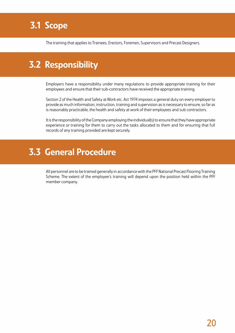
The training that applies to Trainees, Erectors, Foremen, Supervisors and Precast Designers.
Employers have a responsibility under many regulations to provide appropriate training for their employees and ensure that their sub-contractors have received the appropriate training.
Section 2 of the Health and Safety at Work etc. Act 1974 imposes a general duty on every employer to provide as much information, instruction, training and supervision as is necessary to ensure, so far as is reasonably practicable, the health and safety at work of their employees and sub contractors. It is the responsibility of the Company employing the individual(s) to ensure that they have appropriate experience or training for them to carry out the tasks allocated to them and for ensuring that full records of any training provided are kept securely.
All personnel are to be trained generally in accordance with the PFF National Precast Flooring Training Scheme. The extent of the employee’s training will depend upon the position held within the PFF member company.
3.1 Scope
3.2 Responsibility
3.3 GeneralProcedure

�1
The training of personnel at all levels is to be carried out by competent persons or approved training organisations (e.g. CPCS/CITB/Proskills). Courses may include those in the following list, which is not exhaustive:
• Site safety awareness.
• Manual handling.
• Power cut-off/abrasive wheel operation.
• Work at height/work at height equipment.
• PFF Code of Practice for the Safe Erection of Precast Concrete Flooring.
• Slinger/Signaller.
• Crane Supervisor (BS 7121).
• Appointed Person (BS 7121).
• MEWP (mobile elevated work platform) scissor and boom operation.
• Fork lift/tele-handler operation.
• Passive fall installation.
• CDM regulations.
In addition it is recommended that each team of Erectors has a suitably qualified person to administer emergency aid or a fully qualified First Aider. The employer’s duty to provide first aid is set out in Regulation 3(1) of the Health and Safety (First-Aid) Regulations 1981 “An employer shall provide, or ensure that there are provided, such equipment and facilities as are adequate and appropriate in the circumstances for enabling first aid to be rendered to his employees if they are injured or become ill at work”.
Note
Re-training must be regularly monitored; no employee can remember everything, especially if it is not an everyday part of the individual’s work. The need for re-training is an essential requirement to satisfactorily meet the requirements of the current regulations. Re-training requirements can be monitored by expiry dates on certificates of achievement or by periodic assessment of individuals followed by refresher training.
The above training is the responsibility of the Company employing the Erector and other Operatives.
Trained and competent Operatives should hold the following competency cards in accordance with the Construction Skills Competency Scheme (CSCS) and the Construction Plant Competency Scheme (CPCS):
• CSCS Precast Concrete Installer (Industry Accreditation A) card.
• CPCS Slinger/Signaller card.
Operatives who have not achieved this card should receive appropriate training and carry out the following NVQ’s which will enable them to achieve the appropriate competency card:
• NVQ in Precast Concrete Installation.
• NVQ in Slinger/Signalling.
3.4 Training
3.5 Certification/Competency

Section 4:Design Considerations
Installing precast concrete floors is a high-risk activity, which usually involves Operatives and Erectors working at heights and the use of cranes. To assist Engineers, Designers, Contractors and CDM Co-ordinators in meeting the requirements of the CDM, the following detailed information is provided to assist in co-ordinating designs to achieve safe erection.
In the text that follows the Precast Designer is not the Building Designer(see definitions on page v and vi).
Precast Flooring Federation
Sect
ion
4
Dividers.indd 4 9/6/08 15:52:44

��
The following aspects should be investigated:
• The sizes and weights of the components will determine the method of off-loading and placing the units. • The precast units are usually delivered to site on articulated lorries; narrow roads or restricted access may necessitate the use of rigid lorries. • Pedestrian and traffic management measures need to be considered, especially if the delivery lorries are offloaded from the public highway. In this case the Contractor must ensure that any actions taken comply with The New Roads and Streetworks Act 1991.
• The Contractor should consider the Traffic Management Plan, other trades and deliveries, and plan adequate arrangements for offloading positions and fall protection equipment around vehicles.
• Adequate access to the work area must be provided for cranes and lorries and hardstanding must be provided to safely support the loads imposed by the crane’s outriggers.
• Excavations, underground services, drains and basements are a hazard and strengthening may be required.
• The presence of power lines, railway tracks, trees or overhead structural obstructions may hinder the operation of cranes.
• On restricted sites it may be necessary for loads to be lifted over adjacent land and buildings. In these circumstances, permission must be obtained to operate within the airspace of third parties.
The Regulations require that a Designer’s competence has to be considered in the light of health and safety. Members of the PFF can demonstrate their experience and competence in the design and manufacture of precast flooring.
To assist the Precast Designer, the following information should be provided at tender stage:
• Pre-tender stage Health and Safety Plan.
• Design loads including finishes and imposed loads.
• Drawings showing the supporting structure for the precast units and direction of span.
• Phasing or sequencing of the works.
• Site and services plan.
InformationFollowingOrder
When an order is placed for the precast concrete units, the Contractor should provide the Precast Flooring Company with the following information:
• Any relevant amendments to the Health and Safety Plan.
• Fully dimensioned “Construction Issue” drawings, detailing the supporting structure for the floors and any other aspects that may affect the floor design and installation.
• Loadings, including type and location of partitions, types of finish, etc.
• Position and sizes of all holes, notches or rebates required in the flooring.
• Site and services plan (if not provided at tender stage).
• Provisional sequencing and programme dates.
• Where working in the vicinity of rail tracks, underground railway lines, or energy supply structures such as power cables, all permissions that are required from the owners or controllers of the relevant infrastructure are to be given in advance, along with any special instructions for the safe installation of the works.
4.1 TheExistingEnvironment
4.2 DesignandPlanning
4.2.1
��
StabilityoftheStructureDesigners must take into account the stability of the structure during the installation of precast units:
• The building design should allow for the removal, prior to the installation of the units, of overhead obstructions, such as purlins, bracings or main beams (where spans change at the level above) that are likely to foul or hinder the crane boom or suspended load.
• Precast units are heavy. Bearings must be adequate and be robust enough to withstand normal unit fixing operations including landing and barring.
• Lintels or steel beams must be securely fixed and have adequate safe bearing at each end to avoid overturning, excessive deflection, or collapse when the precast units are placed.
• Consideration must be given to the unequal loading of unrestrained walls, lintels or steel beams when precast units are being placed.
• The practice of erecting precast units onto temporary bearings must be avoided wherever possible.
• In cases where such measures are unavoidable the temporary bearings must be designed and erected by a competent person (provided by the Contractor).
The installation of precast concrete units should be undertaken only by competent precast companies/Erectors. Members of the PFF only employ Erectors who are trained, competent and experienced in this work.
The Contractor must ensure that the PFF Standard Health, Safety and Welfare Attendances have been provided.
Installing precast concrete floors is a high risk operation and should not be undertaken without the provision of a job specific method statement and risk assessments which should address some or all of the following activities:
• Manual handling.
• Working at heights with risk of personnel/objects falling.
• Working with cranes.
• Handling or cutting concrete products.
• Working with wet concrete/mortar.
The Contractor must ensure that other trades and the public are kept out of the working area covered by cranes used for installing the precast units.
A major consideration for the Building Designer and Contractor should be the stability of the structure during the installation of the precast concrete units.
Time must be allowed for masonry mortar to mature sufficiently to achieve adequate strength and stiffness (special consideration must be given to retarded mortar).
The Building Designer must give consideration to the provision of adequate wall thickness, particularly where shared bearings occur on lightweight masonry blocks.
The Building Designer and the Precast Designer must give consideration to the proposed sequence of construction and the effects of any temporary removal of parts of the structure to facilitate the safe installation of the precast units.
A period of 72 hours should be allowed for a grouted floor to mature prior to loading out with materials, which should not exceed the load for which the floor has been designed. Advice and approval should be sought from the Company prior to the storage of unfixed materials on the floors by following trades.
4.2 DesignandPlanning
4.3 ConstructionPhase
4.2.2

��
As a prime consideration at the design stage, the Building Designer and the Company must pay attention to the on site practices of handling precast units and their erection sequence.
Areas of precast units, both collectively and individually, must be so designed and detailed as to allow for adequate and safe handling, including safe means of removing lifting tackle after units have been placed.
Particular attention must be given where units may need to be tilted or twisted into position (ledger angles or similar). The Building Designer and Precast Designer must assess the suitability and adequacy of supports. Careful consideration must be given to ensure that there is sufficient clearance to place the unit whilst still achieving the minimum end bearing required when the unit is in its final position.
The Building Designer must ensure that all working drawings and specifications convey any special design requirements to the Installer, such as special fixing techniques or sequence of work, or temporary measures, e.g. braces, props. This information should be incorporated onto the Installers erection drawings by the Precast Designer.
Cantilevers do not usually present a problem. However, if units are to be installed to a cantilevered area of flooring, then the design, and working drawings, must pay attention to counterbalances, and the sequence in which these are to be installed. Any propping that may be necessary during construction must also be clearly indicated on the erection drawings (including at what stage in the installation process) and must be designed and erected by competent persons provided by the Contractor.
The cantilever end of any precast member must also be distinctly marked on the unit to avoid incorrect fixing.
4.4 Lifting,PlacingandSafeHandlingofUnits

��
The following good practice applies to all types of blockwork used in construction of cavity walls:
• In all installations, where the inner leaf of the cavity is less than 190mm thick, it is recommended that the outer leaf is constructed to within 225mm of the bearing height of the inner leaf. This is so that maximum stability can be achieved during the construction phase. (Figure 4.1 see next page).
• The top bearing course should be constructed with full blocks and not cut or coursing blocks unless the flooring system is specified using coursing blocks as part of the system.
• Inner non-loadbearing walls should be left one course down to assist with the positioning of the flooring system in the construction phase.
• With all mortars, sufficient curing time must be allowed so that the supporting structure achieves sufficient strength. Care should be taken, especially in inclement weather conditions, in the use of retarded and lime mortar. Reference should be made to the manufacturer’s data sheet on the mortar product.
• Pressed steel lintels must be installed in accordance with the lintel manufacturer’s recommendations. They should be bedded onto a full block and the blockwork should be set out to avoid vertical joints lining up in adjacent courses (Figure 4.6).
• Lintels over openings of 900mm or above should be propped at centres of no morethan 600mm to prevent the lintel from deflecting and rotating during the construction phase (Figure 4.2 see next page).
• Steel section lintels should be firmly fixed to padstones set onto the blockwork. Ties down the wall should be used in vulnerable conditions such as isolated piers. Where it will be loaded unequally,the lintel may require additional temporary support to prevent rotation during the erection of precastfloor units (Figures 4.3 and 4.4).
• All wall ties must be in place and installed in accordance with the relevant standards or code.
• Narrow sections of walls (less than 900mm) or piers should be given special consideration as these can be weak points during the construction phase. The Building Designer may need to consider additional temporary support.
• The bearing surface should be clean, level and free from mortar snots.
• Where an internal load bearing wall intersects with other load bearing walls, the joints must be fullybonded or tied in.
GeneralNotesfortheBuildingDesigner:
• Cement mortars - Allow 3 to 7 days for masonry to cure before loading out.
• Lime and retarded mortars - Always check curing times with manufacturer or supplier.
Remember, in poor curing conditions adequate design strength will take longer to achieve.
4.5 InstallationofPrecastConcreteFloors onMasonry
4.5.1

��
225mmmax
Gre
ater
than
225m
m
Lintel
Prop
Figure4.1
Figure4.2
Figure4.3
Correct
Correct
Incorrect
Incorrect
Cav�ty wall construct�on outer sk�n must be bu�lt up to w�th�n ���mm of �nner sk�n to ma�nta�n stab�l�ty.
L�ntels (‘top hat’ or pressed steel)
For open�ngs of �00mm or more, the �nner sk�n should be propped at centres of no more than �00mm to prevent the l�ntel from deflect�ng and rotat�ng dur�ng the construct�on phase.
L�ntels should be des�gned w�th the construct�on phase load�ng �n m�nd, as th�s type of l�ntel does not ach�eve full load capab�l�ty unt�l construct�on �s complete.
Steels should be firmly fixed to padstones set onto the blockwork.
T�es down the wall should be used �n vulnerable cond�t�ons such as �solated p�ers. Where �t w�ll be loaded unequally, the l�ntel may requ�re add�t�onal temporary propp�ng to prevent rotat�on.

��
Fixings
Propped
Steel section can rotate due tolack of torsional restraint
Lintel overopening
Joints incorrect - resulting in linethrough which failure could occur
Blocks split at bearing levelBearinglevel
At least 75mm
Lintel overopening
Full width blocksBearinglevel
Lateral restraint totop of wall
Load bearing wall lessthan 190mm wide
Timber belowbearing level
Props to provide lateral stabilityto single skin load bearing wall(provided by the contractorprior to installation).
Figure4.4
Figure4.5
Figure4.6
Correct
Correct
Incorrect
Incorrect
Temporary props or other means of bear�ng enhancement should be employed, des�gned and erected by competent persons (other than the floor�ng �nstaller).
T�mber runners should be pos�t�oned approx�mately �mm below bear�ng level and �n t�ght contact w�th each s�de of the wall to prov�de full lateral support. The props and t�mber runners should also be des�gned to �ncrease bear�ng w�dth and carry the floor react�on �n the event of a bear�ng fa�lure.
Steel bear�ng plates may be �ntroduced to �ncrease the bear�ng w�dth. Th�s may om�t the need for rak�ng lateral support props. Vert�cal propp�ng w�ll st�ll be requ�red each s�de of the wall beneath the extended plate to prevent potent�al rotat�on. The
plate should also be fixed us�ng countersunk fix�ngs and la�d on a mortar bed to avo�d po�nt load�ng the wall. It �s �mportant that the Erector �nstalls the end of the floor slab to the centre of the wall and does not just load the end of the steel plate, wh�ch would cause �nstab�l�ty.
Thesteelplateandappropriateproppingaretobedesigned& erected by competent persons (other than the flooringinstaller).
On beam and block floor�ng, propr�etary ‘T-Beam butt plates’ may be used wh�ch must be des�gned by a competent person g�v�ng cons�derat�on to the need for propp�ng.
L�ntels should always bear on full blocks
Isolated steels must be fixed and temporary propp�ng should also be �ncorporated where the ‘fixed’ steel beams are l�kely to tors�onally deflect dur�ng erect�on of the precast floor un�ts.
The ‘perp’ jo�nts between masonry un�ts should be staggered at least ��mm
Correct Incorrect

��
In addition to the self-weight of the floor units, other loads may be imposed during the erection operation. These loads must be anticipated at the design stage and be considered when selecting unit types and layouts.
With beam and block systems, the weight of blocks being loaded for installation must be assessed and any prohibitions or special requirements to accommodate such loads, must be clearly indicated by the Precast Designer.
When screeds or structural toppings are required, the imposed loads must be anticipated by both the Building Designer and the Precast Designer and special provisions clearly noted.
Design loadings for the floor are stated on the drawings and must not be exceeded during the construction works. Approval should be sought from the Company prior to the storage by following trades of unfixed materials on floors.
The stability of the supporting structures must not be adversely affected by the installation of precast flooring and components, including temporary stacking on the floors.
If the removal of any structural member is necessary to facilitate the installation, structural stability must be maintained and the Building Designer must liaise with relevant Engineers, Contractors and Sub-contractors. The Contractor is responsible for the removal and replacement operations, by way of an Attendance, to ensure the safe installation of the precast units.
Where it can be anticipated that stability will not be guaranteed, as in the case of temporarily propped or jacked floors, a safe system of work must be developed to keep the structure within the safe limits allowable. The following must also be considered: All temporary works must have been sufficiently designed and installed by competent persons provided by the Contractor.
When designing bearings, consideration must be given to the standard method of fixing precast concrete components, particularly the method of final alignment. Construction loading arrangements/forces may be more onerous than the final working condition. The Building Designer must take into account manufacturing and construction tolerances to ensure minimum bearings are achieved.
The Building Designer must undertake an assessment of the risks likely to occur during installation of the precast flooring/component and any apparent instability issues relating to the supporting structure. Advice and approval may be sought from the Precast Designer on these matters.
HandrailstoStairsandLandingsIt is considered best practice for the Building Designer to specify a type of handrail and the method of fixing the handrail to a stair flight and landing before the flight or landing are lifted into their final position.
The installation of the handrail will therefore be carried out from a safer position i.e. ground level on site, avoiding the need to work at height, and the stairs can be immediately used for safe access and egress to different levels. However, it is recognised that this is not always achievable.
Careful planning at pre-contract and design stage will be required by the Contractor. The Contractor should liaise with the Precast Installer / Precast Designer and consider the following points to ensure that the specified method is practical and agree arrangements:
• Can the stairs and landings be safely lowered into position with the handrails attached?
• Can the handrails be adequately secured for safe lifting into position?
• Will the handrails on the erected units clash with any subsequent fall protection required at higher levels?
• Contractor to arrange work so that it is carried out to the agreed sequence of erection.
• Contractor to co-ordinate other trades to be in attendance as required, i.e. Scaffolder.
• Position of fixing and design of fixing for handrails to be agreed with the Precast Designer.
• Contractor to ensure that the concrete finish, after filling of any holes has been agreed with the appropriate Building Designer/Specifier.
4.6 ImposedLoadsDuringthe ConstructionPhase
4.7 StabilityofSupportingStructure DuringtheConstructionPhase
4.7.1

�0
• The Company will provide ‘as installed’ drawings at completion of the installation, showing any changes from the original floor layout. Thereafter, the Contractor will be responsible for recording departures from these drawings.
• The flooring layout drawings will detail the loads for which the floors have been designed.
• Care should be exercised to ensure that during both the construction phase, and during the life of the building, the design loads are not exceeded and that further holes or chases are not made in the flooring without reference to the Company.
• Advice and approval on demolition should be sought from a competent person, with access to the Health and Safety File.
Thefollowingaresomeoftheconstructionpractices,investigatedbytheHealthandSafetyExecutive,whichhavebeenpartiallyresponsibleforaccidentsoccurringonsiteswhereprecastcomponentshadbeeninstalled.
• Masonry support bearing details for lintels and slab/beam units which were not in accordance with the working drawings and which had not been checked by any site supervisor.
• Pressed steel lintels that had been loaded with precast units in advance of being adequately supported.
• Masonry support bearing details where freshly laid, uncured mortar, often retarded mortar, has had loadings placed upon them.
• Unstable and inadequate masonry bearing details which were in accordance with the working drawings but which had been poorly designed without appreciation of the temporary condition during construction.
• Beam and block flooring units left ungrouted/unscreeded for a significant period of time resulting in the block support bearings becoming inadequate in width (due to movement of the beams) and a collapse occurring.
• Installers carrying out precast slab barring operations without inspecting and checking the bearing supports onto which they were placing their components.
• Installers supervisors not having sufficient authority to stop their work if they were concerned over the adequacy of the provided bearings.
The principles of prevention and protection must be applied to all risks and the design should be governed by what is reasonable and practical. Any remaining areas of risk should be clearly communicated to the Company Representative.
4.8 TheHealthandSafetyFile
4.9 PoorBuildingPractices

Section 5:Contractor’s Responsibilities
Precast Flooring Federation Se
ctio
n 5
Dividers.indd 5 9/6/08 15:52:44
��
The flooring sub-contractor will provide the Contractor with a copy of the PFF Health, Safety and Welfare Attendances (Appendix A), attached to the Company’s quotation. These, together with any additional specific requirements necessitated by the nature of the site or contract works, are to be provided by the Contractor.
The Contractor must also maintain and upgrade these attendance items to compensate for deterioration through usage and weather.
The Contractor must familiarise themselves with the safety aspects of precast concrete installation works by reading this Code of Practice and taking note of issues raised by the Company Representative during the pre-start site visit.
The Contractor is responsible for ensuring that guidance within this Code of Practice is incorporated into works by other trades and where necessary the guidance of the Building Designer and other specialist suppliers/sub-contractors is incorporated into the works.
The Contractor is deemed to accept responsibility for the protection of precast units from the time when the physical installation of the sub-contract works, or any section thereof, has been completed, unless otherwise agreed.
At the time when the precast flooring Installers leave the site, the grouting (where applicable) will generally be in an ‘uncured’ condition. Whilst the grout is not always structural, it is recommended that a minimum curing period of 72 hours should be allowed. During this time the floor may require weather protection, the provision of such protection being the responsibility of the Contractor.
In most cases damage sustained to flooring units is caused by impact during the progression of following trades. Other damage that frequently occurs is caused by cutting and drilling the precast concrete units; this must not happen without first consulting the Company.
The Contractor is responsible for the upkeep, adaptation and final removal of the handrailing to ensure that protection is maintained for all subsequent operations.
5.1 Attendances
5.2 ManagementofConstructionWorks
5.3 PreventionofDamagetoPrecastUnits
5.4 HandrailingtoPrecastStairUnits

Section 6:Company Representative’s Role
Prior to any installation work, the Company Representative will visit the site to identify any site specific hazards and establish a safe system of work in agreement with the Contractor.
Precast Flooring Federation
Sect
ion
6
Dividers.indd 6 9/6/08 15:52:44

��
The Company Representative will liaise with the Contractor at the site to agree the sequence in which precast units are to be erected, with reference to building plot numbers, floor levels, flat or house types, grid references etc. Should it be necessary for the installation sequence to be varied, for whatever reason, this should only be implemented after reference to the Company, Contractor and Building Designer, and after all safety requirements have been satisfied. If deemed necessary, the Safe Working Method Statement should be amended by an addendum to cover the revision agreed.
The Company will provide the Appointed Person for lifting operations , unless otherwise agreed, according to training, knowledge and experience. If necessary, in liaison with crane hire representatives, the Company Representative will decide upon the type of lifting plant and equipment to be employed in the installation of each specific contract, taking into account the weight of components to be lifted, the radius of lifting, and any special handling requirements.
The Contractor and the Appointed Person will discuss and advise upon the type and size of delivery lorries and craneage, in order that the Contractor may provide adequate access and hardstandings, or other facilities that may be required to accommodate delivery and lifting equipment.
The Appointed Person must also bring to the attention of the Contractor any factors likely to hinder the lifting operations e.g. aerial obstructions, proximity hazards, stacked materials or earthworks, in order that a safe system of work and/or control measures can be agreed.
After reaching a decision upon the lifting arrangements, the Appointed Person should provide a record, including the agreed hardstanding positions, ground bearing pressure requirements, roadways, agreed offloading positions and any storage areas. A duplicate should be handed to the Foreman before work is commenced.
If at any time subsequent to the Company’s initial choice, the design is altered so causing component weights to vary from those originally envisaged, the Precast Designer must inform the Appointed Person who must ensure that the crane or lifting equipment is still adequate.
During the routine pre-contract visit, the Appointed Person must ensure that the site constraints observed or anticipated at the time when the crane or lifting equipment was selected, have not changed and will not change. If change has occurred, or can be anticipated, the Appointed Person must again ensure that the crane or lifting equipment is adequate. The Contractor and Building Designer must be notified of any changes.
It is the Contractor’s responsibility to ensure the provision and maintenance of suitable ground bearingconditions for the planned lifting operations.
In any instance where the crane or lifting equipment is changed from the original, the Appointed Person must advise the Contractor’s Site Representative of such change, in order that access, standing areas, or other measures may be amended if deemed necessary by the Contractor.
If the Contractor provides the craneage (i.e. tower crane) and lift planning, he must also provide an Appointed Person for the lifting operations. The Company Representative must provide the Contractor with all relevant information e.g. component weights and agree offloading positions.
6.1 AgreedSequenceofInstallation
6.2 MethodofLifting

��
The Company must agree with the Contractor the access from the public highway onto site, including the possible need for temporary or long term removal of any fences, walls or other obstructions. See also: Appendix A, Section 1 paragraphs 5 and 6.
The condition of the agreed access roads must at all times be maintained by the Contractor to an acceptable standard.
Whilst making these arrangements the locations of and access to, stacking areas, stores, temporary buildings and lorry/trailer holding areas must be agreed.
On agreement of the provisions, a written record must be issued to the Contractor. The agreed access and other arrangements must then be incorporated into the Work Method Statement, in order that all parties will have the information readily available and to avoid misunderstandings or confusion when the floor installation commences.
Access into the building(s) as construction progresses must be agreed together with protection on and around the flooring in accordance with the requirements of the PFF Standard Health, Safety and Welfare Attendances, issued at tender stage. Particular attention should be paid to barriers, guardrails / handrails, toe-boards, access, lighting and similar precautions. The Company must monitor the provision of these Attendances during the period of the site works.
The Contractor will be aware of the Company’s general requirements with regard to Attendances, having received the PFF Health, Safety and Welfare Attendances as specified in Appendix A.
The Company Representative should discuss the general requirements with the Contractor in order to agree more specific Attendances that reflect the nature of the site and the contract works.
All agreements reached between the Company Representative and the Contractor’s Site Representative must be confirmed either in writing or by inclusion on a marked-up record, copies being held by both parties to the agreement.
Prior to the precast component installation, the Contractor should ensure the suitability of bearings provided for the flooring, in accordance with the construction drawings and this Code of Practice.
Where appropriate, the Company may require the Company Representative to be present on site to assist with the periodic supervision of the installation team.
Where the Appointed Person has determined that the general lifting operations are basic or standard, the Appointed Person’s duties can be delegated. The person to whom those duties are delegated will then assume the duties of Crane Supervisor.
6.3 SiteAccess
6.4 AttendancesLiaison
6.5 SupervisionofInstallation
Section 7:Foreman’s Role
Precast Flooring Federation
Sect
ion
7
Dividers.indd 7 9/6/08 15:52:44

��
Prior to the arrival of the installation team a sequence of on site installation must have been agreed, in the form of a Safe Working Method Statement with records kept on site and a copy handed to the Foreman.
It is the responsibility of the Foreman to ensure adherence to the agreed sequence. In circumstances where a deviation from the sequence is unavoidable, the Foreman must seek advice and approval before altering the sequence, either by referring back to the Company, or to the Company Representative responsible for that contract.
Before commencing the installation of any precast units, the Foreman must satisfy himself that the Attendances agreed for that contract are available and of a satisfactory standard in accordance with the Safe Working Method Statement. Where possible such a pre-start check should be conducted together with the Contractor’s Site Representative.
If any item is found to be inadequate or missing, the Foreman must highlight the problem and, if necessary, delay the installation until Attendances are satisfactory. In such circumstances, the Foreman must fully acquaint his head office with the situation.
The Foreman must ensure, by inspection prior to the installation, that the bearings provided for the precast units (including those on steelwork) are visually satisfactory. It is preferable, and contractually prudent, that the Foreman should be accompanied by the Contractor’s Site Representative during these inspections. However, it is essential that the Foreman carries out these inspections, and reaches his decisions based on his inspections regardless of the presence or the absence of the Contractor’s Site Representative.
The Foreman should ensure any deviation from the provision of fall protection detailed in the safe working method, is reviewed, approved and documented by the Company prior to implementation.
The Foreman may be delegated by the Appointed Person to assume the duties of Crane Supervisor when it has been determined that the general lifting operations are basic or standard. The Foreman to whom those duties are delegated will then assume the duties of Crane Supervisor.
In all cases, the Foreman is responsible for the actual installation of the precast units. On contracts where the Company Representative oversees the installation, the overall responsibility for the installation team and their actions still remains with the Foreman. The Company Representative should give instructions to the Foreman only.
The delegation of specific tasks within the team is the responsibility of the Foreman, who must be satisfied that the person to whom the task is assigned is competent to carry out that work safely.
Before placing any units the Foreman must ensure that the crane (where applicable) is operating in a safe and proper manner, and that the Crane Operator is fully aware of the nature of the work and can identify and understand the Slinger/Signaller.
Where the Foreman has concerns regarding the adequacy of the bearings and/or the structural integrity of the building, then he must seek advice and instruction from the Precast Designer. If the bearings are considered satisfactory by the Precast Designer, then the bearing detail needs approval from the Building Designer before work can proceed and amended details should be issued. If the bearings are not considered satisfactory by the Precast Designer, then the bearings should be amended by the Contractor to accord with the approved details.
7.1 WorkingtoSequence
7.2 Pre-startCheck
7.3 SupervisionofInstallation

��
During the course of the installation, the Foreman must check the quality of bearings and any variation or deterioration, from whatever cause, must be brought to the attention of the Contractor’s Site Representative. Work must be suspended if the bearings become unacceptable.
During the installation of the precast units the Foreman must ensure that correct handling and placing procedures are being adhered to, and that all aspects of the work are being executed in a safe and proper manner, in accordance with the Safe Working Method Statement and Working Drawings.
The Foreman must also check the dimensional accuracy of the individual units and the accuracy of setting out of the floor, ensuring that all units correspond with the Working Drawings.
No variations to the design or design details and no remedial works should occur without the prior approval of the Precast Designer and the Building Designer. No change to the construction method or sequence should occur without the prior approval of the Precast Designer, the Building Designer, the Contractor and the Company Representative.
When the installation of the floor is complete or any section of the floor which that visit covers, the Foreman together with the Contractor’s Site Representative should physically inspect the work. Should any damaged or improperly fixed components be present, these should be replaced or repaired as soon as is reasonably practicable, after reference by the Foreman to his Company.
The Foreman must also co-ordinate and monitor other site personnel involved with the precast installation works, such as fall protection Operatives and delivery drivers.
Units must be fixed strictly in accordance with the Working Drawings.
No ‘unspecified’ works of any type including remedial works should be carried out without the prior approval of the Precast Designer, the Building Designer, the Contractor and the Contractor’s Representative. If approved and carried out, it must be recorded by the Company.
The Foreman must ensure that the work area is kept clean and tidy, so far as this is reasonably practicable and at the end of the working day the area should be left free of debris. Materials must be safely stacked.
After the floor is laid, the Foreman will advise the Contractor’s Site Representative that the work is completed and request an inspection prior to leaving site. During this period a checklist will be completed and a copy will be left on site.
7.3 SupervisionofInstallation
7.4 Workmanship
Section 8:Transportation of Components and Access to Site
Precast Flooring Federation
Sect
ion
8
Dividers.indd 8 9/6/08 15:52:45

�0
The fundamental concerns when loading delivery vehicles must be to ensure an even weight distribution and load stability.
When considering the loading of precast components, it is important that the loading arrangements allow the maximum protection against damage or breaking. Slabs that have detail, such as holes or cut widths, may need to be placed at the top of the load to avoid damage during transportation.
Components must have bearers placed at correct positions along their length, in accordance with the Company’s recommendations. Where components are stacked in layers of more than one high, the bearers to each layer should line through vertically, to avoid shear planes.
When loaded the units must be properly and adequately secured to the vehicle, to prevent movement during transit, particular attention being paid to loose items. Measures must be taken to prevent individual concrete blocks or fragments and angles or timber falling from the vehicle.
From the point of view of safety during the installation operation, it is important that components are loaded so that unloading may be carried out in appropriate sequence. However, this must never be at the expense of the safe transit of the complete load and therefore some double handling may be required at the point of installation.
Before a vehicle arrives on site, the access from the highway onto and around the site should have been agreed between the Company Representative and the Contractor, taking into account the site traffic management plan. The Foreman should have checked access suitability with the Contractor’s Site Representative upon site commencement.
A nominated member of the installation team should act as Signaller to supervise and assist in the positioning of the delivery vehicle both on and off site.
Notwithstanding the above, the final acceptance of the access suitability will remain with the vehicle driver, and in these circumstances the driver must satisfy himself before entering the site that his vehicle can travel safely on the access provided.
In all cases the driver must not remove any securing ropes, chains or tarpaulins, until his vehicle is at rest in the area agreed for unloading.
8.1 TheStackingandMakingSecureofLoads
8.2 LoadingSequence
8.3 SiteAccess
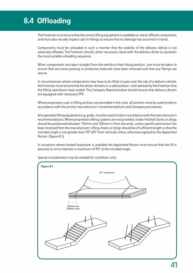
�1
The Foreman must ensure that the correct lifting equipment is available on site to offload components and must also visually inspect cast-in fittings to ensure that no damage has occurred in transit.
Components must be unloaded in such a manner that the stability of the delivery vehicle is not adversely affected. The Foreman should, when necessary, liaise with the delivery driver to ascertain the most suitable unloading sequence.
When components are taken straight from the vehicle to their fixing position, care must be taken to ensure that any loose packing or protective materials have been removed and that any fittings are secure.
In circumstances where components may have to be lifted or pass over the cab of a delivery vehicle, the Foreman must ensure that the driver remains in a safe position, until advised by the Foreman that the lifting operations have ended. The Company Representative should ensure that delivery drivers are equipped with necessary PPE.
Where proprietary cast-in lifting anchors are provided in the units, all anchors must be used strictly in accordance with the anchor manufacturer’s recommendations and Company procedures.
Any specialist lifting equipment e.g. grabs, must be used strictly in accordance with the manufacturer’s recommendations. Where proprietary lifting systems are not provided, choke-hitched chains or slings should be positioned between 150mm and 300mm in from the ends, unless specific permission has been received from the manufacturer. Lifting chains or slings should be of sufficient length so that the included angle is not greater than 90º (45º from vertical) unless otherwise agreed by the Appointed Person (Figure 8.1).
In situations where limited headroom is available the Appointed Person must ensure that the lift is planned so as to maintain a maximum of 90º at the included angle.
Special consideration may be needed for cantilever units.
8.4 Offloading
150mm min300mm max
90 ° maximum
Figure8.1

��
Every precast floor, balcony or stair unit, must be inspected before lifting from the delivery transport and/or stockpile on site for obvious signs of damage e.g. cracking, damage around holes/notches and other physical damage. Where a unit is deemed to be damaged the Foreman must telephone the Company for advice, contacting a person competent to make the decision, on what action should be taken in respect of the damaged unit.
Before removing chains, components must be measured to ensure that the correct bearing can be achieved and the Company contacted in any case when the Foreman is in doubt.
A further visual inspection must also take place after the units have been installed and before the area is handed over to the Contractor. In addition to the defects considered above, a check must also be made to ensure that all units have adequate bearing and that all areas have been sufficiently grouted.
8.5 InspectionofPrecastConcreteFlooring andotherComponentsPriortoInstallation.
Section 9:On Site Storage of Components
Precast Flooring Federation
Sect
ion
9
Dividers.indd 9 9/6/08 15:52:45
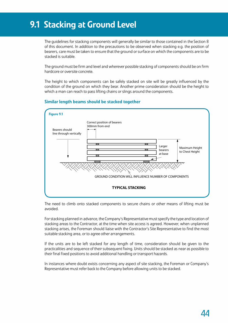
��
The guidelines for stacking components will generally be similar to those contained in the Section 8 of this document. In addition to the precautions to be observed when stacking e.g. the position of bearers, care must be taken to ensure that the ground or surface on which the components are to be stacked is suitable.
The ground must be firm and level and wherever possible stacking of components should be on firm hardcore or oversite concrete.
The height to which components can be safely stacked on site will be greatly influenced by the condition of the ground on which they bear. Another prime consideration should be the height to which a man can reach to pass lifting chains or slings around the components.
Similarlengthbeamsshouldbestackedtogether
The need to climb onto stacked components to secure chains or other means of lifting must be avoided.
For stacking planned in advance, the Company’s Representative must specify the type and location of stacking areas to the Contractor, at the time when site access is agreed. However, when unplanned stacking arises, the Foreman should liaise with the Contractor’s Site Representative to find the most suitable stacking area, or to agree other arrangements.
If the units are to be left stacked for any length of time, consideration should be given to the practicalities and sequence of their subsequent fixing. Units should be stacked as near as possible to their final fixed positions to avoid additional handling or transport hazards.
In instances where doubt exists concerning any aspect of site stacking, the Foreman or Company’s Representative must refer back to the Company before allowing units to be stacked.
9.1 StackingatGroundLevel
Bearers shouldline through vertically
Correct position of bearers300mm from end
Largerbearersat base
Maximum Heightto Chest Height
GROUND CONDITION WILL INFLUENCE NUMBER OF COMPONENTS
TYPICAL STACKING
Figure9.1

��
Unfixed components should be stacked at ground level but, on sites with limited space, or where the type of construction does not allow stacking at ground level, components may have to be temporarily stored on top of the incomplete floor or previously fixed components.
Where this is to occur the Precast Designer and Building Designer must take due consideration of the resulting imposed loads, and the stability of the structure, especially lintels over openings. This action will be the subject of a Design Risk Assessment and Safe Working Method Statement prior to the commencement on site by the Company.
When unplanned storage occurs, the Foreman will liaise with the Contractor’s Site Representative, the Building Designer and the Precast Designer to agree an acceptable method.
In most circumstances the following measures should be considered to ensure minimum risk:
• All loads should be lowered gently onto the floor, avoiding sudden impact, which may cause damage.
• When components are being stacked, bearers should run at 90º to the span of the floor on which they bear. Wherever possible, bearers should be placed above the wall or bearing supporting the precast flooring.
• Where a number of components are to be stored, they should be spread as far apart over the floor as possible to avoid concentrated loading.
• The Foreman should liaise with the Contractor’s Site Representative to ensure that no further loads are placed on floors already carrying stacked components, e.g. bricks, blocks, other building materials or plant.
• To avoid damage components that have detail such as holes or cut widths should be placed at the top of stacked components or separately.
• Where infill blocks are not loaded on pallets they should be stacked on sheet plywood or similar material to prevent the fracture of fixed infill blocks. Also, infill blocks should not be stacked at mid-span but should be placed above the bearing walls, or similar, to ensure good load distribution.
9.2 TemporaryStorageonInstalledFlooring

Section 10:Safe Use of Cranes, Fork Lifts and other Lifting Equipment
The Lifting Operations and Lifting Equipment Regulations 1998 (LOLER) require that lifting equipment provided for use at work is:
• Strong, stable and marked with safe working loads • Correctly used • Used safely • Subject to ongoing review
The Regulations also require that lifting operations are:
• Planned, supervised and carried out safely by people who are competent. • Controlled i.e., all documents are checked and in order etc.
LOLER covers all the work involved in handling and positioning concreteproducts. The regulations refer to BS 7121 Code of Practice for the Safe Use of Cranes: Part 1 General and Part 3 Mobile Cranes. BS 7121 is referenced in the Approved Code of Practice and Guidance (ACoP) as the standard that should be adopted. It is in the interests of all parties involved in lifting operations that they are carried out efficiently and safely.
The ACoP ensures that everyone involved in a lifting operation is aware of their responsibilities.
Precast Flooring Federation
Sect
ion
10
Dividers.indd 10 9/6/08 15:52:45
��
During preliminary site visit(s) a safe system of work must be established by the Company Representative, in the form of a Safe Working Method Statement. This must be followed for every lifting operation or a group of repetitive operations. This principle applies to all lifting operations.
Lifting equipment must be positioned or installed in such a way as to reduce, to as low a level as is reasonably practicable, the risk of the equipment or load striking a person and from the load drifting, falling freely or being released unintentionally.
The safe system of work for crane operations must include the following:
• Planning of the operation including risk assessments must be carried out by a competent person. This should include ensuring that the lifting operation is adequately supervised and carried out in a safe manner.
• Ground conditions must be examined, including access, working and adjacent areas. Particular attention must be paid to: • Trenches, cellars and basements. • Underground services. • Ramps, slopes, edges and uneven ground.
• Selection, provision and use of suitable crane(s) and equipment.
• Positioning of the lifting equipment to ensure the safety of those working with the equipment and those who may be affected by its operation. This includes eliminating or protecting trapping points.
• Verifying that crane(s) and ancillary equipment are properly certificated.
• Provision of properly trained and competent personnel with the necessary authority who have been made aware of their relevant responsibilities under the Health and Safety at Work etc Act 1974. BS 7121 defines roles and responsibilities.
• Effective communications between all relevant parties.
• Preventing unauthorised use or movement of the crane.
• The safety of persons not involved in the lifting operation, including eliminating the need to lift the load over people.
The lifting operation must be taken to include any necessary preparation, as well as erection and dismantling of the crane(s).
The Safe Working Method Statement must be effectively communicated to all parties concerned.
AccessandHardstandingExamination of ground conditions includes the condition of ground adjacent to the access and the working area of the crane. Special attention must be paid to:
• Trenches, where needed may require additional shoring to prevent collapse when a crane stands or passes nearby.
• Cellars and basements must also be considered to present the same risk as trenches.
• Inadequately compacted fill to trenches or excavations can lead to the overturning of any crane passing over or standing on such ground.
• Underground services or constructions may suffer damage or collapse due to a crane passing over or nearby, which in turn may lead to the crane itself overturning.
• Ramps, slopes or uneven ground can seriously affect the stability of a crane and must, therefore, be avoided, made safe or approached with extreme caution.
Following the visit of the Company Representative the Contractor must have attended to any conditions on site which could have a detrimental effect upon the safe passage and working of a crane. If there is any doubt as to the suitability of any aspect of the site, it must be brought to the attention of the Contractor’s Site Representative in order that remedial measures may be implemented. The Foreman and Crane Operator must continue to monitor ground conditions during the whole operation, paying particular attention to deterioration as a result of usage and adverse weather.
10.1 ManagementoftheLiftingOperation
10.1.1
��
The crane must operate only from the position(s) formally agreed between the Company Representative and the Contractor’s Site Representative or such other position as may be agreed at the time by the Foreman and the Contractor’s Site Representative, provided that the level of safety is not reduced as a result and the Appointed Person has reviewed and approved the method statement amendment.
The crane standing should be constructed by the Contractor to take the rigger loadings provided by the Appointed Person. The crane standing should be a minimum of 10m x 10m unless otherwise specified by the Company Representative. The entire pad should be level and constructed to take the rigger loadings to allow for the final positioning of the crane.
The adequacy of each crane standing position must be confirmed in writing by the Contractor’s Site Representative, or other competent person on their behalf, prior to the crane working in that position.
MobileTelescopicCranes(MTC)-GeneralConsiderationsMTC’s will normally operate on ‘blocked duties’ i.e. supported on outriggers. In such circumstances, all outriggers must be used, and they must be in their extended position and locked, as recommended by the crane manufacturer’s operating instruction and duty charts.
Sound adequate packing must be used under the outriggers to spread the load from the crane, and to give proper firm support on all types of surface. It should be noted that unless the Company Representative confirms otherwise, standard outrigger mats will be provided with the crane. Refer to Section 10.5.6- Guidance On Outrigger Loadings, for further information. It is good practice to provide a sand bed to ensure even distribution of the imposed loading beneath each outrigger mat.
The crane must be level, both lengthwise and across the chassis, before any lifting is attempted. The Crane Operator must check the level as often as is reasonably practicable during the lifting operations.
The Slinger/Signaller is responsible for attaching the load to the crane hook and using the correct lifting gear and equipment in accordance with the Work Method Statement.
Where audio or visual methods are used, the equipment or its means of use must be such that the Crane Operator will immediately be aware of the instructions. Ensure radios are adequately charged and maintained prior to operation.
When using radio as a means of communication, the Slinger/Signaller must continuously give repeated instruction to the Crane Operator e.g. Hoist, Hoist, Hoist. Stop. Derrick in, Derrick in, Stop, etc. If the Crane Operator does not receive continuous instruction from the Slinger/Signaller, he will stop the operation. This is a safety measure which compensates for any failure of the radio equipment.
MobileTelescopicCranes–‘FreeonWheelsduties’In some conditions, MTC’s may operate on ‘free on wheels duties’ and may need to travel with a suspended load. When ‘free on wheels duties’ involving MTC’s are unavoidable, specialist cranes must be used and the advice and approval of the crane owner sought.
When travelling with a suspended load, great care must be taken and full liaison maintained between Crane Operator, Company Representative or Foreman and the Contractor’s Site Representative.
The crane must operate on level ground and proceed at a crawl pace in accordance with the manufacturer’s guidelines and be guided by a competent Signaller, who should watch for hazards, slopes and uneven ground, which should be avoided.
Before allowing the crane to travel, the Company Representative or Foreman must ensure that the Crane Operator and the Signaller are aware of the route to be followed and that the Crane Operator is confident that the operation can be safely undertaken.
Hand lines may be attached to the suspended load whilst the crane is travelling and held by one or more trained competent persons, to prevent swinging. The load should be carried as close to the ground as is reasonably practicable.
10.1 ManagementoftheLiftingOperation
10.1.2
10.1.1(cont...)
10.1.3
��
To ensure the implementation of the safe system of work, one person must be appointed to have overall control and responsibility of the lifting operation and to act on behalf of the Company.
The appointment of the person does not remove any legal responsibility from the Employing Organisation but enables them to use his expertise to better fulfil their responsibilities. The person appointed may have other duties and need not be an employee of the Company.
The Appointed Person must have adequate training and experience to enable these duties to be carried out competently.
The duties of Appointed Persons for mobile crane operations can vary in accordance with the complexity of the operation. The duties for a ‘basic lift’ are considerably fewer and less demanding than for a lift at a hazardous location. Hence, an Appointed Person employed for a ‘basic lift’ may not be suitably trained or experienced for a more complicated operation. Therefore, ‘complex lifts’ should be planned and supervised by a suitably competent Appointed Person in consultation with the crane hire company and the Contractor.
BasicLift
For a basic lift, the weight of the load(s) can be simply established, and there are no hazards or obstructions within the area of the operation.
StandardLift
For a standard lift, there are hazards, either within the working area of the crane or on the access route to the working area, but no multiple crane lifting is required.
ComplexLift
For a complex lift, the lifting operation requires more than one crane to lift the load, or where cranes are using load enhancement attachments, or if the lift is at a location with exceptional hazards, e.g. at a chemical plant.
Where the Appointed Person has determined that the General Lifting Operations are basic or standard, the duties, but not the responsibility, can be delegated to a competent person who will then assume the duties of the Crane Supervisor.
The Crane Supervisor, having been delegated as being in control, will have the authority to stop the lifting operation if considered to be unsafe to continue and refer to the Appointed Person.
Where the Contractor provides the crane and the services of an Appointed Person, they must provide details of the lifting equipment that will be used, including configuration, duty charts, location relative to installation area etc. The Company Representative will provide details to the Contractor’s Appointed Person of the weight of the products to be installed and agree an off-loading position. The Appointed Person and Crane Supervisor must be identified in the Method Statement. Prior to commencement of the works, the Contractor’s Site Representative must demonstrate to the Erector that the lifting operation has been adequately planned.
10.2 ControloftheLiftingOperation

�0
The Appointed Person, or the Crane Supervisor in charge of the lifting operation, is responsible for checking all documentation for the Crane Operator, crane and lifting accessories documentation before work commences.
CraneOperatorAll Crane Operators should be able to demonstrate competence in operating the machine in use.
CraneLOLER and PUWER have introduced changes to the requirements and which are now short and goal setting in nature.
Crane Owners will nominate a competent person who has such appropriate practical and theoretical knowledge and experience of the lifting equipment to carry out the thorough examination. This will enable them to detect defects or weaknesses and to assess their importance in relation to the safety and continued use of the lifting equipment.
All cranes must carry documentation which confirms:
RecordofWeeklyInspectionsAll cranes must be inspected by the Crane Operator on a minimum weekly basis or at shorter intervals as required and the results must be properly recorded on an inspection sheet.
RecordofThoroughExaminationsAll cranes must be thoroughly examined by a competent person every 12 months (6 months if crane is for man riding).
Information (Prescribed Particulars) to be contained in a report of thorough examination are listed below:
• The name and address of the Employer for whom the thorough examination was made.
• The address of the premises at which the thorough examination was made.
• Particulars sufficient to identify the equipment including, where known, its date of manufacture.
• The date of the last thorough examination.
• The safe working load of the lifting equipment or, where its safe working load depends on the configuration of the lifting equipment, its safe working load for the last configuration in which it was thoroughly examined.
• The thorough examination must take place: • For lifting equipment for lifting persons or an accessory for lifting persons or equipment, at least every 6 months. • For lifting equipment, at least every 6 months. • For cranes, every 12 months.
• Every thorough examination of lifting equipment should include: • Identification of any part found to have a defect which is, or could become, a danger to persons and a description of the defect. • Particulars of any repair, renewal or alteration required to remedy a defect found to be a danger to persons.
• In the case of a defect which is not yet, but could become, a danger to persons: • The time which it could become such a danger. • Particulars of any repair, renewal or alteration required to remedy it.
• The latest date by which the next thorough examination must be carried out.
• Where the thorough examination included testing, particulars of any test.
• The date of the thorough examination.
• The name, address and qualifications of the person making the report; that he is self employed or, if employed, the name and address of his/her employer.
• The name and address of a person signing or authenticating the report on behalf of its author.
• The date of the report.
The above list is an extract from Regulation 10(1) from LOLER.
10.3 Documentation-Certificates,Records andRegisters

�1
LiftingTackleTestRecordsThe following key points should be identified:
1. Record number.2. Description of equipment, e.g. type and length.3. Identification numbers of items (check against tackle).4. Details of test carried out and Safe Working Load.5. Date of test.6. Owner of the tackle.7. Test company’s name and signature.8. Latest date of next thorough examination.
There may be times when more than one item of tackle is displayed on the record, particularly when tackle is purchased in batch order quantities.
LiftingTackleExaminationRecordsThe following key points should be identified:
1. Record number or letter (Formerly F91 Section J).2. Description of tackle.3. Identification number on item.4. Examination date.5. Owner of tackle.6. Condition of tackle, e.g. ‘In good order’.7. Signature of examiner.8. Last examination date.9. Latest date of next examination.
When examinations have been carried out by an independent organisation, the examination report should be made on that organisation’s headed record.
OperatorTrainingQualificationsWithin the requirements of legislation and Health and Safety guidance notes, there is a requirement for Crane Operators to be trained and competent on the cranes that they are to operate.
Originally the ‘Certificate of Training Achievement’ (CTA) Scheme, the Construction Plant Certification Scheme (CPCS) provides for the certification of plant Operatives and it has arranged for the Construction Industry Training Board (CITB) to manage this scheme and keep records of operator registration.
Under the CPCS, and all Operatives registered are issued with a CPCS Red Card (new entrant) or CPCS Blue Card (experienced operative), an example of which can be seen in Figure 10.1.
Although a voluntary scheme, most crane hire companies have adopted it. On most sites there is a requirement for all Operatives to hold a CPCS card. However, the driver should also be able to demonstrate his competency on the crane he is operating.
10.3 Documentation-Certificates,Records andRegisters
Figure10.1 ConstructionPlantCertificationScheme,BlueCard(CPCS) ChecktheoperativehasthecorrectCPCScategoryandexpirydateforthemachine.
10.3.1
10.3.2
10.3.3
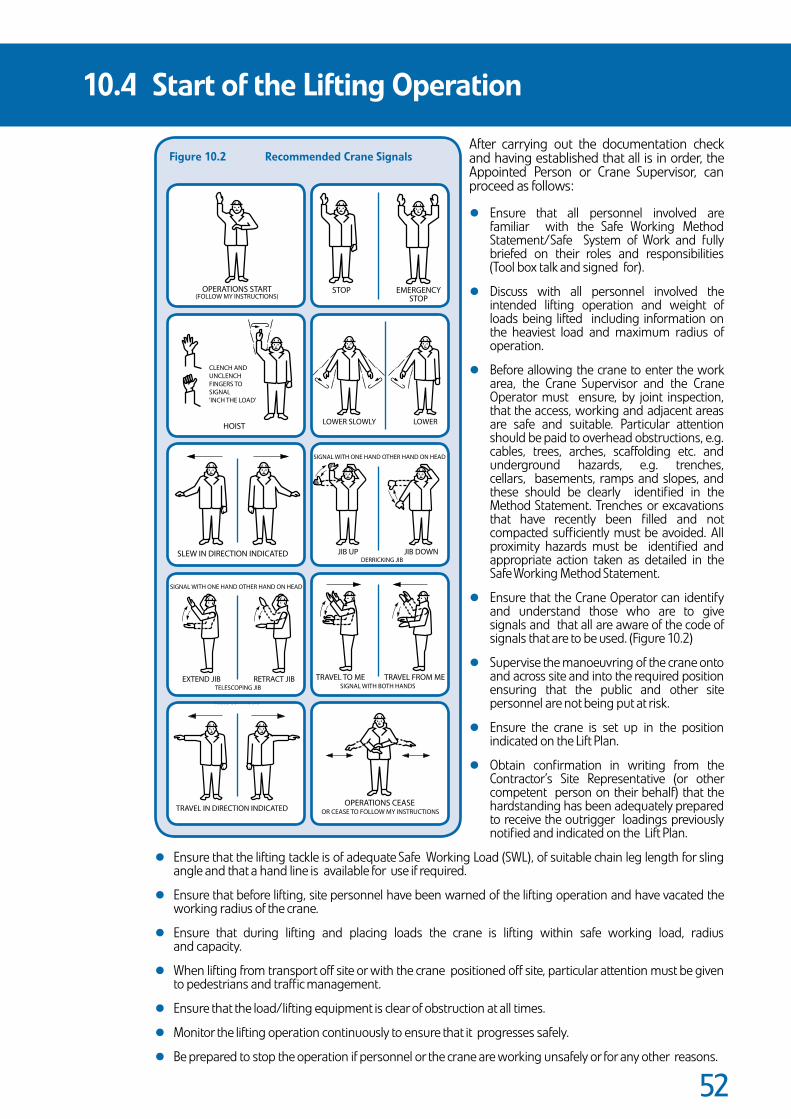
��
After carrying out the documentation check and having established that all is in order, the Appointed Person or Crane Supervisor, can proceed as follows: • Ensure that all personnel involved are familiar with the Safe Working Method Statement/Safe System of Work and fully briefed on their roles and responsibilities (Tool box talk and signed for). • Discuss with all personnel involved the intended lifting operation and weight of loads being lifted including information on the heaviest load and maximum radius of operation. • Before allowing the crane to enter the work area, the Crane Supervisor and the Crane Operator must ensure, by joint inspection, that the access, working and adjacent areas are safe and suitable. Particular attention should be paid to overhead obstructions, e.g. cables, trees, arches, scaffolding etc. and underground hazards, e.g. trenches, cellars, basements, ramps and slopes, and these should be clearly identified in the Method Statement. Trenches or excavations that have recently been filled and not compacted sufficiently must be avoided. All proximity hazards must be identified and appropriate action taken as detailed in the Safe Working Method Statement. • Ensure that the Crane Operator can identify and understand those who are to give signals and that all are aware of the code of signals that are to be used. (Figure 10.2) • Supervise the manoeuvring of the crane onto and across site and into the required position ensuring that the public and other site personnel are not being put at risk. • Ensure the crane is set up in the position indicated on the Lift Plan. • Obtain confirmation in writing from the Contractor’s Site Representative (or other competent person on their behalf) that the hardstanding has been adequately prepared to receive the outrigger loadings previously notified and indicated on the Lift Plan.
• Ensure that the lifting tackle is of adequate Safe Working Load (SWL), of suitable chain leg length for sling angle and that a hand line is available for use if required. • Ensure that before lifting, site personnel have been warned of the lifting operation and have vacated the working radius of the crane. • Ensure that during lifting and placing loads the crane is lifting within safe working load, radius and capacity. • When lifting from transport off site or with the crane positioned off site, particular attention must be given to pedestrians and traffic management. • Ensure that the load/lifting equipment is clear of obstruction at all times. • Monitor the lifting operation continuously to ensure that it progresses safely. • Be prepared to stop the operation if personnel or the crane are working unsafely or for any other reasons.
10.4 StartoftheLiftingOperation
Figure10.2 RecommendedCraneSignals
STOP EMERGENCYSTOP
OPERATIONS START(FOLLOW MY INSTRUCTIONS)
CLENCH ANDUNCLENCHFINGERS TOSIGNAL'INCH THE LOAD'
HOIST LOWERLOWER SLOWLY
SLEW IN DIRECTION INDICATED JIB DOWNDERRICKING JIB
JIB UP
TRAVEL IN DIRECTION INDICATED
SIGNAL WITH ONE HAND OTHER HAND ON HEAD
OPERATIONS CEASEOR CEASE TO FOLLOW MY INSTRUCTIONS
SIGNAL WITH ONE HAND OTHER HAND ON HEAD
EXTEND JIB RETRACT JIBTELESCOPING JIB
TRAVEL TO ME TRAVEL FROM MESIGNAL WITH BOTH HANDS
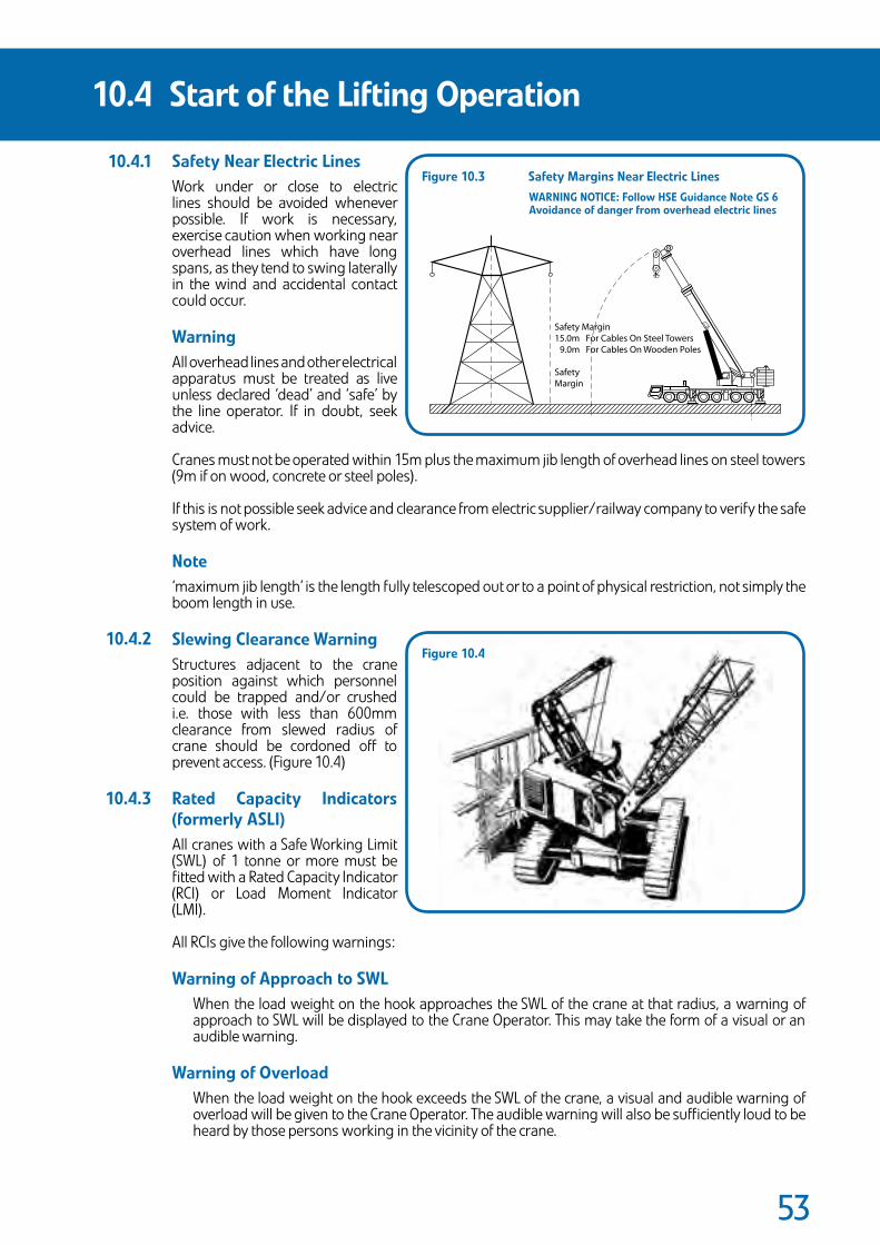
��
SafetyNearElectricLinesWork under or close to electric lines should be avoided whenever possible. If work is necessary, exercise caution when working near overhead lines which have long spans, as they tend to swing laterally in the wind and accidental contact could occur.
WarningAll overhead lines and other electrical apparatus must be treated as live unless declared ‘dead’ and ‘safe’ by the line operator. If in doubt, seek advice.
Cranes must not be operated within 15m plus the maximum jib length of overhead lines on steel towers (9m if on wood, concrete or steel poles).
If this is not possible seek advice and clearance from electric supplier/railway company to verify the safe system of work.
Note‘maximum jib length’ is the length fully telescoped out or to a point of physical restriction, not simply the boom length in use.
SlewingClearanceWarningStructures adjacent to the crane position against which personnel could be trapped and/or crushed i.e. those with less than 600mm clearance from slewed radius of crane should be cordoned off to prevent access. (Figure 10.4)
Rated Capacity Indicators(formerlyASLI)All cranes with a Safe Working Limit (SWL) of 1 tonne or more must be fitted with a Rated Capacity Indicator (RCI) or Load Moment Indicator (LMI).
All RCIs give the following warnings:
WarningofApproachtoSWL When the load weight on the hook approaches the SWL of the crane at that radius, a warning of approach to SWL will be displayed to the Crane Operator. This may take the form of a visual or an audible warning.
WarningofOverload When the load weight on the hook exceeds the SWL of the crane, a visual and audible warning of overload will be given to the Crane Operator. The audible warning will also be sufficiently loud to be heard by those persons working in the vicinity of the crane.
10.4 StartoftheLiftingOperation
Safety Margin15.0m For Cables On Steel Towers
9.0m For Cables On Wooden Poles
SafetyMargin
Figure10.3 SafetyMarginsNearElectricLinesWARNINGNOTICE:FollowHSEGuidanceNoteGS6Avoidanceofdangerfromoverheadelectriclines
Figure10.4
10.4.1
10.4.2
10.4.3
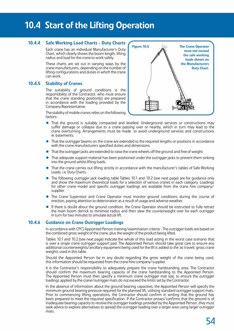
��
SafeWorkingLoadCharts-DutyChartsEach crane has an individual Manufacturer’s Duty Chart, which clearly shows the boom length, lifting radius and load for the crane to work safely. These charts are set out in varying ways by the crane manufacturers, depending on the number of lifting configurations and duties in which the crane can work.
StabilityofCranesThe suitability of ground conditions is the responsibility of the Contractor, who must ensure that the crane standing position(s) are prepared in accordance with the loading provided by the Company Representative. The stability of mobile cranes relies on the following factors:
• That the ground is suitably compacted and levelled. Underground services or constructions may suffer damage or collapse due to a crane passing over or nearby, which in turn may lead to the crane overturning. Arrangements must be made to avoid underground services and constructions ie. basements.
• That the outrigger beams on the crane are extended to the required lengths or positions in accordance with the crane manufacturers specified duties and dimensions.
• That the outrigger jacks are extended to raise the crane wheels off the ground and free of weight.
• That adequate support material has been positioned under the outrigger jacks to prevent them sinking into the ground whilst lifting loads.
• That the crane carries out lifting strictly in accordance with the manufacturer’s tables of Safe Working Loads, i.e. Duty Charts.
• The following outrigger jack loading table Tables 10.1 and 10.2 (see next page) are for guidance only and show the maximum theoretical loads for a selection of various cranes in each category. Loadings for other crane model and specific outrigger loadings are available from the crane hire company/ supplier.
• The Crane Supervisor and Crane Operator must monitor ground conditions during the course of erection, paying attention to deterioration as a result of usage and adverse weather.
• If there is doubt about the ground condition, the Crane Operator should be instructed to fully retract the main boom derrick to minimise radius and then slew the counterweight over for each outrigger in turn for two minutes to simulate actual lift.
GuidanceonCraneOutriggerLoadingsIn accordance with CPCS Appointed Person training/examination criteria - The outrigger loads are based on the combined gross weight of the crane, plus the weight of the product being lifted. Tables 10.1 and 10.2 (see next page) indicate the whole of this load acting in the worst case scenario that is over a single crane outrigger support pad. The Appointed Person should take great care to ensure any additional counterweights/ancillary equipment being used for the lift is added to the ‘as travels’ gross crane weights used in this table. Should the Appointed Person be in any doubt regarding the gross weight of the crane being used, this information should be requested from the crane hire company/supplier. It is the Contractor’s responsibility to adequately prepare the crane hardstanding area. The Contractor should confirm the maximum bearing capacity of the crane hardstanding to the Appointed Person. The Appointed Person must then specify a minimum crane outrigger mat size, to ensure the outrigger loadings applied by the crane/outrigger mats do not exceed the limits set by the Contractor. In the absence of information about the ground bearing capacities, the Appointed Person will specify the minimum ground bearing pressure required for the planned lift, utilising standard outrigger support mats. Prior to commencing lifting operations, the Contractor should confirm in writing that the ground has been prepared to meet the required specification. If the Contractor proves/confirms that the ground is of inadequate bearing capacity to receive the outrigger loadings provided by the Appointed Person, they must seek advice to explore alternatives to spread the outrigger loading over a larger area using larger outrigger mats.
10.4 StartoftheLiftingOperation
Figure10.5 TheCraneOperator mustnotexceed thesafeworking loadsshownon theManufacturers DutyChart.
10.4.4
10.4.5
10.4.6
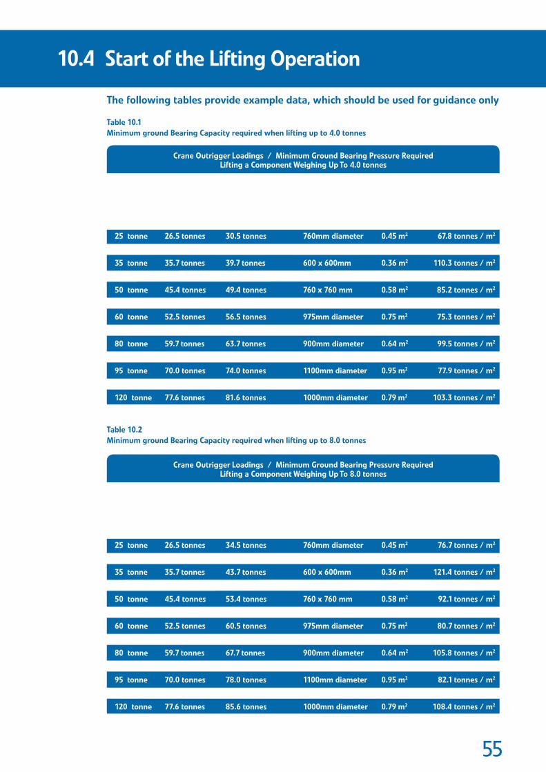
��
Thefollowingtablesprovideexampledata,whichshouldbeusedforguidanceonly
Table10.1MinimumgroundBearingCapacityrequiredwhenliftingupto4.0tonnes
Table10.2MinimumgroundBearingCapacityrequiredwhenliftingupto8.0tonnes
10.4 StartoftheLiftingOperation
25tonne
30tonne
35tonne
40tonne
50tonne
55tonne
60tonne
70tonne
80tonne
90tonne
95tonne
100tonne
120tonne
CraneCapacity
26.5tonnes
27.7tonnes
35.7tonnes
39.5tonnes
45.4tonnes
43.0tonnes
52.5tonnes
55.8tonnes
59.7tonnes
61.0tonnes
70.0tonnes
75.9tonnes
77.6tonnes
TypicalGrossWeightOfCrane
30.5tonnes
31.7tonnes
39.7tonnes
43.5tonnes
49.4tonnes
47.0tonnes
56.5tonnes
59.8tonnes
63.7tonnes
65.0tonnes
74.0tonnes
79.9tonnes
81.6tonnes
CraneOutriggerLoadings/MinimumGroundBearingPressureRequiredLiftingaComponentWeighingUpTo4.0tonnes
GrossWeightOfCrane+4.0tonnesLift=MaximumPotentialOutriggerLoad/Pad
760mmdiameter
760mmdiameter
600x600mm
760mmdiameter
760x760mm
900mmdiameter
975mmdiameter
900mmdiameter
900mmdiameter
900mmdiameter
1100mmdiameter
1000mmdiameter
1000mmdiameter
Typical/’Standard’OutriggerPadSize
0.45m2
0.45m2
0.36m2
0.45m2
0.58m2
0.64m2
0.75m2
0.64m2
0.64m2
0.64m2
0.95m2
0.79m2
0.79m2
Typical/‘Standard’OutriggerPadArea
67.8tonnes/m2
70.4tonnes/m2
110.3tonnes/m2
96.7tonnes/m2
85.2tonnes/m2
73.4tonnes/m2
75.3tonnes/m2
93.4tonnes/m2
99.5tonnes/m2
101.6tonnes/m2
77.9tonnes/m2
101.1tonnes/m2
103.3tonnes/m2
MinimumGroundBearing
PressureRequired
25tonne
30tonne
35tonne
40tonne
50tonne
55tonne
60tonne
70tonne
80tonne
90tonne
95tonne
100tonne
120tonne
CraneCapacity
26.5tonnes
27.7tonnes
35.7tonnes
39.5tonnes
45.4tonnes
43.0tonnes
52.5tonnes
55.8tonnes
59.7tonnes
61.0tonnes
70.0tonnes
75.9tonnes
77.6tonnes
TypicalGrossWeightOfCrane
34.5tonnes
35.7tonnes
43.7tonnes
47.5tonnes
53.4tonnes
51.0tonnes
60.5tonnes
63.8tonnes
67.7tonnes
69.0tonnes
78.0tonnes
83.9tonnes
85.6tonnes
CraneOutriggerLoadings/MinimumGroundBearingPressureRequiredLiftingaComponentWeighingUpTo8.0tonnes
GrossWeightOfCrane+8.0tonnesLift=MaximumPotentialOutriggerLoad/Pad
760mmdiameter
760mmdiameter
600x600mm
760mmdiameter
760x760mm
900mmdiameter
975mmdiameter
900mmdiameter
900mmdiameter
900mmdiameter
1100mmdiameter
1000mmdiameter
1000mmdiameter
Typical/’Standard’OutriggerPadSize
0.45m2
0.45m2
0.36m2
0.45m2
0.58m2
0.64m2
0.75m2
0.64m2
0.64m2
0.64m2
0.95m2
0.79m2
0.79m2
Typical/‘Standard’OutriggerPadArea
76.7tonnes/m2
79.3tonnes/m2
121.4tonnes/m2
105.6tonnes/m2
92.1tonnes/m2
79.7tonnes/m2
80.7tonnes/m2
99.7tonnes/m2
105.8tonnes/m2
107.8tonnes/m2
82.1tonnes/m2
106.2tonnes/m2
108.4tonnes/m2
MinimumGroundBearing
PressureRequired

��
Examplecalculations[basedona50tonnecrane,lifting4.0tonnes]
1. Where a definitive ground bearing pressure is provided by the Contractor inadvance:
• Ground bearing capacity confirmed following engineer’s ground testing is 28.5 tonnes / m2.
• Maximum potential outrigger load/pad (from Table 10.1) is 49.4 tonnes.
• Minimum crane mat size required is 49.4 ÷ 28.5 = 1.733m2.
• Standard 50 tonne crane mats = 0.58m2 therefore inadequate.
• Larger crane mats required to ensure crane stability, with a minimum area of 1.733 m2 per crane outrigger.
2. WhereadefinitivegroundbearingpressureisnotprovidedbytheContractor:
• Maximum potential outrigger load/pad (from Table 10.1) is 49.4 tonnes.
• Utilising standard crane mats of 0.58m2.
• Minimum ground bearing pressure required is 49.4 ÷ 0.58 = 85.2 tonnes / m2.
• Contractor to confirm in writing (prior to commencement of lifting operations) that the ground has been adequately prepared to withstand this maximum outrigger loading.
Note
Ground loadbearing test results for a given area can vary from day to day, as ground moisture content is a major factor in determining its loadbearing characteristics. It is prudent to apply a factor of safety to all calculations where there is any possibility of ground deterioration after tests have been undertaken.
10.4 StartoftheLiftingOperation
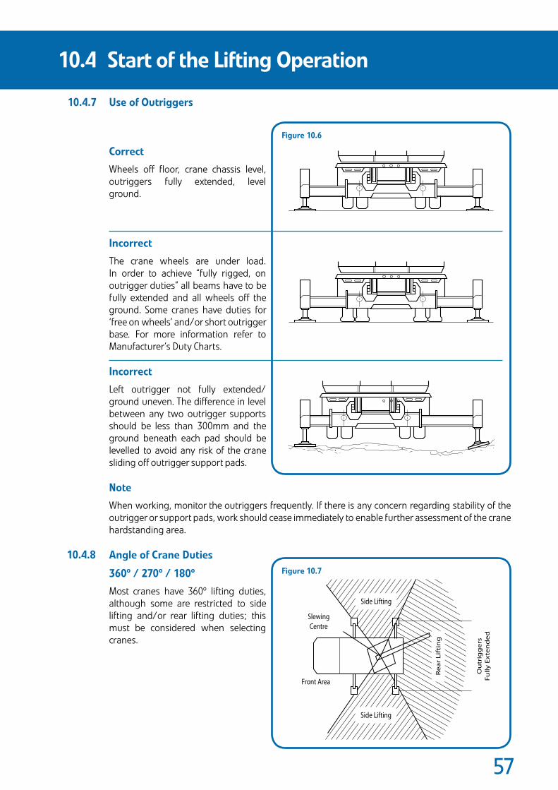
��
UseofOutriggers
Correct
Wheels off floor, crane chassis level, outriggers fully extended, level ground.
Incorrect
The crane wheels are under load. In order to achieve “fully rigged, on outrigger duties” all beams have to be fully extended and all wheels off the ground. Some cranes have duties for ‘free on wheels’ and/or short outrigger base. For more information refer to Manufacturer’s Duty Charts.
Incorrect
Left outrigger not fully extended/ground uneven. The difference in level between any two outrigger supports should be less than 300mm and the ground beneath each pad should be levelled to avoid any risk of the crane sliding off outrigger support pads.
Note
When working, monitor the outriggers frequently. If there is any concern regarding stability of the outrigger or support pads, work should cease immediately to enable further assessment of the crane hardstanding area.
AngleofCraneDuties
360º/270º/180º
Most cranes have 360º lifting duties, although some are restricted to side lifting and/or rear lifting duties; this must be considered when selecting cranes.
10.4 StartoftheLiftingOperation
SlewingCentre
Front Area
Ou
trig
ge
rsF
ull
yE
xte
nd
ed
Side Lifting
Side Lifting
Re
ar
Lif
tin
g
Figure10.7
Figure10.6
10.4.7
10.4.8
��
The Contractor is responsible for ensuring that the tower crane has been erected and maintained by a competent person, in accordance with BS 7121 - Part 5 and the crane manufacturer’s recommendations.
The Contractor is also responsible for ensuring that the lifting operation carried out by the tower crane is properly planned by a competent person in accordance with BS 7121 - Part 5. The person planning the lifting operation should have sufficient knowledge and experience of such operations. The plan must address risks identified during risk assessment and must show the resources required, in addition to procedures and responsibilities, so that the lifting operation can be carried out safely. The plan must also ensure that the lifting equipment remains safe for the different lifting operations/load configurations for which it will be used.
The Contractor is responsible for ensuring that the tower crane is capable of the duties required for lifting and installing the precast concrete units.
The Company is responsible for ensuring that the Contractor is provided with the weights and positions of the precast concrete units to allow the Contractor to fulfil his duties and adequately plan the lifting operation.
The Contractor must provide the Company with details of dedicated offloading points for delivery vehicles.
As with other cranes, the tower cranes must be properly tested and certificated. They must be operated by trained certificated persons, unless under the direct supervision of a certificated person for the purpose of training. The only other persons who should be allowed access to a tower crane are those people authorised by the Crane Owner/hirer, in order that they can carry out their legitimate business e.g. maintenance workers, inspectors. This should only be done only after work is suspendedand the area is cordoned off.
The Contractor should give special consideration when two or more cranes are being operated in close proximity, to avoid jibs coming into contact with other crane equipment e.g. lifting ropes.
Any equipment used on site must be fully certified and used only by trained and competent personnel.
10.5 TowerCranes
10.6 UseofOnSiteEquipment
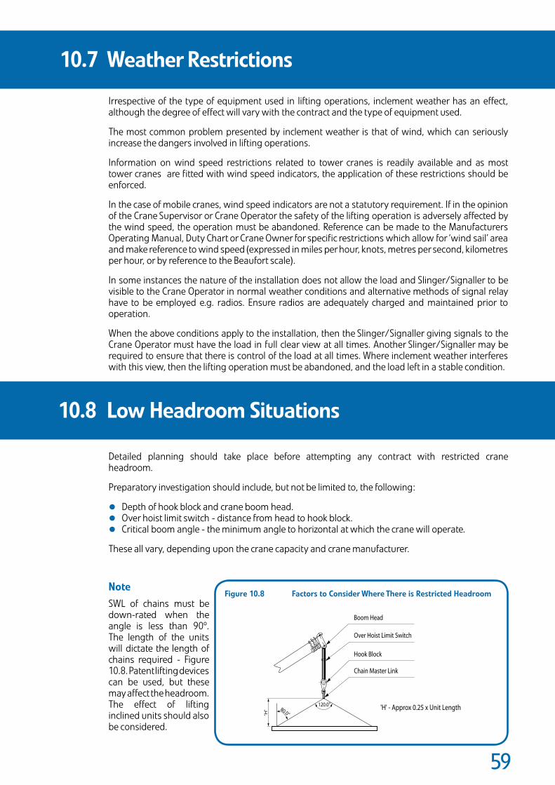
��
Irrespective of the type of equipment used in lifting operations, inclement weather has an effect, although the degree of effect will vary with the contract and the type of equipment used.
The most common problem presented by inclement weather is that of wind, which can seriously increase the dangers involved in lifting operations.
Information on wind speed restrictions related to tower cranes is readily available and as most tower cranes are fitted with wind speed indicators, the application of these restrictions should be enforced.
In the case of mobile cranes, wind speed indicators are not a statutory requirement. If in the opinion of the Crane Supervisor or Crane Operator the safety of the lifting operation is adversely affected by the wind speed, the operation must be abandoned. Reference can be made to the Manufacturers Operating Manual, Duty Chart or Crane Owner for specific restrictions which allow for ‘wind sail’ area and make reference to wind speed (expressed in miles per hour, knots, metres per second, kilometres per hour, or by reference to the Beaufort scale).
In some instances the nature of the installation does not allow the load and Slinger/Signaller to be visible to the Crane Operator in normal weather conditions and alternative methods of signal relay have to be employed e.g. radios. Ensure radios are adequately charged and maintained prior to operation.
When the above conditions apply to the installation, then the Slinger/Signaller giving signals to the Crane Operator must have the load in full clear view at all times. Another Slinger/Signaller may be required to ensure that there is control of the load at all times. Where inclement weather interferes with this view, then the lifting operation must be abandoned, and the load left in a stable condition.
Detailed planning should take place before attempting any contract with restricted crane headroom.
Preparatory investigation should include, but not be limited to, the following:
• Depth of hook block and crane boom head.
• Over hoist limit switch - distance from head to hook block.
• Critical boom angle - the minimum angle to horizontal at which the crane will operate.
These all vary, depending upon the crane capacity and crane manufacturer.
NoteSWL of chains must be down-rated when the angle is less than 90º. The length of the units will dictate the length of chains required - Figure 10.8. Patent lifting devices can be used, but these may affect the headroom. The effect of lifting inclined units should also be considered.
10.7 WeatherRestrictions
10.8 LowHeadroomSituations
Boom Head
Over Hoist Limit Switch
Hook Block
Chain Master Link
'H' - Approx 0.25 x Unit Length120.0°80.0°'H
'
Figure10.8 FactorstoConsiderWhereThereisRestrictedHeadroom
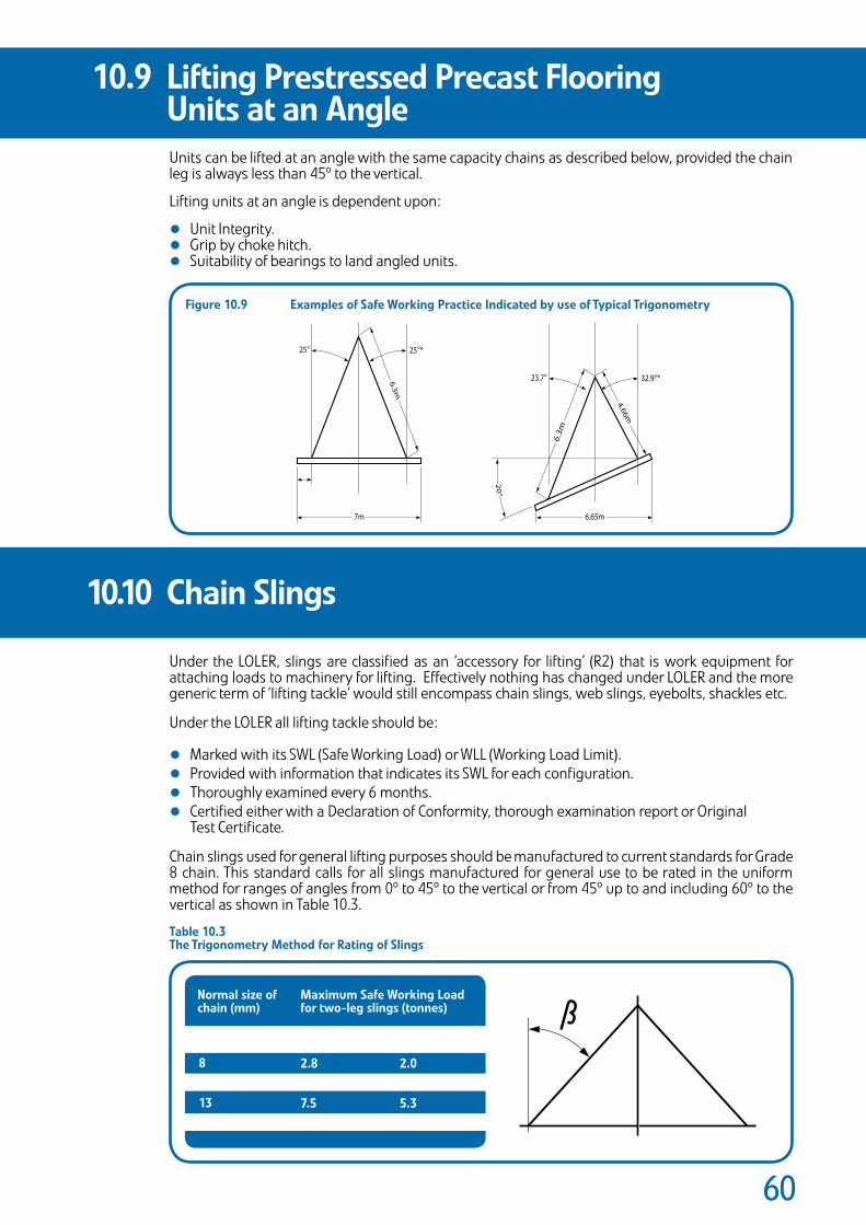
�0
Units can be lifted at an angle with the same capacity chains as described below, provided the chain leg is always less than 45º to the vertical.
Lifting units at an angle is dependent upon:
• Unit Integrity.• Grip by choke hitch.• Suitability of bearings to land angled units.
Under the LOLER, slings are classified as an ‘accessory for lifting’ (R2) that is work equipment for attaching loads to machinery for lifting. Effectively nothing has changed under LOLER and the more generic term of ‘lifting tackle’ would still encompass chain slings, web slings, eyebolts, shackles etc.
Under the LOLER all lifting tackle should be:
• Marked with its SWL (Safe Working Load) or WLL (Working Load Limit).
• Provided with information that indicates its SWL for each configuration.
• Thoroughly examined every 6 months.
• Certified either with a Declaration of Conformity, thorough examination report or Original Test Certificate.
Chain slings used for general lifting purposes should be manufactured to current standards for Grade 8 chain. This standard calls for all slings manufactured for general use to be rated in the uniform method for ranges of angles from 0º to 45º to the vertical or from 45º up to and including 60º to the vertical as shown in Table 10.3.
Table10.3TheTrigonometryMethodforRatingofSlings
10.9 LiftingPrestressedPrecastFlooring UnitsatanAngle
10.10 ChainSlings
7m
6.3m
25° 25°*
6.65m
23.7° 32.9°*
4.66m
6.3
m
20°
Figure10.9 ExamplesofSafeWorkingPracticeIndicatedbyuseofTypicalTrigonometry
Normalsizeofchain(mm)
MaximumSafeWorkingLoadfortwo-legslings(tonnes)
2.84.257.511.2
2.03.155.38.0
8101316
0º<45º 45º<60º
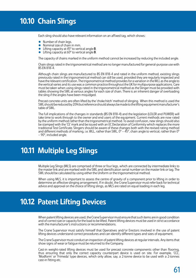
�1
Each sling should also have relevant information on an affixed tag, which shows:
• Number of chain legs.• Nominal size of chain in mm.• Lifting capacity at 45º to vertical angle ß.• Lifting capacity at 60º to vertical angle ß.
The capacity of chains marked in the uniform method cannot be increased by reducing the included angle.
Chain slings rated in the trigonometrical method are no longer manufactured for general-purpose use with BS EN 818-4.
Although chain slings are manufactured to BS EN 818-4 and rated in the uniform method, existing slings previously rated in the trigonometrical method can still be used, provided they are regularly inspected and have the relevant certification. The trigonometrical method provides for a variation in the WLL as the angle to the vertical varies and its use was a common practice throughout the UK for multipurpose applications. Care must be taken when using slings rated in the trigonometrical method as the Slinger must be provided with tables showing the SWL at various angles for each size of chain. There is an inherent danger of overloading the sling if the angles have been misjudged.
Precast concrete units are often lifted by the ‘choke hitch’ method of slinging. When this method is used the SWL should be reduced by 20% but reference should always be made to the lifting equipment manufacturer’s table of SWL.
The full implications of the changes in standards (BS EN 818-4) and the legislation (LOLER and PUWER) will take time to work through to the owner and end users of the equipment. Current methods are now rated by the uniform method rather than the trigonometrical method. To avoid confusion, new slings should also be stamped with the ‘CE’ mark and be issued with an EC Declaration of Conformity which replaces the more traditional Test Certificate. Slingers should be aware of these changes both with the revised rating method and different methods of marking, i.e. WLL, rather than SWL, 0º – 45º, chain angle to vertical, rather than 0º – 90º, included angle.
Multiple Leg Slings (MLS) are comprised of three or four legs, which are connected by intermediate links to the master link and are marked with the SWL and identification serial number on the master link or tag. The SWL should be calculated by using either the Uniform or the trigonometrical method.
When using MLS, it is important to assess the centre of gravity of a component prior to lifting in order to determine an effective slinging arrangement. If in doubt, the Crane Supervisor must refer back for technical advice and approval on the choice of lifting slings, as MLS are rated on equal loading in each leg.
When patent lifting devices are used, the Crane Supervisor must ensure that such items are in good condition and of correct size or capacity for the load to be lifted. Patent lifting devices must be used in strict accordance with the manufacturer’s instructions or recommendations.
The Crane Supervisor must satisfy himself that Operatives and/or Erectors involved in the use of patent lifting devices understand correct procedures and can identify different types and sizes of equipment.
The Crane Supervisor must conduct an inspection of patent lifting devices at regular intervals. Any items that show signs of wear or fatigue must be returned to the Company.
Cast-in weight-rated lifting devices must be used for precast concrete components other than flooring, thus ensuring that only the correct capacity counterpart device is used on site. For example, ‘CCL’, ‘Modform’ or ‘Frimeda’ type devices, which only allow, say, a 2-tonne device to be used with a 2-tonnes cast-in fitting etc.
10.12 PatentLiftingDevices
10.11 MultipleLegSlings
10.10 ChainSlings
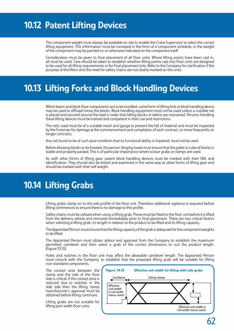
��
The component weight must always be available on site to enable the Crane Supervisor to select the correct lifting equipment. This information must be conveyed in the form of a component schedule, or the weight of the component may be painted on or otherwise indicated on the component itself.
Consideration must be given to final placement of all floor units. Where lifting points have been cast in, all must be used. Care should be taken to establish whether lifting points cast into floor units are designed to be used for all lifting requirements or for final placement only. Refer to the Company for clarification if the purpose of the lifters and the need for safety chains are not clearly marked on the units.
When beam and block floor components are to be installed, some form of lifting fork or block handling device may be used to offload/move the blocks. Block handling equipment must not be used unless a suitable net is placed and secured around the load in order that falling blocks or debris are restrained. Persons handling these lifting devices must be trained and competent in their use and restrictions.
The nets used must be of a suitable mesh and gauge to prevent the fall of material and must be inspected by the Foreman for damage at the commencement and completion of each contract, or more frequently on longer contracts.
Any net found to be of such poor condition that its functional ability is impaired, must not be used.
Before allowing blocks to be hoisted, the person slinging loads must ensure that the pallet or cube of blocks is stable and properly packed. This is of particular importance where scissor grabs or clamps are used.
As with other forms of lifting gear, patent block handling devices must be marked with their SWL and identification. They should also be tested and examined in the same way as other forms of lifting gear and should be marked with their self weight.
Lifting grabs clamp on to the side profile of the floor unit. Therefore additional vigilance is required before lifting commences to ensure there is no damage to this profile.
Safety chains must be utilised when using a lifting grab. These must be fitted to the floor unit before it is lifted from the delivery vehicle and removed immediately prior to final placement. There are two critical factors when selecting a lifting grab; its length in relation to the product to be lifted and its lifting capacity.
The Appointed Person must ensure that the lifting capacity of the grab is adequate for the component weights to be lifted.
The Appointed Person must obtain advice and approval from the Company to establish the maximum permitted cantilever and then select a grab of the correct dimensions to suit the product length. (Figure.10.10)
Holes and notches in the floor unit may affect the allowable cantilever length. The Appointed Person must consult with the Company, to establish that the proposed lifting grab will be suitable for lifting non-standard components.
The contact area between the clamp and the side of the floor slab is critical. If the contact area is reduced due to notches in the slab side then the lifting clamp manufacturer’s approval must be obtained before lifting continues.
Lifting grabs are not suitable for lifting part-width floor units.
10.14 LiftingGrabs
10.13 LiftingForksandBlockHandlingDevices
10.12 PatentLiftingDevices
Figure10.10 Effectiveunitwidthforliftingwithsidegrabs
L�ft�ng clampCant�lever
Effect�ve un�t w�dth �s full w�dth m�nus notch
Effect�ve un�t w�dth �s full w�dth m�nus notch
Section 11:Movement of Units by Other Means
Precast Flooring Federation
Sect
ion
11
Dividers.indd 11 9/6/08 15:52:45
��
Components should be positioned as near as possible to their final position to minimise barring, however, the use of pinch or crow bars to move components is common to all types of floor unit and all categories of contract. The bar is used to move individual units into their final position, and to tighten up a floor after laying.
In whatever situation barring is carried out, there are basic precautions that must be observed:
• The ability of the structure to withstand this type of movement must be considered at the design stage and the Erectors must satisfy themselves as to the robustness of the bearings before carrying out this operation and seek professional advice if unsure. If barring cannot be avoided and the bearings are not considered robust enough then the units must not be positioned until the bearing is improved, or some temporary measures taken such as properly designed temporary support to the components or bracing of the bearings.
• The bar itself must be of sound construction and of adequate strength. It should be long enough to enable the person barring the component to stand upright.
• The end of the bar should be shaped such that it can gain maximum purchase onto the unit to be moved. The heel of the bar must be able to fully bear onto the units or structure being barred against.
• Where a possibility of damage to other surfaces exists, protective measures should be employed to prevent spalling or fracture.
• Components should not be moved by this method unless there are sufficient units or other elements of structure to provide a suitable platform on which the person(s) carrying out the operation can stand. Such a platform must be of sufficient size to enable the person(s) to properly brace himself and to ensure that in the event of bar slippage, the person will not fall through a void, or over an edge. Section 13.4.1 of this Code of Practice deals with the question of edge protection. When moving components by this means, care must be taken to ensure that the units are not damaged to an extent that will impair their structural integrity.
• Components must be positioned or moved by a succession of small movements. No attempt should be made to slide or lift units for distances that would cause the person(s) involved in the operation to lose their balance, or to hold excessive weight on a bar.
11.1 Barring
��
The use of jacks to raise precast units is not common and should be avoided wherever possible. In instances where there may be particular requirements to use jacking it should only be implemented after a full risk/design assessment has been undertaken. These jacking works should be short-term, for the purpose of removing chocks or chains and should not be used for temporary support. The points below should be considered:
• Whenever jacks are used, they must be of adequate strength and capacity to safely raise and hold the load. Steel or hardwood wedges should be used to provide an additional safeguard when a component is required to remain raised for some time and whenever practicable, adjustable steel props should be used. When jacking up a component, the Foreman must ensure that the jack is sited on a firm level base. If jacking from a floor, the Foreman must ensure by reference to the Company that the floor is capable of safely supporting the jack and the weight of any load being raised.
• Care must be taken to ensure that the operation does not make the bearings unstable by introducing additional load or lateral forces to one end or leave the component in an unstable condition such that it could move whilst supported on the jack(s).
• No person should be allowed access to the area above whilst jacking is taking place and only essential personnel will be allowed in the working area below.
• Jacks are often used in conjunction with adjustable steel props to raise components to a required level. In such circumstances, the Foreman must ensure that the adjustable prop is held vertically and will adequately carry the load. Components must only be raised a few millimetres by this means; greater lifts or movement must be undertaken by lifting appliances.
In all cases, jacks must be used in compliance with the instructions and recommendations of the manufacturer. The Foreman should conduct regular visual examinations of jacking equipment. Any defective items must not be used.
Where, for practical reasons, cranes may not be employed, other methods may be devised and used subject to a full design and installation risk assessment in agreement between the Contractor and the Company. Whenever possible such situations should be designed out.
11.2 Jacking
11.3 OtherMeansofInstalling orMovingComponents

Section 12:Additional On Site Works
Precast Flooring Federation
Sect
ion
12
Dividers.indd 12 9/6/08 15:52:45

��
The practice of erecting precast units onto temporary bearings must be avoided wherever possible. In cases where such measures are unavoidable, the requirement to fix on temporary bearings must be notified to the Company at the design stage of the contract, and fixing must not progress until written confirmation has been obtained by the Contractor’s Site Representative, from a competent technical authority, that the temporary structure has been suitably designed.
Should propping be required as bearing enhancement during the construction phase, this will be indicated on the construction drawings and/or Safe Working Method Statement. Props should be designed and installed by competent persons employed by the Contractor.
Wet concrete, mould oil and timber treatments are skin irritants and the requirements of the COSHH Assessment and the Personal Protective Equipment at Work Regulations 1989 must be complied with.
Insitu concrete work must be executed in accordance with Working Drawings, Risk Assessments and Safe Working Method Statement.
No insitu works should be carried out without reference to the Company so that any design implications can be assessed and the work recorded.
Insitu concrete can be supported either on permanent shutters, or on formwork. In the case of permanent shutters, these should be tight fitting to one another and their size should be such that the total area of concrete is supported. Permanent shutter units must be examined for cracking or other damage before any wet concrete is placed on them. These may need propping until the concrete is adequately cured. Where props are used, these must be designed by a competent person with due regard to number and position, and installed as directed by the Building Designer.
When formwork is used, this must be of sufficient strength to support its own weight, and that of the concrete, together with reinforcement and the weight of any Operatives or plant engaged in the work. Formwork and steel reinforcement must be designed, constructed and erected by competent persons and should be closely examined before, during and after the placing of concrete, in accordance with the requirements of current Standards and Codes.
The Contractor must ensure that adequate scaffold for safe access to the work place is made available.
When using a mobile poker, care must be taken that the power unit is stood on a firm, level base and operated in accordance with the manufacturer’s instructions.
Before commencing any insitu concrete placement, the Foreman should ensure that the weather conditions are satisfactory so far as could be reasonably foreseen (as shown in Figure 12.1). Concreting should not commence in conditions likely to cause its failure or displacement, unless adequate measures are implemented to protect it. In all cases where work is not commenced, or doubt exists as to the suitability of weather conditions, the Company’s Representative must advise the Company of the situation.
Whilst insitu work is in progress, the Foreman and site management team should ensure that the areabeneath the work being completed is kept clear of all personnel not engaged in this work.
12.1 TemporaryStructuralSupport
12.2 Proping
12.3 InsituConcrete
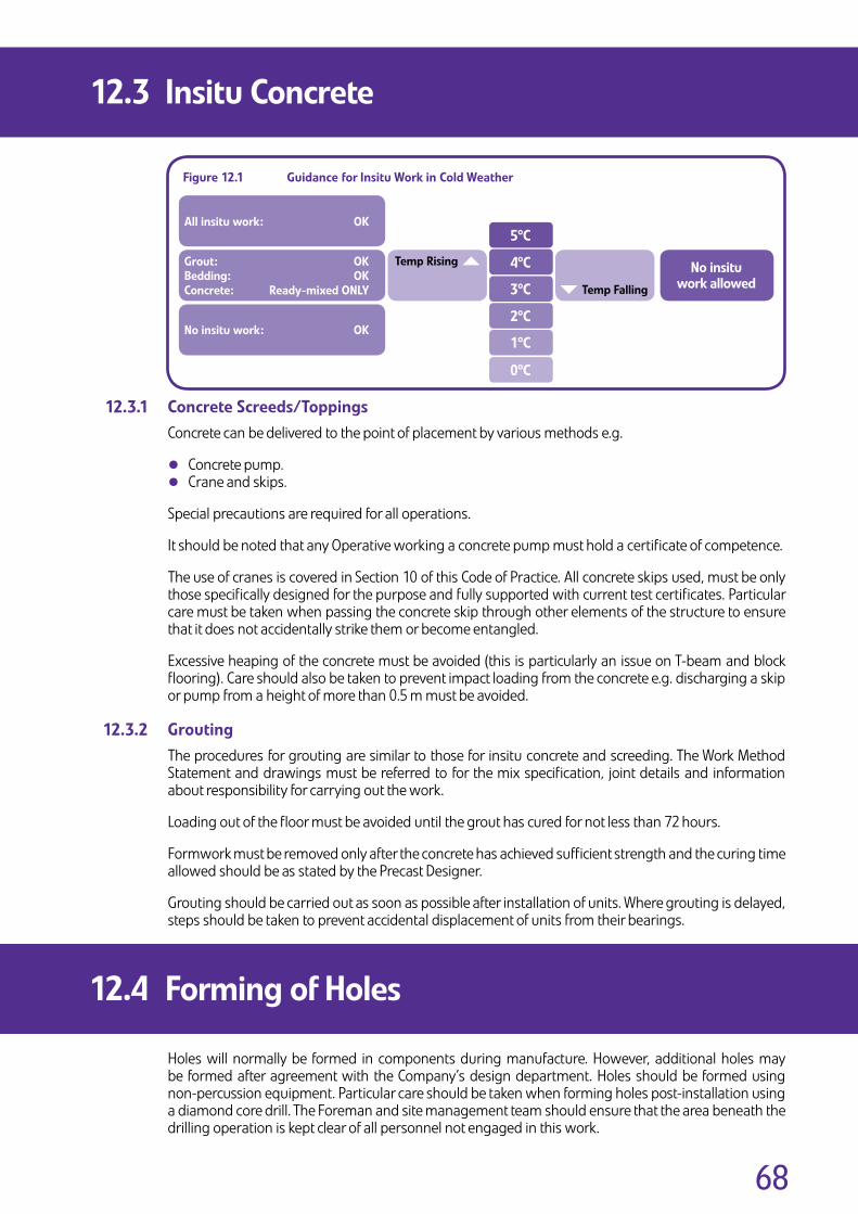
��
ConcreteScreeds/ToppingsConcrete can be delivered to the point of placement by various methods e.g.
• Concrete pump.
• Crane and skips.
Special precautions are required for all operations.
It should be noted that any Operative working a concrete pump must hold a certificate of competence.
The use of cranes is covered in Section 10 of this Code of Practice. All concrete skips used, must be only those specifically designed for the purpose and fully supported with current test certificates. Particular care must be taken when passing the concrete skip through other elements of the structure to ensure that it does not accidentally strike them or become entangled.
Excessive heaping of the concrete must be avoided (this is particularly an issue on T-beam and block flooring). Care should also be taken to prevent impact loading from the concrete e.g. discharging a skip or pump from a height of more than 0.5 m must be avoided.
GroutingThe procedures for grouting are similar to those for insitu concrete and screeding. The Work Method Statement and drawings must be referred to for the mix specification, joint details and information about responsibility for carrying out the work.
Loading out of the floor must be avoided until the grout has cured for not less than 72 hours.
Formwork must be removed only after the concrete has achieved sufficient strength and the curing time allowed should be as stated by the Precast Designer.
Grouting should be carried out as soon as possible after installation of units. Where grouting is delayed, steps should be taken to prevent accidental displacement of units from their bearings.
Holes will normally be formed in components during manufacture. However, additional holes may be formed after agreement with the Company’s design department. Holes should be formed using non-percussion equipment. Particular care should be taken when forming holes post-installation using a diamond core drill. The Foreman and site management team should ensure that the area beneath the drilling operation is kept clear of all personnel not engaged in this work.
12.3 InsituConcrete
12.4 FormingofHoles
Figure12.1 GuidanceforInsituWorkinColdWeather
Grout: OKBedding: OKConcrete: Ready-mixedONLY
Allinsituwork: OK
Noinsituwork: OK
5ºC
4ºC
3ºC
2ºC
1ºC
0ºC
TempRising
TempFalling
Noinsituworkallowed
12.3.1
12.3.2

Section 13:Access to Working Area, Work at Height and Protection Against Falls
Precast Flooring Federation
Sect
ion
13
Dividers.indd 13 9/6/08 15:52:45

�0
The Work at Height Regulations 2005 (as amended), gives employers the following hierarchy to follow when planning work at height:
The following is taken from HSE Document: HSG 150:
Those in control of work must:
• Avoid work at height where they can.
• Use work equipment to prevent falls where work at height cannot be avoided.
• Where the risk of a fall cannot be eliminated, use work equipment to minimise the distance and consequences of a fall should one occur.
• Always consider measures that protect all those at risk i.e. collective protection measures (scaffolds, nets, soft landing systems) before measures that only protect the individual i.e. personal protection measures (a harness).
• Ensure work is carried out only when weather conditions do not jeopardise the health and safety of the workers.
Generally the installation of precast flooring and stairs etc. will require the Operatives to work at height. This work will require careful planning following the hierarchy of controls to reduce the risks of working at height.
There are a range of measures available to protect the perimeter of the building/working area and theleading edge e.g. working platforms, handrails, work restraint, safety nets, air bags and fall arrest. All of these should be considered within the hierarchy of measures and selection will be dependent upon the type of floor being installed and the structure the floor is being installed onto. The system that affords the most reasonably practicable level of protection should be employed.
13.1 Introduction
13.2 GeneralPrinciplesforControlMeasures
Figure13.1 TheWorkatHeightHierarchy
Avo�d work at he�ght where they can
Use work equ�pment or other measures to prevent falls where they
cannot avo�d work�ng at he�ght;
Where they cannot el�m�nate the r�sk of a fall, use work equ�pment or other measures to m�n�m�se the d�stance and consequences of a fall should one occur.
DUTYHOLDERSMUST:

�1
Safe means of access to the working area also requires careful planning, particularly where work progresses during installation. Safe means of access should be agreed with the Company Representative and positioned adjacent to the start point, where reasonably practicable.
Typical methods include:
• Independent scaffolds.
• Suitably protected stairs and ramps.
• Fixed or mobile scaffold towers.
• Mobile access equipment.
• Secured ladders.
More detailed advice on the selection and use of access equipment is given in HSE guidance listed below:
• CIS No 10 Tower Scaffolds (rev. 4).
• HSE Information Sheet MISC 614 Preventing Falls From Boom Type Mobile Elevating Work Platforms.
• HSG 150 Health and Safety in Construction (pages 14 to 37).
The hierarchy to be used has been outlined in Sections 13.1 and 13.2.
In practice, the perimeter of the building should be protected by the Contractor, by means of scaffold/guardrails/working platforms which prevent a fall.
The leading edge should be protected using the following hierarchy:
Note
All systems mentioned must comply with appropriate schedules given in the Work at Height Regulations 2005.
13.3 SafeAccesstotheWorkingArea
13.4 WorkingatHeight–ControlMeasures
Th�s system prevents a fall. However, �t l�m�ts access to the lead�ng edge and rel�es on the Operat�ve to act and �s therefore act�ve and personal. In the precast floor�ng �ndustry exper�ence has shown that pass�ve and collect�ve systems are far more effect�ve �n prevent�ng �njury and thus preferred (see sect�on 1�.�.�.� Work Restra�nt Systems).
Systems that do not rely on the �nstaller to operate them and are �n place pr�or to the first un�t be�ng �nstalled. Pass�ve and collect�ve systems �nclude nets, a�r bags, deck�ng and many other systems. They m�n�m�se the d�stance and consequence of a fall should one occur. Systems for fall arrest rely on the Erector to use them and are also act�ve and personal. They systems requ�re the calculat�on of the max�mum drop an erector could suffer as a worst case to ensure that the floor-to-floor he�ght �s suffic�ent to prevent the fallen person com�ng �nto contact w�th the floor. Rescue of the fallen person must also be cons�dered when des�gn�ng such a system.
Act�ve WorkRestra�nt Systems
Pass�ve andCollect�ve Systems
Act�ve FallArrest Systems

��
ScaffoldandEdgeProtectionA scaffold with the required handrails must be in position prior to units being installed to provide safe access to bearing level and access around the edge of the installation area. The Contractor and the Company Representative should agree exactly what is necessary and what will be provided by the Contractor. The Contractor should ensure that all scaffolds are erected by a competent person, are suitable and safe prior to work commencing, and comply with the appropriate schedule in the Work at Height Regulations 2005 i.e. the handrail has a minimum height of 950mm, the gap between rails is a maximum gap of 470mm and there is suitable protection against falling materials.
All scaffolds need to be constructed so as not to adversely affect the installation operation or the operation of the crane. The following recommendations are made for the different circumstances where scaffold edge protection systems could be used:
MasonryConstruction (Figures 13.2 and 13.3)Where a scaffold is constructed to allow access to a masonry bearing the scaffold should be positioned no more than 900mm below the top of the floor unit and the platform should be of adequate width (no less than 600mm).
Scaffold standards must not extend above the upper handrail to a position where they will interfere with the operation of the crane or the installation of the precast flooring.
Access to the working platform must be restricted or prevented unless an additional inner guardrail is in place or the passive fall arrest is deployed.
Steel Frame (Figure 13.4) On steel frame buildings handrails are required to the external face of the building. They should be installed to the outside of the steel frame so as not to interfere with the installation of the flooring.
Additional guardrails may be required to ensure that the gap is no greater than 470mm. Lowest guardrail to be set at 470mm from top of steel.
13.4 WorkingatHeight–ControlMeasures
Min 600
Max
900
Do
wn
Min
950
Max
470
Figure13.2 MasonryConstruction
Additional innerhandrail
Figure13.3 MasonryConstruction
Min
950
470
Additional rails may be required if the distance fromthe top of the floor to the top rail is below 950mm
The maximumdistance betweenall gaps must be nomore than 470mm
Figure13.4 SteelFrame
N.B. This platform is suitable for the installation of flooring beams.
Where following trade require to use the scaffold, the scaffold may need further modification.
Scaffold no more than900mm below top of slab.
N.B. This platformis suitable for a safe access path to full working perimeter prior to passive fall protection being in place.
13.4.1

��
LeadingEdgeControlMeasures
WorkingPlatforms(e.g.decking,birdcage)Where provided, working platforms should fully cover the internal area under the floor installation.
Several options are available to achieve a working platform, including enhanced lightweight decking systems and scaffolding.
When scaffold systems are used care should be taken to ensure that scaffold poles do not extend above the level of the deck, where they could cause injury to a falling person or cause a trip hazard.
When lightweight decking systems are used, care should be taken to ensure that the system is designed/erected as a working platform and that the surrounding structure affords adequate lateral restraint where required. Some systems require enhancement over and above the standard ‘crash deck only’ assembly configuration. Any platform beneath the installation area should be a maximum of 900mm down from the top of the precast unit but should also be a minimum of 200mm down from the bearing level to allow lifting chains to be removed. Working platforms are to be installed by competent persons in accordance with the relevant schedules in the Work at Height Regulations 2005.
AccessPlatforms,MobileTowersandOtherMobileEquipmentA wide range of equipment is available. For work of short duration, such as inspection and minor maintenance, mobile towers or MEWPs can provide safe access and risks associated with scaffold erection can often be avoided. However, the equipment chosen should be appropriate for the ground conditions on the site. The manufacturer’s advice on the maximum wind speed at which it can be safely operated should be followed.
Equipment should be maintained in a safe condition and be operated only by competent personnel.
Mobile towers must be used only on a firm level base and should be constructed by competent Erectors in strict accordance with the manufacturer’s recommendations and HSE Guidance, attention being paid to handrails, bracings out-riggers and tying to the structure. Mobile towers must be fitted with lockable wheels and should only be moved when unoccupied.
When power-operated mobile work platforms are used on site these machines must only be operated by a certificated Operator. The ground must be firm and level and suitable for this type of work. Particular attention must be paid to wind speed when working at height, as this will affect stability.
Only those trained in tower scaffold installation should be given the task of erecting this method of access. There are two approved methods recommended by the Prefabricated Access Suppliers and Manufacturers Association (PASMA), which have been developed in co-operation with HSE, these are the ‘through the trap’ and ‘advanced guardrail system’. See CIS No 10 Tower Scaffolds (rev 4).
The Foreman must visually inspect all such equipment provided for use during the installation process, and any defects noted must be brought to the attention of the Company, or where appropriate the Contractor’s Site Representative, so that the particular item can be replaced or repaired before it is used.
13.4 WorkingatHeight–ControlMeasures
WorkingPlatform
Figure13.5 SteelFrame
GL A
bay 1 bay 2 bay 3
GL B GL C GL D
start point
Working platformrequired adjacentto start point.
Unless it is practical to install a perimeter workingplatform to all bays, then upon completion ofBay 1, a single operative is required to gainaccess to GL C to install the perimeter unit toBay 2 (and repeated on further bays), subject toadequate fall protection being in place.
Figure13.6 SteelFrame
A working platform to the perimeter of the building is required adjacent to where the first precast unit is to be installed. A safe means of access must be provided to the working platform.
13.4.2
13.4.2.1
13.4.2.2

��
WorkRestraintSystemsWork restraint can prevent a fall by restricting the movement of a person to a safe area. It should not be possible to reach any unprotected edge, hole or fragile material when relying on this system.
This system consists of a safety harness, lanyard and suitable anchorage point.
It is imperative that a suitable secure method of fastening the lanyard to an anchor point is provided. Practical measures to achieve this include running lines and lanyards attached to suitable anchoragepoints which may be incorporated into the slab.
The lanyard should be a fixed length or as short as possible whilst allowing the operative to reach the place of work. This prevents them from getting into a fall position, as they are physically unable to get close to the open edge.
In choosing a harness, care must be taken to ensure that it will give the user, as far as is compatible with safety, maximum comfort, freedom of movement. Proper fittings and adjustment are essential to achieve these aims.
Where active work restraint is being considered, adequate training must be provided to Operatives and Erectors and the equipment must be inspected by competent persons before and after use. Supervision and training are needed to ensure that the system of work adopted is understood by all users and is maintained.
Although, when correctly used, work restraint equipment with a harness, short lanyard and adequate anchor point can prevent a fall, it is more suitable for light short-duration work and is not always practical to implement when installing precast floors as the leading edge(s) constantly move. Similarly, the anchor point may require to be constantly moved, a short lanyard would restrict the movement of the Operative that is required to fix the unit, the operative requires access close to the leading edge. In this situation it is more practical to use a collective protective system i.e. safety nets, air bags which does not restrict the movement of the operative but provides protection to all those at risk (rather than an individual Operative) and minimises the distance and consequence of a fall, should one occur.
PassiveandCollectiveSystems
LightweightDeckingSystemsLightweight crash decks usually take the form of plastic platforms, which are suitable for most internal areas. The decking provides a safeguard when working at heights and can allow full freedom of movement over the working area. Most systems will require the presence of perimeter walls for lateral stability. The floor area on which the platform supports are positioned must be firm and reasonably level. On site installation of the lightweight decking is usually carried out the day before installation of the flooring and removed on completion of works.
SafetyNetsSafety nets can be effectively employed to reduce the distance and consequence of falls. They offer passive collective measures by protecting everyone working within their boundary, without requiring those workers to act to be protected. They allow a broad range of activity to continue with minimum restriction. Safety nets have high energy absorption capability, and therefore offer a ‘soft landing’ that minimises injury. They should always be fitted as close as possible to the underside of the working level.
A net erector must be trained, aware of the relevant standards, and be competent to carry out the work safely. This will require the use of specialist installers and riggers. The Foreman must ensure a handover certificate has been provided and must visually inspect the netting before allowing work to proceed above it.
Should an Erector fall into the net, significant sagging could result. To avoid risk of injury the whole area beneath the nets must be kept clear of materials and/or obstructions.
The self weight of the net and shock loading in the event of a fall should be considered in the design and implementation of the netting system.
13.4 WorkingatHeight–ControlMeasures
13.4.2.3
13.4.2.4
13.4.2.4.1
13.4.2.4.2

��
AirBags
Air bag systems comprise bags of varying sizes that are clipped together at the tops to effectively form a protection system. The air bags are connected by a system of hoses and connectors, which in turn are connected to an air pump. The air pump is used to inflate the bags and maintain the required pressure.
Installation of air bags must be carried out by trained and competent installers.
Prior to positioning the empty air bags the whole of the area must be cleared. The air bags are then arranged to cover the desired area, connected together and inflated.
The Contractor should ensure openings in external walls, such as doors and windows, have been suitably protected e.g. by scaffold or timber, to prevent Operatives rolling off or falling through the void, should a fall occur. Care should be taken to avoid blocking out all natural daylight if using boarding.
Air-bagging installers should take care to avoid exerting excessive pressure to vulnerable walls. The Contractor must ensure the temporary stability of the structure and enhance or provide an alternative method of fall protection employed locally where stability problems are reasonably foreseeable. All walls should be adequately cured before installing air bags.
Where the distance from the floor below to the working level is 4 metres or above an independently attached cover sheet must be employed.
There should be no overhead work in progress above the air-bag installation area at any time while air-bag modules are being set-up, moved/adjusted or de-rigged.
The absolute minimum air-bag coverage should be 4.8 metres ahead of the leading edge (direction of installation sequence), 2.4 metres behind the leading edge and 2.4 metres to each side (these to be increased to 4.8 metres if the storey height exceeds 4 metres). This is the absolute minimum area permitted and should not be regarded as target coverage. Bagging installers should fill rooms, where practicable, to avoid the need for repeated access to the air-bag area to move or adjust the modules. Flooring installation Operatives or Erectors should ensure adequate time is allowed for air-bag installers to provide adequate fall protection and fixing must not commence until adequate protection is in place.
The system must be continually monitored during its operation i.e. to ensure air-bags are fully inflated,and work suspended immediately in situations of non-compliance.
OtherProprietarySystems
Other systems not listed above may be utilised subject to risk assessment, taking into account fall distance onto the product, and it’s ability to mitigate the consequences of any fall (severity of injury).
13.4 WorkingatHeight–ControlMeasures
13.4.2.4.3
13.4.2.4.4

��
FallArrestSystemsThis does not prevent a fall, is not a collective protection measure and is therefore a personal protection measure and an active system. It is lower down the hierarchy than the passive systems described at the start of Section 13.4.
This system consists of safety harness, lanyard and adequate anchorage point and aims to arrest a falland minimise injury once a fall has occurred. Specialist advice and approval should be sought from thesupplier of the equipment on the provision and location of suitable anchorage points.
A suitable means of rescuing the fallen person in less than 10 minutes, must be present before work starts; serious injury due to pooling of the blood in the legs can occur if the person remains suspended for prolonged periods following an arrested fall. (Section 13.9).
Fall arrest systems can provide valuable protection, but they are not a substitute for effective fall prevention measures or collective protection measures. It must be clearly understood that, where practicable, proper working platforms, handrails, safety nets or air bags must be used.
It is imperative that a suitable secure method of fastening the lanyard to an anchor point is providedand that the lanyard length will prevent injury, either by arresting the fall before any part of the body hits the floor or any other part of the structure.
Practical measures to achieve this include running lines and lanyards attached to suitable anchorage points which may be incorporated into the slab.
Inertia reels may be used in fall arrest systems but assessments must be based on their design limitations and manufacturer’s recommendations.
In choosing a harness, care must be taken to ensure that it will give the user, as far as is compatible with safety, maximum comfort, freedom of movement and, in the event of a fall, every possible protection to the body from the shock of sudden arrest. Proper fittings and adjustment are essential to achieve these aims. The use of lanyards fitted with shock absorbers is recommended where the potential drop height permits the full lanyard deployment.
Where fall arrest devices are being considered, adequate training must be provided to Operativesand Erectors and the equipment must be inspected by competent persons before and after use. Supervision and training are needed to ensure that the system of work adopted is understood by all users and is maintained.
UseofActiveandPersonalWorkRestraint/FallArrestEquipmentTrainingRequirementsAll persons who will use fall arrest/work restraint equipment must be fully trained in the understanding, inspection and use of that equipment. In the case of fall arrest, the rescue procedures involved. The training must be provided by a suitably qualified instructor.
The user’s life may depend upon the good working order of the fall arrest/work restraint equipment provided and therefore the equipment must be subject to routine inspection, maintenance and where required replacement.
The following criteria must be taken into account before using work restraint systems:
• Adequate anchorage points.
• Means of adjustment of lanyard.
• Correct type of body harness.
The following criteria must be taken into account before using active fall arrest systems:
• Anchorage points and position require an adequate margin of strength and stability to withstand the dynamic and static forces.
• Type of lanyard.
• Free fall distance.
• Correct body harness.
• Time taken for rescue procedure.
In practice it is unlikely that active fall arrest systems will be capable of providing a safe system of work when installing precast concrete flooring products. Before it is used, a thorough risk assessment and method statement must be produced taking into account all of the foregoing.
13.4 WorkingatHeight–ControlMeasures
13.4.2.4.5
13.4.2.4.6
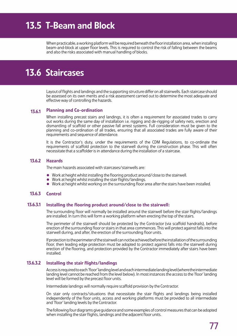
��
When practicable, a working platform will be required beneath the floor installation area, when installing beam-and-block at upper floor levels. This is required to control the risk of falling between the beams and also the risks associated with manual handling of blocks.
Layout of flights and landings and the supporting structure differ on all stairwells. Each staircase should be assessed on its own merits and a risk assessment carried out to determine the most adequate and effective way of controlling the hazards.
PlanningandCo-ordinationWhen installing precast stairs and landings, it is often a requirement for associated trades to carry out works during the same day of installation i.e. rigging and de-rigging of safety nets, erection and dismantling of scaffold or other passive fall arrest systems. Full consideration must be given to the planning and co-ordination of all trades, ensuring that all associated trades are fully aware of their requirements and sequence of attendance.
It is the Contractor’s duty, under the requirements of the CDM Regulations, to co-ordinate the requirements of scaffold protection to the stairwell during the construction phase. This will often necessitate that a scaffolder is in attendance during the installation of a staircase.
HazardsThe main hazards associated with staircases/stairwells are:
• Work at height whilst installing the flooring product around/close to the stairwell.• Work at height whilst installing the stair flights/landings.
• Work at height whilst working on the surrounding floor area after the stairs have been installed.
Control
Installingtheflooringproductaround/closetothestairwell:The surrounding floor will normally be installed around the stairwell before the stair flights/landings are installed. In turn this will form a working platform when erecting the top of the stairs.
The perimeter of the stairwell should be protected by the Contractor (via scaffold handrails), before erection of the surrounding floor or stairs in that area commences. This will protect against falls into the stairwell during, and after, the erection of the surrounding floor units.
If protection to the perimeter of the stairwell can not be achieved before the installation of the surrounding floor, then leading edge protection must be adopted to protect against falls into the stairwell during erection of the flooring, and protection provided by the Contractor immediately after stairs have been installed.
Installingthestairflights/landingsAccess is required to each ‘floor’ landing level and each intermediate landing level (where the intermediate landing level cannot be reached from the level below). In most instances the access to the ‘floor’ landing level will be formed by the precast floor units.
Intermediate landings will normally require scaffold provision by the Contractor.
On stair only contracts/situations that necessitate the stair flights and landings being installed independently of the floor units, access and working platforms must be provided to all intermediate and ‘floor’ landing levels by the Contractor.
The following four diagrams give guidance and some examples of control measures that can be adopted when installing the stair flights, landings and the adjacent floor units.
13.5 T-BeamandBlock
13.6 Staircases
13.6.1
13.6.2
13.6.3
13.6.3.1
13.6.3.2
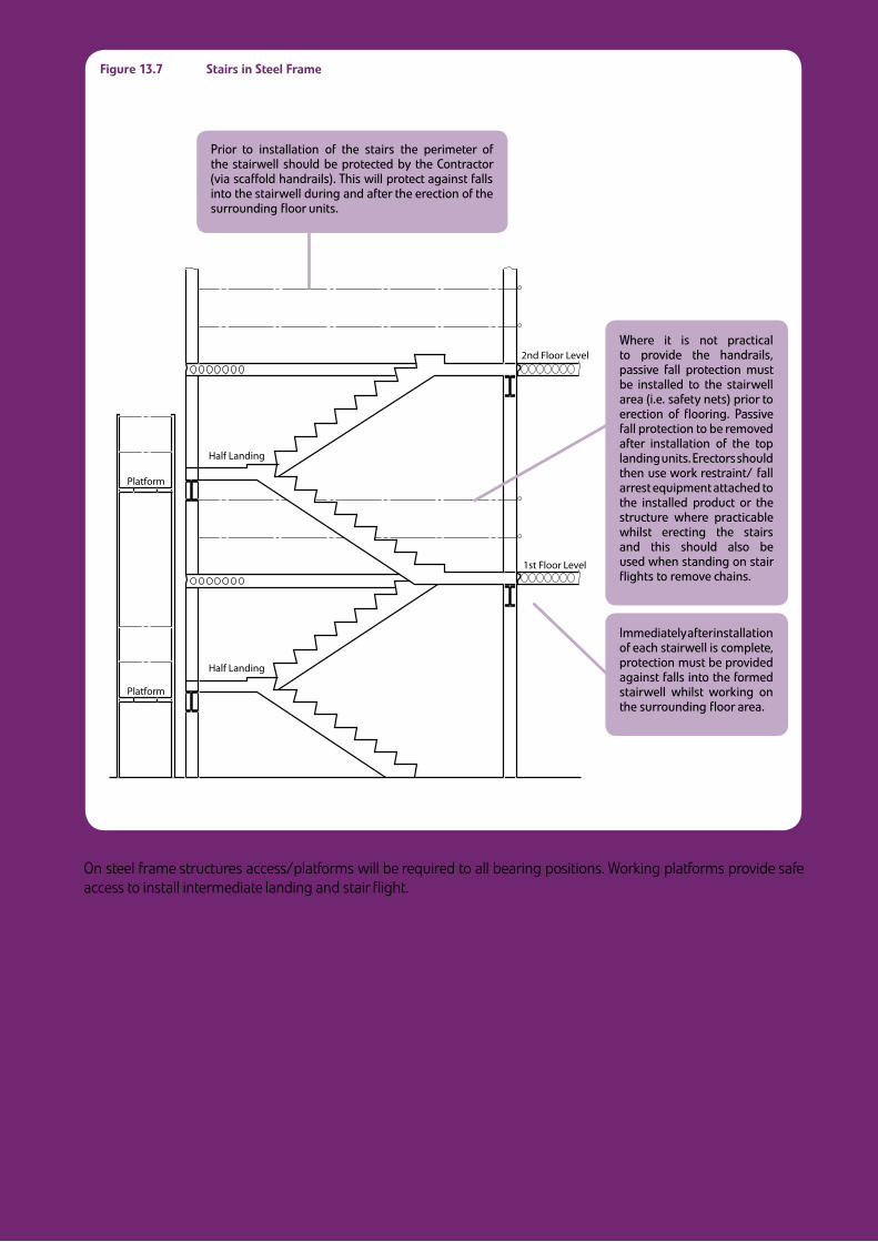
��
Platform
Platform
Half Landing
Half Landing
2nd Floor Level
1st Floor Level
Figure13.7 StairsinSteelFrame
On steel frame structures access/platforms will be required to all bearing positions. Working platforms provide safe access to install intermediate landing and stair flight.
Pr�or to �nstallat�on of the sta�rs the per�meter of the sta�rwell should be protected by the Contractor (v�a scaffold handra�ls). Th�s w�ll protect aga�nst falls �nto the sta�rwell dur�ng and after the erect�on of the surround�ng floor un�ts.
Where �t �s not pract�cal to prov�de the handra�ls, pass�ve fall protect�on must be �nstalled to the sta�rwell area (�.e. safety nets) pr�or to erect�on of floor�ng. Pass�ve fall protect�on to be removed after �nstallat�on of the top land�ng un�ts. Erectors should then use work restra�nt/ fall arrest equ�pment attached to the �nstalled product or the structure where pract�cable wh�lst erect�ng the sta�rs and th�s should also be used when stand�ng on sta�r fl�ghts to remove cha�ns.
Immed�ately after �nstallat�on of each sta�rwell �s complete, protect�on must be prov�ded aga�nst falls �nto the formed sta�rwell wh�lst work�ng on the surround�ng floor area.
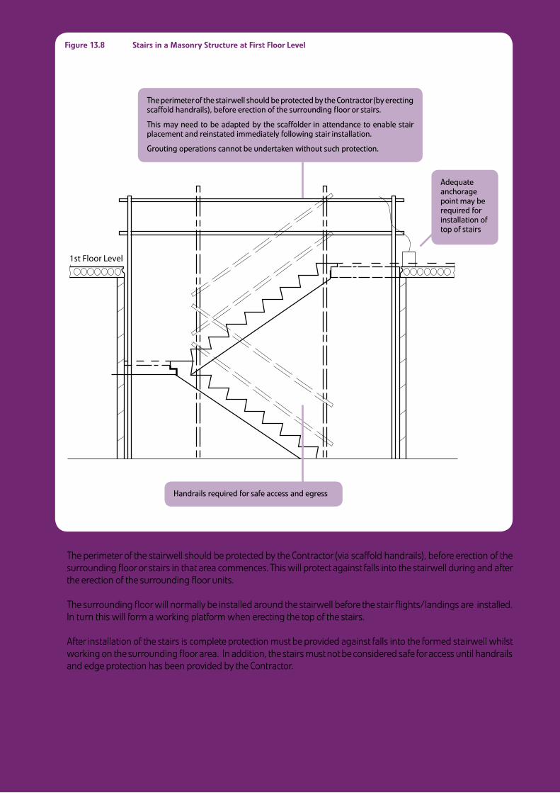
��
1st Floor Level
Figure13.8 StairsinaMasonryStructureatFirstFloorLevel
1. The perimeter of the stairwell should be protected by the Contractor (via scaffold handrails), before erection of the surrounding floor or stairs in that area commences. This will protect against falls into the stairwell during and after the erection of the surrounding floor units.
2. The surrounding floor will normally be installed around the stairwell before the stair flights/landings are installed. In turn this will form a working platform when erecting the top of the stairs.
3. After installation of the stairs is complete protection must be provided against falls into the formed stairwell whilst working on the surrounding floor area. In addition, the stairs must not be considered safe for access until handrails and edge protection has been provided by the Contractor.
The per�meter of the sta�rwell should be protected by the Contractor (by erect�ng scaffold handra�ls), before erect�on of the surround�ng floor or sta�rs.
Th�s may need to be adapted by the scaffolder �n attendance to enable sta�r placement and re�nstated �mmed�ately follow�ng sta�r �nstallat�on.
Grout�ng operat�ons cannot be undertaken w�thout such protect�on.
Handra�ls requ�red for safe access and egress
Adequate anchorage po�nt may be requ�red for �nstallat�on of top of sta�rs
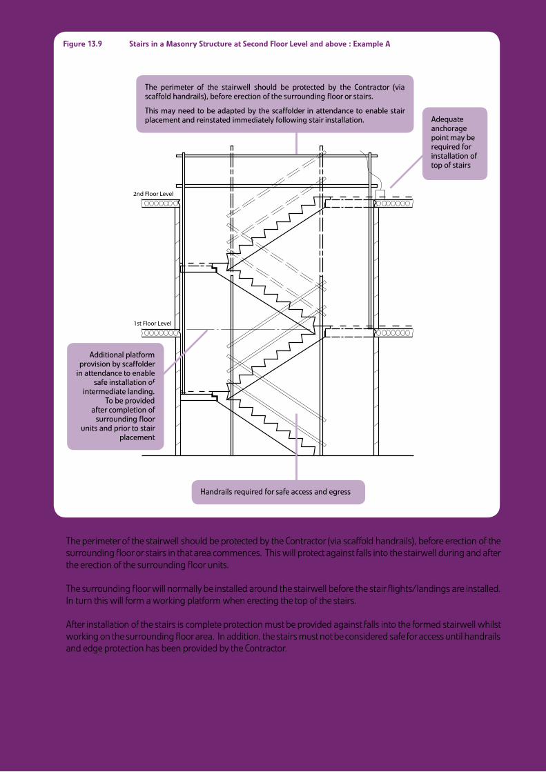
�0
2nd Floor Level
1st Floor Level
Figure13.9 StairsinaMasonryStructureatSecondFloorLevelandabove:ExampleA
1. The perimeter of the stairwell should be protected by the Contractor (via scaffold handrails), before erection of the surrounding floor or stairs in that area commences. This will protect against falls into the stairwell during and after the erection of the surrounding floor units.
2. The surrounding floor will normally be installed around the stairwell before the stair flights/landings are installed. In turn this will form a working platform when erecting the top of the stairs.
3. After installation of the stairs is complete protection must be provided against falls into the formed stairwell whilst working on the surrounding floor area. In addition, the stairs must not be considered safe for access until handrails and edge protection has been provided by the Contractor.
Handra�ls requ�red for safe access and egress
Adequate anchorage po�nt may be requ�red for �nstallat�on of top of sta�rs
The per�meter of the sta�rwell should be protected by the Contractor (v�a scaffold handra�ls), before erect�on of the surround�ng floor or sta�rs.
Th�s may need to be adapted by the scaffolder �n attendance to enable sta�r placement and re�nstated �mmed�ately follow�ng sta�r �nstallat�on.
Add�t�onal platform prov�s�on by scaffolder
�n attendance to enable safe �nstallat�on of
�ntermed�ate land�ng. To be prov�ded
after complet�on of surround�ng floor
un�ts and pr�or to sta�r placement
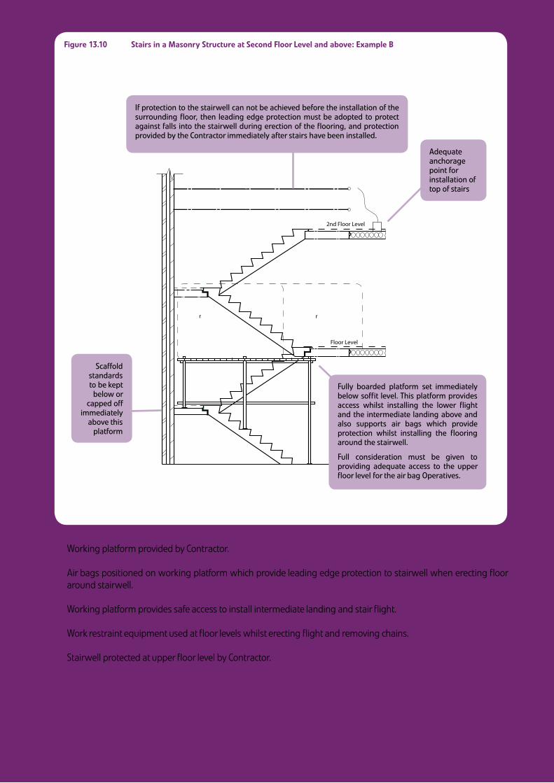
�1
2nd Floor Level
��� Floor Level
��r �����r ���
Figure13.10 StairsinaMasonryStructureatSecondFloorLevelandabove:ExampleB
1. Working platform provided by Contractor.
2. Air bags positioned on working platform which provide leading edge protection to stairwell when erecting floor around stairwell.
3. Working platform provides safe access to install intermediate landing and stair flight.
4. Work restraint equipment used at floor levels whilst erecting flight and removing chains.
5. Stairwell protected at upper floor level by Contractor.
Fully boarded platform set �mmed�ately below soffit level. Th�s platform prov�des access wh�lst �nstall�ng the lower fl�ght and the �ntermed�ate land�ng above and also supports a�r bags wh�ch prov�de protect�on wh�lst �nstall�ng the floor�ng around the sta�rwell.
Full cons�derat�on must be g�ven to prov�d�ng adequate access to the upper floor level for the a�r bag Operat�ves.
Adequate anchorage po�nt for �nstallat�on of top of sta�rs
If protect�on to the sta�rwell can not be ach�eved before the �nstallat�on of the surround�ng floor, then lead�ng edge protect�on must be adopted to protect aga�nst falls �nto the sta�rwell dur�ng erect�on of the floor�ng, and protect�on prov�ded by the Contractor �mmed�ately after sta�rs have been �nstalled.
Scaffold standards to be kept
below or capped off
�mmed�ately above th�s
platform
��
Afterthestairsandsurroundingfloorshavebeeninstalled
Immediately after installation of each stairwell is complete, protection must be provided against falls into the formed stairwell whilst working on the surrounding floor area. In addition, the stairs must not be considered safe for access until handrails and edge protection has been provided by the Contractor.
MultiStoreyStairCores
Special consideration must be given at design and planning stage to the provision of cast in anchorage points to aid scaffold arrangements and precast component installation.
The Contractor has a duty to ensure that all delivery vehicles are offloaded safely.
Where an Operative is required to access the trailer to unload the product there is a significant risk of injury from falls. Work at height on the trailer, and on the load, should therefore be avoided where reasonably practical.
Where work at height on the trailer and load cannot be avoided, then the Contractor should liaise with the Precast Installer and carry out an assessment of the site conditions, and the hierarchy of control outlined in the Work at Height Regulations should be applied to reduce the risks of injury due to falls, as far as is reasonably practicable.
Control measures range from working platform gantries, handrail systems, air bag systems, safety netsystems, personal work restraint systems and personal fall arrest systems. Such systems should be adopted where reasonably practical. The most effective system to be used will largely depend upon the site conditions, the vehicle and the size, height and type of loads being delivered.
All such safety systems will require careful planning. The Contractor should liaise with the Precast Installer and plan the offloading positions. The Contractor should also consider the Site Traffic Management Plan, other trades and deliveries and ensure that adequate arrangements have been made to accommodate the system being used. Such planning must ensure that the offloading position is within reach of the specified crane, has adequate space for the installation and has adequate ground bearing capacity.
All systems must be examined/inspected by a competent person and used in accordance with the manufacturer’s recommendations and should be visually inspected before use.
Work at height on the trailer should be avoided wherever possible, but if it is not, safe access to and egress from the trailer is essential. Where this is still necessary, suitable in build steps or secured ladders/handholds should be used.
13.6 Staircases
13.7 FallsfromDeliveryVehicles
13.6.4
13.6.5
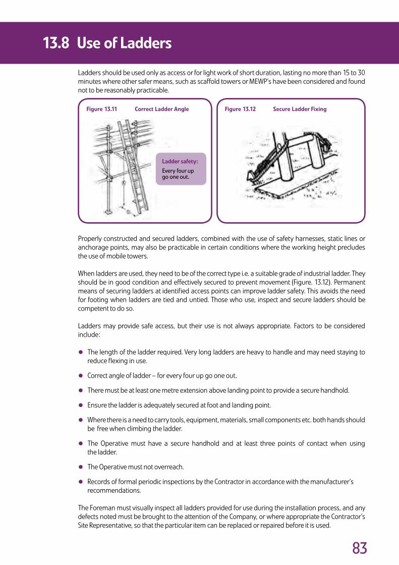
��
Ladders should be used only as access or for light work of short duration, lasting no more than 15 to 30 minutes where other safer means, such as scaffold towers or MEWP’s have been considered and found not to be reasonably practicable.
Properly constructed and secured ladders, combined with the use of safety harnesses, static lines or anchorage points, may also be practicable in certain conditions where the working height precludes the use of mobile towers.
When ladders are used, they need to be of the correct type i.e. a suitable grade of industrial ladder. They should be in good condition and effectively secured to prevent movement (Figure. 13.12). Permanent means of securing ladders at identified access points can improve ladder safety. This avoids the need for footing when ladders are tied and untied. Those who use, inspect and secure ladders should be competent to do so.
Ladders may provide safe access, but their use is not always appropriate. Factors to be considered include:
• The length of the ladder required. Very long ladders are heavy to handle and may need staying to reduce flexing in use.
• Correct angle of ladder – for every four up go one out.
• There must be at least one metre extension above landing point to provide a secure handhold.
• Ensure the ladder is adequately secured at foot and landing point.
• Where there is a need to carry tools, equipment, materials, small components etc. both hands should be free when climbing the ladder.
• The Operative must have a secure handhold and at least three points of contact when using the ladder.
• The Operative must not overreach.
• Records of formal periodic inspections by the Contractor in accordance with the manufacturer’s recommendations.
The Foreman must visually inspect all ladders provided for use during the installation process, and any defects noted must be brought to the attention of the Company, or where appropriate the Contractor’s Site Representative, so that the particular item can be replaced or repaired before it is used.
13.8 UseofLadders
Figure13.11 CorrectLadderAngle Figure13.12 SecureLadderFixing
Laddersafety:
Every four up go one out.

��
A rescue procedure must be in place on all occasions where passive fall arrest or active fall arrest are utilised and where, therefore, a fall is still possible e.g. fall into air bag, safety net, use of fall arrest safety harness. Any potential rescue procedure must be evaluated at the planning stage of the job and recorded accordingly. When planning for rescue, consideration should be given to the type of situation from which the casualty may need to be recovered, and the type of fall protection equipment that the casualty would be using. It is essential that individuals undertaking work at height are competent in appropriate rescue techniques and emergency procedures. These should form part of their initial and ongoing training. In addition to this, rescue techniques should be practiced at regular intervals, and at the start of any work situation that is unfamiliar to any of the work team.
It must be stressed that reliance upon the Emergency Services to assist with a rescue should not be part of the rescue plan. This is because there is a possible lack of appropriate equipment for the rescue, as well as the likelihood of an extended time period between the fall and the arrival of the Emergency Services.
It is also important to consider what equipment is going to be suitable for a rescue and whether it will be available on site. Equipment that could be utilised include:
• A MEWP.
• A proprietary rescue system.
• A system provided by the Contractor.
• A crane with a man riding cage.
Note
Manufacturers provide various type of suspension trauma relief equipment for use by a suspended person. These can delay the effects of suspension trauma, but they only work on conscious and able casualties; they are not an alternative to rescue.
All rescue planning and operations should address the following issues:
• The safety of the persons carrying out or assisting with the rescue.
• The anchor points to be used for the rescue equipment.
• The suitability of equipment (anchors, harnesses, attachments and connectors) that has already arrested the fall of the casualty for use during the rescue.
• The method that will be used to attach the casualty to the rescue system.
• The direction that the casualty needs to be moved to get them to the point of safety, (raising, lowering or lateral).
• The first aid needs the casualty may have with respect to injury or suspension trauma.
• The possible needs of the casualty following the rescue.
13.9 RescueProcedures
��
Suspensiontrauma
All users of personal fall protection systems, and others involved with work at a height, should be aware of the following precautions that might need to be taken in the event of a casualty being in a suspended position.
• The longer the casualty is suspended without moving, the greater the chances are of suspension trauma developing and the more serious it is likely to be. Therefore, if an injured person is suspended in a harness, the aim should be to carry out the rescue within 5 minutes. This is particularly important for a casualty who is motionless.
• A conscious casualty should be encouraged to exercise their legs gently, to stimulate circulation of the blood.
• After rescue, position the casualty in an upright position, with knees bent – DO NOT allow them to be laid flat.
• All restrictive belts and clothing should be unfastened.
• A doctor should be called immediately.
Important!Onlymovethecasualtytoafullyhorizontalpositionattheadviceofqualifiedmedicalpersonnel.Layingthecasualtydownhorizontallycouldbelifethreatening,asthebloodthathasaccumulatedinthelegsflowsabruptlyintotheheartcreatingariskofheartfailureduetooverstrain.
13.9 RescueProcedures
13.9.1
Section 14:Protection of Third Parties
Precast Flooring Federation
Sect
ion
14
Dividers.indd 14 9/6/08 15:52:45

��
The Work Area associated with the flooring erection must be designated a ‘prohibited area’ to all persons, other than those engaged in the erection of the floor. The Contractor must actively enforce this prohibition, and the Foreman must co-operate with the Contractor to ensure that fencing, gates and barriers remain secure and that notices are not removed or obscured.
The Contractor and Foreman must ensure that components are not hoisted over areas where other persons are working. This may include several levels in multi-storey work.
Operatives and Erectors engaged in the erection of the flooring must at all times execute their work with a due regard for the health and safety of other workers or persons. They must observe and comply with the Safe Working Method Statement in force on any particular contract in so far as such rules or requirements affect their operations, and they must also comply with any rules or requirements imposed by the Contractor. The Foreman must ensure that the work area is kept clean and tidy so far as this is reasonably practicable, and at the end of the working day the area should be left free of debris. Materials must be safely stacked.
14.1 OtherTradesorPersonsonSite

��
The lifting of components and materials may present a hazard to the public, especially where the delivery vehicle is unloaded from the public highway.
When unloading from the public highway, the Contractor must obtain the necessary statutory permissions and the area used for offloading must be designated a prohibited area to all persons other than those engaged in the installation of the floor.
The Contractor must provide all necessary cones, warning barriers, notices, traffic signs and lighting to allow the safe passage of pedestrians and road traffic. If deemed necessary, the prohibited area may have to be policed.
On sites where the building operations are in close proximity to public places or highways, additional care must be taken to prevent materials or debris falling from the works. Where the Contractor has provided measures to prevent such falls, or to protect the public, the Operatives and Erectors engaged in the installation of the flooring must not remove or interfere with these measures in any way.
Any debris or material which falls from delivery vehicles must be removed from the public highway or public area and the area left clean and hazard free.
When the installation involves the operation of a crane in a third party’s air space, the Contractor must obtain the necessary permissions and ensure that the appropriate steps are taken to protect third parties and the public in these areas. Loads must not be hoisted over occupied buildings. Due consideration must be given when lifting close to any adjacent occupied building.
During the course of the lifting operation the Contractor must ensure that members of the public are not in the vicinity of the suspended load or lifting equipment.
The Foreman must liaise and co-operate in all respects with the Contractor’s Site Representative to ensure compliance with any measures, provisions or rules previously agreed with the Contractor or with any statutory provisions for the protection of the public.
In the event that any of the foregoing requirements are not met, lifting should cease immediately.
14.2 MembersofthePublic

Section 15:Supplier and Sub-Contractor Competency Assessment
Employing companies must assess suppliers and installers and satisfy themselves that they are competent to carry out the proposed work safely, in accordance with the CDM Regulations 2007 and its approved Code of Practice. This is to include suppliers and installers of safety equipment and installation companies.
Precast Flooring Federation
Sect
ion
15
Dividers.indd 15 9/6/08 15:52:45

�0
Guidance on how to assess individuals and organisations is given in the CDM Regulations 2007 Approved Code of Practice in the section entitled Competence and Training and in Appendix A.
15.1 AssessmentCriteria

�1
PRECASTFLOORINGFEDERATIONSTANDARDHEALTH,SAFETYANDWELFAREATTENDANCES
REQUIREDONSUB-CONTRACTSFORTHESUPPLYANDFIXINGOFPRECASTCONCRETEFLOORINGANDCOMPONENTS
This document forms part of and should be read in conjunction with the PFF Code of Practice for Safe Erection of Precast Concrete Flooring, available from:
The Precast Flooring Federation, 60 Charles Street, Leicester, LE1 1FB.www.precastfloors.info
The Attendances contained herein shall be provided on site by the Contractor for the Precast Flooring Sub-contractor’s use, free of charge, and shall comply with the requirements of the Health and Safety at Work Act etc. 1974 and supporting Regulations (Where no Contractor exists all references to the Contractor shall mean the Precast Flooring Sub-contractor’s client).
1. CRANEANDVEHICLEACCESSANDHARDSTANDING
The Contractor shall provide and maintain hard roads, standing and stacking areas, entirely suitable for the operations safe passage and working of personnel and plant including levelling if necessary. Maintenance of the same should take into account deterioration due to adverse weather, continued use, etc. The hardstanding for the crane must be maintained as indicated on the lifting plan, for the duration of the contract.
For the guidance of the Contractor, the Precast Flooring Sub-contractor shall provide information regarding the delivery vehicles and cranes on which his quotations are based.
Parking and/or offloading facilities for installation Operatives must be provided by the Contractor.
Where practicable, fall protection systems will be used around delivery vehicles. Planning is required by the Contractor to ensure that adequate space is made available to accommodate the system and to minimise disruption.
The Contractor shall provide and maintain any access on to site off the public highway, entirely suitable for the safe passage of lorries and cranes. Should road signs, bollards, etc. or police permission be required in connection with such access, then the provision of, or application for them, as the case may be, shall be the responsibility of the Contractor.
Where erection operations are to be carried out from the public highway, all road signs, traffic and pedestrians control, all necessary permissions, etc. shall be the responsibility of the Contractor.
Where craneage or any other type of lifting appliance is to be provided by the Contractor, he must provide an Appointed Person (BS 7121) to plan the lift unless agreed otherwise. Craneage must be adequate for the purpose and the Precast Flooring Sub-contractor shall be afforded unrestricted use whenever required, including the use of a trained Operator and Signaller where applicable.
Where craneage is working the Contractor must prevent access by any other persons to the crane’s operating area.
2. STRUCTURALOBSTRUCTIONS
The Contractor shall be responsible for the re-routing, removal and/or making safe of any obstructions (including parts of the structure such as purlins, cross-bracing and scaffold standards) which will foul or hinder a crane boom or suspended load, and also for their subsequent replacement. This must be carried out before the arrival on site of the Precast Flooring Sub-contractor. The Contractor shall also be responsible for any subsequent replacement of such items.
3. PROXIMITYHAZARDS
3.1 The Contractor must inform the Precast Flooring Sub-contractor at tender stage of any proximity hazards. Such hazardsmay include overhead electric cables, electricity substations, railway lines, airfields, waterways, environmentally protected areas, restrictions to third party air-space, basements, underground services, etc. The Contractor shall be responsible for obtaining any necessary approvals/permission from relevant authorities/owners.
AppendixA
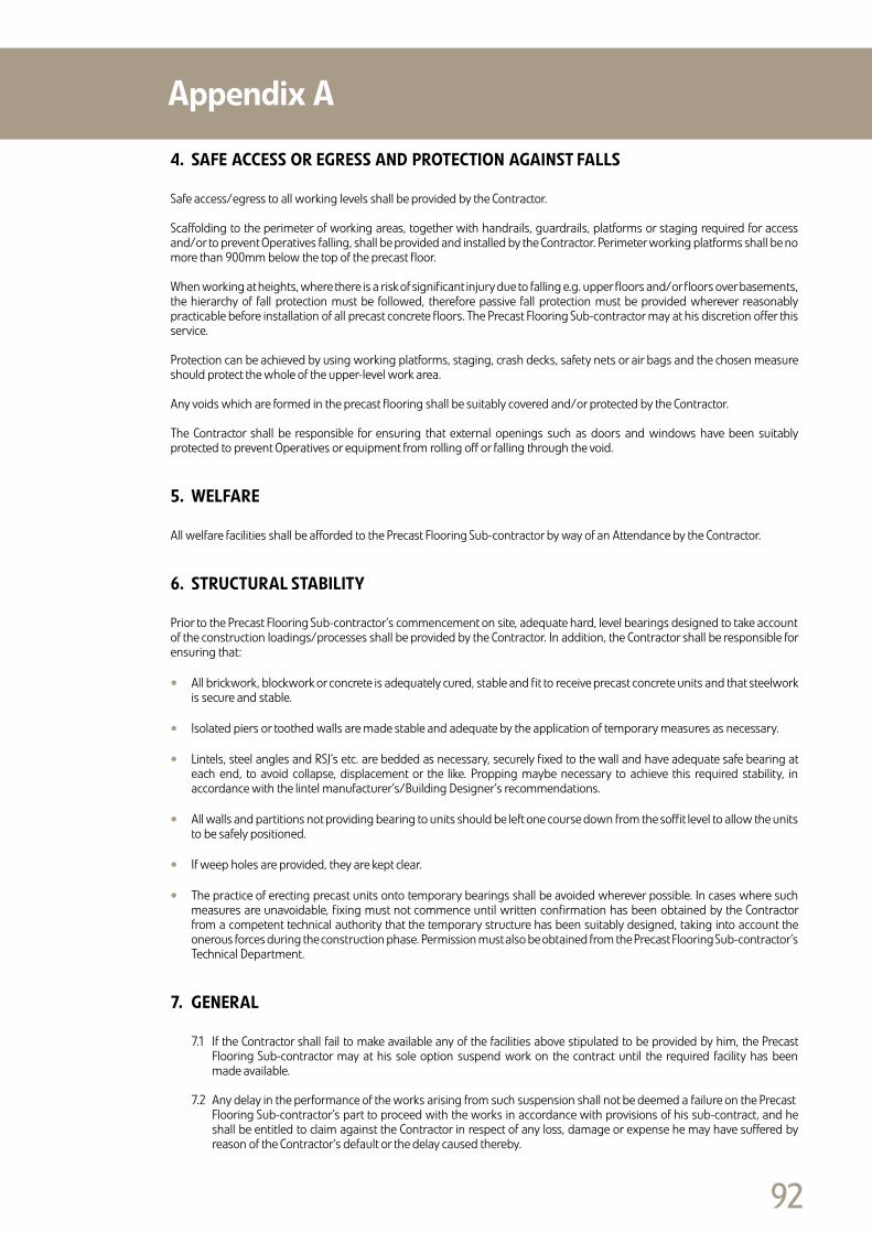
��
4. SAFEACCESSOREGRESSANDPROTECTIONAGAINSTFALLS
Safe access/egress to all working levels shall be provided by the Contractor.
Scaffolding to the perimeter of working areas, together with handrails, guardrails, platforms or staging required for access and/or to prevent Operatives falling, shall be provided and installed by the Contractor. Perimeter working platforms shall be no more than 900mm below the top of the precast floor.
When working at heights, where there is a risk of significant injury due to falling e.g. upper floors and/or floors over basements, the hierarchy of fall protection must be followed, therefore passive fall protection must be provided wherever reasonably practicable before installation of all precast concrete floors. The Precast Flooring Sub-contractor may at his discretion offer this service.
Protection can be achieved by using working platforms, staging, crash decks, safety nets or air bags and the chosen measure should protect the whole of the upper-level work area.
Any voids which are formed in the precast flooring shall be suitably covered and/or protected by the Contractor.
The Contractor shall be responsible for ensuring that external openings such as doors and windows have been suitably protected to prevent Operatives or equipment from rolling off or falling through the void.
5. WELFARE
All welfare facilities shall be afforded to the Precast Flooring Sub-contractor by way of an Attendance by the Contractor.
6. STRUCTURALSTABILITY
Prior to the Precast Flooring Sub-contractor’s commencement on site, adequate hard, level bearings designed to take accountof the construction loadings/processes shall be provided by the Contractor. In addition, the Contractor shall be responsible for ensuring that:
• All brickwork, blockwork or concrete is adequately cured, stable and fit to receive precast concrete units and that steelwork is secure and stable.
• Isolated piers or toothed walls are made stable and adequate by the application of temporary measures as necessary.
• Lintels, steel angles and RSJ’s etc. are bedded as necessary, securely fixed to the wall and have adequate safe bearing at each end, to avoid collapse, displacement or the like. Propping maybe necessary to achieve this required stability, in accordance with the lintel manufacturer’s/Building Designer’s recommendations.
• All walls and partitions not providing bearing to units should be left one course down from the soffit level to allow the units to be safely positioned.
• If weep holes are provided, they are kept clear.
• The practice of erecting precast units onto temporary bearings shall be avoided wherever possible. In cases where such measures are unavoidable, fixing must not commence until written confirmation has been obtained by the Contractor from a competent technical authority that the temporary structure has been suitably designed, taking into account the onerous forces during the construction phase. Permission must also be obtained from the Precast Flooring Sub-contractor’s Technical Department.
7. GENERAL
7.1 If the Contractor shall fail to make available any of the facilities above stipulated to be provided by him, the Precast Flooring Sub-contractor may at his sole option suspend work on the contract until the required facility has been made available.
7.2 Any delay in the performance of the works arising from such suspension shall not be deemed a failure on the Precast Flooring Sub-contractor’s part to proceed with the works in accordance with provisions of his sub-contract, and he shall be entitled to claim against the Contractor in respect of any loss, damage or expense he may have suffered by reason of the Contractor’s default or the delay caused thereby.
AppendixA

��
PFF/HS–CDM2MARCH2007
PRECAST FLOORING FEDERATION CONSTRUCTION (DESIGN AND MANAGEMENT)REGULATIONS2007
Installing precast concrete floors is a high risk activity which usually involves the use of cranes and Operatives working at heights.
The purpose of the following information is to highlight some of the points covered in the ‘Code of Practice for Safe Erection of Precast Concrete Flooring and Associated Components, to assist Engineers, Designers, Contractors and CDM Co-ordinators in meeting the requirements of the CDM Regulations. More detailed information is provided in the Code of Practice, in particular Section 4 – Design Stage Considerations. In the text which follows the Precast Designer is not the Building Designer.
1. THEEXISTINGENVIRONMENT 1.1 The sizes and weights of the components will determine the method of offloading and placing the units. The precast units are usually delivered to site on articulated lorries; narrow roads or restricted access may necessitate the use of rigid lorries.
1.2 Pedestrian and traffic management measures should be considered, especially if the delivery lorries are offloaded from the public highway.
1.3 Adequate access to the work area must be provided to safely support the loads imposed by the crane’s outriggers. Excavations, underground services, drains and basements are a hazard and strengthening may be required.
1.4 The presence of power lines, railway tracks, trees or overhead structural obstructions may hinder the operation of cranes. On restricted sites it may be necessary for loads to be lifted over adjacent land and buildings. In these circumstances, permission should be obtained to operate within the airspace of third parties.
2. DESIGNANDPLANNING 2.1 The regulations require that a designer’s competence has to be considered in the light of health and safety. Members of the Precast Flooring Federation can demonstrate their experience and competence in the design and manufacture of precast flooring.
2.2 To assist the Precast Designer, the following information should be provided at tender stage:
• Pre-construction information / Construction Phase Health and Safety Plan
• Design loads including finishes and imposed loads
• Drawings showing the supporting structure for the precast units and direction of span
• Phasing or sequencing of the works
• Site and services plan
2.3 Designers must take into account stability of the structure during the installation of precast units:
• The design should allow for the removal, prior to the installation of the units, of overhead obstructions such as purlins or bracing, that are likely to foul or hinder the crane boom or suspended load.
• Precast units can be heavy. Bearings must be adequate and be robust enough to withstand normal unit fixing operations including landing and barring.
• Lintels or steel beams must be securely fixed and have adequate safe bearing at each end to avoid overturning, excessive deflection or collapse when the precast units are placed.
• Consideration must be given to the unequal loading of unrestrained walls, steel beams or lintels when precast units are being placed.
• The practice of erecting precast units onto temporary bearings should be avoided wherever possible. In cases where such measures are unavoidable the temporary structure must be designed and erected by a competent person provided by the Contractor.
AppendixB

��
2.4 When an order is placed for the precast concrete units, the Contractor should provide the Precast Flooring Sub-Contractor with the following information:
• Any relevant amendments to the Health and Safety Plan.
• Fully dimensioned ‘Construction Issue’ drawings, detailing the supporting structure for the floors and any other aspects which may affect the floor design.
• Loadings, including type and location of partitions, types of finish, etc.
• Positions and sizes of all holes, notches or rebates required in the flooring.
• Provisional sequencing and programme dates.
• Where working in the vicinity of rail tracks, underground railway lines, or energy supply structures such as power cables, all permissions that are required from owners or controllers are to be given in advance, along with any instructions for the safe working of the Installer.
3. CONSTRUCTIONPHASE 3.1 The installation of precast concrete units should only be undertaken by specialists. Members of the Precast Flooring Federation only employ Erectors who are trained competent and experienced in this work.
3.2 The Contractor must ensure that the Precast Flooring Federation Standard Health, Safety and Welfare Attendances have been provided.
3.3 Installing precast floors is a high risk operation and should not be undertaken without the provision of a job specific method statement and risk assessments which may address some or all of the following activities:
• Manual Handling • Working at heights with risk of personnel/objects falling • Working with cranes • Handling or cutting concrete products, working with wet concrete or mortar
3.4 The Principal Contractor must ensure that other trades and the public are kept out of the working area covered by cranes used for installing the precast units.
3.5 A major consideration for the Building Designer and Contractor should be the stability of the structure during the installation of the precast concrete units:
• Sufficient time must be allowed for masonry mortar to mature enough to achieve adequate strength and stiffness. • The designer should give consideration to the provision of adequate wall thickness, particularly where shared bearings occur on lightweight masonry blocks. • Consideration should be given to the proposed sequence of construction and the effects of any temporary removal of parts of the structure to facilitate the safe installation of the precast units.
Sufficient time must be allowed for a grouted floor to mature prior to loading out with materials, which should not exceed the load for which the floor has been designed. Advice should be sought prior to the storage of unfixed materials on the floors by following trades.
4. THEHEALTHANDSAFETYFILE 4.1 The Precast Flooring Sub-Contractor will provide ‘as installed’ drawings at completion of the installation, showing any changes from the original floor layout. Thereafter, the Contractor will be responsible for recording departures from the ‘as installed’ drawings.
4.2 The flooring layout drawings will detail the loads for which the floors have been designed.
4.3 Care should be exercised to ensure that during the Construction Phase and during the life of the building, the design loads are not exceeded and that further holes or chases are not made in the flooring without reference to the flooring manufacturer or a competent person.
Most precast floors are constructed from prestressed units and advice on demolition should be sought from a competent person, with access to the Health and Safety File.
AppendixB