pre-planning guide for the linear burner system · anemia, those under the influence of alcohol,...
TRANSCRIPT

PRE-PLANNING GUIDE for the Linear Burner SystemGAS PRESSURESPARK products are engineered, safety tested and certified to function properly within a specific gas supply pressure range. It is CRITICALLY IMPORTANT that the gas lines be properly sized and installed by a licensed plumber and/or certified gas technician to deliver continuous operating pressure within the range stated for each product.Several variables should be taken into consideration when sizing the gas lines:
Overall peak demand on the system.Length of runNo log lighter valves should be included in the system (if one is preexisting it must
be removed) Failure to supply minimum running pressure will cause the unit to perform poorly- if at all- less than minimum supply pressure is not covered under warranty.
ATTENTIONSPARK Modern Fires wants to help you achieve your fireplace vision.We will review your planned installation of your LINEAR BURNER OUTDOOR. Please provide plan view and section drawings electronically, along with a rendering of the finishing details, and we will help you plan it properly.
· PROPER VENTILATIONCritical notes and details are available in this guide for proper and safe installation of the Linear Burner System Outdoor. Proper ventilation air requirements and details on how to provide this air to the underside of the burners is provided in the following pages.
A minimum requirement of (1) 4” round (+12 sq inches) ventilation air supply for a 2’or 3’ burner. At least (2) or more 4” round (each +12 sq inches) fresh air supplies required for larger burners.
· ELEVATIONAll installations above 4500 feet above sea level require special consideration and possible product de-regulating at the factory. If you are planning to use a SPARK product above 4500 ft it is critical to indicate this early in your investigation/ product selection and certainly men-tion it in the order process.
SAFETYINFORMATION
WARNINGS
Natural Gas: Natural gas is odor-less. An odor making agent is added to the gas. The odor helps you detect a gas leak. However, the odor added to the gas can fade. Gas may be present even though no odor exists.Make certain you read and under-stand all warnings. Keep this manual for reference. It is your guide to safe and proper operation of this appliance.
1. This appliance, as supplied, isonly for use with the type ofgas indicated on the ratingplate.
3. Keep the appliance area clearand free from combustiblematerials, gasoline and otherflammable vapors and liquids.
4. Do not burn solid fuel in thefireplace after installing theappliance. Do not use thisappliance to cook food orburn paper or other objects.
5. Children and adults should bealerted to the hazards of
materials
carefully supervised whenthey are in the area of the appliance.
8. The appliance, when installed,must be electrically groundedin accordance with local codesor, in the absence of localcodes, with the National Elec-
ely call a qualif
any part of the
under water.10. Inspect the burner before each
LOCAL CODES
. Follow local codes.
* American National StandardsInstitute, Inc., 1430Broadway, New York,NY 10018
* National Fire ProtectionAssociation, Inc.,Batterymarch Park, Quincy,MA 02269.
WARNING: Any change to this appliance or its controls can be dangerous.
IMPORTANT: The applianceshould be inspected beforeuse and at least annually bya quilified service person.More frequent cleaning maybe required as necessary. Itis imperative that the controlcompartment, burners andcirculating air passageways of the appliance be kept clean.
DANGER: Carbon mo-noxide poisoning may lead to death!
HIGH ALTITUDEINSTALLATIONS:
7. Young children should be
should not be hungfrom the appliance, or placedon or near the appliance.
6. Clothing or other flammable
highsurface temperatures andshould stay away to avoidburns or clothing ignition.
trical Code, ANSI/NFPA 70or the Canadian ElectricalCode, CSA C22.1, ifapplicable.
The burner must be replacedprior to the appliance being putinto operation if it is evident thatthe burner is damaged. Pleaserefer to "Illustrated parts List"for the replacement burner partnumber.
The appliance is rated forinstallations up to 4500’ (1372 m)above sea level. Above 4500’ theappliance must be de- rated at thefactory for the appropriate altitude.
theappliance. Only a qualifiedservice person should install,service, or repair appliance.
11. Turn the appliance off and letcool before servicing, install-ling, or repairing. Any guardor other protective deviceremoved for servicing theappliance must be replacedprior to operating
iedservice techn ician to inspectthe room appliance and toreplace controlsystem and any gas controlwhich has been
9. Do not use appliance if anypart has been under water.Imm ediat
2. When an appliance is for con- nection to a fixed piping system, the installation must conform with local codes, or in the ab- sence of local codes with the National Fuel Gas Code, ANSI Z223.1/NFPA 54, or Interna- tional Fuel Gas Code, Natural Gas and Propane Installation Code, CSA B149.1, or Pro- pane Storage and Handling Code, B149.2, as applicable.
use of LBS-OD.
In the absence of local codes, use the latest edition of The National Fuel Gas Code ANSI Z223.1/NFPA54 available from:
Install and use LBSOD withcare.
Carbon Monoxide Poisoning: Early signs of carbon monoxide poisoning resemble the flu, with headaches, dizziness, or nausea. If you have these signs, the LBS- OD may not be working properly. Get fresh air at once! Have the LBSOD serviced. Some people are more affected by carbon monoxide than others. These include pregnant women, people with heart or lung disease or anemia, those under the influence of alcohol, and those at high altitudes.
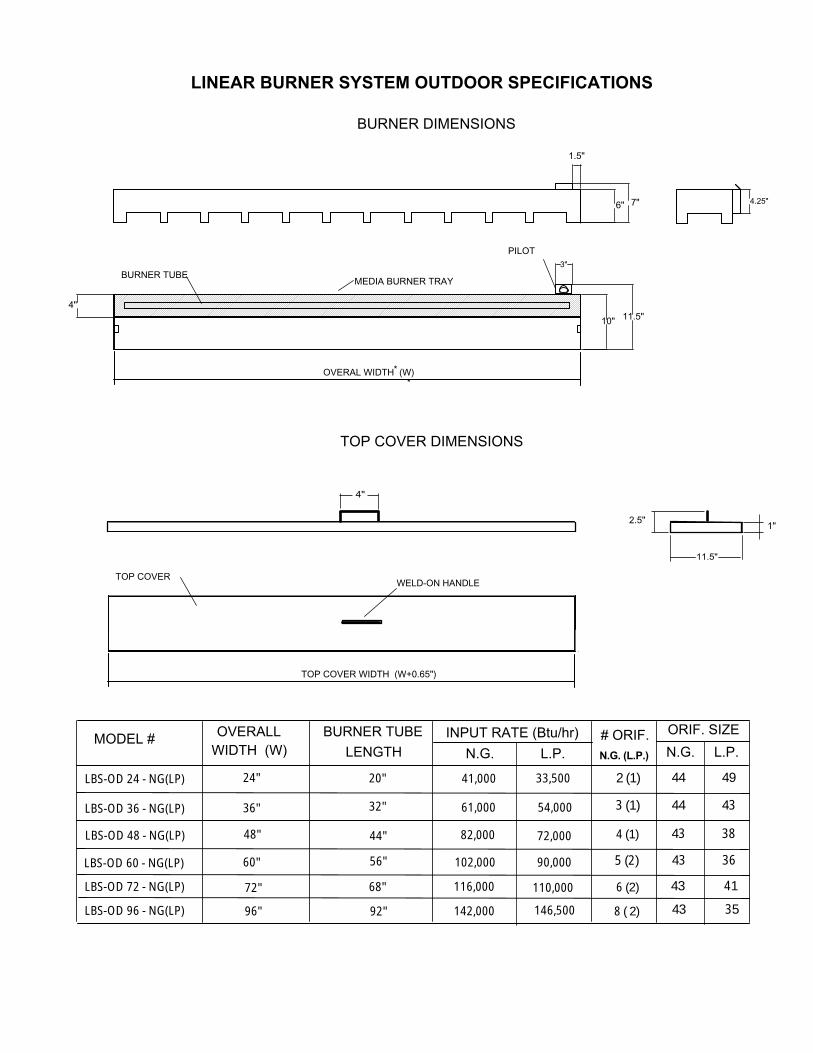
LINEAR BURNER SYSTEM OUTDOOR SPECIFICATIONS
MEDIA BURNER TRAY
PILOT
BURNER TUBE
10"
4"11.5"
3"
4.25"6" 7"
1.5"
OVERAL WIDTH (W)*
BURNER DIMENSIONS
TOP COVER DIMENSIONS
*
TOP COVERWELD-ON HANDLE
TOP COVER WIDTH (W+0.65")
11.5"
1"2.5"
4"
N.G. (L.P.)
OVERALL
24" 41,000 33,500
2 (1) 44 49
MODEL #N.G. L.P.
# ORIF. ORIF. SIZEN.G. L.P.
LBS-OD 24 - NG(LP)
LBS-OD 48 - NG(LP)
LBS-OD 72 - NG(LP)
LBS-OD 96 - NG(LP)
48"
72"
96"
BURNER TUBE LENGTH
20"
44"
68"
92"
82,000 72,000
116,000 110,000
142,000 146,500
4 (1) 43 38
6 (2) 43 41
8 ( 2) 43 35
WIDTH (W)
LBS-OD 36 - NG(LP)
LBS-OD 60 - NG(LP)
36"
60"
32"
56"
61,000
102,000
54,000
90,000
3 (1)
5 (2)
44 43
43 36
INPUT RATE (Btu/hr)
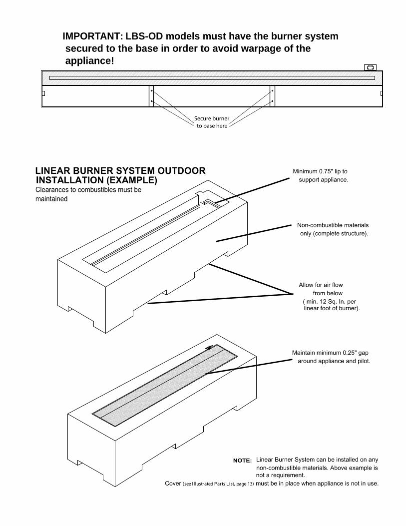
�Maintain minimum 0.25" gap
around appliance and pilot.
Minimum 0.75" lip tosupport appliance.
Non-combustible materialsonly (complete structure).
Allow for air flowfrom below
NOTE: Linear Burner System can be installed on anynon-combustible materials. Above example is not a requirement.
Cover (see I llustrated Parts List, page 13) must be in place when appliance is not in use.
( min. 12 Sq. In. perlinear foot of burner).
Secure burner to base here
LINEAR BURNER SYSTEM OUTDOOR
I NSTALLATION (EXAMPLE)Clearances to combustibles must bemaintained
IMPORTANT: LBS-OD models must have the burner system secured to the base in order to avoid warpage of the appliance!
PRODUCT ASSEMBLY
2. Connect the Burner Assemblyto gas supply using suppliedflex connector and shutoffvalve.
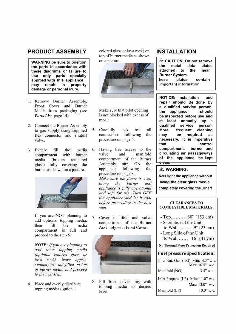
3. Evenly fill the mediacompartment with burnermedia (broken temperedglass) fully covering theburner as shown on a picture.
If you are NOT planning to add optional topping media, then fill the media compartment in full and proceed to the step 5.
NOTE: If you are planning to add some topping media (optional colored glass or lava rock), leave appro-ximately ¾” not filled on top of burner media and proceed to the next step.
4. Place and evenly distributetopping media (optional
colored glass or lava rock) on top of burner media as shown on a picture.
Make sure that pilot opening is not blocked with excess of media.
5. Carefully leak test allconnections following theprocedure on page 5.
7. Cover manifold and valvecompartment of the BurnerAssembly with Front Cover.
8. Fill front cover tray withtopping media to desiredlevel.
INSTALLATIONCAUTION: Do not remove
the metal data plates attached to the inear Burner System. hese plates contain important information.
NOTICE: Installation and repair should Be done By a qualified service person. the appliance should be inspected before use and at least annually by a qualified service person. More frequent cleaning may be required as necessary. It is imperative that control compartment, burner and circulating air passageways of the appliance be kept clean.
CLEARANCES TOCOMBUSTIBLE MATERIALS:
- Top……… 60” (153 cm)- Short Side of the Unit
to Wall ……. . 9” (23 cm)- Long Side of the Unit
to Wall …… 16” (41 cm)No Thermal Floor Protection Required
Fuel pressure specification:
WARNING be sure to position the parts in accordance with these diagrams or failure to use only parts specially approed with this appliance may result in property damage or personal inury.
WARNING: Neer light the appliance without haing the clear glass media
completely covering the urner!
1. Remove Burner Assembly,Front Cover and BurnerMedia from packaging (seeParts List, page 14).
6. Having free access to thevalve and manifoldcompartment of the BurnerAssembly turn ON theappliance following theprocedure on page 8.Make sure the flame is evenalong the burner andappliance is fully operationaland safe for use. Turn OFFthe appliance and let it coolbefore proceeding to the nextstep.
Inlet Nat. Gas (NG) Min: 4.5” w.c.Max: 10.5" w.c.
Inlet Propane (LP) Min: 11.0” w.c.Max: 13.0" w.c.
Manifold (LP) 10.0” w.c.
Manifold (NG) 3.5” w.c.

FIREPLACE INSTALLATION
CHECK GAS TYPE
Use proper gas type for the fireplace you are installing. If you have conflicting gas type, do not install fireplace. See dealer where you purchased the fireplace for proper fireplace for your gas type or conversion kit.
INSTALLING GAS PIPING TO FIREPLACE / BURNER SYSTEM LOCATION
INSTALLATION ITEMS NEEDED
Before installing fireplace and burner system, make sure you have the items listed below.
• External regulator (supplied by installer) • Piping (check local codes) • Sealant (resistant to propane/LP gas)• Equipment shutoff valve* • Test gauge connection* • Sediment trap (recommended)• Tee joint • Pipe wrench• approved flexible gas line with gas connector (if allowed by local codes — not provided)
* A CSA design-certified equipment shutoff valve with 1/8" NPT tap is an acceptable alternative to test gauge connection.Purchase the CSA design-certified equipment shutoff valve from your dealer.
External Regulator
100 lb. (min) Propane/LP Supply Tank
Vent Pointing Down When using copper or flex connectors use only fittings approved
for gas connections. The gas control inlet is 3/8" NPT.
A qualified installer or service person must connect appliance to gas supply. Follow all local codes.
A qualified installer or service person must
WARNING
For propane/LP units, never connect fireplace directly to the propane/LP supply. This burner system requires an external regulator (not supplied). Install the external regulator between the burner system and propane/LP supply.
CAUTION
Use only new black iron or steel pipe. Internally tinned copper or copper tubing can be used per National Fuel Code, section 2.6.3, providing gas meets hydrogen sulfide limits, and where permitted by local codes. Gas piping system must be sized to provide minimum inlet pressure (listed on data plate) at the maximum flow rate (BTU/hr). Undue pressure loss will occur if the pipe is too small.
CAUTION
Figure 1 - External Regulator with Vent Pointing Down (Propane/LP Only)
For propane/LP connections only, the installer must supply an external regulator. The external regulator will reduce incoming gas pressure. You must reduce incoming gas pressure to between 11 and 13 inches of water. If you do not reduce incoming gas pressure, burner system regulator damage could occur. Install external regulator with the vent pointing down as shown in Figure 1. Pointing the vent down protects it from freezing rain or sleet.