pre- feasibility report -...
TRANSCRIPT

PRE- FEASIBILITY REPORT(In terms of provision of EIA Notification 2006)
The Proposed Expansion of Dariba
Zinc Smelter (2,50,000Lead Smelter (1
Captive Power Plant (2 x 85 MW to 3 X 85 MW)
HINDUSTAN
DaribaDariba
Ministry of Environment Forest & Climate Change
FEASIBILITY REPORT(In terms of provision of EIA Notification 2006)
For
Proposed Expansion of Dariba Smelter Complex
,50,000 TPA to 5,00,000 TPA + Fumer Plant)1,25,000 TPA to 1,50,000 TPA) and
Captive Power Plant (2 x 85 MW to 3 X 85 MW)
By:
HINDUSTAN ZINC LIMITED,
Dariba Smelter Complex, Dariba – 313 211, Rajsamand,
Rajasthan
To:
inistry of Environment Forest & Climate Change
(MoEF & CC) New Delhi
December, 2017
FEASIBILITY REPORT (In terms of provision of EIA Notification 2006)
Complex
TPA + Fumer Plant) and
inistry of Environment Forest & Climate Change
Proposed Expansion of Dariba Smelter Complex TPA + Fumer Plant), Lead Smelter (0.125 Million TPA to 0.150 Million TPA) and Captive Power Plant (2 x 85 MW to 3 X 85 MW) at Village Dariba , Relmagra, District - R
CHAPTER 1: INTRODUCTION
1.1 Preamble
1.2 Identification of Project
1.3 Need for the Project and Its Importance
1.4 Legal Aspects
CHAPTER 2: PROJECT DESCRIPTION
2.1 Project Description
2.2 Project Details
2.3 Process Description
CHAPTER 3: SITE ANALYSIS
3.1 Connectivity
3.2 Land use and Land ownership
3.3 Topography
3.4 Existing Infrastructure
CHAPTER 4: PLANNING BRIEF
4.1 Planning Concept
4.2 Population Projection
4.3 Land use planning
4.4 Assessment of Infrastructure Demand (Physical & Social)
4.5 Amenities/Facilities
CHAPTER 5: REHABILITATION AND RESETTLEMENT (R & R) PLAN
CHAPTER 6: PROJECT SCHEDULE AND COST ESTIMATES
6.1 Time Schedule for the Project
6.2 Project Cost
CHAPTER 7: ANALYSIS OF PROPOSAL
7.1 Financial and social benefits
7.2 Environment Friendly Project
CHAPTER 8: CONCLUSION
8.1 Conclusion
Proposed Expansion of Dariba Smelter Complex - Zinc Smelter (0.25 to 0.50 Million TPA + Fumer Plant), Lead Smelter (0.125 Million TPA to 0.150 Million TPA) and Captive Power Plant (2 x 85 MW to 3 X 85 MW) at Village Dariba ,
Rajsamand, Rajasthan
TABLE OF CONTENTS
CHAPTER 1: INTRODUCTION
Identification of Project & Project Proponent
Need for the Project and Its Importance
CHAPTER 2: PROJECT DESCRIPTION
CHAPTER 3: SITE ANALYSIS
Land use and Land ownership
Existing Infrastructure
CHAPTER 4: PLANNING BRIEF
Population Projection
Assessment of Infrastructure Demand (Physical & Social)
: REHABILITATION AND RESETTLEMENT (R & R) PLAN
SCHEDULE AND COST ESTIMATES
Time Schedule for the Project
: ANALYSIS OF PROPOSAL
Financial and social benefits
Environment Friendly Project
Zinc Smelter (0.25 to 0.50 Million TPA + Fumer Plant), Lead Smelter (0.125 Million TPA to 0.150 Million TPA) and Captive Power Plant (2 x 85 MW to 3 X 85 MW) at Village Dariba , Tehsil -
2 | P a g e
3
4
4
5
7
8
9
16
22
56
57
57
57
57
59
60
60
60
60
60
61
63
64
64
65
66
66
67
68

Proposed Expansion of Dariba Smelter Complex TPA + Fumer Plant), Lead Smelter (0.125 Million TPA to 0.150 Million TPA) and Captive Power Plant (2 x 85 MW to 3 X 85 MW) at Village Dariba , Relmagra, District - R
Proposed Expansion of Dariba Smelter Complex - Zinc Smelter (0.25 to 0.50 Million TPA + Fumer Plant), Lead Smelter (0.125 Million TPA to 0.150 Million TPA) and Captive Power Plant (2 x 85 MW to 3 X 85 MW) at Village Dariba ,
Rajsamand, Rajasthan
CHAPTER
INTRODUCTION
Zinc Smelter (0.25 to 0.50 Million TPA + Fumer Plant), Lead Smelter (0.125 Million TPA to 0.150 Million TPA) and Captive Power Plant (2 x 85 MW to 3 X 85 MW) at Village Dariba , Tehsil -
3 | P a g e
CHAPTER - 1
INTRODUCTION
Proposed Expansion of Dariba Smelter Complex TPA + Fumer Plant), Lead Smelter (0.125 Million TPA to 0.150 Million TPA) and Captive Power Plant (2 x 85 MW to 3 X 85 MW) at Village Dariba , Relmagra, District - R
1.1 PREAMBLE
1.1 About HZL
Hindustan Zinc Limited (HZL) is an India
mining and smelting of
segments are mining and smelting of
Company's operations include five
Lead Smelter, a Zinc-Lead
plant and over six captive power plants in the state of Rajasthan. In addition, the Company also has a rock
and Zinc, Lead, Silver
Uttarakhand. The Company also has wind power plants in the States of
Rajasthan, Gujarat, Karnataka, Tamil Nadu and Maharashtra. It has a metal
production capacity of over one million tons per annum with its key
mines in Rampura Agucha and Sindesar
Chanderiya and Dariba, all in the state of Rajasthan
1.2 Identification of Project & Project Proponent
Hindustan Zinc Ltd. is one of the largest Leading producer of silver with more than 60 years of experience in Mining &
Smelting. Reserves & Resources of about 404.4 MT as on 31
sufficient for more than 25 years of mine life. Environment Clearance Capacities
Ore Production- 16.55 MTPA,
TPA, Silver- 772 TPA. Captive Thermal Power generation
power 35 MW & Wind power 274 MW and 16.2 MW solar power plant.
Development Mechanism (CDM) projects on waste heat recovery & win
have an annual Certified Emission Reduction potential of over 5
CO2. Total Exchequer to Government during 2016
including Royalty, taxes and
Plant at Udaipur under PPP
water in its operations. Udaipur Smart City Ltd for another 40 MLDon 25
the quality of life and economic
operations, mainly SAKHI, MARYADA, KHUSHI campaigns, reaching over 5 lakh
people spread over 184 villages across Rajasthan.
Dariba Smelter Complex was established in the year 2010
Complex of Hindustan Zinc
MTPA) and Captive Power Plant (170 MW).
by MoEF&CC for Integrated Project at Darib
(5,00,000 TPA), Lead Smelter
expansion of Rajpura
Beneficiation Plant (9,00,000 to 12,00,000 TPA)
11011/380/2008-IA II (I) dated 4.11.2009.
Dariba Smelter Complex
The nearest railway station is Fatehnagar, about 15.5
broad gauge railway line. Plant
Udaipur, Chittorgarh, Bh
falls in Survey of India Topo
The proposed expansion of
TPA of Zinc Smelter,1,25
Proposed Expansion of Dariba Smelter Complex - Zinc Smelter (0.25 to 0.50 Million TPA + Fumer Plant), Lead Smelter (0.125 Million TPA to 0.150 Million TPA) and Captive Power Plant (2 x 85 MW to 3 X 85 MW) at Village Dariba ,
Rajsamand, Rajasthan
Limited (HZL) is an India-based company, which is engaged in the
mining and smelting of Zinc, Lead and Silver metal in India. The Company's
ining and smelting of Zinc, Lead and Silver and Wind energy. The
Company's operations include five Zinc-Lead mines, over four Zinc
Lead Smelter, seven sulphuric acid plants, a silver refinery
plant and over six captive power plants in the state of Rajasthan. In addition, the Company also has a rock-phosphate mine in Maton near Udaipur in Rajasthan
, Silver processing and refining facilities in the State of
Uttarakhand. The Company also has wind power plants in the States of
Rajasthan, Gujarat, Karnataka, Tamil Nadu and Maharashtra. It has a metal
production capacity of over one million tons per annum with its key
Agucha and Sindesar Khurd, and smelting complexes in
Chanderiya and Dariba, all in the state of Rajasthan.
f Project & Project Proponent
Ltd. is one of the largest Lead-Zinc integrated producer & a ing producer of silver with more than 60 years of experience in Mining &
Smelting. Reserves & Resources of about 404.4 MT as on 31st
sufficient for more than 25 years of mine life. Environment Clearance Capacities
16.55 MTPA, Zinc metal- 11.25 lakh TPA, Lead metal
TPA. Captive Thermal Power generation 474 MW, Waste heat
power 35 MW & Wind power 274 MW and 16.2 MW solar power plant.
Development Mechanism (CDM) projects on waste heat recovery & win
have an annual Certified Emission Reduction potential of over 5,83,685 TPA of
Total Exchequer to Government during 2016-17 was Rs.17,
including Royalty, taxes and dividend. HZL has established Sewage Treatment
Plant at Udaipur under PPP model to treat 20 MLD sewage and utilize treated
water in its operations. With the successof Phase-1,MOU has been signed with Udaipur Smart City Ltd for another 40 MLDon 25thJune 2017. Vision to enhance
the quality of life and economic wellbeing of the communities around its
operations, mainly SAKHI, MARYADA, KHUSHI campaigns, reaching over 5 lakh
people spread over 184 villages across Rajasthan.
Complex was established in the year 2010-11 in Rajpura
Zinc with Zinc Smelter (0.25 MTPA), Lead Smelter
MTPA) and Captive Power Plant (170 MW). Environment Clearance was granted
Integrated Project at Dariba, Hindustan Zinc Ltd. (
Smelter (1,25,000 TPA), Captive Power Plant (255 MW) and
Dariba Mine (6,31,000 to 9,00,000 TPA) along with
Beneficiation Plant (9,00,000 to 12,00,000 TPA) vide Letter No. J
IA II (I) dated 4.11.2009.
Complex (DSC) is located at a distance of 76 km NNE of Udaipur.
station is Fatehnagar, about 15.5 km, on Chittorgarh
broad gauge railway line. Plant is well connected by a metalled road from
Udaipur, Chittorgarh, Bhilwara and District head quarter Rajsamand. The
y of India Topo sheet No. 45/L1.
The proposed expansion of Dariba Smelter Complex is from 2,50,000
25,000 to 1,50,000 TPA of Lead Smelter and from
Zinc Smelter (0.25 to 0.50 Million TPA + Fumer Plant), Lead Smelter (0.125 Million TPA to 0.150 Million TPA) and Captive Power Plant (2 x 85 MW to 3 X 85 MW) at Village Dariba , Tehsil -
4 | P a g e
based company, which is engaged in the
ia. The Company's
and Wind energy. The
Zinc Smelters, a
, seven sulphuric acid plants, a silver refinery
plant and over six captive power plants in the state of Rajasthan. In addition, the phosphate mine in Maton near Udaipur in Rajasthan
cilities in the State of
Uttarakhand. The Company also has wind power plants in the States of
Rajasthan, Gujarat, Karnataka, Tamil Nadu and Maharashtra. It has a metal
production capacity of over one million tons per annum with its key Lead-Zinc
Khurd, and smelting complexes in Debari
integrated producer & a ing producer of silver with more than 60 years of experience in Mining &
March 2017
sufficient for more than 25 years of mine life. Environment Clearance Capacities-
metal-2.20 lakh
MW, Waste heat
power 35 MW & Wind power 274 MW and 16.2 MW solar power plant. Clean
Development Mechanism (CDM) projects on waste heat recovery & wind power
83,685 TPA of
,760 Crores,
. HZL has established Sewage Treatment
sewage and utilize treated
1,MOU has been signed with n to enhance
of the communities around its
operations, mainly SAKHI, MARYADA, KHUSHI campaigns, reaching over 5 lakh
11 in Rajpura Dariba
Smelter (0.125
Environment Clearance was granted
(Zinc Smelter
(1,25,000 TPA), Captive Power Plant (255 MW) and
Dariba Mine (6,31,000 to 9,00,000 TPA) along with
vide Letter No. J-
is located at a distance of 76 km NNE of Udaipur.
km, on Chittorgarh-Udaipur
metalled road from
Rajsamand. The plant
0,000 to 5,00,000
from 170 MW
Proposed Expansion of Dariba Smelter Complex TPA + Fumer Plant), Lead Smelter (0.125 Million TPA to 0.150 Million TPA) and Captive Power Plant (2 x 85 MW to 3 X 85 MW) at Village Dariba , Relmagra, District - R
(2 X 85 MW) to 255 MW (3 X 85 MW) of Captive Power Plant
to install Fumer plant (pyro metallurgical process) within leaching circuit of
Smelter to eliminate the generation of Jarosite, which is presently stabilized with
lime and cement to convert into stabilized Jarofix and stored in Jarofix disposal
yard.
1.3 Need for Project And It’s Importance
Global Zinc & Lead consumption is expected to grow steadily by 4
coming years which needs to be met by higher mine &one of the fastest growing economies in the World, adequate support from metal
sector is essential to support & s
Galvanized iron products play key role in infrastructure development and therefore
the requirement of Zinc
increasing with Automobile Industry expansion & powe
expansion project shall augment the supply of
Industrial growth. The proposed expansion will generate additional dir
employment of approximately 700
opportunity for increase in indirect employment due to transport, workshop,
garages and other services. Skill development & training programs to make local
youth employable shall continue for development of community.
Zinc is a very versatile non
4th most common metal in use after iron, aluminum and copper.
consumption is forecast to grow at a compound average annual rate of 2.4 % p.a.
over the period 2016-2021. Global
in 2035 representing average annual increase of 0.28 Mt.
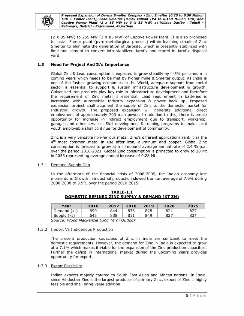
1.3.1 Demand-Supply Gap
In the aftermath of the financial crisis of 2008
momentum. Growth in industrial
2000-2008 to 3.9% over the period 2010
DOMESTIC REFINED
Year 2016
Demand (kt) 699
Supply (kt) 643
Source: Wood Mackenzie Long Term Outlook
1.3.2 Import Vs Indigenous Production
The present production capacities of
domestic requirements. However, the demand for
at a 7.1% which makes it viable for the expansion of the
Further the deficit in international market during the upcoming years provides
opportunity for export.
1.3.3 Export Possibility
Indian exports majorly catered to South East Asian and African nations. In India,
since Hindustan Zinc is the largest producer of primary
feasible and shall bring value addition.
Proposed Expansion of Dariba Smelter Complex - Zinc Smelter (0.25 to 0.50 Million TPA + Fumer Plant), Lead Smelter (0.125 Million TPA to 0.150 Million TPA) and Captive Power Plant (2 x 85 MW to 3 X 85 MW) at Village Dariba ,
Rajsamand, Rajasthan
MW (3 X 85 MW) of Captive Power Plant. It is also proposed
Fumer plant (pyro metallurgical process) within leaching circuit of
to eliminate the generation of Jarosite, which is presently stabilized with
lime and cement to convert into stabilized Jarofix and stored in Jarofix disposal
or Project And It’s Importance
consumption is expected to grow steadily by 4-5% per annum in
coming years which needs to be met by higher mine & Smelter output. As India is one of the fastest growing economies in the World, adequate support from metal
sector is essential to support & sustain infrastructure development & growth.
Galvanized iron products play key role in infrastructure development and therefore
Zinc metal is essential. Lead requirement in batteries is
increasing with Automobile Industry expansion & power back up. Proposed
expansion project shall augment the supply of Zinc to the domestic market for
Industrial growth. The proposed expansion will generate additional dir
employment of approximately 700 man power. In addition to this, there is ample
tunity for increase in indirect employment due to transport, workshop,
garages and other services. Skill development & training programs to make local
youth employable shall continue for development of community.
is a very versatile non-ferrous metal. Zinc’s different applications rank it as the
most common metal in use after iron, aluminum and copper.
consumption is forecast to grow at a compound average annual rate of 2.4 % p.a.
2021. Global Zinc consumption is projected to grow to 20 Mt
in 2035 representing average annual increase of 0.28 Mt.
In the aftermath of the financial crisis of 2008-2009, the Indian economy lost
momentum. Growth in industrial production slowed from an average of 7.9% during
2008 to 3.9% over the period 2010-2015.
TABLE-1.1
DOMESTIC REFINED ZINC SUPPLY & DEMAND (KT ZN)
2016 2017 2018 2019 2020
699 844 833 828 824
643 838 811 849 837
Source: Wood Mackenzie Long Term Outlook
Import Vs Indigenous Production
The present production capacities of Zinc in India are sufficient to meet the
domestic requirements. However, the demand for Zinc in India is expected to grow
at a 7.1% which makes it viable for the expansion of the Zinc production capacities.
Further the deficit in international market during the upcoming years provides
Indian exports majorly catered to South East Asian and African nations. In India,
is the largest producer of primary Zinc, export of
feasible and shall bring value addition.
Zinc Smelter (0.25 to 0.50 Million TPA + Fumer Plant), Lead Smelter (0.125 Million TPA to 0.150 Million TPA) and Captive Power Plant (2 x 85 MW to 3 X 85 MW) at Village Dariba , Tehsil -
5 | P a g e
It is also proposed
Fumer plant (pyro metallurgical process) within leaching circuit of Zinc
to eliminate the generation of Jarosite, which is presently stabilized with
lime and cement to convert into stabilized Jarofix and stored in Jarofix disposal
5% per annum in
output. As India is one of the fastest growing economies in the World, adequate support from metal
ustain infrastructure development & growth.
Galvanized iron products play key role in infrastructure development and therefore
requirement in batteries is
r back up. Proposed
to the domestic market for
Industrial growth. The proposed expansion will generate additional direct
power. In addition to this, there is ample
tunity for increase in indirect employment due to transport, workshop,
garages and other services. Skill development & training programs to make local
’s different applications rank it as the
most common metal in use after iron, aluminum and copper. Global Zinc
consumption is forecast to grow at a compound average annual rate of 2.4 % p.a.
consumption is projected to grow to 20 Mt
2009, the Indian economy lost
production slowed from an average of 7.9% during
2025
827
837
in India are sufficient to meet the
in India is expected to grow
production capacities.
Further the deficit in international market during the upcoming years provides
Indian exports majorly catered to South East Asian and African nations. In India,
, export of Zinc is highly

Proposed Expansion of Dariba Smelter Complex TPA + Fumer Plant), Lead Smelter (0.125 Million TPA to 0.150 Million TPA) and Captive Power Plant (2 x 85 MW to 3 X 85 MW) at Village Dariba , Relmagra, District - R
1.3.4 Domestic/Export Market
Zinc having found primary application in galvanization, a range of galvanized
products are produced to meet various Industrial an
Galvanized sheets (corrugated and plain), galvanized pipes, galvanized structure,
galvanized sheet, galvanized
Segment accounts for 68% share of the overall
Galvanizing accounts for 32% share. Among the major customer segments,
Galvanized Sheets accounts for major share of the
structure and Alloys. The following chart explains the demand for its segment wise break-
global Zinc demand continues to be high & driven mainly by galvan
the emerging of Asia and Africa. The reported increase in Chinese manufacturing
activities and US automotive sales along with emerging signs of stability in Europe’s
manufacturing and services sector are expected to support
Proposed Expansion of Dariba Smelter Complex - Zinc Smelter (0.25 to 0.50 Million TPA + Fumer Plant), Lead Smelter (0.125 Million TPA to 0.150 Million TPA) and Captive Power Plant (2 x 85 MW to 3 X 85 MW) at Village Dariba ,
Rajsamand, Rajasthan
Domestic/Export Market
having found primary application in galvanization, a range of galvanized
products are produced to meet various Industrial and consumer demands.
sheets (corrugated and plain), galvanized pipes, galvanized structure,
galvanized sheet, galvanized wires are used for various applications. Galvanizing
Segment accounts for 68% share of the overall Zinc demand in India while Non
Galvanizing accounts for 32% share. Among the major customer segments,
Galvanized Sheets accounts for major share of the Zinc consumption followed by
structure and Alloys. The following chart explains the demand for Zinc-up India has the potential for exporting Zinc
demand continues to be high & driven mainly by galvanizing sector in
the emerging of Asia and Africa. The reported increase in Chinese manufacturing
activities and US automotive sales along with emerging signs of stability in Europe’s
manufacturing and services sector are expected to support Zinc demand.
Zinc Smelter (0.25 to 0.50 Million TPA + Fumer Plant), Lead Smelter (0.125 Million TPA to 0.150 Million TPA) and Captive Power Plant (2 x 85 MW to 3 X 85 MW) at Village Dariba , Tehsil -
6 | P a g e
having found primary application in galvanization, a range of galvanized
d consumer demands.
sheets (corrugated and plain), galvanized pipes, galvanized structure,
wires are used for various applications. Galvanizing
demand in India while Non-
Galvanizing accounts for 32% share. Among the major customer segments,
consumption followed by
Zinc in India and profitably as
izing sector in
the emerging of Asia and Africa. The reported increase in Chinese manufacturing
activities and US automotive sales along with emerging signs of stability in Europe’s
demand.
Proposed Expansion of Dariba Smelter Complex TPA + Fumer Plant), Lead Smelter (0.125 Million TPA to 0.150 Million TPA) and Captive Power Plant (2 x 85 MW to 3 X 85 MW) at Village Dariba , Relmagra, District - R
1.4 Legal Aspects
The relevant NOC’s and licenses will be obtained from the statutory agencies
under the following Acts, Rules and amendments and HZ
guidelines specified in:
• The Factories Act, 1948
• Environment (Protection)
• Manufacture, Storage and Import of Hazardous Chemical Rules 1989 amended
in 2010; • The Hazardous Waste (Management and
HZL will comply with the prescribed limits laid down for air, effluent and n
emissions for protection of the environment under the following Acts, Rules and
amendments:
• The Water (Prevention and Control of Pollution) Act, 1974
• The Air (Prevention and Control of Pollution) Act, 1981
• The Environment (Protection) Act, 1986
• The Environment Impact Assessment, Notification, 2006
under; • Environment (Protection) Act 1986 and Environment (Protection) Rules 1986
and amendments thereafter to date.
Compliance to State Rules and Notifications will also be ensured
Proposed Expansion of Dariba Smelter Complex - Zinc Smelter (0.25 to 0.50 Million TPA + Fumer Plant), Lead Smelter (0.125 Million TPA to 0.150 Million TPA) and Captive Power Plant (2 x 85 MW to 3 X 85 MW) at Village Dariba ,
Rajsamand, Rajasthan
The relevant NOC’s and licenses will be obtained from the statutory agencies
cts, Rules and amendments and HZL will adhere to the
The Factories Act, 1948;
Environment (Protection) Act – 1986 and its amendments to date;
Manufacture, Storage and Import of Hazardous Chemical Rules 1989 amended
The Hazardous Waste (Management and Handling) Rules 1989.
L will comply with the prescribed limits laid down for air, effluent and n
emissions for protection of the environment under the following Acts, Rules and
The Water (Prevention and Control of Pollution) Act, 1974;
The Air (Prevention and Control of Pollution) Act, 1981;
The Environment (Protection) Act, 1986;
he Environment Impact Assessment, Notification, 2006 Rules issued
Environment (Protection) Act 1986 and Environment (Protection) Rules 1986
and amendments thereafter to date.
Compliance to State Rules and Notifications will also be ensured.
Zinc Smelter (0.25 to 0.50 Million TPA + Fumer Plant), Lead Smelter (0.125 Million TPA to 0.150 Million TPA) and Captive Power Plant (2 x 85 MW to 3 X 85 MW) at Village Dariba , Tehsil -
7 | P a g e
The relevant NOC’s and licenses will be obtained from the statutory agencies
L will adhere to the
;
Manufacture, Storage and Import of Hazardous Chemical Rules 1989 amended
L will comply with the prescribed limits laid down for air, effluent and noise
emissions for protection of the environment under the following Acts, Rules and
issued there
Environment (Protection) Act 1986 and Environment (Protection) Rules 1986

Proposed Expansion of Dariba Smelter Complex TPA + Fumer Plant), Lead Smelter (0.125 Million TPA to 0.150 Million TPA) and Captive Power Plant (2 x 85 MW to 3 X 85 MW) at Village Dariba , Relmagra, District - R
PROJECT DESCRIPTION
Proposed Expansion of Dariba Smelter Complex - Zinc Smelter (0.25 to 0.50 Million TPA + Fumer Plant), Lead Smelter (0.125 Million TPA to 0.150 Million TPA) and Captive Power Plant (2 x 85 MW to 3 X 85 MW) at Village Dariba ,
Rajsamand, Rajasthan
CHAPTER
PROJECT DESCRIPTION
Zinc Smelter (0.25 to 0.50 Million TPA + Fumer Plant), Lead Smelter (0.125 Million TPA to 0.150 Million TPA) and Captive Power Plant (2 x 85 MW to 3 X 85 MW) at Village Dariba , Tehsil -
8 | P a g e
CHAPTER-2
PROJECT DESCRIPTION

Proposed Expansion of Dariba Smelter Complex TPA + Fumer Plant), Lead Smelter (0.125 Million TPA to 0.150 Million TPA) and Captive Power Plant (2 x 85 MW to 3 X 85 MW) at Village Dariba , Relmagra, District - R
2.1 Project Description
I. Type of Project including interlinked
This chapter describes the process, and sources of pollution
i.e. production of Zinc from 2,50,000 TPA to
TPA to 1,50,000 TPA and power generation from 170
MW to meet the needs of Dariba
The following were the principle objectives, kept in mind while working on t
feasibility of this proposal.
• Adopting environment friendly technology & e
reduction of pollution load
fumer plant.
• Conserving natural resources like water, t
• Waste reduction and recycling options
• Aiming at waste heat recovery to best possible extent by state of art proven
technology
• Value added By- Products
The proposed expansion project is
Ministry of Environment & Forest
September 2006.
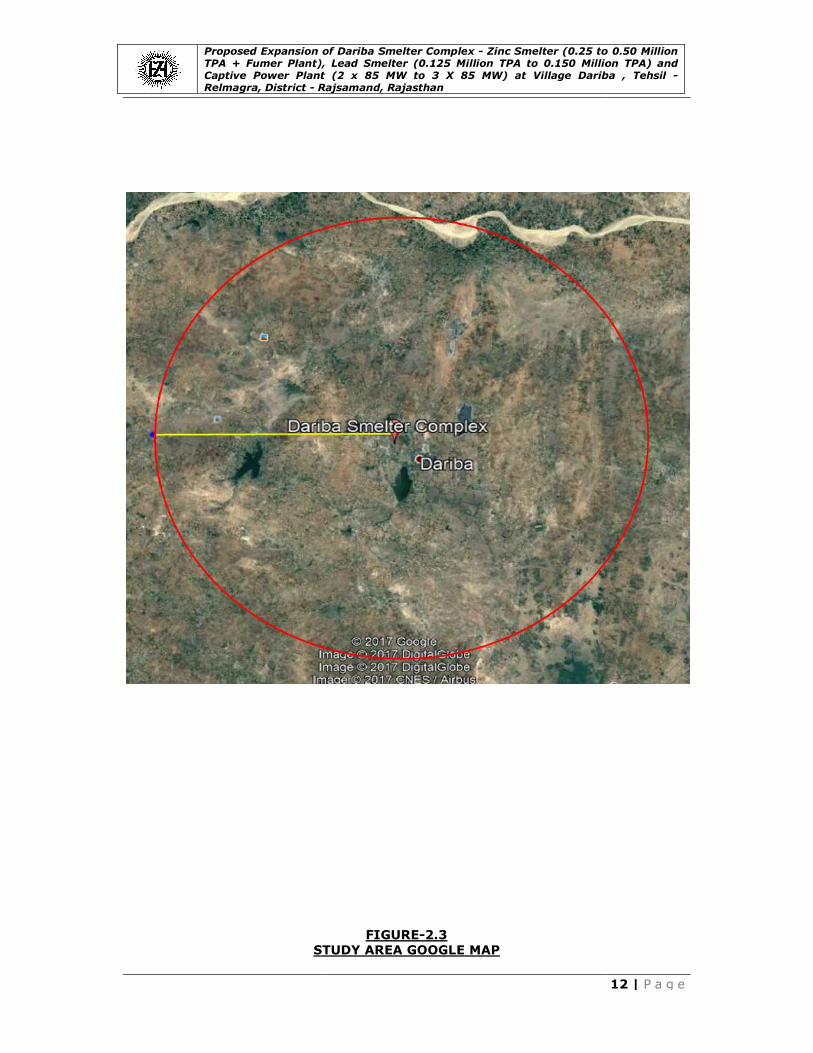
II. Location (map showing general location, specific location, and project
boundary& project site layout) with
Dariba Smelter Complex is located at a distance of 76 km NNE of Udaipur. The
nearest railway station is Fatehnagar, about 15.5
gauge railway line.The Plant
Chittorgarh, Bhilwara and District of India Toposheet No. 45/L1.
map and study area satellite map
2.2 and Figure-2.3.Environmental Setting of the Site
Proposed Expansion of Dariba Smelter Complex - Zinc Smelter (0.25 to 0.50 Million TPA + Fumer Plant), Lead Smelter (0.125 Million TPA to 0.150 Million TPA) and Captive Power Plant (2 x 85 MW to 3 X 85 MW) at Village Dariba ,
Rajsamand, Rajasthan
I. Type of Project including interlinked and independent projects
chapter describes the process, and sources of pollution for proposed
from 2,50,000 TPA to 5,00,000 TPA, Lead from 1,25,000
and power generation from 170 (2 X 85) MW to 255
to meet the needs of Dariba Smelter Complex, in the existing premises.
were the principle objectives, kept in mind while working on t
feasibility of this proposal.
ironment friendly technology & equipment and working on
reduction of pollution load of hazardous solid waste i.e. Jarosite
natural resources like water, thermal & electrical energy.
reduction and recycling options
Aiming at waste heat recovery to best possible extent by state of art proven
Products
The proposed expansion project is classified as “CATEGORY-3(a) & 1(d)
inistry of Environment & Forest, New Delhi as per the EIA Notification d
II. Location (map showing general location, specific location, and project
boundary& project site layout) with coordinates:
is located at a distance of 76 km NNE of Udaipur. The
station is Fatehnagar, about 15.5 km on Chittorgarh-Udaipur
The Plant is well connected by a metalled road from Udaipur,
ilwara and District headquarter Rajsamand. The plant falls in Surveof India Toposheet No. 45/L1. Geographical location of the project site, study area
map and study area satellite map have been provided in the Figure-2
Environmental Setting of the Site is provided in the
Zinc Smelter (0.25 to 0.50 Million TPA + Fumer Plant), Lead Smelter (0.125 Million TPA to 0.150 Million TPA) and Captive Power Plant (2 x 85 MW to 3 X 85 MW) at Village Dariba , Tehsil -
9 | P a g e
and independent projects
proposed expansion
from 1,25,000
85) MW to 255 (3 X 85)
, in the existing premises.
were the principle objectives, kept in mind while working on the
quipment and working on
of hazardous solid waste i.e. Jarosite by setting
hermal & electrical energy.
Aiming at waste heat recovery to best possible extent by state of art proven
3(a) & 1(d)” by
the EIA Notification dated14th
II. Location (map showing general location, specific location, and project
is located at a distance of 76 km NNE of Udaipur. The
Udaipur broad
is well connected by a metalled road from Udaipur,
falls in Survey site, study area
2.1, Figure-
is provided in the Table 2.1.

Proposed Expansion of Dariba Smelter Complex TPA + Fumer Plant), Lead Smelter (0.125 Million TPA to 0.150 Million TPA) and Captive Power Plant (2 x 85 MW to 3 X 85 MW) at Village Dariba , Relmagra, District - R
GEOGRAPHICAL LOCATION OF THE PROJECT
Proposed Expansion of Dariba Smelter Complex - Zinc Smelter (0.25 to 0.50 Million TPA + Fumer Plant), Lead Smelter (0.125 Million TPA to 0.150 Million TPA) and Captive Power Plant (2 x 85 MW to 3 X 85 MW) at Village Dariba ,
Rajsamand, Rajasthan
FIGURE-2.1
GEOGRAPHICAL LOCATION OF THE PROJECT
Rajasthan
Dariba Smelter Complex
Zinc Smelter (0.25 to 0.50 Million TPA + Fumer Plant), Lead Smelter (0.125 Million TPA to 0.150 Million TPA) and Captive Power Plant (2 x 85 MW to 3 X 85 MW) at Village Dariba , Tehsil -
10 | P a g e
Dariba Smelter Complex

Proposed Expansion of Dariba Smelter Complex TPA + Fumer Plant), Lead Smelter (0.125 Million TPA to 0.150 Million TPA) and Captive Power Plant (2 x 85 MW to 3 X 85 MW) at Village Dariba , Relmagra, District - R
Proposed Expansion of Dariba Smelter Complex - Zinc Smelter (0.25 to 0.50 Million TPA + Fumer Plant), Lead Smelter (0.125 Million TPA to 0.150 Million TPA) and Captive Power Plant (2 x 85 MW to 3 X 85 MW) at Village Dariba ,
Rajsamand, Rajasthan
FIGURE-2.2
STUDY AREA MAP
Zinc Smelter (0.25 to 0.50 Million TPA + Fumer Plant), Lead Smelter (0.125 Million TPA to 0.150 Million TPA) and Captive Power Plant (2 x 85 MW to 3 X 85 MW) at Village Dariba , Tehsil -
11 | P a g e
Proposed Expansion of Dariba Smelter Complex TPA + Fumer Plant), Lead Smelter (0.125 Million TPA to 0.150 Million TPA) and Captive Power Plant (2 x 85 MW to 3 X 85 MW) at Village Dariba , Relmagra, District - R
STUDY AREA
Proposed Expansion of Dariba Smelter Complex - Zinc Smelter (0.25 to 0.50 Million TPA + Fumer Plant), Lead Smelter (0.125 Million TPA to 0.150 Million TPA) and Captive Power Plant (2 x 85 MW to 3 X 85 MW) at Village Dariba ,
Rajsamand, Rajasthan
FIGURE-2.3
STUDY AREA GOOGLE MAP
Zinc Smelter (0.25 to 0.50 Million TPA + Fumer Plant), Lead Smelter (0.125 Million TPA to 0.150 Million TPA) and Captive Power Plant (2 x 85 MW to 3 X 85 MW) at Village Dariba , Tehsil -
12 | P a g e
Proposed Expansion of Dariba Smelter Complex TPA + Fumer Plant), Lead Smelter (0.125 Million TPA to 0.150 Million TPA) and Captive Power Plant (2 x 85 MW to 3 X 85 MW) at Village Dariba , Relmagra, District - R
ENVIRONMENTAL SETTING OF THE SITE
Sr. No. Particulars
1. Project Location
2. Latitude
3. Longitude
4. Elevation above MSL
5. Toposheet No.
6. Climatic conditions
IMD Dabok (Udaipur)
7. Nearest Highway
8. Nearest Railway Station
9. Nearest Airport
10. Nearest River
11. Nearest Port
12. Nearest Village
13. Nearest Town/City
14. Hills/Valleys
15. Monuments
16. Archaeologically important
places
17. Reserved/Protected forest
18. Protected areas as per Wildlife
Protection Act, 1972
(Biospheres, Tiger Reserves,
Elephant Reserves, National
Parks, Wildlife Sanctuaries,
Conservation Reserves, and Community Reserves)
19. List of Industries
20. Seismicity
Proposed Expansion of Dariba Smelter Complex - Zinc Smelter (0.25 to 0.50 Million TPA + Fumer Plant), Lead Smelter (0.125 Million TPA to 0.150 Million TPA) and Captive Power Plant (2 x 85 MW to 3 X 85 MW) at Village Dariba ,
Rajsamand, Rajasthan
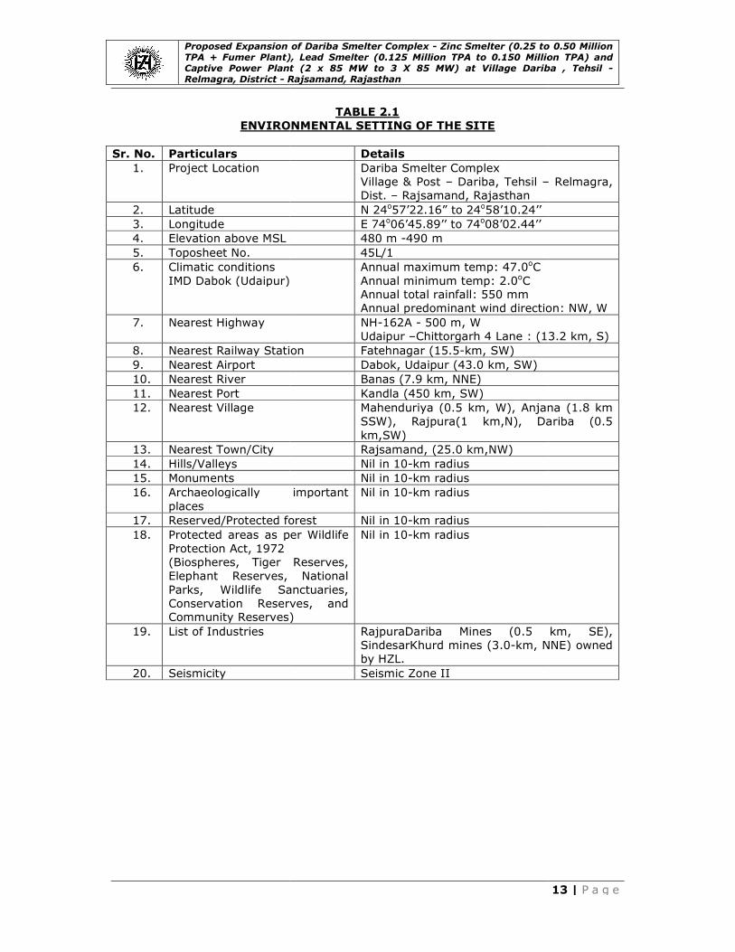
TABLE 2.1
ENVIRONMENTAL SETTING OF THE SITE
Details
Dariba Smelter Complex
Village & Post – Dariba, Tehsil –
Dist. – Rajsamand, Rajasthan
N 24o57’22.16” to 24o58’10.24’’
E 74o06’45.89’’ to 74o08’02.44’’
480 m -490 m
45L/1
(Udaipur)
Annual maximum temp: 47.0oC
Annual minimum temp: 2.0oC Annual total rainfall: 550 mm
Annual predominant wind direction: NW, W
NH-162A - 500 m, W
Udaipur –Chittorgarh 4 Lane : (13.2
Nearest Railway Station Fatehnagar (15.5-km, SW)
Dabok, Udaipur (43.0 km, SW)
Banas (7.9 km, NNE)
Kandla (450 km, SW)
Mahenduriya (0.5 km, W), Anjana (
SSW), Rajpura(1 km,N), Dariba (0.5
km,SW)
Rajsamand, (25.0 km,NW)
Nil in 10-km radius
Nil in 10-km radius
Archaeologically important Nil in 10-km radius
Reserved/Protected forest Nil in 10-km radius
Protected areas as per Wildlife
(Biospheres, Tiger Reserves,
Elephant Reserves, National
Parks, Wildlife Sanctuaries,
Conservation Reserves, and Community Reserves)
Nil in 10-km radius
RajpuraDariba Mines (0.5
SindesarKhurd mines (3.0-km, NNE) owned
by HZL.
Seismic Zone II
Zinc Smelter (0.25 to 0.50 Million TPA + Fumer Plant), Lead Smelter (0.125 Million TPA to 0.150 Million TPA) and Captive Power Plant (2 x 85 MW to 3 X 85 MW) at Village Dariba , Tehsil -
13 | P a g e
– Relmagra,
Annual predominant wind direction: NW, W
13.2 km, S)
Anjana (1.8 km
, Dariba (0.5
Dariba Mines (0.5 km, SE),
km, NNE) owned

Proposed Expansion of Dariba Smelter Complex TPA + Fumer Plant), Lead Smelter (0.125 Million TPA to 0.150 Million TPA) and Captive Power Plant (2 x 85 MW to 3 X 85 MW) at Village Dariba , Relmagra, District - R
Zinc Smelter
Considering various process options available such as Pyro
route & Hydrometallurgical route, HZL
at Dariba using conventional hydro
winning operations for the following reasons:
1. Higher recovery of
2. Production of Special high grade quality
Also, there is no plant operating in the world following pyro
for more than 0.12 MTPA.
Conventional hydro-metallurgical route for
Leach- Electro-winning” operations. The raw material for the
concentrate, which contains about 50
Zinc concentrate containing
Zinc oxide, which is leached in dilute sulphuric acid to produce a raw
sulphate solution. The impurities like copper, cadmium, nickel, cobalt etc also get
dissolved in the solution as sulphates.
thickeners & clear over flowactivators. The purified
cathodes, which are then melted and cast into
obtained during purification are sent to cadmium section.
from leaching is Jarosite, a waste which is being stabilized by addition of lime and
cement. The product is called Jarofix which is stockpiled at Jarofix yard and needs
recurring land.
To eliminate Jarosite generation, it is proposed to set up fuming process within
existing leaching circuit of
Salient Features
• Recovery of minor metals like reduction in waste generation
• Efficient gas cooling and cleaning pro
• Double Conversion Double Absorption (DCDA) process with Cesium catalyst
results in high SO2 recovery (>99.8 %) and low SO
• Thermally auto genous process with power generat
• High end automation and interlocking with pollution control equipments
• Pneumatic conveying system for calcine tanker unloading
• Online stack monitoring for SO
Fumer Plant
After modification, the current jarosite process will be converted to the
conventional leaching process, from which
will be treated with fuming furnaces.
In the fuming process, the leaching residue is treated in stages
furnace. The stages are: residue melting and heating, fuming, and slag tapping.
To reduce energy consumption and to facilitate leaching residue transfer after
filtration, the residue will be dried by drying kiln.
system consists of leaching residue drying,
heat recovery and dust collection
Proposed Expansion of Dariba Smelter Complex - Zinc Smelter (0.25 to 0.50 Million TPA + Fumer Plant), Lead Smelter (0.125 Million TPA to 0.150 Million TPA) and Captive Power Plant (2 x 85 MW to 3 X 85 MW) at Village Dariba ,
Rajsamand, Rajasthan
Considering various process options available such as Pyro-metallurgical ISF
route & Hydrometallurgical route, HZL has installed a hydrometallurgical
at Dariba using conventional hydro-metallurgical route of roast-leach
winning operations for the following reasons:
Higher recovery of Zinc and other by-products
Production of Special high grade quality Zinc (SHG)
Also, there is no plant operating in the world following pyro-metallurgical route
for more than 0.12 MTPA.
metallurgical route for Zinc extraction is through “Roast
winning” operations. The raw material for the Zinc Smel
which contains about 50% Zinc in the form of Zinc Sulphide
concentrate containing Zinc& other impurities is roasted to convert it into
oxide, which is leached in dilute sulphuric acid to produce a raw
sulphate solution. The impurities like copper, cadmium, nickel, cobalt etc also get
dissolved in the solution as sulphates. The insoluble impurities are separated in
thickeners & clear over flowis purified by addition of Zinc dust / powder and The purified Zinc sulphate solution is then electrolysed to obtain
cathodes, which are then melted and cast into Zinc metal ingots. The filter cakes
obtained during purification are sent to cadmium section. Iron residue generated
site, a waste which is being stabilized by addition of lime and
called Jarofix which is stockpiled at Jarofix yard and needs
To eliminate Jarosite generation, it is proposed to set up fuming process within
existing leaching circuit of Zinc Smelter.
Recovery of minor metals like Lead-Silver, Copper and Cadmium therebreduction in waste generation;
gas cooling and cleaning process to get optically clear gas
Double Conversion Double Absorption (DCDA) process with Cesium catalyst
recovery (>99.8 %) and low SO2 emission in acid plant
genous process with power generation from waste heat
High end automation and interlocking with pollution control equipments
Pneumatic conveying system for calcine tanker unloading;
Online stack monitoring for SOx.
After modification, the current jarosite process will be converted to the
conventional leaching process, from which 3,80,000 tons of residue (dry base)
will be treated with fuming furnaces.
In the fuming process, the leaching residue is treated in stages
furnace. The stages are: residue melting and heating, fuming, and slag tapping.
To reduce energy consumption and to facilitate leaching residue transfer after
filtration, the residue will be dried by drying kiln. The leaching residue treatment
system consists of leaching residue drying, proportioning, fuming, off gas waste
heat recovery and dust collection .Off gas from the drying kiln and the fuming
Zinc Smelter (0.25 to 0.50 Million TPA + Fumer Plant), Lead Smelter (0.125 Million TPA to 0.150 Million TPA) and Captive Power Plant (2 x 85 MW to 3 X 85 MW) at Village Dariba , Tehsil -
14 | P a g e
metallurgical ISF
a hydrometallurgical Smelter
leach-electro-
metallurgical route
extraction is through “Roast-
Smelter is Zinc
Sulphide. The
& other impurities is roasted to convert it into
oxide, which is leached in dilute sulphuric acid to produce a raw Zinc
sulphate solution. The impurities like copper, cadmium, nickel, cobalt etc also get
The insoluble impurities are separated in
dust / powder and sulphate solution is then electrolysed to obtain Zinc
metal ingots. The filter cakes
Iron residue generated
site, a waste which is being stabilized by addition of lime and
called Jarofix which is stockpiled at Jarofix yard and needs
To eliminate Jarosite generation, it is proposed to set up fuming process within
Silver, Copper and Cadmium thereby
cess to get optically clear gas;
Double Conversion Double Absorption (DCDA) process with Cesium catalyst
emission in acid plant;
ion from waste heat;
High end automation and interlocking with pollution control equipments;
After modification, the current jarosite process will be converted to the
tons of residue (dry base)
In the fuming process, the leaching residue is treated in stages in a fuming
furnace. The stages are: residue melting and heating, fuming, and slag tapping.
To reduce energy consumption and to facilitate leaching residue transfer after
The leaching residue treatment
proportioning, fuming, off gas waste
.Off gas from the drying kiln and the fuming

Proposed Expansion of Dariba Smelter Complex TPA + Fumer Plant), Lead Smelter (0.125 Million TPA to 0.150 Million TPA) and Captive Power Plant (2 x 85 MW to 3 X 85 MW) at Village Dariba , Relmagra, District - R
furnaces will be sent to the off gas
desulfurization technology will be used,
produced from the fuming off gas and dust.
Salient Features
• The fuming slag is the clean slag;
• Valuable metals such as Zn, Pb, Ag will be extracted from the leaching
at high recovery rates;
• The fuming off gas will be de• The off gas waste heat will be recovered in steam for power generation, which
will serve the plant and save energy;
• In the material handling system, the
granulation area will be equipped with ventilation and dust removal facilities,
which improve the working environment;
• The two fuming furnaces will run in
flexibility; However if required one can also be operated in case of exigencies
• The furnace tuyeres have a long service life;
• The furnace is easy to operate and highly automatic.
Lead Smelter
Based on HZL’s prior experience and recent assessment of technology the
following process technology options were evaluated.
• Ausmelt Technology (Single Furnace Philosophy)
• Ausmelt Technology (Twin furnace philosophy)
• SKS Technology – China
Based on the evaluations done, SKS Technology route has been selected for the
following reasons:
• ENFI / NFC technology offer is including minor
facilities like Cu, Sb , Bi , Ag etc
• ENFI / NFC china offering a total turnkey solution from Technology to EPC
process Guarantees
Salient Features
• Pyro-route for smelting & hydro
• High Lead, Zinc and Silver Recovery
• Recovery of minor metals
• Process capability to accept
Smelter) and other Lead
• Effective dust collection and Hygiene systems
• Online stack monitoring for SOx
Captive Power Plant
Based on our proven and
steam turbine generator has been selected
Proposed Expansion of Dariba Smelter Complex - Zinc Smelter (0.25 to 0.50 Million TPA + Fumer Plant), Lead Smelter (0.125 Million TPA to 0.150 Million TPA) and Captive Power Plant (2 x 85 MW to 3 X 85 MW) at Village Dariba ,
Rajsamand, Rajasthan
furnaces will be sent to the off gas desulfurization plant (TGP).
desulfurization technology will be used, and the Zinc oxide needed will be
produced from the fuming off gas and dust.
The fuming slag is the clean slag;
Valuable metals such as Zn, Pb, Ag will be extracted from the leaching
at high recovery rates;
The fuming off gas will be de sulfurized to meet environmental requirements;The off gas waste heat will be recovered in steam for power generation, which
will serve the plant and save energy;
In the material handling system, the discharge points, slag tap holes, and the
granulation area will be equipped with ventilation and dust removal facilities,
which improve the working environment;
The two fuming furnaces will run in series, a pattern which provides high
However if required one can also be operated in case of exigencies
The furnace tuyeres have a long service life;
The furnace is easy to operate and highly automatic.
Based on HZL’s prior experience and recent assessment of technology the
following process technology options were evaluated.
Ausmelt Technology (Single Furnace Philosophy) - Australia
Ausmelt Technology (Twin furnace philosophy) - Australia
China
Based on the evaluations done, SKS Technology route has been selected for the
ENFI / NFC technology offer is including minor metal & precious metal recovery
facilities like Cu, Sb , Bi , Ag etc
ENFI / NFC china offering a total turnkey solution from Technology to EPC
route for smelting & hydro-route for Lead refining
and Silver Recovery
Recovery of minor metals- Silver, Copper, Antimony and Bismuth
Process capability to accept Lead Silver compound (a by-product of
Lead Secondary
Effective dust collection and Hygiene systems
Online stack monitoring for SOx
Based on our proven and satisfactory experience, pulverised coal fired Boiler with
steam turbine generator has been selected.
Zinc Smelter (0.25 to 0.50 Million TPA + Fumer Plant), Lead Smelter (0.125 Million TPA to 0.150 Million TPA) and Captive Power Plant (2 x 85 MW to 3 X 85 MW) at Village Dariba , Tehsil -
15 | P a g e
desulfurization plant (TGP). Zinc oxide
oxide needed will be
Valuable metals such as Zn, Pb, Ag will be extracted from the leaching residue
sulfurized to meet environmental requirements; The off gas waste heat will be recovered in steam for power generation, which
discharge points, slag tap holes, and the
granulation area will be equipped with ventilation and dust removal facilities,
, a pattern which provides high
However if required one can also be operated in case of exigencies
Based on HZL’s prior experience and recent assessment of technology the
Based on the evaluations done, SKS Technology route has been selected for the
metal & precious metal recovery
ENFI / NFC china offering a total turnkey solution from Technology to EPC to
Antimony and Bismuth
product of Zinc
satisfactory experience, pulverised coal fired Boiler with

Proposed Expansion of Dariba Smelter Complex TPA + Fumer Plant), Lead Smelter (0.125 Million TPA to 0.150 Million TPA) and Captive Power Plant (2 x 85 MW to 3 X 85 MW) at Village Dariba , Relmagra, District - R
Salient Features
• High efficiency ESPs with 8 nos. of fields
• Covered coal conveyors with water sprinkling system using waste water
• Bag filters at each coal transfer point, coal bunkers and fly ash silos to restrict
emission;
• SOx and D Nox systems such as FGD and SCR for meeting the latest
environmental norms
• Online stack monitoring for SOx, NOx and PM
Salient Features of the
• Integrated Utility plant
• Integrated Effluent treatment plant followed with two stage RO Plant
Multiple Effect Evaporator (MEE) Plant
• RO based DM plant thereby reducing effluent generation
• Transportation of raw material and finished products in 40 MT
• Cement concrete internal roads;
• Industrial sweeper;
• Truck / Tyre wash stations
2.2 Project Details
The Operational hydro-metallurgical
of Special High Grade
metallurgical route based on Roast
accepted process for manufacturing
Zinc production from 0.25 million TPA to 0.5million
this increase in production will take place in two phases, first from 0.25 to 0.375
million TPA then after successful commissioning 0.375 million TPA then the second
phase will start from 0.375 to 0.50 million TPA.
To eliminate the issue of Jwill stop producing Jarosite i.e. Hazardous waste and start producing Slag which is
non-hazardous waste. This important step is taken after inconsideration of
environmental concerns in whole world to reduce
environment for future generation i.e Sustainability
In this proposed expansion the
million TPA to 0.150 million TPA with same technology.
which is operational to meet the requirement of existing
due to rise in production of
meet the new requirements
Proposed Expansion of Dariba Smelter Complex - Zinc Smelter (0.25 to 0.50 Million TPA + Fumer Plant), Lead Smelter (0.125 Million TPA to 0.150 Million TPA) and Captive Power Plant (2 x 85 MW to 3 X 85 MW) at Village Dariba ,
Rajsamand, Rajasthan
High efficiency ESPs with 8 nos. of fields;
Covered coal conveyors with water sprinkling system using waste water
each coal transfer point, coal bunkers and fly ash silos to restrict
SOx and D Nox systems such as FGD and SCR for meeting the latest
environmental norms;
Online stack monitoring for SOx, NOx and PM.
Salient Features of the Smelters and CPP
Integrated Utility plant;
Integrated Effluent treatment plant followed with two stage RO Plant
Multiple Effect Evaporator (MEE) Plant;
RO based DM plant thereby reducing effluent generation;
Transportation of raw material and finished products in 40 MT bulkers
Cement concrete internal roads;
Truck / Tyre wash stations.
metallurgical Smelter is designed to produce 0.25 million
of Special High Grade Zinc annually from Zinc concentrate/Calcine. The hydro
metallurgical route based on Roast – Leach – Electro-winning process is widely
accepted process for manufacturing Zinc metal and it is proposed to increase the
production from 0.25 million TPA to 0.5million TPA with same technology.
this increase in production will take place in two phases, first from 0.25 to 0.375
fter successful commissioning 0.375 million TPA then the second
phase will start from 0.375 to 0.50 million TPA.
To eliminate the issue of Jarosite, the Fumer plant is proposed in this project rosite i.e. Hazardous waste and start producing Slag which is
waste. This important step is taken after inconsideration of
environmental concerns in whole world to reduce Hazardous waste for safer
environment for future generation i.e Sustainability.
In this proposed expansion the Lead Smelter production is increasing from 0.125
million TPA to 0.150 million TPA with same technology. There are 2 Plants of 85MW
rational to meet the requirement of existing Zinc Smelter
due to rise in production of Zinc there will be need of 1 more plant of 85
meet the new requirements Change in Plant Capacity is depicted in Table
Zinc Smelter (0.25 to 0.50 Million TPA + Fumer Plant), Lead Smelter (0.125 Million TPA to 0.150 Million TPA) and Captive Power Plant (2 x 85 MW to 3 X 85 MW) at Village Dariba , Tehsil -
16 | P a g e
Covered coal conveyors with water sprinkling system using waste water;
each coal transfer point, coal bunkers and fly ash silos to restrict
SOx and D Nox systems such as FGD and SCR for meeting the latest
Integrated Effluent treatment plant followed with two stage RO Plant and
bulkers;
is designed to produce 0.25 million TPA
cine. The hydro-
winning process is widely
and it is proposed to increase the
with same technology. But
this increase in production will take place in two phases, first from 0.25 to 0.375
fter successful commissioning 0.375 million TPA then the second
the Fumer plant is proposed in this project which rosite i.e. Hazardous waste and start producing Slag which is
waste. This important step is taken after inconsideration of
Hazardous waste for safer
production is increasing from 0.125
There are 2 Plants of 85MW
Complex but
there will be need of 1 more plant of 85 MW to
able-2.2.

Proposed Expansion of Dariba Smelter Complex TPA + Fumer Plant), Lead Smelter (0.125 Million TPA to 0.150 Million TPA) and Captive Power Plant (2 x 85 MW to 3 X 85 MW) at Village Dariba , Relmagra, District - R
Unit Existing Granted
Capacity (As per EC granted in
Nov.'2009)
ZincSmelter 0.5 MTPA
LeadSmelter 0.125 MTPA
Captive Power Plant
255 MW
Fumer Plant -
PRODUCTS AND BYPRODUCTS
Unit
Quantity (As per EC granted
in Nov.'2009)
Products
ZincSmelter
SHG Zinc Cathode/Ingot (Special High Grade)
Zinc (Continuous Galvanizing
Grade) (out of 500, 000 TPA SHG
Zinc)
LeadSmelter
Lead Cathode/Ingot
Lead Alloy (Pb-Sb&Pb-Ca, Pb-Bi) (out of 150, 000 TPA
Lead)
Captive Power Plant
Power
By-products (TPA)
Sulphuric Acid
Lead – Silver Compound
Cadmium metal / Sponge
(equivalent metal)
Calomel
Silver
Copper as Copper cement/
sulphate/ matte/ concentrate
/Compound(equivalent metal)
Antimony as Antimony
concentrate (equivalent metal)
Waste Heat power
Bismuth as Bismuth concentrate
(equivalent metal)
Zinc Oxide compound
Lead concentrate (Oxide)
Anode Slime
Lead Bullion
Proposed Expansion of Dariba Smelter Complex - Zinc Smelter (0.25 to 0.50 Million TPA + Fumer Plant), Lead Smelter (0.125 Million TPA to 0.150 Million TPA) and Captive Power Plant (2 x 85 MW to 3 X 85 MW) at Village Dariba ,
Rajsamand, Rajasthan
TABLE 2.2
PLANT CAPACITY
Existing Granted
Capacity (As per EC granted in
Existing
Status
Additional
Proposed Capacity
Total Capacities
AfterProposed
Expansion
0.25 MTPA 0.25 MTPA 0.5 MTPA
0.125 MTPA 0.025 MTPA 0.15
170 MW 85 MW 255
- Associated with
Zinc Smelter
Associated with
Smelter
TABLE-2.3
PRODUCTS AND BYPRODUCTS
Existing Granted
Quantity (As per EC granted
in Nov.'2009)
Existing Status Additional Proposed
Quantity
0.50 MTPA 0.25 MTPA 0.25 MTPA
0.08 MTPA 0.04 MTPA 0.04 MTPA
0.125 MTPA 0.125 MTPA 0.025 MTPA
0.05 MTPA 0.05 MTPA 0.01 MTPA
255 MW 170 MW 85 MW
744000 744000 90,000
80000 40000 40000
1600 800 1200
44 44 -
400 400 400
1900 1400 1400
850 850 170
15 MW 15 MW 20 MW
16 16 30
20000 20000 16000
5000 5000 1000
4000 4000 800
- - 20000
Zinc Smelter (0.25 to 0.50 Million TPA + Fumer Plant), Lead Smelter (0.125 Million TPA to 0.150 Million TPA) and Captive Power Plant (2 x 85 MW to 3 X 85 MW) at Village Dariba , Tehsil -
17 | P a g e
Total Capacities
After Proposed
Expansion
0.5 MTPA
0.15 MTPA
5 MW
Associated with Zinc
Smelter
Additional Proposed
Quantity
Total Quantity
After Proposed
Expansion
MTPA 0.50 MTPA
MTPA 0.08 MTPA
0.025 MTPA 0.150 MTPA
MTPA 0.06 MTPA
255 MW
8,34,000
80000
2000
No Change
800
2800
1020
35 MW
46
36000
6000
4800
20000

Proposed Expansion of Dariba Smelter Complex TPA + Fumer Plant), Lead Smelter (0.125 Million TPA to 0.150 Million TPA) and Captive Power Plant (2 x 85 MW to 3 X 85 MW) at Village Dariba , Relmagra, District - R
Raw Material Storage
The concentrate is unloaded at unloading station and stored in
storage yard, of 12,000 T capacity. From t
material into different hoppers. By means of discharge and transport belt
conveyors including an over
to a transfer tower, from where concentrate
Similarly, separate silos
Leaching & Purification area
The major raw materials for the pro
The raw materials requirement is given in
and mode of transportation is given in
through import. Other raw materials are
coal/coke for Lead Smelter
sourced from the market, based on techno
The requirement of other consumables (fuels &
plant has been estimated and furnished in
BASIC RAW MATERIAL
Raw Material
Quantity (As
granted in Nov.'2009)
Zinc concentrate
Calcine (ZnO)
Aluminium metal
Lead concentrate
Coal for LeadSmelter
Coke for LeadSmelter
Coal for Fumer Plant
Cu2SO4 for Fumer
plant
Coal for power plant 11
Lead Silver Compound
*
Zinc Dross/ Ash/ Zinc
bearing waste*
Battery/Lead Scrap and secondary *
BASIC RAW MATERIAL
Sr. No. Item
1 Zinc concentrate
2 Calcine (ZnO)
3 Aluminium metal
4 Lead concentrate
Proposed Expansion of Dariba Smelter Complex - Zinc Smelter (0.25 to 0.50 Million TPA + Fumer Plant), Lead Smelter (0.125 Million TPA to 0.150 Million TPA) and Captive Power Plant (2 x 85 MW to 3 X 85 MW) at Village Dariba ,
Rajsamand, Rajasthan
unloaded at unloading station and stored in
000 T capacity. From the stockyard, a pay loader
material into different hoppers. By means of discharge and transport belt
conveyors including an over-belt magnetic separator, the material is
to a transfer tower, from where concentrate is routed to the roasting plant.
separate silos for storing calcine have been made in the Roaster and
Leaching & Purification area.
The major raw materials for the project are Zinc concentrates, calcine and coal.
The raw materials requirement is given in Table-2.3. the raw material source
and mode of transportation is given in Table-2.4. Deficit, if any, shall be met
through import. Other raw materials are aluminum metal for CGG
Smelter and coal for power production. These materials will be
sourced from the market, based on techno-economic feasibility.
The requirement of other consumables (fuels & process chemicals) required in the
plant has been estimated and furnished in Table-2.5.
TABLE-2.3 BASIC RAW MATERIAL– SMELTERS & CPP
Existing
Granted
Quantity (As per EC
granted in Nov.'2009)
Existing
Requirement
Additional
Requirement
6,48,000 6,48,000 25000
2,80,000 - 2,80,000
160 80 80
2,60,000 2,60,000 90,000
26000 26,000 14,000
27000 27,000 11,000
- - 2,50,000
- - 600
11,62,000 7,74,667 3,87,333
80,000 40,000 40,000
- 30,000 -
80,000 80,000 -
TABLE-2.4
BASIC RAW MATERIAL– SOURCE & TRANSPORTATION
Total
Quantity/year
(Tonnes)
Source of supply
Imported% Indigenous%
concentrate 6,73,000 - 100
280,000 - 100
Aluminium metal 160 - 100
concentrate 3,50,000 45.3 54.7
Zinc Smelter (0.25 to 0.50 Million TPA + Fumer Plant), Lead Smelter (0.125 Million TPA to 0.150 Million TPA) and Captive Power Plant (2 x 85 MW to 3 X 85 MW) at Village Dariba , Tehsil -
18 | P a g e
unloaded at unloading station and stored in concentrate
he stockyard, a pay loader feed the
material into different hoppers. By means of discharge and transport belt
is transported
routed to the roasting plant.
in the Roaster and
concentrates, calcine and coal.
. the raw material source
. Deficit, if any, shall be met
metal for CGG Zinc and
and coal for power production. These materials will be
process chemicals) required in the
Total
Requirement
After Proposed
Expansion
6,73,000
2,80,000
160
3,50,000
40,000
38,000
2,50,000
600
11,62,000
80,000
30,000
80,000
Probable transportation
Imported India
- -
- -
- -
Kandla port HZL mines-

Proposed Expansion of Dariba Smelter Complex TPA + Fumer Plant), Lead Smelter (0.125 Million TPA to 0.150 Million TPA) and Captive Power Plant (2 x 85 MW to 3 X 85 MW) at Village Dariba , Relmagra, District - R
Sr. No. Item
5 Lead silver compound for
Lead
6 Lead secondary’s
7 Coal for Fumer
Plant
8 Coal for LeadSmelter
9 Coke for LeadSmelter
10 Coal for power
plant
CONSUMABLES PER ANNUM
Consumables
Flocculants
Lime
SiO2
H2FiS6 (Silico Fluoric Acid)
LDO/LSHS/HSD/LNG
Sulphuric acid (internal)
MnO2 (internal)
Caustic Soda Solution
Ammonium Chloride
Limestone
Iron Ore
Cement
Power Requirement
The power requirement for the
power requirement for the Captive Power Plant is envisaged for
Smelter.
Water Requirement
Water requirement for
kundia Dam, Mansi wakal Dam and Common Sewage Treatment Plant installed in
Udaipur. Consumption pattern of water for the enhancement of
is given in Table-2.6.
Proposed Expansion of Dariba Smelter Complex - Zinc Smelter (0.25 to 0.50 Million TPA + Fumer Plant), Lead Smelter (0.125 Million TPA to 0.150 Million TPA) and Captive Power Plant (2 x 85 MW to 3 X 85 MW) at Village Dariba ,
Rajsamand, Rajasthan
Total Quantity/year
(Tonnes)
Source of supply
Imported% Indigenous
%
silver compound for
80,000 - 100
secondary’s 80,000 50.0 50
Coal for Fumer 2,50,000 60.0 40
Coal for 40,000 60.0 40
Coke for 38,000 - 100
Coal for power 1,162,000 76.0 24
TABLE-2.5
CONSUMABLES PER ANNUM
Unit Quantity
Tons 266
Tons 68,500
Tons 13,000
(Silico Fluoric Acid) Tons 3,000
KL 14,00
Sulphuric acid (internal) Tons 27,500
Tons 6,375
M3 1,500
Tons 638
Tons 74,000
Tons 18,000
Tons 2,000
The power requirement for the Smelter and CPP project is 240 MW.
uirement for the Smelter, CPP will be 252 MW. 255 MW coal based Captive Power Plant is envisaged for providing power to proposed
Water requirement for industrial and township usage will be met from
wakal Dam and Common Sewage Treatment Plant installed in
Consumption pattern of water for the enhancement of Smelter
Zinc Smelter (0.25 to 0.50 Million TPA + Fumer Plant), Lead Smelter (0.125 Million TPA to 0.150 Million TPA) and Captive Power Plant (2 x 85 MW to 3 X 85 MW) at Village Dariba , Tehsil -
19 | P a g e
Probable transportation
Imported India
RAM, SK
mine,
Zawar
mines
- CLZS &DaribaSm
elter
complex
Kandla port Mumbai
Navlakhi,
Morbi near Mundra
Gotor,
Kanika, Rajarh
(MP)
Navlakhi, Morbi near
Mundra
Gotor, Kanika,
Rajarh (MP)
Mundra port
Gandhidham
Kandla port -
Quantity
266
500
000
000
000
500
375
500
638
,000
000
000
and CPP project is 240 MW. The total
will be 252 MW. 255 MW coal based providing power to proposed expansion
met from Matri
wakal Dam and Common Sewage Treatment Plant installed in
Smelters and CPP
Proposed Expansion of Dariba Smelter Complex TPA + Fumer Plant), Lead Smelter (0.125 Million TPA to 0.150 Million TPA) and Captive Power Plant (2 x 85 MW to 3 X 85 MW) at Village Dariba , Relmagra, District - R
Unit Existing Granted
Quantity (As per EC granted in
Nov.'2009)(m3/day)
Zinc Smelter 11,000
Fumer Plant -
Lead Smelter 7,250
Captive Power Plant
17,000
Domestic 1,000
Total 36,250
Water is sourced from the
Table-2.7
Source
Matri-kundia dam
Mansi Wakal dam
STP Udaipur
STP Udaipur – Expansion
Total
An agreement has been signed between the Govt. of Rajasthan and HZL for
supply of 117 mcft water from Matri
Understanding (MoU) has been signed between Govt. of Rajasthan and HZL for
implementation of Mansi
diverted from the Mansi
point of the common carrier system shall be made available to HZL.
2.3 Process Description
2.3.1 Zinc Smelter
• Roasting Plant
The Zinc concentrate, which is in
not leachable at normal temperature and acidity. It is therefore necessary to
convert this sulphide material to acid leachable form. The purpose of Roasting is to
convert the Zinc sulphide to
Roaster thereby expelling the sulphur as SOsulphuric acid in acid plant.
The Zinc concentrate to be treated is stored in a surge bin, with a holding
capacity for more than one shift.
The concentrate is discharged from the bin by means of a slow running rubber belt.
The capacity of Roaster furnace is 954 Tonnes of concentrate per day (Dry) with a
hearth area of 123 m2.
Proposed Expansion of Dariba Smelter Complex - Zinc Smelter (0.25 to 0.50 Million TPA + Fumer Plant), Lead Smelter (0.125 Million TPA to 0.150 Million TPA) and Captive Power Plant (2 x 85 MW to 3 X 85 MW) at Village Dariba ,
Rajsamand, Rajasthan
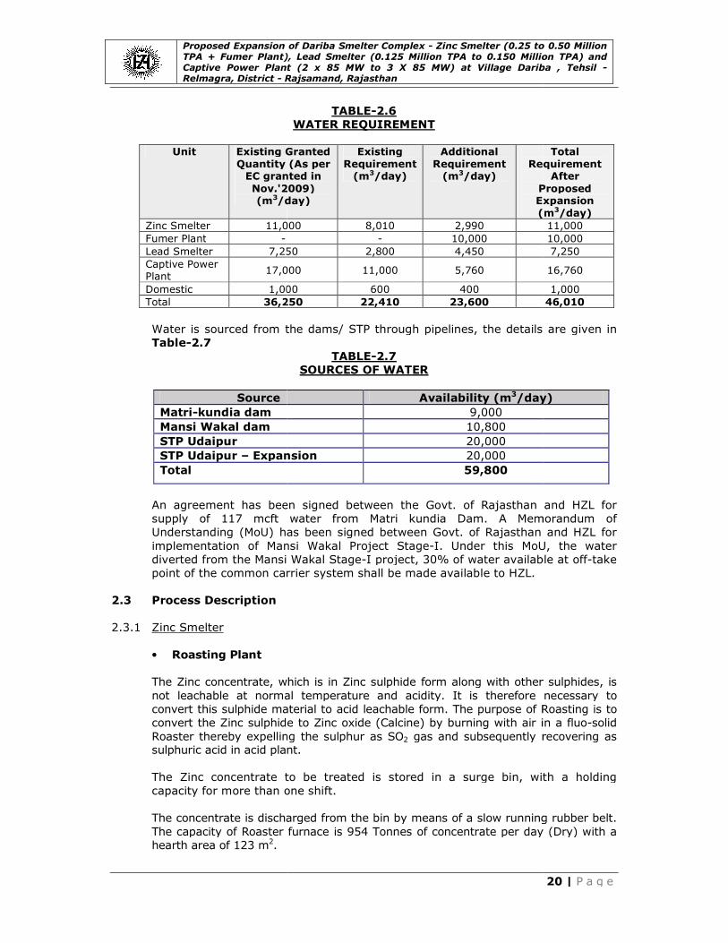
TABLE-2.6
WATER REQUIREMENT
Existing Granted
Quantity (As per EC granted in
Nov.'2009) /day)
Existing
Requirement (m3/day)
Additional
Requirement (m3/day)
Requirement
Proposed Expansion
(m
000 8,010 2,990
- 10,000
250 2,800 4,450
000 11,000 5,760
000 600 400
250 22,410 23,600
Water is sourced from the dams/ STP through pipelines, the details are given in
TABLE-2.7
SOURCES OF WATER
Availability (m3/day)
9,000
10,800
20,000
Expansion 20,000
59,800
An agreement has been signed between the Govt. of Rajasthan and HZL for
supply of 117 mcft water from Matri kundia Dam. A Memorandum of
Understanding (MoU) has been signed between Govt. of Rajasthan and HZL for
implementation of Mansi Wakal Project Stage-I. Under this MoU, the water
Wakal Stage-I project, 30% of water available at off
point of the common carrier system shall be made available to HZL.
concentrate, which is in Zinc sulphide form along with other sulphides, is
not leachable at normal temperature and acidity. It is therefore necessary to
convert this sulphide material to acid leachable form. The purpose of Roasting is to
sulphide to Zinc oxide (Calcine) by burning with air in a fluo
Roaster thereby expelling the sulphur as SO2 gas and subsequently recovering as sulphuric acid in acid plant.
concentrate to be treated is stored in a surge bin, with a holding
acity for more than one shift.
The concentrate is discharged from the bin by means of a slow running rubber belt.
The capacity of Roaster furnace is 954 Tonnes of concentrate per day (Dry) with a
Zinc Smelter (0.25 to 0.50 Million TPA + Fumer Plant), Lead Smelter (0.125 Million TPA to 0.150 Million TPA) and Captive Power Plant (2 x 85 MW to 3 X 85 MW) at Village Dariba , Tehsil -
20 | P a g e
Total
Requirement After
Proposed Expansion
(m3/day)
11,000
10,000
7,250
16,760
1,000
46,010
through pipelines, the details are given in
/day)
An agreement has been signed between the Govt. of Rajasthan and HZL for
kundia Dam. A Memorandum of
Understanding (MoU) has been signed between Govt. of Rajasthan and HZL for
I. Under this MoU, the water
I project, 30% of water available at off-take
sulphide form along with other sulphides, is
not leachable at normal temperature and acidity. It is therefore necessary to
convert this sulphide material to acid leachable form. The purpose of Roasting is to
) by burning with air in a fluo-solid
gas and subsequently recovering as
concentrate to be treated is stored in a surge bin, with a holding
The concentrate is discharged from the bin by means of a slow running rubber belt.
The capacity of Roaster furnace is 954 Tonnes of concentrate per day (Dry) with a

Proposed Expansion of Dariba Smelter Complex TPA + Fumer Plant), Lead Smelter (0.125 Million TPA to 0.150 Million TPA) and Captive Power Plant (2 x 85 MW to 3 X 85 MW) at Village Dariba , Relmagra, District - R
The principal roasting reactions
2ZnS + 3O2 = => 2 ZnO + 2SO
4FeS + 7O2 = => 2Fe2O
ZnO + Fe2O3 = => ZnOFe
In order to avoid any gas leakage, in particular through the charge openings, the
furnace is maintained under a slight
by the SO2 gas blower and controlled by a louver type damper. The roasting gas
at the furnace exit has a temperature of about 950 to 1000of approximately 9% (Vol.). In a waste heat boiler, t
3500C.
The waste heat boiler is of the forced circulation type. It is designed to produce
superheated steam at ~40 bar / 400
walls and the use of evaporator bundles. All the bundles ar
boiler roof. To avoid any air ingress, the roof is tight welded. A part of the flue
dust may adhere on the tube surface; all the bundles are equipped with an
effective rapping device, controlled by a timer to make this adhering calcine
fall. The rapping periods may be set as required to optimize operation.
Only de-aerated and treated feed water will be used for the boiler. This water is
prepared in the de-mineralized water treatment plant. It is fed into the boiler
drum by means of a boiler feed pump. From the drum, the circulating pump
delivers the water into the evaporator bundles and wall tubes and the cooling
coils of the roaster.
The calcine, collected in the waste heat boiler, drops into a longitudinal hopper
arranged underneath the boiler and is discharged by a conti
chain conveyor and water
roaster and waste heat boiler, passes through a rotating drum cooler, to be
cooled to a temperature below 150
The cooler discharge then passes through a ball mill. The mill discharge and the
fine dust coming from the cyclone and hot gas precipitator are combined and
transported to an intermediate bin. From the intermediate bin the calcine
pneumatically transported to the leaching plant. A bag filter is provided to ensure
de-dusting of the calcine handling system.
Before the first start-up, as well as for start
bed furnace and the waste heat boiler h
roaster is equipped with a preheating unit for starting
consists of an oil tank with a pump, oil burners and oil lances. The necessary
combustion air is taken from an air blower. Start
start-up fan and vented via a start
cleaning section.
• Gas Cleaning
The purpose of gas cleaning is to clean the gases of dust particles, saturated with
water vapour, cooling and making it optically clear by removing the mist
particles, thereby making it suitable for feed to the acid plant.
Proposed Expansion of Dariba Smelter Complex - Zinc Smelter (0.25 to 0.50 Million TPA + Fumer Plant), Lead Smelter (0.125 Million TPA to 0.150 Million TPA) and Captive Power Plant (2 x 85 MW to 3 X 85 MW) at Village Dariba ,
Rajsamand, Rajasthan
The principal roasting reactions are as follows;
= => 2 ZnO + 2SO2 + 223.6 Kcal
O3 + 4SO2+ Heat
= => ZnOFe2O3 (Zinc ferrite)
In order to avoid any gas leakage, in particular through the charge openings, the
furnace is maintained under a slight negative pressure. This draught is provided
gas blower and controlled by a louver type damper. The roasting gas
at the furnace exit has a temperature of about 950 to 10000C and a SOof approximately 9% (Vol.). In a waste heat boiler, the gas is cooled to about
The waste heat boiler is of the forced circulation type. It is designed to produce
superheated steam at ~40 bar / 4000C. The boiler design provides for tube lined
walls and the use of evaporator bundles. All the bundles are suspended at the
boiler roof. To avoid any air ingress, the roof is tight welded. A part of the flue
dust may adhere on the tube surface; all the bundles are equipped with an
effective rapping device, controlled by a timer to make this adhering calcine
fall. The rapping periods may be set as required to optimize operation.
aerated and treated feed water will be used for the boiler. This water is
mineralized water treatment plant. It is fed into the boiler
boiler feed pump. From the drum, the circulating pump
delivers the water into the evaporator bundles and wall tubes and the cooling
The calcine, collected in the waste heat boiler, drops into a longitudinal hopper
arranged underneath the boiler and is discharged by a continuous air
chain conveyor and water-cooled rotary valve. The calcine, collected from the
roaster and waste heat boiler, passes through a rotating drum cooler, to be
temperature below 1500C.
The cooler discharge then passes through a ball mill. The mill discharge and the
fine dust coming from the cyclone and hot gas precipitator are combined and
transported to an intermediate bin. From the intermediate bin the calcine
pneumatically transported to the leaching plant. A bag filter is provided to ensure
dusting of the calcine handling system.
up, as well as for start-ups after long shutdowns, the fluid
bed furnace and the waste heat boiler have to be preheated. For this purpose the
roaster is equipped with a preheating unit for starting-up purposes, which
consists of an oil tank with a pump, oil burners and oil lances. The necessary
combustion air is taken from an air blower. Start-up gases are withdrawn by a
up fan and vented via a start-up stack to the atmosphere provided after gas
The purpose of gas cleaning is to clean the gases of dust particles, saturated with
water vapour, cooling and making it optically clear by removing the mist
particles, thereby making it suitable for feed to the acid plant.
Zinc Smelter (0.25 to 0.50 Million TPA + Fumer Plant), Lead Smelter (0.125 Million TPA to 0.150 Million TPA) and Captive Power Plant (2 x 85 MW to 3 X 85 MW) at Village Dariba , Tehsil -
21 | P a g e
In order to avoid any gas leakage, in particular through the charge openings, the
negative pressure. This draught is provided
gas blower and controlled by a louver type damper. The roasting gas
C and a SO2 content he gas is cooled to about
The waste heat boiler is of the forced circulation type. It is designed to produce
C. The boiler design provides for tube lined
e suspended at the
boiler roof. To avoid any air ingress, the roof is tight welded. A part of the flue
dust may adhere on the tube surface; all the bundles are equipped with an
effective rapping device, controlled by a timer to make this adhering calcine to
fall. The rapping periods may be set as required to optimize operation.
aerated and treated feed water will be used for the boiler. This water is
mineralized water treatment plant. It is fed into the boiler
boiler feed pump. From the drum, the circulating pump
delivers the water into the evaporator bundles and wall tubes and the cooling
The calcine, collected in the waste heat boiler, drops into a longitudinal hopper
nuous air-cooled
The calcine, collected from the
roaster and waste heat boiler, passes through a rotating drum cooler, to be
The cooler discharge then passes through a ball mill. The mill discharge and the
fine dust coming from the cyclone and hot gas precipitator are combined and
transported to an intermediate bin. From the intermediate bin the calcine is
pneumatically transported to the leaching plant. A bag filter is provided to ensure
ups after long shutdowns, the fluid
ave to be preheated. For this purpose the
up purposes, which
consists of an oil tank with a pump, oil burners and oil lances. The necessary
re withdrawn by a
up stack to the atmosphere provided after gas
The purpose of gas cleaning is to clean the gases of dust particles, saturated with
water vapour, cooling and making it optically clear by removing the mist

Proposed Expansion of Dariba Smelter Complex TPA + Fumer Plant), Lead Smelter (0.125 Million TPA to 0.150 Million TPA) and Captive Power Plant (2 x 85 MW to 3 X 85 MW) at Village Dariba , Relmagra, District - R
The gas cleaning section
1. Hot gas cleaning
2. Wet gas cooling/condensing
3. Acid mist precipitator
4. Mercury removal system
1. Hot Gas Cleaning
The dust loaded SO2 gases from the waste heat boiler are deline three field hot ESP.
The hot gas electrostatic precipitator comprises of three separate electrostatic
fields arranged in series. The dust particles are charged and separated on the
collecting electrodes by the influence of the electrostatic fields. A gas distribution
plate located at the electrostatic precipitator inlet ensures the even gas
distribution over the sectional area of the electrostatic precipitator. The dust
adhering to the collecting electrodes, discharge electrodes and gas distribution
plate is removed at certain intervals by motorized rappers.
The removed dust drops into a longitudinal hopper arranged below the electrostatic precipitator casing and is discharged by a continuously operating
dust conveyor and two rotary valves arranged in series. The col
consist of cold-rolled strips of steel plate. They are arranged in passages. The
discharge electrodes of large cross section are rigidly fixed into pipe frames,
which are vertically suspended between the collecting electrodes. This rigid
design is highly efficient.
Both electrode system
equipped with highly efficient motorized rapping systems. Hot purge air will be
injected to prevent any condensation of Sulphuric acid mists o
supporting insulators of the discharge electrode systems.
The casing of the electrostatic precipitator will be fabricated from steel sheet and
welded gas tight. It has to be fitted with particularly carefully designed heat
insulation to avoid condensation of Sulphuric acid and corrosion. Each
transformer rectifier is controlled by an automatic high voltage control system.
2. Wet Gas Cleaning
Washing Tower
After pre-cleaning in the hot
gas section equipped with a washing tower, which cools the gas adiabatically to a
temperature of about 60
serves to wash out the bulk of the solids entering from the hot gas ESP’s, as well
as condensed volatile impurities. Excess liquid will be discharged to a stripper for
SO2 removal.
Cooling Tower
The cooling of the SO2
current flow, cooling liquid (weak acid) is sprayed into the tower and
downward through packing. By direct contact between the warm gases and the
cooling liquid, heat is transferred. Flue gas cools down, gaseous water condenses
Proposed Expansion of Dariba Smelter Complex - Zinc Smelter (0.25 to 0.50 Million TPA + Fumer Plant), Lead Smelter (0.125 Million TPA to 0.150 Million TPA) and Captive Power Plant (2 x 85 MW to 3 X 85 MW) at Village Dariba ,
Rajsamand, Rajasthan
The gas cleaning section consists of the following units:
Wet gas cooling/condensing
Acid mist precipitator
Mercury removal system
gases from the waste heat boiler are de-dusted in one single
The hot gas electrostatic precipitator comprises of three separate electrostatic
fields arranged in series. The dust particles are charged and separated on the
collecting electrodes by the influence of the electrostatic fields. A gas distribution
plate located at the electrostatic precipitator inlet ensures the even gas
distribution over the sectional area of the electrostatic precipitator. The dust
adhering to the collecting electrodes, discharge electrodes and gas distribution
t certain intervals by motorized rappers.
The removed dust drops into a longitudinal hopper arranged below the electrostatic precipitator casing and is discharged by a continuously operating
dust conveyor and two rotary valves arranged in series. The collecting electrodes
rolled strips of steel plate. They are arranged in passages. The
discharge electrodes of large cross section are rigidly fixed into pipe frames,
which are vertically suspended between the collecting electrodes. This rigid
design is highly efficient.
Both electrode system – collecting electrodes and discharge electrodes
equipped with highly efficient motorized rapping systems. Hot purge air will be
injected to prevent any condensation of Sulphuric acid mists on the surface of the
supporting insulators of the discharge electrode systems.
The casing of the electrostatic precipitator will be fabricated from steel sheet and
welded gas tight. It has to be fitted with particularly carefully designed heat
to avoid condensation of Sulphuric acid and corrosion. Each
transformer rectifier is controlled by an automatic high voltage control system.
cleaning in the hot-gas cleaning system, the gas is routed to the
gas section equipped with a washing tower, which cools the gas adiabatically to a
temperature of about 600C by means of circulating liquid. The washing tower also
serves to wash out the bulk of the solids entering from the hot gas ESP’s, as well
densed volatile impurities. Excess liquid will be discharged to a stripper for
2 gas is done in a packed gas-cooling tower. In counter
current flow, cooling liquid (weak acid) is sprayed into the tower and
downward through packing. By direct contact between the warm gases and the
cooling liquid, heat is transferred. Flue gas cools down, gaseous water condenses
Zinc Smelter (0.25 to 0.50 Million TPA + Fumer Plant), Lead Smelter (0.125 Million TPA to 0.150 Million TPA) and Captive Power Plant (2 x 85 MW to 3 X 85 MW) at Village Dariba , Tehsil -
22 | P a g e
dusted in one single
The hot gas electrostatic precipitator comprises of three separate electrostatic
fields arranged in series. The dust particles are charged and separated on the
collecting electrodes by the influence of the electrostatic fields. A gas distribution
plate located at the electrostatic precipitator inlet ensures the even gas
distribution over the sectional area of the electrostatic precipitator. The dust
adhering to the collecting electrodes, discharge electrodes and gas distribution
The removed dust drops into a longitudinal hopper arranged below the electrostatic precipitator casing and is discharged by a continuously operating
lecting electrodes
rolled strips of steel plate. They are arranged in passages. The
discharge electrodes of large cross section are rigidly fixed into pipe frames,
which are vertically suspended between the collecting electrodes. This rigid frame
collecting electrodes and discharge electrodes – are
equipped with highly efficient motorized rapping systems. Hot purge air will be
n the surface of the
The casing of the electrostatic precipitator will be fabricated from steel sheet and
welded gas tight. It has to be fitted with particularly carefully designed heat
to avoid condensation of Sulphuric acid and corrosion. Each
transformer rectifier is controlled by an automatic high voltage control system.
gas cleaning system, the gas is routed to the wet
gas section equipped with a washing tower, which cools the gas adiabatically to a
C by means of circulating liquid. The washing tower also
serves to wash out the bulk of the solids entering from the hot gas ESP’s, as well
densed volatile impurities. Excess liquid will be discharged to a stripper for
cooling tower. In counter
current flow, cooling liquid (weak acid) is sprayed into the tower and flows
downward through packing. By direct contact between the warm gases and the
cooling liquid, heat is transferred. Flue gas cools down, gaseous water condenses
Proposed Expansion of Dariba Smelter Complex TPA + Fumer Plant), Lead Smelter (0.125 Million TPA to 0.150 Million TPA) and Captive Power Plant (2 x 85 MW to 3 X 85 MW) at Village Dariba , Relmagra, District - R
and the cooling liquid is heated. The condensate leaving the cooling tower is
collected in its sump from where it is delivered to the nozzles by means
cooler flushing pump. The surplus of condensate is withdrawn by gravity from the
sump to the washing tower weak acid circuit.
3. Acid Mist Precipitator
From the washing and cooling sect
ESP’s for mist elimination arranged in two stages. These ESP’s are of the proven
tubular type and are constructed mainly of plastic with high mechanical strength and a high chemical resistance. All parts in co
homogeneously Lead-lined steel. The materials are selected according to the
operating environment and stresses acting on the various components. The
gases pass through the ESP tubes in a vertical direction, in the firs
upwards and in the second stage flowing downwards. Spike design of discharge
electrodes ensure that the mist particles are charged and separated on the tubes.
The discharged condensate flows as a film along the tube surface to be collected
in the bottom section of the ESP from where it is drained. The condensate stream
is combined with the wash acid in the washing tower.
4. Mercury Removal System (Calomel Process)
The mercury contained in
mercury vapour during roasting. Some of the mercury may condense or re
combine with other components in the gas to form insoluble compounds. These
particles or compounds may be separated in the conventional
cleaning and cooling before the gases enter the Sulphuric acid plant. But some
amount of mercury vapour passes the conventional gas cooling and cleaning
system as metallic vapour that must be removed from the gas before feeding to
sulphuric acid plant.
Description of Mercury Removal System
The calomel process was originally developed for the purpose of removing
mercury vapour from Zinc
been treated in the conventional cleaning, washing and c
The reactor for removal of mercury treats gases at a temperature of 38
reactor is a counter current absorption tower made of glass fiber reinforced
plastic. The tower is packed with plastic rings made of polypropylene. The HgCl
solution is sprayed over the packing by nozzles. The mercury vapour comes in
contact with mercuric chloride solution and transforms to mercurous chloride.
When mercury content in circulating water increases, some of the mercurous
chloride is taken to a ch
chloride, which is used as make
(calomel) is withdrawn periodically and stored for sale to interested buyers. The
main reactions are as follows:
HgCl2 (l) + Hg0 (gas) ==> Hg
Hg2Cl2 (s) + Cl2 (gas) ==> 2 HgCl
The towers are furnished with demisters in order to prevent drops leaving the
tower with the purified gases. The clean gas then goes to sulphuric acid plant for
production of H2SO4.
Proposed Expansion of Dariba Smelter Complex - Zinc Smelter (0.25 to 0.50 Million TPA + Fumer Plant), Lead Smelter (0.125 Million TPA to 0.150 Million TPA) and Captive Power Plant (2 x 85 MW to 3 X 85 MW) at Village Dariba ,
Rajsamand, Rajasthan
and the cooling liquid is heated. The condensate leaving the cooling tower is
its sump from where it is delivered to the nozzles by means
The surplus of condensate is withdrawn by gravity from the
sump to the washing tower weak acid circuit.
3. Acid Mist Precipitator
From the washing and cooling section, the gases are forwarded into two wet gas
ESP’s for mist elimination arranged in two stages. These ESP’s are of the proven
tubular type and are constructed mainly of plastic with high mechanical strength and a high chemical resistance. All parts in contact with the gas are of plastic or
lined steel. The materials are selected according to the
operating environment and stresses acting on the various components. The
gases pass through the ESP tubes in a vertical direction, in the first stage flowing
upwards and in the second stage flowing downwards. Spike design of discharge
electrodes ensure that the mist particles are charged and separated on the tubes.
The discharged condensate flows as a film along the tube surface to be collected
in the bottom section of the ESP from where it is drained. The condensate stream
is combined with the wash acid in the washing tower.
4. Mercury Removal System (Calomel Process)
The mercury contained in Zinc concentrate is transferred mainly into metallic
mercury vapour during roasting. Some of the mercury may condense or re
combine with other components in the gas to form insoluble compounds. These
particles or compounds may be separated in the conventional
cleaning and cooling before the gases enter the Sulphuric acid plant. But some
amount of mercury vapour passes the conventional gas cooling and cleaning
system as metallic vapour that must be removed from the gas before feeding to
Description of Mercury Removal System
The calomel process was originally developed for the purpose of removing
Zinc concentrates roaster gases, after these gases have
been treated in the conventional cleaning, washing and cooling plant.
The reactor for removal of mercury treats gases at a temperature of 38
reactor is a counter current absorption tower made of glass fiber reinforced
plastic. The tower is packed with plastic rings made of polypropylene. The HgCl
solution is sprayed over the packing by nozzles. The mercury vapour comes in
contact with mercuric chloride solution and transforms to mercurous chloride.
When mercury content in circulating water increases, some of the mercurous
chloride is taken to a chlorination tank to convert mercurous chloride to mercuric
chloride, which is used as make-up in circulating water. The mercurous chloride
(calomel) is withdrawn periodically and stored for sale to interested buyers. The
main reactions are as follows:
(l) + Hg0 (gas) ==> Hg2Cl2 (s)
(gas) ==> 2 HgCl2 (l)
The towers are furnished with demisters in order to prevent drops leaving the
tower with the purified gases. The clean gas then goes to sulphuric acid plant for
Zinc Smelter (0.25 to 0.50 Million TPA + Fumer Plant), Lead Smelter (0.125 Million TPA to 0.150 Million TPA) and Captive Power Plant (2 x 85 MW to 3 X 85 MW) at Village Dariba , Tehsil -
23 | P a g e
and the cooling liquid is heated. The condensate leaving the cooling tower is
its sump from where it is delivered to the nozzles by means of a gas
The surplus of condensate is withdrawn by gravity from the
ion, the gases are forwarded into two wet gas
ESP’s for mist elimination arranged in two stages. These ESP’s are of the proven
tubular type and are constructed mainly of plastic with high mechanical strength ntact with the gas are of plastic or
lined steel. The materials are selected according to the
operating environment and stresses acting on the various components. The
t stage flowing
upwards and in the second stage flowing downwards. Spike design of discharge
electrodes ensure that the mist particles are charged and separated on the tubes.
The discharged condensate flows as a film along the tube surface to be collected
in the bottom section of the ESP from where it is drained. The condensate stream
concentrate is transferred mainly into metallic
mercury vapour during roasting. Some of the mercury may condense or re-
combine with other components in the gas to form insoluble compounds. These
particles or compounds may be separated in the conventional unit for gas
cleaning and cooling before the gases enter the Sulphuric acid plant. But some
amount of mercury vapour passes the conventional gas cooling and cleaning
system as metallic vapour that must be removed from the gas before feeding to
The calomel process was originally developed for the purpose of removing
concentrates roaster gases, after these gases have
ooling plant.
The reactor for removal of mercury treats gases at a temperature of 380C. The
reactor is a counter current absorption tower made of glass fiber reinforced
plastic. The tower is packed with plastic rings made of polypropylene. The HgCl2
solution is sprayed over the packing by nozzles. The mercury vapour comes in
contact with mercuric chloride solution and transforms to mercurous chloride.
When mercury content in circulating water increases, some of the mercurous
lorination tank to convert mercurous chloride to mercuric
up in circulating water. The mercurous chloride
(calomel) is withdrawn periodically and stored for sale to interested buyers. The
The towers are furnished with demisters in order to prevent drops leaving the
tower with the purified gases. The clean gas then goes to sulphuric acid plant for
Proposed Expansion of Dariba Smelter Complex TPA + Fumer Plant), Lead Smelter (0.125 Million TPA to 0.150 Million TPA) and Captive Power Plant (2 x 85 MW to 3 X 85 MW) at Village Dariba , Relmagra, District - R
• Sulphuric Acid Plant
The SO2 gas from the gas cleaning section is converted to sulphuric acid by first
converting the SO2 to SO
converter has four layers of V
and passed on to intermediate absorption tower where the SO
produce sulphuric acid. The residual SO
4thmass in order to achieve maximum conversion effic
SO3 gas after 3rd mass and converting it to Hto SO3 in fourth mass. Conversion of SO
in two stages is known as double conversion and double absorption (DCDA
this process, the conversion of SO
thus allowing very low SO
The Sulphuric acid plant mainly consists of 3 plant sections:
• The drying and absorption section
• The converter section with the gas
• The product acid tank farm
1. Drying and Absorption Section
The drying and absorption section mainly consists of the drying tower, the
intermediate absorber, the final absorber, the acid pumps, the acid pump
the acid coolers and the acid piping.
The gas flow through the towers is counter
flows from the bottom to the top of the tower. From the bottom of the tower(s)
the acid flows to the pump tank and is pumped fro
the acid coolers) back to the spray system.
Acid transfer lines between the drying tower, the intermediate absorber and the final absorber and injection lines for dilution water at the intermediate absorber
and final absorber allow control of the necessary acid concentration for each of
the towers.
The Sulphuric acid is produced as +98% H
from the final absorber pump tank. The acid is then cooled in the product acid
cooler and pumped to the
a. Converter System
In the converter, the SO
presence of Vanadium Pentoxide as catalyst, which is subsequently absorbed in
acid towers to convert into sulphuric acid.
The converter system consists of a four
intermediate absorption is follo
an insulated, vertical and cylindrical vessel divided in four sections called layers
or trays with a central tube. The catalyst required for the conversion of SO
SO3 is arranged on these layers. The
and down stream through layer 2, 3, 4.
Proposed Expansion of Dariba Smelter Complex - Zinc Smelter (0.25 to 0.50 Million TPA + Fumer Plant), Lead Smelter (0.125 Million TPA to 0.150 Million TPA) and Captive Power Plant (2 x 85 MW to 3 X 85 MW) at Village Dariba ,
Rajsamand, Rajasthan
Sulphuric Acid Plant
gas from the gas cleaning section is converted to sulphuric acid by first
to SO3 in converter in presence of V2O5 as catalyst. The
converter has four layers of V2O5 catalyst. After 3rd mass, the gas is withdrawn
and passed on to intermediate absorption tower where the SO3 gas is absorbed to
produce sulphuric acid. The residual SO2 is further converted to SO
mass in order to achieve maximum conversion efficiency. The withdrawal of
gas after 3rd mass and converting it to H2SO4 accelerates conversion of SOin fourth mass. Conversion of SO2 to SO3 in two stages and absorbing SO
in two stages is known as double conversion and double absorption (DCDA
this process, the conversion of SO2 to SO3 gas is very high (more than 99.7%)
thus allowing very low SO2 emission (less than 650 mg/Nm3).
plant mainly consists of 3 plant sections:
The drying and absorption section
section with the gas-to-gas heat exchangers
The product acid tank farm
1. Drying and Absorption Section
The drying and absorption section mainly consists of the drying tower, the
intermediate absorber, the final absorber, the acid pumps, the acid pump
the acid coolers and the acid piping.
The gas flow through the towers is counter-current to the acid flow, i.e. the gas
flows from the bottom to the top of the tower. From the bottom of the tower(s)
the acid flows to the pump tank and is pumped from there by the acid pumps (via
the acid coolers) back to the spray system.
Acid transfer lines between the drying tower, the intermediate absorber and the final absorber and injection lines for dilution water at the intermediate absorber
r allow control of the necessary acid concentration for each of
The Sulphuric acid is produced as +98% H2SO4 and the product acid is taken
from the final absorber pump tank. The acid is then cooled in the product acid
cooler and pumped to the existing acid storage tanks.
In the converter, the SO2 bearing gas is converted to SO3 (sulphur trioxide) in the
presence of Vanadium Pentoxide as catalyst, which is subsequently absorbed in
acid towers to convert into sulphuric acid.
The converter system consists of a four-layer central tube converter. The
intermediate absorption is following outlet of the 3rd layer. The converter itself is
an insulated, vertical and cylindrical vessel divided in four sections called layers
or trays with a central tube. The catalyst required for the conversion of SO
is arranged on these layers. The SO2 gas flows up stream through layer 1
and down stream through layer 2, 3, 4.
Zinc Smelter (0.25 to 0.50 Million TPA + Fumer Plant), Lead Smelter (0.125 Million TPA to 0.150 Million TPA) and Captive Power Plant (2 x 85 MW to 3 X 85 MW) at Village Dariba , Tehsil -
24 | P a g e
gas from the gas cleaning section is converted to sulphuric acid by first
as catalyst. The
catalyst. After 3rd mass, the gas is withdrawn
gas is absorbed to
is further converted to SO3 gas in
iency. The withdrawal of
accelerates conversion of SO2 in two stages and absorbing SO3
in two stages is known as double conversion and double absorption (DCDA). In
gas is very high (more than 99.7%)
The drying and absorption section mainly consists of the drying tower, the
intermediate absorber, the final absorber, the acid pumps, the acid pump tanks,
current to the acid flow, i.e. the gas
flows from the bottom to the top of the tower. From the bottom of the tower(s)
m there by the acid pumps (via
Acid transfer lines between the drying tower, the intermediate absorber and the final absorber and injection lines for dilution water at the intermediate absorber
r allow control of the necessary acid concentration for each of
and the product acid is taken
from the final absorber pump tank. The acid is then cooled in the product acid
(sulphur trioxide) in the
presence of Vanadium Pentoxide as catalyst, which is subsequently absorbed in
layer central tube converter. The
wing outlet of the 3rd layer. The converter itself is
an insulated, vertical and cylindrical vessel divided in four sections called layers
or trays with a central tube. The catalyst required for the conversion of SO2 to
gas flows up stream through layer 1

Proposed Expansion of Dariba Smelter Complex TPA + Fumer Plant), Lead Smelter (0.125 Million TPA to 0.150 Million TPA) and Captive Power Plant (2 x 85 MW to 3 X 85 MW) at Village Dariba , Relmagra, District - R
Three gas-to-gas heat exchangers II, III and IV are designed as mixed cross
flow/counter flow shell and tube heat exchangers. These heat exchangers mainly
consist of inlet and out let chambers, the tube sheets, the tubes and baffles. Heat
exchanger III ensures the optimum gas temperature for the intermediate
absorber as well as for the inlet of layer 4.
Another heat exchanger I, inside the converter, arranged in the bottom of
central tube between layer 1 and 2, is designed as counter flow for pre heating
SO2 gas to the inlet temperature of layer 1.
b. SO2 Gas Blower
The SO2 gas blower is arranged downstream of the drying tower and routes the
gas from the Zinc roaster sec
acid plant. The blower will be provided with an electric motor.
c. Pre-heater
A pre-heater is needed to preheat the converter system from cold condition to
operating temperature, whereas during normal
released within the process allows autoaddition, lower or varying SO
pre-heater preheats air or, in the start phases, SO
temperature.
d. Process Criteria for the Acid Plant
For the production of the sulphuric acid, SO
concentrate roasting are used. There are four main process criteria in the
production of these kinds of gases by the contact/converter process. They are
o Gas drying;
o Water balance; o Heat balance;
o Conversion of SO2 to SO
Gas Drying
Gas drying is an important process in this type of contact plant. Gas drying
protects cooler parts of the plant, such as heat exchangers, against corrosion by
acid condensation. It safeguards against the formation of acid mist, which can be
very difficult to absorb at a latter stage of the process. It also protects the
catalyst from acid condensation during plant shutdowns. Therefore, the life of the
plant and also the tail gas purity largely depend on appropriate gas drying.
The substantial amount of heat, not just the heat of dilution of the sulphuric acid
but also the heat of condensation of the water, is liberated in the gas drying
stage. For that reason the circulated acid is generally cooled by indirect heat
exchanger before being recycled t
Water Balance
The water balance of contact sulphuric acid plants in general may simply be
defined by the specific amount of process water required for achieving the desired
product acid strength from the amount of SO
Proposed Expansion of Dariba Smelter Complex - Zinc Smelter (0.25 to 0.50 Million TPA + Fumer Plant), Lead Smelter (0.125 Million TPA to 0.150 Million TPA) and Captive Power Plant (2 x 85 MW to 3 X 85 MW) at Village Dariba ,
Rajsamand, Rajasthan
gas heat exchangers II, III and IV are designed as mixed cross
flow/counter flow shell and tube heat exchangers. These heat exchangers mainly
d out let chambers, the tube sheets, the tubes and baffles. Heat
exchanger III ensures the optimum gas temperature for the intermediate
absorber as well as for the inlet of layer 4.
Another heat exchanger I, inside the converter, arranged in the bottom of
central tube between layer 1 and 2, is designed as counter flow for pre heating
gas to the inlet temperature of layer 1.
gas blower is arranged downstream of the drying tower and routes the
roaster section via the gas cleaning plant through the Sulphuric
acid plant. The blower will be provided with an electric motor.
heater is needed to preheat the converter system from cold condition to
operating temperature, whereas during normal operation of the plant the heat
released within the process allows auto-thermal operation of the plant. In addition, lower or varying SO2-concentrations can be compensated. The separate
heater preheats air or, in the start phases, SO2-gas to the requi
d. Process Criteria for the Acid Plant
For the production of the sulphuric acid, SO2 containing gases from the
concentrate roasting are used. There are four main process criteria in the
production of these kinds of gases by the contact/converter process. They are
to SO3 at the required O2/SO2 ratio.
Gas drying is an important process in this type of contact plant. Gas drying
protects cooler parts of the plant, such as heat exchangers, against corrosion by
acid condensation. It safeguards against the formation of acid mist, which can be
difficult to absorb at a latter stage of the process. It also protects the
catalyst from acid condensation during plant shutdowns. Therefore, the life of the
plant and also the tail gas purity largely depend on appropriate gas drying.
nt of heat, not just the heat of dilution of the sulphuric acid
but also the heat of condensation of the water, is liberated in the gas drying
stage. For that reason the circulated acid is generally cooled by indirect heat
exchanger before being recycled to the dryer.
The water balance of contact sulphuric acid plants in general may simply be
defined by the specific amount of process water required for achieving the desired
product acid strength from the amount of SO2 converted to SO3.
Zinc Smelter (0.25 to 0.50 Million TPA + Fumer Plant), Lead Smelter (0.125 Million TPA to 0.150 Million TPA) and Captive Power Plant (2 x 85 MW to 3 X 85 MW) at Village Dariba , Tehsil -
25 | P a g e
gas heat exchangers II, III and IV are designed as mixed cross
flow/counter flow shell and tube heat exchangers. These heat exchangers mainly
d out let chambers, the tube sheets, the tubes and baffles. Heat
exchanger III ensures the optimum gas temperature for the intermediate
Another heat exchanger I, inside the converter, arranged in the bottom of the
central tube between layer 1 and 2, is designed as counter flow for pre heating
gas blower is arranged downstream of the drying tower and routes the
tion via the gas cleaning plant through the Sulphuric
heater is needed to preheat the converter system from cold condition to
operation of the plant the heat
thermal operation of the plant. In concentrations can be compensated. The separate
gas to the required
containing gases from the Zinc
concentrate roasting are used. There are four main process criteria in the
production of these kinds of gases by the contact/converter process. They are
Gas drying is an important process in this type of contact plant. Gas drying
protects cooler parts of the plant, such as heat exchangers, against corrosion by
acid condensation. It safeguards against the formation of acid mist, which can be
difficult to absorb at a latter stage of the process. It also protects the
catalyst from acid condensation during plant shutdowns. Therefore, the life of the
plant and also the tail gas purity largely depend on appropriate gas drying.
nt of heat, not just the heat of dilution of the sulphuric acid
but also the heat of condensation of the water, is liberated in the gas drying
stage. For that reason the circulated acid is generally cooled by indirect heat
The water balance of contact sulphuric acid plants in general may simply be
defined by the specific amount of process water required for achieving the desired
Proposed Expansion of Dariba Smelter Complex TPA + Fumer Plant), Lead Smelter (0.125 Million TPA to 0.150 Million TPA) and Captive Power Plant (2 x 85 MW to 3 X 85 MW) at Village Dariba , Relmagra, District - R
In the case of acid gas plants (like roaster plants) the process water requirements
are usually balanced nearly completely by the water vapour content of the SO
feed gases entering in the drying tower except for a small margin necessary for
the automatic acid strength control.
Thus at a given SO2 gas concentration and SO
product acid strength, the only variable that can and has to be controlled or
limited is water vapour content of the feed gasses entering the drying tower in
order not to exceed the water balance of the whole system. This is done in the wet gas purification system by cooling the SO
temperature corresponding to the maximum allowable water vapour content. For
determination of the req
consider the negative pressure, for which the gas purification system is designed,
but also the external barometric pressure, which depends largely on the elevation
of the plant above sea level.
Absorption of SO3
Sulphur trioxide formed by catalytic oxidation of sulphur dioxide is absorbed in
sulphuric acid of at least 98% concentration, in which it reacts with existing or added water to form more sulphuric acid. The process gas leaving the conve
system is cooled, first in a gas
1600 C before entering the absorber. The gas entering the absorber is therefore
not completely cold and it transfers heat to absorber acid as it passes through
absorber, by the time it reach
as the incoming absorber acid.
A substantial amount of heat is also generated in the absorber acid from the
absorption of sulphur trioxide and the formation of sulphuric acid, and t
temperature rises as a result by a margin, which depends on the acid circulation
rate. The acid concentration is maintained constant by adding process water to
the acid leaving the absorber and the acid cross flow from the dryer (to the intermediate absorber only) at a rate controlled by a concentration measuring
device. The circulated acid is cooled by indirect cooling.
Heat Balance
The SO2 gases leaving the wet gas cleaning system enter the acid plant at a
temperature of 350-400C (depending on
the residual water content in the dryer, the process gases must be heated up to
the required converter inlet temperature of 440
heat exchange with the available sensible gas heat relea
the converter. The main objective of designing such a cold gas plant is to attain
auto thermal operating conditions, which becomes primarily a question of the
required gas heat exchanger surface, depending on the feed gas SO
concentration.
The reaction heat in a double catalysis plant based on roaster gases is released
from;
- Catalytic oxidation
SO2 + ½O2 ==> SO3 + 23.45 Kcal
- Sulphur trioxide absorption and sulphuric acid formation
Proposed Expansion of Dariba Smelter Complex - Zinc Smelter (0.25 to 0.50 Million TPA + Fumer Plant), Lead Smelter (0.125 Million TPA to 0.150 Million TPA) and Captive Power Plant (2 x 85 MW to 3 X 85 MW) at Village Dariba ,
Rajsamand, Rajasthan
the case of acid gas plants (like roaster plants) the process water requirements
are usually balanced nearly completely by the water vapour content of the SO
feed gases entering in the drying tower except for a small margin necessary for
d strength control.
gas concentration and SO2 conversion rate and at a fixed
product acid strength, the only variable that can and has to be controlled or
limited is water vapour content of the feed gasses entering the drying tower in
order not to exceed the water balance of the whole system. This is done in the wet gas purification system by cooling the SO2 gasses down to the dew point
temperature corresponding to the maximum allowable water vapour content. For
determination of the required dew point temperature, it is important not only to
consider the negative pressure, for which the gas purification system is designed,
but also the external barometric pressure, which depends largely on the elevation
of the plant above sea level.
Sulphur trioxide formed by catalytic oxidation of sulphur dioxide is absorbed in
sulphuric acid of at least 98% concentration, in which it reacts with existing or added water to form more sulphuric acid. The process gas leaving the conve
system is cooled, first in a gas-to-gas heat exchanger to a temperature of about
C before entering the absorber. The gas entering the absorber is therefore
not completely cold and it transfers heat to absorber acid as it passes through
by the time it reaches the outlet it is virtually at the same temperature
as the incoming absorber acid.
A substantial amount of heat is also generated in the absorber acid from the
absorption of sulphur trioxide and the formation of sulphuric acid, and t
temperature rises as a result by a margin, which depends on the acid circulation
rate. The acid concentration is maintained constant by adding process water to
the acid leaving the absorber and the acid cross flow from the dryer (to the e absorber only) at a rate controlled by a concentration measuring
device. The circulated acid is cooled by indirect cooling.
gases leaving the wet gas cleaning system enter the acid plant at a
C (depending on the SO2 concentration). After removing
the residual water content in the dryer, the process gases must be heated up to
the required converter inlet temperature of 4400 C. This is achieved by indirect
heat exchange with the available sensible gas heat released by SO2
the converter. The main objective of designing such a cold gas plant is to attain
auto thermal operating conditions, which becomes primarily a question of the
required gas heat exchanger surface, depending on the feed gas SO
The reaction heat in a double catalysis plant based on roaster gases is released
Catalytic oxidation
+ 23.45 Kcal (1)
Sulphur trioxide absorption and sulphuric acid formation
Zinc Smelter (0.25 to 0.50 Million TPA + Fumer Plant), Lead Smelter (0.125 Million TPA to 0.150 Million TPA) and Captive Power Plant (2 x 85 MW to 3 X 85 MW) at Village Dariba , Tehsil -
26 | P a g e
the case of acid gas plants (like roaster plants) the process water requirements
are usually balanced nearly completely by the water vapour content of the SO2
feed gases entering in the drying tower except for a small margin necessary for
conversion rate and at a fixed
product acid strength, the only variable that can and has to be controlled or
limited is water vapour content of the feed gasses entering the drying tower in
order not to exceed the water balance of the whole system. This is done in the gasses down to the dew point
temperature corresponding to the maximum allowable water vapour content. For
uired dew point temperature, it is important not only to
consider the negative pressure, for which the gas purification system is designed,
but also the external barometric pressure, which depends largely on the elevation
Sulphur trioxide formed by catalytic oxidation of sulphur dioxide is absorbed in
sulphuric acid of at least 98% concentration, in which it reacts with existing or added water to form more sulphuric acid. The process gas leaving the converter
gas heat exchanger to a temperature of about
C before entering the absorber. The gas entering the absorber is therefore
not completely cold and it transfers heat to absorber acid as it passes through
es the outlet it is virtually at the same temperature
A substantial amount of heat is also generated in the absorber acid from the
absorption of sulphur trioxide and the formation of sulphuric acid, and the acid
temperature rises as a result by a margin, which depends on the acid circulation
rate. The acid concentration is maintained constant by adding process water to
the acid leaving the absorber and the acid cross flow from the dryer (to the e absorber only) at a rate controlled by a concentration measuring
gases leaving the wet gas cleaning system enter the acid plant at a
). After removing
the residual water content in the dryer, the process gases must be heated up to
C. This is achieved by indirect
2 oxidation in
the converter. The main objective of designing such a cold gas plant is to attain
auto thermal operating conditions, which becomes primarily a question of the
required gas heat exchanger surface, depending on the feed gas SO2
The reaction heat in a double catalysis plant based on roaster gases is released

Proposed Expansion of Dariba Smelter Complex TPA + Fumer Plant), Lead Smelter (0.125 Million TPA to 0.150 Million TPA) and Captive Power Plant (2 x 85 MW to 3 X 85 MW) at Village Dariba , Relmagra, District - R
SO3 + H2O = => H2SO4
- Dilution to the acid production strength of 98.5% H
Condensation heat for water content of the gases entering the drying tower system.
Conversion of SO2 to SO
The catalytic oxidation of sulphur dioxide with atmospheric oxygen in the
presence of a solid catalyst to form sulphur trioxide can be described as the
classical example of an exothermal, reversible reaction
SO2 (g) + ½ O2 (g) ==> SO
The decisive factor for conversion is in each case also the O
feed gas. Although, from stoichiometric aspects, a SO
sufficient, it results already from the consideration of the chemical equilibrium
that oxygen in excess will have a
In practice, the O2 content of the gas entering the converter corresponds to 1.0
up to 1.8 times the SO
SO2/O2 ratio on the activity of the catalyst.
The heat of reaction liberated by SO
the gas on its adiabatic passage through the catalyst layer so that the conversion
is limited in accordance with the temperature equilibrium curve. With respect to
obtaining a maximum SO
oxidation in several steps and to cool the gas to the most
before it enters the next catalyst layer.
The theoretical basis of the double catalysis process is relatively simple and can
be derived from the law of mass action. After a def
conversion, after 3rd catalyst layer, the SO
the chemical equilibrium by intermediate absorption so that the equilibrium is shifted in favour of SO3
On the basis of the corresponding te
possible to note already qualitatively that with the same number of contact layers
as compared to the normal catalyst process, an essentially higher final SO
conversion is achievable which is more than 99.7% in pract
A decisive advantage of the double catalysis process is the possibility of feeding
gases of higher SO2 concentration than with the normal catalysis process and this
means smaller gas volumes and consequently smaller equipment dimensions at
comparable production capacities.
O2/SO2 Ratio
For the conversion of SO
the converter called SO2
e. Product Acid Storage Tank
The total acid production received in the intermediate and the final absorber is
pumped from the final absorber pump tank via the product acid cooler to the acid
storage tanks.
Proposed Expansion of Dariba Smelter Complex - Zinc Smelter (0.25 to 0.50 Million TPA + Fumer Plant), Lead Smelter (0.125 Million TPA to 0.150 Million TPA) and Captive Power Plant (2 x 85 MW to 3 X 85 MW) at Village Dariba ,
Rajsamand, Rajasthan
(2)
the acid production strength of 98.5% H2SO4
Condensation heat for water content of the gases entering the drying tower system.
to SO3
The catalytic oxidation of sulphur dioxide with atmospheric oxygen in the
catalyst to form sulphur trioxide can be described as the
classical example of an exothermal, reversible reaction
(g) ==> SO3 (g) + 23.45 Kcal
The decisive factor for conversion is in each case also the O2 concentration of the
though, from stoichiometric aspects, a SO2/O2 ratio of 1:0.5 would be
sufficient, it results already from the consideration of the chemical equilibrium
that oxygen in excess will have a favorable influence on SO3 formation.
content of the gas entering the converter corresponds to 1.0
up to 1.8 times the SO2 content, this being especially due to the influence of
ratio on the activity of the catalyst.
The heat of reaction liberated by SO2 oxidation (1) Leads to a temperature rise of
the gas on its adiabatic passage through the catalyst layer so that the conversion
is limited in accordance with the temperature equilibrium curve. With respect to
obtaining a maximum SO2 conversion efficiency to perform the catalytic SO
idation in several steps and to cool the gas to the most favorable
before it enters the next catalyst layer.
The theoretical basis of the double catalysis process is relatively simple and can
be derived from the law of mass action. After a defined preliminary SO
catalyst layer, the SO3 formed at this stage is removed from
the chemical equilibrium by intermediate absorption so that the equilibrium is formation.
On the basis of the corresponding temperature/conversion equilibrium it is
possible to note already qualitatively that with the same number of contact layers
as compared to the normal catalyst process, an essentially higher final SO
conversion is achievable which is more than 99.7% in practice.
A decisive advantage of the double catalysis process is the possibility of feeding
concentration than with the normal catalysis process and this
means smaller gas volumes and consequently smaller equipment dimensions at
production capacities.
For the conversion of SO2 to SO3 the proportion of O2 volume in the feed gas to
2/O2 ratio, is an important factor for the conversion rate.
Product Acid Storage Tank
production received in the intermediate and the final absorber is
pumped from the final absorber pump tank via the product acid cooler to the acid
Zinc Smelter (0.25 to 0.50 Million TPA + Fumer Plant), Lead Smelter (0.125 Million TPA to 0.150 Million TPA) and Captive Power Plant (2 x 85 MW to 3 X 85 MW) at Village Dariba , Tehsil -
27 | P a g e
Condensation heat for water content of the gases entering the drying tower system.
The catalytic oxidation of sulphur dioxide with atmospheric oxygen in the
catalyst to form sulphur trioxide can be described as the
concentration of the
ratio of 1:0.5 would be
sufficient, it results already from the consideration of the chemical equilibrium
formation.
content of the gas entering the converter corresponds to 1.0
content, this being especially due to the influence of
rature rise of
the gas on its adiabatic passage through the catalyst layer so that the conversion
is limited in accordance with the temperature equilibrium curve. With respect to
conversion efficiency to perform the catalytic SO2
temperature
The theoretical basis of the double catalysis process is relatively simple and can
ined preliminary SO2
formed at this stage is removed from
the chemical equilibrium by intermediate absorption so that the equilibrium is
mperature/conversion equilibrium it is
possible to note already qualitatively that with the same number of contact layers
as compared to the normal catalyst process, an essentially higher final SO2
A decisive advantage of the double catalysis process is the possibility of feeding
concentration than with the normal catalysis process and this
means smaller gas volumes and consequently smaller equipment dimensions at
volume in the feed gas to
ratio, is an important factor for the conversion rate.
production received in the intermediate and the final absorber is
pumped from the final absorber pump tank via the product acid cooler to the acid

Proposed Expansion of Dariba Smelter Complex TPA + Fumer Plant), Lead Smelter (0.125 Million TPA to 0.150 Million TPA) and Captive Power Plant (2 x 85 MW to 3 X 85 MW) at Village Dariba , Relmagra, District - R
Leaching Plant
As the concentrate will have high silver viable for its recovery, thus the
being upgraded with fumer technology for
concentrate/ Calcine having high silver.
The Calcine produced in the roaster and the cal
Smelters is stored in the silos. This calcine is conveyed
where the leaching plant tanks are located. From there it is distributed
throughout the different stages of the process by variable speed screw feeders and conveyors, which are regulated by pH meters that control the process
variables.
Neutral Leaching (NL)
The slurry that comes from the cells cleaning and the spent from the Electrolysis
area, are pumped into the Head Tank, where Iron content is adjusted in order to
improve impurities removal. During the Neutral Leaching stage, the
contained in the Head tank is pumped to the first tank. The control room
predetermines the flow rates. Calcine from the hopper is fed into this tank. The
stream from the first tank passes through the tanks successively.
The stream from the last
flocculant. The neutral overflow,
Plant. The Underflow is pumped into the Weak Acid Leaching tanks.
Weak Acid Leaching (WAL)
The Underflow from the Neutral Leaching and Pre
into the first of a series of tanks, together with spent electrolyte,
these tanks, remaining Zinc
the last tank flocculent
Leaching thickeners. The Underflow from the thickener is pumped to the Strong Acid Leaching stage while the Overflow is pumped to
Zinc Fuming Process:
In the fuming process the weak acid leaching underflow is filtered, dried and fed
to fuming furnaces (2 No’s)in series where at elevated temperatures
fumed and Iron is converted into slag. Coal is added for raising the temperature
and also creating reducing atmosphere. Air/Oxygen is added for combustion. The
slag so produced is removed from the bottom of the furnace. The
furnaces in form of off gas is captured in boiler and gas cleaning section &
for SO2 scrubbing and the same slurry will be sent to the fume oxide treatment
section. In the process of the
waste heat boiler and the saturated steam is used to produce electricity (~
MW) from the waste heat.
The main equipment’s in this section are as follows:
1. Fuming Furnaces with Hygiene Stack
2. Waste heat recovery boilers
3. Turbine- Generator set with auxiliaries
4. ESP & Bag Filter
5. Filter Presses
Proposed Expansion of Dariba Smelter Complex - Zinc Smelter (0.25 to 0.50 Million TPA + Fumer Plant), Lead Smelter (0.125 Million TPA to 0.150 Million TPA) and Captive Power Plant (2 x 85 MW to 3 X 85 MW) at Village Dariba ,
Rajsamand, Rajasthan
As the concentrate will have high silver viable for its recovery, thus the
being upgraded with fumer technology for recovery of Lead-
concentrate/ Calcine having high silver.
The Calcine produced in the roaster and the calcine procured from the other
s is stored in the silos. This calcine is conveyed to two hoppers situated
where the leaching plant tanks are located. From there it is distributed
throughout the different stages of the process by variable speed screw feeders and conveyors, which are regulated by pH meters that control the process
(NL)
The slurry that comes from the cells cleaning and the spent from the Electrolysis
area, are pumped into the Head Tank, where Iron content is adjusted in order to
improve impurities removal. During the Neutral Leaching stage, the
contained in the Head tank is pumped to the first tank. The control room
predetermines the flow rates. Calcine from the hopper is fed into this tank. The
stream from the first tank passes through the tanks successively.
e last tank flows by gravity to neutral thickners after adding
The neutral overflow, free of solids, is pumped into the Purification
Plant. The Underflow is pumped into the Weak Acid Leaching tanks.
(WAL)
The Underflow from the Neutral Leaching and Pre-Neutralization thickener is fed
into the first of a series of tanks, together with spent electrolyte, as
Zinc oxide and some Zinc ferrite are leached. After leaving
is added to the stream before it enters the Weak Acid
. The Underflow from the thickener is pumped to the Strong Acid Leaching stage while the Overflow is pumped to Zinc fuming section
uming Process:
In the fuming process the weak acid leaching underflow is filtered, dried and fed
to fuming furnaces (2 No’s)in series where at elevated temperatures
fumed and Iron is converted into slag. Coal is added for raising the temperature
reducing atmosphere. Air/Oxygen is added for combustion. The
slag so produced is removed from the bottom of the furnace. The Zinc
furnaces in form of off gas is captured in boiler and gas cleaning section &
scrubbing and the same slurry will be sent to the fume oxide treatment
section. In the process of the Zinc fuming, saturated steam is generated at the
waste heat boiler and the saturated steam is used to produce electricity (~
MW) from the waste heat.
The main equipment’s in this section are as follows:
Fuming Furnaces with Hygiene Stack
Waste heat recovery boilers
Generator set with auxiliaries
Zinc Smelter (0.25 to 0.50 Million TPA + Fumer Plant), Lead Smelter (0.125 Million TPA to 0.150 Million TPA) and Captive Power Plant (2 x 85 MW to 3 X 85 MW) at Village Dariba , Tehsil -
28 | P a g e
As the concentrate will have high silver viable for its recovery, thus the plant is
-silver using
cine procured from the other
to two hoppers situated
where the leaching plant tanks are located. From there it is distributed
throughout the different stages of the process by variable speed screw feeders and conveyors, which are regulated by pH meters that control the process
The slurry that comes from the cells cleaning and the spent from the Electrolysis
area, are pumped into the Head Tank, where Iron content is adjusted in order to
improve impurities removal. During the Neutral Leaching stage, the solution
contained in the Head tank is pumped to the first tank. The control room
predetermines the flow rates. Calcine from the hopper is fed into this tank. The
tank flows by gravity to neutral thickners after adding
free of solids, is pumped into the Purification
Neutralization thickener is fed
as required. In
ferrite are leached. After leaving
is added to the stream before it enters the Weak Acid
. The Underflow from the thickener is pumped to the Strong fuming section .
In the fuming process the weak acid leaching underflow is filtered, dried and fed
to fuming furnaces (2 No’s)in series where at elevated temperatures Zinc is
fumed and Iron is converted into slag. Coal is added for raising the temperature
reducing atmosphere. Air/Oxygen is added for combustion. The
Zinc oxide from
furnaces in form of off gas is captured in boiler and gas cleaning section & used
scrubbing and the same slurry will be sent to the fume oxide treatment
fuming, saturated steam is generated at the
waste heat boiler and the saturated steam is used to produce electricity (~ 20

Proposed Expansion of Dariba Smelter Complex TPA + Fumer Plant), Lead Smelter (0.125 Million TPA to 0.150 Million TPA) and Captive Power Plant (2 x 85 MW to 3 X 85 MW) at Village Dariba , Relmagra, District - R
6. Quench Tower
7. Raw material section with Stack
8. Coal Handling & Pulve
9. Oxygen & Nitrogen Plant
10. Slag Granulation system
The steps which are involved in this Fuming process are:
Acid Leaching Residue Filtration and D
Weak acid leaching thickener
bottom flow agitated tank
eight membrane filter presseseight both-way belt conveyers (B=1000, L=8400) and then transferred to the
feeding bin on the top of drying kilns by two
leaching residue is dried in the drying kiln
leaching tank in Zinc calcine leaching plant.
After filtering, acid leaching residue (moisture content 25%)
feeder by belt conveyer and
drying method adopts counter flow drying, with two drying kilns in total.
The fuel for drying kiln comes
provided by primary fan and secondary fan. The pulverized coal is sent to the
burner by impeller feeder before injected into the kiln for combustion. Secondary
air is adjusted to control the temperature of hot off
800℃. Hot off-gases and the residue flows in the opposite direction
exchange to dry the residue.
Off-gas from drying kiln is about 150
about~22000Nm3/h. The off
residue after being dried (moisture content 15%) is discharged from the tap
at the bottom of the hood in
blending storage by belt conveyor.
Leaching Residue Blending Storage Blending S
The leaching residue blending storage is used to store and mix the leaching
residue and flux. The leaching residue after being dried is delivered into the
storage bin conveyor by belt conveyor and is then sent to fuming plant by
weighing belt. The flux is
storage and is fed into the blending storage
residue is fed by belt weight
feeder and the mixed material is sent into
feeding belt.
Melting and Fuming P
There is one melting furnace (24m
The leaching residue will be charged
residue will be charged into fuming furnace through chute for converting.
The fuming furnace plant is also equipped with an electric heating fore well
(20m2) for start-up of furnaces.
Proposed Expansion of Dariba Smelter Complex - Zinc Smelter (0.25 to 0.50 Million TPA + Fumer Plant), Lead Smelter (0.125 Million TPA to 0.150 Million TPA) and Captive Power Plant (2 x 85 MW to 3 X 85 MW) at Village Dariba ,
Rajsamand, Rajasthan
Raw material section with Stack
Coal Handling & Pulverizing Plant
Oxygen & Nitrogen Plant
Slag Granulation system
The steps which are involved in this Fuming process are: -
esidue Filtration and Drying
Weak acid leaching thickener underflow from Zinc calcine leaching plant goes into
agitated tank sand the slurry produced after agitation is pumped into
membrane filter presses. The filter residue is discharged through hopper to way belt conveyers (B=1000, L=8400) and then transferred to the
e top of drying kilns by two transfer belt conveyers. Then the
leaching residue is dried in the drying kiln and the filtrate is returned to neutral
calcine leaching plant.
After filtering, acid leaching residue (moisture content 25%) is sent to wet disc
by belt conveyer and is then fed into the drying kiln(ф2.2m
drying method adopts counter flow drying, with two drying kilns in total.
The fuel for drying kiln comes from pulverized coal preparation plant, and air is
provided by primary fan and secondary fan. The pulverized coal is sent to the
feeder before injected into the kiln for combustion. Secondary
air is adjusted to control the temperature of hot off-gas of the kiln to be about
gases and the residue flows in the opposite direction
to dry the residue.
gas from drying kiln is about 150℃. The volume of off
/h. The off-gas goes directly into dust collection system. The
ing dried (moisture content 15%) is discharged from the tap
at the bottom of the hood in the front of the kiln, and sent to the leaching slag
blending storage by belt conveyor.
Leaching Residue Blending Storage Blending Storage
The leaching residue blending storage is used to store and mix the leaching
residue and flux. The leaching residue after being dried is delivered into the
storage bin conveyor by belt conveyor and is then sent to fuming plant by
weighing belt. The flux is transported by trucks to the stacking area of blending
d into the blending storage by carry-scraper. The
residue is fed by belt weight feeder while the flux is fed through constant weight
and the mixed material is sent into the fuming furnace plant through
Melting and Fuming Plant
melting furnace (24m2) and one fuming furnace (20m2) in the plant.
The leaching residue will be charged into melting furnace for process and melting
residue will be charged into fuming furnace through chute for converting.
The fuming furnace plant is also equipped with an electric heating fore well
up of furnaces.
Zinc Smelter (0.25 to 0.50 Million TPA + Fumer Plant), Lead Smelter (0.125 Million TPA to 0.150 Million TPA) and Captive Power Plant (2 x 85 MW to 3 X 85 MW) at Village Dariba , Tehsil -
29 | P a g e
calcine leaching plant goes into
sand the slurry produced after agitation is pumped into
. The filter residue is discharged through hopper to way belt conveyers (B=1000, L=8400) and then transferred to the
belt conveyers. Then the
and the filtrate is returned to neutral
is sent to wet disc
into the drying kiln(ф2.2m×18m).The
drying method adopts counter flow drying, with two drying kilns in total.
from pulverized coal preparation plant, and air is
provided by primary fan and secondary fan. The pulverized coal is sent to the
feeder before injected into the kiln for combustion. Secondary
gas of the kiln to be about
gases and the residue flows in the opposite direction for full heat
. The volume of off-gas is
gas goes directly into dust collection system. The
ing dried (moisture content 15%) is discharged from the tap-hole
the front of the kiln, and sent to the leaching slag
The leaching residue blending storage is used to store and mix the leaching
residue and flux. The leaching residue after being dried is delivered into the
storage bin conveyor by belt conveyor and is then sent to fuming plant by
transported by trucks to the stacking area of blending
scraper. The leaching
constant weight
the fuming furnace plant through
) in the plant.
furnace for process and melting
residue will be charged into fuming furnace through chute for converting.
The fuming furnace plant is also equipped with an electric heating fore well
Proposed Expansion of Dariba Smelter Complex TPA + Fumer Plant), Lead Smelter (0.125 Million TPA to 0.150 Million TPA) and Captive Power Plant (2 x 85 MW to 3 X 85 MW) at Village Dariba , Relmagra, District - R
The leaching residue after mixing with
blending storage through belt conveyor to furnace front bin in melting and fuming
plant. Weighing by belt weigh
furnace through two feeding ports by moveable belt f
The furnace structure of melting furnace is the same with fuming furnace, but in
production process, melting furnace
oxygen concentration of 25%.
Off-gas outlets are on the upper of melting furnace and fudirectly connected with the membrane wall of waste heat boiler.
On one side of diaphragm
for evenly feeding of leaching residue into
speed and reduce coal
and melting residue can be fed into fuming furnace through chutes.
Fuming furnace has one hot slag feeding hole and two slag discharging holes at
both ends. Two tap holes (upper one and lower one) are arranged at one end,
with the upper one for slag tapping during normal operation.
emergency slag tap-hole is arranged at the other end.
Melting furnace and fuming
and pulverized coal will be evenly distributed into the furnace through multi
distribution pipes. Moreover, the pulverized coal can be used as fuel
reductant. Melting furnace and fuming furnace adopt
injection system (including pulverized coal injection device
In drying plant, oil tank and oil pump are equipped to provide diesel for start
of furnaces.
The fuming furnace slag is transported to the intermediate storage bin
crane after granulation and is then transported by trucks to yard for storage. The slag washing
down.
Waste Heat Boiler of Fuming F
A waste heat boiler will be set
heat from high-temperature off
The drum of fuming furnace is placed in the main melting building, and it mainly
consists of fuming furnace hood
chamber and convection zone. The fuming furnace waste heat boiler has its cover
connected to the off-gas outlet of fuming
and the off-gas passes through fuming
radiation cooling chamber and convection zone successively and will be
discharged from waste heat boiler
360℃. The waste heat
remove dust on heating surface in time to ensure normal operation of the boiler.
At the bottom of the dust hopper of the boiler, a chain conveyor
transport settling dust of boiler and ashes cleaned by dust removal devices to
dust collection system. The boiler body is supported on a steel fr
structural steel.
Proposed Expansion of Dariba Smelter Complex - Zinc Smelter (0.25 to 0.50 Million TPA + Fumer Plant), Lead Smelter (0.125 Million TPA to 0.150 Million TPA) and Captive Power Plant (2 x 85 MW to 3 X 85 MW) at Village Dariba ,
Rajsamand, Rajasthan
The leaching residue after mixing with flux is sent from the leaching residue
blending storage through belt conveyor to furnace front bin in melting and fuming
belt weigh feeder, the mixed material is then fed into melting
two feeding ports by moveable belt feeder.
The furnace structure of melting furnace is the same with fuming furnace, but in
melting furnace adopts oxygen-enriching process
oxygen concentration of 25%.
gas outlets are on the upper of melting furnace and fuming furnace and are directly connected with the membrane wall of waste heat boiler.
On one side of diaphragm wall of melting furnace, two feeding ports
for evenly feeding of leaching residue into the furnace, so as to accelerate melting
speed and reduce coal consumption. Melting furnace has slag discharging
and melting residue can be fed into fuming furnace through chutes.
Fuming furnace has one hot slag feeding hole and two slag discharging holes at
oth ends. Two tap holes (upper one and lower one) are arranged at one end,
with the upper one for slag tapping during normal operation.
hole is arranged at the other end.
Melting furnace and fuming furnace are equipped with lances on both
and pulverized coal will be evenly distributed into the furnace through multi
distribution pipes. Moreover, the pulverized coal can be used as fuel
Melting furnace and fuming furnace adopt quantitative pulveriz
injection system (including pulverized coal injection device and storage
In drying plant, oil tank and oil pump are equipped to provide diesel for start
The fuming furnace slag is transported to the intermediate storage bin
crane after granulation and is then transported by trucks to the temporarystorage. The slag washing water will return for slag washing after cooling
Waste Heat Boiler of Fuming Furnace
waste heat boiler will be set behind each fuming furnace for recovering waste
temperature off-gas and for cooling and dust collection as well.
The drum of fuming furnace is placed in the main melting building, and it mainly
furnace hood, uptake flue, decline flue, radiation cooling
chamber and convection zone. The fuming furnace waste heat boiler has its cover
gas outlet of fuming furnace through flexible expansion joint,
gas passes through fuming furnace hood, uptake flue, decline flue,
radiation cooling chamber and convection zone successively and will be
discharged from waste heat boiler to dust collection system after being
boilers equipped with dust removal devices to effectively
ove dust on heating surface in time to ensure normal operation of the boiler.
At the bottom of the dust hopper of the boiler, a chain conveyor
transport settling dust of boiler and ashes cleaned by dust removal devices to
m. The boiler body is supported on a steel frame made from
Zinc Smelter (0.25 to 0.50 Million TPA + Fumer Plant), Lead Smelter (0.125 Million TPA to 0.150 Million TPA) and Captive Power Plant (2 x 85 MW to 3 X 85 MW) at Village Dariba , Tehsil -
30 | P a g e
flux is sent from the leaching residue
blending storage through belt conveyor to furnace front bin in melting and fuming
mixed material is then fed into melting
The furnace structure of melting furnace is the same with fuming furnace, but in
enriching process, requiring
ming furnace and are
melting furnace, two feeding ports are provided
, so as to accelerate melting
. Melting furnace has slag discharging holes
Fuming furnace has one hot slag feeding hole and two slag discharging holes at
oth ends. Two tap holes (upper one and lower one) are arranged at one end,
with the upper one for slag tapping during normal operation. Accidental
ances on both sides. Air
and pulverized coal will be evenly distributed into the furnace through multi-layer
distribution pipes. Moreover, the pulverized coal can be used as fuel and
quantitative pulverized coal
and storage bin).
In drying plant, oil tank and oil pump are equipped to provide diesel for start-up
The fuming furnace slag is transported to the intermediate storage bin by bucket
the temporary slag will return for slag washing after cooling
for recovering waste
and for cooling and dust collection as well.
The drum of fuming furnace is placed in the main melting building, and it mainly
, decline flue, radiation cooling
chamber and convection zone. The fuming furnace waste heat boiler has its cover
flexible expansion joint,
, decline flue,
radiation cooling chamber and convection zone successively and will be
system after being cooled to
devices to effectively
ove dust on heating surface in time to ensure normal operation of the boiler.
is placed to
transport settling dust of boiler and ashes cleaned by dust removal devices to
ame made from
Proposed Expansion of Dariba Smelter Complex TPA + Fumer Plant), Lead Smelter (0.125 Million TPA to 0.150 Million TPA) and Captive Power Plant (2 x 85 MW to 3 X 85 MW) at Village Dariba , Relmagra, District - R
In order to guarantee normal operation of the boiler, a supporting waste heat
boiler room is designed and
steam production, waste discharging, and sampling test for safe operation of
waste heat boiler.
Dust Collection System
The dust collecting system is mainly composed of dry kiln dust collecting system,
melting furnace dust collecting system and fuming furnace dust collecting system.
The dry kiln dust collecting system is used for collecting dust of flue gas from the
dry kiln, and each of the two dry kilns is equipped with a dust collecting system.
The flue gas comes out form the outlet of the kiln at temperature of about
150℃and directly enters the bag
sent to the flue gas desulphurization system and the collected dust by the bag
type dust collector will be delivered t
through a buried scraper and will be transferred to the fuming workshop along
with the leached residue.
The melting furnace dust collecting system is used for collecting dust of flue gas from the melting furnace and t
collecting system. The flue gas comes out form the outlet of the waste heat boiler
at temperature of about 360
purification. The purified flue gas will be sent to the flue gas desulphurization
system and the Zinc oxide smoke dust collected by the waste heat boiler and the
dust collecting system will be used as a
system.
The fuming furnace dust collecting system is used for collecting dust of flue gas
from the fuming furnace and there is a fuming furnace equipped with a dust collecting system. The flue gas comes out form
at temperature of about 360
through a surface cooler. Afterwards, the purified flue gas will be sent to the flue
gas desulphurization system and the
waste heat boiler and the dust collecting system will be used as absorbent for the
flue gas desulphurization system.
Off-gas Desulfurization and
Zinc oxide dust from melting and f
desulfurization and Zincfrom drying kiln and fuming
Zinc sulfite will be produced during off
Off-gas desulfurization and
of seven parts: slurry preparation and supply, off
absorption, process water,
filtration.
The melting off-gas, after dust collection, is pressurized by
the scrubber, enters into two ZnO absorption towers, a swirl board scrubber in
sequence and then is vented to air throughan80
absorption& purification.
Proposed Expansion of Dariba Smelter Complex - Zinc Smelter (0.25 to 0.50 Million TPA + Fumer Plant), Lead Smelter (0.125 Million TPA to 0.150 Million TPA) and Captive Power Plant (2 x 85 MW to 3 X 85 MW) at Village Dariba ,
Rajsamand, Rajasthan
In order to guarantee normal operation of the boiler, a supporting waste heat
boiler room is designed and its thermodynamic system includes water circulation,
steam production, waste discharging, and sampling test for safe operation of
ystem
The dust collecting system is mainly composed of dry kiln dust collecting system,
dust collecting system and fuming furnace dust collecting system.
The dry kiln dust collecting system is used for collecting dust of flue gas from the
dry kiln, and each of the two dry kilns is equipped with a dust collecting system.
ut form the outlet of the kiln at temperature of about
and directly enters the bag-type dust collector. The purified flue gas will be
sent to the flue gas desulphurization system and the collected dust by the bag
type dust collector will be delivered to the dedicated melting belt conveyor
through a buried scraper and will be transferred to the fuming workshop along
with the leached residue.
The melting furnace dust collecting system is used for collecting dust of flue gas from the melting furnace and there is a melting furnace equipped with a dust
collecting system. The flue gas comes out form the outlet of the waste heat boiler
at temperature of about 360℃ and directly enters a electrostatic precipitator for
purification. The purified flue gas will be sent to the flue gas desulphurization
oxide smoke dust collected by the waste heat boiler and the
dust collecting system will be used as absorbant for the flue gas desulphurization
The fuming furnace dust collecting system is used for collecting dust of flue gas
from the fuming furnace and there is a fuming furnace equipped with a dust collecting system. The flue gas comes out form the outlet of the fuming furnace
at temperature of about 360℃ and enters the bag filter after being cooling down
through a surface cooler. Afterwards, the purified flue gas will be sent to the flue
gas desulphurization system and the Zinc oxide smoke dust collected by the
waste heat boiler and the dust collecting system will be used as absorbent for the
flue gas desulphurization system.
esulfurization and Zinc Oxide Dust Treatment
oxide dust from melting and fuming furnace is used as absorbent
Zinc oxide dust treatment. The de-dusted and dried offfrom drying kiln and fuming furnace is sent for desulfurization. Slurry containing
sulfite will be produced during off-gas desulfurization.
desulfurization and Zinc oxide dust treatment system is mainly composed
of seven parts: slurry preparation and supply, off-gas cleaning, sulfur dioxide
absorption, process water, Zinc sulfite leaching, Cl & Fe removal and residue
gas, after dust collection, is pressurized by booster fan
the scrubber, enters into two ZnO absorption towers, a swirl board scrubber in
and then is vented to air throughan80-metre-high chimney after series
absorption& purification.
Zinc Smelter (0.25 to 0.50 Million TPA + Fumer Plant), Lead Smelter (0.125 Million TPA to 0.150 Million TPA) and Captive Power Plant (2 x 85 MW to 3 X 85 MW) at Village Dariba , Tehsil -
31 | P a g e
In order to guarantee normal operation of the boiler, a supporting waste heat
system includes water circulation,
steam production, waste discharging, and sampling test for safe operation of
The dust collecting system is mainly composed of dry kiln dust collecting system,
dust collecting system and fuming furnace dust collecting system.
The dry kiln dust collecting system is used for collecting dust of flue gas from the
dry kiln, and each of the two dry kilns is equipped with a dust collecting system.
ut form the outlet of the kiln at temperature of about
type dust collector. The purified flue gas will be
sent to the flue gas desulphurization system and the collected dust by the bag-
o the dedicated melting belt conveyor
through a buried scraper and will be transferred to the fuming workshop along
The melting furnace dust collecting system is used for collecting dust of flue gas here is a melting furnace equipped with a dust
collecting system. The flue gas comes out form the outlet of the waste heat boiler
and directly enters a electrostatic precipitator for
purification. The purified flue gas will be sent to the flue gas desulphurization
oxide smoke dust collected by the waste heat boiler and the
nt for the flue gas desulphurization
The fuming furnace dust collecting system is used for collecting dust of flue gas
from the fuming furnace and there is a fuming furnace equipped with a dust the outlet of the fuming furnace
and enters the bag filter after being cooling down
through a surface cooler. Afterwards, the purified flue gas will be sent to the flue
collected by the
waste heat boiler and the dust collecting system will be used as absorbent for the
nt for off-gas
dusted and dried off-gas sent for desulfurization. Slurry containing
oxide dust treatment system is mainly composed
gas cleaning, sulfur dioxide
& Fe removal and residue
booster fan, washed in
the scrubber, enters into two ZnO absorption towers, a swirl board scrubber in
high chimney after series
Proposed Expansion of Dariba Smelter Complex TPA + Fumer Plant), Lead Smelter (0.125 Million TPA to 0.150 Million TPA) and Captive Power Plant (2 x 85 MW to 3 X 85 MW) at Village Dariba , Relmagra, District - R
After pressurization by booster fan, the off
furnace flows into the scrubber for washing to remove As, F, Cl and dust. After
preliminary cleaning, the off
Zinc oxide dust is delivered mechanically from the dust collecting system to the
Zinc oxide blending storage bin in this system. After weighing and proportioned
mixed in slurry proportion tank, the
absorption tower by pumping. Two
in series operation to treat the SO
in the absorption tower is
suitable concentration, and the slurry solutionsent to the existing leaching residue filtration and drying plant. Sodium
absorption tower uses sodium
make sodium hydroxide
sulfate will be sent to waste water treatment station.
After liquid-solid separation of slurry in filter press, the
desulfurization device for reutilization. The slurry filter residue is transported to
one-stage leaching tank for
leaching filtrate and waste electrolyte. High
produced during one-stage leaching, which is sent to the drying tower of existing
sulphuric acid system. Afteroverflow returns to the pre
existing calcine leaching plant. The dense underflow is pumped to the
two-stage leaching tank for
electrolyte and concentrated
is pumped to the two-stage leaching filter press in the new filtration plant for
filter pressing. The filtrate returns to chlorine removal tank. The filter residue is
Lead and silver residue, which is sent to
When F and Cl content in the
leaching solution is pumped into the chlorine removal tank (utilize
tank in existing calcine leaching
produced by adding copper sulphate and sent to the Cl removal filter press in the new residue filtration plant. The filter
residue is CuCl residue, which is
sent to the goethite tank
plant are reutilized) for Fe removal. Limestone slurry, air is added to the Fe
removal tank to produce goethite residue from Fe, F and other impurities in
solution and make goethite settled. After
goethite thickener for liquid and solid separation. The thickener overflow returns
to the existing neutral leaching tank in existing calcine leaching; and the under
flowis sent to belt filter press (
is stockpiled and the filtrate returns to the goethite thickener overflow tank.
Process General Description
Zinc concentrate will first be roasted and calcine will be produced. The calcine will
be conventionally leached, and the slurry pumps to the new residue filtering plant (RFP), where the residue will be
pressure filtered and then send to the kiln to dry. The residue after drying will be
sent by belt conveyor, together with flux, into the fuming furnaces after
proportioning. The process block diagram
Proposed Expansion of Dariba Smelter Complex - Zinc Smelter (0.25 to 0.50 Million TPA + Fumer Plant), Lead Smelter (0.125 Million TPA to 0.150 Million TPA) and Captive Power Plant (2 x 85 MW to 3 X 85 MW) at Village Dariba ,
Rajsamand, Rajasthan
After pressurization by booster fan, the off-gas from drying kiln and fuming
flows into the scrubber for washing to remove As, F, Cl and dust. After
preliminary cleaning, the off-gas flows into absorption tower for scrubbing. The
is delivered mechanically from the dust collecting system to the
oxide blending storage bin in this system. After weighing and proportioned
slurry proportion tank, the Zinc oxide is quantitatively fed into the
absorption tower by pumping. Two identical spray absorption towers are designed
in series operation to treat the SO2 in the off-gas, and the slurry solution sprayed
in the absorption tower is Zinc oxide slurry made from Zinc oxide dust in a
suitable concentration, and the slurry solution from the absorption tower is then sent to the existing leaching residue filtration and drying plant. Sodium
uses sodium hydroxide (or sodium carbonate) as absorbent to
hydroxide solution for desulfurization. The by-product
sulfate will be sent to waste water treatment station.
solid separation of slurry in filter press, the filtrate returns to the
desulfurization device for reutilization. The slurry filter residue is transported to
stage leaching tank for Zinc sulphite one-stage leaching by adding two
leaching filtrate and waste electrolyte. High-concentrated SO2off
stage leaching, which is sent to the drying tower of existing
system. After liquid-solid separation of slurry in thickener, the clear overflow returns to the pre neutral leaching tank or chlorine removal
ng calcine leaching plant. The dense underflow is pumped to the
stage leaching tank for Zinc sulphite two-stage leaching by adding waste
electrolyte and concentrated sulfuric acid. After second-stage leaching, the slurry
stage leaching filter press in the new filtration plant for
filter pressing. The filtrate returns to chlorine removal tank. The filter residue is
and silver residue, which is sent to Lead plant to recover Lead and silver.
When F and Cl content in the Zinc sulfate solution is higher, the one
leaching solution is pumped into the chlorine removal tank (utilize the
existing calcine leaching plant) for Cl removal. The CuCl sediment is
copper sulphate and Zinc powder. The slurry after reaction is sent to the Cl removal filter press in the new residue filtration plant. The filter
residue is CuCl residue, which is temporarily stock piled for sale. The filtrate is
sent to the goethite tank (the conversion tanks in the existing calcine leaching
plant are reutilized) for Fe removal. Limestone slurry, air is added to the Fe
removal tank to produce goethite residue from Fe, F and other impurities in
solution and make goethite settled. After reaction, the slurry flows by gravity to
goethite thickener for liquid and solid separation. The thickener overflow returns
to the existing neutral leaching tank in existing calcine leaching; and the under
press (utilize the used one) for filtrating. The filter residue
is stockpiled and the filtrate returns to the goethite thickener overflow tank.
escription
concentrate will first be roasted and calcine will be produced. The calcine will
be conventionally leached, and the Zinc-bearing residue will be transferred by slurry pumps to the new residue filtering plant (RFP), where the residue will be
red and then send to the kiln to dry. The residue after drying will be
sent by belt conveyor, together with flux, into the fuming furnaces after
he process block diagram given below.
Zinc Smelter (0.25 to 0.50 Million TPA + Fumer Plant), Lead Smelter (0.125 Million TPA to 0.150 Million TPA) and Captive Power Plant (2 x 85 MW to 3 X 85 MW) at Village Dariba , Tehsil -
32 | P a g e
gas from drying kiln and fuming
flows into the scrubber for washing to remove As, F, Cl and dust. After
gas flows into absorption tower for scrubbing. The
is delivered mechanically from the dust collecting system to the
oxide blending storage bin in this system. After weighing and proportioned
oxide is quantitatively fed into the
identical spray absorption towers are designed
gas, and the slurry solution sprayed
oxide dust in a
from the absorption tower is then sent to the existing leaching residue filtration and drying plant. Sodium
or sodium carbonate) as absorbent to
product sodium
returns to the
desulfurization device for reutilization. The slurry filter residue is transported to
stage leaching by adding two-stage
off-gaswill be
stage leaching, which is sent to the drying tower of existing
solid separation of slurry in thickener, the clear chlorine removal tank in
ng calcine leaching plant. The dense underflow is pumped to the Zinc sulfite
by adding waste
stage leaching, the slurry
stage leaching filter press in the new filtration plant for
filter pressing. The filtrate returns to chlorine removal tank. The filter residue is
and silver.
sulfate solution is higher, the one-stage
the conversion
Cl removal. The CuCl sediment is
powder. The slurry after reaction is sent to the Cl removal filter press in the new residue filtration plant. The filter
for sale. The filtrate is
in the existing calcine leaching
plant are reutilized) for Fe removal. Limestone slurry, air is added to the Fe
removal tank to produce goethite residue from Fe, F and other impurities in the
reaction, the slurry flows by gravity to
goethite thickener for liquid and solid separation. The thickener overflow returns
to the existing neutral leaching tank in existing calcine leaching; and the under
filtrating. The filter residue
is stockpiled and the filtrate returns to the goethite thickener overflow tank.
concentrate will first be roasted and calcine will be produced. The calcine will
bearing residue will be transferred by slurry pumps to the new residue filtering plant (RFP), where the residue will be
red and then send to the kiln to dry. The residue after drying will be
sent by belt conveyor, together with flux, into the fuming furnaces after

Proposed Expansion of Dariba Smelter Complex TPA + Fumer Plant), Lead Smelter (0.125 Million TPA to 0.150 Million TPA) and Captive Power Plant (2 x 85 MW to 3 X 85 MW) at Village Dariba , Relmagra, District - R
Purification Plant
The neutral overflow is pumped
removed until levels drop to the point which facilitates the best possible results in
the Electrolysis Section.
� The plant has to produce the best qua
� Minimum Zinc dust consumption
� To obtain the best by
� The plant has to be fully automated
� The control philosophy for the plant design is to
Control System, managing at the same time
Plants. Main instrumentation in the file is:
� Frequency speed drives
� pH meters
� Flow meters, regulation and control
Proposed Expansion of Dariba Smelter Complex - Zinc Smelter (0.25 to 0.50 Million TPA + Fumer Plant), Lead Smelter (0.125 Million TPA to 0.150 Million TPA) and Captive Power Plant (2 x 85 MW to 3 X 85 MW) at Village Dariba ,
Rajsamand, Rajasthan
verflow is pumped to the Purification Section where impurities are
removed until levels drop to the point which facilitates the best possible results in
. Special considerations in the design of this plant are:
The plant has to produce the best quality purified solution
dust consumption
To obtain the best by-products quality
The plant has to be fully automated
The control philosophy for the plant design is to be integrated in a Distributed
Control System, managing at the same time Leaching and Purification
Plants. Main instrumentation in the file is:
Frequency speed drives
Flow meters, regulation and control
Zinc Smelter (0.25 to 0.50 Million TPA + Fumer Plant), Lead Smelter (0.125 Million TPA to 0.150 Million TPA) and Captive Power Plant (2 x 85 MW to 3 X 85 MW) at Village Dariba , Tehsil -
33 | P a g e
to the Purification Section where impurities are
removed until levels drop to the point which facilitates the best possible results in
Special considerations in the design of this plant are:
be integrated in a Distributed
Leaching and Purification

Proposed Expansion of Dariba Smelter Complex TPA + Fumer Plant), Lead Smelter (0.125 Million TPA to 0.150 Million TPA) and Captive Power Plant (2 x 85 MW to 3 X 85 MW) at Village Dariba , Relmagra, District - R
� Automatic reagents feeding as a function of the flow
� Temperature measurement, regulation and control
� Density meters, regulation and control (thickeners’ Underflow)
� Torque measurement, regulation and control (thickeners)
� Zn, Cu, Co, Cd, analyzers
The Purification Section consists in the following stages:
� Pre-filtration
� Cu removal � Hot purification/Cobalt Removal
� Polishing/Gypsum removal
� Copper Cement leaching
� Cadmium recovery
The neutral solution that is fed into the Purification Section shall comply with the
following requirements:
Solid matter <0.2 g/l
Zn 140 – 150 g/l
As <0.200 mg/l Sb <0.200 mg/l
Ge <0.100 mg/l
Fe <10 mg/l
Mn 2 – 5 g/l
Mg <10 g/l
Cl <300 mg/l
F <10 mg/l
Pre Filtration
In the Pre-filtration section, neutral over flow solution (containing app. 150 gpl of
Zn as Zinc sulphate) produced in the leaching plant at >65to pre filtration to remove any cake or mica etc.
Copper Removal
The Neutral Leaching overflow is processed in a series of reactors along with
dust in order to remove the copper and cadmium in the solution. The amount of
Zinc dust added is adjusted according to the results obtained from the control
analysis every hour. The solution flows by gravity in reactors, from there it flows
by gravity by means of a launder into a new thickener where solids are settled.
The thickener overflow is collected in a tank where a small portion of Neutral
Leaching overflow is added in order to increase the copper content up to the
required level for the cobalt removal in the Hot Purification stage and finally
pumped to the Hot Purification stage
The Copper Removal thickener underflow is treated with spent electrolyte (at
controlled pH) in separate reactors to allow for the selective leaching of cadmium
and excess Zinc dust. The solution flows by gravity into the second tank and then
it is pumped to filter presses, where the solid matter containing the copper is
retained as cake. The filtrate is collected in a tank which it is pumped to be mixed
Proposed Expansion of Dariba Smelter Complex - Zinc Smelter (0.25 to 0.50 Million TPA + Fumer Plant), Lead Smelter (0.125 Million TPA to 0.150 Million TPA) and Captive Power Plant (2 x 85 MW to 3 X 85 MW) at Village Dariba ,
Rajsamand, Rajasthan
Automatic reagents feeding as a function of the flow
Temperature measurement, regulation and control
regulation and control (thickeners’ Underflow)
Torque measurement, regulation and control (thickeners)
Zn, Cu, Co, Cd, analyzers
The Purification Section consists in the following stages:
Hot purification/Cobalt Removal
ng/Gypsum removal
Copper Cement leaching
The neutral solution that is fed into the Purification Section shall comply with the
filtration section, neutral over flow solution (containing app. 150 gpl of
sulphate) produced in the leaching plant at >65oC temperature is sent to pre filtration to remove any cake or mica etc.
The Neutral Leaching overflow is processed in a series of reactors along with
order to remove the copper and cadmium in the solution. The amount of
dust added is adjusted according to the results obtained from the control
analysis every hour. The solution flows by gravity in reactors, from there it flows
by gravity by means of a launder into a new thickener where solids are settled.
erflow is collected in a tank where a small portion of Neutral
Leaching overflow is added in order to increase the copper content up to the
required level for the cobalt removal in the Hot Purification stage and finally
pumped to the Hot Purification stage for further treatment.
The Copper Removal thickener underflow is treated with spent electrolyte (at
controlled pH) in separate reactors to allow for the selective leaching of cadmium
dust. The solution flows by gravity into the second tank and then
it is pumped to filter presses, where the solid matter containing the copper is
retained as cake. The filtrate is collected in a tank which it is pumped to be mixed
Zinc Smelter (0.25 to 0.50 Million TPA + Fumer Plant), Lead Smelter (0.125 Million TPA to 0.150 Million TPA) and Captive Power Plant (2 x 85 MW to 3 X 85 MW) at Village Dariba , Tehsil -
34 | P a g e
The neutral solution that is fed into the Purification Section shall comply with the
filtration section, neutral over flow solution (containing app. 150 gpl of
C temperature is sent
The Neutral Leaching overflow is processed in a series of reactors along with Zinc
order to remove the copper and cadmium in the solution. The amount of
dust added is adjusted according to the results obtained from the control
analysis every hour. The solution flows by gravity in reactors, from there it flows
by gravity by means of a launder into a new thickener where solids are settled.
erflow is collected in a tank where a small portion of Neutral
Leaching overflow is added in order to increase the copper content up to the
required level for the cobalt removal in the Hot Purification stage and finally
The Copper Removal thickener underflow is treated with spent electrolyte (at
controlled pH) in separate reactors to allow for the selective leaching of cadmium
dust. The solution flows by gravity into the second tank and then
it is pumped to filter presses, where the solid matter containing the copper is
retained as cake. The filtrate is collected in a tank which it is pumped to be mixed

Proposed Expansion of Dariba Smelter Complex TPA + Fumer Plant), Lead Smelter (0.125 Million TPA to 0.150 Million TPA) and Captive Power Plant (2 x 85 MW to 3 X 85 MW) at Village Dariba , Relmagra, District - R
with the Copper Removal
Purification stage
Hot Purification/Cobalt Removal
The Cu removal Overflow is pumped through heat exchangers to the first of a
series of tanks. The temperature at the entrance of this tank is a constant 75
and is regulated by controlling the supply of steam to the heat exchangers. In the
first tank both a solution containing K, Sb, tartrate (premixed in the preparation
tanks) and Zinc dust are added. After leaving the last tank of the series, the mixture is pumped to the
containing the removed impurities, is retained.
This filtrate is further purified in polishing section
where Zinc dust is added for removing of any residual impurities, if any. After
leaving the last tank of the series, the mixture is pumped to the Filter Presses,
where the solid matter containing the removed impurities, is retained.
The working cycle of the Filter
cycle has been completed the filter press is isolated
is discharged onto re-pulping tank, and then to the first tank of the Cadmium stage for further removal of Cadmium and Co
washed online to remove the solid particles adhering to them.
The pH of the solution, previously filtered through the Hot Purification stage
adjusted by the controlled addition of spent, before the solution enters in
from where it is pumped up to the cooling towers.
Cadmium Recovery
Cu-Cd cake generated from purification is treated in cadmium plant. The
impurities are separated during cementation process and sponge generated is
leached, purified and filtereSheets are stripped every 24 hours dried, melted, and casted into pencils.
Typical analysis of Cadmium:
Cd - 99.95 %
Pb - 250 ppm
Ni - 150 ppm
Zn - 10 ppm
Cu -100 ppm
Electro-Winning
The purified and cooled
(electrolytic cells) using aluminum cathodes and
gets deposited on the cathodes and the spent electrolyt
with depleted level of Zinc
cathodes will be pulled out and stripped off with automatic stripping machines
once in 48 hours cycle.
For the proposed plant, large size cells have been selected for reducing
requirement. The current density, temperature etc. have been selected to
Proposed Expansion of Dariba Smelter Complex - Zinc Smelter (0.25 to 0.50 Million TPA + Fumer Plant), Lead Smelter (0.125 Million TPA to 0.150 Million TPA) and Captive Power Plant (2 x 85 MW to 3 X 85 MW) at Village Dariba ,
Rajsamand, Rajasthan
with the Copper Removal thickener overflow and finally sent to the Hot
Hot Purification/Cobalt Removal
The Cu removal Overflow is pumped through heat exchangers to the first of a
series of tanks. The temperature at the entrance of this tank is a constant 75
and is regulated by controlling the supply of steam to the heat exchangers. In the
first tank both a solution containing K, Sb, tartrate (premixed in the preparation
dust are added. After leaving the last tank of the series, the is pumped to the automatic Filter Presses, where the solid matter
containing the removed impurities, is retained.
This filtrate is further purified in polishing section by pumping to series of tanks,
dust is added for removing of any residual impurities, if any. After
leaving the last tank of the series, the mixture is pumped to the Filter Presses,
where the solid matter containing the removed impurities, is retained.
The working cycle of the Filter Presses is between eight to twelve hours. Once the
ed the filter press is isolated from the circuit and the cake
pulping tank, and then to the first tank of the Cadmium stage for further removal of Cadmium and Cobalt. The filter cloths are also
to remove the solid particles adhering to them.
The pH of the solution, previously filtered through the Hot Purification stage
adjusted by the controlled addition of spent, before the solution enters in
from where it is pumped up to the cooling towers.
Cd cake generated from purification is treated in cadmium plant. The
impurities are separated during cementation process and sponge generated is
leached, purified and filtered. The Cd neutral solution obtained is fed to Cd cells. Sheets are stripped every 24 hours dried, melted, and casted into pencils.
Typical analysis of Cadmium:
The purified and cooled Zinc sulphate solution is electrolyzed in cell house
(electrolytic cells) using aluminum cathodes and Lead anodes. The
gets deposited on the cathodes and the spent electrolyte containing sulphuric acid
Zinc is returned to leaching section. The Zinc
cathodes will be pulled out and stripped off with automatic stripping machines
For the proposed plant, large size cells have been selected for reducing
requirement. The current density, temperature etc. have been selected to
Zinc Smelter (0.25 to 0.50 Million TPA + Fumer Plant), Lead Smelter (0.125 Million TPA to 0.150 Million TPA) and Captive Power Plant (2 x 85 MW to 3 X 85 MW) at Village Dariba , Tehsil -
35 | P a g e
thickener overflow and finally sent to the Hot
The Cu removal Overflow is pumped through heat exchangers to the first of a
series of tanks. The temperature at the entrance of this tank is a constant 750C,
and is regulated by controlling the supply of steam to the heat exchangers. In the
first tank both a solution containing K, Sb, tartrate (premixed in the preparation
dust are added. After leaving the last tank of the series, the Filter Presses, where the solid matter
by pumping to series of tanks,
dust is added for removing of any residual impurities, if any. After
leaving the last tank of the series, the mixture is pumped to the Filter Presses,
where the solid matter containing the removed impurities, is retained.
Presses is between eight to twelve hours. Once the
from the circuit and the cake
pulping tank, and then to the first tank of the Cadmium r cloths are also
The pH of the solution, previously filtered through the Hot Purification stages, is
adjusted by the controlled addition of spent, before the solution enters in the tank
Cd cake generated from purification is treated in cadmium plant. The
impurities are separated during cementation process and sponge generated is
d. The Cd neutral solution obtained is fed to Cd cells. Sheets are stripped every 24 hours dried, melted, and casted into pencils.
sulphate solution is electrolyzed in cell house
anodes. The Zinc metal
e containing sulphuric acid
deposited on
cathodes will be pulled out and stripped off with automatic stripping machines
For the proposed plant, large size cells have been selected for reducing floor area
requirement. The current density, temperature etc. have been selected to

Proposed Expansion of Dariba Smelter Complex TPA + Fumer Plant), Lead Smelter (0.125 Million TPA to 0.150 Million TPA) and Captive Power Plant (2 x 85 MW to 3 X 85 MW) at Village Dariba , Relmagra, District - R
optimize the area required, deposit quality and power consumption while
rendering high operational efficiency.
This plant consists of the following sections:
1 Cooling, gypsum and basic salt separation
2 Cell house
3 Automatic handling and stripping of cathodes
4 Anode cleaning and flattening
1. Cooling and Basic Salt Separation (Gypsum Removal)
The purified solution from the hot purification section must be cooled down from
75oC to approx. 35oC prior to being fed to the electrolyte cycle. During this
cooling operation, basic
impurities are partly precipitated in line with the temperature
solubility limits in aqueo
Cooling is achieved in atmospheric cooling towers, where the solution is contacted
with air in counter current flow. The cooled solution is collected in a launder
system and flows to a settler where the solids, mainly basic gypsum crystals, will settle. The settler overflow is fed to th
The cooler cake obtained while periodical cleaning of cooling tower is discarded.
2. Cell House
The purified solution, after having been treated for basic
purified solution tank. The tank house will be designed according to the latest
commercial technology using 3.5 m
transport system and full automatic stripping of the
Spent electrolyte discharged from the tank
collected in spent electrolyte storage tanks. From there a certain amount of spent electrolyte is pumped directly to the neutral leaching plant.
The major portion of the spen
where the spent electrolyte is cooled down to approximately 35
towers are of the same design as those for the neutral solution. The mixing of
neutral leach solution and spent electroly
under the influence of turbulence.
The electrolytic recovery of
current through the aqueous
insoluble electrodes, causing the decomposition of the
The metallic Zinc settles on the cathode and the oxygen on the anode, thereby
recovering Sulphuric acid from the hydrogen of the water.
This process takes place in
114 cathodes each. The tank
are coupled in parallel by bus bar.
The electrolyte is supplied to the individual cells via distributing launder an
Reagents, such as strontium carbonate, Arabic gum, are added to improve deposit
quality, increase current efficiency and suppress acid mist formation.
Proposed Expansion of Dariba Smelter Complex - Zinc Smelter (0.25 to 0.50 Million TPA + Fumer Plant), Lead Smelter (0.125 Million TPA to 0.150 Million TPA) and Captive Power Plant (2 x 85 MW to 3 X 85 MW) at Village Dariba ,
Rajsamand, Rajasthan
optimize the area required, deposit quality and power consumption while
rendering high operational efficiency.
This plant consists of the following sections:
sum and basic salt separation
Automatic handling and stripping of cathodes
Anode cleaning and flattening
Cooling and Basic Salt Separation (Gypsum Removal)
The purified solution from the hot purification section must be cooled down from
C prior to being fed to the electrolyte cycle. During this
cooling operation, basic Zinc salts as well as gypsum crystals together with some
impurities are partly precipitated in line with the temperature
ity limits in aqueous Zinc sulphate solutions.
Cooling is achieved in atmospheric cooling towers, where the solution is contacted
with air in counter current flow. The cooled solution is collected in a launder
system and flows to a settler where the solids, mainly basic Zincgypsum crystals, will settle. The settler overflow is fed to the spent electrolyte.
The cooler cake obtained while periodical cleaning of cooling tower is discarded.
The purified solution, after having been treated for basic salt, is stored in the
purified solution tank. The tank house will be designed according to the latest
commercial technology using 3.5 m2 cathodes as well as an automatic cathode
transport system and full automatic stripping of the Zinc deposits.
electrolyte discharged from the tank house via the main collecting launder is
collected in spent electrolyte storage tanks. From there a certain amount of spent electrolyte is pumped directly to the neutral leaching plant.
The major portion of the spent electrolyte is pumped to atmospheric cooling towers,
where the spent electrolyte is cooled down to approximately 35oC. The cooling
towers are of the same design as those for the neutral solution. The mixing of
neutral leach solution and spent electrolyte takes place in the collecting launder
under the influence of turbulence.
The electrolytic recovery of Zinc is brought about by passing continuously electric
current through the aqueous Zinc sulphate electrolyte acidified with H
ectrodes, causing the decomposition of the Zinc sulphate and the water.
settles on the cathode and the oxygen on the anode, thereby
recovering Sulphuric acid from the hydrogen of the water.
This process takes place in lined and insulated cells equipped with 115 anodes and
ach. The tank house contains 136 cells. The electrodes of each cell
are coupled in parallel by bus bar.
The electrolyte is supplied to the individual cells via distributing launder an
Reagents, such as strontium carbonate, Arabic gum, are added to improve deposit
quality, increase current efficiency and suppress acid mist formation.
Zinc Smelter (0.25 to 0.50 Million TPA + Fumer Plant), Lead Smelter (0.125 Million TPA to 0.150 Million TPA) and Captive Power Plant (2 x 85 MW to 3 X 85 MW) at Village Dariba , Tehsil -
36 | P a g e
optimize the area required, deposit quality and power consumption while
The purified solution from the hot purification section must be cooled down from
C prior to being fed to the electrolyte cycle. During this
salts as well as gypsum crystals together with some
impurities are partly precipitated in line with the temperature-dependent
Cooling is achieved in atmospheric cooling towers, where the solution is contacted
with air in counter current flow. The cooled solution is collected in a launder
Zinc salts and e spent electrolyte.
The cooler cake obtained while periodical cleaning of cooling tower is discarded.
salt, is stored in the
purified solution tank. The tank house will be designed according to the latest
cathodes as well as an automatic cathode
house via the main collecting launder is
collected in spent electrolyte storage tanks. From there a certain amount of spent
t electrolyte is pumped to atmospheric cooling towers,
C. The cooling
towers are of the same design as those for the neutral solution. The mixing of
te takes place in the collecting launder
is brought about by passing continuously electric
sulphate electrolyte acidified with H2SO4 and the
sulphate and the water.
settles on the cathode and the oxygen on the anode, thereby
cells equipped with 115 anodes and
cells. The electrodes of each cell
The electrolyte is supplied to the individual cells via distributing launder and pipes.
Reagents, such as strontium carbonate, Arabic gum, are added to improve deposit

Proposed Expansion of Dariba Smelter Complex TPA + Fumer Plant), Lead Smelter (0.125 Million TPA to 0.150 Million TPA) and Captive Power Plant (2 x 85 MW to 3 X 85 MW) at Village Dariba , Relmagra, District - R
The direct current is fed from the rectifiers to the individual cells via bus bars
mounted on isolators, which rest on special supports. The basic reaction in
electrolysis is as follows;
ZnSO4 + electricity ==> Zn++ + SO
Zn++ +2e- = => Zn
3. Stripping of Cathodes
During the electrolysis process as already mentioned the
aluminum cathodes, which in a cycle of 48 hours have to be taken out from the cells
in order to remove the
stripping machines.
The transport of the cathodes to the stripping machin
and anode transport system provided with a special grab device, which is able to lift
un stripped cathodes from the cell.
The cathodes are washed in a washing device prior to being distributed to the
stripping unit of the stripping machine. The feeding of the inlet chain conveyors of each stripping machine with the cathodes is automatically regulated by the control
system.
The stripped Zinc sheets are stacked below the stripping machine, weighed and
transported by forklift to
The cathode transport system is also used for the anode cleaning operation.
Melting and Casting Plant
The Zinc sheets coming from the stripping machines are first stored on the
storage platform in order to ensure that they are completely dry prior to feeding
them into the melting furnaces.
1. Melting of Zinc Cathodes
The Zinc sheets are fed into the induction furna
Zinc sheets are melted down under a layer of ammonium chloride which serves
the purpose to destroy the oxide film that may be formed during the melting
operation, thus ensuring that the amount of
relatively low.
The molten Zinc is pumped from the furnace’s sump by graphite made vertical
pumps through steel launders lined with heat resistant materials to t
slab/jumbo casting machines
2. Casting of Zinc Slabs
The Zinc ingot production will be cast into standard 25 kg slabs / 1,000 kg
blocks. The molten Zinc
launders to the casting machine. The casting machine is provided with automatic
Zinc pouring and skimming devices that ensure the proper filling of each casting
mould with the required amount of molten
down inside the casting machine by water sprays
Proposed Expansion of Dariba Smelter Complex - Zinc Smelter (0.25 to 0.50 Million TPA + Fumer Plant), Lead Smelter (0.125 Million TPA to 0.150 Million TPA) and Captive Power Plant (2 x 85 MW to 3 X 85 MW) at Village Dariba ,
Rajsamand, Rajasthan
The direct current is fed from the rectifiers to the individual cells via bus bars
isolators, which rest on special supports. The basic reaction in
+ electricity ==> Zn++ + SO4-- --
During the electrolysis process as already mentioned the Zinc is deposited on
aluminum cathodes, which in a cycle of 48 hours have to be taken out from the cells
in order to remove the Zinc deposit. The cathodes are automatically stripped in
The transport of the cathodes to the stripping machines is performed by a cathode
and anode transport system provided with a special grab device, which is able to lift
stripped cathodes from the cell.
The cathodes are washed in a washing device prior to being distributed to the
pping machine. The feeding of the inlet chain conveyors of each stripping machine with the cathodes is automatically regulated by the control
sheets are stacked below the stripping machine, weighed and
transported by forklift to the storage platform inside the melting and casting plant.
The cathode transport system is also used for the anode cleaning operation.
Melting and Casting Plant
sheets coming from the stripping machines are first stored on the
storage platform in order to ensure that they are completely dry prior to feeding
them into the melting furnaces.
Cathodes
sheets are fed into the induction furnaces by means of forklifts. The
sheets are melted down under a layer of ammonium chloride which serves
the purpose to destroy the oxide film that may be formed during the melting
operation, thus ensuring that the amount of Zinc going into the dross is kept
is pumped from the furnace’s sump by graphite made vertical
pumps through steel launders lined with heat resistant materials to t
slab/jumbo casting machines
Slabs
ingot production will be cast into standard 25 kg slabs / 1,000 kg
Zinc is pumped from the induction furnace through the
launders to the casting machine. The casting machine is provided with automatic
pouring and skimming devices that ensure the proper filling of each casting
mould with the required amount of molten Zinc. The Zinc slabs/blocks are cooled
down inside the casting machine by water sprays.
Zinc Smelter (0.25 to 0.50 Million TPA + Fumer Plant), Lead Smelter (0.125 Million TPA to 0.150 Million TPA) and Captive Power Plant (2 x 85 MW to 3 X 85 MW) at Village Dariba , Tehsil -
37 | P a g e
The direct current is fed from the rectifiers to the individual cells via bus bars
isolators, which rest on special supports. The basic reaction in
is deposited on
aluminum cathodes, which in a cycle of 48 hours have to be taken out from the cells
deposit. The cathodes are automatically stripped in
es is performed by a cathode
and anode transport system provided with a special grab device, which is able to lift
The cathodes are washed in a washing device prior to being distributed to the
pping machine. The feeding of the inlet chain conveyors of each stripping machine with the cathodes is automatically regulated by the control
sheets are stacked below the stripping machine, weighed and
the storage platform inside the melting and casting plant.
The cathode transport system is also used for the anode cleaning operation.
sheets coming from the stripping machines are first stored on the
storage platform in order to ensure that they are completely dry prior to feeding
ces by means of forklifts. The
sheets are melted down under a layer of ammonium chloride which serves
the purpose to destroy the oxide film that may be formed during the melting
going into the dross is kept
is pumped from the furnace’s sump by graphite made vertical
pumps through steel launders lined with heat resistant materials to the
ingot production will be cast into standard 25 kg slabs / 1,000 kg Zinc
is pumped from the induction furnace through the
launders to the casting machine. The casting machine is provided with automatic
pouring and skimming devices that ensure the proper filling of each casting
slabs/blocks are cooled

Proposed Expansion of Dariba Smelter Complex TPA + Fumer Plant), Lead Smelter (0.125 Million TPA to 0.150 Million TPA) and Captive Power Plant (2 x 85 MW to 3 X 85 MW) at Village Dariba , Relmagra, District - R
Afterwards, the slabs are automatically stacked
on a scale. The bundles of
magazine conveyors from where they are transported to the storage section by
forklift and finally strapped.
3. Dross Treatment Section
The dross from the Zinc
up to 90% of Zinc, is firstly stored and cooled down in the transport containers.
The dross mills are discontinuously charged with dross produced at the main
induction furnaces. During the grinding operation a suction fan continuously
withdraws the fine dross particles mainly consisting of
ammonium chloride. The mixture of air and dust passes through a cyclone and
afterwards the bag filter. The clean air is di
fine dust is collected and conveyed to the raw
is sent to the Zinc dust plant for melting/ charging in the induction furnace.
• Zinc Dust Plant
The Zinc dust plant consists mainly of three sections:
� atomizing furnace
� expansion chamber with a de
� dust screening and storage
A portion of the molten
of the gas/electric heated atomiz
a special plug which permits to drain about 1 to 2 tph of liquid
designed compressed air jet nozzle atomizes these 5 to 8 liquid
blowing them into the expansion chamber/cycl
In the expansion chamber/cyclone, which is under slightly negative pressure the solid Zinc dust will precipitate and collect in a bin, which discharges onto vibration
conveyors that extract the
The main quantity of Zinc
transported to the Zinc
is separated which is recycled to the induction furnace. The clean air passes
through bag filter before i
Proposed Expansion of Dariba Smelter Complex - Zinc Smelter (0.25 to 0.50 Million TPA + Fumer Plant), Lead Smelter (0.125 Million TPA to 0.150 Million TPA) and Captive Power Plant (2 x 85 MW to 3 X 85 MW) at Village Dariba ,
Rajsamand, Rajasthan
Afterwards, the slabs are automatically stacked in the stacking device and weighed
on a scale. The bundles of Zinc slabs with a weight of 1000 kg are collected on
magazine conveyors from where they are transported to the storage section by
forklift and finally strapped.
Dross Treatment Section
Zinc cathode melting furnaces, which contains approximately
, is firstly stored and cooled down in the transport containers.
The dross mills are discontinuously charged with dross produced at the main
. During the grinding operation a suction fan continuously
withdraws the fine dross particles mainly consisting of Zinc
ammonium chloride. The mixture of air and dust passes through a cyclone and
afterwards the bag filter. The clean air is discharged to atmosphere; whist the
fine dust is collected and conveyed to the raw-material storage. The metallic
dust plant for melting/ charging in the induction furnace.
dust plant consists mainly of three sections:
expansion chamber with a de-dusting bag house
dust screening and storage
A portion of the molten Zinc from the induction furnace is charged into the ladle
of the gas/electric heated atomizing furnace. This furnace has at its lowest point
a special plug which permits to drain about 1 to 2 tph of liquid Zinc
designed compressed air jet nozzle atomizes these 5 to 8 liquid Zinc
blowing them into the expansion chamber/cyclone.
In the expansion chamber/cyclone, which is under slightly negative pressure the dust will precipitate and collect in a bin, which discharges onto vibration
conveyors that extract the Zinc dust, from the expansion chamber.
Zinc dust, which is precipitated in the expansion chamber, is
dust screening station. At this screen, oversize
is separated which is recycled to the induction furnace. The clean air passes
through bag filter before it leaves into the atmosphere through stack.
Zinc Smelter (0.25 to 0.50 Million TPA + Fumer Plant), Lead Smelter (0.125 Million TPA to 0.150 Million TPA) and Captive Power Plant (2 x 85 MW to 3 X 85 MW) at Village Dariba , Tehsil -
38 | P a g e
in the stacking device and weighed
slabs with a weight of 1000 kg are collected on
magazine conveyors from where they are transported to the storage section by
cathode melting furnaces, which contains approximately
, is firstly stored and cooled down in the transport containers.
The dross mills are discontinuously charged with dross produced at the main
. During the grinding operation a suction fan continuously
oxides and
ammonium chloride. The mixture of air and dust passes through a cyclone and
scharged to atmosphere; whist the
material storage. The metallic Zinc
dust plant for melting/ charging in the induction furnace.
from the induction furnace is charged into the ladle
ing furnace. This furnace has at its lowest point
Zinc. A special
Zinc streams by
In the expansion chamber/cyclone, which is under slightly negative pressure the dust will precipitate and collect in a bin, which discharges onto vibration
dust, which is precipitated in the expansion chamber, is
dust screening station. At this screen, oversize Zinc dust
is separated which is recycled to the induction furnace. The clean air passes
t leaves into the atmosphere through stack.
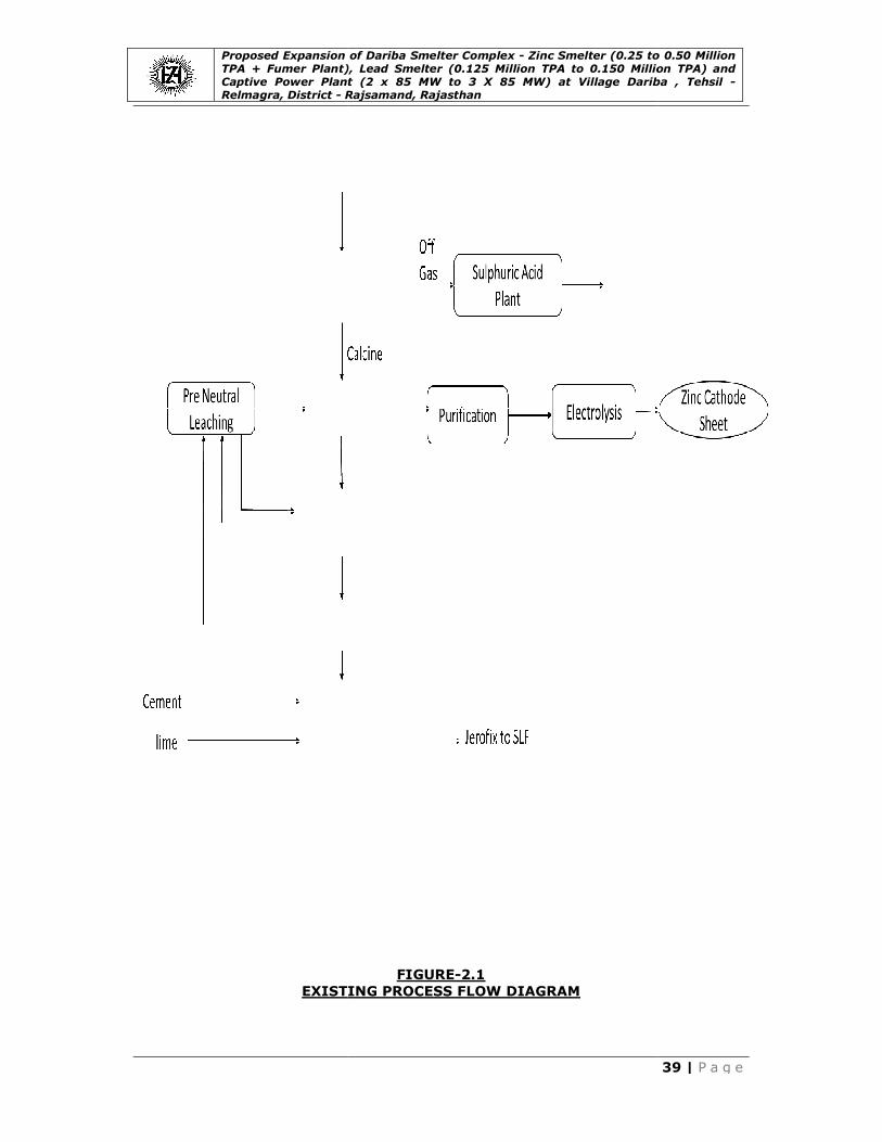
Proposed Expansion of Dariba Smelter Complex TPA + Fumer Plant), Lead Smelter (0.125 Million TPA to 0.150 Million TPA) and Captive Power Plant (2 x 85 MW to 3 X 85 MW) at Village Dariba , Relmagra, District - R
EXISTING PROCESS FLOW DIAGRAM
Proposed Expansion of Dariba Smelter Complex - Zinc Smelter (0.25 to 0.50 Million TPA + Fumer Plant), Lead Smelter (0.125 Million TPA to 0.150 Million TPA) and Captive Power Plant (2 x 85 MW to 3 X 85 MW) at Village Dariba ,
Rajsamand, Rajasthan
FIGURE-2.1
EXISTING PROCESS FLOW DIAGRAM
Zinc Smelter (0.25 to 0.50 Million TPA + Fumer Plant), Lead Smelter (0.125 Million TPA to 0.150 Million TPA) and Captive Power Plant (2 x 85 MW to 3 X 85 MW) at Village Dariba , Tehsil -
39 | P a g e

Proposed Expansion of Dariba Smelter Complex TPA + Fumer Plant), Lead Smelter (0.125 Million TPA to 0.150 Million TPA) and Captive Power Plant (2 x 85 MW to 3 X 85 MW) at Village Dariba , Relmagra, District - R
MODIFIED PROCESS FLOW DIAGRAM
Proposed Expansion of Dariba Smelter Complex - Zinc Smelter (0.25 to 0.50 Million TPA + Fumer Plant), Lead Smelter (0.125 Million TPA to 0.150 Million TPA) and Captive Power Plant (2 x 85 MW to 3 X 85 MW) at Village Dariba ,
Rajsamand, Rajasthan
FIGURE-2.2
MODIFIED PROCESS FLOW DIAGRAM
Zinc Smelter (0.25 to 0.50 Million TPA + Fumer Plant), Lead Smelter (0.125 Million TPA to 0.150 Million TPA) and Captive Power Plant (2 x 85 MW to 3 X 85 MW) at Village Dariba , Tehsil -
40 | P a g e

Proposed Expansion of Dariba Smelter Complex TPA + Fumer Plant), Lead Smelter (0.125 Million TPA to 0.150 Million TPA) and Captive Power Plant (2 x 85 MW to 3 X 85 MW) at Village Dariba , Relmagra, District - R
Lead Smelter
In line with HZL’s long term strategy of meeting India’s
decided to up our Lead
adopting the proven pyro metallurgical processing route. With the installation of
this new Lead capacity HZL’s overall primary
0.245 MTPA.
Details of Selected Process Technology
The SKS process is discussed below in the following steps
Raw Material Storage
As like any other pyro smelting technology, a robust feed storage facility is
considered for the storage of Concentrate, Coal fluxes, intermediates and
secondary’s. This will primarily consist of storage bunkers, conveyors and storage
bins for plant consumption with necessary weigh feeding arrangement. This
system will also include feed preparation facility like
SKS Smelting Furnace
The SKS smelting furnace is a horizontal cylindrical vessel with bottom blowing
capability. The furnace will be fed with feed materials from the top through feed
port and oxygen shall be blown from the bottom of the furnace. The furnace is
operated on a continuous sm
at regular intervals and cast into ingots. The bullion ingots are then transported
to the refinery for further purifications. The slag with approximately 45%
content will be cast on a cooled chain
furnace to recover balance
WHRB, Hot ESP, Wet gas cleaning facility followed by a conventional Sulphuric
acid plant.
SKS Furnace Inputs
• Mixed Feed (Fresh
Furnace Dust +Limestone + Iron Ore).
• Oxygen at 16 bar Pressure.
• Nitrogen (Only in case of Oxygen Failure) at
should be Started within
• DM water.
SKS Furnace Outputs
1. Lead Bullion (97% Purity).
2. Lead Oxidation Slag (SKS Slag)
3. SO2(~13% rich off gas).
4. SKS dust in off gas.
SKS Furnace Reactions
PbS + O2 1150°C PbO + SO
PbO + PbS 1150°C Pb + SO
Proposed Expansion of Dariba Smelter Complex - Zinc Smelter (0.25 to 0.50 Million TPA + Fumer Plant), Lead Smelter (0.125 Million TPA to 0.150 Million TPA) and Captive Power Plant (2 x 85 MW to 3 X 85 MW) at Village Dariba ,
Rajsamand, Rajasthan
In line with HZL’s long term strategy of meeting India’s Lead demand, it has been
Lead production capacity from 0.125 MTPA to 0.15 MTPA
adopting the proven pyro metallurgical processing route. With the installation of
capacity HZL’s overall primary Lead production capacity shall re
Details of Selected Process Technology
is discussed below in the following steps
Raw Material Storage
As like any other pyro smelting technology, a robust feed storage facility is
considered for the storage of Concentrate, Coal fluxes, intermediates and
. This will primarily consist of storage bunkers, conveyors and storage
bins for plant consumption with necessary weigh feeding arrangement. This
system will also include feed preparation facility like pelletizing system.
SKS Smelting Furnace
lting furnace is a horizontal cylindrical vessel with bottom blowing
capability. The furnace will be fed with feed materials from the top through feed
port and oxygen shall be blown from the bottom of the furnace. The furnace is
operated on a continuous smelting philosophy. Bullion from the furnace is tapped
at regular intervals and cast into ingots. The bullion ingots are then transported
to the refinery for further purifications. The slag with approximately 45%
content will be cast on a cooled chain conveyor which will then be fed to the blast
furnace to recover balance Lead in the slag. The off gas system shall consist of a
WHRB, Hot ESP, Wet gas cleaning facility followed by a conventional Sulphuric
(Fresh Lead Conc. + Lead Silver Complex+ SKS Dust +Blast
Furnace Dust +Limestone + Iron Ore).
bar Pressure.
(Only in case of Oxygen Failure) at 16 Bar Pressure (Nitrogen
should be Started within 15 minutes of O2 Failure).
Bullion (97% Purity).
SKS Slag)
(~13% rich off gas).
SKS Furnace Reactions
C PbO + SO2
C Pb + SO2
Zinc Smelter (0.25 to 0.50 Million TPA + Fumer Plant), Lead Smelter (0.125 Million TPA to 0.150 Million TPA) and Captive Power Plant (2 x 85 MW to 3 X 85 MW) at Village Dariba , Tehsil -
41 | P a g e
demand, it has been
to 0.15 MTPA by
adopting the proven pyro metallurgical processing route. With the installation of
production capacity shall reach
As like any other pyro smelting technology, a robust feed storage facility is
considered for the storage of Concentrate, Coal fluxes, intermediates and
. This will primarily consist of storage bunkers, conveyors and storage
bins for plant consumption with necessary weigh feeding arrangement. This
system.
lting furnace is a horizontal cylindrical vessel with bottom blowing
capability. The furnace will be fed with feed materials from the top through feed
port and oxygen shall be blown from the bottom of the furnace. The furnace is
elting philosophy. Bullion from the furnace is tapped
at regular intervals and cast into ingots. The bullion ingots are then transported
to the refinery for further purifications. The slag with approximately 45% Lead
conveyor which will then be fed to the blast
in the slag. The off gas system shall consist of a
WHRB, Hot ESP, Wet gas cleaning facility followed by a conventional Sulphuric
Silver Complex+ SKS Dust +Blast
Bar Pressure (Nitrogen

Proposed Expansion of Dariba Smelter Complex TPA + Fumer Plant), Lead Smelter (0.125 Million TPA to 0.150 Million TPA) and Captive Power Plant (2 x 85 MW to 3 X 85 MW) at Village Dariba , Relmagra, District - R
At 1150°C, Lead Sulphide reacts with Oxygen to form
oxide. The Lead Oxide in turn reacts with
and Sulphur-di-Oxide is liberated. The Heavier
of the furnace and the Slag flo
tap out the Lead bullion.
hole at the opposite side of the siphon. Sulphur forms Sulphur
escapes through Off Gas.
Off-Gas Collection
The SO2 rich Off gas with
continuously removed under the negative pressure created by an Induced Draft
Fan in the Off-Gas System. Along, with the Smelting Off Gas, air sucked from
throat and feed inlets also enters the Off gas stream. Arou
Conversion takes place in the off gas. The off gas stream passes through the
Waste Heat Recovery Boiler (WHRB) and Electro
entering the Acid Plant Battery Limit(Gas Cleaning Plant).
Almost 97.67% of sulphur fed into the furnace enters the off gas and rest being
carried in the SKS Slag.
Waste Heat Recovery Boiler
The excess heat in the Off
the Waste Heat Recovery Boiler System along with collection of off
Some of the Dust in the stream gets collected at the bottom of the Boiler which is
conveyed by a chain conveyor to the common dust chain conveyor of Dust
Collection System. This dust which is rich in
is then sent to the SKS feed Pelletiser through a weigh feeder and a Bucket
Elevator.
Electrostatic Precipitator
The Off-gas leaving the WHRB enters the Hot ESP, which is having 60 m
collection area in five fields. The discharge electrodes in the fields are charged
with high voltage and the collecting plates are neutral which collects the statically charged dust. The dust from the collecting plates is discharged by rapping system
during each cycle of operation. Dust gets collected at the bottom of the ESP,
which is conveyed by a chain conveyor to the intermediate chain conveyor. The
Off-Gas with a dust load of ~400 mg/Nm
enters the Gas cleaning section for recovery of SO
Blast Furnace
The slag from SKS furnace shall be fed to a conventional blast furnace along with
coke for recovering the
ingots and transported to the refinery for further treatment. The slag from blast furnace containing approximately 3%
holding furnace. Off-gas from the blast
Bag filter to recover dust in the off
and Bag Filter is re-cycled as they have high
Blast Furnace Inputs
1. Lead Oxidation Slag (40%
2. Limestone.
Proposed Expansion of Dariba Smelter Complex - Zinc Smelter (0.25 to 0.50 Million TPA + Fumer Plant), Lead Smelter (0.125 Million TPA to 0.150 Million TPA) and Captive Power Plant (2 x 85 MW to 3 X 85 MW) at Village Dariba ,
Rajsamand, Rajasthan
Sulphide reacts with Oxygen to form Lead Oxide and Sulphur
Oxide in turn reacts with Lead Sulphide to form pure
Oxide is liberated. The Heavier Lead bullion collects at the bottom
of the furnace and the Slag floats at the top. The Furnace has an inbuilt Siphon to
bullion. Lead Oxidation Slag is tapped out through a slag tap
hole at the opposite side of the siphon. Sulphur forms Sulphur-
escapes through Off Gas.
rich Off gas with Lead dust generated in the smelting process is
continuously removed under the negative pressure created by an Induced Draft
Gas System. Along, with the Smelting Off Gas, air sucked from
throat and feed inlets also enters the Off gas stream. Around 15 % PbS to PbO
Conversion takes place in the off gas. The off gas stream passes through the
Waste Heat Recovery Boiler (WHRB) and Electro-Static Precipitator (ESP) before
entering the Acid Plant Battery Limit(Gas Cleaning Plant).
phur fed into the furnace enters the off gas and rest being
carried in the SKS Slag.
Waste Heat Recovery Boiler
The excess heat in the Off-Gas (which is at ~1150°C) is recovered as steam in
the Waste Heat Recovery Boiler System along with collection of off
Some of the Dust in the stream gets collected at the bottom of the Boiler which is
n conveyor to the common dust chain conveyor of Dust
Collection System. This dust which is rich in Lead (~60% Pb) in the form of PbO
is then sent to the SKS feed Pelletiser through a weigh feeder and a Bucket
Electrostatic Precipitator
gas leaving the WHRB enters the Hot ESP, which is having 60 m
collection area in five fields. The discharge electrodes in the fields are charged
with high voltage and the collecting plates are neutral which collects the statically st from the collecting plates is discharged by rapping system
during each cycle of operation. Dust gets collected at the bottom of the ESP,
which is conveyed by a chain conveyor to the intermediate chain conveyor. The
Gas with a dust load of ~400 mg/Nm3 and at temperature ~350
enters the Gas cleaning section for recovery of SO2.
The slag from SKS furnace shall be fed to a conventional blast furnace along with
coke for recovering the Lead. Bullion produced from the blast furnace is cast into
ingots and transported to the refinery for further treatment. The slag from blast furnace containing approximately 3% Lead and 15% Zn is fed to the electric arc
gas from the blast furnace is treated through a Cooling Fin
Bag filter to recover dust in the off-gas. The dust collected from the Cooling Fin
cycled as they have high Lead content.
Oxidation Slag (40% Lead content).
Zinc Smelter (0.25 to 0.50 Million TPA + Fumer Plant), Lead Smelter (0.125 Million TPA to 0.150 Million TPA) and Captive Power Plant (2 x 85 MW to 3 X 85 MW) at Village Dariba , Tehsil -
42 | P a g e
Oxide and Sulphur-di-
Sulphide to form pure Lead metal
bullion collects at the bottom
ats at the top. The Furnace has an inbuilt Siphon to
Oxidation Slag is tapped out through a slag tap-
-di-oxide and
dust generated in the smelting process is
continuously removed under the negative pressure created by an Induced Draft
Gas System. Along, with the Smelting Off Gas, air sucked from
nd 15 % PbS to PbO
Conversion takes place in the off gas. The off gas stream passes through the
Static Precipitator (ESP) before
phur fed into the furnace enters the off gas and rest being
Gas (which is at ~1150°C) is recovered as steam in
the Waste Heat Recovery Boiler System along with collection of off-gas dust.
Some of the Dust in the stream gets collected at the bottom of the Boiler which is
n conveyor to the common dust chain conveyor of Dust
(~60% Pb) in the form of PbO
is then sent to the SKS feed Pelletiser through a weigh feeder and a Bucket
gas leaving the WHRB enters the Hot ESP, which is having 60 m2
collection area in five fields. The discharge electrodes in the fields are charged
with high voltage and the collecting plates are neutral which collects the statically st from the collecting plates is discharged by rapping system
during each cycle of operation. Dust gets collected at the bottom of the ESP,
which is conveyed by a chain conveyor to the intermediate chain conveyor. The
and at temperature ~350°C then
The slag from SKS furnace shall be fed to a conventional blast furnace along with
. Bullion produced from the blast furnace is cast into
ingots and transported to the refinery for further treatment. The slag from blast and 15% Zn is fed to the electric arc
furnace is treated through a Cooling Fin
gas. The dust collected from the Cooling Fin

Proposed Expansion of Dariba Smelter Complex TPA + Fumer Plant), Lead Smelter (0.125 Million TPA to 0.150 Million TPA) and Captive Power Plant (2 x 85 MW to 3 X 85 MW) at Village Dariba , Relmagra, District - R
3. Coke
4. Air Blast from Blower House
5. Lean Slag from Noble
Blast Furnace Outputs
1. Lead Bullion(97 % purity).
2. Blast Furnace Slag.
3. Blast Furnace Dust.
Blast Furnace Reactions
PbO + C
Reduction
Off-Gas Dust Collection Section
The off-gas from blast furnace passes through the cooling flue (Surface Cooler)
and bag filter and then will be sent to
Draft Fan located at the Outlet of the Bag filter keeps the negative pressure in
operation for off gas flow from Blast furnace through Cooling flue and Bag Filter. The Dust load of the off gas is ~10.69
There are 3 sets of 900
installed on the inlet of cooling flue. When Off
this valve will automatically open for diluting the off gas with cold air. When
temperature becomes less than 100°C, it will automatically close. The Duct
between blast furnace and cooling flue is designed as up
avoid dust accumulation.
A cooling water jacket is equipped on the outlet pipe of the Blast furnace. When
the off-gas temperature is higher than the design value, the water feed system
will turn on automatically for cold water charging.
After the cooling Flue, the gas enters a Bag filter of collection area 2400m
bag filter is waterproof and covered with t
bag filter is designed to meet the gas emission requirements. Explosion valves
are equipped on the bag filter for safe operation as the off gas from blast furnace
contains good amount of CO (refer equation).
The Dust collected in the cooling flue and Bag Filter are conveyed to the
Dust receiving bin located at SKS furnace workshop through a Pneumatic
Conveying System. This Pneumatic conveying system uses compressed nitrogen
from the oxygen plant for SKS furnace.
Slag Fuming Furnace
The blast furnace slag is first taken to the electric arc furnace to maintain the
temperature of the slag and also to buffer a stock of slag for one batch of slag
fuming furnace operation. The slag fuming is done on batch processing
philosophy by using pulverized coal along with high pressure air. The final slag
produced after fuming is
applications. The off-gas system is designed to recover Waste heat through
WHRB. Zinc Oxide compound (with ~10 to 20%
Proposed Expansion of Dariba Smelter Complex - Zinc Smelter (0.25 to 0.50 Million TPA + Fumer Plant), Lead Smelter (0.125 Million TPA to 0.150 Million TPA) and Captive Power Plant (2 x 85 MW to 3 X 85 MW) at Village Dariba ,
Rajsamand, Rajasthan
4. Air Blast from Blower House.
5. Lean Slag from Noble Lead Furnace.
Blast Furnace Outputs
Bullion(97 % purity).
Blast Furnace Reactions
PbO + C Pb + CO + CO2
Reduction
Gas Dust Collection Section
gas from blast furnace passes through the cooling flue (Surface Cooler)
and bag filter and then will be sent to the Tail-gas Scrubbing section. The Induced
Draft Fan located at the Outlet of the Bag filter keeps the negative pressure in
operation for off gas flow from Blast furnace through Cooling flue and Bag Filter. The Dust load of the off gas is ~10.69 g/m3.
m2 cooling flues for the Dust Collection. A cold air valve is
installed on the inlet of cooling flue. When Off-gas temperature is above 170°C,
this valve will automatically open for diluting the off gas with cold air. When
re becomes less than 100°C, it will automatically close. The Duct
between blast furnace and cooling flue is designed as up-side-down ‘V’ shaped to
avoid dust accumulation.
A cooling water jacket is equipped on the outlet pipe of the Blast furnace. When
gas temperature is higher than the design value, the water feed system
will turn on automatically for cold water charging.
After the cooling Flue, the gas enters a Bag filter of collection area 2400m
bag filter is waterproof and covered with temperature resistant materials. The
bag filter is designed to meet the gas emission requirements. Explosion valves
are equipped on the bag filter for safe operation as the off gas from blast furnace
contains good amount of CO (refer equation).
llected in the cooling flue and Bag Filter are conveyed to the
Dust receiving bin located at SKS furnace workshop through a Pneumatic
Conveying System. This Pneumatic conveying system uses compressed nitrogen
from the oxygen plant for SKS furnace.
The blast furnace slag is first taken to the electric arc furnace to maintain the
temperature of the slag and also to buffer a stock of slag for one batch of slag
fuming furnace operation. The slag fuming is done on batch processing
ilosophy by using pulverized coal along with high pressure air. The final slag
produced after fuming is discard able quality with huge potential for downstream
gas system is designed to recover Waste heat through
Oxide compound (with ~10 to 20% Lead and ~55% Zinc
Zinc Smelter (0.25 to 0.50 Million TPA + Fumer Plant), Lead Smelter (0.125 Million TPA to 0.150 Million TPA) and Captive Power Plant (2 x 85 MW to 3 X 85 MW) at Village Dariba , Tehsil -
43 | P a g e
gas from blast furnace passes through the cooling flue (Surface Cooler)
gas Scrubbing section. The Induced
Draft Fan located at the Outlet of the Bag filter keeps the negative pressure in
operation for off gas flow from Blast furnace through Cooling flue and Bag Filter.
cooling flues for the Dust Collection. A cold air valve is
gas temperature is above 170°C,
this valve will automatically open for diluting the off gas with cold air. When
re becomes less than 100°C, it will automatically close. The Duct
down ‘V’ shaped to
A cooling water jacket is equipped on the outlet pipe of the Blast furnace. When
gas temperature is higher than the design value, the water feed system
After the cooling Flue, the gas enters a Bag filter of collection area 2400m2. The
emperature resistant materials. The
bag filter is designed to meet the gas emission requirements. Explosion valves
are equipped on the bag filter for safe operation as the off gas from blast furnace
llected in the cooling flue and Bag Filter are conveyed to the Lead
Dust receiving bin located at SKS furnace workshop through a Pneumatic
Conveying System. This Pneumatic conveying system uses compressed nitrogen
The blast furnace slag is first taken to the electric arc furnace to maintain the
temperature of the slag and also to buffer a stock of slag for one batch of slag
fuming furnace operation. The slag fuming is done on batch processing
ilosophy by using pulverized coal along with high pressure air. The final slag
quality with huge potential for downstream
gas system is designed to recover Waste heat through
Zinc) in the off

Proposed Expansion of Dariba Smelter Complex TPA + Fumer Plant), Lead Smelter (0.125 Million TPA to 0.150 Million TPA) and Captive Power Plant (2 x 85 MW to 3 X 85 MW) at Village Dariba , Relmagra, District - R
gas shall be recovered from WHRB and Bag Filter system. The
utilized in the Leaching section of
Fuming Furnace Inputs
1. Blast Furnace Slag.
2. Pulverized Coal (fed to furnace by Air Blast Stream).
3. Blast Air (from Blower House).
Fuming Furnace Outputs
1. ZnO Fume.
2. Fuming Furnace Slag.
Discard Slag
The slag tapped from the fuming furnace will have ~0.5% of Pb and ~2.5% of
Zn. This slag is not viable for further recovery of metals and hence shall be
discarded. The slag is tapped and granulated by a jet of water in slag launder.
After water Granulation and Settlement, the Slag will be grabbed by bridge crane
and is stored in Slag Bin. From strucks.
Off-Gas Collection System
The Off-Gas generated is sucked by an Induced Draft Fan located at the Outlet of
the Bag filter and the fan keeps the negative pressure in operation. The off
passes through the WHRB and the temperature of off
enters the cooling flue (Surface Cooler) and bag filter where the
collected. The off gas leaving the bag filter will be sent to Tail gas Scrubbing unit.
The Dust load of the Off gas is ~79g/m
The dust collection in fuming furnace is similar to the dusBlast furnace section. The
collected in the cooling flue and Bag Filter are conveyed to the Intermediate
storage bin by chain conveyors. From the bin, the dust is collected and bagged in
nylon bags by bagging machine of capacity 10
stored in Zinc Oxide Storage building and before being sent for recovery of
Lead.
Coal Pulverization Plant
The Off-gas from pulverized Coal Combustion in the firebox is sent
through the spark catcher and after feeding with Cold Air. The Output of Coal mill
is classified by the separator to separate the large
back to coal mill) and fine granules enter the cyclone separator and Blow
filter which collect fine dust(sent to Intermediate Silo).
of Lead Smelter is shown in
Lead Refinery
The Lead refining section consists of the following three main
1. Copper De-drossing and Anode 2. Cell House 3. Cathode Preparation / Melting & Ingot Casting Section
Proposed Expansion of Dariba Smelter Complex - Zinc Smelter (0.25 to 0.50 Million TPA + Fumer Plant), Lead Smelter (0.125 Million TPA to 0.150 Million TPA) and Captive Power Plant (2 x 85 MW to 3 X 85 MW) at Village Dariba ,
Rajsamand, Rajasthan
gas shall be recovered from WHRB and Bag Filter system. The Zinc Oxide shall be
utilized in the Leaching section of ZincSmelter or in the Pyro Smelter.
Fuming Furnace Inputs
lag.
Pulverized Coal (fed to furnace by Air Blast Stream).
Blast Air (from Blower House).
Fuming Furnace Outputs
Fuming Furnace Slag.
The slag tapped from the fuming furnace will have ~0.5% of Pb and ~2.5% of
not viable for further recovery of metals and hence shall be
discarded. The slag is tapped and granulated by a jet of water in slag launder.
After water Granulation and Settlement, the Slag will be grabbed by bridge crane
nd is stored in Slag Bin. From slag bin, the slag is transported to s
Gas Collection System
Gas generated is sucked by an Induced Draft Fan located at the Outlet of
the Bag filter and the fan keeps the negative pressure in operation. The off
passes through the WHRB and the temperature of off-gas drops to 360°C.Then it
ng flue (Surface Cooler) and bag filter where the Zinc
collected. The off gas leaving the bag filter will be sent to Tail gas Scrubbing unit.
The Dust load of the Off gas is ~79g/m3.
The dust collection in fuming furnace is similar to the dust collection system of Blast furnace section. The Zinc oxide compound (~55% Zn, 10~20% Pb)
collected in the cooling flue and Bag Filter are conveyed to the Intermediate
storage bin by chain conveyors. From the bin, the dust is collected and bagged in
bags by bagging machine of capacity 10-40 bags/hour. The Bags are then
Oxide Storage building and before being sent for recovery of
Coal Pulverization Plant
gas from pulverized Coal Combustion in the firebox is sent to the coal mill
through the spark catcher and after feeding with Cold Air. The Output of Coal mill
is classified by the separator to separate the large-size granules (which are sent
back to coal mill) and fine granules enter the cyclone separator and Blow
filter which collect fine dust(sent to Intermediate Silo). The process block diagram
is shown in Figure 2.3.
refining section consists of the following three main sub-sections
drossing and Anode Fabrication.
Cathode Preparation / Melting & Ingot Casting Section
Zinc Smelter (0.25 to 0.50 Million TPA + Fumer Plant), Lead Smelter (0.125 Million TPA to 0.150 Million TPA) and Captive Power Plant (2 x 85 MW to 3 X 85 MW) at Village Dariba , Tehsil -
44 | P a g e
Oxide shall be
.
The slag tapped from the fuming furnace will have ~0.5% of Pb and ~2.5% of
not viable for further recovery of metals and hence shall be
discarded. The slag is tapped and granulated by a jet of water in slag launder.
After water Granulation and Settlement, the Slag will be grabbed by bridge crane
in, the slag is transported to slag yard by
Gas generated is sucked by an Induced Draft Fan located at the Outlet of
the Bag filter and the fan keeps the negative pressure in operation. The off-gas
gas drops to 360°C.Then it
Zinc rich dust is
collected. The off gas leaving the bag filter will be sent to Tail gas Scrubbing unit.
t collection system of oxide compound (~55% Zn, 10~20% Pb)
collected in the cooling flue and Bag Filter are conveyed to the Intermediate
storage bin by chain conveyors. From the bin, the dust is collected and bagged in
40 bags/hour. The Bags are then
Oxide Storage building and before being sent for recovery of Zinc &
to the coal mill
through the spark catcher and after feeding with Cold Air. The Output of Coal mill
size granules (which are sent
back to coal mill) and fine granules enter the cyclone separator and Blowback Bag
The process block diagram
sections

Proposed Expansion of Dariba Smelter Complex TPA + Fumer Plant), Lead Smelter (0.125 Million TPA to 0.150 Million TPA) and Captive Power Plant (2 x 85 MW to 3 X 85 MW) at Village Dariba , Relmagra, District - R
The cast bullion produced from SKS & Blast furnace is transported to the
electrolytic refinery for melting and drossing to remove copper from the bullion.
After copper drossing,
electro refining. The initial thin cathode sheets are produced from refined
and the final thick cathodes produced from the electro
removed on periodical basis for melting and
slime from the electro
valuable metals like silver, antimony, Bismuth etc.
Silver Refinery
The proposed plant shall have Rotary furnaces like Noble
furnace to produce silver bullion. The antimony and bismuth concentrate shall be
recovered from the off-
Fins and Bag Filter. The bismuth concentrate is skimmed from the Cupel furnace.
Lead rich slag (recyclable) and copper matte (saleable) is also recovered from the
Cupel furnace. The silver bullion is further refined by electrolysis. The pure silver
powder from the electrolytic process is melted and casted into silver ingot of
99.99% purity.
Copper Recovery Plant
The proposed plant will take the copper dross from the electro
will produce copper matte of around 40% purity. This plant uses the ball mill and
rever beratory furnaces to produce the copper matte. Copper matte shall
Off-Gas Collection
The Off-Gas having little content of sulphur as SO
chamber and bag filter system under negative pressure created by induced draft
fan and finally sent to Tail gas treatment plant. The
flue chamber and in turn, the inlet air for the burner of Rever
preheated. The dust is collected in the bag filter and is sent back to SKS Furnace.
PROCESS FLOW DIAGRAM
Blast Furnace
Acid Plant
Scrubber
Off-Gas
Off-Gas
Sulphuric Acid
Stack
Tail Gas
Lead
Conc.
Secondary
Proposed Expansion of Dariba Smelter Complex - Zinc Smelter (0.25 to 0.50 Million TPA + Fumer Plant), Lead Smelter (0.125 Million TPA to 0.150 Million TPA) and Captive Power Plant (2 x 85 MW to 3 X 85 MW) at Village Dariba ,
Rajsamand, Rajasthan
The cast bullion produced from SKS & Blast furnace is transported to the
electrolytic refinery for melting and drossing to remove copper from the bullion.
the Lead bullion is cast into anode forms suitable for
electro refining. The initial thin cathode sheets are produced from refined
and the final thick cathodes produced from the electro-refining process are
removed on periodical basis for melting and casting into saleable ingots. The
slime from the electro-refining operation is further treated for recovery of
valuable metals like silver, antimony, Bismuth etc.
The proposed plant shall have Rotary furnaces like Noble Lead furnace &
furnace to produce silver bullion. The antimony and bismuth concentrate shall be
-gas handling system of the furnaces which has Cooling
Fins and Bag Filter. The bismuth concentrate is skimmed from the Cupel furnace.
ag (recyclable) and copper matte (saleable) is also recovered from the
Cupel furnace. The silver bullion is further refined by electrolysis. The pure silver
powder from the electrolytic process is melted and casted into silver ingot of
per Recovery Plant
The proposed plant will take the copper dross from the electro-refinery plant and
will produce copper matte of around 40% purity. This plant uses the ball mill and
beratory furnaces to produce the copper matte. Copper matte shall
Gas Collection
Gas having little content of sulphur as SO2 passes through a flue gas
chamber and bag filter system under negative pressure created by induced draft
fan and finally sent to Tail gas treatment plant. The hot off-gas is cooled in the
flue chamber and in turn, the inlet air for the burner of Rever beratory furnace is
preheated. The dust is collected in the bag filter and is sent back to SKS Furnace.
FIGURE-2.3
PROCESS FLOW DIAGRAM – LEAD SMELTER
SKS Furnace
Blast Furnace
Fuming
Furnace
Refinery Plant
Lead Anode
Slilme/silver
BismuthCopper
Low Lead Slag
Discard Slag
High Lead Slag
Bullion
Bullion
Zinc Oxide
Compound
Antimony
Conc.
Lead Silver compoun
**
Flux Re-Cycle
*
Secondary
* - Re-Cyc
**- By-Product from Zinc Smelter
Zinc Smelter (0.25 to 0.50 Million TPA + Fumer Plant), Lead Smelter (0.125 Million TPA to 0.150 Million TPA) and Captive Power Plant (2 x 85 MW to 3 X 85 MW) at Village Dariba , Tehsil -
45 | P a g e
The cast bullion produced from SKS & Blast furnace is transported to the
electrolytic refinery for melting and drossing to remove copper from the bullion.
bullion is cast into anode forms suitable for
electro refining. The initial thin cathode sheets are produced from refined Lead
refining process are
casting into saleable ingots. The
refining operation is further treated for recovery of
furnace & Cupel
furnace to produce silver bullion. The antimony and bismuth concentrate shall be
gas handling system of the furnaces which has Cooling
Fins and Bag Filter. The bismuth concentrate is skimmed from the Cupel furnace.
ag (recyclable) and copper matte (saleable) is also recovered from the
Cupel furnace. The silver bullion is further refined by electrolysis. The pure silver
powder from the electrolytic process is melted and casted into silver ingot of
refinery plant and
will produce copper matte of around 40% purity. This plant uses the ball mill and
beratory furnaces to produce the copper matte. Copper matte shall be sold.
passes through a flue gas
chamber and bag filter system under negative pressure created by induced draft
gas is cooled in the
beratory furnace is
preheated. The dust is collected in the bag filter and is sent back to SKS Furnace.
Bismuth
Antimony
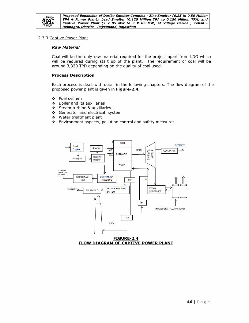
Proposed Expansion of Dariba Smelter Complex TPA + Fumer Plant), Lead Smelter (0.125 Million TPA to 0.150 Million TPA) and Captive Power Plant (2 x 85 MW to 3 X 85 MW) at Village Dariba , Relmagra, District - R
2.3.3 Captive Power Plant
Raw Material
Coal will be the only raw material required for the project apart from LDO which
will be required during start up of the plant.
around 3,320 TPD depending on the quality of coal used.
Process Description
Each process is dealt with detail in the following chapters.
proposed power plant is given in
� Fuel system
� Boiler and its auxiliaries
� Steam turbine & auxiliaries
� Generator and electrical system
� Water treatment plant
� Environment aspects, pollution control and safety measures
FLOW DIAGRAM
Proposed Expansion of Dariba Smelter Complex - Zinc Smelter (0.25 to 0.50 Million TPA + Fumer Plant), Lead Smelter (0.125 Million TPA to 0.150 Million TPA) and Captive Power Plant (2 x 85 MW to 3 X 85 MW) at Village Dariba ,
Rajsamand, Rajasthan
Coal will be the only raw material required for the project apart from LDO which
will be required during start up of the plant. The requirement of coal will be
320 TPD depending on the quality of coal used.
Each process is dealt with detail in the following chapters. The flow diagram of the
proposed power plant is given in Figure-2.4.
Boiler and its auxiliaries
& auxiliaries
Generator and electrical system
Water treatment plant
Environment aspects, pollution control and safety measures
FIGURE-2.4
DIAGRAM OF CAPTIVE POWER PLANT
Zinc Smelter (0.25 to 0.50 Million TPA + Fumer Plant), Lead Smelter (0.125 Million TPA to 0.150 Million TPA) and Captive Power Plant (2 x 85 MW to 3 X 85 MW) at Village Dariba , Tehsil -
46 | P a g e
Coal will be the only raw material required for the project apart from LDO which
The requirement of coal will be
The flow diagram of the
Proposed Expansion of Dariba Smelter Complex TPA + Fumer Plant), Lead Smelter (0.125 Million TPA to 0.150 Million TPA) and Captive Power Plant (2 x 85 MW to 3 X 85 MW) at Village Dariba , Relmagra, District - R
Fuel System
As coal is the prime fuel for a thermal power plant, adequate emphasis needs to
be given for its proper handling and storage. It is also important to have a
sustained flow of the fuel to maintain uninterrupted power generation. The
capacity of the coal sto
will be of capacity about 220 TPH for each unit. However, the conveying rate
depends on the gross calorific value of the fuel used.
Coal Bunkers
These are in-process storage silos used for storing
the coal handling system. These will be made up of welded steel plates with
vibrating arrangement at the outlet to avoid choking of coal. For each mill there
will be a bunker and all together there will be four bunkers for two cr
which will be fed through gravimetric feeders. These bunkers present on top of
the mill to aid in gravity feeding of coal to the mills.
Coal Conveying System
This section deals with two primary aspects of preparation and firing of coal in detail. The coal preparation equipment viz. feeders and mills, firing systems and
the firing equipment viz. the burners and their arrangement are described here
under.
Feeders
In most of the power stations, the types of feeders used for transportation of coal
from bunker to the mills are
� Drag chain feeders
� Belt feeders
� Table type rotary feeders� Gravimetric type of feeders
Mills
Pulverized fuel firing is a method whereby the
fineness such that 70-80% passes through a 200 mesh sieve, is carried forward
pneumatically directly to burners or storage bins from where it is passed into
burners. When discharged into combustion chamber, the mixture of
ignites and burns in fluidized state.
The economic motives for the introduction and development of pulverized fuel
firing are:
� Efficient utilization of low grade coals
� Flexibility in firing with ability to meet fluctuating loads
� Elimination of banking losses
� Better reaction to automatic control
� Ability to use high combustion air temperature increasing the overall
efficiency of boiler
� Better availability
Proposed Expansion of Dariba Smelter Complex - Zinc Smelter (0.25 to 0.50 Million TPA + Fumer Plant), Lead Smelter (0.125 Million TPA to 0.150 Million TPA) and Captive Power Plant (2 x 85 MW to 3 X 85 MW) at Village Dariba ,
Rajsamand, Rajasthan
As coal is the prime fuel for a thermal power plant, adequate emphasis needs to
be given for its proper handling and storage. It is also important to have a
sustained flow of the fuel to maintain uninterrupted power generation. The
rage for proposed CPP is 45,000 ton. The conveyor belts
will be of capacity about 220 TPH for each unit. However, the conveying rate
depends on the gross calorific value of the fuel used.
process storage silos used for storing crushed coal conveyed from
the coal handling system. These will be made up of welded steel plates with
vibrating arrangement at the outlet to avoid choking of coal. For each mill there
will be a bunker and all together there will be four bunkers for two cr
which will be fed through gravimetric feeders. These bunkers present on top of
the mill to aid in gravity feeding of coal to the mills.
Coal Conveying System
This section deals with two primary aspects of preparation and firing of coal in etail. The coal preparation equipment viz. feeders and mills, firing systems and
the firing equipment viz. the burners and their arrangement are described here
In most of the power stations, the types of feeders used for transportation of coal
from bunker to the mills are
Table type rotary feeders Gravimetric type of feeders
Pulverized fuel firing is a method whereby the crushed coal, generally reduced to
80% passes through a 200 mesh sieve, is carried forward
pneumatically directly to burners or storage bins from where it is passed into
burners. When discharged into combustion chamber, the mixture of
ignites and burns in fluidized state.
The economic motives for the introduction and development of pulverized fuel
Efficient utilization of low grade coals
Flexibility in firing with ability to meet fluctuating loads
of banking losses
Better reaction to automatic control
Ability to use high combustion air temperature increasing the overall
Zinc Smelter (0.25 to 0.50 Million TPA + Fumer Plant), Lead Smelter (0.125 Million TPA to 0.150 Million TPA) and Captive Power Plant (2 x 85 MW to 3 X 85 MW) at Village Dariba , Tehsil -
47 | P a g e
As coal is the prime fuel for a thermal power plant, adequate emphasis needs to
be given for its proper handling and storage. It is also important to have a
sustained flow of the fuel to maintain uninterrupted power generation. The
000 ton. The conveyor belts
will be of capacity about 220 TPH for each unit. However, the conveying rate
crushed coal conveyed from
the coal handling system. These will be made up of welded steel plates with
vibrating arrangement at the outlet to avoid choking of coal. For each mill there
will be a bunker and all together there will be four bunkers for two crushing units,
which will be fed through gravimetric feeders. These bunkers present on top of
This section deals with two primary aspects of preparation and firing of coal in etail. The coal preparation equipment viz. feeders and mills, firing systems and
the firing equipment viz. the burners and their arrangement are described here
In most of the power stations, the types of feeders used for transportation of coal
crushed coal, generally reduced to
80% passes through a 200 mesh sieve, is carried forward
pneumatically directly to burners or storage bins from where it is passed into
burners. When discharged into combustion chamber, the mixture of air and coal
The economic motives for the introduction and development of pulverized fuel
Ability to use high combustion air temperature increasing the overall

Proposed Expansion of Dariba Smelter Complex TPA + Fumer Plant), Lead Smelter (0.125 Million TPA to 0.150 Million TPA) and Captive Power Plant (2 x 85 MW to 3 X 85 MW) at Village Dariba , Relmagra, District - R
Even though the high capital cost is involved, the pulverized system is proposed
due to the above mentioned advantages.
Pulverizers
Milling plant is divided into three main types
having its own advantages and drawbacks. In proposed CPP the mills will be of
bowl mill type and will be operated at medium
Pulverized Coal Conveying System
The system for direct firing of pulverized coal utilizes bowl mills to pulverize the
coal and to admit the pulverized coal together with the air required for
combustion (secondary air) to the furnace. As crushed
its feeder, primary air is supplied from the primary air fans, which dries the coal
as it is being pulverized and transports the pulverized coal through the coal piping
system to the coal nozzles in the wind box assemblies. The
air discharged from the coal nozzles is directed towards the center of the furnace
to form a fire ball. Fully preheated secondary air for combustion enters the
furnace around the pulverized coal nozzles and through the auxiliary air
compartments directly adjacent to the coal nozzle compartments. The pulverized coal and air streams entering the furnace are initially ignited by a suitable ignition
source at nozzle exit. Above a predictable minimum loading condition the ignition
becomes self sustaining. Combustion is completed as the gases spiral up in the
furnace.
Air and Draft System
The air we need for combustion in the furnace and the flue gas that we must
evacuate would not be possible without using fans. A fan is capable of imparting
energy to the air/gas in the form of a boost in pressure. The losses through the
system are overcome by means of this pressure boost. The boost is dependent on
density for a given fan at a given speed. The higher the temperature, the lower is the boost. Fan performance (maximum capability) is represented as volume Vs
pressure boost. The basic information needed to select a fan is:
1) Air or gas flow
2) Density (as a function of temperature and pressure)
3) System resistance (losses)
Classification of fans
In boiler practice, we come across the following fans
Draft system
The term ‘draft’ refers to the difference between the atmospheric pressure and
the pressure in the furnace. Depending upon the draft used, we have
� Natural draft
� Induced draft
� Forced draft
� Balanced draft
Proposed Expansion of Dariba Smelter Complex - Zinc Smelter (0.25 to 0.50 Million TPA + Fumer Plant), Lead Smelter (0.125 Million TPA to 0.150 Million TPA) and Captive Power Plant (2 x 85 MW to 3 X 85 MW) at Village Dariba ,
Rajsamand, Rajasthan
Even though the high capital cost is involved, the pulverized system is proposed
the above mentioned advantages.
Milling plant is divided into three main types- low, medium and high speed; each
having its own advantages and drawbacks. In proposed CPP the mills will be of
bowl mill type and will be operated at medium speed.
Pulverized Coal Conveying System
The system for direct firing of pulverized coal utilizes bowl mills to pulverize the
coal and to admit the pulverized coal together with the air required for
combustion (secondary air) to the furnace. As crushed coal is fed to each mill by
its feeder, primary air is supplied from the primary air fans, which dries the coal
as it is being pulverized and transports the pulverized coal through the coal piping
system to the coal nozzles in the wind box assemblies. The pulverized coal and
air discharged from the coal nozzles is directed towards the center of the furnace
to form a fire ball. Fully preheated secondary air for combustion enters the
furnace around the pulverized coal nozzles and through the auxiliary air
partments directly adjacent to the coal nozzle compartments. The pulverized coal and air streams entering the furnace are initially ignited by a suitable ignition
source at nozzle exit. Above a predictable minimum loading condition the ignition
f sustaining. Combustion is completed as the gases spiral up in the
The air we need for combustion in the furnace and the flue gas that we must
evacuate would not be possible without using fans. A fan is capable of imparting
energy to the air/gas in the form of a boost in pressure. The losses through the
system are overcome by means of this pressure boost. The boost is dependent on
density for a given fan at a given speed. The higher the temperature, the lower is an performance (maximum capability) is represented as volume Vs
pressure boost. The basic information needed to select a fan is:
2) Density (as a function of temperature and pressure)
3) System resistance (losses)
In boiler practice, we come across the following fans
The term ‘draft’ refers to the difference between the atmospheric pressure and
the pressure in the furnace. Depending upon the draft used, we have
Zinc Smelter (0.25 to 0.50 Million TPA + Fumer Plant), Lead Smelter (0.125 Million TPA to 0.150 Million TPA) and Captive Power Plant (2 x 85 MW to 3 X 85 MW) at Village Dariba , Tehsil -
48 | P a g e
Even though the high capital cost is involved, the pulverized system is proposed
low, medium and high speed; each
having its own advantages and drawbacks. In proposed CPP the mills will be of
The system for direct firing of pulverized coal utilizes bowl mills to pulverize the
coal and to admit the pulverized coal together with the air required for
coal is fed to each mill by
its feeder, primary air is supplied from the primary air fans, which dries the coal
as it is being pulverized and transports the pulverized coal through the coal piping
pulverized coal and
air discharged from the coal nozzles is directed towards the center of the furnace
to form a fire ball. Fully preheated secondary air for combustion enters the
furnace around the pulverized coal nozzles and through the auxiliary air
partments directly adjacent to the coal nozzle compartments. The pulverized coal and air streams entering the furnace are initially ignited by a suitable ignition
source at nozzle exit. Above a predictable minimum loading condition the ignition
f sustaining. Combustion is completed as the gases spiral up in the
The air we need for combustion in the furnace and the flue gas that we must
evacuate would not be possible without using fans. A fan is capable of imparting
energy to the air/gas in the form of a boost in pressure. The losses through the
system are overcome by means of this pressure boost. The boost is dependent on
density for a given fan at a given speed. The higher the temperature, the lower is an performance (maximum capability) is represented as volume Vs
The term ‘draft’ refers to the difference between the atmospheric pressure and
the pressure in the furnace. Depending upon the draft used, we have

Proposed Expansion of Dariba Smelter Complex TPA + Fumer Plant), Lead Smelter (0.125 Million TPA to 0.150 Million TPA) and Captive Power Plant (2 x 85 MW to 3 X 85 MW) at Village Dariba , Relmagra, District - R
Air Heaters
Air heater uses a heat transfer surface in which air temperature is raised by
transferring heat from other fluids such as flue gas. Since air heater can be
successfully employed to reclaim heat from the flue gas
than is possible with economizer, the heat rejected to chimney can be reduced to
higher extent thus increasing the efficiency of the boiler. For every 20
flue gas exit temperature, the boiler efficiency increases by abou
Boiler and its Auxiliaries
A boiler is a device for generating steam for power, processing or heating
purposes. Boilers are designed to transmit heat from an external combustion
source (usually fuel combustion to fluid) contained within the boiler
heat generating unit includes a furnace in which the fuel is burned. With the
advent of water cooled furnace walls, super heaters, air pre
economizer, the term ‘steam generator’ was evolved as a better description of the
apparatus.
Boilers may be classified on the basis of use, pressure, materials, size, tube
content, tube shape and position, firing, heat source, fuel, fluid, circulations, furnace position, furnace type, general shape and other special features. As the
unit is primarily for power generation it is known as control station steam
generator or utility plants.
The boiler used in proposed
natural circulated bi-drum, dry bottom type unit. Each corner of the boiler is fit
with tangential burner boxes comprising of two high energy arc ignitors, two light
oil fired burners and four pulverized coal burners. The boiler is an external
combustion device in that the combustion takes place outside the region of
boiling water. A boiler furnace is that space under or adjacent to a boiler in which
fuel is burnt and from which the combustion products pass into the boiler. It
provides a chamber in which the combustion reaction can be isolated and confined so that the reaction remains
support or enclosure for the firing equipment.
Fuel Firing System
Fuel firing can be classified as direct firing system and indirect firing or
intermediate bunker system. Both the systems can use any type of
proposed expansion power plant direct firing of coal will be employed and hot gas
will be used for drying and transporting the coal in the form of primary air.
Tangential Firing
Tangential firing will be employed in the furnace here. In this system, burners are
set at each corner of the furnace and are directed to strike the outside of an
imaginary circle in the centre of the furnace. Because, the streams of the fuel so
strike each other, extremely good mixing is obtained. Since the body of the flame
produced is given a rotary motion it
spread out and fill the combustion chamber.
Proposed Expansion of Dariba Smelter Complex - Zinc Smelter (0.25 to 0.50 Million TPA + Fumer Plant), Lead Smelter (0.125 Million TPA to 0.150 Million TPA) and Captive Power Plant (2 x 85 MW to 3 X 85 MW) at Village Dariba ,
Rajsamand, Rajasthan
Air heater uses a heat transfer surface in which air temperature is raised by
transferring heat from other fluids such as flue gas. Since air heater can be
successfully employed to reclaim heat from the flue gas at low temperature levels
than is possible with economizer, the heat rejected to chimney can be reduced to
higher extent thus increasing the efficiency of the boiler. For every 20
flue gas exit temperature, the boiler efficiency increases by about 1%.
Boiler and its Auxiliaries
A boiler is a device for generating steam for power, processing or heating
purposes. Boilers are designed to transmit heat from an external combustion
source (usually fuel combustion to fluid) contained within the boiler
heat generating unit includes a furnace in which the fuel is burned. With the
advent of water cooled furnace walls, super heaters, air pre
economizer, the term ‘steam generator’ was evolved as a better description of the
Boilers may be classified on the basis of use, pressure, materials, size, tube
content, tube shape and position, firing, heat source, fuel, fluid, circulations, furnace position, furnace type, general shape and other special features. As the
ily for power generation it is known as control station steam
generator or utility plants.
The boiler used in proposed expansion power plant will be a radiant, n
drum, dry bottom type unit. Each corner of the boiler is fit
with tangential burner boxes comprising of two high energy arc ignitors, two light
oil fired burners and four pulverized coal burners. The boiler is an external
combustion device in that the combustion takes place outside the region of
boiler furnace is that space under or adjacent to a boiler in which
fuel is burnt and from which the combustion products pass into the boiler. It
provides a chamber in which the combustion reaction can be isolated and confined so that the reaction remains a controlled force. In addition, it provides
support or enclosure for the firing equipment.
Fuel firing can be classified as direct firing system and indirect firing or
intermediate bunker system. Both the systems can use any type of
power plant direct firing of coal will be employed and hot gas
will be used for drying and transporting the coal in the form of primary air.
Tangential firing will be employed in the furnace here. In this system, burners are
set at each corner of the furnace and are directed to strike the outside of an
imaginary circle in the centre of the furnace. Because, the streams of the fuel so
h other, extremely good mixing is obtained. Since the body of the flame
produced is given a rotary motion it leads to a longer flame travel and the gases
spread out and fill the combustion chamber.
Zinc Smelter (0.25 to 0.50 Million TPA + Fumer Plant), Lead Smelter (0.125 Million TPA to 0.150 Million TPA) and Captive Power Plant (2 x 85 MW to 3 X 85 MW) at Village Dariba , Tehsil -
49 | P a g e
Air heater uses a heat transfer surface in which air temperature is raised by
transferring heat from other fluids such as flue gas. Since air heater can be
at low temperature levels
than is possible with economizer, the heat rejected to chimney can be reduced to
higher extent thus increasing the efficiency of the boiler. For every 20oC drop in
t 1%.
A boiler is a device for generating steam for power, processing or heating
purposes. Boilers are designed to transmit heat from an external combustion
source (usually fuel combustion to fluid) contained within the boiler itself. The
heat generating unit includes a furnace in which the fuel is burned. With the
advent of water cooled furnace walls, super heaters, air pre-heater and
economizer, the term ‘steam generator’ was evolved as a better description of the
Boilers may be classified on the basis of use, pressure, materials, size, tube
content, tube shape and position, firing, heat source, fuel, fluid, circulations, furnace position, furnace type, general shape and other special features. As the
ily for power generation it is known as control station steam
power plant will be a radiant, non reheat,
drum, dry bottom type unit. Each corner of the boiler is fitted
with tangential burner boxes comprising of two high energy arc ignitors, two light
oil fired burners and four pulverized coal burners. The boiler is an external
combustion device in that the combustion takes place outside the region of
boiler furnace is that space under or adjacent to a boiler in which
fuel is burnt and from which the combustion products pass into the boiler. It
provides a chamber in which the combustion reaction can be isolated and a controlled force. In addition, it provides
Fuel firing can be classified as direct firing system and indirect firing or
intermediate bunker system. Both the systems can use any type of mill. But in
power plant direct firing of coal will be employed and hot gas
will be used for drying and transporting the coal in the form of primary air.
Tangential firing will be employed in the furnace here. In this system, burners are
set at each corner of the furnace and are directed to strike the outside of an
imaginary circle in the centre of the furnace. Because, the streams of the fuel so
h other, extremely good mixing is obtained. Since the body of the flame
s to a longer flame travel and the gases
Proposed Expansion of Dariba Smelter Complex TPA + Fumer Plant), Lead Smelter (0.125 Million TPA to 0.150 Million TPA) and Captive Power Plant (2 x 85 MW to 3 X 85 MW) at Village Dariba , Relmagra, District - R
Burner and Arrangements
Oil burner will be installed
essential requirements for an oil burner design are:
� It must completely atomise the oil without drooling, fouling or clogging.
� The jet must be so shaped that it will completely mix with the air neces
for combustion.
� Maintenance of atomization over a comparatively wide capacity range.
� Combustion must be complete and excess air at a minimum over the entire operating range.
� A ready accessibility for effecting repairs, thereby minimizing burner outage
as well as maintenance costs.
Furnace
The relative location of the furnace to the boiler is indicated by the description of
the furnace as being internally or externally fired. The furnace is internally fired if
the furnace region is completely
externally fired if the furnace is auxiliary to the boiler. Here, in the proposed
expansion power plant, the furnace will be internally fired as there is a water wall surface in the furnace. Boiler is classified a
boilers will be large capacity steam generators used purely for the electrical power
generation. The industrial boilers are mainly for use in the process industries. They
have partial steam generation in the boiler bank
Economizer
The basic function of an economizer in a steam generating unit is to absorb heat
from the flue gases and add this as sensible heat to the feed water before the
water enters the evaporative circuit of the boiler. Earlier the economizers
introduced mainly to recover the heat available in flue gas that leaves the boiler
and provision of this additional heating surface increased the efficiency of turbine unit and feed water temperature and hence the relative size of the economizer is
less than earlier units. This is a good proposition as the heat available in boiler exit
flue gas can be economically recovered using air heater which is essential for
pulverized fuel fired boilers.
Water Walls
Almost all the modern power boilers are equi
boilers, water walls completely cover the interior surfaces of the furnace providing
complete elimination of exposed refractory surface. Water walls serve as the only
means of heating and evaporating the feed water supplied
economizers. Water walls usually consist of substantially vertical tubes arranged
almost tangentially and is connected at the top and bottom to headers. These
tubes receive water form the boiler drum by means of down comers connected
between drum and water walls lower header. In a boiler, approximately 50 percent
of the heat released by the combustion of fuel in the furnace is absorbed by water
walls. Heat so absorbed is used in evaporation of all or relatively large percentage
of water supplied to the boiler.
Proposed Expansion of Dariba Smelter Complex - Zinc Smelter (0.25 to 0.50 Million TPA + Fumer Plant), Lead Smelter (0.125 Million TPA to 0.150 Million TPA) and Captive Power Plant (2 x 85 MW to 3 X 85 MW) at Village Dariba ,
Rajsamand, Rajasthan
Burner and Arrangements
Oil burner will be installed for burning LDO in proposed expansion power plant. The
essential requirements for an oil burner design are:
It must completely atomise the oil without drooling, fouling or clogging.
The jet must be so shaped that it will completely mix with the air neces
Maintenance of atomization over a comparatively wide capacity range.
Combustion must be complete and excess air at a minimum over the entire
A ready accessibility for effecting repairs, thereby minimizing burner outage
as well as maintenance costs.
The relative location of the furnace to the boiler is indicated by the description of
the furnace as being internally or externally fired. The furnace is internally fired if
the furnace region is completely surrounded by water cooled surfaces. It is
externally fired if the furnace is auxiliary to the boiler. Here, in the proposed
power plant, the furnace will be internally fired as there is a water wall surface in the furnace. Boiler is classified according to the end use. The utility
boilers will be large capacity steam generators used purely for the electrical power
generation. The industrial boilers are mainly for use in the process industries. They
have partial steam generation in the boiler bank tubes.
The basic function of an economizer in a steam generating unit is to absorb heat
from the flue gases and add this as sensible heat to the feed water before the
water enters the evaporative circuit of the boiler. Earlier the economizers
introduced mainly to recover the heat available in flue gas that leaves the boiler
and provision of this additional heating surface increased the efficiency of turbine unit and feed water temperature and hence the relative size of the economizer is
ess than earlier units. This is a good proposition as the heat available in boiler exit
flue gas can be economically recovered using air heater which is essential for
pulverized fuel fired boilers.
Almost all the modern power boilers are equipped with water walls. In large
boilers, water walls completely cover the interior surfaces of the furnace providing
complete elimination of exposed refractory surface. Water walls serve as the only
means of heating and evaporating the feed water supplied to the boiler from the
economizers. Water walls usually consist of substantially vertical tubes arranged
almost tangentially and is connected at the top and bottom to headers. These
tubes receive water form the boiler drum by means of down comers connected
between drum and water walls lower header. In a boiler, approximately 50 percent
of the heat released by the combustion of fuel in the furnace is absorbed by water
walls. Heat so absorbed is used in evaporation of all or relatively large percentage
er supplied to the boiler.
Zinc Smelter (0.25 to 0.50 Million TPA + Fumer Plant), Lead Smelter (0.125 Million TPA to 0.150 Million TPA) and Captive Power Plant (2 x 85 MW to 3 X 85 MW) at Village Dariba , Tehsil -
50 | P a g e
power plant. The
It must completely atomise the oil without drooling, fouling or clogging.
The jet must be so shaped that it will completely mix with the air necessary
Maintenance of atomization over a comparatively wide capacity range.
Combustion must be complete and excess air at a minimum over the entire
A ready accessibility for effecting repairs, thereby minimizing burner outage
The relative location of the furnace to the boiler is indicated by the description of
the furnace as being internally or externally fired. The furnace is internally fired if
surrounded by water cooled surfaces. It is
externally fired if the furnace is auxiliary to the boiler. Here, in the proposed
power plant, the furnace will be internally fired as there is a water wall ccording to the end use. The utility
boilers will be large capacity steam generators used purely for the electrical power
generation. The industrial boilers are mainly for use in the process industries. They
The basic function of an economizer in a steam generating unit is to absorb heat
from the flue gases and add this as sensible heat to the feed water before the
water enters the evaporative circuit of the boiler. Earlier the economizers were
introduced mainly to recover the heat available in flue gas that leaves the boiler
and provision of this additional heating surface increased the efficiency of turbine unit and feed water temperature and hence the relative size of the economizer is
ess than earlier units. This is a good proposition as the heat available in boiler exit
flue gas can be economically recovered using air heater which is essential for
pped with water walls. In large
boilers, water walls completely cover the interior surfaces of the furnace providing
complete elimination of exposed refractory surface. Water walls serve as the only
to the boiler from the
economizers. Water walls usually consist of substantially vertical tubes arranged
almost tangentially and is connected at the top and bottom to headers. These
tubes receive water form the boiler drum by means of down comers connected
between drum and water walls lower header. In a boiler, approximately 50 percent
of the heat released by the combustion of fuel in the furnace is absorbed by water
walls. Heat so absorbed is used in evaporation of all or relatively large percentage

Proposed Expansion of Dariba Smelter Complex TPA + Fumer Plant), Lead Smelter (0.125 Million TPA to 0.150 Million TPA) and Captive Power Plant (2 x 85 MW to 3 X 85 MW) at Village Dariba , Relmagra, District - R
Soot Blowers
Due to the combustion of coal, there is soot deposition along the walls of the boiler
which is to be cleaned periodically by soot blowing for which soot blowers are used.
There are three types of soot blowers.
a) long retractable soot blowers
b) wall blowers
c) air heater blowers
Steam at a pressure of 103 kg/cm
purpose of soot blowing. Soot blowing is done when the furnace temperature goes
beyond 900oC. The pressure is reduced to 31kg/cm
reducing valve. The soot blowers are used for efficient on
super heaters and regenerative air heaters.
Drum and Drum Internals
The boiler drum forms a part of the
water drum serves two functions, the first and primary being that of separating
steam from the mixture of water and steam discharged into it. Secondly, the drum house’s all equipments used for purification of
water. This purification equipment is commonly referred to as the drum internals.
The quantity of water contained in the boiler below the water level is relatively
small compared to the total steam output.
Types of Super Heaters
Depending on the firing method, fuel fired etc., the super heaters are placed in the
boiler flue passes, horizontally, vertically or combined.
Pendant type
Radiant super heaters
Convection super heaters Combined super heaters
The combined type super heater will be used in proposed
Steam Turbine & Auxiliaries
A turbine, being a form of engine, requires, in
fluid, a source of high grade energy and a sink for low
flows through the turbine, part of the energy content is continuously extracted and
converted into useful mechanical work. Steam and gas turbines use heat energy,
while water turbines use pressure energy. The steam turbines offer many
advantages over other prime movers, both thermodynamically and mechanically.
From a thermodynamic point of view, the main advantage of a steam turbine over
reciprocating steam engine is that in the turbine, steam can be expanded down to
a lower back pressure thereby, making
highly impractical and uneconomical in the case of steam engines to construct
large cylinders to deal with large volumes for steam expansion. In addition the
internal efficiency of a turbine is high and so it i
proportion of this relatively large heat drop into mechanical work. From a
mechanical point of view, the turbine is ideal, because the propelling force is
applied directly to the rotating element of the machine and it is not as i
reciprocating engine where it is to be transmitted through a system of connecting
Proposed Expansion of Dariba Smelter Complex - Zinc Smelter (0.25 to 0.50 Million TPA + Fumer Plant), Lead Smelter (0.125 Million TPA to 0.150 Million TPA) and Captive Power Plant (2 x 85 MW to 3 X 85 MW) at Village Dariba ,
Rajsamand, Rajasthan
Due to the combustion of coal, there is soot deposition along the walls of the boiler
which is to be cleaned periodically by soot blowing for which soot blowers are used.
There are three types of soot blowers. They are:
long retractable soot blowers
Steam at a pressure of 103 kg/cm2 at 395oC is tapped from super heater for the
purpose of soot blowing. Soot blowing is done when the furnace temperature goes
ure is reduced to 31kg/cm2 at 330oC by means of pressure
reducing valve. The soot blowers are used for efficient on-load cleaning of furnace,
super heaters and regenerative air heaters.
Drum and Drum Internals
The boiler drum forms a part of the circulation system of the boiler. The steam and
water drum serves two functions, the first and primary being that of separating
steam from the mixture of water and steam discharged into it. Secondly, the drum house’s all equipments used for purification of steam after being separated from
water. This purification equipment is commonly referred to as the drum internals.
The quantity of water contained in the boiler below the water level is relatively
small compared to the total steam output.
Heaters
Depending on the firing method, fuel fired etc., the super heaters are placed in the
boiler flue passes, horizontally, vertically or combined.
super heater will be used in proposed expansion
Steam Turbine & Auxiliaries
A turbine, being a form of engine, requires, in-order to function a suitable working
fluid, a source of high grade energy and a sink for low-grade energy. When flui
flows through the turbine, part of the energy content is continuously extracted and
converted into useful mechanical work. Steam and gas turbines use heat energy,
while water turbines use pressure energy. The steam turbines offer many
er prime movers, both thermodynamically and mechanically.
From a thermodynamic point of view, the main advantage of a steam turbine over
reciprocating steam engine is that in the turbine, steam can be expanded down to
a lower back pressure thereby, making available a greater heat drop. Whereas, it is
highly impractical and uneconomical in the case of steam engines to construct
large cylinders to deal with large volumes for steam expansion. In addition the
internal efficiency of a turbine is high and so it is easier to convert a high
proportion of this relatively large heat drop into mechanical work. From a
mechanical point of view, the turbine is ideal, because the propelling force is
applied directly to the rotating element of the machine and it is not as i
reciprocating engine where it is to be transmitted through a system of connecting
Zinc Smelter (0.25 to 0.50 Million TPA + Fumer Plant), Lead Smelter (0.125 Million TPA to 0.150 Million TPA) and Captive Power Plant (2 x 85 MW to 3 X 85 MW) at Village Dariba , Tehsil -
51 | P a g e
Due to the combustion of coal, there is soot deposition along the walls of the boiler
which is to be cleaned periodically by soot blowing for which soot blowers are used.
C is tapped from super heater for the
purpose of soot blowing. Soot blowing is done when the furnace temperature goes
C by means of pressure
load cleaning of furnace,
circulation system of the boiler. The steam and
water drum serves two functions, the first and primary being that of separating
steam from the mixture of water and steam discharged into it. Secondly, the drum steam after being separated from
water. This purification equipment is commonly referred to as the drum internals.
The quantity of water contained in the boiler below the water level is relatively
Depending on the firing method, fuel fired etc., the super heaters are placed in the
expansion power plant.
order to function a suitable working
grade energy. When fluid
flows through the turbine, part of the energy content is continuously extracted and
converted into useful mechanical work. Steam and gas turbines use heat energy,
while water turbines use pressure energy. The steam turbines offer many
er prime movers, both thermodynamically and mechanically.
From a thermodynamic point of view, the main advantage of a steam turbine over
reciprocating steam engine is that in the turbine, steam can be expanded down to
available a greater heat drop. Whereas, it is
highly impractical and uneconomical in the case of steam engines to construct
large cylinders to deal with large volumes for steam expansion. In addition the
s easier to convert a high
proportion of this relatively large heat drop into mechanical work. From a
mechanical point of view, the turbine is ideal, because the propelling force is
applied directly to the rotating element of the machine and it is not as in the
reciprocating engine where it is to be transmitted through a system of connecting

Proposed Expansion of Dariba Smelter Complex TPA + Fumer Plant), Lead Smelter (0.125 Million TPA to 0.150 Million TPA) and Captive Power Plant (2 x 85 MW to 3 X 85 MW) at Village Dariba , Relmagra, District - R
links which are necessary to transform a reciprocating motion into a rotary motion.
Moreover, if the load on a turbine is kept constant, the torque developed at the
coupling is also constant. A generator at a steady load offers a constant torque.
Therefore, a turbine is suitable for driving a generator and particularly both the
turbine and the generators are high speed machines.
Another advantage of turbine is that, it
means that the exhaust steam is not contaminated with oil vapor and can be
condensed and fed back to the boilers without passing through filters. The major
advantage is that it can generate a much larger amount reciprocating engine.
Factors affecting Thermal Cycle Efficiency
Thermal cycle efficiency is aff
� Initial steam pressure
� Initial steam temperature
� Whether reheat is used or not, and if used reheat pressure
� Condenser pressure
� Regenerative feed water heating
Water Treatment Plant
The objective of water treatment is to produce a boiler feed water so that there is
no scale formation causing resistance to passage of heat and burning of tube, no
corrosion, no priming or foaming problems. This will ensure that the steam
generated will be clean and the boiler plant will provide trouble free uninterrupted
service. Water treatment plant is designed in such a way that it provides water
which is very low in dissolved solids known as “demineralised water”. There are
two stages in water treatment process viz. pretreatment section and
demineralization section.
Wastewater Generation
Wastewater generation due to indust
Table2.8
WASTEWATER GENERATIO
Units Existing
Wastewater
Generation
Quantity (As per
EC granted in
Nov.'2009)
Zinc Smelter
Lead Smelter
Captive Power
Plant
Fumer
Domestic
Total
Proposed Expansion of Dariba Smelter Complex - Zinc Smelter (0.25 to 0.50 Million TPA + Fumer Plant), Lead Smelter (0.125 Million TPA to 0.150 Million TPA) and Captive Power Plant (2 x 85 MW to 3 X 85 MW) at Village Dariba ,
Rajsamand, Rajasthan
links which are necessary to transform a reciprocating motion into a rotary motion.
Moreover, if the load on a turbine is kept constant, the torque developed at the
pling is also constant. A generator at a steady load offers a constant torque.
Therefore, a turbine is suitable for driving a generator and particularly both the
turbine and the generators are high speed machines.
Another advantage of turbine is that, it does not need any internal lubrication. This
means that the exhaust steam is not contaminated with oil vapor and can be
condensed and fed back to the boilers without passing through filters. The major
advantage is that it can generate a much larger amount of power than a
Factors affecting Thermal Cycle Efficiency
Thermal cycle efficiency is affected by the following factors:
Initial steam pressure
Initial steam temperature
Whether reheat is used or not, and if used reheat pressure and temperature
Condenser pressure
Regenerative feed water heating
Water Treatment Plant
The objective of water treatment is to produce a boiler feed water so that there is
no scale formation causing resistance to passage of heat and burning of tube, no
corrosion, no priming or foaming problems. This will ensure that the steam
generated will be clean and the boiler plant will provide trouble free uninterrupted
service. Water treatment plant is designed in such a way that it provides water
ow in dissolved solids known as “demineralised water”. There are
two stages in water treatment process viz. pretreatment section and
Wastewater Generation
Wastewater generation due to industrial process after expansion is
TABLE-2.8
WASTEWATER GENERATION
Existing
Wastewater
Generation
Quantity (As per
EC granted in
Nov.'2009)
Existing
Generation
Additional
Generation
6400 3600 2800
2000 800 1200
3425 3200 1750
- - 2000
500 380 300
12325 7980 8050
Zinc Smelter (0.25 to 0.50 Million TPA + Fumer Plant), Lead Smelter (0.125 Million TPA to 0.150 Million TPA) and Captive Power Plant (2 x 85 MW to 3 X 85 MW) at Village Dariba , Tehsil -
52 | P a g e
links which are necessary to transform a reciprocating motion into a rotary motion.
Moreover, if the load on a turbine is kept constant, the torque developed at the
pling is also constant. A generator at a steady load offers a constant torque.
Therefore, a turbine is suitable for driving a generator and particularly both the
does not need any internal lubrication. This
means that the exhaust steam is not contaminated with oil vapor and can be
condensed and fed back to the boilers without passing through filters. The major
of power than a
and temperature
The objective of water treatment is to produce a boiler feed water so that there is
no scale formation causing resistance to passage of heat and burning of tube, no
corrosion, no priming or foaming problems. This will ensure that the steam
generated will be clean and the boiler plant will provide trouble free uninterrupted
service. Water treatment plant is designed in such a way that it provides water
ow in dissolved solids known as “demineralised water”. There are
two stages in water treatment process viz. pretreatment section and
rial process after expansion is given in
Total
Generation
After
Proposed
Expansion
6400
2000
4950
2000
680
16030

Proposed Expansion of Dariba Smelter Complex TPA + Fumer Plant), Lead Smelter (0.125 Million TPA to 0.150 Million TPA) and Captive Power Plant (2 x 85 MW to 3 X 85 MW) at Village Dariba , Relmagra, District - R
Solid Waste Generation
Solid waste Generated due to
SOLID WASTE
Unit Existing Granted
Quantity (As per EC
granted in
Nov.'2009)(Tonnes)
ETP Cake 27500
Purification
Cake
19000
Cooler Cake 6000
Anode Mud 3200
Cobalt cake 1400
Used Oil 100KL/Year
Waste Oil 75KLYear
Spent
Catalysts(V205)
55KL/Year
Chemical
Sludge (MEE
Salt)
-
Discarded
Containers
-
Jerosite 310600
Geothite -
Fly ash 3,14,000
Process
Residue(Dross
etc. from Lead
plant)
-
Slag from
Fumer plant
(Zinc & Lead)
125000
Proposed Expansion of Dariba Smelter Complex - Zinc Smelter (0.25 to 0.50 Million TPA + Fumer Plant), Lead Smelter (0.125 Million TPA to 0.150 Million TPA) and Captive Power Plant (2 x 85 MW to 3 X 85 MW) at Village Dariba ,
Rajsamand, Rajasthan
Solid waste Generated due to Smelter complex in Table 2.9
TABLE-2.9
SOLID WASTE GENERATION
Existing Granted
Quantity (As per EC
granted in
Nov.'2009)(Tonnes)
Existing Status
(Tonnes)
Additional
Proposed
Quantity
(Tonnes)
27500 15000 12500
19000 9500 9500
6000 3000 3000
3200 1600 1600
1400 700 700
100KL/Year 75 KL/Year 25 KL/Year
75KLYear 50 KL/Year 25 KL/Year
55KL/Year 55KL/Year -
- 15000 -
- 1500 nos. -
310600 200000 -
- - 36000
3,14,000 - 1,00,000
- 12000 8000
125000 125000 315000
Zinc Smelter (0.25 to 0.50 Million TPA + Fumer Plant), Lead Smelter (0.125 Million TPA to 0.150 Million TPA) and Captive Power Plant (2 x 85 MW to 3 X 85 MW) at Village Dariba , Tehsil -
53 | P a g e
Total Quantity
After
Proposed
Expansion
(Tonnes/Annum)
27500
19000
6000
3200
1400
100KL/Year
75 KLYear
55KL/Year
15000
1500 nos.
0
36000
4,14,000
20000
440000
Proposed Expansion of Dariba Smelter Complex TPA + Fumer Plant), Lead Smelter (0.125 Million TPA to 0.150 Million TPA) and Captive Power Plant (2 x 85 MW to 3 X 85 MW) at Village Dariba , Relmagra, District - R
Proposed Expansion of Dariba Smelter Complex - Zinc Smelter (0.25 to 0.50 Million TPA + Fumer Plant), Lead Smelter (0.125 Million TPA to 0.150 Million TPA) and Captive Power Plant (2 x 85 MW to 3 X 85 MW) at Village Dariba ,
Rajsamand, Rajasthan
Chapter Site Analysis
Zinc Smelter (0.25 to 0.50 Million TPA + Fumer Plant), Lead Smelter (0.125 Million TPA to 0.150 Million TPA) and Captive Power Plant (2 x 85 MW to 3 X 85 MW) at Village Dariba , Tehsil -
54 | P a g e
Chapter – 3 Analysis

Proposed Expansion of Dariba Smelter Complex TPA + Fumer Plant), Lead Smelter (0.125 Million TPA to 0.150 Million TPA) and Captive Power Plant (2 x 85 MW to 3 X 85 MW) at Village Dariba , Relmagra, District - R
3.1 Connectivity
The site is well connected to
plant site) and interconn
Nearest city is Rajsamand (approx.
Nearest Railway station
direction from the plant site). Nearest Airpor
direction from the plant
facilities like telephone and as such, no constraints are envisaged
3.2 Land from Land Use And Land Ownership
Dariba Smelter Complex was established in 2010
already under the possession of M/s Hindustan
land was required. Land
proposed expansion of project, acquisition of 10 hectare of agricultural land is
envisaged. Topography of the land is almost
elevation of plant area is 480
Particulars
a) Zinc Plant
b) Lead Plant
c) Captive Power Plant
d) Utilities (ETP, RO etc)
e) Hazardous Waste Disposal Site
f) Fumer Plant
g) Others( Open space & internal roads)
Sub Total
3.3 Topography
The topography of the area is undulating
is dendritic and parallel, radiating in all directions. The area within leasehold does
not include any major streams or river across it. The drainage is mainly
flow. The surface water bodies in the area re characterized by
tanks.The main source of drainage is River Banas, which is ephemeral and flows
7.9-km, NNE of the plant
3.4 Existing Infrastructure
Dariba Smelter Complex consist of well
amenities such as school, hospital, community centre, recreational club and guest
house etc. A well-equipped occupational health monitoring facility with X
audiometry, lung function test, & blhospital. The industrial facility consists of
system; Water Treatment Plant, Effluent Treatment Plant, Central Store, Canteen,
approach road & parking Plaza, Central Worksho
distribution system, steam distribution and compressed air distribution for
process and instrumentation and Fire hydrants & surveillance infrastructure
Environmental and Quality Assurance Labs
Dariba. However, wherever required, the same shall be augmented.
Proposed Expansion of Dariba Smelter Complex - Zinc Smelter (0.25 to 0.50 Million TPA + Fumer Plant), Lead Smelter (0.125 Million TPA to 0.150 Million TPA) and Captive Power Plant (2 x 85 MW to 3 X 85 MW) at Village Dariba ,
Rajsamand, Rajasthan
The site is well connected to SH-12 (approx. 17.0 km in north direction from the
and interconnecting NH 162 A (approx. 500 m. In west direction)
Rajsamand (approx. 25 km in NW direction from the plant site).
Nearest Railway station Fatehnagar Railway Station (approx. 15.5
plant site). Nearest Airport is Dabok, Udaipur (43
direction from the plant site). The site is well connected with communica
and as such, no constraints are envisaged in this aspect.
rom Land Use And Land Ownership
Complex was established in 2010-11, in 162 ha,
he possession of M/s Hindustan Zinc Ltd., hence, no additional
. Land use of the existing land area is already industrial.
proposed expansion of project, acquisition of 10 hectare of agricultural land is
opography of the land is almost flat with minor undulation. The
elevation of plant area is 480-490m above MSL.
Land Requirement (As
per EC granted in Nov.'2009)
Additional Requirement
Total Requirement
Proposed Expansion
Total Area (ha)
34.00 -
28.58 -
18.86 10.0
6.46 -
53.00 -
-
21.10 -
162.00 10.0
The topography of the area is undulating. The drainage pattern in the lease area
is dendritic and parallel, radiating in all directions. The area within leasehold does
not include any major streams or river across it. The drainage is mainly
flow. The surface water bodies in the area re characterized by the existence of
The main source of drainage is River Banas, which is ephemeral and flows
of the plant.
Existing Infrastructure
Complex consist of well-established township with all the
amenities such as school, hospital, community centre, recreational club and guest
equipped occupational health monitoring facility with X
audiometry, lung function test, & blood Lead level monitoring is available in the hospital. The industrial facility consists of water storage tanks and distribution
Water Treatment Plant, Effluent Treatment Plant, Central Store, Canteen,
arking Plaza, Central Workshop, Electrical power and fuel
distribution system, steam distribution and compressed air distribution for
process and instrumentation and Fire hydrants & surveillance infrastructure
Environmental and Quality Assurance Labs. Surplus facilities are availa
Dariba. However, wherever required, the same shall be augmented.
Zinc Smelter (0.25 to 0.50 Million TPA + Fumer Plant), Lead Smelter (0.125 Million TPA to 0.150 Million TPA) and Captive Power Plant (2 x 85 MW to 3 X 85 MW) at Village Dariba , Tehsil -
55 | P a g e
direction from the
. In west direction).
direction from the plant site).
5.5 km in S
Dabok, Udaipur (43 km in SW
. The site is well connected with communication
in this aspect.
11, in 162 ha, which was
Ltd., hence, no additional
use of the existing land area is already industrial. For the
proposed expansion of project, acquisition of 10 hectare of agricultural land is
dulation. The
Total Requirement After
Proposed Expansion
34.00
28.58
28.88
6.46
53.00
172.00
The drainage pattern in the lease area
is dendritic and parallel, radiating in all directions. The area within leasehold does
not include any major streams or river across it. The drainage is mainly sheet
the existence of
The main source of drainage is River Banas, which is ephemeral and flows
established township with all the
amenities such as school, hospital, community centre, recreational club and guest
equipped occupational health monitoring facility with X-Ray,
level monitoring is available in the water storage tanks and distribution
Water Treatment Plant, Effluent Treatment Plant, Central Store, Canteen,
lectrical power and fuel
distribution system, steam distribution and compressed air distribution for
process and instrumentation and Fire hydrants & surveillance infrastructure and
. Surplus facilities are available at

Proposed Expansion of Dariba Smelter Complex TPA + Fumer Plant), Lead Smelter (0.125 Million TPA to 0.150 Million TPA) and Captive Power Plant (2 x 85 MW to 3 X 85 MW) at Village Dariba , Relmagra, District - R
Proposed Expansion of Dariba Smelter Complex - Zinc Smelter (0.25 to 0.50 Million TPA + Fumer Plant), Lead Smelter (0.125 Million TPA to 0.150 Million TPA) and Captive Power Plant (2 x 85 MW to 3 X 85 MW) at Village Dariba ,
Rajsamand, Rajasthan
CHAPTER 4PLANNING BRIEF
Zinc Smelter (0.25 to 0.50 Million TPA + Fumer Plant), Lead Smelter (0.125 Million TPA to 0.150 Million TPA) and Captive Power Plant (2 x 85 MW to 3 X 85 MW) at Village Dariba , Tehsil -
56 | P a g e
CHAPTER 4 PLANNING BRIEF

Proposed Expansion of Dariba Smelter Complex TPA + Fumer Plant), Lead Smelter (0.125 Million TPA to 0.150 Million TPA) and Captive Power Plant (2 x 85 MW to 3 X 85 MW) at Village Dariba , Relmagra, District - R
4.1 Planning Concept
Existing industry is metal industry
project will be provided as per req
final product is being / will be done via exi
concrete road has been developed within the existing plant premises.
4.2 Population Projection
Direct and indirect employment will be created due of people will be there as the managerial and supervisory staff will generally be
outsider.
4.3 Land Use Planning
Dariba Smelter Complex was established in 2010
already under the possession of M/s Hindustan
land was required. Land
proposed expansion of project, acqu
envisaged.
4.4 Assessment of Infrastructure Demand (Physical & Social)
Hindustan Zinc Ltd. has assessed the demand of infrastructure (Physical & Social)
in nearby area of the plant site and development activ
under corporate social responsibilities program for rural
for the up-liftment of the nearby communities from time to ti
infrastructure facilities available at the plant will be utilized for
expansion project. Same
4.5 Amenities/Facilities
Hindustan Zinc Ltd. has constructed hospital, schoolthe permanent and contract employees. It is proposed to develo
facilities in nearby area of the plant site as per
nearby area under corporate social responsibilities programme.
Proposed Expansion of Dariba Smelter Complex - Zinc Smelter (0.25 to 0.50 Million TPA + Fumer Plant), Lead Smelter (0.125 Million TPA to 0.150 Million TPA) and Captive Power Plant (2 x 85 MW to 3 X 85 MW) at Village Dariba ,
Rajsamand, Rajasthan
metal industry. Facilities required for the proposed expansion
will be provided as per requirement. Transportation of raw
product is being / will be done via existing road and rail network and
concrete road has been developed within the existing plant premises.
Population Projection
irect and indirect employment will be created due to project. Temporary influx people will be there as the managerial and supervisory staff will generally be
Complex was established in 2010-11, in 162 ha,
he possession of M/s Hindustan Zinc Ltd., hence, no additional
. Land use of the existing land area is already industrial.
proposed expansion of project, acquisition of 10 hectare of agricultural land is
f Infrastructure Demand (Physical & Social)
Ltd. has assessed the demand of infrastructure (Physical & Social)
in nearby area of the plant site and development activities are being undertaken
corporate social responsibilities program for rural development initiatives
liftment of the nearby communities from time to time. The existing
facilities available at the plant will be utilized for the proposed
expansion project. Same will be expanded as per requirement.
Ltd. has constructed hospital, school, canteen and club etc. for permanent and contract employees. It is proposed to develop the amenities /
y area of the plant site as per requirement of local people of the
corporate social responsibilities programme.
Zinc Smelter (0.25 to 0.50 Million TPA + Fumer Plant), Lead Smelter (0.125 Million TPA to 0.150 Million TPA) and Captive Power Plant (2 x 85 MW to 3 X 85 MW) at Village Dariba , Tehsil -
57 | P a g e
. Facilities required for the proposed expansion
uirement. Transportation of raw material and
sting road and rail network and cement
concrete road has been developed within the existing plant premises.
t. Temporary influx people will be there as the managerial and supervisory staff will generally be
11, in 162 ha, which was
Ltd., hence, no additional
use of the existing land area is already industrial. For the
isition of 10 hectare of agricultural land is
Ltd. has assessed the demand of infrastructure (Physical & Social)
ties are being undertaken
development initiatives
me. The existing
the proposed
, canteen and club etc. for p the amenities /
people of the

Proposed Expansion of Dariba Smelter Complex TPA + Fumer Plant), Lead Smelter (0.125 Million TPA to 0.150 Million TPA) and Captive Power Plant (2 x 85 MW to 3 X 85 MW) at Village Dariba , Relmagra, District - R
REHABILITATION ANDRESETTLEMENT (R & R) PLAN
Proposed Expansion of Dariba Smelter Complex - Zinc Smelter (0.25 to 0.50 Million TPA + Fumer Plant), Lead Smelter (0.125 Million TPA to 0.150 Million TPA) and Captive Power Plant (2 x 85 MW to 3 X 85 MW) at Village Dariba ,
Rajsamand, Rajasthan
CHAPTER 5
REHABILITATION ANDRESETTLEMENT (R & R) PLAN
Zinc Smelter (0.25 to 0.50 Million TPA + Fumer Plant), Lead Smelter (0.125 Million TPA to 0.150 Million TPA) and Captive Power Plant (2 x 85 MW to 3 X 85 MW) at Village Dariba , Tehsil -
58 | P a g e
CHAPTER 5
REHABILITATION AND RESETTLEMENT (R & R) PLAN

Proposed Expansion of Dariba Smelter Complex TPA + Fumer Plant), Lead Smelter (0.125 Million TPA to 0.150 Million TPA) and Captive Power Plant (2 x 85 MW to 3 X 85 MW) at Village Dariba , Relmagra, District - R
I. Policy to be adopted (Central/State) in respect of the project affected
persons including home oustees, land oustees and landless labourers
Proposed expansion will be done within the existing plant premises and
hectare of the agricultural
settlements in the additional area
Proposed Expansion of Dariba Smelter Complex - Zinc Smelter (0.25 to 0.50 Million TPA + Fumer Plant), Lead Smelter (0.125 Million TPA to 0.150 Million TPA) and Captive Power Plant (2 x 85 MW to 3 X 85 MW) at Village Dariba ,
Rajsamand, Rajasthan
I. Policy to be adopted (Central/State) in respect of the project affected
ersons including home oustees, land oustees and landless labourers
Proposed expansion will be done within the existing plant premises and
hectare of the agricultural land shall be additionally acquired. There are no
settlements in the additional area hence R & R is not applicable.
Zinc Smelter (0.25 to 0.50 Million TPA + Fumer Plant), Lead Smelter (0.125 Million TPA to 0.150 Million TPA) and Captive Power Plant (2 x 85 MW to 3 X 85 MW) at Village Dariba , Tehsil -
59 | P a g e
I. Policy to be adopted (Central/State) in respect of the project affected
ersons including home oustees, land oustees and landless labourers
Proposed expansion will be done within the existing plant premises and only 10
additionally acquired. There are no

Proposed Expansion of Dariba Smelter Complex TPA + Fumer Plant), Lead Smelter (0.125 Million TPA to 0.150 Million TPA) and Captive Power Plant (2 x 85 MW to 3 X 85 MW) at Village Dariba , Relmagra, District - R
Proposed Expansion of Dariba Smelter Complex - Zinc Smelter (0.25 to 0.50 Million TPA + Fumer Plant), Lead Smelter (0.125 Million TPA to 0.150 Million TPA) and Captive Power Plant (2 x 85 MW to 3 X 85 MW) at Village Dariba ,
Rajsamand, Rajasthan
CHAPTER 6
PROJECT SCHEDULE
COST ESTIMATES
Zinc Smelter (0.25 to 0.50 Million TPA + Fumer Plant), Lead Smelter (0.125 Million TPA to 0.150 Million TPA) and Captive Power Plant (2 x 85 MW to 3 X 85 MW) at Village Dariba , Tehsil -
60 | P a g e
CHAPTER 6
PROJECT SCHEDULE
AND
ESTIMATES

Proposed Expansion of Dariba Smelter Complex TPA + Fumer Plant), Lead Smelter (0.125 Million TPA to 0.150 Million TPA) and Captive Power Plant (2 x 85 MW to 3 X 85 MW) at Village Dariba , Relmagra, District - R
6.1 Time Schedule for the Project
The project will start only after obtaining Environmental Clearance and other
clearances from statutory authorities. Project will be completed in
from 2, 50,000 TPA to 3
successful commissioning of previous phase
approvals. Completion of construction work will be about
6.2 Project Cost
Estimated project cost along with ana
of the project
The total investment for the proposed project works
2825Crores. The estimated Investment Cost for the project
requirement of fixed and non
shown in the table below.
Zinc Smelter Expansion Phase I (0.25 MTPA to 0.375 MTPA)
Fumer Phase I (for 0.375 million TPA
CPP – ( 1 x 85 MW)
Zinc Smelter Expansion Phase II (0.375 MTPA to 0.50 MTPA)
Fumer Phase II (for 0.125 million TPA
Common Infrastructure/ Services
Water pipeline from Udaipur to Dariba
Total
Proposed Expansion of Dariba Smelter Complex - Zinc Smelter (0.25 to 0.50 Million TPA + Fumer Plant), Lead Smelter (0.125 Million TPA to 0.150 Million TPA) and Captive Power Plant (2 x 85 MW to 3 X 85 MW) at Village Dariba ,
Rajsamand, Rajasthan
he Project
The project will start only after obtaining Environmental Clearance and other
clearances from statutory authorities. Project will be completed in
3, 75,000 TPA then from 3, 75,000 to 5, 00,000
successful commissioning of previous phase after getting all the regulatory
approvals. Completion of construction work will be about Dec 2022.
Estimated project cost along with analysis in term of economic viability
The total investment for the proposed project works out to approximately INR
Crores. The estimated Investment Cost for the project is based on the
fixed and non-fixed assets. The details of total investment are
shown in the table below.
Description Amount (Rs cr.)
Expansion Phase I (0.25 MTPA to 0.375 MTPA)
Fumer Phase I (for 0.375 million TPA Zinc Smelter)
Expansion Phase II (0.375 MTPA to 0.50 MTPA)
Fumer Phase II (for 0.125 million TPA Zinc Smelter)
Common Infrastructure/ Services
Water pipeline from Udaipur to Dariba
Zinc Smelter (0.25 to 0.50 Million TPA + Fumer Plant), Lead Smelter (0.125 Million TPA to 0.150 Million TPA) and Captive Power Plant (2 x 85 MW to 3 X 85 MW) at Village Dariba , Tehsil -
61 | P a g e
The project will start only after obtaining Environmental Clearance and other
clearances from statutory authorities. Project will be completed in two Phases
, 00,000 TPA after
after getting all the regulatory
lysis in term of economic viability
out to approximately INR
is based on the
details of total investment are
Amount (Rs cr.)
450
900
425
450
300
200
100
2825

Proposed Expansion of Dariba Smelter Complex TPA + Fumer Plant), Lead Smelter (0.125 Million TPA to 0.150 Million TPA) and Captive Power Plant (2 x 85 MW to 3 X 85 MW) at Village Dariba , Relmagra, District - R
ANALYSIS OF PROPOSAL
Proposed Expansion of Dariba Smelter Complex - Zinc Smelter (0.25 to 0.50 Million TPA + Fumer Plant), Lead Smelter (0.125 Million TPA to 0.150 Million TPA) and Captive Power Plant (2 x 85 MW to 3 X 85 MW) at Village Dariba ,
Rajsamand, Rajasthan
CHAPTER 7
ANALYSIS OF PROPOSAL
Zinc Smelter (0.25 to 0.50 Million TPA + Fumer Plant), Lead Smelter (0.125 Million TPA to 0.150 Million TPA) and Captive Power Plant (2 x 85 MW to 3 X 85 MW) at Village Dariba , Tehsil -
62 | P a g e
CHAPTER 7
ANALYSIS OF PROPOSAL
Proposed Expansion of Dariba Smelter Complex TPA + Fumer Plant), Lead Smelter (0.125 Million TPA to 0.150 Million TPA) and Captive Power Plant (2 x 85 MW to 3 X 85 MW) at Village Dariba , Relmagra, District - R
7.1 Financial and Social Benefits
Proposed expansion project will result in growth of the surrounding areas by
increasing direct and indirect employment opportunities in the region including
ancillary development and supporting infrastructure. Special
financial and social benefits is being/ will be given to the local people.
Rajasthan state will get revenues in terms of taxes and local people will get direct
& indirect employment. Business opportunities for local community will be
available like transport of material to market, maintenance & housecontract work, supplying goods, food to people etc. In addition, lots of CSR
activities are being / will be carried out by the company.
7.2 Environment Friendly Project
Being concerned with the environmental
proposed projects is environmental improvements in nature in the existing
Smelter within its premises and mainly aims at waste minimization.
Following are the environmental
• Currently process is generating Jarosite as waste which is neutralized and
fixed by addition of lime & cement and converted into Jarofix which is
stable material a
usable slag and remove the liability of land, for storage of Jarofix
• Jarofix process consumes other resource like cement & lime. Fumer
operation will mitigate
• Fumer slag will be used in cement
industry in terms of reduction in Clinker Factor and specific GHG emission.
• Waste heat recovery based power generation would be ~
energy.
• Fumer process in addition to improving the environment also helps in
recovering lead, silver &
Proposed Expansion of Dariba Smelter Complex - Zinc Smelter (0.25 to 0.50 Million TPA + Fumer Plant), Lead Smelter (0.125 Million TPA to 0.150 Million TPA) and Captive Power Plant (2 x 85 MW to 3 X 85 MW) at Village Dariba ,
Rajsamand, Rajasthan
nd Social Benefits
Proposed expansion project will result in growth of the surrounding areas by
direct and indirect employment opportunities in the region including
development and supporting infrastructure. Special emphasis on
benefits is being/ will be given to the local people.
Rajasthan state will get revenues in terms of taxes and local people will get direct
& indirect employment. Business opportunities for local community will be
like transport of material to market, maintenance & housecontract work, supplying goods, food to people etc. In addition, lots of CSR
activities are being / will be carried out by the company.
Environment Friendly Project
Being concerned with the environmental conservation and ecological balance, the
proposed projects is environmental improvements in nature in the existing
within its premises and mainly aims at waste minimization.
Following are the environmental key features of the project:
Currently process is generating Jarosite as waste which is neutralized and
fixed by addition of lime & cement and converted into Jarofix which is
nd then stored in jarofix yard. Fumer project
ble slag and remove the liability of land, for storage of Jarofix
Jarofix process consumes other resource like cement & lime. Fumer
mitigate the consumption of lime and cement.
Fumer slag will be used in cement manufacturing and benefit to
in terms of reduction in Clinker Factor and specific GHG emission.
Waste heat recovery based power generation would be ~
Fumer process in addition to improving the environment also helps in
, silver & copper from zinc concentrate.
Zinc Smelter (0.25 to 0.50 Million TPA + Fumer Plant), Lead Smelter (0.125 Million TPA to 0.150 Million TPA) and Captive Power Plant (2 x 85 MW to 3 X 85 MW) at Village Dariba , Tehsil -
63 | P a g e
Proposed expansion project will result in growth of the surrounding areas by
direct and indirect employment opportunities in the region including
emphasis on
benefits is being/ will be given to the local people.
Rajasthan state will get revenues in terms of taxes and local people will get direct
& indirect employment. Business opportunities for local community will be
like transport of material to market, maintenance & house-keeping contract work, supplying goods, food to people etc. In addition, lots of CSR
and ecological balance, the
proposed projects is environmental improvements in nature in the existing
Currently process is generating Jarosite as waste which is neutralized and
fixed by addition of lime & cement and converted into Jarofix which is
project will generate
ble slag and remove the liability of land, for storage of Jarofix.
Jarofix process consumes other resource like cement & lime. Fumer
and benefit to cement
in terms of reduction in Clinker Factor and specific GHG emission.
Waste heat recovery based power generation would be ~20 MWH of
Fumer process in addition to improving the environment also helps in

Proposed Expansion of Dariba Smelter Complex TPA + Fumer Plant), Lead Smelter (0.125 Million TPA to 0.150 Million TPA) and Captive Power Plant (2 x 85 MW to 3 X 85 MW) at Village Dariba , Relmagra, District - R
Proposed Expansion of Dariba Smelter Complex - Zinc Smelter (0.25 to 0.50 Million TPA + Fumer Plant), Lead Smelter (0.125 Million TPA to 0.150 Million TPA) and Captive Power Plant (2 x 85 MW to 3 X 85 MW) at Village Dariba ,
Rajsamand, Rajasthan
Chapter
CONCLUSION
Zinc Smelter (0.25 to 0.50 Million TPA + Fumer Plant), Lead Smelter (0.125 Million TPA to 0.150 Million TPA) and Captive Power Plant (2 x 85 MW to 3 X 85 MW) at Village Dariba , Tehsil -
64 | P a g e
Chapter-8
CONCLUSION
Proposed Expansion of Dariba Smelter Complex TPA + Fumer Plant), Lead Smelter (0.125 Million TPA to 0.150 Million TPA) and Captive Power Plant (2 x 85 MW to 3 X 85 MW) at Village Dariba , Relmagra, District - R
8.1 Conclusion
Proposed expansion project will result in
growth of the surrounding areas by increased
opportunities in the region including ancillary
infrastructure. Special emphasis on Financial and Social
the local people. Development of social amenities will be in the form of medical
facilities, education to
adverse effect on environment is envisaged as proper mitigation measure will be
taken up for the proposed expansion units
Proposed Expansion of Dariba Smelter Complex - Zinc Smelter (0.25 to 0.50 Million TPA + Fumer Plant), Lead Smelter (0.125 Million TPA to 0.150 Million TPA) and Captive Power Plant (2 x 85 MW to 3 X 85 MW) at Village Dariba ,
Rajsamand, Rajasthan
Proposed expansion project will result in conservation of natural resources,
growth of the surrounding areas by increased direct and indirect
the region including ancillary development and supporting
infrastructure. Special emphasis on Financial and Social benefits will be given to
Development of social amenities will be in the form of medical
s, education to under privileged and creation of self-help groups.
adverse effect on environment is envisaged as proper mitigation measure will be
taken up for the proposed expansion units.
Zinc Smelter (0.25 to 0.50 Million TPA + Fumer Plant), Lead Smelter (0.125 Million TPA to 0.150 Million TPA) and Captive Power Plant (2 x 85 MW to 3 X 85 MW) at Village Dariba , Tehsil -
65 | P a g e
conservation of natural resources,
employment
development and supporting
benefits will be given to
Development of social amenities will be in the form of medical
help groups. No
adverse effect on environment is envisaged as proper mitigation measure will be