practicas collins
TRANSCRIPT

Collins General Aviation Division
Installation PracticesManual
installation manual
1/2
September 1, 1998
TO: HOLDERS OF THE COLLINS® INSTALLATION PRACTICES MANUAL (523-0775254)
3RD EDITION HIGHLIGHTS
This new edition completely replaces the existing manual. All revisions are identified by black bars in the marginof the page.
The book layout has changed from dual to single column format. The Bonding and Grounding Practices sectionhas been extensively revised. References to Freon have been removed from all sections. Other minor corrections,too extensive to list, were made.
PUBLICATIONS DEPARTMENT

Collins General Aviation DivisionRockwell Collins, Inc.Cedar Rapids, Iowa 52498
Installation PracticesManual
3rd Edition, 4 March 1998
installation manual
This publication includes:
Wiring, Harness, and System Checkout 523-0776006Bonding and Grounding Practices 523-0776007Dimming and Annunciators 523-0776008Antenna Practices 523-0776009Special Installation Practices 523-0776010Appendix A 523-0776031
Printed in the United States of America© 1998 Rockwell Collins, Inc.
WARNING
INFORMATION SUBJECT TO EXPORT CONTROL LAWS
This document may contain information subject to the International Traffic in ArmsRegulation (ITAR) or the Export Administration Regulation (EAR) of 1979 which may notbe exported, released, or disclosed to foreign nationals inside or outside of the UnitedStates without first obtaining an export license. A violation of the ITAR or EAR may besubject to a penalty of up to 10 years imprisonment and a fine of up to $1,000,000 under22 U.S.C.2778 of the Arms Export Control Act of 1976 or section 2410 of the ExportAdministration Act of 1979. Include this notice with any reproduced portion of thisdocument.
CAUTION
The material in this publication is subject to change. Before attempting anymaintenance operation on the equipment covered in this publication, verifythat you have complete and up-to-date publications by referring to theapplicable Publications and Service Bulletin Indexes.
SOFTWARE COPYRIGHT NOTICE
© 1998 Rockwell Collins, Inc.
All Software resident in this equipment is protected by copyright.
We welcome your comments concerning this publication. Although every efforthas been made to keep it free of errors, some may occur. When reporting aspecific problem, please describe it briefly and include the publication partnumber, the paragraph or figure number, and the page number.
Send your comments to: Publications Department MS 106-124Collins General Aviation DivisionRockwell Collins, Inc.Cedar Rapids, Iowa 52498
or by Internet E-Mail to:
GENERAL ADVISORIES FOR ALL UNITS
i
Warning
Service personnel are to obey standard safety precautions, such as wearing safety glasses, to preventpersonal injury while installing or doing maintenance on this unit.
Warning
Use care when using sealants, solvents and other chemical compounds. Do not expose to excessive heat oropen flame. Use only with adequate ventilation. Avoid prolonged breathing of vapors and avoid prolongedcontact with skin. Observe all cautions and warnings given by the manufacturer.
Warning
Remove all power to the unit before disassembling it. Disassembling the unit with power connected isdangerous to life and may cause voltage transients that can damage the unit.
Warning
This unit may have components that contain materials (such as beryllium oxide, acids, lithium, radioactivematerial, mercury, etc) that can be hazardous to your health. If the component enclosure is broken, handlethe component in accordance with OSHA requirements 29CFR 1910.1000 or superseding documents toprevent personal contact with or inhalation of hazardous materials. Since it is virtually impossible todetermine which components do or do not contain such hazardous materials, do not open or disassemblecomponents for any reason.
Warning
This unit exhibits a high degree of functional reliability. Nevertheless, users must know that it is notpractical to monitor for all conceivable system failures and, however unlikely, it is possible that erroneousoperation could occur without a fault indication. The pilot has the responsibility to find such an occurrenceby means of cross-checks with redundant or correlated data available in the cockpit.
Caution
Turn off power before disconnecting any unit from wiring. Disconnecting the unit without turning power offmay cause voltage transients that can damage the unit.
Caution
This unit contains electrostatic discharge sensitive (ESDS) components and ESDS assemblies that can bedamaged by static voltages. Although most ESDS components contain internal protection circuits, goodprocedures dictate careful handling of all ESDS components and ESDS assemblies.
Obey the precautions given below when moving, touching, or repairing all ESDS components and unitscontaining ESDS components.
a. Deenergize or remove all power, signal sources, and loads used with the unit.b. Place the unit on a work surface that can conduct electricity (is grounded).
GENERAL ADVISORIES FOR ALL UNITS (CONT)
ii
c. Ground the repair operator through a conductive wrist strap or other device using a 470-kΩ or 1-MΩseries resistor to prevent operator injury.
d. Ground any tools (and soldering equipment) that will contact the unit. Contact with the operator's handis a sufficient ground for hand tools that are electrically isolated.
e. All ESDS replacement components are shipped in conductive foam or tubes and must be stored in theirshipping containers until installed.
f. ESDS devices and assemblies that are removed from a unit must immediately be put on the conductivework surface or in conductive containers.
g. Place repaired or disconnected circuit cards in aluminum foil or in plastic bags that have a layer of, orare made with, conductive material.
h. Do not touch ESDS devices/assemblies or remove them from their containers until they are needed.
Failure to handle ESDS devices as described above can permanently damage them. This damage can causeimmediate or premature device failure.
BUSINESS AND REGIONAL SYSTEMSINSTALLATION PRACTICES MANUAL
Temporary Revision 1 RTR-1/RTR-2523-0775254-01311A May 26/00
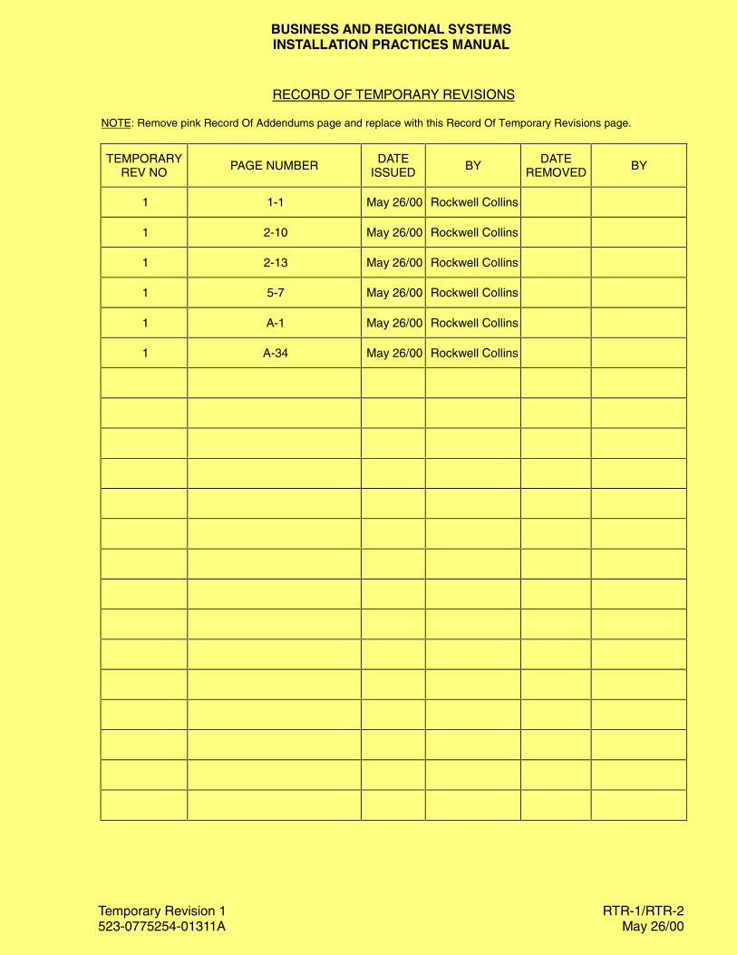
RECORD OF TEMPORARY REVISIONS
NOTE: Remove pink Record Of Addendums page and replace with this Record Of Temporary Revisions page.
TEMPORARYREV NO
PAGE NUMBERDATE
ISSUEDBY
DATEREMOVED
BY
1 1-1 May 26/00 Rockwell Collins
1 2-10 May 26/00 Rockwell Collins
1 2-13 May 26/00 Rockwell Collins
1 5-7 May 26/00 Rockwell Collins
1 A-1 May 26/00 Rockwell Collins
1 A-34 May 26/00 Rockwell Collins

iv
Installation Practices Manual 523-0775254
This page intentionally blank.

1.1 INTRODUCTION .................................................................................................................................................... 1-1
1.2 WIRING INFORMATION ....................................................................................................................................... 1-11.2.1 Wire Type Selection ........................................................................................................................................................1-11.2.2 Measuring Wire Length..................................................................................................................................................1-21.2.3 Wire Marking ..................................................................................................................................................................1-2
1.3 CONNECTOR INFORMATION ............................................................................................................................. 1-21.3.1 Thinline II and Thinline I Connectors...........................................................................................................................1-21.3.2 D-Subminiature Connector ..........................................................................................................................................1-111.3.3 Quick Disconnect Circular Connector..........................................................................................................................1-11
1.4 WIRING CHECKOUT TECHNIQUES................................................................................................................. 1-14
1.5 HARNESS INSTALLATION ................................................................................................................................ 1-14
1.6 SYSTEM CHECKOUT........................................................................................................................................... 1-15
1.7 FIBER-OPTIC CABLE .......................................................................................................................................... 1-151.7.1 Safety Precautions ........................................................................................................................................................1-151.7.2 Fiber-Optic Termination Information..........................................................................................................................1-151.7.3 Fiber-Optic Cabling ......................................................................................................................................................1-16
1.8 COAX CABLE ........................................................................................................................................................ 1-171.8.1 Coax Cable Precautions................................................................................................................................................1-181.8.2 Coax Cable Length and Type .......................................................................................................................................1-18
1.9 SHELF PRACTICES ............................................................................................................................................. 1-191.9.1 Shelf Location ...............................................................................................................................................................1-191.9.2 Shelf Type......................................................................................................................................................................1-19
1.10 EQUIPMENT LOCATION .................................................................................................................................. 1-19
1.11 LRU ELECTROSTATIC DISCHARGE PROTECTION ................................................................................... 1-20
523-0776006-0031183rd Edition, 4 March 1998
Installation Practices Manual
NOTICE: This section replaces second edition dated 6 March 1992.
Wiring, Harness, and System Checkout
Paragraph Page
Table of Contents

List of Effective Pages *The asterisk indicates pages changed, added, or deleted by the current change.
Page No Issue
* Title ........................................... 4 Mar 98* List of Effective Pages............... 4 Mar 98
*1-1 thru 1-20 ............................... 4 Mar 98
Record of RevisionsRETAIN THIS RECORD IN THE FRONT OF THE MANUAL. ON RECEIPT OFREVISIONS, INSERT REVISED PAGES IN THE MANUAL, AND ENTER DATEINSERTED AND INITIALS.
REVNO
REVISIONDATE
INSERTIONDATE/BY
SB NUMBERINCLUDED
REVNO
REVISIONDATE
INSERTIONDATE/BY
SB NUMBERINCLUDED
1st Ed 22 Mar 90 None
2nd Ed 6 Mar 92 None
3rd Ed 4 Mar 98 None
BUSINESS AND REGIONAL SYSTEMSINSTALLATION PRACTICES MANUAL
Temporary Revision 1523-0775254-01311A May 26/00
Installation Practices Manual
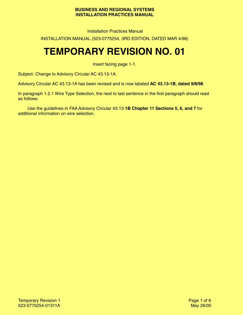
INSTALLATION MANUAL (523-0775254, 3RD EDITION, DATED MAR 4/98)
TEMPORARY REVISION NO. 01Insert facing page 1-1.
Subject: Change to Advisory Circular AC 43.13-1A.
Advisory Circular AC 43.13-1A has been revised and is now labeled AC 43.13-1B, dated 9/8/98.
In paragraph 1.2.1 Wire Type Selection, the next to last sentence in the first paragraph should readas follows:
Use the guidelines in FAA Advisory Circular 43.13-1B Chapter 11 Sections 5, 6, and 7 foradditional information on wire selection.
Page 1 of 6
section Iwiring, harness, and
system checkout
Revised 4 March 1998 1-1
1.1 INTRODUCTION
This manual covers general information to aid in the installation of Collins General Aviation equipment.Most practices described in this manual are not minor aircraft maintenance and must be performed by or in-spected by a properly trained and certified repairman or aircraft mechanic. This section covers wiring, con-nectors, coax cable, harness installation, system checkout, fiber-optics, shelf, and equipment location infor-mation. Other sections in this manual cover topics such as bonding, grounding, antenna installation, dimmercontrols, and mounting information.
1.2 WIRING INFORMATION
This section covers wiring selection, crimping, harness building, and harness installation.
1.2.1 Wire Type Selection
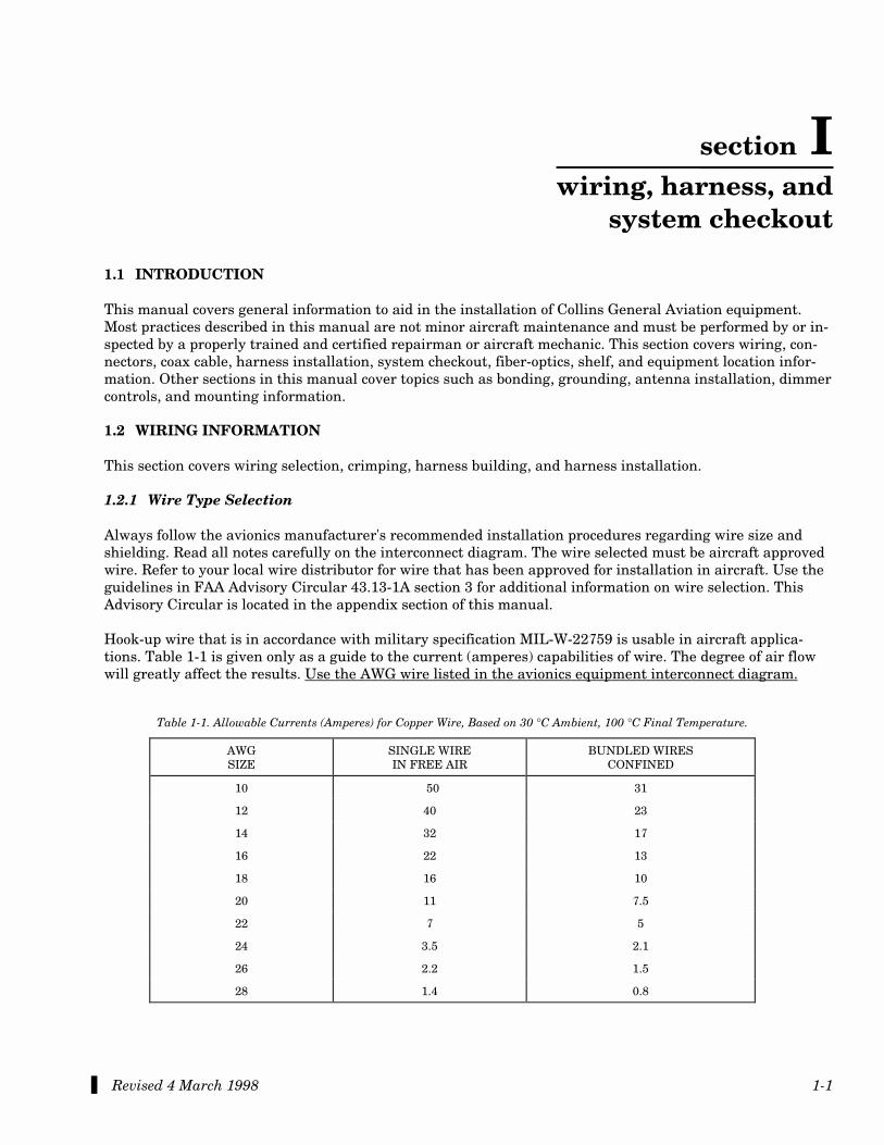
Always follow the avionics manufacturer's recommended installation procedures regarding wire size andshielding. Read all notes carefully on the interconnect diagram. The wire selected must be aircraft approvedwire. Refer to your local wire distributor for wire that has been approved for installation in aircraft. Use theguidelines in FAA Advisory Circular 43.13-1A section 3 for additional information on wire selection. ThisAdvisory Circular is located in the appendix section of this manual.
Hook-up wire that is in accordance with military specification MIL-W-22759 is usable in aircraft applica-tions. Table 1-1 is given only as a guide to the current (amperes) capabilities of wire. The degree of air flowwill greatly affect the results. Use the AWG wire listed in the avionics equipment interconnect diagram.
Table 1-1. Allowable Currents (Amperes) for Copper Wire, Based on 30 °C Ambient, 100 °C Final Temperature.
AWGSIZE
SINGLE WIREIN FREE AIR
BUNDLED WIRESCONFINED
10 50 31
12 40 23
14 32 17
16 22 13
18 16 10
20 11 7.5
22 7 5
24 3.5 2.1
26 2.2 1.5
28 1.4 0.8
Revised 4 March 1998 1-2
wiring, harness, & system checkout 523-0776006
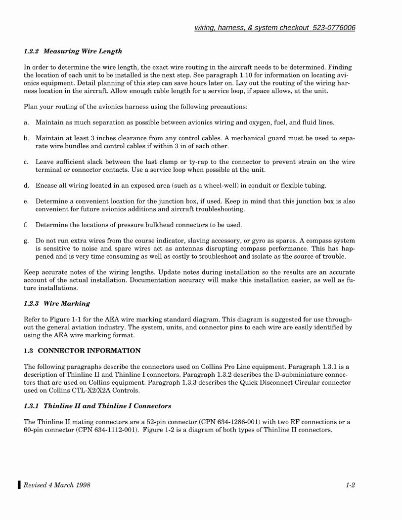
1.2.2 Measuring Wire Length
In order to determine the wire length, the exact wire routing in the aircraft needs to be determined. Findingthe location of each unit to be installed is the next step. See paragraph 1.10 for information on locating avi-onics equipment. Detail planning of this step can save hours later on. Lay out the routing of the wiring har-ness location in the aircraft. Allow enough cable length for a service loop, if space allows, at the unit.
Plan your routing of the avionics harness using the following precautions:
a. Maintain as much separation as possible between avionics wiring and oxygen, fuel, and fluid lines.
b. Maintain at least 3 inches clearance from any control cables. A mechanical guard must be used to sepa-rate wire bundles and control cables if within 3 in of each other.
c. Leave sufficient slack between the last clamp or ty-rap to the connector to prevent strain on the wireterminal or connector contacts. Use a service loop when possible at the unit.
d. Encase all wiring located in an exposed area (such as a wheel-well) in conduit or flexible tubing.
e. Determine a convenient location for the junction box, if used. Keep in mind that this junction box is alsoconvenient for future avionics additions and aircraft troubleshooting.
f. Determine the locations of pressure bulkhead connectors to be used.
g. Do not run extra wires from the course indicator, slaving accessory, or gyro as spares. A compass systemis sensitive to noise and spare wires act as antennas disrupting compass performance. This has hap-pened and is very time consuming as well as costly to troubleshoot and isolate as the source of trouble.
Keep accurate notes of the wiring lengths. Update notes during installation so the results are an accurateaccount of the actual installation. Documentation accuracy will make this installation easier, as well as fu-ture installations.
1.2.3 Wire Marking
Refer to Figure 1-1 for the AEA wire marking standard diagram. This diagram is suggested for use through-out the general aviation industry. The system, units, and connector pins to each wire are easily identified byusing the AEA wire marking format.
1.3 CONNECTOR INFORMATION
The following paragraphs describe the connectors used on Collins Pro Line equipment. Paragraph 1.3.1 is adescription of Thinline II and Thinline I connectors. Paragraph 1.3.2 describes the D-subminiature connec-tors that are used on Collins equipment. Paragraph 1.3.3 describes the Quick Disconnect Circular connectorused on Collins CTL-X2/X2A Controls.
1.3.1 Thinline II and Thinline I Connectors
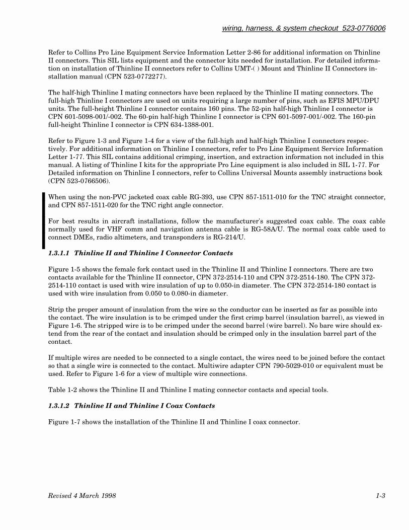
The Thinline II mating connectors are a 52-pin connector (CPN 634-1286-001) with two RF connections or a60-pin connector (CPN 634-1112-001). Figure 1-2 is a diagram of both types of Thinline II connectors.
wiring, harness, & system checkout 523-0776006
Revised 4 March 1998 1-3
Refer to Collins Pro Line Equipment Service Information Letter 2-86 for additional information on ThinlineII connectors. This SIL lists equipment and the connector kits needed for installation. For detailed informa-tion on installation of Thinline II connectors refer to Collins UMT-( ) Mount and Thinline II Connectors in-stallation manual (CPN 523-0772277).
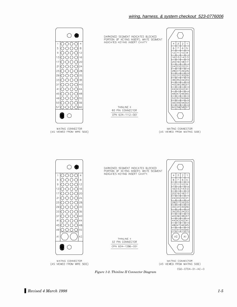
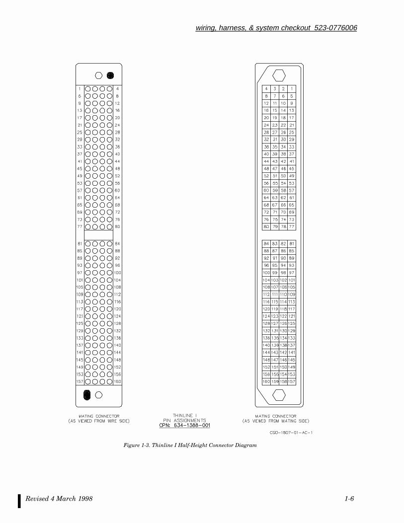
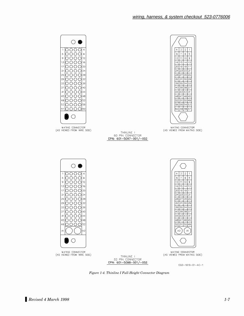
The half-high Thinline I mating connectors have been replaced by the Thinline II mating connectors. Thefull-high Thinline I connectors are used on units requiring a large number of pins, such as EFIS MPU/DPUunits. The full-height Thinline I connector contains 160 pins. The 52-pin half-high Thinline I connector isCPN 601-5098-001/-002. The 60-pin half-high Thinline I connector is CPN 601-5097-001/-002. The 160-pinfull-height Thinline I connector is CPN 634-1388-001.
Refer to Figure 1-3 and Figure 1-4 for a view of the full-high and half-high Thinline I connectors respec-tively. For additional information on Thinline I connectors, refer to Pro Line Equipment Service InformationLetter 1-77. This SIL contains additional crimping, insertion, and extraction information not included in thismanual. A listing of Thinline I kits for the appropriate Pro Line equipment is also included in SIL 1-77. ForDetailed information on Thinline I connectors, refer to Collins Universal Mounts assembly instructions book(CPN 523-0766506).
When using the non-PVC jacketed coax cable RG-393, use CPN 857-1511-010 for the TNC straight connector,and CPN 857-1511-020 for the TNC right angle connector.
For best results in aircraft installations, follow the manufacturer's suggested coax cable. The coax cablenormally used for VHF comm and navigation antenna cable is RG-58A/U. The normal coax cable used toconnect DMEs, radio altimeters, and transponders is RG-214/U.
1.3.1.1 Thinline II and Thinline I Connector Contacts
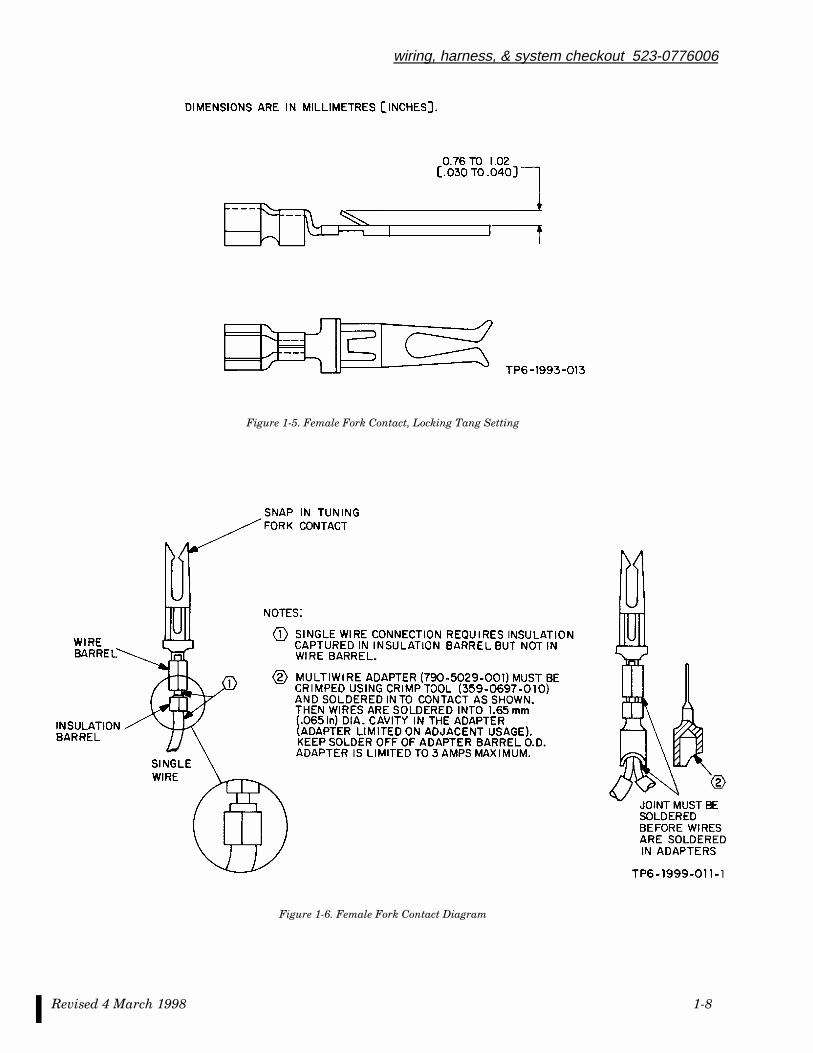
Figure 1-5 shows the female fork contact used in the Thinline II and Thinline I connectors. There are twocontacts available for the Thinline II connector, CPN 372-2514-110 and CPN 372-2514-180. The CPN 372-2514-110 contact is used with wire insulation of up to 0.050-in diameter. The CPN 372-2514-180 contact isused with wire insulation from 0.050 to 0.080-in diameter.
Strip the proper amount of insulation from the wire so the conductor can be inserted as far as possible intothe contact. The wire insulation is to be crimped under the first crimp barrel (insulation barrel), as viewed inFigure 1-6. The stripped wire is to be crimped under the second barrel (wire barrel). No bare wire should ex-tend from the rear of the contact and insulation should be crimped only in the insulation barrel part of thecontact.
If multiple wires are needed to be connected to a single contact, the wires need to be joined before the contactso that a single wire is connected to the contact. Multiwire adapter CPN 790-5029-010 or equivalent must beused. Refer to Figure 1-6 for a view of multiple wire connections.
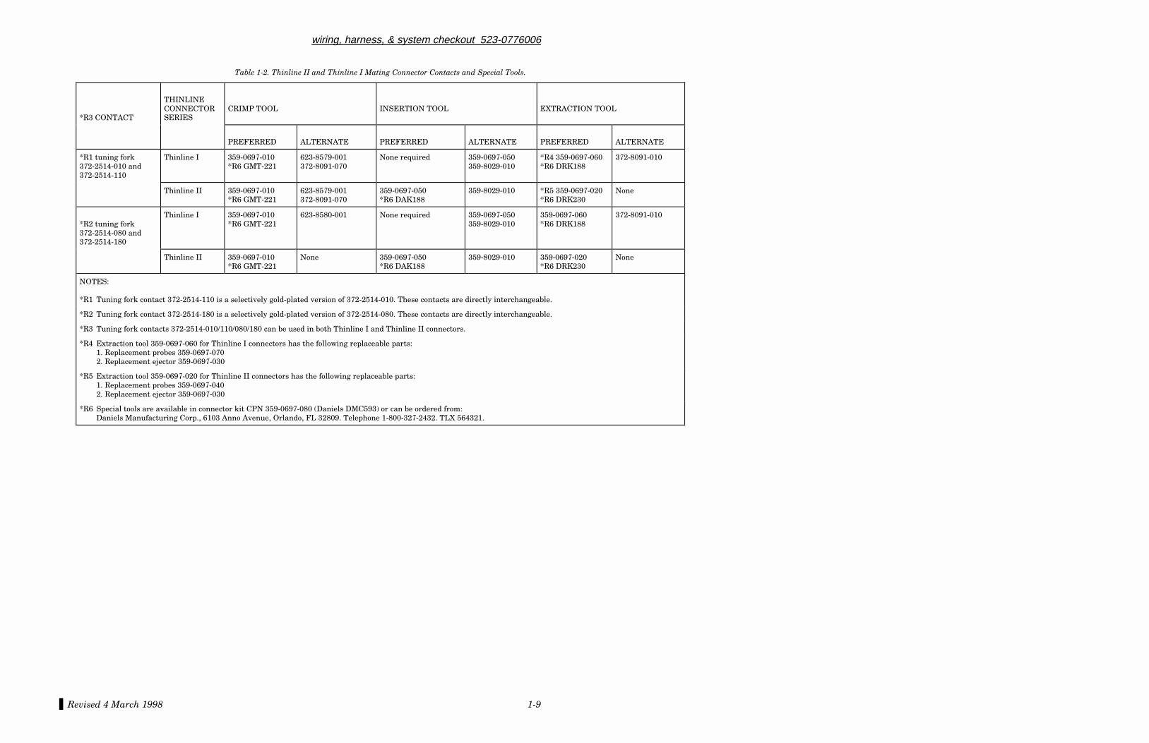
Table 1-2 shows the Thinline II and Thinline I mating connector contacts and special tools.
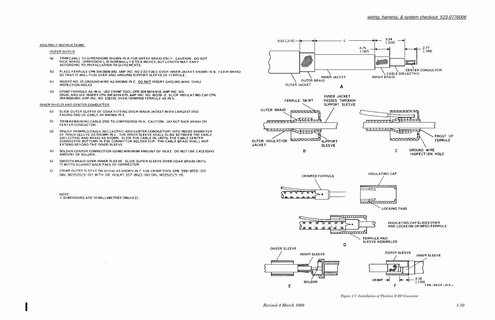
1.3.1.2 Thinline II and Thinline I Coax Contacts
Figure 1-7 shows the installation of the Thinline II and Thinline I coax connector.

wiring, harness, & system checkout 523-0776006
Revised 4 March 1998 1-4
Figure 1-1. AEA Wire Marking Standard
Revised 4 March 1998 1-5
wiring, harness, & system checkout 523-0776006
Figure 1-2. Thinline II Connector Diagram
wiring, harness, & system checkout 523-0776006
Revised 4 March 1998 1-6
Figure 1-3. Thinline I Half-Height Connector Diagram
Revised 4 March 1998 1-7
wiring, harness, & system checkout 523-0776006
Figure 1-4. Thinline I Full-Height Connector Diagram
wiring, harness, & system checkout 523-0776006
Revised 4 March 1998 1-8
Figure 1-5. Female Fork Contact, Locking Tang Setting
Figure 1-6. Female Fork Contact Diagram
Revised 4 March 1998 1-9
wiring, harness, & system checkout 523-0776006
Table 1-2. Thinline II and Thinline I Mating Connector Contacts and Special Tools.
*R3 CONTACT
THINLINECONNECTORSERIES
CRIMP TOOL INSERTION TOOL EXTRACTION TOOL
PREFERRED ALTERNATE PREFERRED ALTERNATE PREFERRED ALTERNATE
*R1 tuning fork372-2514-010 and372-2514-110
Thinline I 359-0697-010*R6 GMT-221
623-8579-001372-8091-070
None required 359-0697-050359-8029-010
*R4 359-0697-060*R6 DRK188
372-8091-010
Thinline II 359-0697-010*R6 GMT-221
623-8579-001372-8091-070
359-0697-050*R6 DAK188
359-8029-010 *R5 359-0697-020*R6 DRK230
None
*R2 tuning fork372-2514-080 and372-2514-180
Thinline I 359-0697-010*R6 GMT-221
623-8580-001 None required 359-0697-050359-8029-010
359-0697-060*R6 DRK188
372-8091-010
Thinline II 359-0697-010*R6 GMT-221
None 359-0697-050*R6 DAK188
359-8029-010 359-0697-020*R6 DRK230
None
NOTES:
*R1 Tuning fork contact 372-2514-110 is a selectively gold-plated version of 372-2514-010. These contacts are directly interchangeable.
*R2 Tuning fork contact 372-2514-180 is a selectively gold-plated version of 372-2514-080. These contacts are directly interchangeable.
*R3 Tuning fork contacts 372-2514-010/110/080/180 can be used in both Thinline I and Thinline II connectors.
*R4 Extraction tool 359-0697-060 for Thinline I connectors has the following replaceable parts:1. Replacement probes 359-0697-0702. Replacement ejector 359-0697-030
*R5 Extraction tool 359-0697-020 for Thinline II connectors has the following replaceable parts:1. Replacement probes 359-0697-0402. Replacement ejector 359-0697-030
*R6 Special tools are available in connector kit CPN 359-0697-080 (Daniels DMC593) or can be ordered from:Daniels Manufacturing Corp., 6103 Anno Avenue, Orlando, FL 32809. Telephone 1-800-327-2432. TLX 564321.
wiring, harness, & system checkout 523-0776006
Revised 4 March 1998 1-10
Figure 1-7. Installation of Thinline II RF Connector
wiring, harness, & system checkout 523-0776006
Revised 4 March 1998 1-11
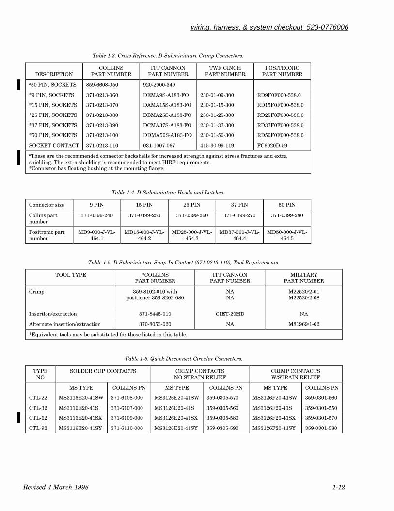
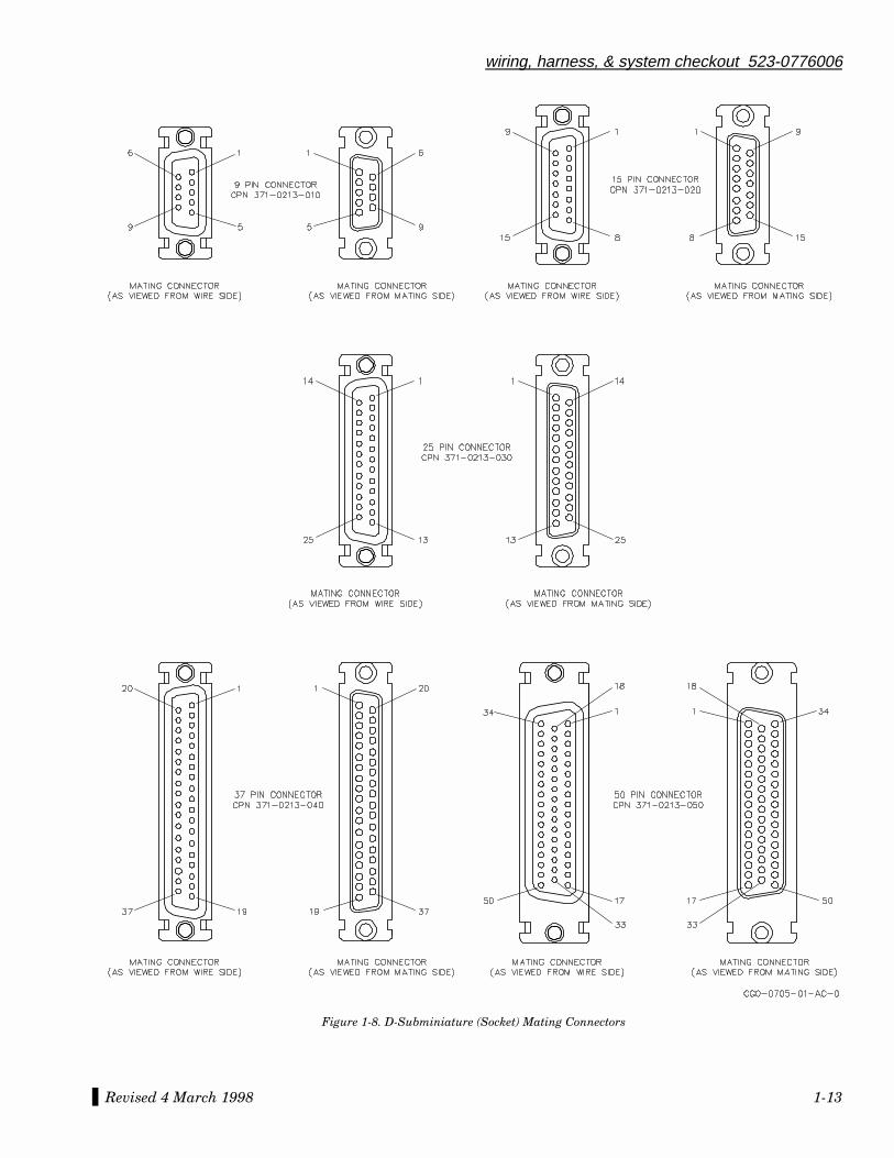
1.3.2 D-Subminiature Connector
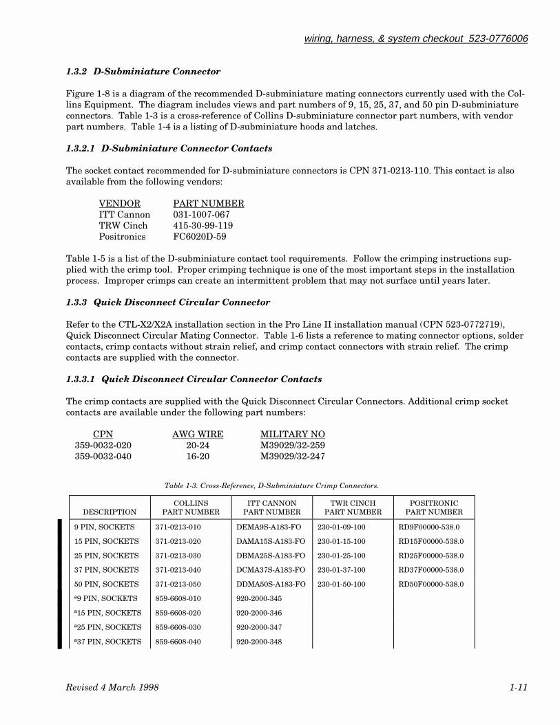
Figure 1-8 is a diagram of the recommended D-subminiature mating connectors currently used with the Col-lins Equipment. The diagram includes views and part numbers of 9, 15, 25, 37, and 50 pin D-subminiatureconnectors. Table 1-3 is a cross-reference of Collins D-subminiature connector part numbers, with vendorpart numbers. Table 1-4 is a listing of D-subminiature hoods and latches.
1.3.2.1 D-Subminiature Connector Contacts
The socket contact recommended for D-subminiature connectors is CPN 371-0213-110. This contact is alsoavailable from the following vendors:
VENDOR PART NUMBERITT Cannon 031-1007-067TRW Cinch 415-30-99-119Positronics FC6020D-59
Table 1-5 is a list of the D-subminiature contact tool requirements. Follow the crimping instructions sup-plied with the crimp tool. Proper crimping technique is one of the most important steps in the installationprocess. Improper crimps can create an intermittent problem that may not surface until years later.
1.3.3 Quick Disconnect Circular Connector
Refer to the CTL-X2/X2A installation section in the Pro Line II installation manual (CPN 523-0772719),Quick Disconnect Circular Mating Connector. Table 1-6 lists a reference to mating connector options, soldercontacts, crimp contacts without strain relief, and crimp contact connectors with strain relief. The crimpcontacts are supplied with the connector.
1.3.3.1 Quick Disconnect Circular Connector Contacts
The crimp contacts are supplied with the Quick Disconnect Circular Connectors. Additional crimp socketcontacts are available under the following part numbers:
CPN AWG WIRE MILITARY NO359-0032-020 20-24 M39029/32-259359-0032-040 16-20 M39029/32-247
Table 1-3. Cross-Reference, D-Subminiature Crimp Connectors.
DESCRIPTIONCOLLINS
PART NUMBERITT CANNON
PART NUMBERTWR CINCH
PART NUMBERPOSITRONIC
PART NUMBER
9 PIN, SOCKETS 371-0213-010 DEMA9S-A183-FO 230-01-09-100 RD9F00000-538.0
15 PIN, SOCKETS 371-0213-020 DAMA15S-A183-FO 230-01-15-100 RD15F00000-538.0
25 PIN, SOCKETS 371-0213-030 DBMA25S-A183-FO 230-01-25-100 RD25F00000-538.0
37 PIN, SOCKETS 371-0213-040 DCMA37S-A183-FO 230-01-37-100 RD37F00000-538.0
50 PIN, SOCKETS 371-0213-050 DDMA50S-A183-FO 230-01-50-100 RD50F00000-538.0
ª9 PIN, SOCKETS 859-6608-010 920-2000-345
ª15 PIN, SOCKETS 859-6608-020 920-2000-346
ª25 PIN, SOCKETS 859-6608-030 920-2000-347
ª37 PIN, SOCKETS 859-6608-040 920-2000-348
wiring, harness, & system checkout 523-0776006
Revised 4 March 1998 1-12
Table 1-3. Cross-Reference, D-Subminiature Crimp Connectors.
DESCRIPTIONCOLLINS
PART NUMBERITT CANNON
PART NUMBERTWR CINCH
PART NUMBERPOSITRONIC
PART NUMBER
ª50 PIN, SOCKETS 859-6608-050 920-2000-349
*9 PIN, SOCKETS 371-0213-060 DEMA9S-A183-FO 230-01-09-300 RD9F0F000-538.0
*15 PIN, SOCKETS 371-0213-070 DAMA15S-A183-FO 230-01-15-300 RD15F0F000-538.0
*25 PIN, SOCKETS 371-0213-080 DBMA25S-A183-FO 230-01-25-300 RD25F0F000-538.0
*37 PIN, SOCKETS 371-0213-090 DCMA37S-A183-FO 230-01-37-300 RD37F0F000-538.0
*50 PIN, SOCKETS 371-0213-100 DDMA50S-A183-FO 230-01-50-300 RD50F0F000-538.0
SOCKET CONTACT 371-0213-110 031-1007-067 415-30-99-119 FC6020D-59
ªThese are the recommended connector backshells for increased strength against stress fractures and extrashielding. The extra shielding is recommended to meet HIRF requirements.*Connector has floating bushing at the mounting flange.
Table 1-4. D-Subminiature Hoods and Latches.
Connector size 9 PIN 15 PIN 25 PIN 37 PIN 50 PIN
Collins partnumber
371-0399-240 371-0399-250 371-0399-260 371-0399-270 371-0399-280
Positronic partnumber
MD9-000-J-VL-464.1
MD15-000-J-VL-464.2
MD25-000-J-VL-464.3
MD37-000-J-VL-464.4
MD50-000-J-VL-464.5
Table 1-5. D-Subminiature Snap-In Contact (371-0213-110), Tool Requirements.
TOOL TYPE *COLLINSPART NUMBER
ITT CANNONPART NUMBER
MILITARYPART NUMBER
Crimp 359-8102-010 withpositioner 359-8202-080
NANA
M22520/2-01M22520/2-08
Insertion/extraction 371-8445-010 CIET-20HD NA
Alternate insertion/extraction 370-8053-020 NA M81969/1-02
*Equivalent tools may be substituted for those listed in this table.
Table 1-6. Quick Disconnect Circular Connectors.
TYPENO
SOLDER CUP CONTACTS CRIMP CONTACTSNO STRAIN RELIEF
CRIMP CONTACTSW/STRAIN RELIEF
MS TYPE COLLINS PN MS TYPE COLLINS PN MS TYPE COLLINS PN
CTL-22 MS3116E20-41SW 371-6108-000 MS3126E20-41SW 359-0305-570 MS3126F20-41SW 359-0301-560
CTL-32 MS3116E20-41S 371-6107-000 MS3126E20-41S 359-0305-560 MS3126F20-41S 359-0301-550
CTL-62 MS3116E20-41SX 371-6109-000 MS3126E20-41SX 359-0305-580 MS3126F20-41SX 359-0301-570
CTL-92 MS3116E20-41SY 371-6110-000 MS3126E20-41SY 359-0305-590 MS3126F20-41SY 359-0301-580
Revised 4 March 1998 1-13
wiring, harness, & system checkout 523-0776006
Figure 1-8. D-Subminiature (Socket) Mating Connectors
Revised 4 March 1998 1-14
wiring, harness, & system checkout 523-0776006
1.4 WIRING CHECKOUT TECHNIQUES
This section contains information regarding suggested methods for checkout of an aircraft wiring harness.These suggested methods apply at any time the wiring of an aircraft avionics system is being investigated,either at the time of installation or when troubleshooting an avionics system problem.
The most difficult type of squawks to repair are those that are intermittent. One of the main causes for in-termittent squawks is found to be either "a bad pin," "bad pin tension," "a spread pin," or any one of manydescriptions of the same type of failure. In most cases, this type of failure is the result of improper wiringcheckout techniques.
The use of paper clips, upholstery pins, safety wire, test probes, etc while performing continuity checks willcause problems in the future even if they save a few minutes time during the actual wiring checkout. If theobject you are using to assist in the wiring checkout is not the pin or socket that has been designed and ma-chined to fit the contact in question, it is possible that you may cause damage to the contact.
It is recommended that any aircraft avionics system troubleshooting that requires wiring checkout be ac-complished through the use of a breakout box. Properly designed breakout boxes have the correct contactsinstalled in the mating connectors so as to ensure no damage is done to the rack or aircraft mating connectorduring the checkout period.
Collins has made available a number of breakout boxes during the introduction of our flight control products.The current CTS-9 is used with a variety of products such as the EFIS-85/86 family and the APS-85 autopilotsystem. The CTS-10 is used with the EHSI-74, AHRS Air Data, APS-65, and other Pro Line II products withup to three Thinline connectors using 60 pins with no rf connectors. These breakout boxes are designed toallow the aircraft wiring to be checked out with or without the unit connected and allow monitoring of in-coming and outgoing signals. Others are designed to allow the user to open one or more connections at a timefor circuit isolation or signal rejection. With the introduction of more advanced digital avionics systems, thistype of flexibility is necessary.
The available Collins breakout boxes are listed below:
BREAKOUT COLLINS BOX PART NUMBER DESCRIPTION
CTS-9 622-6720-001 Breakout box for 160-pin Thinline connectors.CTS-10 622-4561-001 Breakout box for 60-pin Thinline connectors.
Additional information is available in the CTS-9/10 Universal ATR Breakout Boxes instruction book, CPN523-0770653.
1.5 HARNESS INSTALLATION
The following paragraphs contain guides for the installation of an aircraft avionics harness. Route and sup-port avionics wiring to prevent relative movement within the aircraft and provide protection against chafing.Soft insulation tubing is not regarded as satisfactory mechanical protection against abrasion or considered asubstitute for proper clamping or tying. Secure all wiring so it is electrically and mechanically sound.
It is not advisable to route wire below a battery or closer than six inches from the bilge of the fuselage due tothe possible damage from acid and fluids. Encase all wiring located in the wheel well areas in conduit orflexible tubing. Maintain a minimum clearance of three inches from any control cable or install a mechanicalguard. Maintain as much separation as possible between avionics wiring and oxygen lines, fuel, and fluidlines. Always ensure that the wiring is routed above these types of lines, never below. Support all wire bun-
Revised 4 March 1998 1-15
wiring, harness, & system checkout 523-0776006
dles from the fuselage with MS type clamps, cable straps or ty-raps and exercise caution to ensure wires arenot touching structural members; always use grommets, feedthrough insulators, or appropriate clamps.
Leave sufficient slack between the last clamp or ty-rap to prevent strain on the wire terminal or connectorand to permit replacement of terminals or removal of equipment for maintenance purposes. Leave a serviceloop when possible at the unit.
1.6 SYSTEM CHECKOUT
Upon completion of the harness and equipment installation, a complete checkout of the avionics system isrequired. Follow each equipment postinstallation check procedure found in the installation manuals. Aftercompletion of the postinstallation checks, a flight is recommended. Environmental (vibration, temperature),problems may not be found in the ground checkout. A flight test checks the installation in actual operatingconditions.
1.7 FIBER-OPTIC CABLE
The following paragraphs explain some of the fiber-optics installation requirements.
1.7.1 Safety Precautions
Handle bare fiber with care. The core end of the fiber is glass that can pierce the skin and break off. This is ahazard only when terminating a fiber end with a connector or a splice.
Use caution when viewing fiber ends or optical ports under magnification.
Potential eye problems result from invisible wavelengths, collimated and light intensity of unknown sources.It is always safer and more accurate to use a meter to measure light output.
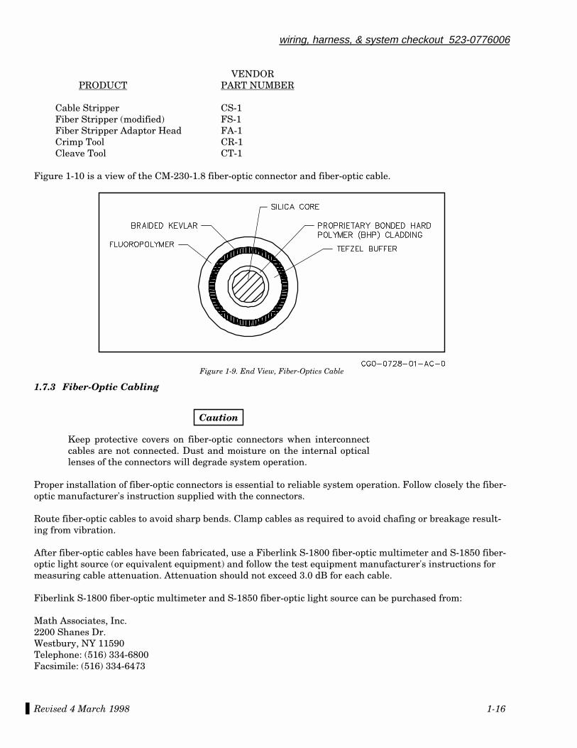
1.7.2 Fiber-Optic Termination Information
Fiber optics require special tools to connect, splice, and terminate fiber-optic cable. There are essentially twotypes of cable used in aircraft today. A hard-clad silica optical cable (crimp) and Flight Light™ aerospace ca-ble (epoxy) are available for use in aircraft installations. Figure 1-9 is an end view of the hard-clad silica op-tical cable. Each type of cable requires different connectors. The hard-clad silica optical cable is recom-mended for use in the Collins HF-9000 System. The following is a list of the recommended fiber-optictermination kit and cable for use with the HF-9000 System.
PRODUCT CPN VENDOR PN
Termination Kit 247-0029-001 K-5Cable (crimp) 216-0029-010 HCP-M0200T-D01FS-10Connector 261-0054-010 CC230-1.8
Fiber-Optic vendor:
Ensign-Bickford Optics Company16-18 Ensign Drive, P.O. Box 1260Avon, Connecticut 06001Telephone: (203) 678-0371Telex: 510 600 2911
The TK-5 Fiber Optic Termination Kit contains the following:
Revised 4 March 1998 1-16
wiring, harness, & system checkout 523-0776006
VENDOR PRODUCT PART NUMBER
Cable Stripper CS-1Fiber Stripper (modified) FS-1Fiber Stripper Adaptor Head FA-1Crimp Tool CR-1Cleave Tool CT-1
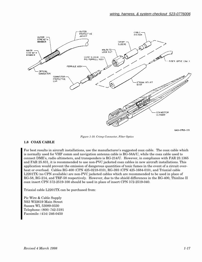
Figure 1-10 is a view of the CM-230-1.8 fiber-optic connector and fiber-optic cable.
Figure 1-9. End View, Fiber-Optics Cable
1.7.3 Fiber-Optic Cabling
Caution
Keep protective covers on fiber-optic connectors when interconnectcables are not connected. Dust and moisture on the internal opticallenses of the connectors will degrade system operation.
Proper installation of fiber-optic connectors is essential to reliable system operation. Follow closely the fiber-optic manufacturer's instruction supplied with the connectors.
Route fiber-optic cables to avoid sharp bends. Clamp cables as required to avoid chafing or breakage result-ing from vibration.
After fiber-optic cables have been fabricated, use a Fiberlink S-1800 fiber-optic multimeter and S-1850 fiber-optic light source (or equivalent equipment) and follow the test equipment manufacturer's instructions formeasuring cable attenuation. Attenuation should not exceed 3.0 dB for each cable.
Fiberlink S-1800 fiber-optic multimeter and S-1850 fiber-optic light source can be purchased from:
Math Associates, Inc.2200 Shanes Dr.Westbury, NY 11590Telephone: (516) 334-6800Facsimile: (516) 334-6473
Revised 4 March 1998 1-17
wiring, harness, & system checkout 523-0776006
Figure 1-10. Crimp Connector, Fiber Optics
1.8 COAX CABLE
For best results in aircraft installations, use the manufacturer's suggested coax cable. The coax cable whichis normally used for VHF comm and navigation antenna cable is RG-58A/U, while the coax cable used toconnect DME's, radio altimeters, and transponders is RG-214/U. However, in compliance with FAR 23.1365and FAR 25.831, it is recommended to use non-PVC jacketed coax cables in new aircraft installations. Thisapplication would prevent the emission of dangerous quantities of toxic fumes in the event of a circuit over-heat or overload. Cables RG-400 (CPN 425-0218-010), RG-393 (CPN 425-1684-010), and Triaxial cableL2201TX (no CPN available) are non-PVC jacketed cables which are recommended to be used in place ofRG-58, RG-214, and TRF-58 respectively. However, due to the shield differences in the RG-400, Thinline IIcoax insert CPN 372-2519-100 should be used in place of insert CPN 372-2519-040.
Triaxial cable L2201TX can be purchased from:
Pic Wire & Cable SupplyN63 W22619 Main StreetSussex WI, 53089-0330Telephone: (800) 742-3191Facsimile: (414) 246-0450
Revised 4 March 1998 1-18
wiring, harness, & system checkout 523-0776006
1.8.1 Coax Cable Precautions
The following information contains precautions for selection of coax cable.
There are some underlying problems when specifying coax cable for use in severe environments. In tempera-ture environments of -55 °C to +71 °C, coax cable with a polyethylene dielectric may back the pinout of thereceptacle inside the coaxial connectors. The polyethylene and center conductor shrink more than the shieldand outer insulation. This sometimes results in a poor to nonexistent connection at the coax cable/connectorjunction. In many installations, a small arcing will occur at the contact point when this problem occurs. Thisarcing results in destruction of the junction or a significant increase in the connector insertion loss when op-erating at cold temperatures. High altitude operation contributes to this problem due to the decrease of thegap required for arcing.
The coax cable recommended is one that has Teflon dielectric. Contact the coax cable manufacturer if thecurrent coax dielectric material is unknown.
A problem with the coaxial cable may occur if the cable is bent or crimped too severely. The problem occurswith a constant stress on the internal conductor which tries to pull it towards the shield. After a while thecenter conductor will migrate over to the shield. This problem is not easily found using an ohmmeter becausea direct short only occurs when the center conductor contacts the shield directly. In the case of a transmittercoax, the arcing mentioned earlier may result in a high loss at the RF frequency and no detectable dc resis-tance at any time. The time for development of this problem is reduced with temperature cycling. The prob-lem is more severe when using Teflon dielectric.
The coax installation should be designed to eliminate any tight bends of over-tightened cable clamps. Re-member, some materials shrink at cold temperatures.
1.8.2 Coax Cable Length and Type
Coax cable length is primarily determined by the distance between the antenna and unit. Another factor isthe routing necessary to reduced interference. The equipment's installation manual lists the type coax toconnect the unit to the appropriate antenna.
Two additional important factors on determining coax cable length are the velocity factor and signal loss indB/foot. Both of these factors are directly related to the maximum length of the coax cable. Each cable typehas different loss and velocity factor characteristics at different frequencies.
Velocity factor in some cases is used to determine the cable length required, (example the ALT-50A/55B).Some units need to know the time delay (velocity factor) of the cable used. These units use the time delay incalculations when the time between transmitting and receiving a signal is needed (example, the ALT-50A/55B measures the distance above ground by determining the time it takes for a signal to leave thetransmitter until it returns after bouncing off the ground).
Signal loss is measured by the manufacture of the cable at different frequencies. The equipment type mayprovide you with a maximum allowable loss for that unit. Example, coax cable loss for the DME-42/442should not exceed 3 dB. The formula is:
Maximum Loss ÷ Nominal Loss = Maximum Length of cable
Revised 4 March 1998 1-19
wiring, harness, & system checkout 523-0776006
Example:
RG-142B/U has a loss factor of 0.13 dB/ft at the nearest frequency used by the DME. This meansif you used RG-142B/U coax cable, the maximum cable length would be approximately 23 feet.
Maximum Loss (3 dB) ÷ Nominal Loss (.013 dB/ft) = Maximum Length (23.077 ft)
Consult your coax supplier for additional information of velocity and signal loss factors.
1.9 SHELF PRACTICES
Avionics shelves are normally predetermined by the aircraft manufacturer. Guidelines for locating equip-ment on the shelf are provided in the following paragraphs. The type of equipment to be installed on theshelf determines the size and strength of the shelf to be used. Bonding of shelves should be checked per thebonding section in this manual.
1.9.1 Shelf Location
The main avionics shelf locations are determined by the aircraft manufacturer. Maintenance accessibilityshould be a main consideration in shelf location. In today's aircraft, space for avionics has become increas-ingly difficult to find. Avionics equipment should be easy to find and remove. The additional costs of difficult-to-reach avionics reflect poorly on the installing agency. If possible, changes in the aircraft to improve acces-sibility to avionics may be warranted. Always consult a certified aircraft mechanic if changes require modifi-cation to the aircraft structure. Think of possible alternatives if the location of the shelf is difficult to access.Consult aircraft mechanics or the aircraft manufacturer for additional information on access.
1.9.2 Shelf Type
Accelerometers and gyros must be mounted on a solid shelf. Flimsy shelves have been responsible for manyaircraft problems which are difficult to recognize as an installation deficiency. If there is any doubt about theshelf to be used, it should be strengthened as a precautionary measure. Honeycomb shelves provide a light-weight alternative to increase shelf strength. Bonding of honeycomb shelves is covered in the bonding sec-tion of the manual. It should be noted that honeycomb shelf bonding is a specialized procedure.
1.10 EQUIPMENT LOCATION
The following paragraphs provide guidelines for equipment location. Equipment location should be the firststep in the installation process.
Each installation presents unique problems in equipment location. Custom installations provide a challengeto the installer to find the best location for avionics equipment. Each piece of avionics requires considerationas to environment, proximity to antennas, proximity to associated equipment, and accessibility. The follow-ing steps are to be used as a guide.
a. List all the equipment to be installed.
b. Map out available shelf area.
c. Determine which systems/units require system separation in accordance with the FARs. Plan wire runsand equipment location accordingly.
d. Map out the location of antennas.
Revised 4 March 1998 1-20
wiring, harness, & system checkout 523-0776006
e. Start locating equipment that is required to be within a certain distance of its associated antenna. (Ex-ample: Radio Altimeter)
f. Locate equipment requiring a special shelf, such as a gyro.
g. Keep in mind the bulkhead wires required for interconnecting equipment.
h. Locate the rest of the equipment on shelves.
i. It may be useful to build "mockup" boxes out of cardboard to be sure equipment can fit in the locationsselected.
Some of the cautions to observe:
a. Do not mount units piggyback style if they contain an accelerometer. The 562C-8( ) Yaw Damper Com-puter contains an accelerometer. Installations in which this unit was piggyback exhibited problems ofrudder kick and erratic rudder.
b. Rate and vertical gyros should be mounted as close to the aircraft center of gravity (CG) as possible.
c. Flux detectors should be mounted in an area free of any magnetic forces (electrical or magnetic objects).Ensure there are no screws, nuts, or other material in the area that can become magnetized. If the fluxdetector is to be mounted in the aft fuselage, install far enough away from any baggage area so that itcannot be influenced by any material that a passenger may be carrying.
1.11 LRU ELECTROSTATIC DISCHARGE PROTECTION
Caution should be exercised when removing LRU (line replaceable units) for repair. Some units have par-tially exposed parts that are sensitive to electrostatic discharge. Some LRUs have modules that can be re-moved for repair. These modules have exposed parts and connectors that are also sensitive to ESD. Normallythese units/modules are marked with an ESD warning label. Maintenance technicians should be grounded tothe aircraft when replacing ESD sensitive LRUs or modules. When removed, the ESD sensitive unit/modulemust be placed in a conductive bag. This will protect the unit/module from electrical damage to electrostaticsensitive devices.
2.1 INTRODUCTION .................................................................................................................................................... 2-12.1.1 RF Strap for Reducing RF Interference.........................................................................................................................2-1
2.2 GROUNDING AND BONDING REQUIREMENTS (ELECTROMAGNETIC PROTECTIONPRACTICES) .......................................................................................................................................................... 2-1
2.2.1 General ............................................................................................................................................................................2-12.2.2 Specific Requirements ....................................................................................................................................................2-22.2.3 Equipment Grounding and Bonding (Refer to Figure 2-1) ...........................................................................................2-22.2.4 Marginal Practices and Associated Problems ...............................................................................................................2-42.2.5 Cable Shielding (Refer to Figures 2-2 and 2-3) .............................................................................................................2-42.2.6 Cable and Connector Selection.......................................................................................................................................2-82.2.7 Cable Routing..................................................................................................................................................................2-92.2.8 Maintenance Considerations........................................................................................................................................2-102.2.9 References .....................................................................................................................................................................2-102.2.10 Shield Treatment of Microphone Jacks .....................................................................................................................2-102.2.11 Definitions of Types of Interference...........................................................................................................................2-11
2.3 CONTROL SURFACE BONDING........................................................................................................................ 2-122.3.1 Bonding Aluminum Surfaces .......................................................................................................................................2-122.3.2 Bond Testing .................................................................................................................................................................2-122.3.3 Honeycomb Shelf Bonding............................................................................................................................................2-13
523-0776007-0031183rd Edition, 4 March 1998
Installation Practices Manual
NOTICE: This section replaces second edition dated 6 March 1992.
Bonding and Grounding Practices
Paragraph Page
Table of Contents

List of Effective Pages *The asterisk indicates pages changed, added, or deleted by the current change.
Page No Issue
* Title ........................................... 4 Mar 98* List of Effective Pages............... 4 Mar 98* 2-1 thru 2-16.............................. 4 Mar 98
Record of RevisionsRETAIN THIS RECORD IN THE FRONT OF THE MANUAL. ON RECEIPT OFREVISIONS, INSERT REVISED PAGES IN THE MANUAL, AND ENTER DATEINSERTED AND INITIALS.
REVNO
REVISIONDATE
INSERTIONDATE/BY
SB NUMBERINCLUDED
REVNO
REVISIONDATE
INSERTIONDATE/BY
SB NUMBERINCLUDED
1st Ed 22 Mar 90 None
2nd Ed 6 Mar 92 None
3rd Ed 4 Mar 98 None
section IIbonding and grounding practices
Revised 4 March 1998 2-1
2.1 INTRODUCTION
The following paragraphs describe bonding requirements as related to the installation of avionics equipment.It includes methods for achieving acceptable metal-to-metal electrical bonding in equipment racks and otheraircraft structures to insure a low impedance bond from equipment chassis to airframe. Also discussed arewiring practices related to termination of shields and connecting equipment ground wires and power re-turns. Proper attention to these installation methods and requirements will help to assure acceptable HIRF,lightning, and EMI performance of the installed equipment.
2.1.1 RF Strap for Reducing RF Interference
RF bonding or grounding requires a strap of metal instead of a wire. This strap must be bonded directly tothe airframe using silver- or tin-plated copper strap or aluminum strap or equivalent structure. The lengthto width ratio of the strap should not be more than 5 to 1 (that is, 127-mm (5-in) strap should be minimum of25.4 mm (1 in) wide).
Bonding to anodized or painted surfaces is not acceptable for good RF grounds. Surfaces to be bonded shouldbe sanded free of paint or anodic film and joined using screws with washers to ensure maximum surface con-tact over as large an area as possible. Materials should be carefully selected to avoid corrosion due to dis-similar metals. An electrically conductive substance should be used on all bare metal surfaces to retard cor-rosion.
2.2 GROUNDING AND BONDING REQUIREMENTS (ELECTROMAGNETIC PROTECTIONPRACTICES)
The FAA has issued policy guidelines concerning the operation of flight-critical and essential systems whenexposed to the possible hazards of High Intensity Radiated electromagnetic Fields (HIRF) and the indirecthazards of lightning. Also of concern are the increasing number of incidents of interference to aircraft radionavigation and communication operations, resulting from EMI produced by avionics equipment and wiring.Proper shielding and grounding techniques have proven to be extremely important in protecting equipmentagainst these electromagnetic hazards. The practices given in the following paragraphs are designed tominimize HIRF, EMI, and lightning hazards.
2.2.1 General
The objective of any avionics installation is to provide an operational system that properly performs all func-tions at all times. To achieve this goal requires that consideration be given to methods of interconnection andgrounding that will provide the proper distribution of signals and power while minimizing the systems sus-ceptibility to interference from internal and external energy sources.
A prerequisite for providing equipment protection is the establishment of a a reference ground plane and themeans of providing adequate connection. Making a connection to the ground plane is grounding, and themechanical method of providing a low impedance union between conductors is electrical bonding. For air-craft installations, the airframe functions as the reference ground plane. The low impedance bonding of the

bonding and grounding practices 523-0776007
Revised 4 March 1998 2-2
various rack, mounts, panels, and equipment chassis provide the needed protection. In the evaluation ofbonding needs, there are two distinct and separate considerations:
a. The equipment bonding must provide a low impedance path to the airframe to ensure that signals gen-erated and exchanged between units are referenced to a common level, and an adequate earth path isprovided to cater for short circuit conditions.
b. Provide a low impedance path suitable for radio frequency protection.
The differences in the magnitude and nature of a. and b. above dictate the type of loading path required ineach case. In paragraph a., the currents are usually DC or low frequency AC, and of a magnitude measuredin amps under fault conditions. Hence, the resistive component of the bond path impedance is the dominantfeature. It should be kept to a minimum and the path should be capable of carrying the maximum currentthat can pass through the unit under fault conditions. In paragraph b., because of the high frequency of thecurrents involved, the inductive component of the path impedance is the critical feature, and it should bekept to a minimum. Consequently, while a cable of adequate current rating and suitably terminated mayprovide an acceptable path for paragraph a., it's inherent inductance could render it unsuitable for radio fre-quency bonding.
2.2.2 Specific Requirements
The following guidelines should be used as a basis for practices used for installation of all Collins avionics.Specific requirements that must be met when installing Collins avionics systems and equipment are:
The installation requirements defined on the interconnect diagrams and other installation data provided byCollins must be followed completely. Any deviations must be evaluated individually.
Workmanship and quality control is very important. Past installation standards and practices may not beadequate for modern protection requirements. Dressing of shields, length of strapping wires, bonding, etc.are critical to provide protection.
Connectors with conductive backshells and good conductivity of exterior mating surfaces to provide 360 de-grees of shielding are now being used where possible. Connectors and hardware called out on installationcontrol drawings for individual equipment or approved equivalent must be used.
2.2.3 Equipment Grounding and Bonding (Refer to Figure 2-1.)
To minimize electromagnetic effects upon the avionics equipment a low impedance/low resistance plane ofreference is required. For convenience this is referred to as a ground plane, even though a connection toearth is not necessarily involved. Such is the case for aircraft installations. The airframe functions as theground plane and therefore becomes the reference plane. The primary objective of a good installation is tominimize the impedance between the primary aircraft structure and the various racks, mounts, and equip-ment chassis.
In designing and establishing equipment bonding and grounding methods, it is necessary to consider the fre-quency spectrum of the electromagnetic effects for which protection is required. By far the most favorablemethod for bonding is to provide direct bonding between structures in such a way as to maximize contactarea and minimize contact resistance between the surfaces being bonded. RF currents seek the most directpath to the reference plane. Forcing them away from this path by bonding in only one location or with insuf-ficient surface area introduces impedance which can seriously degrade system performance, especially athigher frequencies. In general, direct bonds include permanent metal-to-metal joints formed of machinedmetal surfaces or with electrically conductive joints held together by fasteners. Where screws are used to se-cure metallic surfaces, the screws should not be the only conductive path between metallic surfaces. Non-conductive paint should be removed to expose the metallic surface where contact is made. Good bonding im-plies attention to bonds between all structures in the path between the equipment chassis and the primary

Revised 4 March 1998
bonding and grounding practices 523-0776007
2-3
aircraft structure. With proper attention to direct bonding methods, individual bonds between metal struc-tures should be well below 500 micro-ohms. An indication of a good equipment installation is a DC resis-tance of 2.5 milliohms or less between the equipment and the primary aircraft structure. it is important torealize that bonds within the individual structures between the equipment chassis and primary aircraftstructure need to be considerably less than 2.5 milliohms.
Good bonding practices in cabling require all aircraft electrical systems such as generators, ignition systems,power supplies, etc., be bonded and grounded. LRU mounts must be bonded directly to the airframe ground.This provides positive grounding of the mount, to which the shield grounds and chassis ground safety wireare attached.
Figure 2-1. Typical Grounding Connections
bonding and grounding practices 523-0776007
Revised 4 March 1998 2-4
2.2.4 Marginal Practices and Associated Problems
At the LRU indicator, display and/or control which are panel or console mounted, shields are terminated toconnector backshell stud and nut assemblies or a ground stud provided. If the backshell connection cannotmake a known positive low impedance ground through the case of the LRU through panel/ pedestal to air-frame, then a connector backshell RF grounding strap connected to airframe will be necessary. This will helpto achieve a low impedance shield ground. Other methods include:
a. Use of multiple bonding straps.b. Use of multiple ground points for each instrument.c. Use of wider and thicker bonding straps.d. Use of instrument panel for ground point by spot facing attach points of instruments and instrument
panel.e. Locate ground studs on instrument panel and position to accept the backshell bonding straps of a length
to allow disconnect of connectors. Add multiple bonding straps on the instrument panel to airframeground points. Corrosion proof to maintain low surface resistance.
Solid flexible tinned copper with a 5 to 1 length to width ratio is highly preferred for bonding straps as it ex-hibits the lowest impedance when compared to tinned copper braid or tinned stranded copper wire of thesame length. The strap length should be as short as possible as all straps will exhibit some inductive reac-tance that will combine with the stray capacitance to become a parallel resonant, high impedance, circuit atsome frequency. As the strap is shorter, the frequency will be higher. When this occurs the strap no longerprovides a good bonding path.
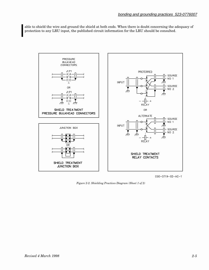
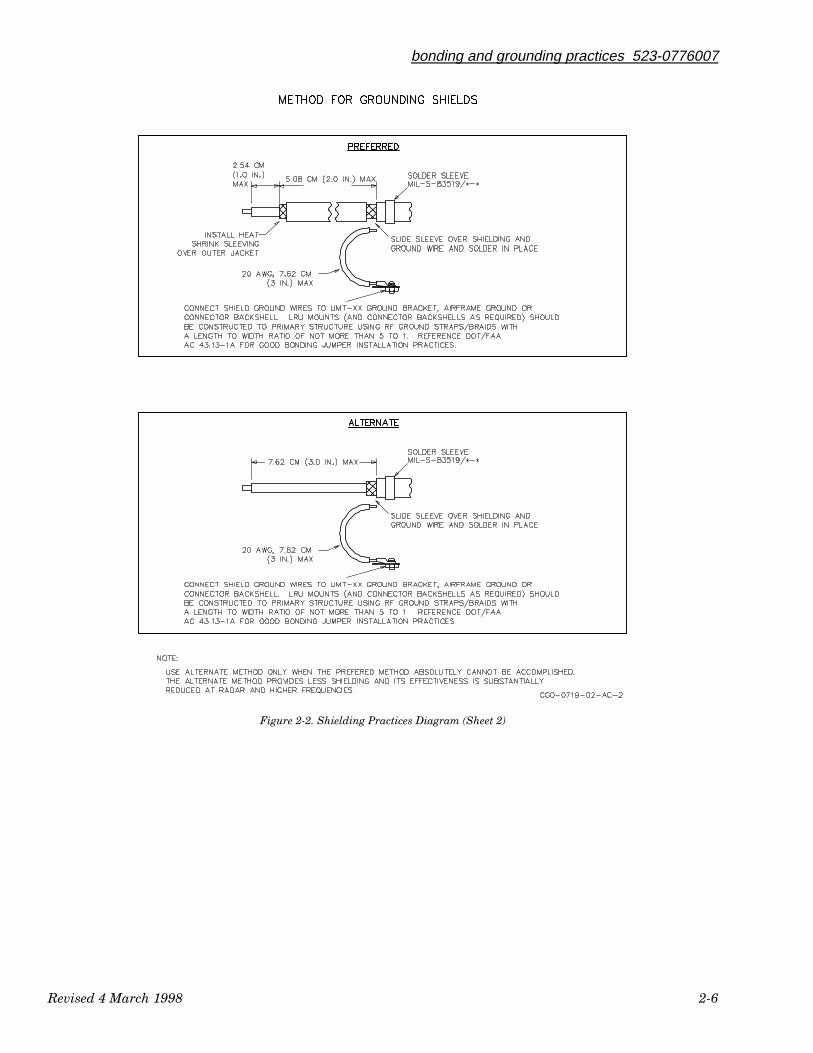
2.2.5 Cable Shielding (Refer to Figure 2-2 and Figure 2-3)
When using shielded wire and coaxial cable the shield must be grounded at both ends. Shield drain wiresshould be 7.62 cm (3.0 in) in length or less and should terminate to chassis ground or airframe ground within3.81 cm (1.5 in) of connector entry to the LRU. In many cases the connector backshell provides a convenientlocation to attach a drain wire. This would require the use of a special circuit. This practice requires ade-quate bonding between masked connector halves and may require the use of conductive spring fingers on theline.
Unless shown specifically in the interconnect drawing or installation data, DO NOT USE THE CONNEC-TOR FUNCTION PINS LABELED “SHIELD” TO TERMINATE WIRING SHIELDS. Doing so could allowthe penetration of high energy interference into the internal areas of an LRU. At the LRU mount, shieldterminations are made directly to the LRU mount/airframe.
The conventional symbols for earth ground and chassis ground are both used for convenience in identifyingpower grounds or returns, and chassis ground terminations. In the actual aircraft installation they wouldelectrically be the same. System power grounds and chassis ground wires must be no greater than the spe-cific lengths and use extremely low impedance bonding paths and materials.
LRU jumper/logic straps should be as short as possible, but no longer than 15.24 cm (6 in). If a particular in-stallation demands a longer length of wire, then single shielded wire should be used with shield of wiregrounded at both ends unless otherwise indicated.
Discrete control functions, discrete valids, and discrete logic lines connected to relays, switches, annunciatorsand other equipment can be single wires and are not required to be twisted-pair wires. The single wires usedfor discrete functions may be open-ended during some operational modes and could act as antennas. Nor-mally, these do not require shielding if they are not directly exposed to the aircraft external environment. Inthe case where a long run (over 30 feet) of unshielded wire is not in a harness with other wiring, it is advis-
Revised 4 March 1998
bonding and grounding practices 523-0776007
2-5
able to shield the wire and ground the shield at both ends. When there is doubt concerning the adequacy ofprotection to any LRU input, the published circuit information for the LRU should be consulted.
Figure 2-2. Shielding Practices Diagram (Sheet 1 of 2)
bonding and grounding practices 523-0776007
Revised 4 March 1998 2-6
Figure 2-2. Shielding Practices Diagram (Sheet 2)

Revised 4 March 1998
bonding and grounding practices 523-0776007
2-7
Figure 2-3. Shielding Treatment, Digital and Analog

bonding and grounding practices 523-0776007
Revised 4 March 1998 2-8
All wiring for AC/DC signals as well as all AC primary power and AC reference power should be shielded,twisted pair wiring with the shield grounded at the source and the load. The AC primary power return wiresare connected at the source end and to ground located at the respective circuit breaker panel or returnsource. The AC primary power low side is normally not grounded at the LRU. AC primary power installa-tions may vary between the various aircraft manufacturers and reference should be made to the aircraftdocumentation. AC reference power returns should be connected at the respective circuit breaker panel orreturn source.
DC primary power returns and chassis ground must be individually connected to LRU mount/airframe usingseparate local termination points for safety purposes. The lengths should not exceed 15.24 cm (6 in). A singlewire may be used for DC primary power if the DC return through airframe ground to the source is less than10 milliohms or the voltage drop between the LRU ground terminal and the primary power grounding pointto airframe does not exceed 0.5 volts during continuous operation of the LRU at a nominal primary voltage of28 volts. Otherwise the installer may use twisted pair wire with power return connected at LRUmount/airframe ground and also connected at the source end to the ground located at the respective circuitbreaker panel or return source. This does not negate the requirement that bonding resistance between anLRU and the airframe be 2.5 milliohms or less.
Wire shields must be grounded at both ends unless otherwise indicated. Shields broken at bulkheads or ter-minal strips/J boxes should be grounded at each end of their section if possible or carried through on sepa-rate pins. (The “suppression” function, which uses coaxial cable, is an exception which requires carryingthrough the shield on pins). Wires used to terminate shields to ground should be 7.62 cm (3.0 in) or less. Allshield termination wires must be connected individually to ground (do not jumper shield to shield with onlyone wire to ground), unless otherwise shown.
Strapping wires added at a unit connector for programming unit internal functions should be 15.24 cm (6.0in) or less where practical. Shield all strapping wires that are longer than 15.24 cm (6.0 in).
Use twisted-shielded-pair wire for AC panel light power. A single wire may be used for DC panel light powerif the airframe is normally used for DC power return. Twisted pair wiring should be used if the airframe isnot used for DC power return. Twisted-shielded-pair wire should be used if pulsed DC is used between unitsfor brightness control.
2.2.6 Cable and Connector Selection
Poorly selected connectors and installed cabling can act as both a noise transmitting and receiving antennaor as undesired primary and secondary windings of coupling transformers, placing interference where itshould not be.
The following must be considered when selecting cable and connectors:
• SIGNAL FREQUENCIES• AUDIO• VIDEO• RF VOLTAGE• POWER LEVELS• SUSCEPTIBILITY TO PICKUP OF NOISE• TOLERABLE LOSS• SIGNAL DEGRADATION
Always use the recommended connector and cable defined in the installation manual or other installation in-structions provided by the manufacturer. All low level analog and data wiring should be shielded, due to
Revised 4 March 1998
bonding and grounding practices 523-0776007
2-9
susceptibility to pickup of noise. When selecting a coax cable, too small a cable may cause excessive lossesand waveform distortion of fast rise time digital pulses. Cable selection should include the highest possiblecopper coverage in the outer braid over the dielectric, to diminish transmission line leakage, and reduce sus-ceptibility to noise pickup. Teflon type dielectric and silver plating the inner and outer conductors greatlyimproves the high frequency capabilities of coax cables.
Connectors must be able to interconnect with very low DC resistance, less than 10 milliohms. Coax connectortypes must be impedance matched to the system impedance.
Very low level signals (-100 dBm) require careful selection of connectors and cable. Ferro-magnetic materialssuch as iron, stainless steel, cobalt and nickel, can cause the generation of intermodulation or nonlinear dis-tortion. Even minute amounts of these materials can generate noise levels high enough to mask the low levelsignal. Connector base material should be brightly plated with copper, followed by a plated gold finish forprotection and minimum contact resistance. Copper clad wire and stainless steel base materials for connec-tors should not be used in low level signal applications.
Connector contact base material may be brass, but the spring retention material should be beryllium copper.Brass will lose its contact pressure and the connection will become noisy or fail.
For installation design, wire and cable selection may require but not be limited to options such as twistedpairs, shielded wire, coax, triax, twinax and foil shields.
All single-ended low level analog or data circuits should be interconnected using shielded wire or cable toprotect against magnetic (inductive) and electric (capacitive) stray fields. Many units use balanced circuitryfor the data and low level inputs and require twisted shielded pair wiring. Triaxial cable in place of coaxialcable may be used for antenna to LRU antenna port interconnection where better protection of the antennainput is required. Wires and cables that provide higher than normal attenuation, such as the Raychem Elec-troloss filter line, are available but an analysis of the installation should be made as to the level of protectionrequired before using the higher attenuation cable. Any installed spare wires or unused open-ended cablemay be left open for convenience. One method that is employed to reduce overall susceptibility of a cablebundle to high energy, particularly lightning, is to add a wire into the cable that is grounded at both ends.This provides a low impedance path for the interference, thereby reducing the level induced on adjacent con-ductors.
The use of shielded wire with the shield grounded at both ends is used to raise the lightning damage immu-nity of LRU input; the shielding acting as a layer of protection to electric and magnetic fields for the signalconductor. Engineering normally designates which circuits require this protection and ensures that this isshown on the interconnect drawing.
2.2.7 Cable Routing
From an RF viewpoint an all metal airplane is a loss wave guide, containing wire bundles routed in variousdifferent locations which connect to electrical circuits and electronic equipment. The fuselage provides alimited degree of protection (20-25 dB) as a shield. Additional protection can be achieved by routing ca-ble/wire bundles as close as possible to the aircraft skin thereby producing a transmission line effect.
Where shielded wires are routed between different sections of the aircraft, such as from equipment rack tothe cockpit panel, the shields should be grounded to the airframe at multiple locations if at all possible. Thisenhances the effectiveness of the shield by both confining and distributing the shield currents and reducingthe electrical potential along the shield, particularly in the case of lightning effects.
Protection methods against interference generated within the aircraft, referred to as electromagnetic com-patibility (EMC), and against interference generated external to the aircraft must be evaluated as a whole.For example, the greater the number of wires in a bundle and the tighter the grouping of the wires, the bet-
bonding and grounding practices 523-0776007
Revised 4 March 1998 2-10
ter the protection against external radiation sources and against lightning effects. Conversely, to preventcross-talk and the induction of switching transients into low level circuits, wires are loosely bundled. In addi-tion, the power, signal and high current drive interconnect wires may also be separated from each other. Thelower the system signal voltage, the greater is the susceptibility to outside interference. This is why low levelsignal lines are spaced separately from high current and high voltage cables. To minimize the coupling be-tween cables, physical separation is the best solution. Typical wire bundle separation might require group-ings such as system 1 power, system 1 digital I/O, system 1 analog I/O and system 1 RF. Ideally these system1 wire bundles would be on the left side of the aircraft along with associated electronics and all system 2 wirebundles and electronics would be located on the right side of the aircraft. Requirements will vary with indi-vidual installations and may need more or less separation. In general, all of the wires used to form the inter-connection harness for each side of the Collins avionics systems. including the primary power line, can begrouped together. This improves the immunity to external interference sources.
Do not bend coaxial cable tighter than manufacturer's recommendations as cable discontinuities may result.Care must be taken to route cables for critical functions separately from cables for redundant systems, e.g.,attitude interconnect wires #1 and #2 systems must be separated.
2.2.8 Maintenance Considerations
The certification authorities have indicated that those measures to protect the avionics system against theeffects of HIRF and lightning will eventually be subject to maintenance requirements. However, specificitems to be inspected or measured have as yet to be agreed upon. Until such time as specific maintenanceitems are addressed by regulation, maintenance of Collins avionics systems installations which are installedin accordance with these guidelines and which are operating correctly, will be “On Condition” maintenance.Therefore, there will not be additional maintenance required except for normal visual inspections for damageduring routine aircraft inspections.
2.2.9 References
The following official documents should be referred to for additional or expanded information:
a. FAA Advisory Circular 43.13-1A, Chapter 11, Electrical Systems (refer to appendix).b. FAA Advisory Circular 20-1309, System Design and Analysisc. FAA Advisory Circular 20-136, Protection of Aircraft Electrical/Electronics Systems Against the Indirect
Effects of Lightning. 2.2.10 Shield Treatment of Microphone Jacks
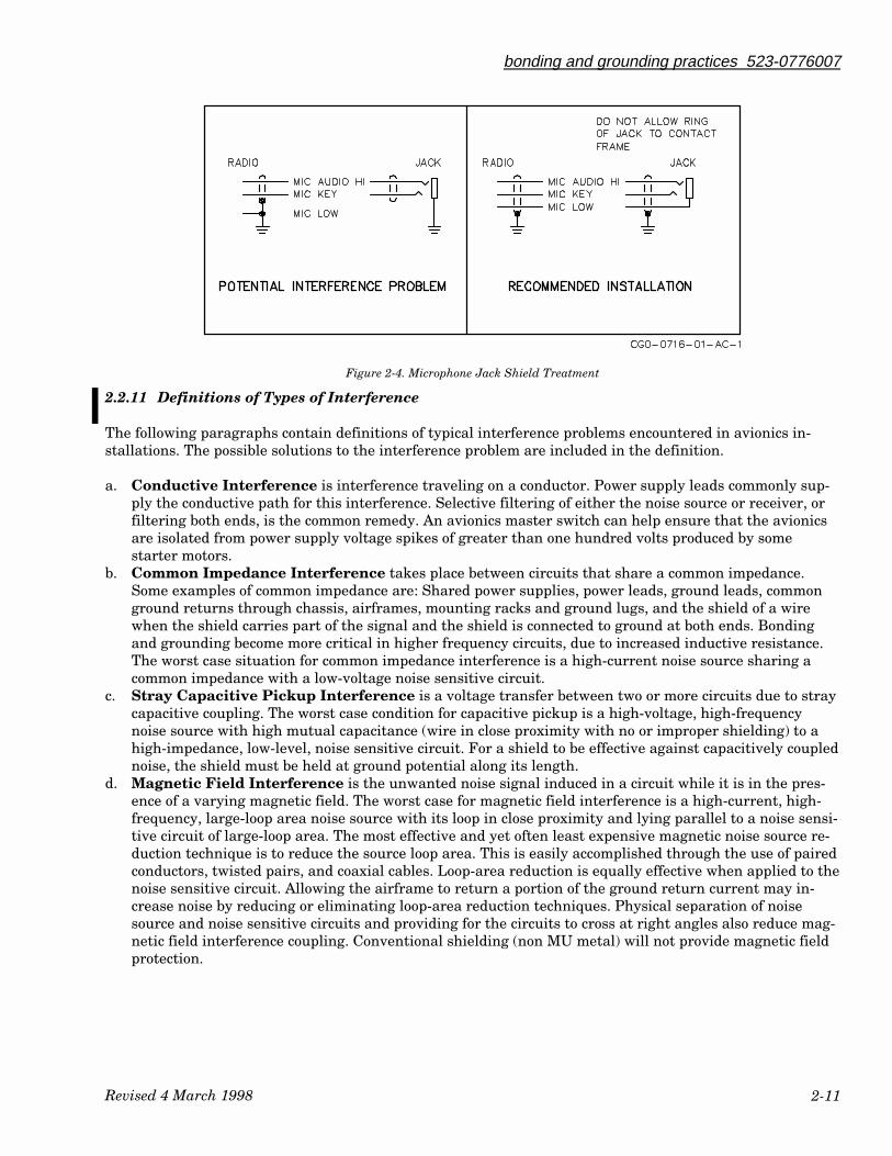
Figure 2-4 illustrates a common microphone jack installation with potential interference problems, alongwith a recommended installation that eliminates the problems. Although the problem installation is pro-tected from capacitive noise, it is open to both magnetic and common impedance problems. The airframeserves as the common impedance ground return for the MIC AUDIO LOW along with many other aircraftappliances. The MIC AUDIO HI makes a loop with the airframe. The loop's area depends upon the routing ofthe MIC cable. It may be large and is capable of developing noise currents from magnetic fields. A compro-mise is to allow the shield to be used as a conductor for the MIC AUDIO LOW. This reduces the loop area, al-though not as well as a twisted pair. Also the capacitively coupled noise returning to ground along the shieldwill share the common impedance of the shield with the MIC AUDIO LOW. The recommended installationdiagrammed in Figure 2-4 eliminates both magnetic and common impedance problems.
BUSINESS AND REGIONAL SYSTEMSINSTALLATION PRACTICES MANUAL
Temporary Revision 1523-0775254-01311A May 26/00
Installation Practices Manual
INSTALLATION MANUAL (523-0775254, 3RD EDITION, DATED MAR 4/98)
TEMPORARY REVISION NO. 01Insert facing page 2-10.
Subject: Change to Advisory Circular AC 43.13-1A.
Advisory Circular AC 43.13-1A has been revised and is now labeled AC 43.13-1B, dated 9/8/98.
In paragraph 2.2.9.a should read as follows:
a. FAA Advisory Circular 43.13-1B Chapter 11, Aircraft Electrical Systems (refer toappendix).
Page 2
Revised 4 March 1998
bonding and grounding practices 523-0776007
2-11
Figure 2-4. Microphone Jack Shield Treatment
2.2.11 Definitions of Types of Interference
The following paragraphs contain definitions of typical interference problems encountered in avionics in-stallations. The possible solutions to the interference problem are included in the definition.
a. Conductive Interference is interference traveling on a conductor. Power supply leads commonly sup-ply the conductive path for this interference. Selective filtering of either the noise source or receiver, orfiltering both ends, is the common remedy. An avionics master switch can help ensure that the avionicsare isolated from power supply voltage spikes of greater than one hundred volts produced by somestarter motors.
b. Common Impedance Interference takes place between circuits that share a common impedance.Some examples of common impedance are: Shared power supplies, power leads, ground leads, commonground returns through chassis, airframes, mounting racks and ground lugs, and the shield of a wirewhen the shield carries part of the signal and the shield is connected to ground at both ends. Bondingand grounding become more critical in higher frequency circuits, due to increased inductive resistance.The worst case situation for common impedance interference is a high-current noise source sharing acommon impedance with a low-voltage noise sensitive circuit.
c. Stray Capacitive Pickup Interference is a voltage transfer between two or more circuits due to straycapacitive coupling. The worst case condition for capacitive pickup is a high-voltage, high-frequencynoise source with high mutual capacitance (wire in close proximity with no or improper shielding) to ahigh-impedance, low-level, noise sensitive circuit. For a shield to be effective against capacitively couplednoise, the shield must be held at ground potential along its length.
d. Magnetic Field Interference is the unwanted noise signal induced in a circuit while it is in the pres-ence of a varying magnetic field. The worst case for magnetic field interference is a high-current, high-frequency, large-loop area noise source with its loop in close proximity and lying parallel to a noise sensi-tive circuit of large-loop area. The most effective and yet often least expensive magnetic noise source re-duction technique is to reduce the source loop area. This is easily accomplished through the use of pairedconductors, twisted pairs, and coaxial cables. Loop-area reduction is equally effective when applied to thenoise sensitive circuit. Allowing the airframe to return a portion of the ground return current may in-crease noise by reducing or eliminating loop-area reduction techniques. Physical separation of noisesource and noise sensitive circuits and providing for the circuits to cross at right angles also reduce mag-netic field interference coupling. Conventional shielding (non MU metal) will not provide magnetic fieldprotection.
bonding and grounding practices 523-0776007
Revised 4 March 1998 2-12
2.3 CONTROL SURFACE BONDING
A braided electrical jumper strap is normally used to bond a control surface to the aircraft surface. Adding orrepairing bonding jumpers or static discharge wicks to an aircraft control surface is critical to the safety offlight.
The work must be inspected and signed off by a certified mechanic. In determining the best location for thebonding jumper, consider the movement of the control surface to be bonded. Clean off any nonconductive ma-terial such as zinc chromate, paint, grease, oil, etc from the bonding areas. Connect bonding jumper to thecontrol surface. Connect the opposite end to the aircraft surface.
Refer to Figure 2-1 for a view of a typical grounding stud installation. Check the movement of the controlsurface. The jumper must not restrict the movement of the control surface.
2.3.1 Bonding Aluminum Surfaces
The first step in preparing two surfaces for bonding is to clean the surfaces. All nonconductive elements suchas zinc chromate, paint, grease, oil, etc must be removed from the bonding surfaces. The area should bebrushed clean or sanded with very fine sandpaper. This should remove any aluminum oxide from the sur-face. Use caution not to remove excessive amounts of aluminum. Wipe off the cleaned surfaces with a cleancloth and 1,1,1 Trichloroethane. The bare aluminum may be treated with Alodine 1200S, CPN 005-1157-010(please note: the quantity for Alodine 1200S under CPN 005-1157-010 is one gallon) or Iridite 14-9 or otherconductive material. After applying Alodine, allow time for all the surfaces to dry (1 hour max).
Warning
When using flammable materials for cleaning purposes, observe all fire precautions. The materi-als should be used outside or in a ventilated booth provided with explosion-proof electricalequipment and exhaust fan having sparkproof blades.
The mating surfaces must be smooth and contoured so that the mating surface area is in actual contact. Af-ter completion of the bonding, refinish the area from which the protective coating has been removed with itsoriginal finish or other suitable protective finish within 24 hours. In no case shall full refinishing be delayedmore than seven days after removal of the finish.
2.3.2 Bond Testing
The following test methods are very useful in assuring adequate electrical bonding between surfaces. Indi-vidual bonds should have a resistance of less than 0.75 milliohms, and should normally measure 0.25 mil-liohms or less. The simplest method is to employ a Biddle (milliohm) meter device and measure for bond re-sistance as shown in Figure 2-5. If a Biddle meter on the line is unavailable, a voltage drop test may beperformed as follows:
a. Securely (bolt) connect Z and Y as indicated in Figure 2-6.b. The contact resistance at Z and Y will not be included in the millivolt measurement circuit if the leads P
and Q are not connected across the connections at Z and Y.c. Adjust the power supply for the required 10 amps.d. Connect the millivoltmeter across the bond and read the voltage drop.e. The millivolt reading should be nominally less than 2.5 millivolts; anything greater than 7.5 millivolts is
a poor bond. (7.5 millivolts at 10 amps means the bond has 0.75 milliohm of resistance).
BUSINESS AND REGIONAL SYSTEMSINSTALLATION PRACTICES MANUAL
Temporary Revision 1523-0775254-01311A May 26/00
Installation Practices Manual
INSTALLATION MANUAL (523-0775254, 3RD EDITION, DATED MAR 4/98)
TEMPORARY REVISION NO. 01Insert facing page 2-13.
Subject: Change to Advisory Circular AC 43.13-1A.
In the last sentence on the page, Advisory Circular AC 43.13-1A has been revised and is nowlabeled AC 43.13-1B, dated 9/8/98.
Page 3

Revised 4 March 1998
bonding and grounding practices 523-0776007
2-13
2.3.3 Honeycomb Shelf Bonding
Honeycomb bonding requires consideration of the two shelf surfaces. The top and bottom surfaces are con-nected to the honeycomb core by nonconductive adhesive. To obtain a bond between the top and bottom sur-faces, a bonding rivet or strap is required. A bolt and strap can also be used.
Refer to Figure 2-7 for a diagram on bonding a honeycomb shelf. It is recommended that the shelf be bondedin two or more places at opposite ends of the shelf. Follow the bonding instructions in paragraph 2.1 for alu-minum shelf. Additional information on bonding is available in FAA AC 43.13-1A located in the appendixsection of this manual.

bonding and grounding practices 523-0776007
Revised 4 March 1998 2-14
Figure 2-5. Preferred Bond Testing Diagram
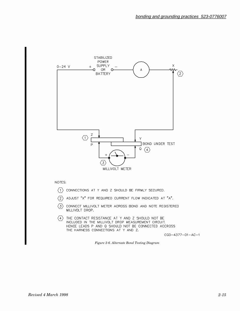
Revised 4 March 1998
bonding and grounding practices 523-0776007
2-15
Figure 2-6. Alternate Bond Testing Diagram
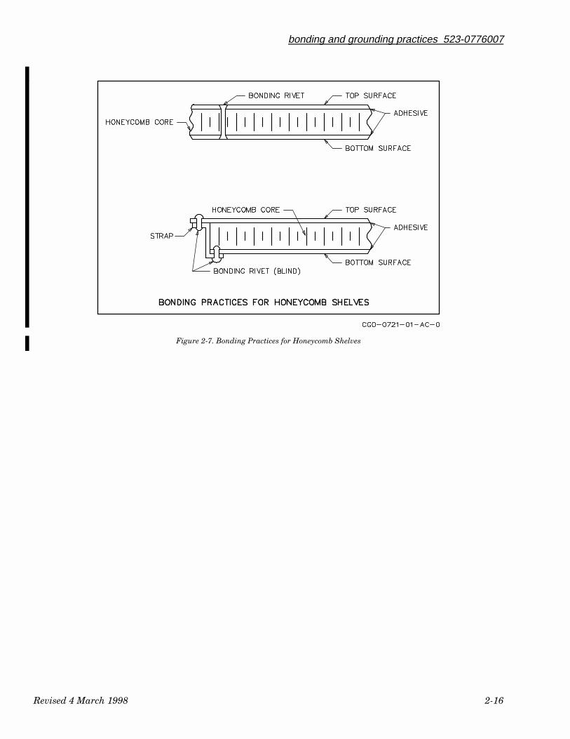
bonding and grounding practices 523-0776007
Revised 4 March 1998 2-16
Figure 2-7. Bonding Practices for Honeycomb Shelves

3.1 INTROUCTION ....................................................................................................................................................... 3-1
3.2 CONTROLS.............................................................................................................................................................. 3-13.2.1 Variable Controls ............................................................................................................................................................3-13.2.2 Step Controlled Dimming...............................................................................................................................................3-1
3.3 ANNUNCIATORS.................................................................................................................................................... 3-23.3.1 Annunciator Color...........................................................................................................................................................3-23.3.2 Annunciator Location .....................................................................................................................................................3-23.3.3 Annunciator Dimming ....................................................................................................................................................3-23.3.4 Annunciator Legends......................................................................................................................................................3-3
3.4 INSTRUMENT DIMMING...................................................................................................................................... 3-33.4.1 Automatic Dimming........................................................................................................................................................3-33.4.2 Connection to Dimming Bus...........................................................................................................................................3-3
523-0776008-0031183rd Edition, 4 March 1998
Installation Practices Manual
NOTICE: This section replaces second edition dated 6 March 1992.
Dimming and Annunciators
Paragraph Page
Table of Contents

List of Effective Pages *The asterisk indicates pages changed, added, or deleted by the current change.
Page No Issue
* Title .......................................... 4 Mar 98* List of Effective Pages.............. 4 Mar 98* 3-1 thru 3-8................................ 4 Mar 98
Record of RevisionsRETAIN THIS RECORD IN THE FRONT OF THE MANUAL. ON RECEIPT OFREVISIONS, INSERT REVISED PAGES IN THE MANUAL, AND ENTER DATEINSERTED AND INITIALS.
REVNO
REVISIONDATE
INSERTIONDATE/BY
SB NUMBERINCLUDED
REVNO
REVISIONDATE
INSERTIONDATE/BY
SB NUMBERINCLUDED
1st Ed 22 Mar 90 None
2nd Ed 6 Mar 92 None
3rd Ed 4 Mar 98 None
section IIIdimming and annunciators
Revised 4 March 1998 3-1
3.1 INTRODUCTION
Paragraph 3.2 covers information on controlling the lighting of the avionics located in the cockpit. Most air-craft installations have either a +28-V dc, +5-V dc, or a +5-V ac light dimmer supply. Information on annun-ciators is located in paragraph 3.3.
3.2 CONTROLS
Determine the lighting requirements of the equipment to be installed. Annunciator lighting is normallyconnected to a bright/dim power supply. Figure 3-1 is a view of a typical panel dimming control layout.Each aircraft type has a unique lighting scheme. Consult the aircraft manufacturer for additional informa-tion.
3.2.1 Variable Controls
Variable lighting controls are generally used with instrumentation panel legends and in some cases, digitalread-outs. In each instance the installer is faced with a different problem of dimming control.
Instrument lighting should be such that it is localized. All the instruments in the pilot’s panel should be con-trolled by a single control if possible, as should the copilot’s panel, central panel, etc. Where it is not possibleto control avionics and flight instruments with the same control, the same method of localized dimmingshould be used. The level of instrumentation dimming should be consistent (example: avionics and aircraftinstrumentation should dim approximately the same levels).
Panel and legend lighting should follow the same scheme as instrumentation and be separate from it. Again,avionics panel and legend dimming should be consistent with the aircraft dimming scheme.
Digital readout dimming presents a special case. In most cases, avionics readouts are advisory in nature andonly used as a reference. These readouts should be separately controlled as that each readout is dimmedseparately o in related groups. Although the readouts are not essential for flight, they should be readableunder normal nighttime flying conditions at all times. The readouts should never be installed so that theycan be completely extinguished.
3.2.2 Step Controlled Dimming
This type of dimming is used mostly for annunciators but may be used to dim other advisory lighting. Con-trol for this scheme of lighting may be manual or semiautomatic. When the manual method is used, itshould be clearly labeled and easily accessible during flight. When semiautomatic dimming is used, it shouldbe explained in the Flight Manual and tied to a circuit that is activated for night flying. As always, dimmingshould be consistent with other aircraft lighting.
Lighting of annunciators can be a day/night switch that changes the voltage level to the dim bus. Annuncia-tor dimmer power can be supplied from a +28-V dc, +5-V dc, or +5-V ac source. The voltage level in the night

dimming & annunciators 523-0776008
Revised 4 March 1998 3-2
position of the day/night switch is nominally one-half th supplied voltage. The night dimming voltage level othe annunciator night brightness should be set to the preference of the night flying crew.
3.3 ANNUNCIATORS
The following paragraphs provide information on the color, location, legends, and dimming of annunciators.Annunciators provide information to the pilot/copilot. This information could be a warning, alert, or nor-mal/reminder indications.
3.3.1 Annunciator Color
The lens color is normally as follows:
Red: Normally used as a failure warning and required immediate attention.
Amber: Normally used for “arm” and alert functions.
Green: Normally used as information, reminder, or to display automatic switching functions of autopilotand flight director modes.
Blue and white lenses are also used, but the blue is hard to notice in a bright cockpit while white is too harshin a dark cockpit.
3.3.2 Annunciator Location
Location is critical because the pilot/copilot must see or notice the annunciator at a glance, yet not be dis-tracted at critical moments. The annunciators are normally grouped above or alongside their associatedunit. If the annunciator is a warning or caution/alert annunciator, the location should be within the pilot’sview of the altimeter/airspeed instruments. When laying out an instrument panel, don’t forget the viewingangle. Keep in mind the different heights of pilots; a tall pilot’s view of the annunciator may be blocked bythe glareshield.
3.3.3 Annunciator Dimming
Normal dimming control of annunciators is accomplished by step dimming. Refer to paragraph 3.1.2 for ad-ditional information on step dimming. Points to remember are those “sneak” circuits that go back throughlamp filaments to ground or to a voltage source causing “dim” annunciators or interlock to exist.
A voltage source turned off may appear to the circuit as ground potential. It may be necessary to select re-sistors to obtain a more even intensity in the dim position of the annunciators.
Determine the type of output that is supplied from the unit. Some units supply an output of +28 V dc whenan annunciation is required. Some units supply an output of a ground when the annunciation is required.Refer to the unit’s installation for the information on the annunciator output specification. A difference ofoutput specifications creates a problem for dimming of the annunciators.
The outputs that supply +28 V dc annunciator power require a voltage drop when in the dim (night) position.This dimming can be accomplished in a variety of ways. The current required to annunciate the legend isthe first consideration. The current capability of the dimmer circuit must be within the current require-ments o the annunciator. Next, determine the method of dimming desired. Does the customer desire morethan one dimming position for the aircraft annunciators? With the use of a dropping resistor and a voltageregulator, the voltage can be reduced to any desired level. The current capabilities of the annunciator needto be considered. The annunciator outputs from the unit normally have a limited current capability. Do not
dimming & annunciators 523-0776008
Revised 4 March 1998 3-3
exceed the current limit of the unit’s annunciator output. If additional current is required, a relay orswitching device should be used.
Diode isolation between the annunciator dim bus and the annunciator eliminates the feedback problems.Most aircraft manufacturers provide an accessory box that supplies the step dimming voltage output. Referto the aircraft wiring diagrams from the aircraft manufacturer for the information on the dimming circuits.
Annunciators can be purchased with the lens colors and legends needed from the following:
Stacoswitch1139 Baker St.Costa Mesa, CA92626Telephone: (714) 549-3041
Aerospace Optics3201 Sandy Ln.Ft. Worth, TX76112Telephone: (817) 451-1141
Use annunciators similar to the annunciators that have been used previously. Commonality between an-nunciators in the instrument panels will look symmetrical. Consult the annunciator vendor for additionaloptions available. The annunciators can also supply switching options. Take careful consideration of contactcurrent capabilities of the switches involved. Also consider the current requirements of the lamps in the an-nunciators.
3.3.4 Annunciator Legends
Annunciator legends provide information on what the annunciation is warning, alerting, or informing. It isimportant to keep the wording or lettering as brief as possible while still retaining the intent of the annun-ciator. Table 3-1 is a list of popular colors and abbreviations for some typical legends.
3.4 INSTRUMENT DIMMING
The following paragraphs describe examples on interconnecting units mounted in the instrument panel.
3.4.1 Automatic Dimming
Most controls manufactured today, such as CTL-X2’s, have light sensors to control the dimming of the dis-play. This automatic dimming level can be tied together with other controls to provide a uniform displaybrightness.
Figure 3-2 is an example of the options available on interconnecting CTL-X2’s together. The level ofautomatic dimming may vary between controls. By connecting the controls together (connect pin n on CTL-X2’s and pin 10 on IND-42( )’s together, any display brightness differences will be minimized. Check com-patibility of automatic dimming voltage output. Some controls/indicators use different voltage levels to rep-resent different levels. Refer to the control’s or indicator’s installation manual for additional information.
3.4.2 Connection to Dimming Bus
Aircraft installations normally have dimmer bus junction terminals located behind the instrument panel.These terminals provide a central point to connect the dimmer power supply and branch out to the appropri-ate controls and indicators. In most cases there are four or five junction blocks, one for each instrumentpanel and day/night junction block. These junction terminals also allow the dimmer power supplies to be lo-
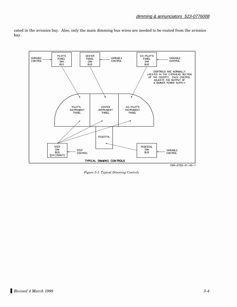
dimming & annunciators 523-0776008
Revised 4 March 1998 3-4
cated in the avionics bay. Also, only the main dimming bus wires are needed to be routed from the avionicsbay.
Figure 3-1. Typical Dimming Controls

dimming & annunciators 523-0776008
Revised 4 March 1998 3-5
Table 3-1. Annunciator Legend Abbreviations and Colors.
ABBREVIATIONS ANNUNCIATOR NAME COLOR
AIL TRIMALTALT SELALT SELAP
AP FAILAP TRIMAP XFRATTAPPR
COMP (CMPR)B/LCOMP (HDG)D/RELEV TRIM
GAGS ARMGS CAPTGS LIMITGS DEV
HDGIASLIN DEVLIN DEV OFFMACH
NAVNAV/LOCNAV ARMNAV CAPTPITCH
TURBV/LV/L ARMV/L CAPTVS
V NAVWPTYDYD DISYD FAIL
Aileron out of trimAltitudeAltitude selectAltitude selectAutopilot disengage
Autopilot failureAutopilot trim failureAutopilot transferAttitude (comparator)Approach mode
Comparator warnBack course localizerCompass (comparator)Dead reckoningElevator out of trim
Go-aroundGlideslope armGlideslope captureGlideslope limit (comparator)Glideslope deviation
Heading modeIndicated airspeed modeLinear deviation modeLinear deviation mode offMach airspeed hold mode
Navigation modeNavigation/localizer modeNavigation arm modeNavigation capture modePitch hold mode
Turbulence modeVOR-localizer modeVOR-localizer arm modeVOR-localizer capture modeVertical speed hold mode
Vertical navigation modeWaypoint alertYaw damper modeYaw damper disengagedYaw damper failure
AmberGreenAmber (arm)Green (capture or trackAmber (flashing)
RedRedGreenAmberGreen
Red or amberGreenAmberGreen or amberAmber
GreenAmberGreenAmberAmber
GreenGreenGreenGreen or amberGreen
GreenGreenAmberGreenGreen
GreenGreenAmberGreenGreen
GreenAmberGreenAmberRed
VERT Vertical mode Green

dimming & annunciators 523-0776008
Revised 4 March 1998 3-6
This page intentionally blank.
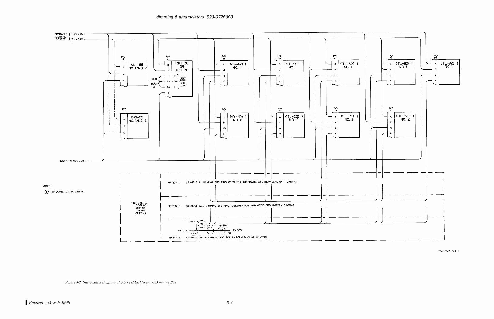
dimming & annunciators 523-0776008
Revised 4 March 1998 3-7
Figure 3-2. Interconnect Diagram, Pro Line II Lighting and Dimming Bus

dimming & annunciators 523-0776008
Revised 4 March 1998 3-8
This page intentionally blank.

4.1 INTRODUCTION .................................................................................................................................................................................. 4-1
4.2 ANTENNA LOCATION......................................................................................................................................................................... 4-14.2.1 Comm Antenna Location ..................................................................................................................................................................... 4-14.2.2 VHF Comm and GPS Antenna Spacing Guidelines............................................................................................................................. 4-14.2.3 ADF Antenna Location ........................................................................................................................................................................ 4-24.2.4 Nav Antenna Location ......................................................................................................................................................................... 4-34.2.5 L-Band Antenna Location.................................................................................................................................................................... 4-34.2.6 Radio Altimeter Antenna Location ...................................................................................................................................................... 4-34.2.7 Radar Antenna Location....................................................................................................................................................................... 4-3
4.3 ANTENNA SELECTION ...................................................................................................................................................................... 4-44.3.1 Comm Antenna Selection..................................................................................................................................................................... 4-44.3.2 ADF Antenna Selection ....................................................................................................................................................................... 4-44.3.3 Nav Antenna Selection......................................................................................................................................................................... 4-44.3.4 L-Band Antenna Selection ................................................................................................................................................................... 4-4
4.4 FACTORS AFFECTING VHF COMMUNICATION .......................................................................................................................... 4-54.4.1 Line-of-Sight Range............................................................................................................................................................................. 4-54.4.2 Radiated Power Output/Received Power ............................................................................................................................................. 4-54.4.3 Free Space Loss.................................................................................................................................................................................... 4-64.4.4 Antenna Factors ................................................................................................................................................................................... 4-64.4.5 Multipath.............................................................................................................................................................................................. 4-64.4.6 Locally Generated Noise or Interference.............................................................................................................................................. 4-7
4.5 BONDING, CABLE BUNDLING, AND CORROSION PROTECTION............................................................................................. 4-74.5.1 Antenna Bonding ................................................................................................................................................................................. 4-74.5.1.1 RF Strap for Reducing RF Interference............................................................................................................................................. 4-84.5.1.2 Bonding on Composite, Fiberglass, or Fabric Skins ......................................................................................................................... 4-84.5.2 Cable Bonding ..................................................................................................................................................................................... 4-94.5.3 Corrosion Protection ............................................................................................................................................................................ 4-9
4.6 ANTENNA SEALANT........................................................................................................................................................................... 4-9
4.7 ANTENNA SKIN MAPPING .............................................................................................................................................................. 4-10
523-0776009-0031183rd Edition, 4 March 1998
Installation Practices Manual
NOTICE: This section replaces second edition dated 6 March 1992.
Antenna Practices
Paragraph Page
Table of Contents

List of Effective Pages *The asterisk indicates pages changed, added, or deleted by the current change.
Page No Issue
* Title ........................................... 4 Mar 98* List of Effective Pages............... 4 Mar 98
*4-1 thru 4-10 .............................. 4 Mar 98
Record of RevisionsRETAIN THIS RECORD IN THE FRONT OF THE MANUAL. ON RECEIPT OFREVISIONS, INSERT REVISED PAGES IN THE MANUAL, AND ENTER DATEINSERTED AND INITIALS.
REVNO
REVISIONDATE
INSERTIONDATE/BY
SB NUMBERINCLUDED
REVNO
REVISIONDATE
INSERTIONDATE/BY
SB NUMBERINCLUDED
1st Ed 22 Mar 90 None
2nd Ed 6 Mar 92 None
3rd Ed 4 Mar 98 None
section IVantenna practices
Revised 4 March 1998 4-1
4.1 INTRODUCTION
The following paragraphs provide information on the installation of avionics antennas. The location of theantenna greatly affects the efficiency of the antenna. Antenna mounting practices and antenna location re-quirements are included. The importance of a good antenna installation cannot be over-emphasized, it is es-sential if optimum system performance is to be obtained.
4.2 ANTENNA LOCATION
The location of the antenna for each type of equipment requires specialized information. The following para-graphs contain information for each equipment type, starting with comm equipment.
4.2.1 Comm Antenna Location
Maintain maximum spacing between comm antennas and nav antennas. It is essential that all antennas bebonded to the aircraft skin. Failure to do so can create VHF RFI problems in autopilot systems and other air-craft equipment, and comm to nav interference.
A line-of-sight path should be maintained between the receiving station and the VHF transmitter antenna. Abottom-mount antenna can be used for en route operations and a top-mounted antenna can be tied to theother comm for ground communications. This arrangement also gives a higher degree of antenna isolationwhich will help to minimize comm to comm interference.
The top antenna should be mounted at the highest point above the cabin to ensure a good radiation pattern.Typically the top-mounted antenna should be connected to Comm 2 and the belly antenna to Comm 1. Thisarrangement provides good communications while on the ground via Comm 2 and when airborne via Comm1.
If it is absolutely necessary to mount both antennas on the same side (both on top or bottom) of the aircraft,make sure the separation between antennas is a minimum of 1.2 meters (4 ft). The comm antennas can in-teract with each other if mounted too close together, and produce large directional "dead spots".
Keep vhf comm antennas at least 1 meter (3 ft) away from VOR antennas. Interaction between the two canresult in VOR needle movement during comm transmission.
4.2.2 VHF Comm and GPS Antenna Spacing Guidelines
This information provides installed equipment spacing guidelines to address VHF Comm and GPS mutualinterference (refer to Figure 4-1).
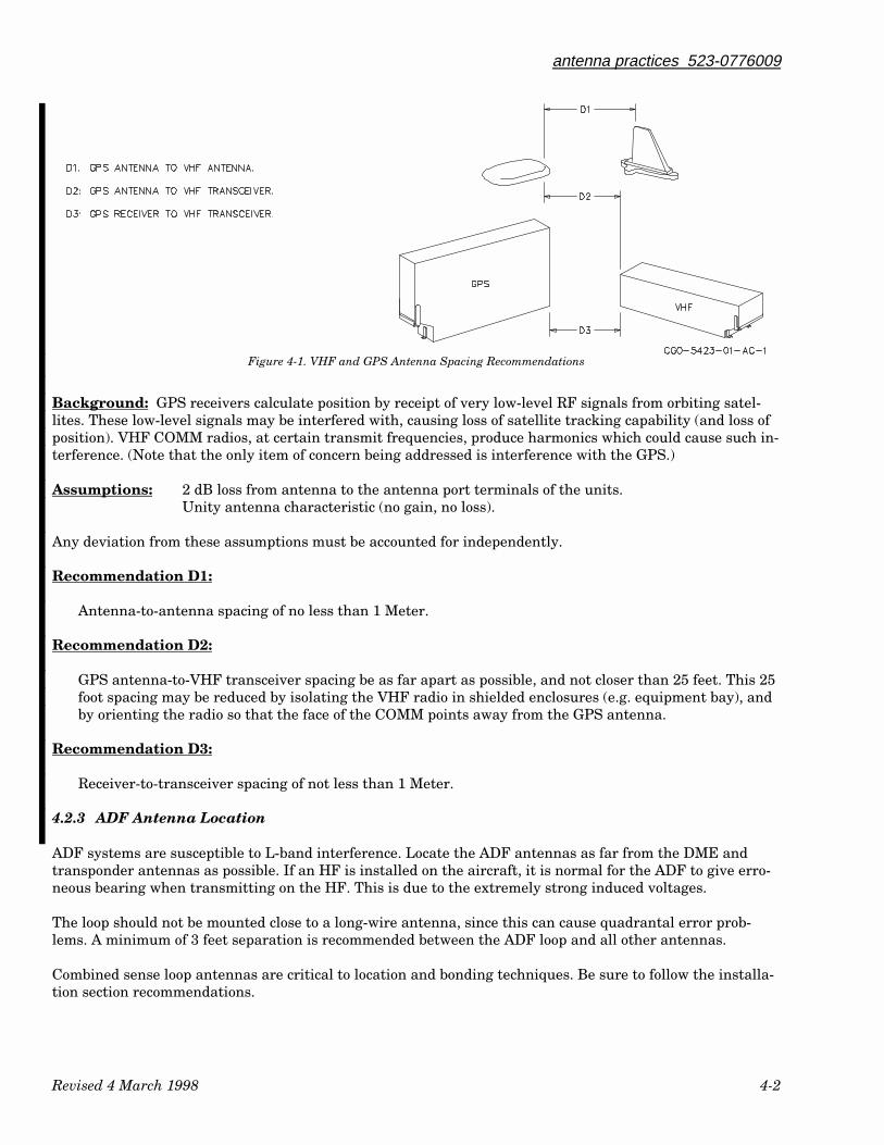
antenna practices 523-0776009
Revised 4 March 1998 4-2
Figure 4-1. VHF and GPS Antenna Spacing Recommendations
Background: GPS receivers calculate position by receipt of very low-level RF signals from orbiting satel-lites. These low-level signals may be interfered with, causing loss of satellite tracking capability (and loss ofposition). VHF COMM radios, at certain transmit frequencies, produce harmonics which could cause such in-terference. (Note that the only item of concern being addressed is interference with the GPS.)
Assumptions: 2 dB loss from antenna to the antenna port terminals of the units.Unity antenna characteristic (no gain, no loss).
Any deviation from these assumptions must be accounted for independently.
Recommendation D1:
Antenna-to-antenna spacing of no less than 1 Meter.
Recommendation D2:
GPS antenna-to-VHF transceiver spacing be as far apart as possible, and not closer than 25 feet. This 25foot spacing may be reduced by isolating the VHF radio in shielded enclosures (e.g. equipment bay), andby orienting the radio so that the face of the COMM points away from the GPS antenna.
Recommendation D3:
Receiver-to-transceiver spacing of not less than 1 Meter.
4.2.3 ADF Antenna Location
ADF systems are susceptible to L-band interference. Locate the ADF antennas as far from the DME andtransponder antennas as possible. If an HF is installed on the aircraft, it is normal for the ADF to give erro-neous bearing when transmitting on the HF. This is due to the extremely strong induced voltages.
The loop should not be mounted close to a long-wire antenna, since this can cause quadrantal error prob-lems. A minimum of 3 feet separation is recommended between the ADF loop and all other antennas.
Combined sense loop antennas are critical to location and bonding techniques. Be sure to follow the installa-tion section recommendations.
antenna practices 523-0776009
Revised 4 March 1998 4-3
ADF antennas are sensitive to other noise interferences such as alternator, generator, strobe, inverter, andmotor noises. The antenna location should be located to minimize this type of interference for optimal ADFperformance.
4.2.4 Nav Antenna Location
The nav antenna is normally located in the tail section of the aircraft. If an external balun is used in the navantenna system, it should also be bonded to the aircraft skin. Comm to nav interference has been caused bythe balun itself being susceptible to RFI. The cure in some cases has been to wrap the balun in a conductivematerial such as metallic tape.
4.2.5 L-Band Antenna Location
It is important that adequate isolation be provided between two DME antennas, or a DME and a trans-ponder antenna to prevent receiver front-end damage. It is possible, with the use of DME Y-channels, for oneDME to transmit directly on the frequency of a second DME as well as the receiver frequency of the trans-ponder. The transponder can also transmit directly on the receiver frequency of the DME. Minimum isola-tion of 40 dB between L-band antenna isolation plus cables loses. A separation of 4 feet between L-band stubantennas, on a common ground plane, provides about 32 dB of isolation. The isolation increases 6 dB for eachdoubling of the separation in distance; that is, 38 dB for 8 feet, 44 dB for 16 feet, etc.
In determining cable length, allow sufficient length so that bends will have a minimum of 75-mm (3-in) ra-dius. Maximum cable length for RG-214/U is 9 m (30 ft) and for RG-142B/U, 7 m (22 ft).
Placement of the L-band antenna should be carefully planned and installation instruction followed closely toensure optimum performance of the system. Random placement of the L-band antenna may result in aircraftantenna shielding causing dead spots in normal flight attitude. Select a mounting area well removed fromprojections such as propellers, landing gear, and engines. Mount the antenna on the belly so that the an-tenna will be vertical relative to the ground in normal flight attitude. The surface to which the antenna is at-tached should be a flat plane having the largest possible area. In addition, ensure maximum separation bemaintained between the ADF sense antenna and the transponder antenna.
4.2.6 Radio Altimeter Antenna Location
The radio altimeter system requires a receive and transmit antenna. These two antennas are directional.Follow the directions in the installation manual for mounting of radio altimeter antennas. The antennasmust be mounted on the bottom of the aircraft, and in the same direction, 90° from each other. (The 90° re-fers to the transmit or receive antenna to be located on either side of, in front of, or behind the other an-tenna.)
Radio altimeter antennas require special attention to prevent leakage between the receive and transmit an-tenna. Poor bonding, insufficient separation, or failure to follow directional characteristics may cause erraticoperation. Antennas such as the 437X-1( ) must be mounted so that if an imaginary line is drawn betweenthe receive and transmit antenna, the coax fitting will face perpendicular to the imaginary line. Poor bond-ing or leakage will cause intermittent low altitude reading when the aircraft is flying above the readoutrange of the altimeter.
4.2.7 Radar Antenna Location
A radar antenna is located in the front section of the nose of the aircraft. The radar antenna requires a ra-dome so the signal can pass through to reflect any precipitation in front of the aircraft. Refer to AdvisoryCircular AC 43-14 in the appendix section of this manual for maintenance information on weather radar ra-
antenna practices 523-0776009
Revised 4 March 1998 4-4
domes. Also in the appendix section is Advisory Circular AC 20-68B which contains the recommended radia-tion safety precautions for ground operation of weather radar.
4.3 ANTENNA SELECTION
The following paragraph lists some of the factors in determining the proper antenna type to be used.
4.3.1 Comm Antenna Selection
There are two basic shapes for the Comm antenna, the bent whip and straight antennas. A bent whip, L-shaped antenna located on the belly of the aircraft is acceptable but could cause problems if mounted on thetop. The bent whip antenna mounted on top of an aircraft has reduced reception and transmit distances dueto the effects of cross-polarization. A straight element comm antenna is recommended on top-mounted commantennas.
4.3.2 ADF Antenna Selection
The ADF antenna is part of the ADF system. The antenna to be used is specified with the ADF receiver to beinstalled.
4.3.3 Nav Antenna Selection
There are many types of VOR/LOC antennas to choose from. Some VOR/LOC antenna types include the con-ventional V-shape, Deerhorn, towel bars, and fins. The V-shape and Deerhorn are usually mounted high onthe vertical stabilizer on a short mast toward the forward part of the fuselage. The towel bars and fins arebalanced loop antennas and are normally mounted high on the vertical stabilizer. Installation of the V-shapeand Deerhorn are normally easier then the balanced loop antennas but the balanced loop antennas provideincreased reception over the V-shape and Deerhorn.
The balanced loop antenna offers an advantage over the V and Deerhorn antennas in that they exhibit agreat resistance to signals polarized in the vertical direction. Since VOR signals are horizontally polarized,sensitivity and range are maximized while signal reflections, which tend to be vertical, are minimized. Forthese reason, the balanced loop antenna will provide superior performance.
If you are performing a helicopter installation, use a balanced loop antenna. Rotor modulation (blades phaseshifting and reflecting the VOR signal) generates a good deal of reflected signal around the aircraft, andtherefore, maximum rejection of vertically polarized signals and reflections is imperative.
4.3.4 L-Band Antenna Selection
There are basically two types of L-band antennas, the stub or the blade. For DME antennas, a high-qualityblade antenna is recommended. The stub may be used on some transponder installations. The blade antennaoffers many advantages over the stub antenna. The blade antenna has a longer range, more durable, and isless corrosive than the stub antenna. The stub antenna is generally much less expensive than the blade an-tenna.
If a stub L-band antenna is used, the following paragraph should be used as a guide for installation of theantenna.
Accumulation of oily film, ice, slush, or other foreign material in and around the transponder antenna maycause transmitter frequency pulling. Normally these undesired accumulations occur on the stub antennanear the base of the antenna around the recessed Teflon insulator. If the insulator is recessed within a flangeat the antenna base, normal aircraft washing may not remove the contamination.
antenna practices 523-0776009
Revised 4 March 1998 4-5
As a preventative measure against contamination buildup in new installations, or when correcting an existing installation,completely fill the flange surrounding the Teflon insulator with RTV-140 or equivalent. Be sure to thoroughly clean antennasthat have been in actual flight before applying RTV.
After RTV has cured, use a razor blade to trim away any excess material. The recessed area should be filled flush with RTV.Any excess that extends beyond the specified area will result in an increase in system vswr. Care should be taken to ensure allexcess material has been trimmed away.
4.4 FACTORS AFFECTING VHF COMMUNICATION
The following is a list of factors affecting VHF communications:
a. Line-of-sight rangeb. Radiated power output/received powerc. Free space lossd. Antenna factorse. Multipathf. Locally generated noise or interference 4.4.1 Line-of-Sight Range
Barring obstructions, the line-of-sight range can be approximated by the following:
Distance in statute miles = Square root of 2 times the altitude in feet above the ground.
An example of the above formula is: If the altimeter indicates 15000 feet above sea level, and the ground is4000 feet above sea level, the altitude above ground is 15000 - 4000 = 11 000. The square root of 2 times thealtitude = 148 statute miles.
4.4.2 Radiated Power Output/Received Power
The radiated power output delivered to the coax and antenna system is the peak radio power output minusnormal matched loss and SWR (standing-wave ratio) losses.
The peak radio power output may be reduced by a bad audio interface (including microphone). This will re-sult in low modulation levels, and therefore, a low AM sideband level. The low sideband level will result in areduced level in the detected audio at the receiver.
The matched loss can be determined by loss curves for coax cable. The matched loss is offset somewhat bythe antenna gain, which is the ratio (in dB), if the signal in any one direction exceeds the signal level in theopposite direction.
SWR is a measure of the degree to which the antenna and the transmission line are made for each other. Theimpedance match between the antenna and the transmission line is measured by the SWR ratio.
Finding the SWR is accomplished by the following method:
a. Connect an RF wattmeter, (such as a Bird Thru line wattmeter) in line with the antenna and the an-tenna coax.
b. With the RF wattmeter set to measure power output, key the transmitter. Record the output power.c. Reverse the RF wattmeter setting to measure reflected power. Key the transmitter and record the re-
flected power.d. Use VSWR nomograph, Figure 4-2, to determine the SWR ratio.
antenna practices 523-0776009
Revised 4 March 1998 4-6
An SWR ratio of 2:1 (10 watts out: 1 watt reflected) is normally considered acceptable. A general rule ofthumb is: a ratio of output power to reflected power of 10:1 is considered good. This corresponds to an SWRof approximately 2:1. Example, if the output power were 20 watts and reflected power greater than 2 watts,a poor match exists; less than 2 watts reflected, antenna match OK. In the example, the SWR would be1.925:1.
4.4.3 Free Space Loss
The transmitted radiated power output is attenuated by free space loss. The loss can be calculated using thefollowing:
FSL(dB) = 36.6 + 20 Log10D + 20 Log10F
Where: D = path distance in nautical milesF = operating frequency in MHz
Example: If the distance is 179 miles and the frequency is 136 MHz, then this equals 124.33 dB loss.
This means the signal transmitted from the source antenna is attenuated by 124.33 dB at the receiving an-tenna. If the transmitter puts out 20 watts (+43 dBm), then the level at the receiver is +43 dBm -124.33 dB =-81.33 dBm. For a 50-ohm system (receiving antenna perfectly matched) with no antenna gain or loss, thisequates to 19.19 µV across the antenna terminals. This would produce an (s+n)/n ratio of at least 20 dB in areceiver rated at 3-µV sensitivity.
4.4.4 Antenna Factors
The radiated power pattern may have a very significant effect on the power radiated in a given direction.Pattern distortion is caused by the vertical stabilizer, other antennas, skin bonding deficiencies, etc.
The receiving antenna pattern is just as important when considering the received energy. The antenna pat-tern can be checked in many different ways. Usually, the VHF comm transmitter is keyed down and the air-craft changes heading to get different readings on a receiver AGC. These readings are changed into signallevel measurements and plotted.
If the antenna is bent over, then some of the energy is horizontally polarized and some is vertically polar-ized. The horizontally polarized energy may be attenuated 20 dB(+) when being received by a vertically po-larized antenna. Therefore, the polarization of the sending and receiving antennas is important.
4.4.5 Multipath
Multipath may cause problems in the received signal. This type of problem is usually caused by reflectionsoff nearby structures (usually metal). This actually results in a hole in the receive antenna pattern. Refec-tions are characterized by a magnitude and angle. An in-phase reflection of the same magnitude as the di-rect path will decrease the path loss by 3 dB. An out-of-phase reflection can increase the path loss and actu-ally produce deep nulls. Reflections on a flat ground plane are predictable. Reflections on the body of anaircraft can only be characterized with difficulty. Path loss, though, can be measured with the proper equip-ment.
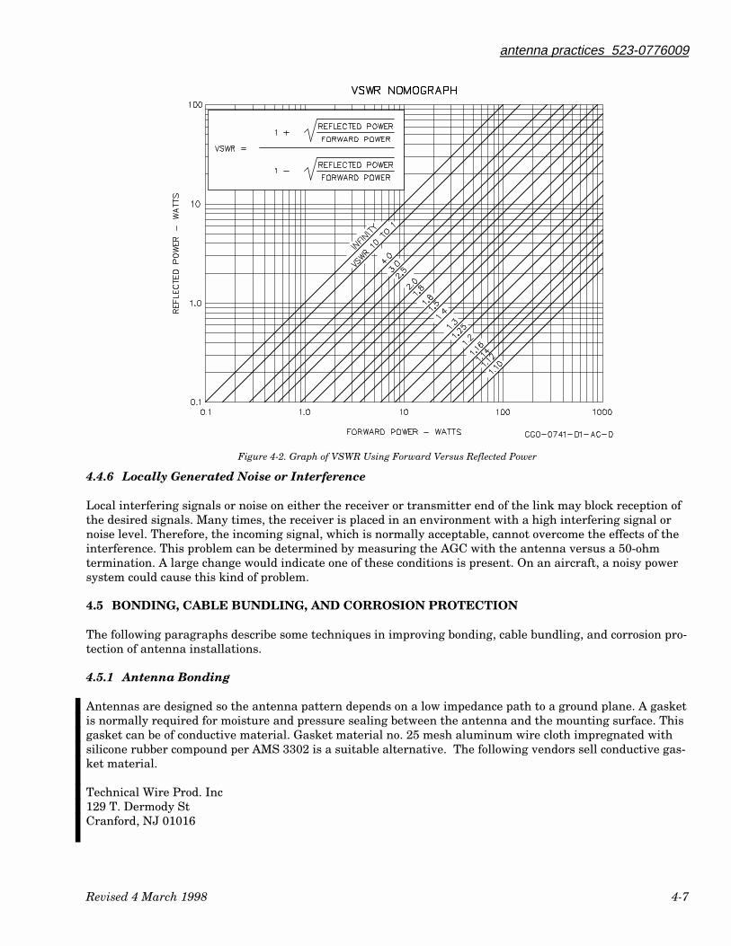
antenna practices 523-0776009
Revised 4 March 1998 4-7
Figure 4-2. Graph of VSWR Using Forward Versus Reflected Power
4.4.6 Locally Generated Noise or Interference
Local interfering signals or noise on either the receiver or transmitter end of the link may block reception ofthe desired signals. Many times, the receiver is placed in an environment with a high interfering signal ornoise level. Therefore, the incoming signal, which is normally acceptable, cannot overcome the effects of theinterference. This problem can be determined by measuring the AGC with the antenna versus a 50-ohmtermination. A large change would indicate one of these conditions is present. On an aircraft, a noisy powersystem could cause this kind of problem.
4.5 BONDING, CABLE BUNDLING, AND CORROSION PROTECTION
The following paragraphs describe some techniques in improving bonding, cable bundling, and corrosion pro-tection of antenna installations.
4.5.1 Antenna Bonding
Antennas are designed so the antenna pattern depends on a low impedance path to a ground plane. A gasketis normally required for moisture and pressure sealing between the antenna and the mounting surface. Thisgasket can be of conductive material. Gasket material no. 25 mesh aluminum wire cloth impregnated withsilicone rubber compound per AMS 3302 is a suitable alternative. The following vendors sell conductive gas-ket material.
Technical Wire Prod. Inc129 T. Dermody StCranford, NJ 01016
antenna practices 523-0776009
Revised 4 March 1998 4-8
Metex Electronics Corp.970 New Durham RdEdison, NJ 08817
The antenna ground plane is supplied from a conductive antenna gasket and/or through the antennamounting screws. If a conductive gasket is used, clean off all paint, grease, oil, lacquer, metal finisher, orother high resistance properties from an area slightly larger than the contact area. Ground, using the an-tenna mounting screws, is accomplished through the doubler plate installed to reinforce the aircraft surfaceskin. A bond between the aircraft skin and the doubler is required. Follow the bonding procedure listed inparagraph 2.1.1 when installing a doubler plate.
RF bonding or grounding requires a strap of metal instead of a wire. This strap must be bonded directly tothe airframe using silver- or tin-plated copper strap or aluminum strap or equivalent structure. The lengthto width ratio of the strap should not be more than 5 to 1 (that is, 127-mm (5-in) strap should be minimum of25.4 mm (1 in) wide).
Bonding to anodized or painted surfaces is not acceptable for good RF grounds. Surfaces to be bonded shouldbe sanded free of paint or anodic film and joined using screws with washers to ensure maximum surface con-tact over as large an area as possible. Materials should be carefully selected to avoid corrosion due to dis-similar metals. An electrically conductive substance should be used on all bare metal surfaces to retard cor-rosion. Refer to bonding paragraph 2.1 for additional information.
The antenna base should be well bonded to metal aircraft skin. Remove paint from around the mountingholes and use external-tooth lockwashers between the antenna base and the skin, or under the screw heads,to ensure a good connection between antenna and the skin. Inadequate bonding often results in poor rangeand in interference to other receivers. The skin should extend at least 24 inches from the base of the antennain every direction. Any less will probably reduce the usable communication distance at some bearings aroundthe aircraft.
4.5.1.1 RF Strap for Reducing RF Interference
RF bonding or grounding requires a strap of metal instead of a wire. This strap must be bonded directly tothe airframe using silver- or tin-plated copper strap or aluminum strap or equivalent structure. The lengthto width ratio of the strap should not be more than 5 to 1 (that is, 127-mm (5-in) strap should be minimum of25.4 mm (1 in) wide).
Bonding to anodized or painted surfaces is not acceptable for good RF grounds. Surfaces to be bonded shouldbe sanded free of paint or anodic film and joined using screws with washers to ensure maximum surface con-tact over as large an area as possible. Materials should be carefully selected to avoid corrosion due to dis-similar metals. An electrically conductive substance should be used on all bare metal surfaces to retard cor-rosion. Refer to bonding paragraph 2.1 for additional information.
4.5.1.2 Bonding on Composite, Fiberglass, or Fabric Skins
Aircraft with composite, fiberglass, or fabric skins require special antenna mounting techniques. In manycases, a metal doubler plate must be installed inside the skin to structurally support the antenna. The dou-bler plate should, then, extend at least 24 inches, in every direction, from the antenna base. If this is imprac-tical, it may be possible to cement metal foil inside the skin to extend the electrical ground plane to theminimum 24 inches. A foil extension must be well bonded to the doubler plate to be effective.
The antenna input cannot be protected against lightning voltages and currents without seriously degradingperformance. In composite aircraft, it may be necessary to connect the antenna to the transceiver structuresat both ends to help divert lightning currents away from the transceiver.
antenna practices 523-0776009
Revised 4 March 1998 4-9
4.5.2 Cable Bundling
Use the coax cable (or equivalent) recommended by the unit's manufacturer. Avoid sharp bends in the cable.Keep transmit cables away from receive cables if possible. Separate cables by routing transmit cables on oneside of the aircraft and receive cables on the other side.
4.5.3 Corrosion Protection
Connector corrosion is an easily prevented problem that is all too often encountered with antenna installa-tions. An excellent means of retarding, and in many cases eliminating, corrosion is a liberal application ofDow-Corning DC-4 silicon grease (Collins part number 005-0201-000) on both inside and outside of the an-tenna connector and its mate. DC-4 will not adversely affect performance in any way; its sole purpose here isto provide an effective barrier against moisture.
If RTV is used to seal connectors or antennas, a non-corrosive version of RTV, such as RTV-3415 is recom-mended. Some RTV's, such as RTV 732, contain Ascetic Acid. The Ascetic Acid causes connector contamina-tion and corrodes the connector. The RTV without Ascetic Acid does take longer to cure but the additionaltime more than makes up for a noncorroded connector.
4.6 ANTENNA SEALANT
Antenna installations require some sealant to supply a protection barrier from harmful elements. Follow theinstallation notes from the antenna manufacturer as to the sealing method recommended.
A connector seal kit is provided by Dorne and Margolin Inc. in kit #409. The compound supplied in thissealing kit is an easily applied room-temperature curing, tough, flexible silicone rubber encapsulant with anexceptional resistance to moisture, acids and alkalies, fuels, grease and oils (including Skydrol). The Dorneand Margolin, Inc. address is:
Dorne and Margolin, Inc.2950 Veterans Memorial HighwayBohemia, NY 11716Telephone: (516) 585-4000TWX: 510-228-6502
If the antenna is to be mounted on a pressurized fuselage, a leveling and sealing compound such as CoastProseal Aerodynamic Smoother may be needed. Proseal #890 (grey color) or #895 (aluminum color) may bepurchased from:
Aero Hardware1037 Boston Post Rd.Rye, New York 10580Telephone: (914) 967-8550Fax: (914) 967-8553
Coast Seal Distributors3795 Northwest 38th St.Miami, Florida 33142Telephone: (305) 888-6578
Wiles Associates1442 South Main St.Gardena, CaliforniaTelephone: (213) 538-4510
antenna practices 523-0776009
Revised 4 March 1998 4-10
4.7 ANTENNA SKIN MAPPING
Antenna skin mapping is the procedure of attempting to identify the location of least noise for a given an-tenna. Skin mapping is normally done on new equipment installations on a particular aircraft. Before skinmapping, contact the aircraft manufacturer to check if a previous installation may have already determinedthe ideal location for a particular antenna.
The basic principle of skin mapping is to try different antenna locations on the aircraft until the antenna lo-cation with the least interference is found. Anything electrical on the aircraft needs to be on, with the air-craft powered only by its engine alternators. All engines need to be running in order to simulate actual oper-ating conditions. Difficulties involved include: bonding the antenna to the aircraft at the different locations,locating the aircraft in a noise free area, running all the electronics on the aircraft, measuring the signal tonoise strength of each location, running the engines while conducting tests. These are some of the difficultiesto overcome in order to have reliable data. Consult your area field service engineer for additional informa-tion on skin mapping.

5.1 INTRODUCTION .................................................................................................................................................... 5-1
5.2 SWITCHING OF DATA........................................................................................................................................... 5-15.2.1 Compass Switching.........................................................................................................................................................5-15.2.2 Nav Switching .................................................................................................................................................................5-25.2.3 Attitude Switching..........................................................................................................................................................5-2
5.3 SPECIAL SWITCHING DEVICES......................................................................................................................... 5-2
5.4 ACCESSORY DEVICES.......................................................................................................................................... 5-3
5.5 VENDOR INFORMATION ..................................................................................................................................... 5-3
5.6 CONTROL WHEEL SWITCHES ............................................................................................................................ 5-4
5.7 DEBUGGING AND TROUBLESHOOTING.......................................................................................................... 5-45.7.1 Breaking Systems Into Subsystems...............................................................................................................................5-45.7.2 Troubleshooting Installations ........................................................................................................................................5-55.7.3 Troubleshooting Flow Charts.........................................................................................................................................5-55.7.4 Repeat Offenders ............................................................................................................................................................5-55.7.5 Synchro Troubleshooting................................................................................................................................................5-65.7.6 VOR Scalloping ...............................................................................................................................................................5-65.7.6.1 Signals in Space ...........................................................................................................................................................5-65.7.6.2 Aircraft-Caused Scalloping..........................................................................................................................................5-65.7.6.3 Scalloping fron Vertical Stabilizer Decals ..................................................................................................................5-7
5.8 INSTALLATION AND SETTING OF BRIDLE CABLES .................................................................................... 5-7
523-0776010-0031183rd Edition, 4 March 1998
Installation Practices Manual
NOTICE: This section replaces second edition dated 6 March 1992.
Special Installation Problems
Paragraph Page
Table of Contents
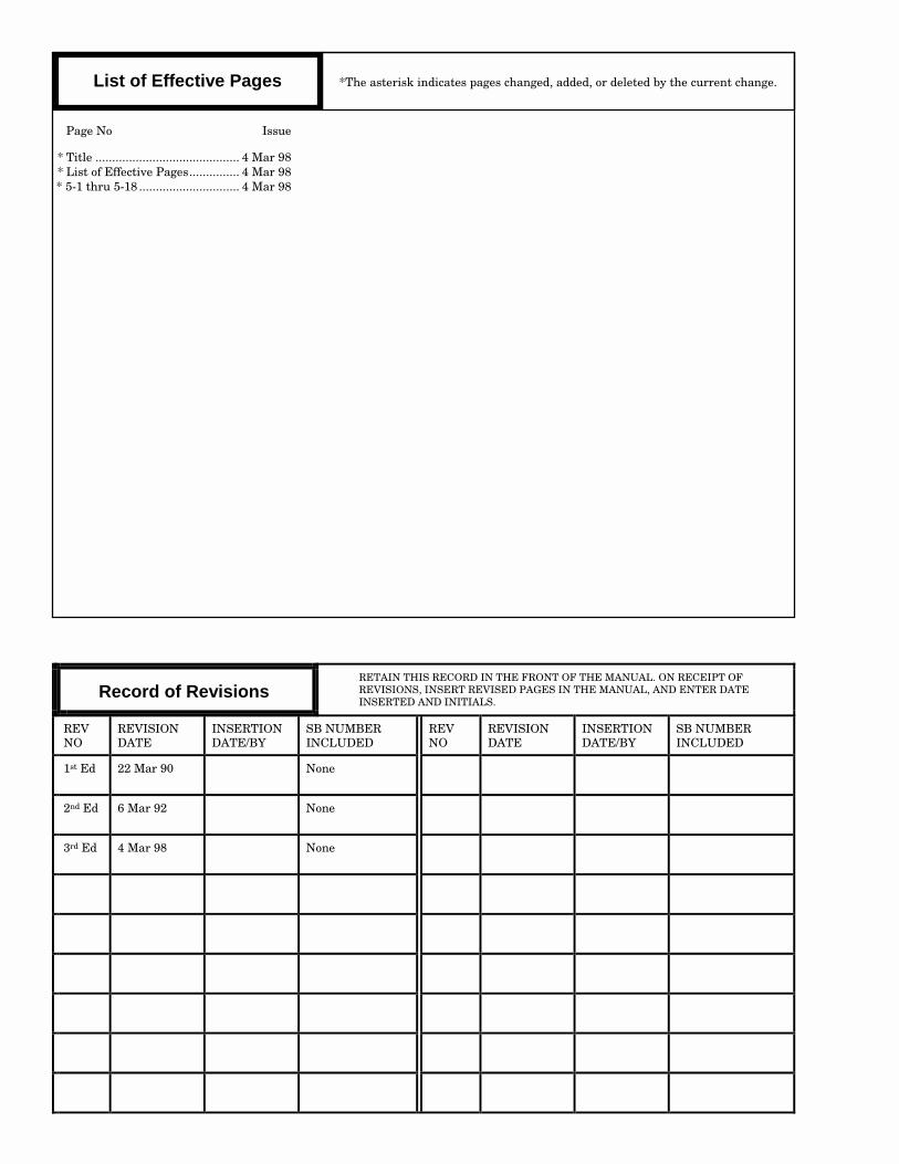
List of Effective Pages *The asterisk indicates pages changed, added, or deleted by the current change.
Page No Issue
* Title ........................................... 4 Mar 98* List of Effective Pages............... 4 Mar 98
* 5-1 thru 5-18 .............................. 4 Mar 98
Record of RevisionsRETAIN THIS RECORD IN THE FRONT OF THE MANUAL. ON RECEIPT OFREVISIONS, INSERT REVISED PAGES IN THE MANUAL, AND ENTER DATEINSERTED AND INITIALS.
REVNO
REVISIONDATE
INSERTIONDATE/BY
SB NUMBERINCLUDED
REVNO
REVISIONDATE
INSERTIONDATE/BY
SB NUMBERINCLUDED
1st Ed 22 Mar 90 None
2nd Ed 6 Mar 92 None
3rd Ed 4 Mar 98 None
section Vspecial installation
problems
Revised 4 March 1998 5-1
5.1 INTRODUCTION
The following paragraphs contain information on special or custom installation problems. Listed in theseparagraphs will be the devices to be used in custom installations.
Almost every custom avionics installation contains some special feature unique to the preference of theowner/operator. Occasionally an avionics manufacturer makes a recommendation regarding special tech-niques to use in an installation. These are usually optional.
Debugging and troubleshooting information is found in paragraph 5.7.
5.2 SWITCHING OF DATA
Custom installations usually require switching of data. Compass, nav, and attitude switching are the mostcommonly switched data. The following paragraphs describe some of the reasons for switching data and cau-tions to observe.
5.2.1 Compass Switching
In dual compass installation, compass data is commonly switched to provide the pilot or copilot with cross-side compass information. Normally this compass switching is a safeguard in the event of a failure of one ofthe compass systems. Some of the methods of connecting compass information to an HSI and RMI displayare as follows:
a. Both RMI and HSI display the same compass system. The RMI being the master and the HSI the re-peater, use the bootstrap output of the RMI.
b. Both RMI and HSI are directly connected from the same compass source.c. The HSI is the master with the RMI the repeater, from the HSI bootstrap output.d. The HSI displays the #1 compass, the RMI repeater displays the #2 compass.
Method 'd' is normally what is used. The pilot's HSI displays #1 compass data, the pilot's RMI displays #2compass data, the copilot's HSI displays #2 compass data, and the copilot's RMI displays #1 compass data.This gives the pilot a quick reference to either compass in case of a system failure. With compass informa-tion from both compasses displayed on the pilot's or copilot's panel, compass switching is not needed. In anyof the cases listed, proper documentation and annunciation is required.
Switching of compass information, if desired, must be done with an isolated source so as not to endanger theloss of switching a good system into a defective indicator and possibly losing the second system.
Another common installation practice is to isolate the compass information source that feeds the VOR re-ceivers. The switching of the RMI pointer would cause the compass card to oscillate.
special installation problems 523-0776010
Revised 4 March 1998 5-2
Compass outputs have limited capacity to drive indicators. A bootstrap output may be needed to drive an-other indicator compass card. Consult the compass installation manual on the output capabilities of thecompass(es) installed.
5.2.2 Nav Switching
INS, VOR, VLF, OMEGA, and RNAV can be displayed on the HSI indicator. This is accomplished by dataswitching.
If EFIS is used, the nav switching is accomplished with the EFIS processor. This has made nav switchingmuch easier. The EHSI also displays the source of nav data it is using. Selection of which nav to be used iscontrolled by the EFIS system.
If a mechanical HSI is used, the task of switching nav information is accomplished through external relaysand switches. The installation of the various navigation systems to the HSI must be annunciated and inter-locked to assure the pilot that the display is viewing what was selected. It is essential that the displayeddata be annunciated as to the source of the data. Example: if the VLF is the nav source, then an annuncia-tor near the HSI displays VLF as the source.
When more than one relay is used for the switching of the data, the data annunciator or data selector inter-lock must daisy chain through all the relays. This ensures that all the relays did activate to provide theproper display.
When switching data to the HSI, interlock the autopilot modes so the NAV mode will automatically clear andthe autopilot reverts to the turn knob mode. This prevents unwarranted or unusual commands to theautopilot.
In some installations, the pilot may request that the autopilot be on one nav system and the pilot monitoringof the navigation progress on another system. The navigation data connected to the autopilot must be moni-tored and, in case of failure, an annunciator be illuminated to the failure or the loss of steering informationto the autopilot.
Data switching takes many relays and relays do fail. Design the switching in such a manner that when arelay does fail, the system left operational is VOR/LOC.
5.2.3 Attitude Switching
Attitude switching is also accomplished with relays in non-EFIS installations. If dual vertical gyros areused, isolation between the two gyros should be maintained. Refer to the vertical gyro's installation manualfor the output specification. The attitude switching must be interlocked with the autopilot system. Thisprovides the same attitude information to pilot and the autopilot. Design the switching so that in the re-laxed position, the attitude system is in the normal position.. This way, if a relay failure occurs, normal atti-tude information will be displayed.
5.3 SPECIAL SWITCHING DEVICES
Some special features that may be customer requested are: instrumentation/display switching, navigationcontrol switching, and autopilot control switching. Recommended options may be out-of-view biasing speciallogic and self-test interlocks.
There are several devices that may be used in switching; each device has benefits and limitations. Some ofthe devices are:
special installation problems 523-0776010
Revised 4 March 1998 5-3
SwitchesRelaysLedex switchesSolid-state switches
a. Switches - usually these are used for direct switching or remote control of another switching device suchas a remote relay. The switches are normally located in the cockpit and limited by size.
b. Relays - the most common switching device. Usually hermetically sealed relays are used because of theirquality and ability to switch dry (low or zero voltage) circuits. These devices are always remotely con-trolled. They are usually limited to double throw. This limitation usually means that a large number ofrelays are required to do a simple switching operation.
c. Ledex switches - are basically relays that are motorized. This feature allows for the common to havemore than two controls, in most cases five. The benefits of this are obvious. The limitation comes whenmore than one Ledex is required for a switching operation. If one of the devices fail, the unswitched datawould create confusion in the cockpit. Because of this, elaborate interlocks and sequence logic must beemployed to ensure that all the devices are working in unison. Ledex switches also are useful whenswitching a large number of lines such as nav transfer information from one side to the other.
d. Solid-state - is simply the use of semiconductor switching. Normally this type of switching is used forlogic switching or remote control, in most cases where current is low.
5.4 ACCESSORY DEVICES
All switching should be kept as simple as possible in the cockpit, regardless of how complex the operation.Although switching is explained in the Flight Manual Supplement, it should be clearly labeled and annunci-ated enough to require little or no explanation.
All switching should be annunciated to reflect the actual condition of the switching devices. Failure of one ormore parts of the switching should cause the switched equipment to revert back to a normal configuration.
Another point to consider is system integrity. When switching a system or systems all things must be con-sidered such as, instrumentation, annunciation, phasing, grounding, system differences, shielding continu-ity, induced RFI and/or EMI.
Aircraft manufacturers normally install an accessory box which contains switching relays, diode isolators,and other assorted accessories. Consult the aircraft manufacturer for information on the accessory box. In-stall accessory items in a box such as a "Bud utility box".
5.5 VENDOR INFORMATION
There are a large variety of vendors for switches, relays, and other accessory items. Quality is the most im-portant aspect to be considered in selecting a component. The integrity of the installation depends on eachpiece of equipment performing its designed task. Some of the vendors which sell relays, switches, electron-ics, and boxes are the following:
Newark Electronics500 North Pulaski RoadChicago, IL 60624Telephone: (312) 784-5100Facsimile: (312) 638-7652
Ledex Inc.801 Scholz DriveVandalia, OH 45377
special installation problems 523-0776010
Revised 4 March 1998 5-4
Telephone: (513) 898-3621Facsimile: (513) 898-8624
Bud Industries Inc. (boxes)4605 E. 355th St.Willowghby, OH 44094-0431Telephone: (216) 946-3200Facsimile: (216) 951-4015
Leach Corporation (relays)5915 Avalon Blvd.Los Angeles, CA 90003Telephone: (213) 232-8221Facsimile: (213) 234-6461
C & K Components, Inc. (Switches)15 Riverdale Ave.Newton, MA 02158-1082Telephone: (617) 964-6400Telex: 92-2544
Master Distributors (relays, switches)101 Olympic Blvd.Santa Monica, CA 90404Telephone: (213) 452-1229
5.6 CONTROL WHEEL SWITCHES
The location and layout of these switches must be where the pilot can operate the switch without handmovement. Control wheel switches are normally located on the left side of the pilot's control wheel and onthe right side of the copilot's wheel.
Some of the control wheel switches are as follows: electric trim, trim disengage, pitch sync, go- around,autopilot disengage, interphone, transponder ident, transmit, control wheel steering, and nose wheel steer-ing control. The switches used are dependent on the installation and customer preferences. With very lim-ited space, the most important and most used switches should be installed in the easiest to reach locations.Install the less important switches where it takes a little more effort to reach. Identify all switches clearly.Keep the switch count to a minimum.
Switches that are for emergency disconnects, etc., AP disengage, must be red in color.
5.7 DEBUGGING AND TROUBLESHOOTING
The following paragraphs contain information on debugging and troubleshooting an installation. The theoryof debugging a system is to break the system down into subsystems. Then troubleshoot the subsystem untilthe problem is found.
5.7.1 Breaking Systems Into Subsystems
Take one problem at a time and follow it through to its subsystems. Find out how the systems are suppose towork. In today’s “custom” installations, knowledge is needed as to how the system was intended to operate.Try to keep things as simple as possible. Sometimes finding what works can help narrow down what doesn’twork. Below is a systematic approach to troubleshooting an installation.
special installation problems 523-0776010
Revised 4 March 1998 5-5
a. List all the systems involves in the problem.b. Break the systems into subsystems.c. Find or make a block diagram of the units involved in the subsystems involved.d. Trace the problem back through the subsystem blocks.e. Try to eliminate half the blocks involved at the time by checking for the problem in the middle of the
problem path.f. Continue to divide the remaining blocks in half until the problem block is found.g. If possible, substitute or swap the unit involved to eliminate either the wiring or the unit.
A systematic approach may seem longer, but over a period of time will save many troubleshooting hours.Problems can lead you in circles, and the systematic approach helps eliminate the circles. On new installa-tions, a common problem found is swapped wires or faulty connections. If a breakout box is available, trackthe path of the problem to find out where the problem is or is not located.
5.7.2 Troubleshooting Installations
Troubleshooting is a process of narrowing the alternatives until the problem area is found. If possible, try tonarrow the number of alternatives in half, then narrow in half again, continuing until the problem is found.
When troubleshooting an aircraft system with multiple problems, start with the simplest subsystem. Prog-ress from the simplest subsystem to the most complex. Normally the problems are related. Solving a simpleproblem may also solve a complex problem.
If unsure what to do next, sometimes a telephone call to a manufacturer’s representative or field service en-gineer can really help. Ask for assistance if you get stuck on a problem. Sometimes a different perspectivewill trigger an idea of what to do next.
5.7.3 Troubleshooting Flow Charts
Figures 5-1 through 5-5 are flow charts for Collins Comm/Nav/Pulse equipment. These flow charts are de-signed to aid in finding the line replaceable unit to send in for checkout/repair.
The main purpose of the flow charts is flight-line maintenance. They may also be useful in installation trou-bleshooting.
5.7.4 Repeat Offenders
Upon completion of the aircraft avionics installation, a log of equipment should be made. This log should in-clude information on each unit installed. The purpose of the log is to keep an accurate record of maintenanceon each nit. If set up properly, an accurate account of maintenance on each unit helps eliminate “repeat of-fenders”.
A repeat offender is a radio which continues to be removed for repair only to be returned with a “no problemfound” report. The problem may be related to the unit removed and not the unit itself. If the informationthat this unit was removed for an identical problem earlier is included, further investigation will occur muchsooner. This would save countless repair hours and bills. It has been proven that repeat offenders have costcountless amounts in unnecessary repair bills. An accurate account will allow a problem to be narroweddown. The customer will greatly appreciate an easy to maintain log in an effort to reduce repeat offenders.
It is important to identify chronic problems in airplanes in an efficient manner. The more information avail-able to the technician as to the history of the aircraft, the more easily chronic (repeat) problems can besolved.
special installation problems 523-0776010
Revised 4 March 1998 5-6
5.7.5 Synchro Troubleshooting
Nav synchro systems require some basic information on the synchro systems in order to troubleshoot. Thestandard synchro has 26 V ac applied to the H and C input rotor. The X, Y, and Z output stators provide thereturn position information to the nav. The stator information is processed by the nav and the left/rightneedle and TO/FROM flag output from the nav to the indicator.
The following may be useful in troubleshooting synchro installation problems. Table 5-1 is a listing of com-parison voltages at certain angles. The data connections are between stator windings and stator and rotorwindings. If viewed on a dual trace oscilloscope, external triggered by the 26 V ac, at 0 degree the signal atstator X will be equal in amplitude and phase to the signal at stator Y. The phase at 0 degree at stator X andY will be 180 degrees out-of-phase with the 26-V ac reference.
A breakout box is an important aspect in troubleshooting a synchro system. It is difficult to check the sys-tem without all the units connected. All units in the synchro system have to be connected in order to trou-bleshoot the system.
Consult the manufacturer’s installation manuals for additional information on interconnecting synchros.Read all notes on the installation diagram.
5.7.6 VOR Scalloping
VOR scalloping is a problem that has been around as long as VOR itself. There are many causes for VORscalloping. The following paragraphs list some of the most common causes and suggestions for reducingVOR scalloping.
5.7.6.1 Signals in Space
Standard VOR stations, reflecting from hills, buildings, trees, etc., add vectorially to the desired, direct sig-nal from the station. If the receiver were stationary, this would produce a constant error. Where the re-ceiver moves, it tends to pass from errors in one direction to those in the other with varying magnitudes inan erratic manner. The result is course roughness or scalloping.
Newer navigation receivers, such as the VIR-32 or VIR-432, incorporate a digital computer to compute theVOR bearing and filter the signal. Its filter is more complex than was possible in analog instrumentationcircuits, so it does a much better job of eliminating wiggle without introducing unacceptable lag.
Older analog receivers filter the current which moves the needle. The lag due to filtering not only gets in theway of navigation, it also makes it more difficult for a pilot to center the needle with the OBS knob, check hisbearing, or fly direct from present position to the station.
5.7.6.2 Aircraft-Caused Scalloping
The entire aircraft is part of the antenna system. Radio frequency currents flow in the skin when any signalis being received (or transmitted). Any change in the electrical characteristics of the skin changes the waycurrent is distributed. If the shin RF characteristics change erratically in flight, the result is unwantedmodulation noise on the VOR signal (and any other signals such as ILS, comm, etc.). These erratic changescould be caused by inadequate bonding between skin panels, causing the resistance to change under flexingand vibration. They could be caused by control surfaces not adequately bonded to the rest of the airframe(currents flow in ailerons, flaps, rudder, elevator, spoilers, and trim tabs as they do in other metal skin pan-els). It is even possible
If noise caused by poor skin bonding has components near the 30-Hz VOR bearing-signal frequency , the de-viation needle will tend to move erratically. Improved bonding will help reduce this VOR scalloping.
BUSINESS AND REGIONAL SYSTEMSINSTALLATION PRACTICES MANUAL
Temporary Revision 1523-0775254-01311A May 26/00
Installation Practices Manual
INSTALLATION MANUAL (523-0775254, 3RD EDITION, DATED MAR 4/98)
TEMPORARY REVISION NO. 01Insert facing page 5-7.
Subject: Change to Advisory Circular AC 43.13-1A.
Advisory Circular AC 43.13-1A has been revised and is now labeled AC 43.13-1B, dated 9/8/98.The following paragraphs will be reworded as follows:
5.8.a. Inspect bridle cables in accordance with FAA document AC-43.13-1B to be sure they arein serviceable condition.
5.8.e.2. Remove the lubricant and corrosion protection from the primary aircraft cable where thecable clamp will be located in accordance with AC-43.13-1B.
Page 4
special installation problems 523-0776010
Revised 4 March 1998 5-7
Static discharge is another possible source of noise which could have components around the bearing-signalfrequency. Static wicks must be installed properly and maintained in good condition. Most types occasion-ally break off due to flutter and vibration. Replace broken static wicks immediately to avoid degraded radioperformance.
Propeller-driven airplanes and helicopters have another scallop generator, the prop or rotor. Typical air-plane propellers are about one-half the wavelength long of VOR frequencies, so they may be good rotatingparasitic antenna elements. Helicopter rotors are so large, they directly affect the sensitivity of the antennasas they pass near. In either case, the rotating element may produce unwanted modulation on the navigationsignal, if this undesired signal possesses components to which the instrumentation circuits are sensitive inairplanes. ILS perturbations are more common than VOR scalloping, because the propeller chops or reflectsthe signal at a rate usually greater than 30 Hz. In helicopters, the rotor chop frequency has harmonics nearboth VOR and ILS information frequencies.
Propeller or rotor modulation can be particularly troublesome because they may exist at a very stable fre-quency. In this case, it produces a steady error, rather than scalloping. Currently, no way has been found tosort out on-frequency interfering signals without introducing even worse effects into the receivers. Eventhose a little off-frequency, which produce the windshield-wiper needle action, are subject to the same limita-tions as noise die to signal discharge. Limitations on allowable lag make it impossible to eliminate the noiseeffect totally.
5.7.6.3 Scalloping from Vertical Stabilizer Decals
An investigation of a VOR system with decals located within 2 or 3 feet of the VOR antennas has revealedthe decals can cause “scalloping” of the instrument readings due to static electricity buildup on the surface ofthe decal. It is recommended that decals (flags, logos, etc.) be removed and the design painted on the surfaceto prevent “scalloping”.
5.8 INSTALLATION AND SETTING OF BRIDLE CABLES
The following procedure assumes that the aircraft manufacturer’s approved maintenance manual or STCholder’s installation data is available, and that cable tensions, slip clutch settings, and other critical informa-tion is included.
a. Inspect bridle cables in accordance with FAA document AC-43.13-1A, chapter 4 to be sure they are inserviceable condition.
b. Verify the capstan slip clutch has been set in accordance with approved data.c. Install and safety wire the bridle cables onto the capstan drum, properly wrap the cables onto the drum,
and install the cable guard at the proper orientation.d. Verify the primary aircraft cables are properly set.e. Mount the capstan in the aircraft, then route and secure the bridle cables to the control attach points in
accordance with installation instructions.If the bridle cables are attached to the primary aircraft cables with cable clamps, then:1. Extend the bridle cable turnbuckle to its maximum extension and loosely install the cable clamps,
being careful that the cables are routed properly in the cable clamp grooves.2. Remove the lubricant and corrosion protection from the primary aircraft cable where the cable clamp
will be located in accordance with AC-43.13-1A, chapter 4, paragraph 198.2.C.3. Position the cable clamps in accordance with the installation instructions. Tighten one cable clamp
in position, slide the other clamp by hand to tighten the bridle cable, and tighten in position.4. Apply Inspectors Lacquer (Torque Paint) to the junction of the cable and the aircraft cable opposite
the servo, so that any slippage can be detectedf. Adjust the bridle cable tension to approximately maximum value, engage the autopilot, and run the air-
craft controls from stop to stop several times (overpowering the servo) to seat the bridle cables in thecapstan drum droves and other points of contact.

special installation problems 523-0776010
Revised 4 March 1998 5-8
An alternate means to seat the cables is to apply alternating lateral pressure by hand to the bridle cables(being careful not to apply too much force) with the controls moved to opposite stops.
g. Readjust the cable tension to the nominal value listed in the installation data, and repeat step f. If thecable tension remains nominal, safety wire the tensioning device and cable clamp bolts and go to step h.If not, repeat step f until it does.
Note
Care must be taken when using a cable tensiometer that the cable being tested isplaced in the middle of the tool’s working surfaces, the tool is set gently, the tool isadjusted to the proper size cable, and that no external loads are applied by the tool.
h. Operate the aircraft controls and, if practical, the autopilot controls through their full range of travelwhile checking for any binding, interference or misalignment.
i. Re-check the installation to be sure that all safety devices are secure and able guards, fairleads, andkeepers are in the proper position and not rubbing on any moving parts. Survey the area for misplacedtools, hardware, or any other foreign items and secure the area.
j. Recheck the cable tensions after the first few hours of operation.
Table 5-1. Synchro Data Referenced to 26 V AC.
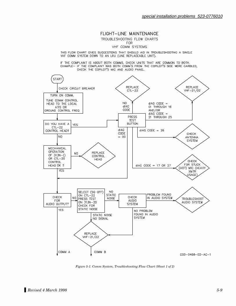
special installation problems 523-0776010
Revised 4 March 1998 5-9
Figure 5-1. Comm System, Troubleshooting Flow Chart (Sheet 1 of 2)
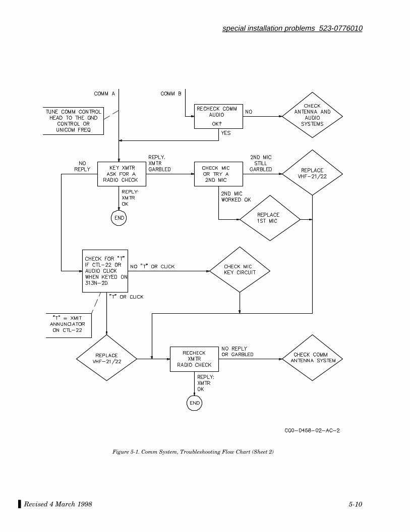
Revised 4 March 1998
special installation problems 523-0776010
5-10
Figure 5-1. Comm System, Troubleshooting Flow Chart (Sheet 2)

special installation problems 523-0776010
Revised 4 March 1998 5-11
Figure 5-2. Nav System, Troubleshooting Flow Chart (Sheet 1 of 5)
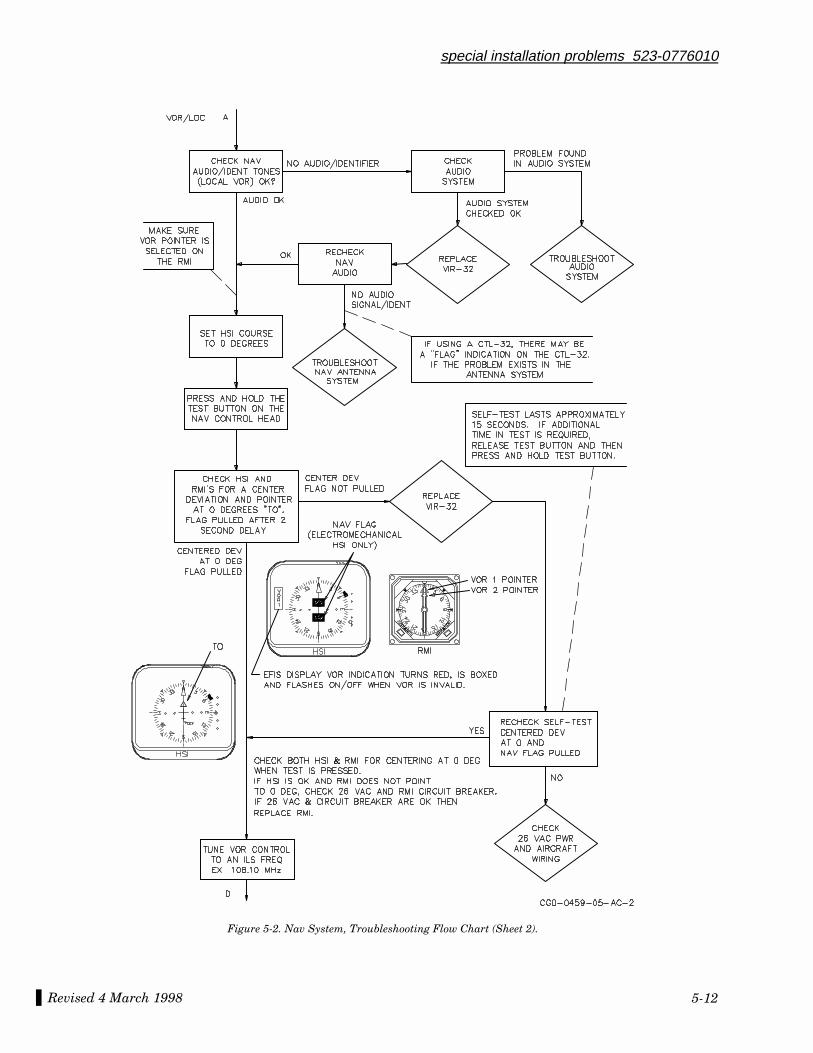
Revised 4 March 1998
special installation problems 523-0776010
5-12
Figure 5-2. Nav System, Troubleshooting Flow Chart (Sheet 2).
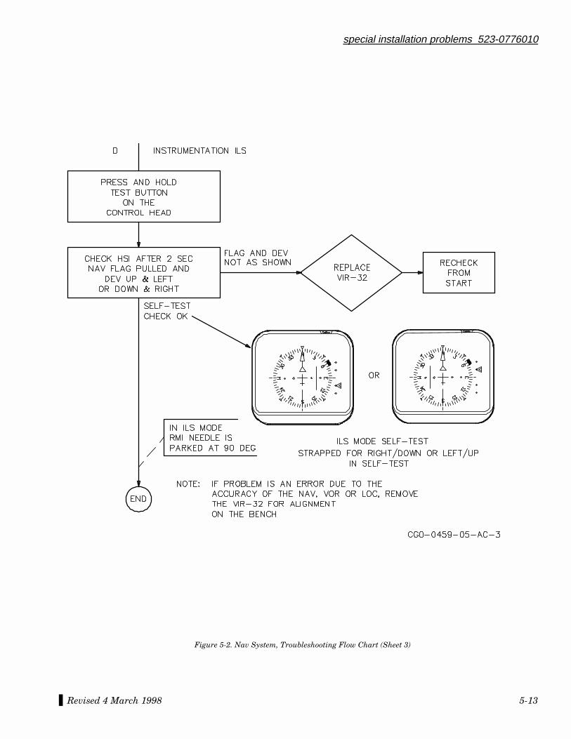
special installation problems 523-0776010
Revised 4 March 1998 5-13
Figure 5-2. Nav System, Troubleshooting Flow Chart (Sheet 3)
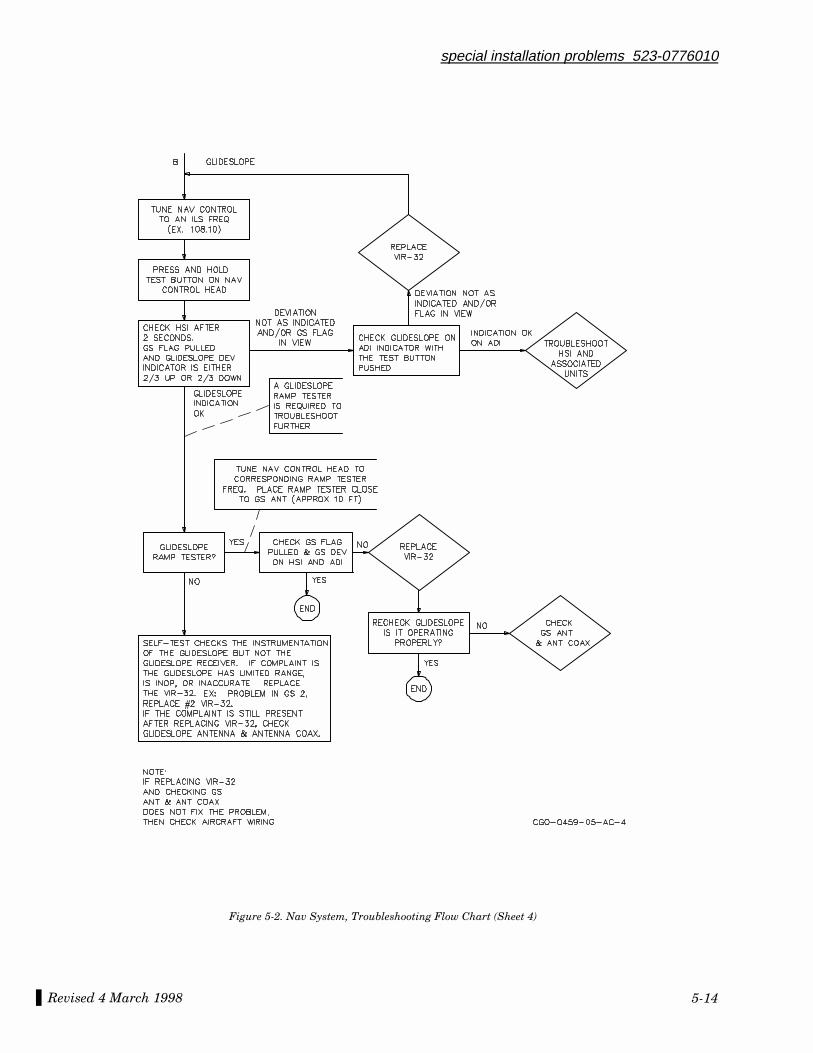
Revised 4 March 1998
special installation problems 523-0776010
5-14
Figure 5-2. Nav System, Troubleshooting Flow Chart (Sheet 4)
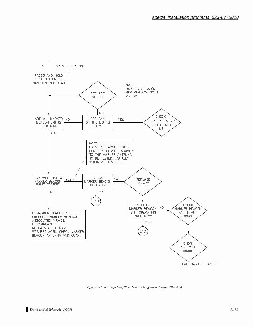
special installation problems 523-0776010
Revised 4 March 1998 5-15
Figure 5-2. Nav System, Troubleshooting Flow Chart (Sheet 5)
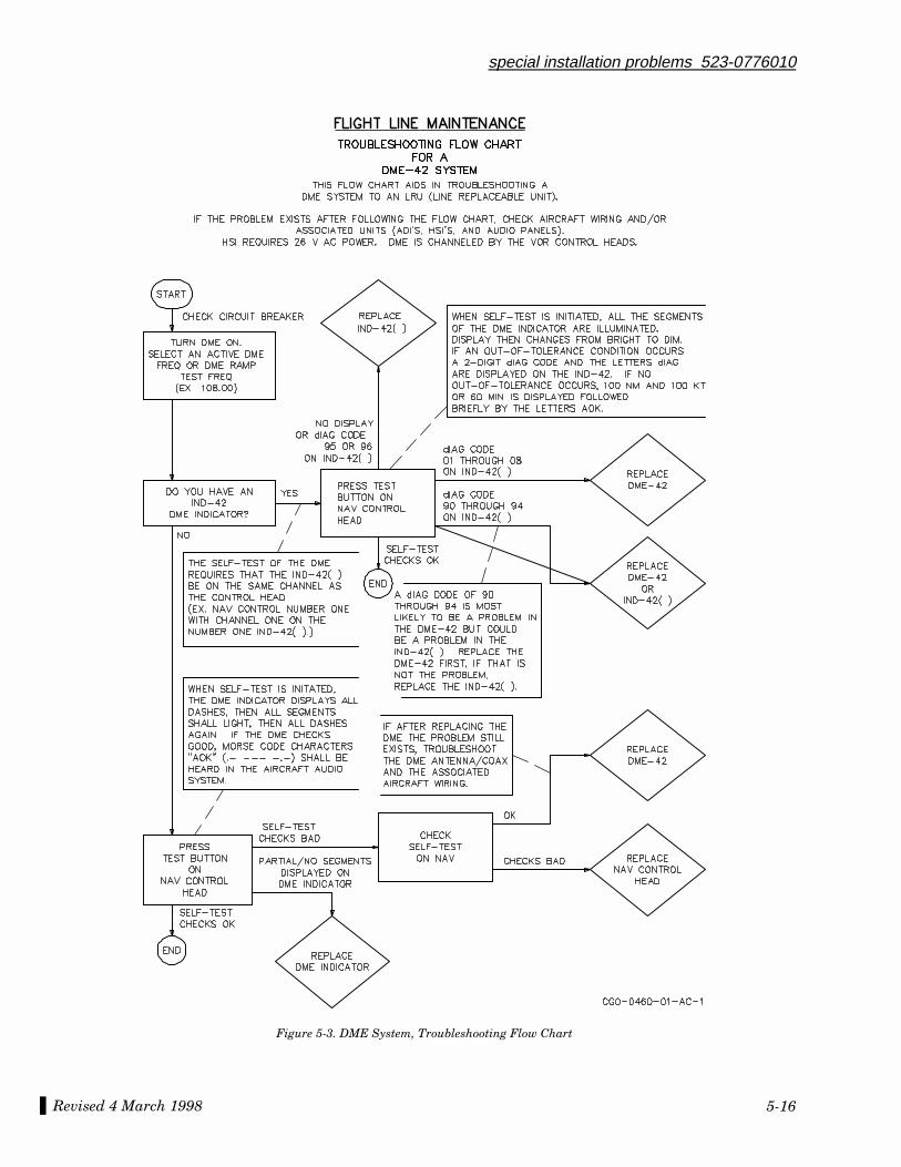
Revised 4 March 1998
special installation problems 523-0776010
5-16
Figure 5-3. DME System, Troubleshooting Flow Chart
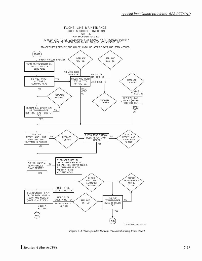
special installation problems 523-0776010
Revised 4 March 1998 5-17
Figure 5-4. Transponder System, Troubleshooting Flow Chart
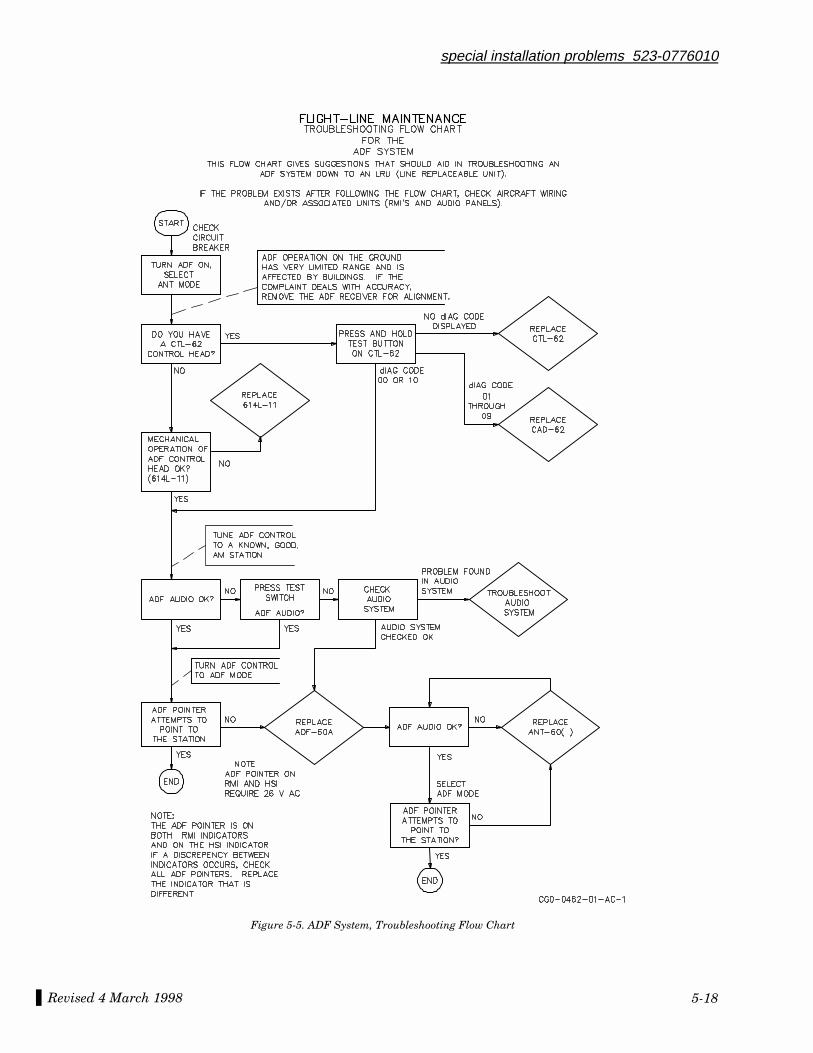
Revised 4 March 1998
special installation problems 523-0776010
5-18
Figure 5-5. ADF System, Troubleshooting Flow Chart

A.1 INTRODUCTION....................................................................................................................................................A-1
A.2 GENERAL FLIGHT-LINE SCHEDULED MAINTENANCE INFORMATION..................................................A-2
A.2.1 Weather Radar Antenna...............................................................................................................................................A-2A.2.2 AP Servo/Mount.............................................................................................................................................................A-2A.2.3 Air Data Computer........................................................................................................................................................A-2A.2.4 VHF Navigation Receiver .............................................................................................................................................A-2A.2.5 Transponder ..................................................................................................................................................................A-3A.2.6 Routine CRT Cleaning (EFIS) ......................................................................................................................................A-3A.2.7 Cleaning of Cockpit Equipment....................................................................................................................................A-3A.2.7.1 Cleaning Control Panels and Instrument Bezels .....................................................................................................A-3A.2.7.2 Cleaning CRT and Plastic Display Faces..................................................................................................................A-3
A.3 MISCELLANEOUS INFORMATION ....................................................................................................................A-4
A.3.1 dBm to Microvolt Correlation Chart ............................................................................................................................A-4A.3.2 dBW to Watt Correlation Chart ...................................................................................................................................A-4
523-0776031-0031183rd Edition, 4 March 1998
Installatio n Practice s Manual
NOTICE: This section replaces second edition dated 6 March 1992.
Appendix A
Paragraph Page
Table of Contents

List of Effective Pages *The asterisk indicates pages changed, added, or deleted by the current change.
Page No Issue
* Title ........................................... 4 Mar 98* List of Effective Pages............... 4 Mar 98
*A-1 thru A-96.............................. 4 Mar 98
Record of RevisionsRETAIN THIS RECORD IN THE FRONT OF THE MANUAL. ON RECEIPT OFREVISIONS, INSERT REVISED PAGES IN THE MANUAL, AND ENTER DATEINSERTED AND INITIALS.
REVNO
REVISIONDATE
INSERTIONDATE/BY
SB NUMBERINCLUDED
REVNO
REVISIONDATE
INSERTIONDATE/BY
SB NUMBERINCLUDED
1st Ed 22 Mar 90 None
2nd Ed 6 Mar 92 None
3rd Ed 4 Mar 98 None
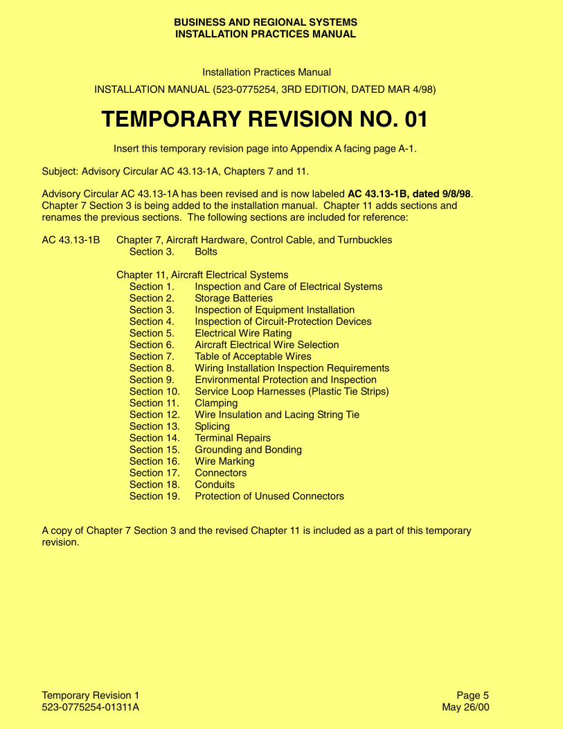
BUSINESS AND REGIONAL SYSTEMSINSTALLATION PRACTICES MANUAL
Temporary Revision 1523-0775254-01311A May 26/00
Installation Practices Manual
INSTALLATION MANUAL (523-0775254, 3RD EDITION, DATED MAR 4/98)
TEMPORARY REVISION NO. 01Insert this temporary revision page into Appendix A facing page A-1.
Subject: Advisory Circular AC 43.13-1A, Chapters 7 and 11.
Advisory Circular AC 43.13-1A has been revised and is now labeled AC 43.13-1B, dated 9/8/98.Chapter 7 Section 3 is being added to the installation manual. Chapter 11 adds sections andrenames the previous sections. The following sections are included for reference:
AC 43.13-1B Chapter 7, Aircraft Hardware, Control Cable, and TurnbucklesSection 3. Bolts
Chapter 11, Aircraft Electrical SystemsSection 1. Inspection and Care of Electrical SystemsSection 2. Storage BatteriesSection 3. Inspection of Equipment InstallationSection 4. Inspection of Circuit-Protection DevicesSection 5. Electrical Wire RatingSection 6. Aircraft Electrical Wire SelectionSection 7. Table of Acceptable WiresSection 8. Wiring Installation Inspection RequirementsSection 9. Environmental Protection and InspectionSection 10. Service Loop Harnesses (Plastic Tie Strips)Section 11. ClampingSection 12. Wire Insulation and Lacing String TieSection 13. SplicingSection 14. Terminal RepairsSection 15. Grounding and BondingSection 16. Wire MarkingSection 17. ConnectorsSection 18. ConduitsSection 19. Protection of Unused Connectors
A copy of Chapter 7 Section 3 and the revised Chapter 11 is included as a part of this temporaryrevision.
Page 5
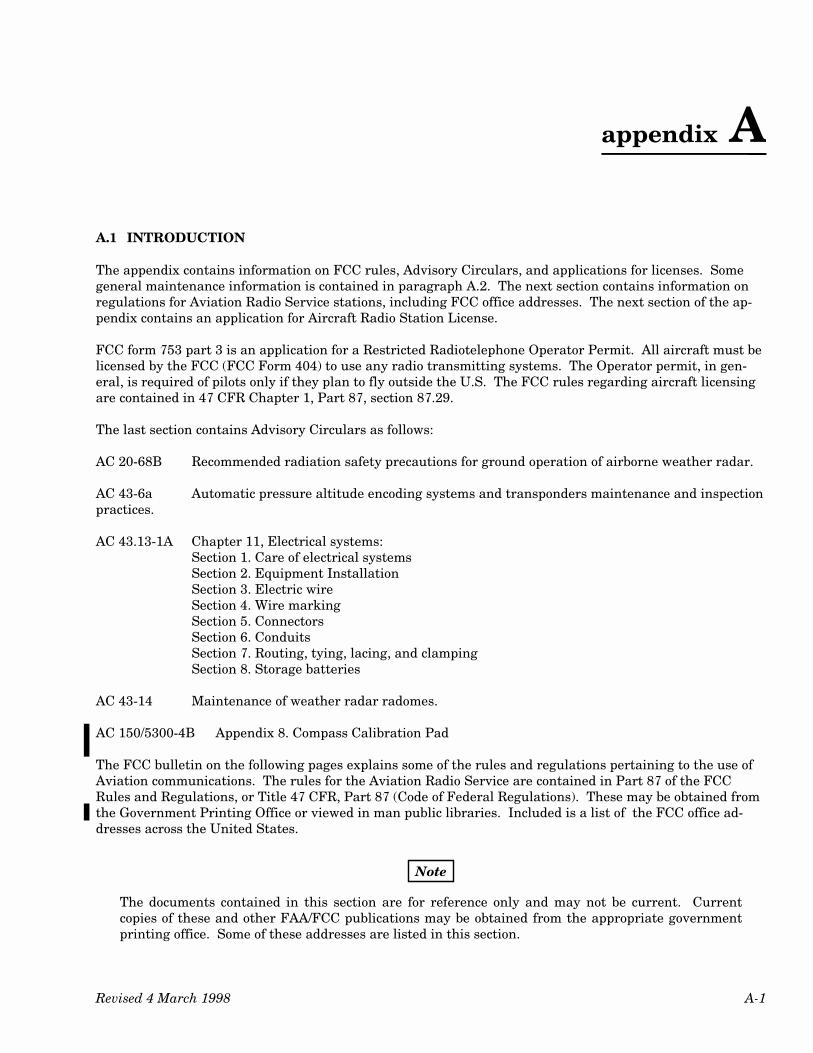
appendix A
Revised 4 March 1998 A-1
A.1 INTRODUCTION
The appendix contains information on FCC rules, Advisory Circulars, and applications for licenses. Somegeneral maintenance information is contained in paragraph A.2. The next section contains information onregulations for Aviation Radio Service stations, including FCC office addresses. The next section of the ap-pendix contains an application for Aircraft Radio Station License.
FCC form 753 part 3 is an application for a Restricted Radiotelephone Operator Permit. All aircraft must belicensed by the FCC (FCC Form 404) to use any radio transmitting systems. The Operator permit, in gen-eral, is required of pilots only if they plan to fly outside the U.S. The FCC rules regarding aircraft licensingare contained in 47 CFR Chapter 1, Part 87, section 87.29.
The last section contains Advisory Circulars as follows:
AC 20-68B Recommended radiation safety precautions for ground operation of airborne weather radar.
AC 43-6a Automatic pressure altitude encoding systems and transponders maintenance and inspectionpractices.
AC 43.13-1A Chapter 11, Electrical systems:Section 1. Care of electrical systemsSection 2. Equipment InstallationSection 3. Electric wireSection 4. Wire markingSection 5. ConnectorsSection 6. ConduitsSection 7. Routing, tying, lacing, and clampingSection 8. Storage batteries
AC 43-14 Maintenance of weather radar radomes.
AC 150/5300-4B Appendix 8. Compass Calibration Pad
The FCC bulletin on the following pages explains some of the rules and regulations pertaining to the use ofAviation communications. The rules for the Aviation Radio Service are contained in Part 87 of the FCCRules and Regulations, or Title 47 CFR, Part 87 (Code of Federal Regulations). These may be obtained fromthe Government Printing Office or viewed in man public libraries. Included is a list of the FCC office ad-dresses across the United States.
Note
The documents contained in this section are for reference only and may not be current. Currentcopies of these and other FAA/FCC publications may be obtained from the appropriate governmentprinting office. Some of these addresses are listed in this section.
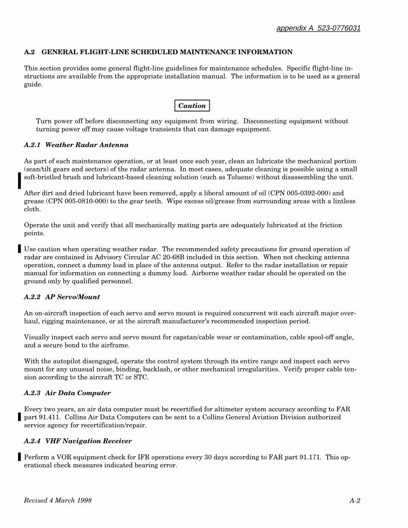
Revised 4 March 1998
appendix A 523-0776031
A-2
A.2 GENERAL FLIGHT-LINE SCHEDULED MAINTENANCE INFORMATION
This section provides some general flight-line guidelines for maintenance schedules. Specific flight-line in-structions are available from the appropriate installation manual. The information is to be used as a generalguide.
Caution
Turn power off before disconnecting any equipment from wiring. Disconnecting equipment withoutturning power off may cause voltage transients that can damage equipment.
A.2.1 Weather Radar Antenna
As part of each maintenance operation, or at least once each year, clean an lubricate the mechanical portion(scan/tilt gears and sectors) of the radar antenna. In most cases, adequate cleaning is possible using a smallsoft-bristled brush and lubricant-based cleaning solution (such as Toluene) without disassembling the unit.
After dirt and dried lubricant have been removed, apply a liberal amount of oil (CPN 005-0392-000) andgrease (CPN 005-0810-000) to the gear teeth. Wipe excess oil/grease from surrounding areas with a lintlesscloth.
Operate the unit and verify that all mechanically mating parts are adequately lubricated at the frictionpoints.
Use caution when operating weather radar. The recommended safety precautions for ground operation ofradar are contained in Advisory Circular AC 20-68B included in this section. When not checking antennaoperation, connect a dummy load in place of the antenna output. Refer to the radar installation or repairmanual for information on connecting a dummy load. Airborne weather radar should be operated on theground only by qualified personnel.
A.2.2 AP Servo/Mount
An on-aircraft inspection of each servo and servo mount is required concurrent wit each aircraft major over-haul, rigging maintenance, or at the aircraft manufacturer’s recommended inspection period.
Visually inspect each servo and servo mount for capstan/cable wear or contamination, cable spool-off angle,and a secure bond to the airframe.
With the autopilot disengaged, operate the control system through its entire range and inspect each servomount for any unusual noise, binding, backlash, or other mechanical irregularities. Verify proper cable ten-sion according to the aircraft TC or STC.
A.2.3 Air Data Computer
Every two years, an air data computer must be recertified for altimeter system accuracy according to FARpart 91.411. Collins Air Data Computers can be sent to a Collins General Aviation Division authorizedservice agency for recertification/repair.
A.2.4 VHF Navigation Receiver
Perform a VOR equipment check for IFR operations every 30 days according to FAR part 91.171. This op-erational check measures indicated bearing error.
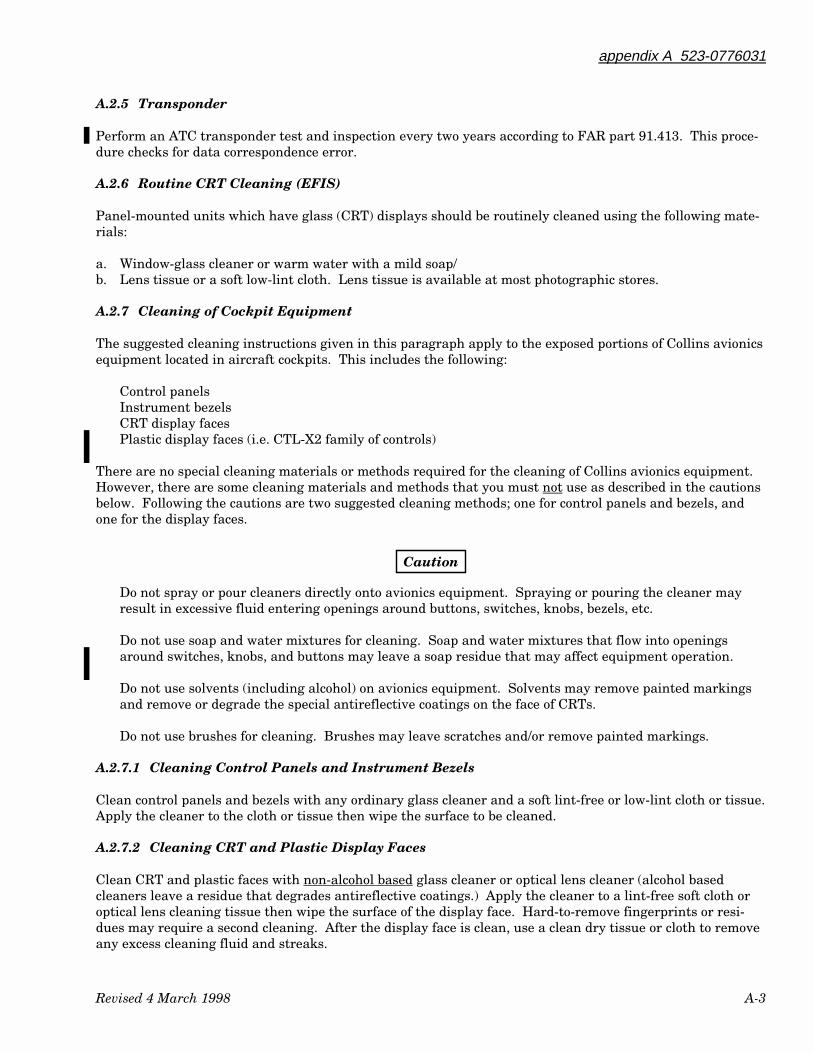
appendix A 523-0776031
Revised 4 March 1998 A-3
A.2.5 Transponder
Perform an ATC transponder test and inspection every two years according to FAR part 91.413. This proce-dure checks for data correspondence error.
A.2.6 Routine CRT Cleaning (EFIS)
Panel-mounted units which have glass (CRT) displays should be routinely cleaned using the following mate-rials:
a. Window-glass cleaner or warm water with a mild soap/b. Lens tissue or a soft low-lint cloth. Lens tissue is available at most photographic stores.
A.2.7 Cleaning of Cockpit Equipment
The suggested cleaning instructions given in this paragraph apply to the exposed portions of Collins avionicsequipment located in aircraft cockpits. This includes the following:
Control panelsInstrument bezelsCRT display facesPlastic display faces (i.e. CTL-X2 family of controls)
There are no special cleaning materials or methods required for the cleaning of Collins avionics equipment.However, there are some cleaning materials and methods that you must not use as described in the cautionsbelow. Following the cautions are two suggested cleaning methods; one for control panels and bezels, andone for the display faces.
Caution
Do not spray or pour cleaners directly onto avionics equipment. Spraying or pouring the cleaner mayresult in excessive fluid entering openings around buttons, switches, knobs, bezels, etc.
Do not use soap and water mixtures for cleaning. Soap and water mixtures that flow into openingsaround switches, knobs, and buttons may leave a soap residue that may affect equipment operation.
Do not use solvents (including alcohol) on avionics equipment. Solvents may remove painted markingsand remove or degrade the special antireflective coatings on the face of CRTs.
Do not use brushes for cleaning. Brushes may leave scratches and/or remove painted markings.
A.2.7.1 Cleaning Control Panels and Instrument Bezels
Clean control panels and bezels with any ordinary glass cleaner and a soft lint-free or low-lint cloth or tissue.Apply the cleaner to the cloth or tissue then wipe the surface to be cleaned.
A.2.7.2 Cleaning CRT and Plastic Display Faces
Clean CRT and plastic faces with non-alcohol based glass cleaner or optical lens cleaner (alcohol basedcleaners leave a residue that degrades antireflective coatings.) Apply the cleaner to a lint-free soft cloth oroptical lens cleaning tissue then wipe the surface of the display face. Hard-to-remove fingerprints or resi-dues may require a second cleaning. After the display face is clean, use a clean dry tissue or cloth to removeany excess cleaning fluid and streaks.
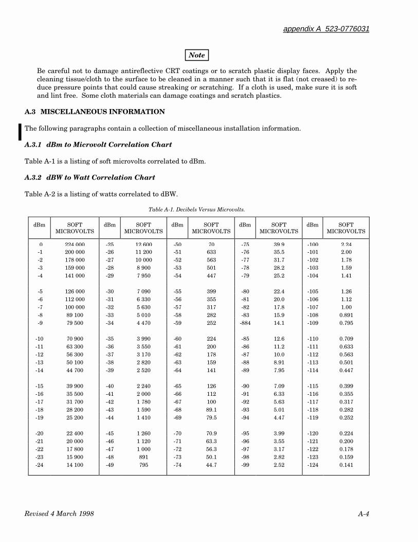
Revised 4 March 1998
appendix A 523-0776031
A-4
Note
Be careful not to damage antireflective CRT coatings or to scratch plastic display faces. Apply thecleaning tissue/cloth to the surface to be cleaned in a manner such that it is flat (not creased) to re-duce pressure points that could cause streaking or scratching. If a cloth is used, make sure it is softand lint free. Some cloth materials can damage coatings and scratch plastics.
A.3 MISCELLANEOUS INFORMATION
The following paragraphs contain a collection of miscellaneous installation information.
A.3.1 dBm to Microvolt Correlation Chart
Table A-1 is a listing of soft microvolts correlated to dBm.
A.3.2 dBW to Watt Correlation Chart
Table A-2 is a listing of watts correlated to dBW.
Table A-1. Decibels Versus Microvolts.
dBm SOFTMICROVOLTS
dBm SOFTMICROVOLTS
dBm SOFTMICROVOLTS
dBm SOFTMICROVOLTS
dBm SOFTMICROVOLTS
0 224 000 -25 12 600 -50 70 -75 39.9 -100 2.24 -1 200 000 -26 11 200 -51 633 -76 35.5 -101 2.00 -2 178 000 -27 10 000 -52 563 -77 31.7 -102 1.78 -3 159 000 -28 8 900 -53 501 -78 28.2 -103 1.59 -4 141 000 -29 7 950 -54 447 -79 25.2 -104 1.41
-5 126 000 -30 7 090 -55 399 -80 22.4 -105 1.26 -6 112 000 -31 6 330 -56 355 -81 20.0 -106 1.12 -7 100 000 -32 5 630 -57 317 -82 17.8 -107 1.00 -8 89 100 -33 5 010 -58 282 -83 15.9 -108 0.891 -9 79 500 -34 4 470 -59 252 -884 14.1 -109 0.795
-10 70 900 -35 3 990 -60 224 -85 12.6 -110 0.709-11 63 300 -36 3 550 -61 200 -86 11.2 -111 0.633-12 56 300 -37 3 170 -62 178 -87 10.0 -112 0.563-13 50 100 -38 2 820 -63 159 -88 8.91 -113 0.501-14 44 700 -39 2 520 -64 141 -89 7.95 -114 0.447
-15 39 900 -40 2 240 -65 126 -90 7.09 -115 0.399-16 35 500 -41 2 000 -66 112 -91 6.33 -116 0.355-17 31 700 -42 1 780 -67 100 -92 5.63 -117 0.317-18 28 200 -43 1 590 -68 89.1 -93 5.01 -118 0.282-19 25 200 -44 1 410 -69 79.5 -94 4.47 -119 0.252
-20 22 400 -45 1 260 -70 70.9 -95 3.99 -120 0.224-21 20 000 -46 1 120 -71 63.3 -96 3.55 -121 0.200-22 17 800 -47 1 000 -72 56.3 -97 3.17 -122 0.178-23 15 900 -48 891 -73 50.1 -98 2.82 -123 0.159-24 14 100 -49 795 -74 44.7 -99 2.52 -124 0.141

appendix A 523-0776031
Revised 4 March 1998 A-5
Table A-2. Decibels Versus Watts.
dBW WATTS dBW WATTS dBW WATTS dBW WATTS dBW WATTS
0 1.0 15 31.62 22 158.5 29 794.3 36 39817 5.01 16 39.81 23 199.5 30 1000 40 10 000
10 10.00 17 50.12 24 251.2 31 125911 12.59 18 63.10 25 316.2 32 158512 15.85 19 79.43 26 398.1 33 199513 19.95 20 100.0 27 501.2 34 251214 25.12 21 125.9 28 631.0 35 3162

Revised 4 March 1998
appendix A 523-0776031
A-6
This page intentionally blank.
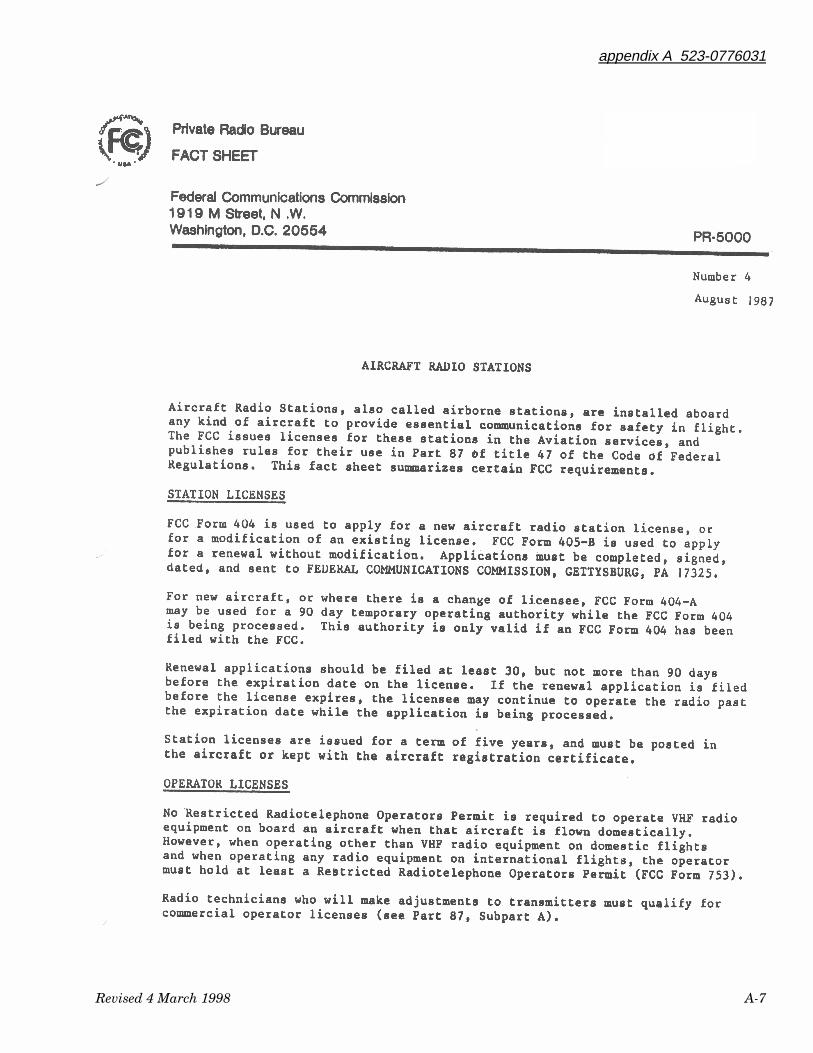
appendix A 523-0776031
Revised 4 March 1998 A-7
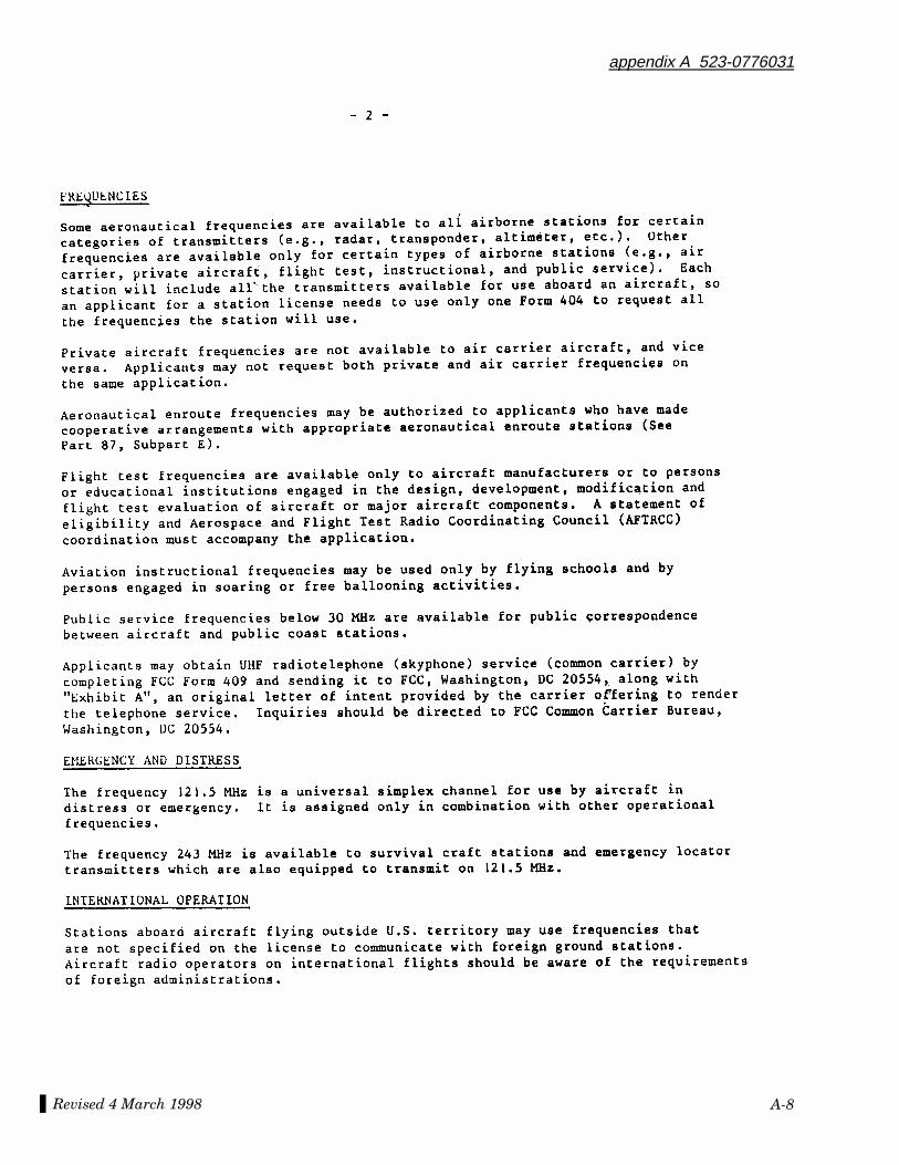
Revised 4 March 1998
appendix A 523-0776031
A-8
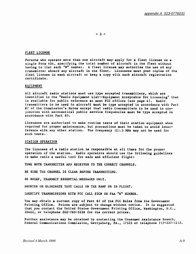
appendix A 523-0776031
Revised 4 March 1998 A-9
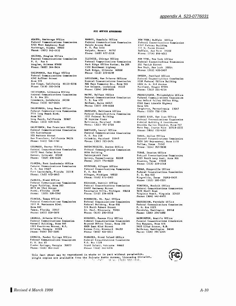
Revised 4 March 1998
appendix A 523-0776031
A-10
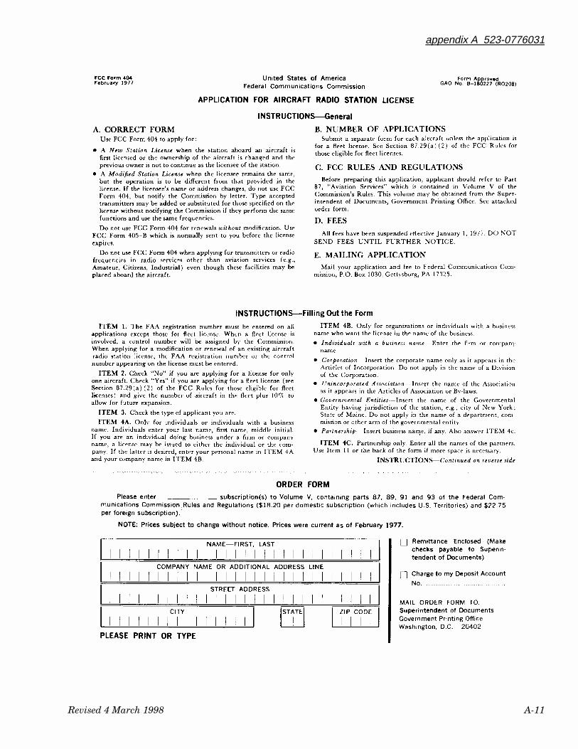
appendix A 523-0776031
Revised 4 March 1998 A-11
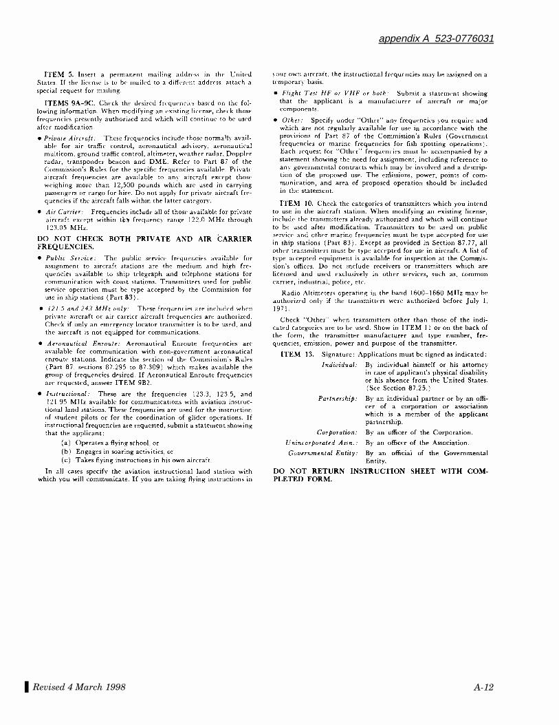
Revised 4 March 1998
appendix A 523-0776031
A-12
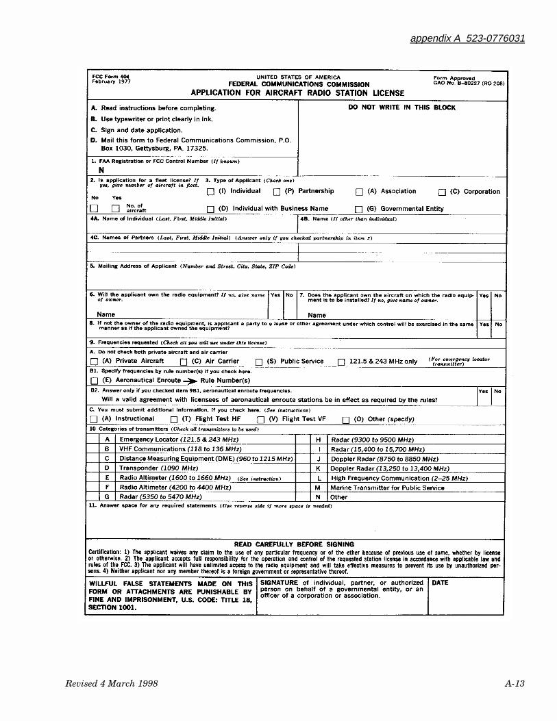
appendix A 523-0776031
Revised 4 March 1998 A-13
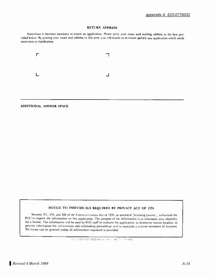
Revised 4 March 1998
appendix A 523-0776031
A-14
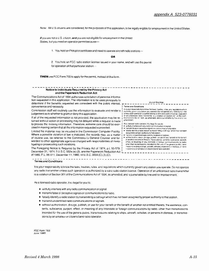
appendix A 523-0776031
Revised 4 March 1998 A-15
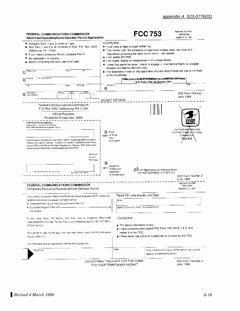
Revised 4 March 1998
appendix A 523-0776031
A-16
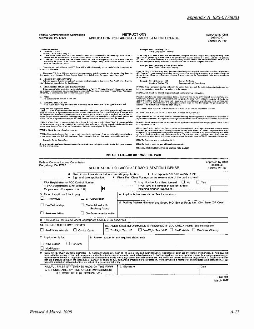
appendix A 523-0776031
Revised 4 March 1998 A-17
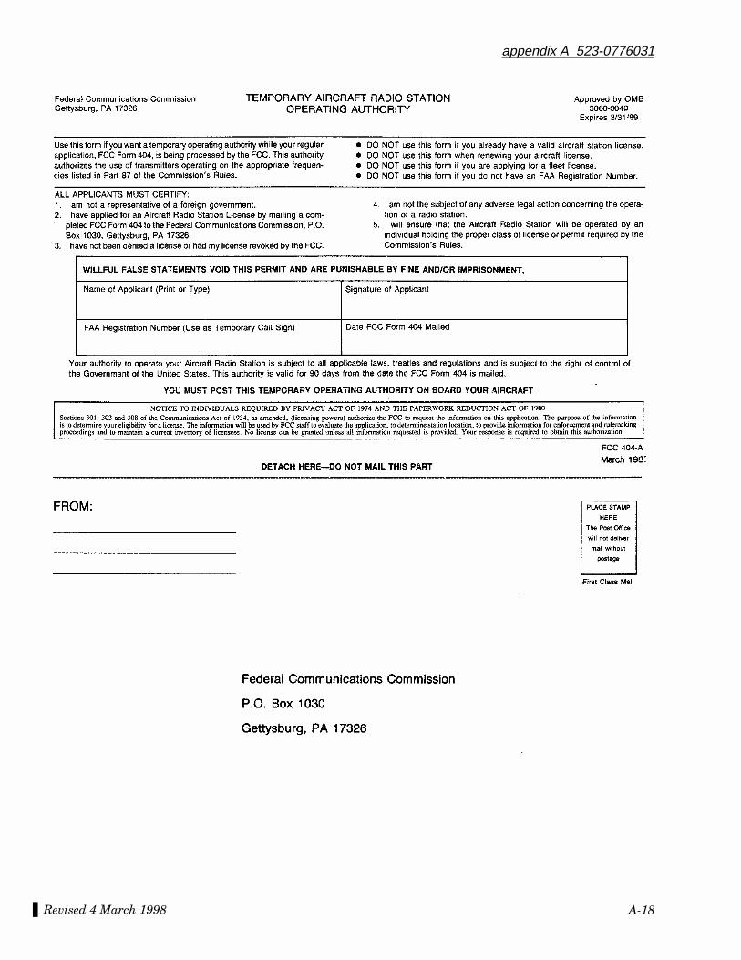
Revised 4 March 1998
appendix A 523-0776031
A-18
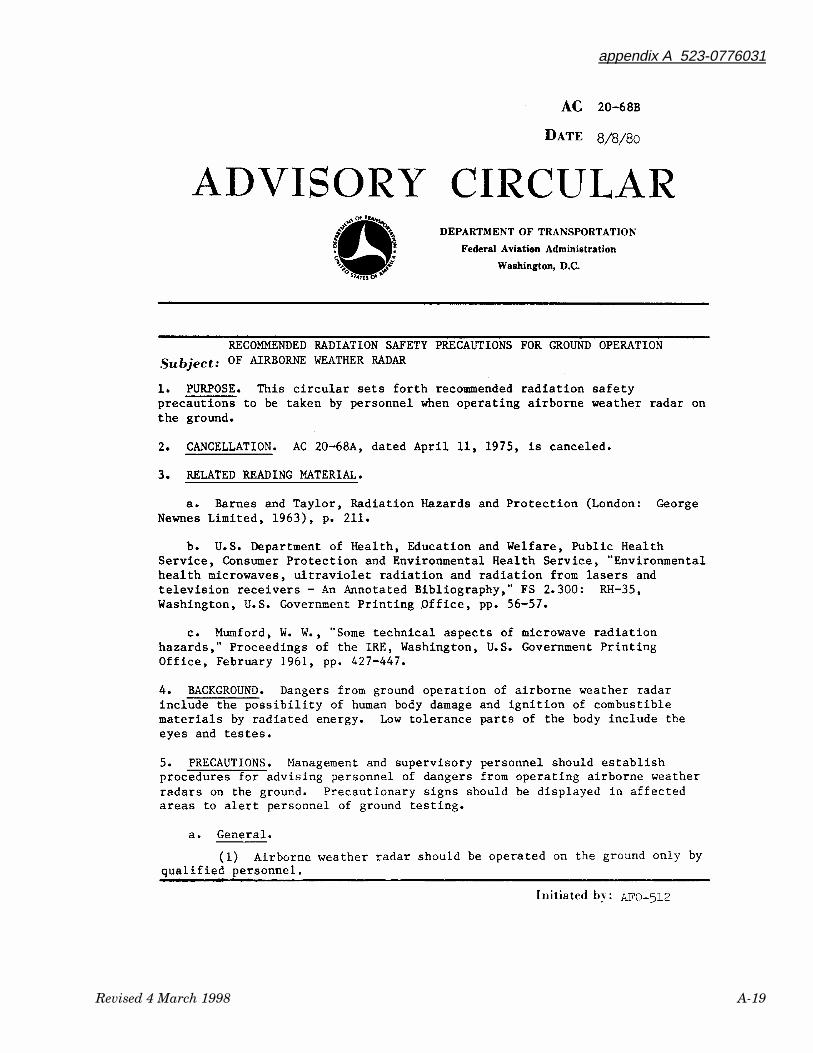
appendix A 523-0776031
Revised 4 March 1998 A-19
Revised 4 March 1998
appendix A 523-0776031
A-20
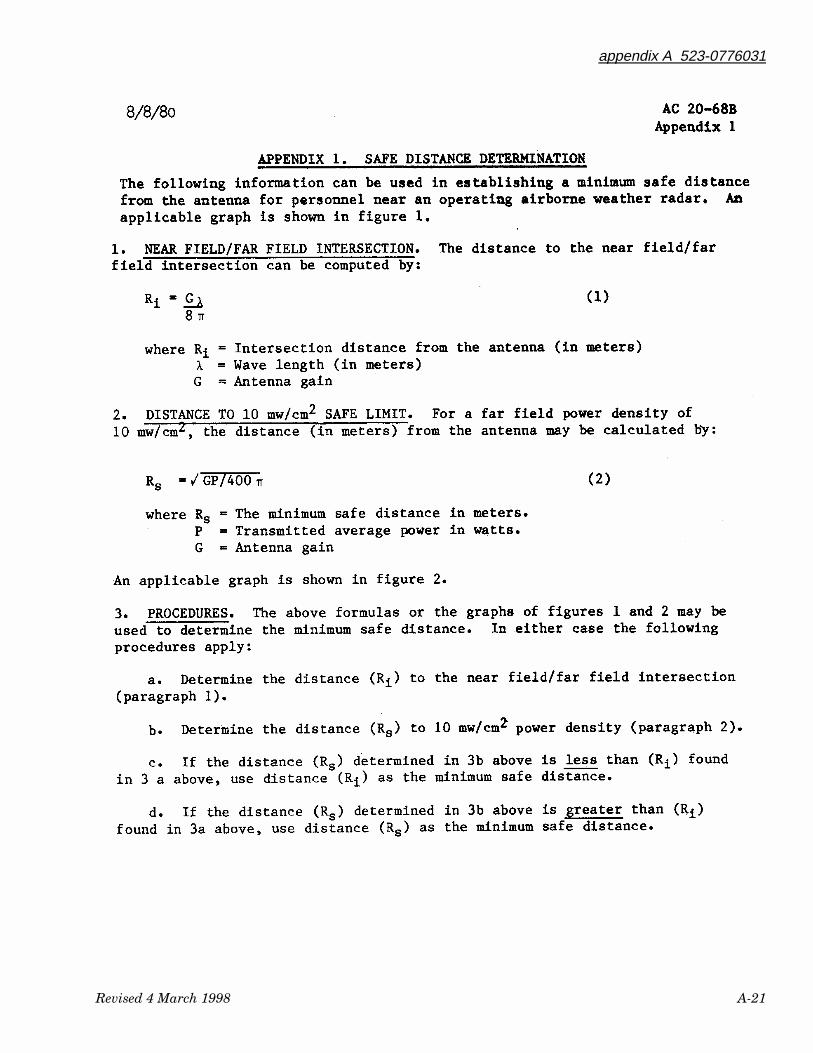
appendix A 523-0776031
Revised 4 March 1998 A-21
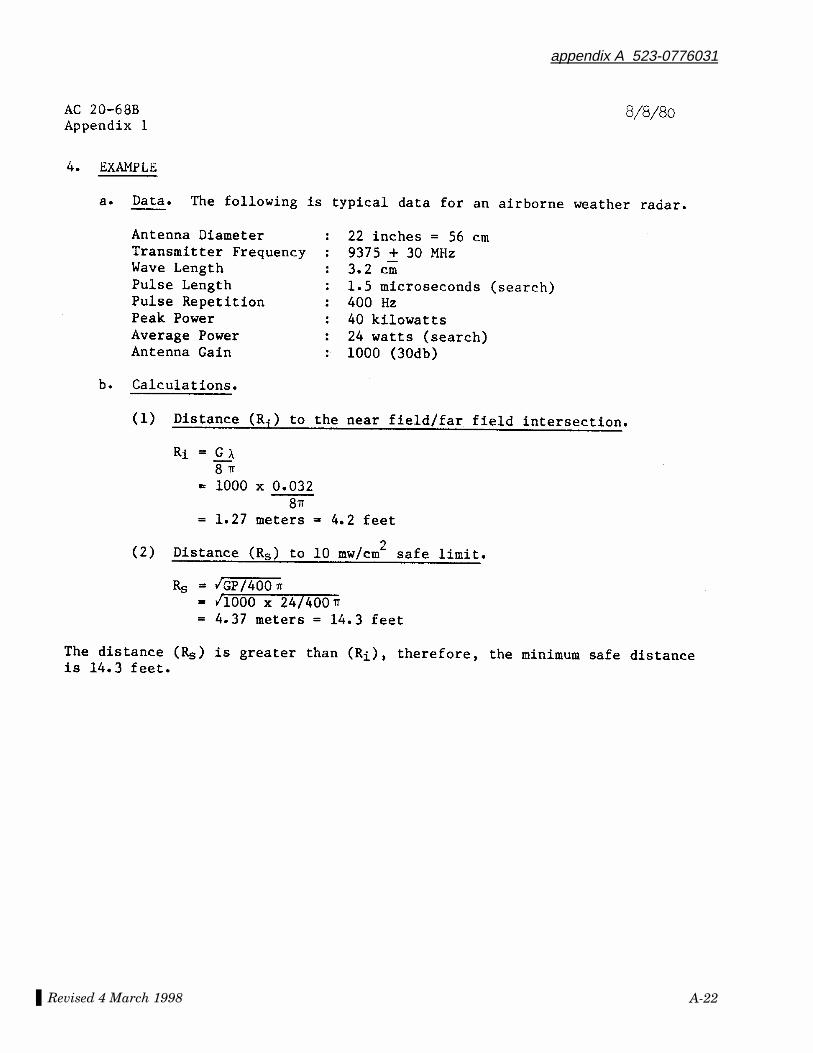
Revised 4 March 1998
appendix A 523-0776031
A-22
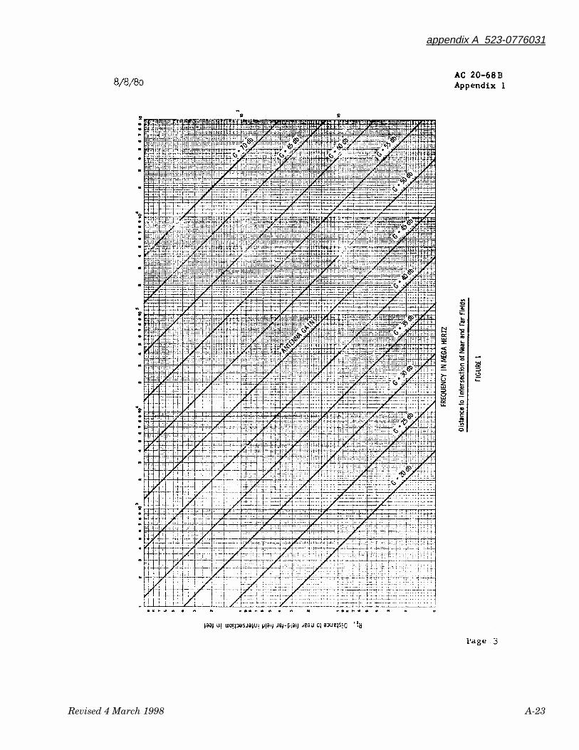
appendix A 523-0776031
Revised 4 March 1998 A-23

Revised 4 March 1998
appendix A 523-0776031
A-24
appendix A 523-0776031
Revised 4 March 1998 A-25
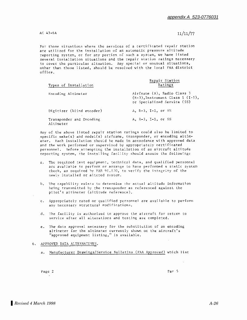
Revised 4 March 1998
appendix A 523-0776031
A-26
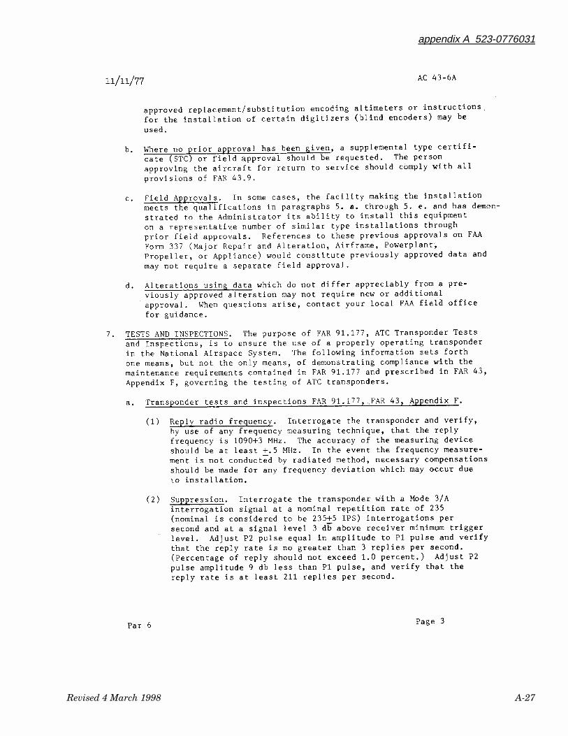
appendix A 523-0776031
Revised 4 March 1998 A-27
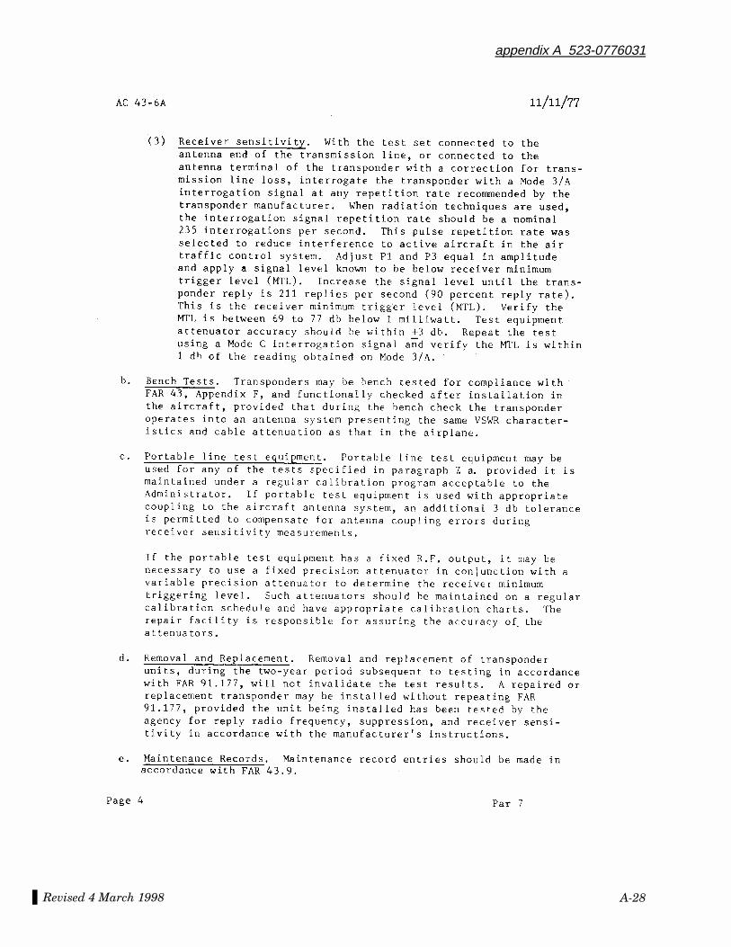
Revised 4 March 1998
appendix A 523-0776031
A-28
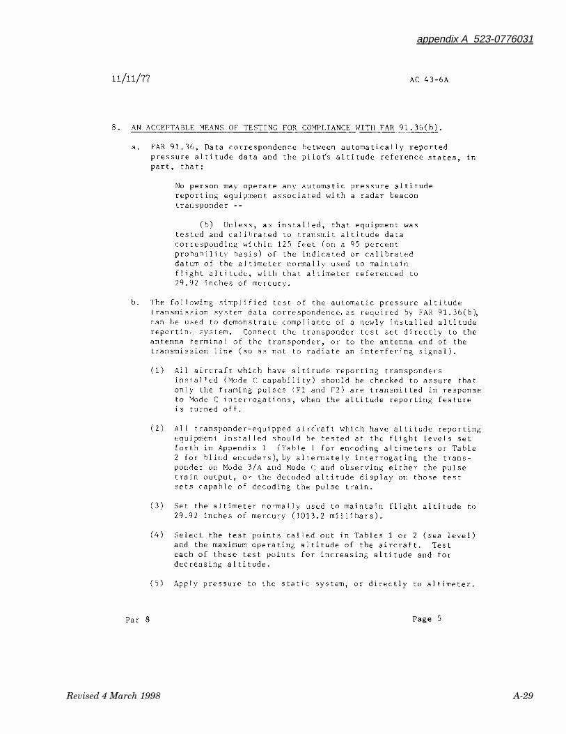
appendix A 523-0776031
Revised 4 March 1998 A-29
Revised 4 March 1998
appendix A 523-0776031
A-30
appendix A 523-0776031
Revised 4 March 1998 A-31
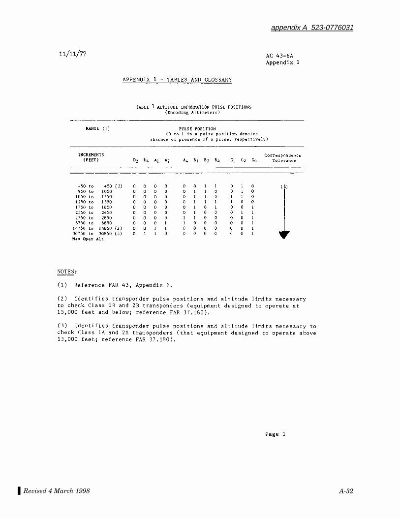
Revised 4 March 1998
appendix A 523-0776031
A-32
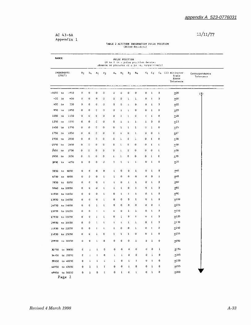
appendix A 523-0776031
Revised 4 March 1998 A-33
Revised 4 March 1998
appendix A 523-0776031
A-34
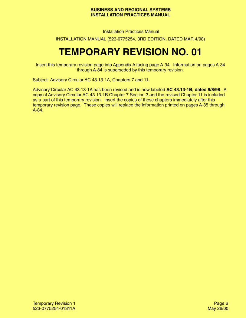
BUSINESS AND REGIONAL SYSTEMSINSTALLATION PRACTICES MANUAL
Temporary Revision 1523-0775254-01311A May 26/00
Installation Practices Manual
INSTALLATION MANUAL (523-0775254, 3RD EDITION, DATED MAR 4/98)
TEMPORARY REVISION NO. 01Insert this temporary revision page into Appendix A facing page A-34. Information on pages A-34
through A-84 is superseded by this temporary revision.
Subject: Advisory Circular AC 43.13-1A, Chapters 7 and 11.
Advisory Circular AC 43.13-1A has been revised and is now labeled AC 43.13-1B, dated 9/8/98. Acopy of Advisory Circular AC 43.13-1B Chapter 7 Section 3 and the revised Chapter 11 is includedas a part of this temporary revision. Insert the copies of these chapters immediately after thistemporary revision page. These copies will replace the information printed on pages A-35 throughA-84.
Page 6
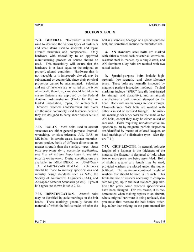
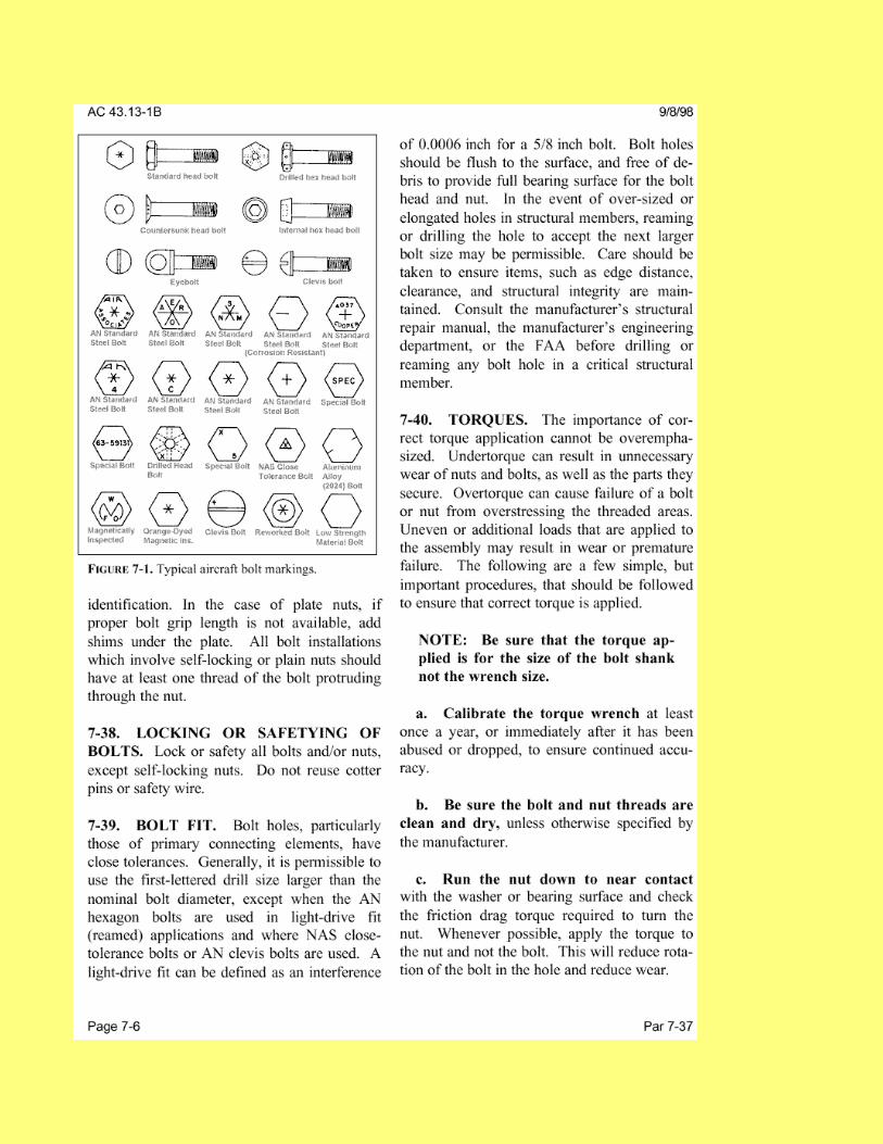
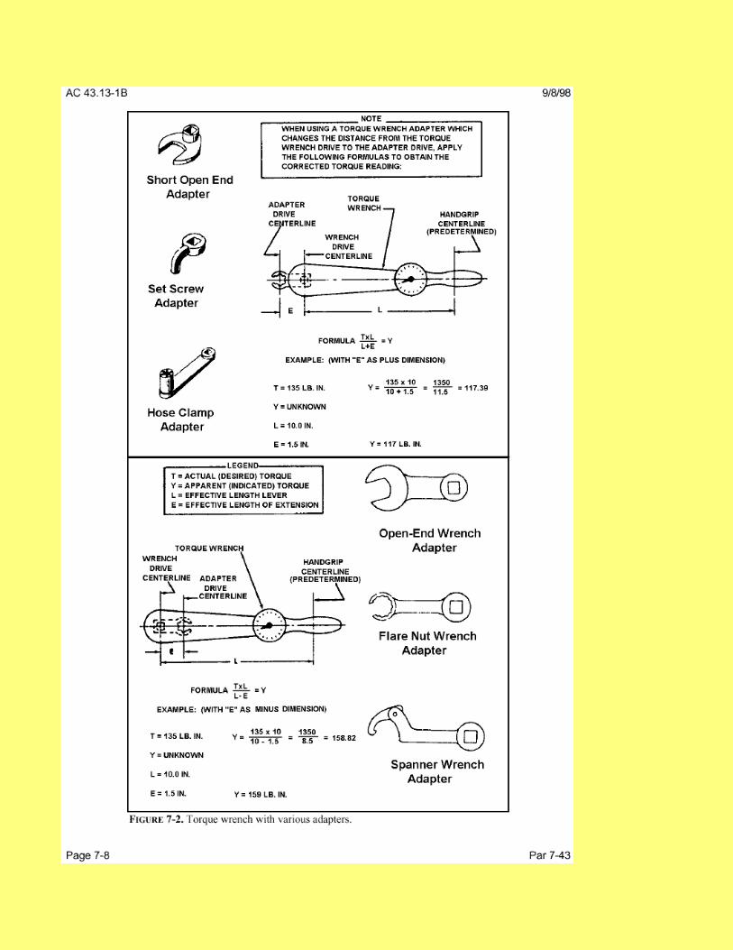
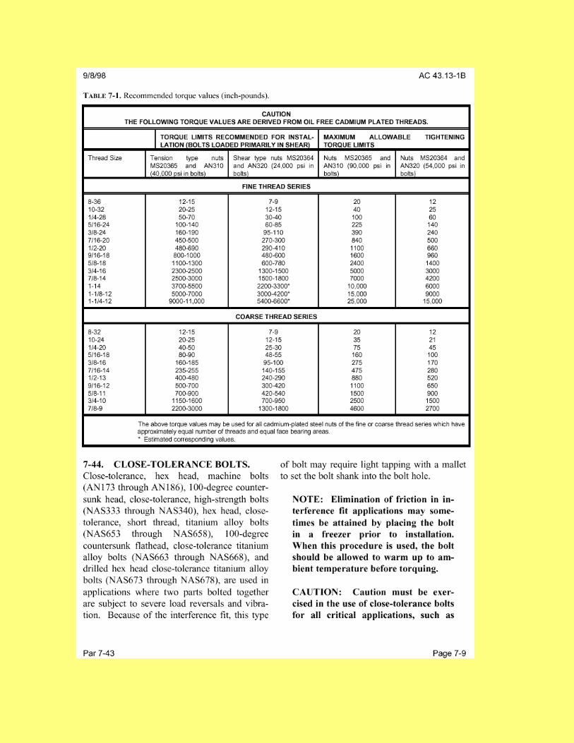
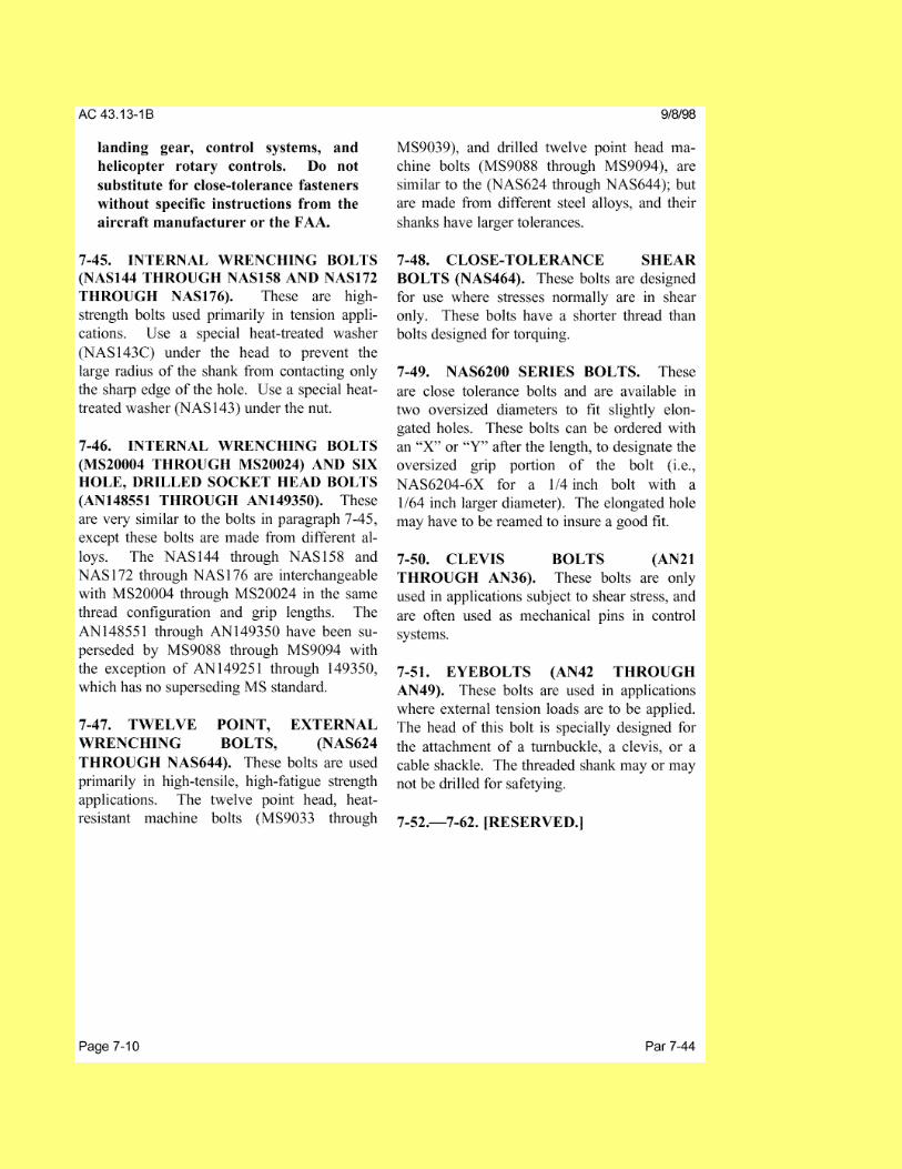

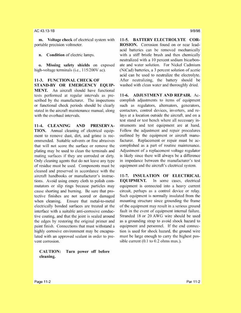
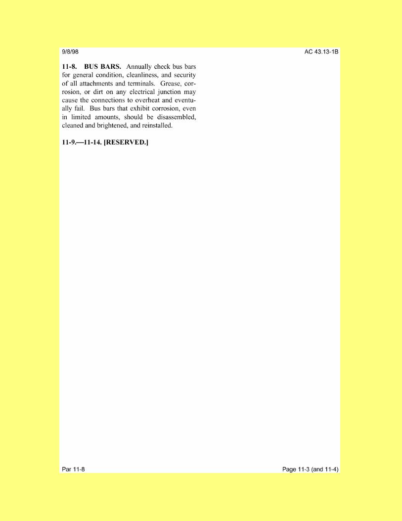
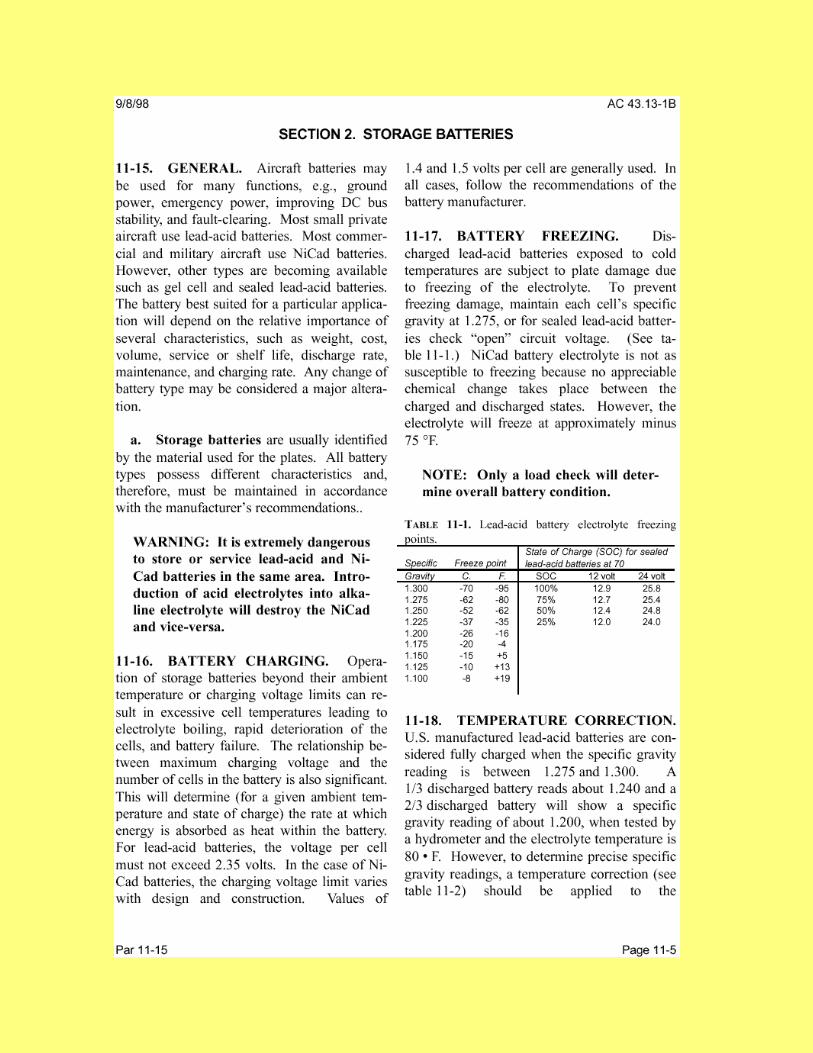
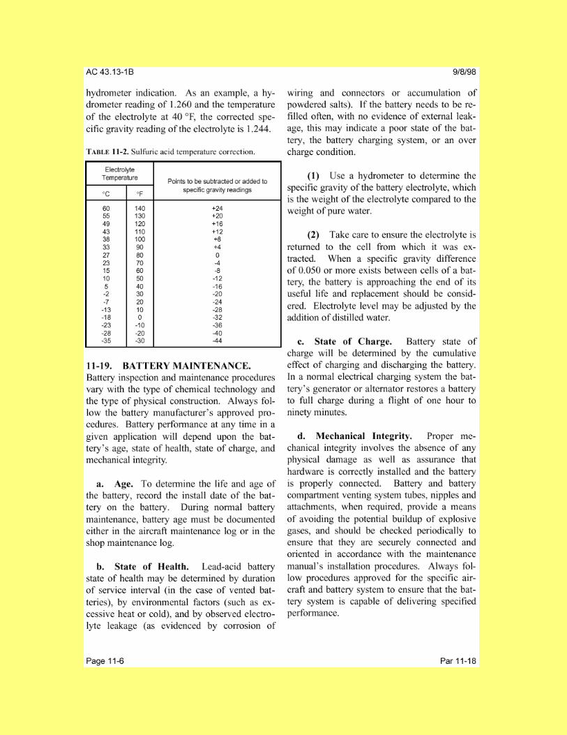

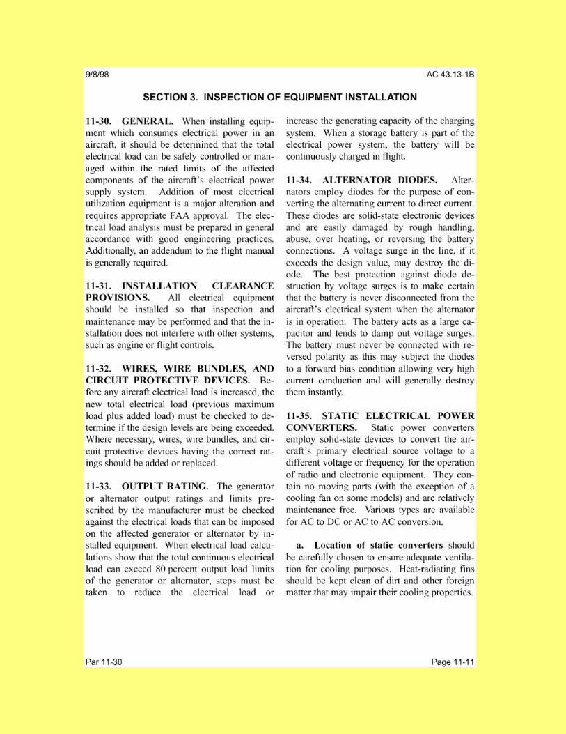
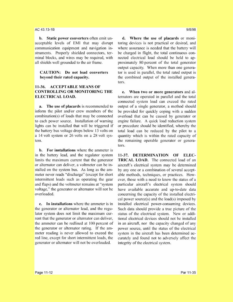

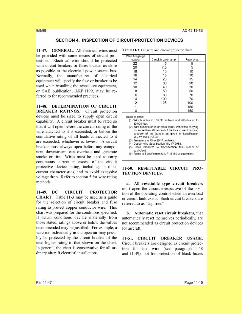

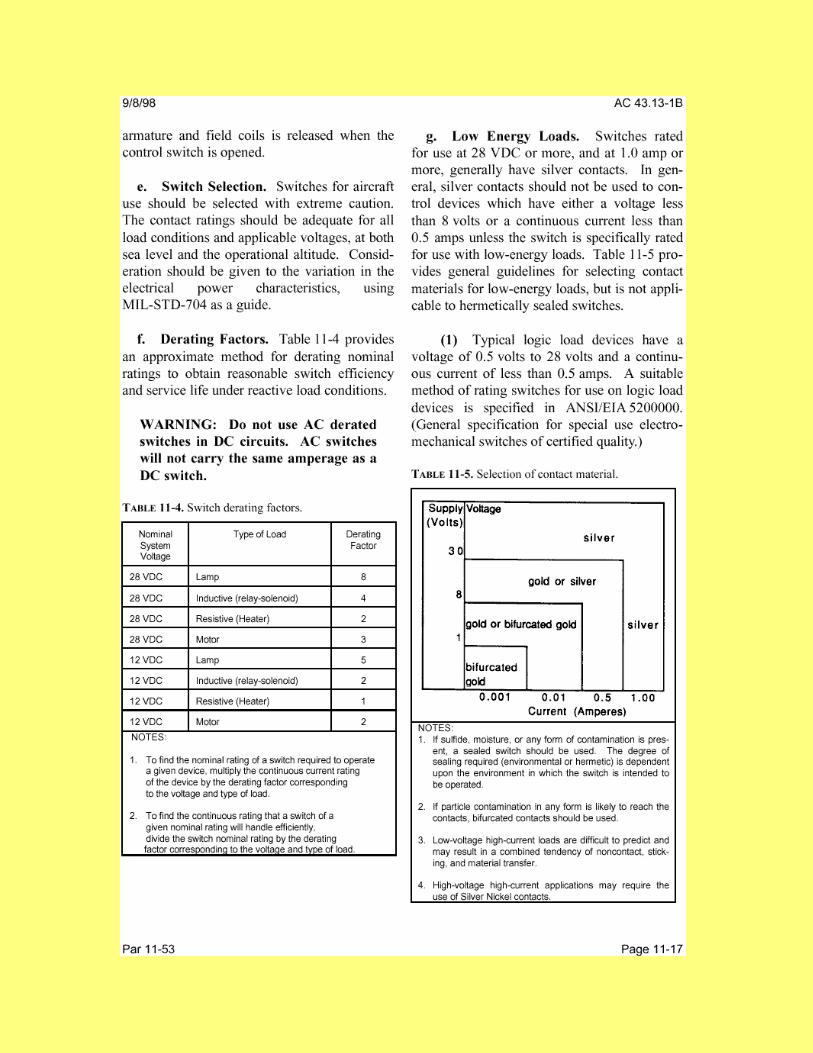
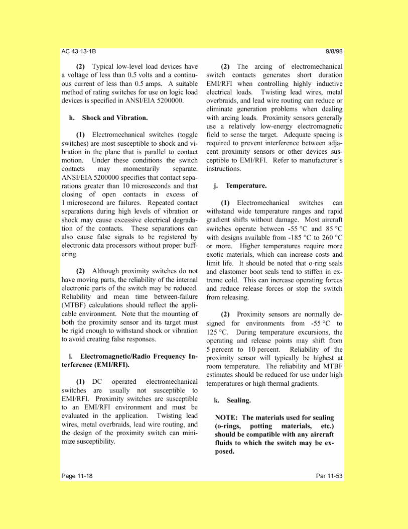
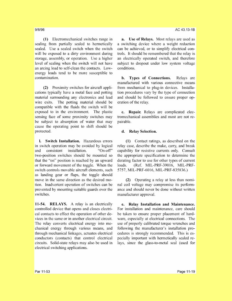
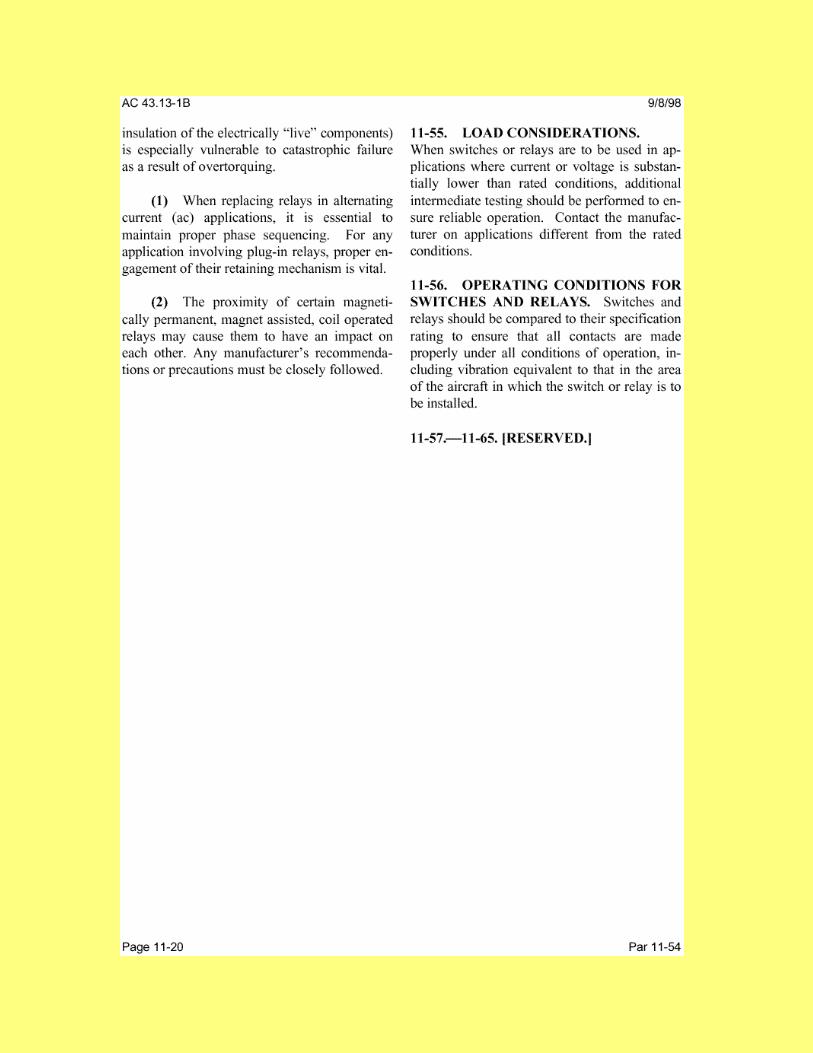
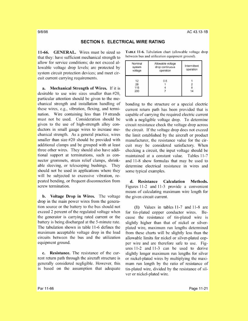
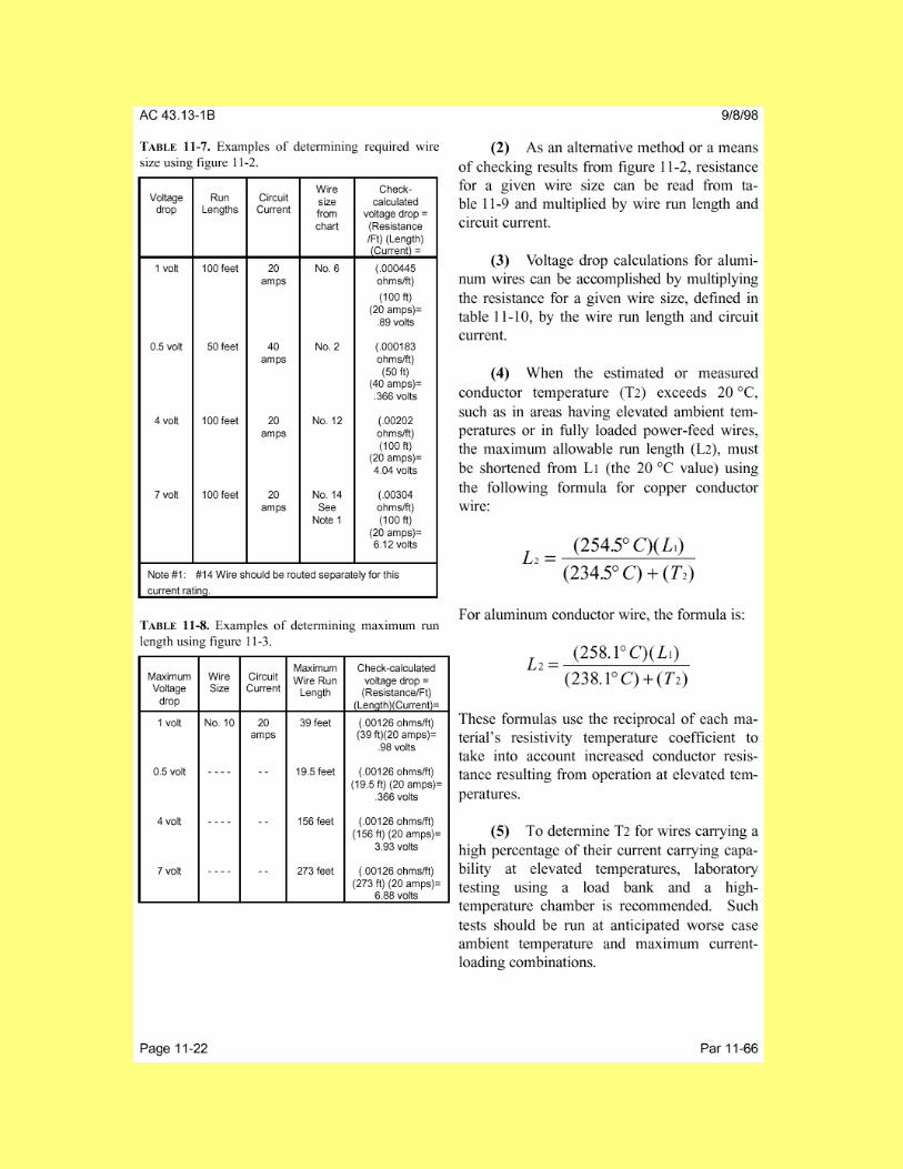
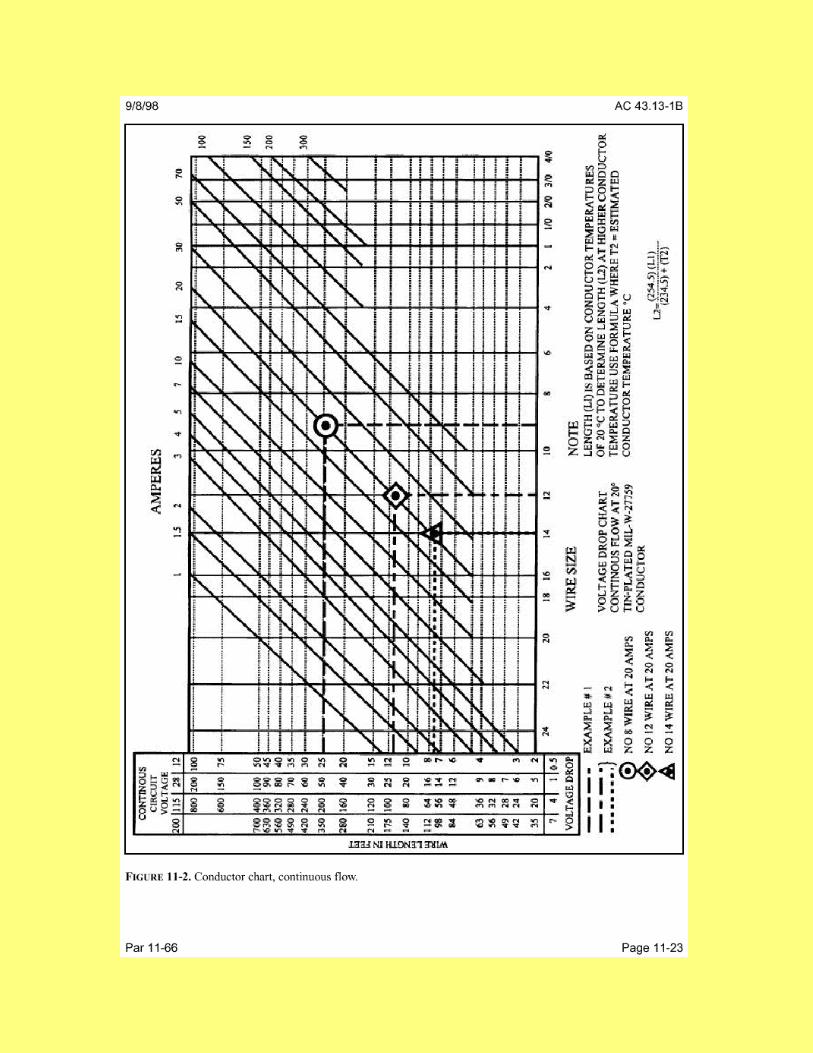
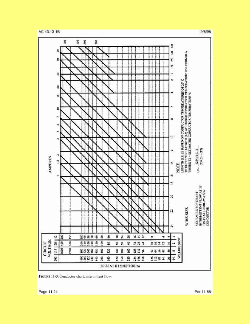
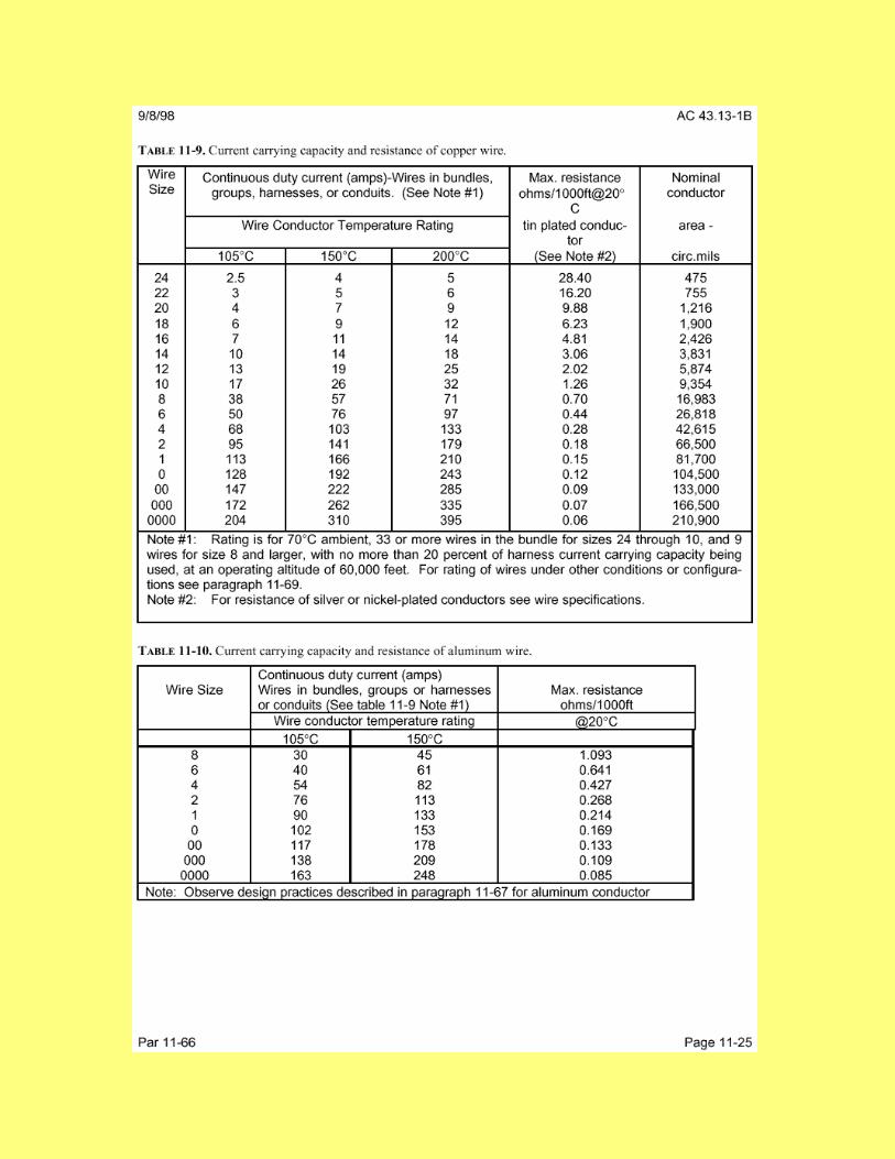

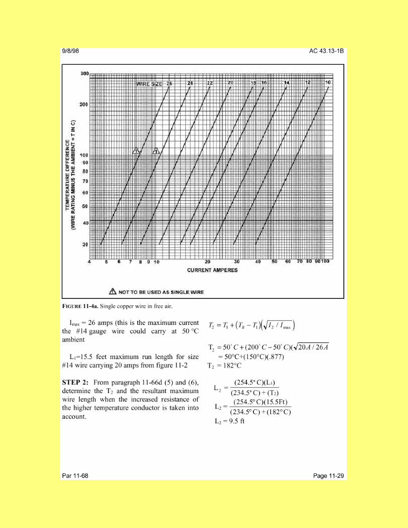
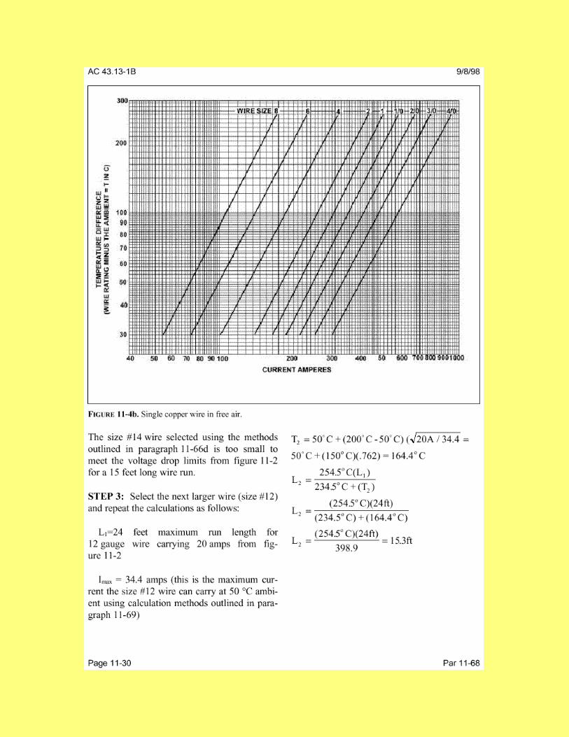
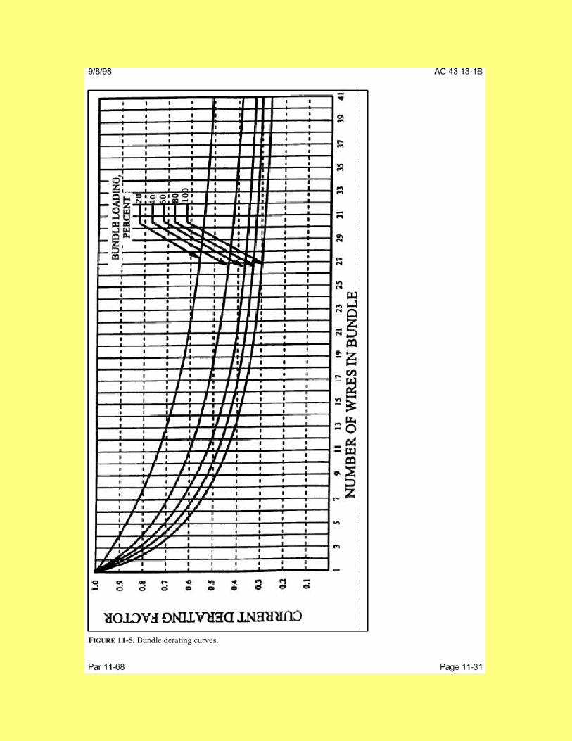
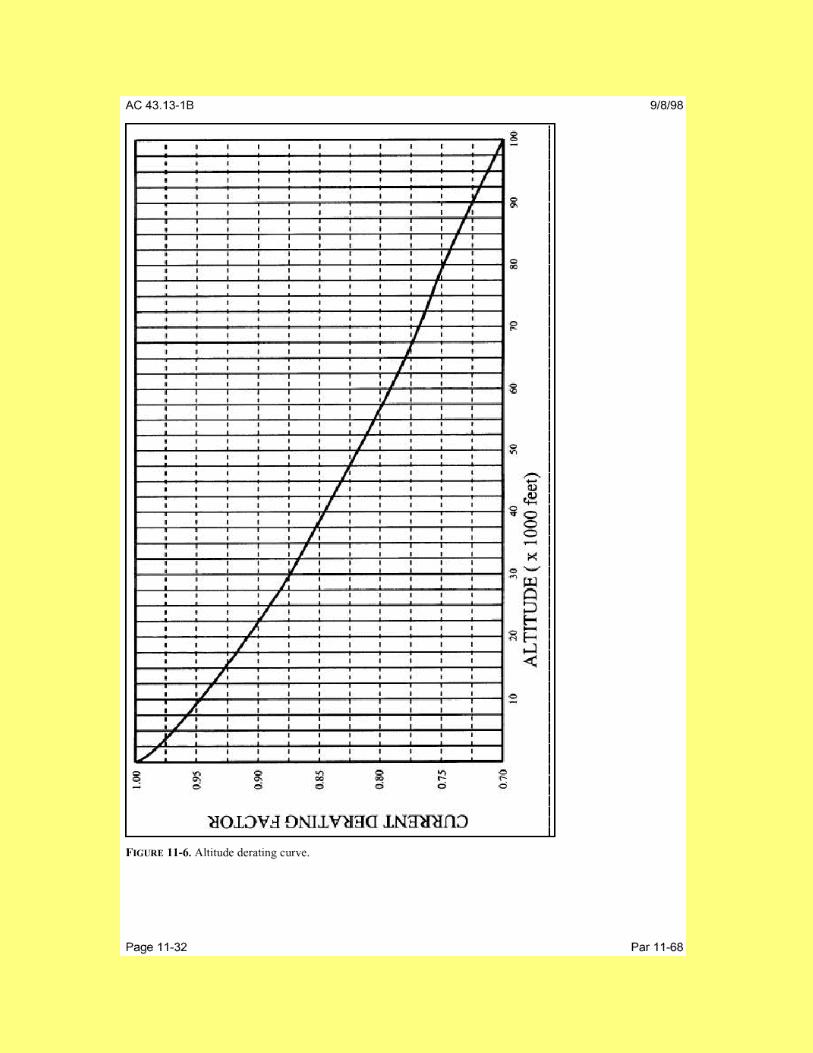


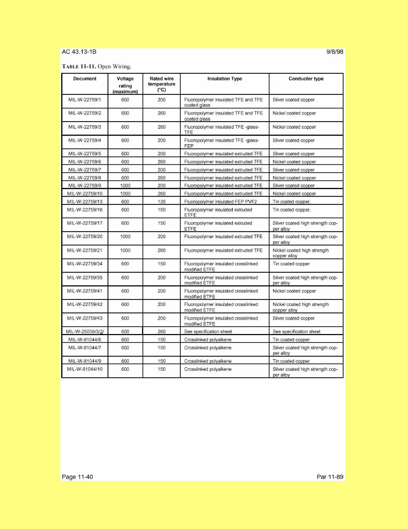
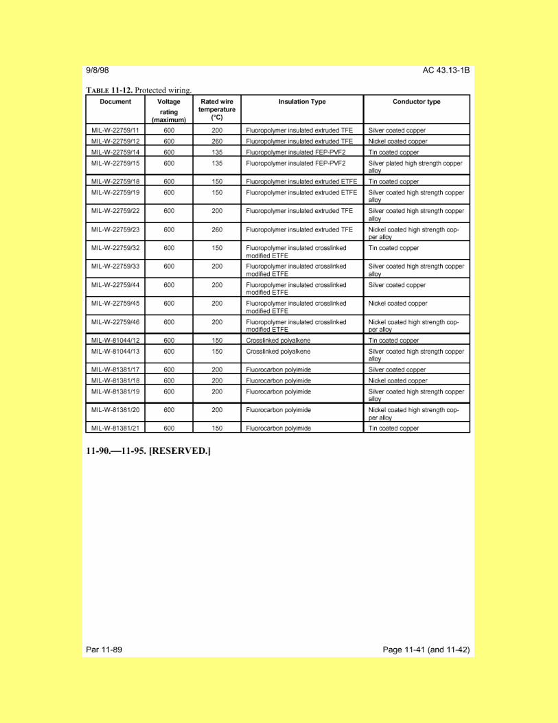
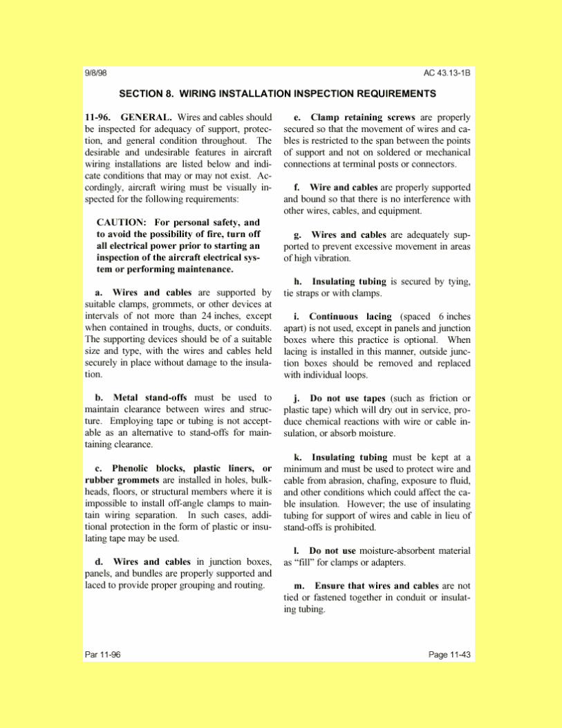
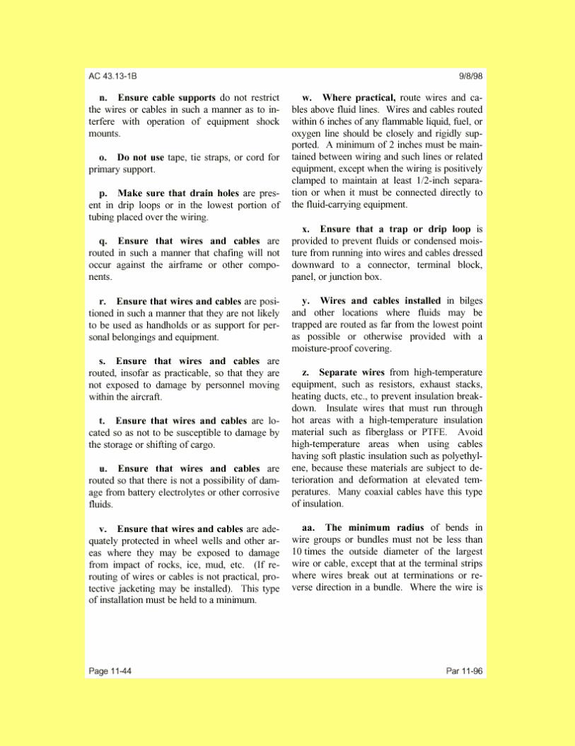
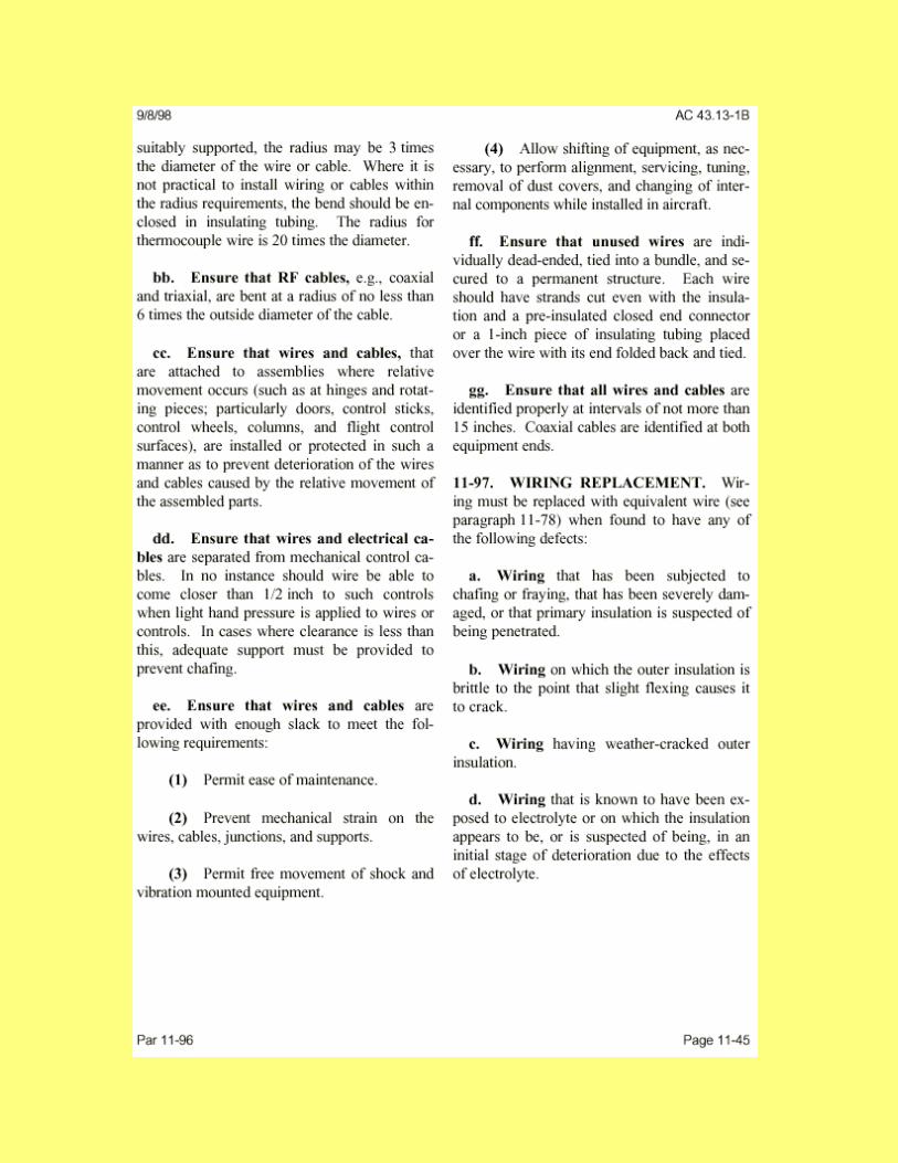

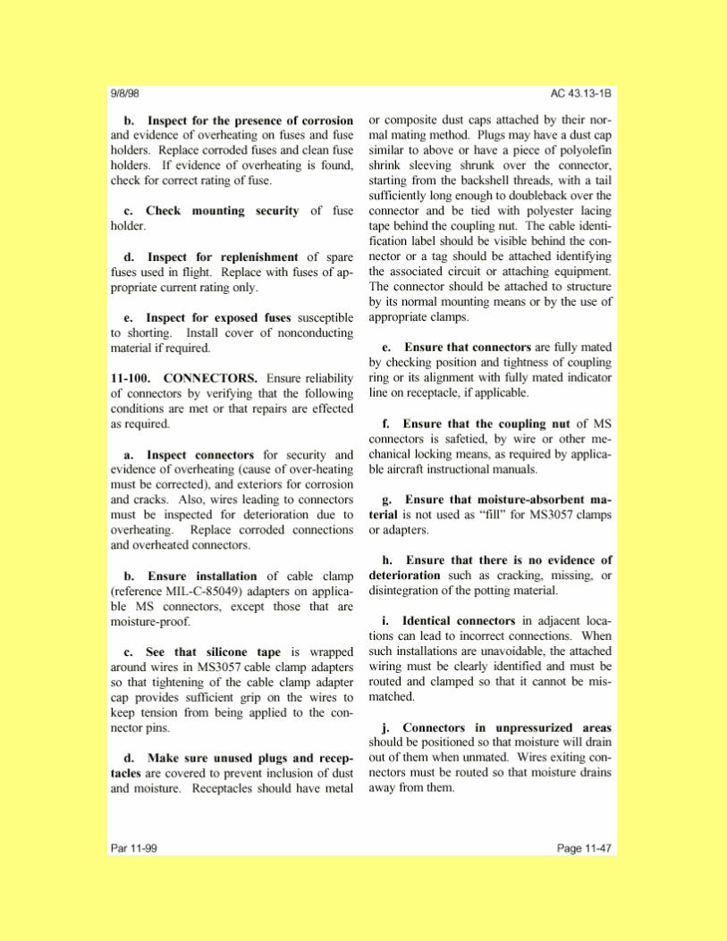

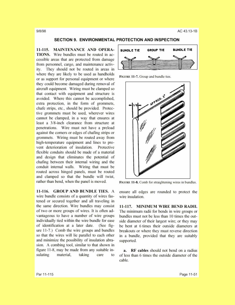

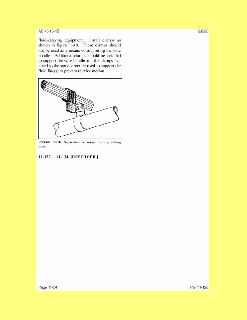
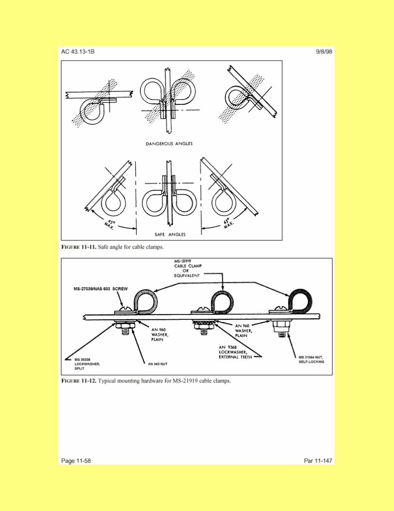
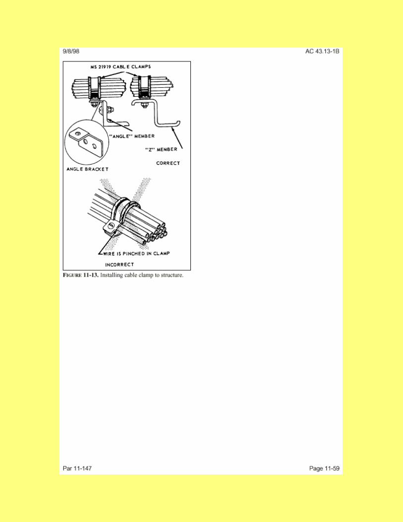
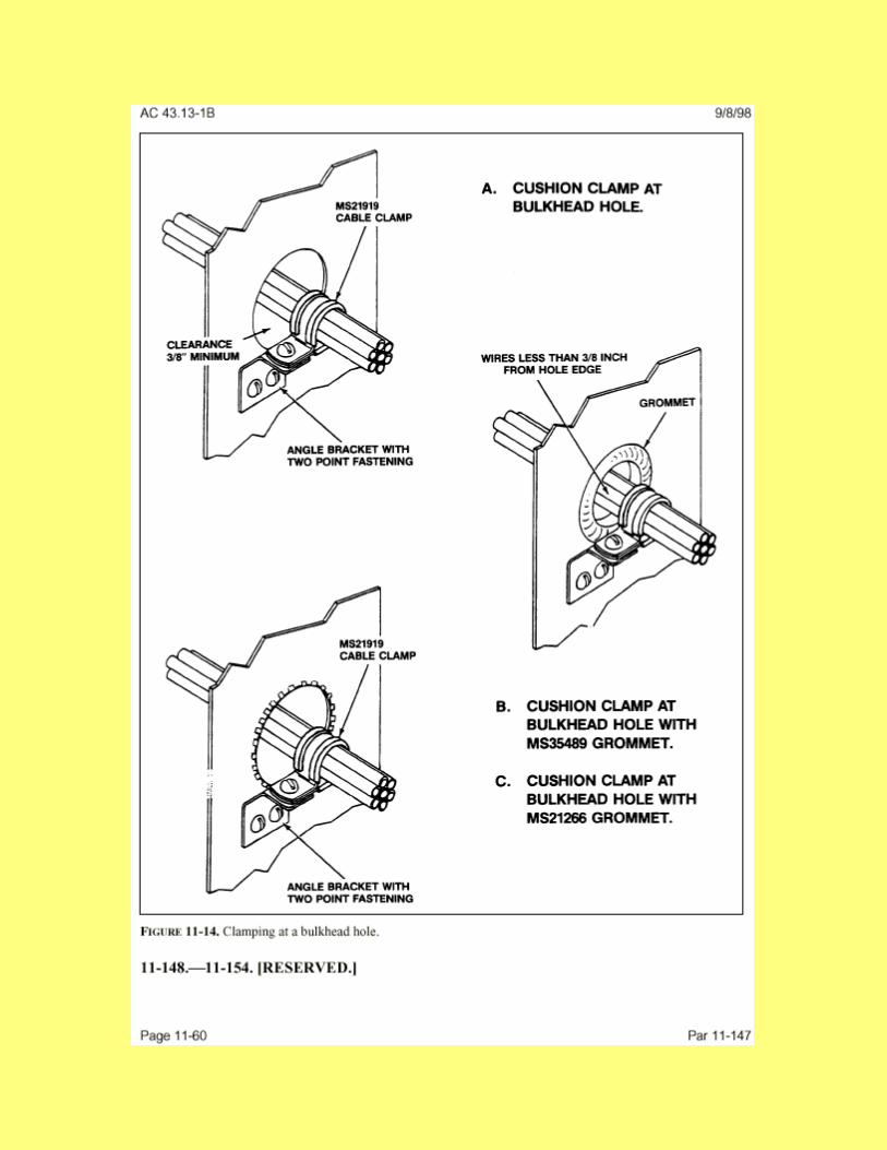
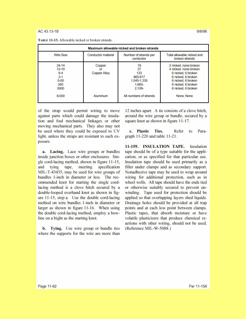
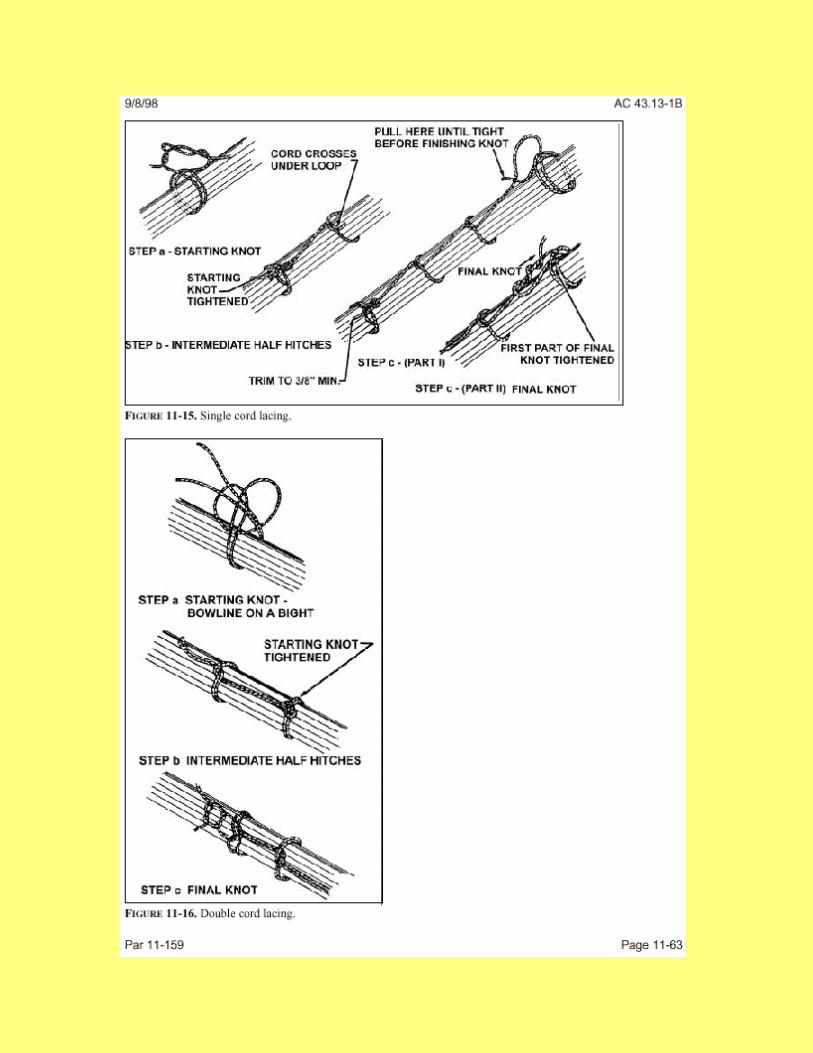

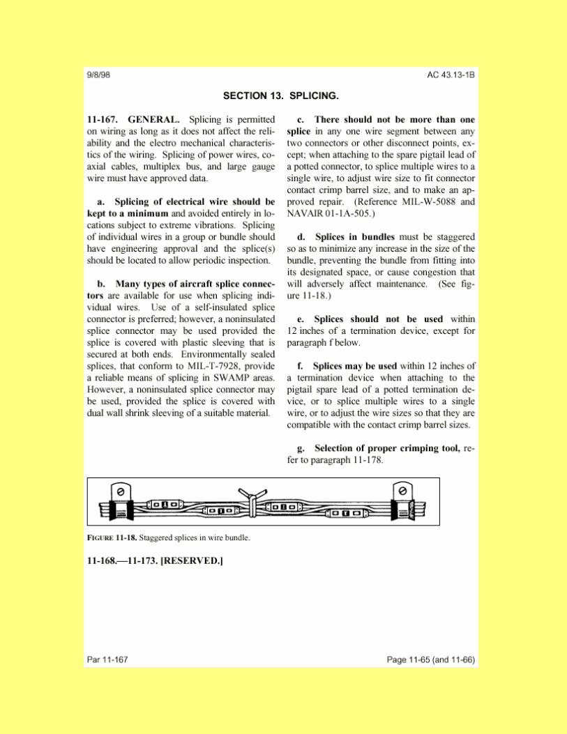
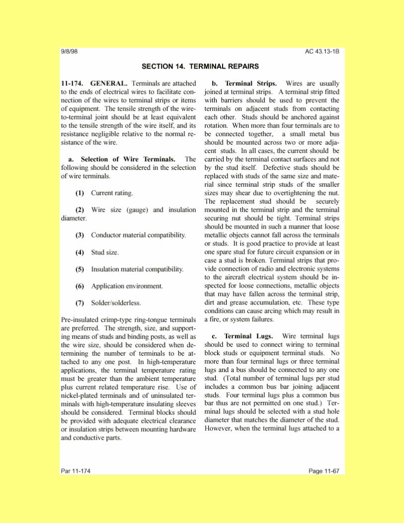
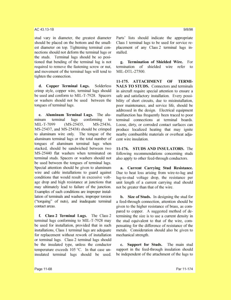
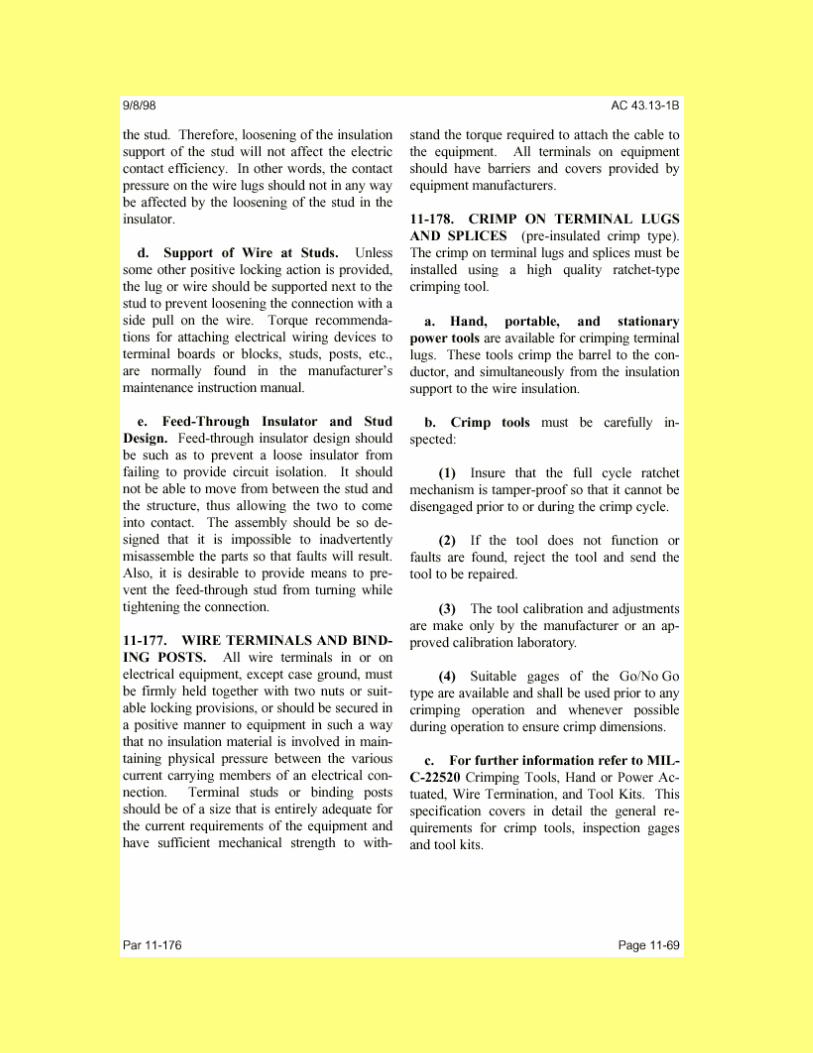
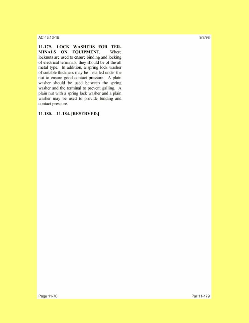
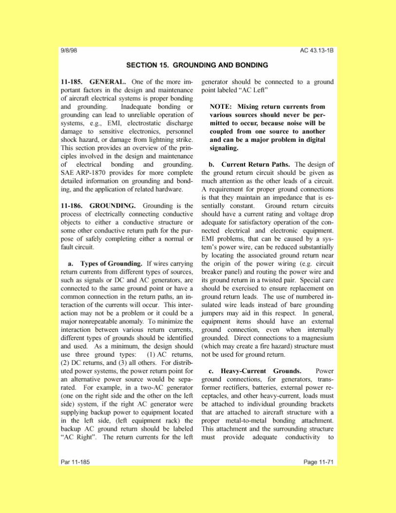
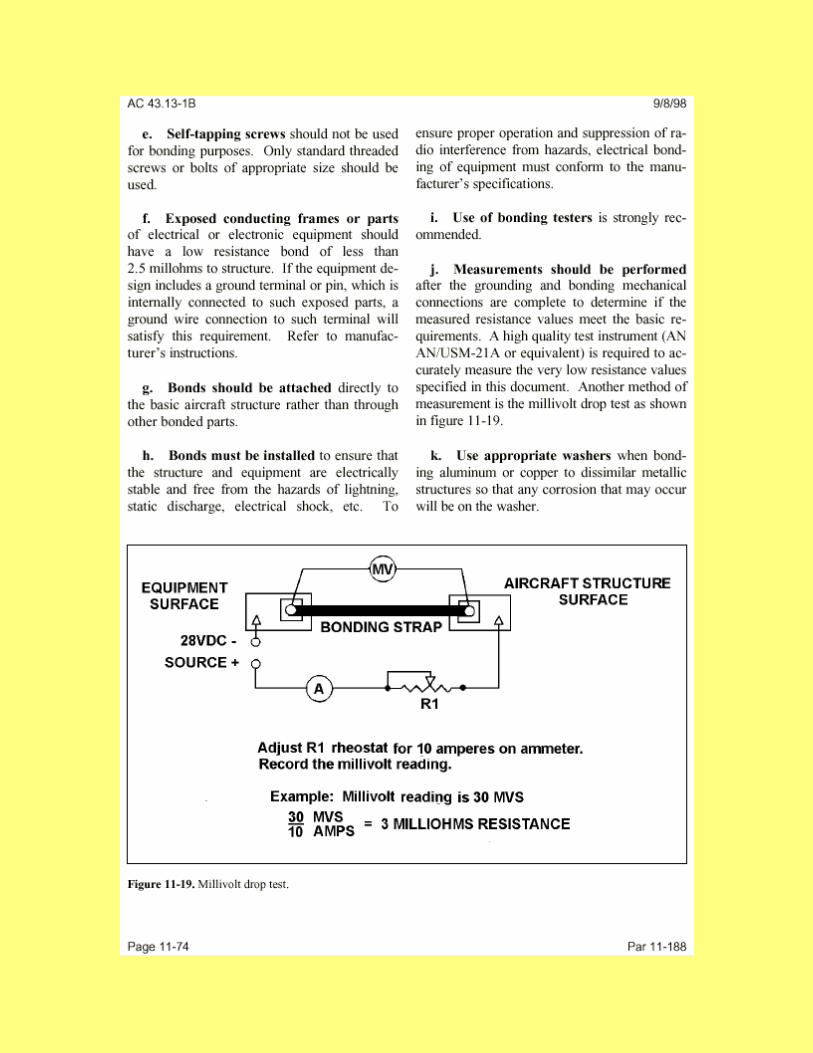
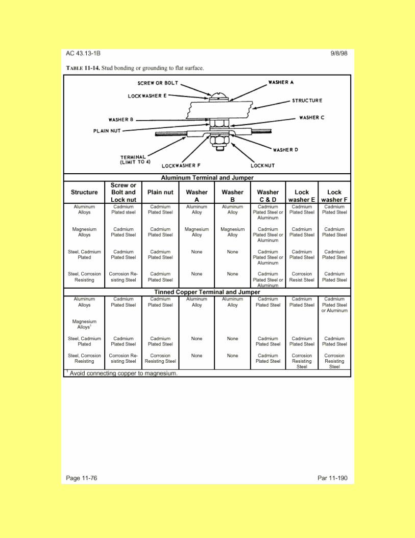
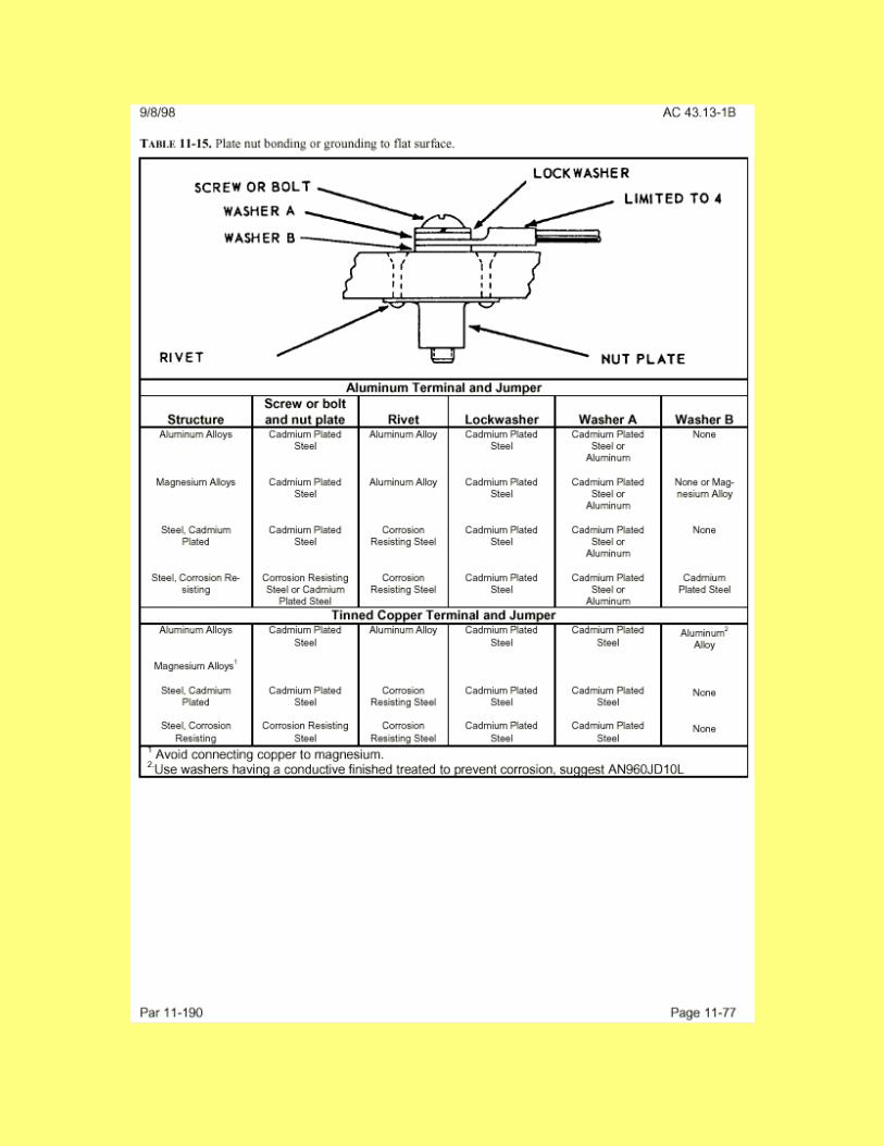
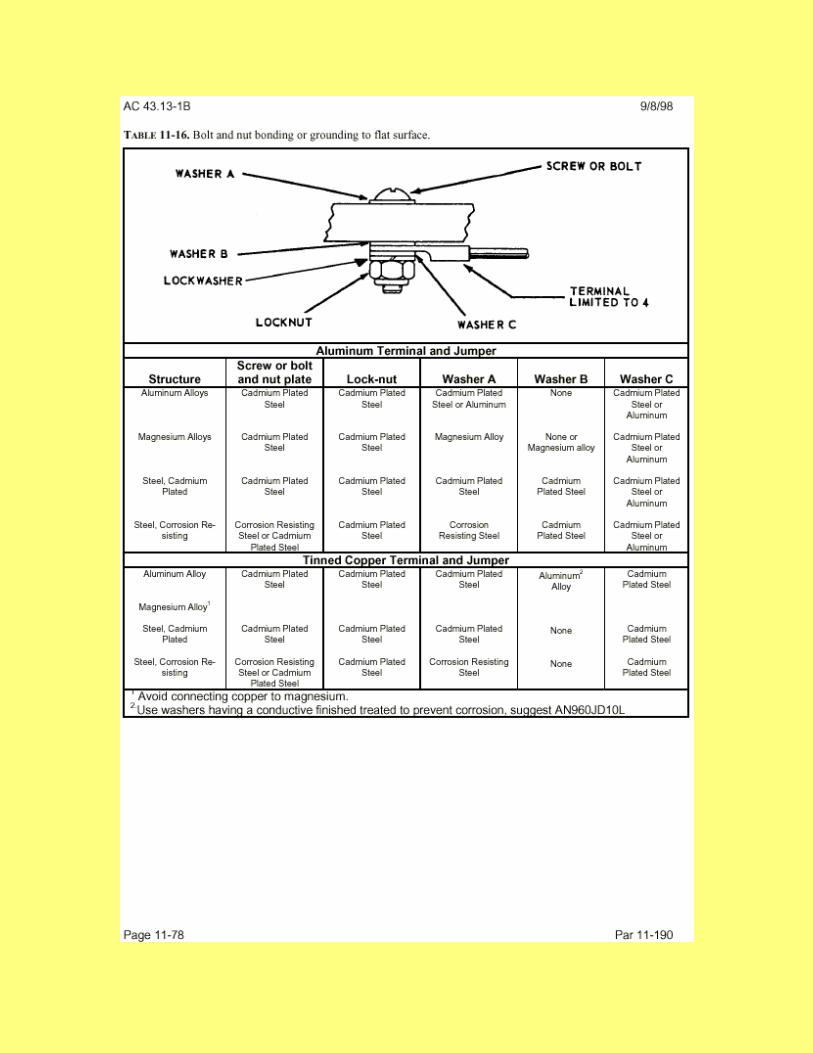
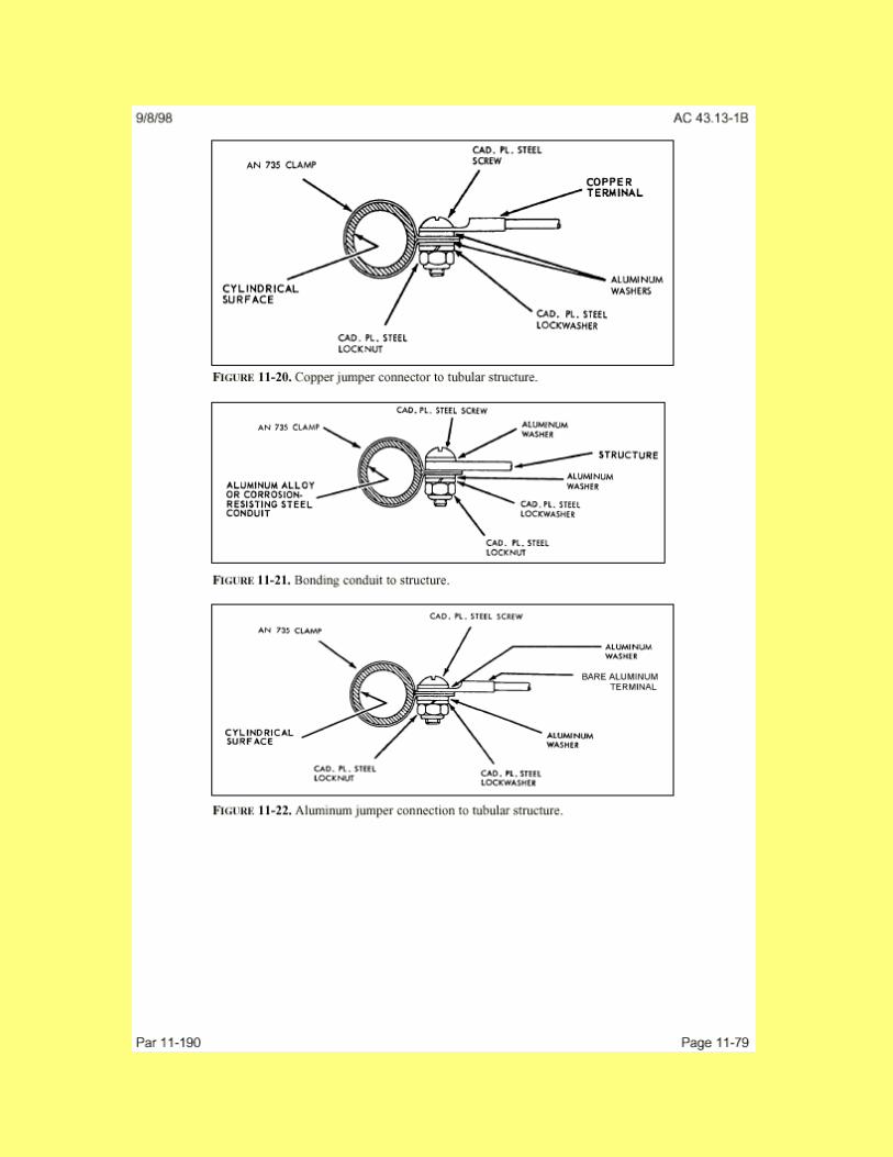
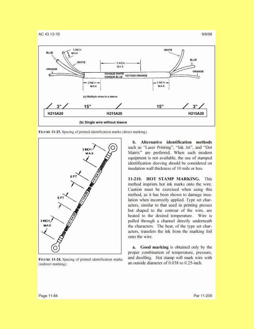
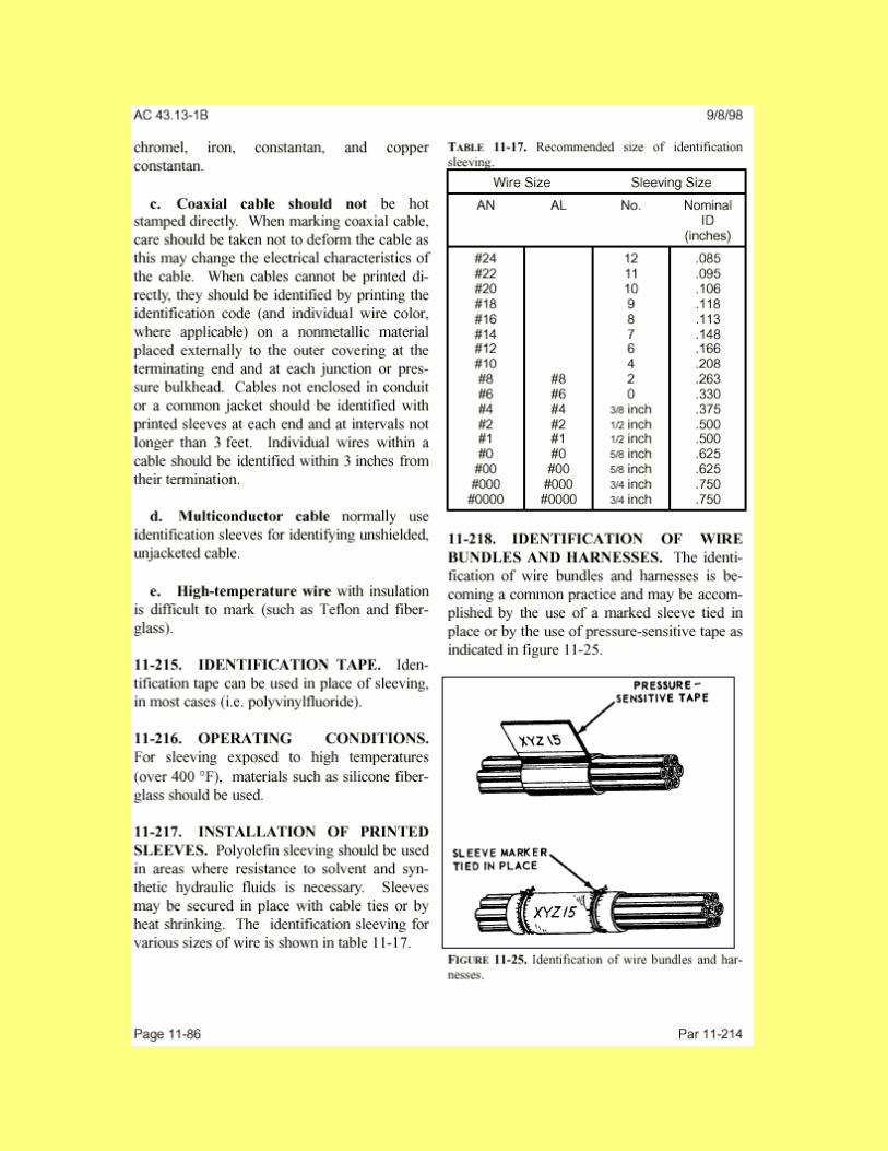
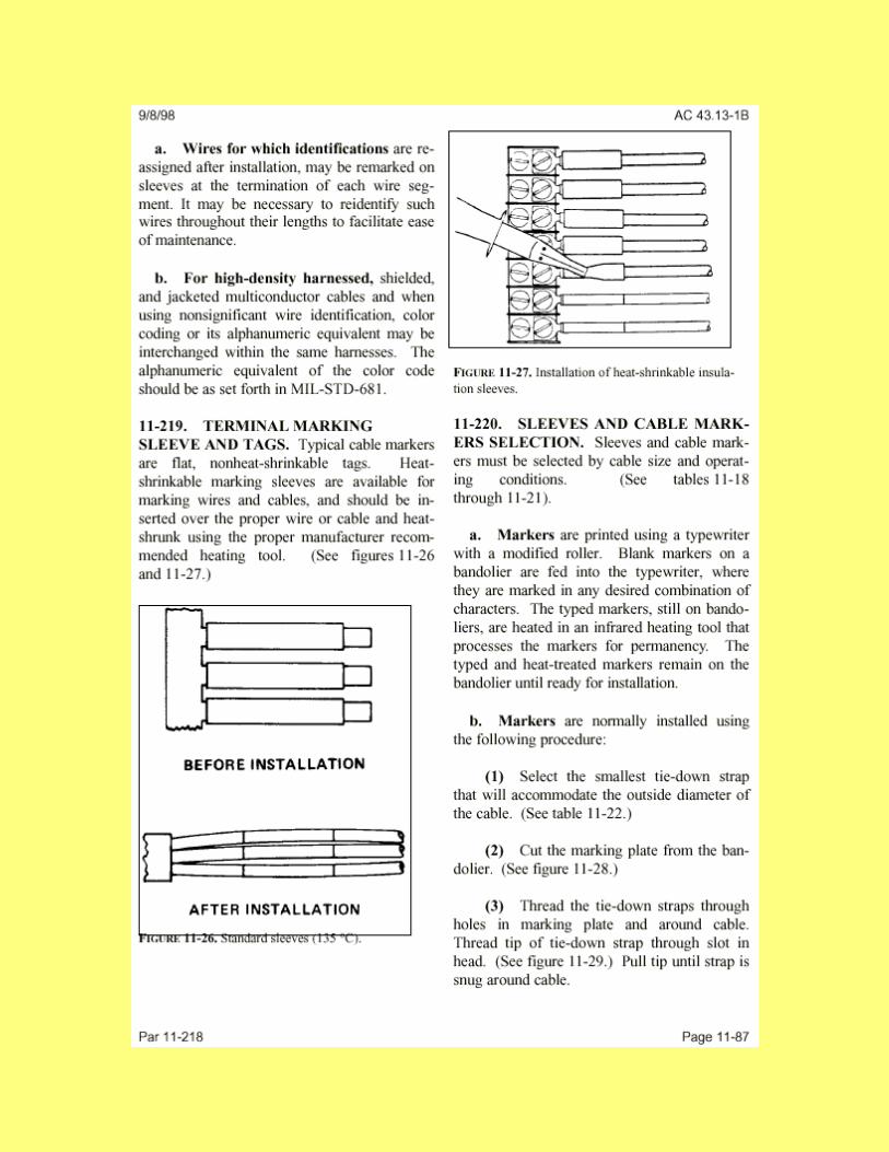
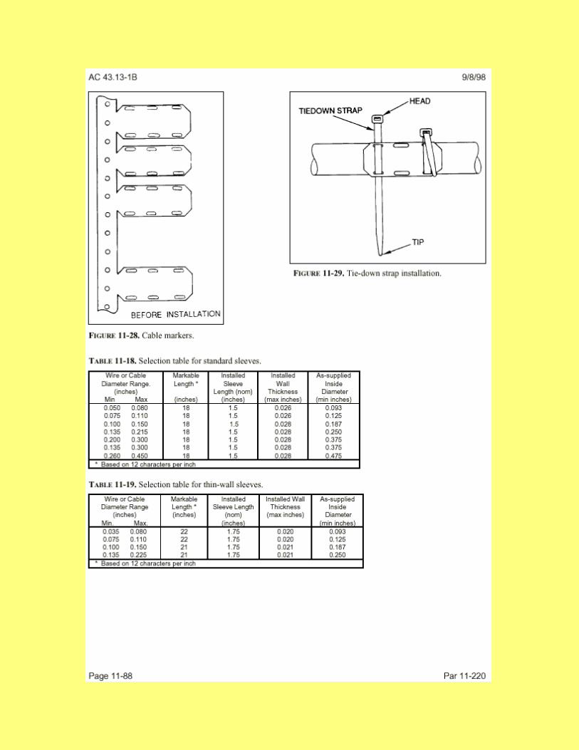
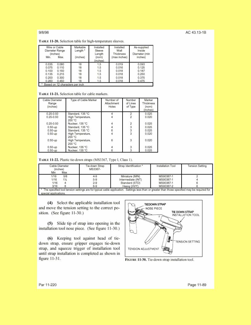
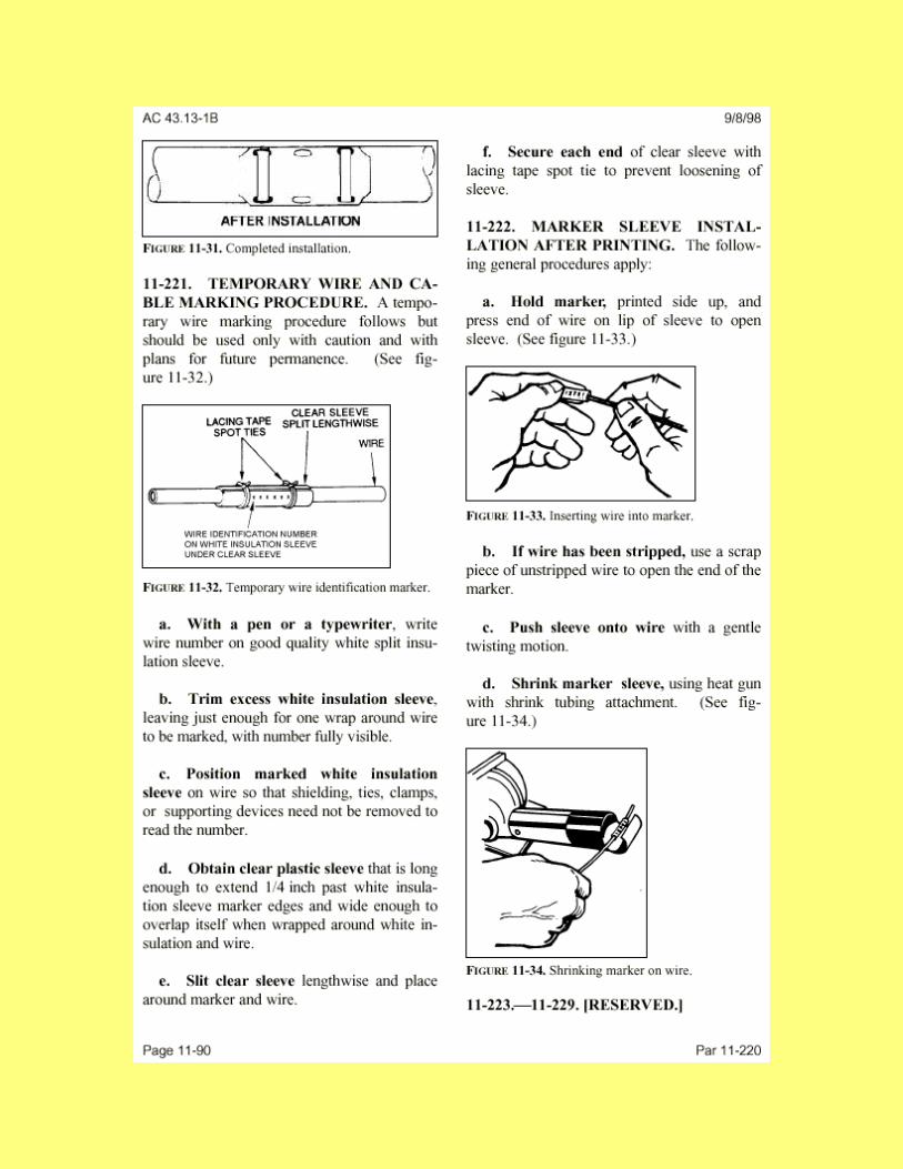
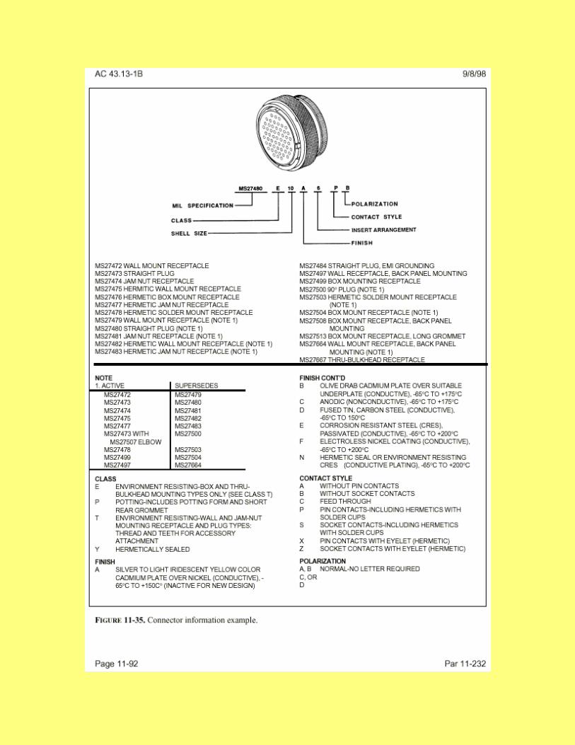
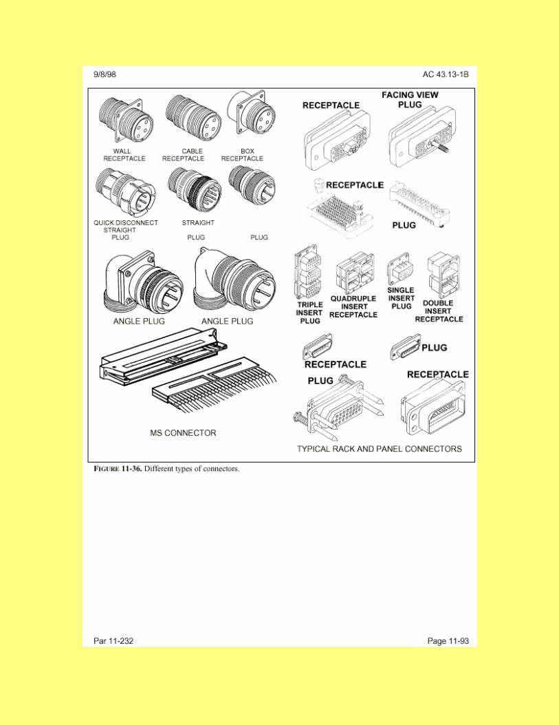
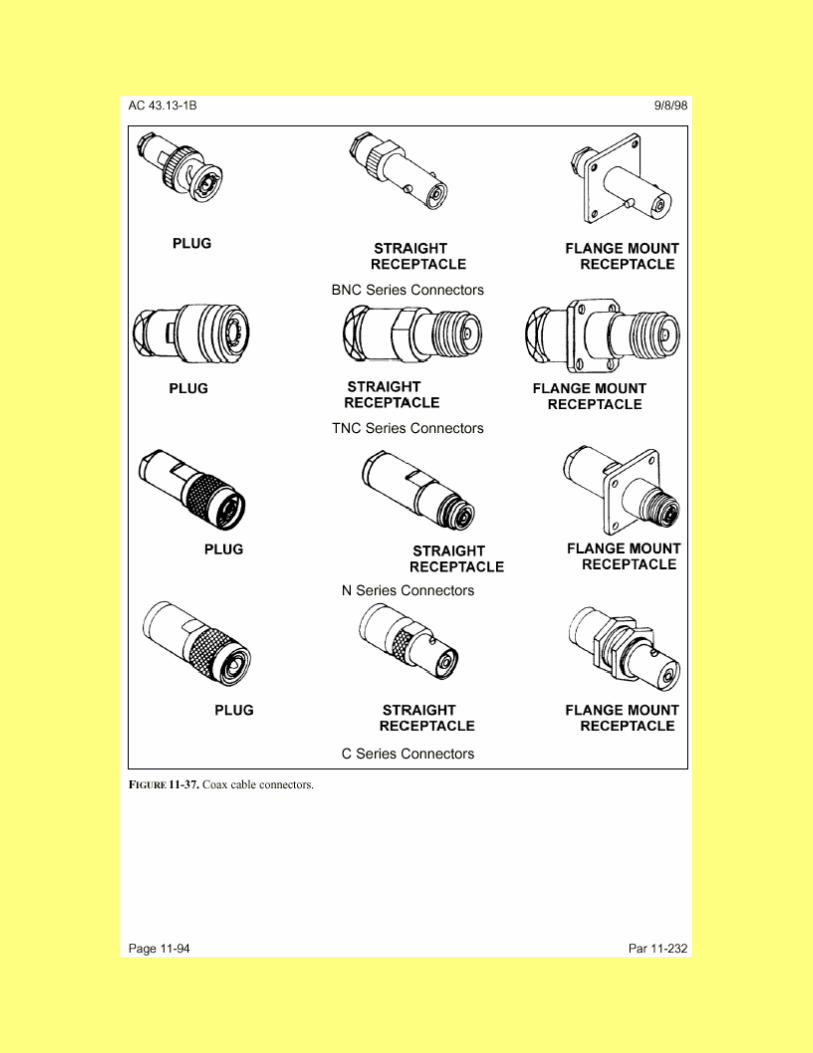
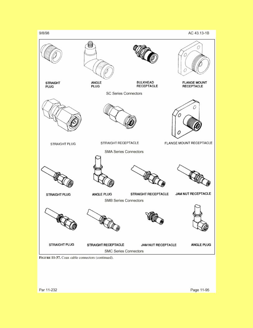

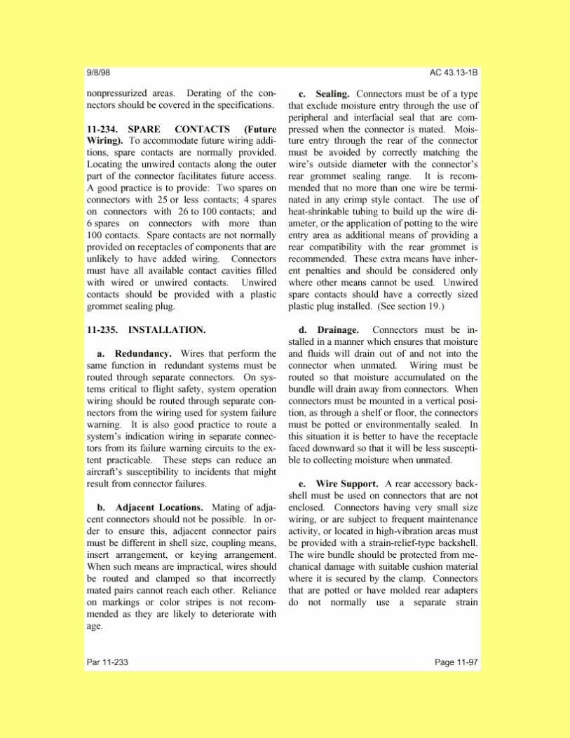

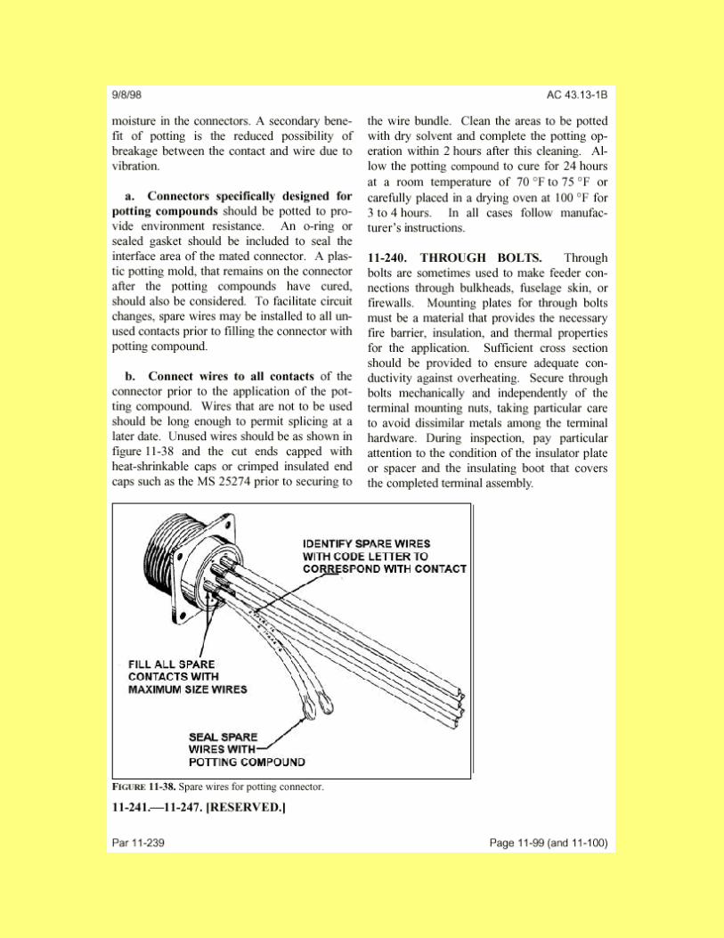
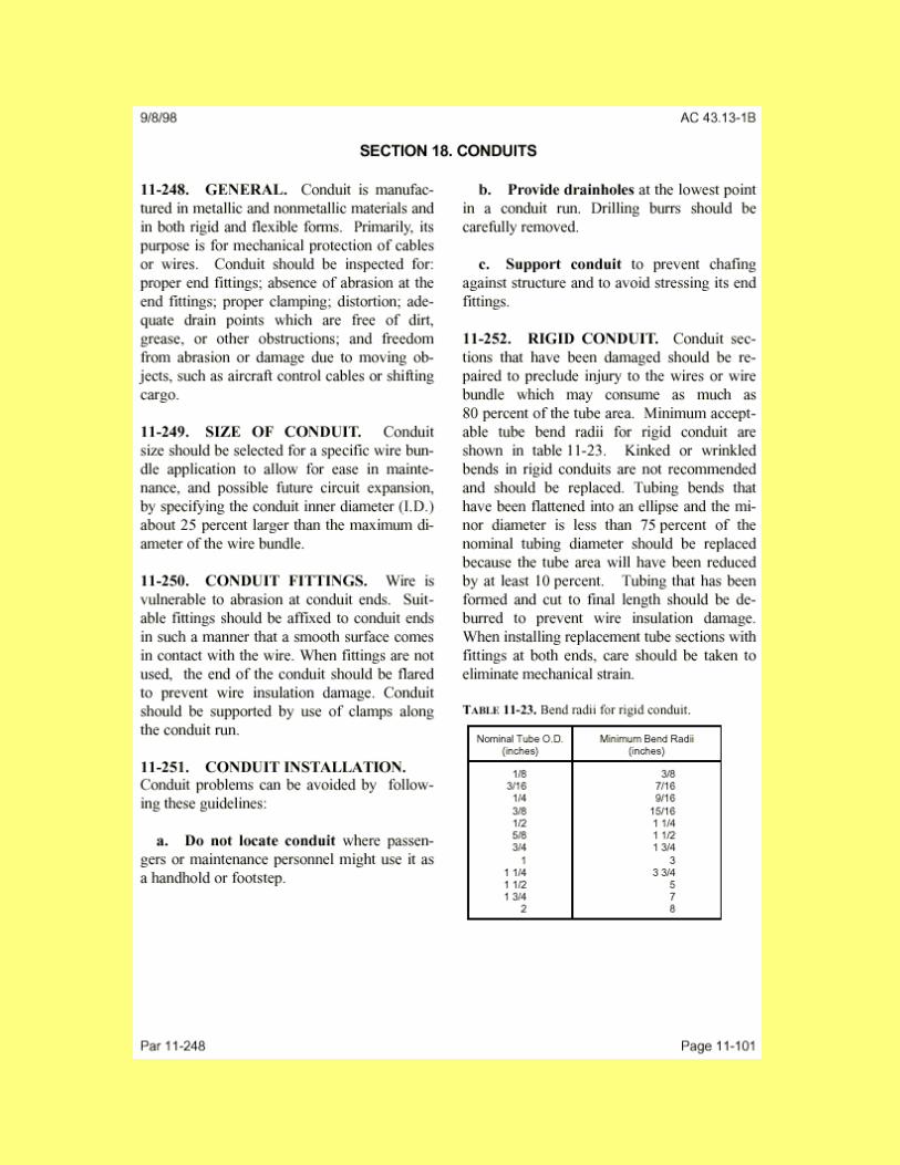
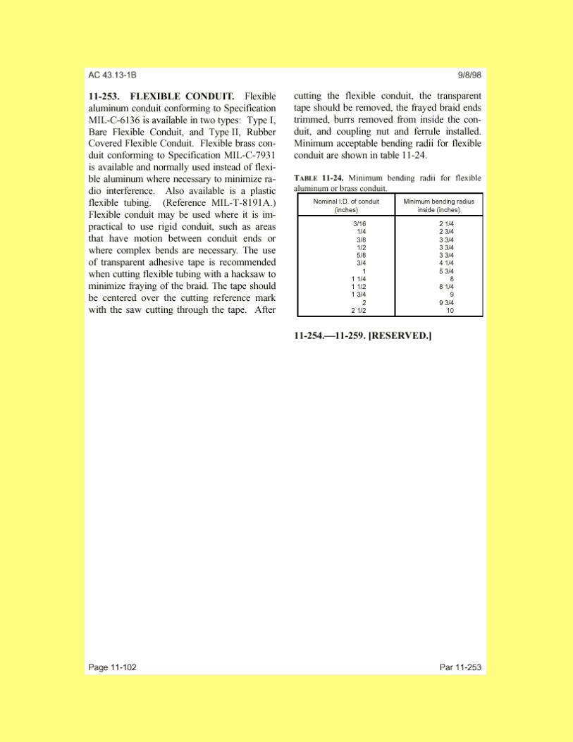
appendix A 523-0776031
Revised 4 March 1998 A-85
Revised 4 March 1998
appendix A 523-0776031
A-86

appendix A 523-0776031
Revised 4 March 1998 A-87
Revised 4 March 1998
appendix A 523-0776031
A-88
appendix A 523-0776031
Revised 4 March 1998 A-89
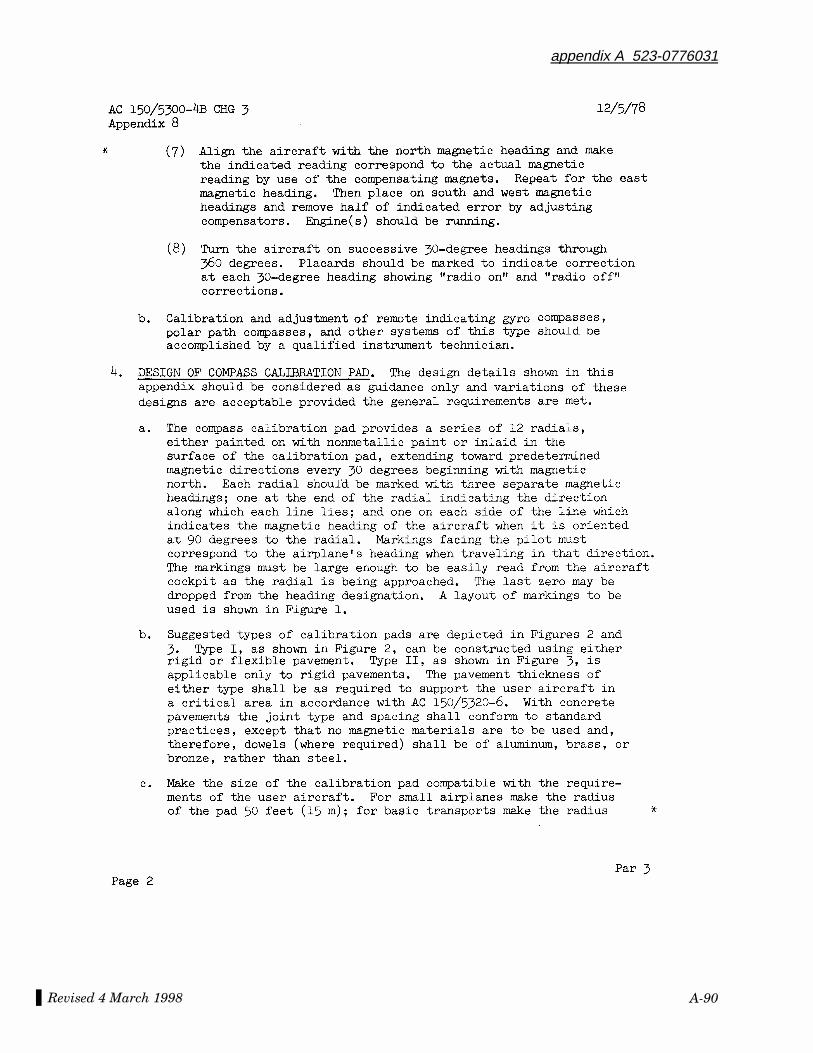
Revised 4 March 1998
appendix A 523-0776031
A-90
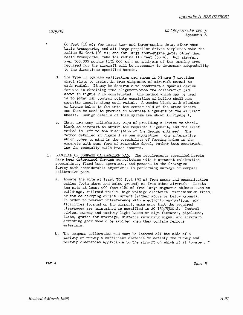
appendix A 523-0776031
Revised 4 March 1998 A-91
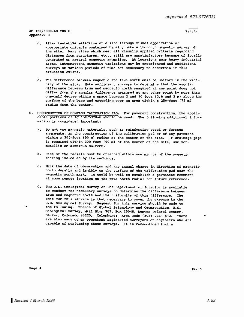
Revised 4 March 1998
appendix A 523-0776031
A-92
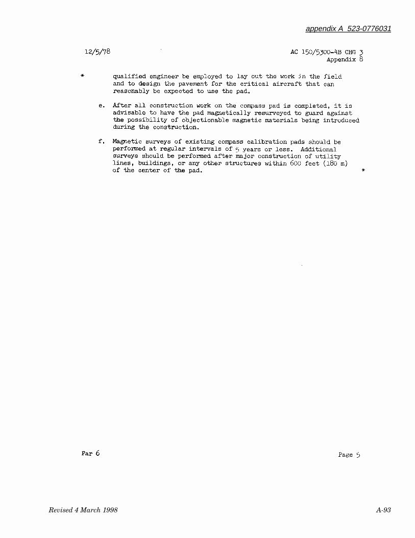
appendix A 523-0776031
Revised 4 March 1998 A-93
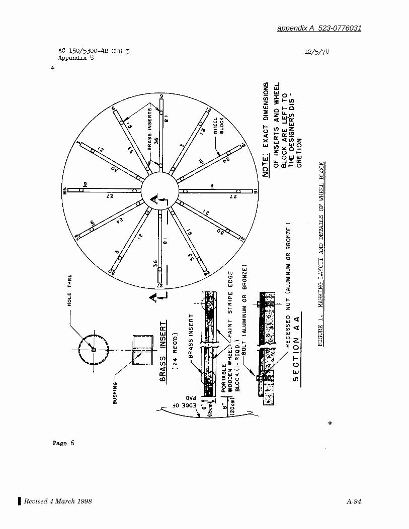
Revised 4 March 1998
appendix A 523-0776031
A-94
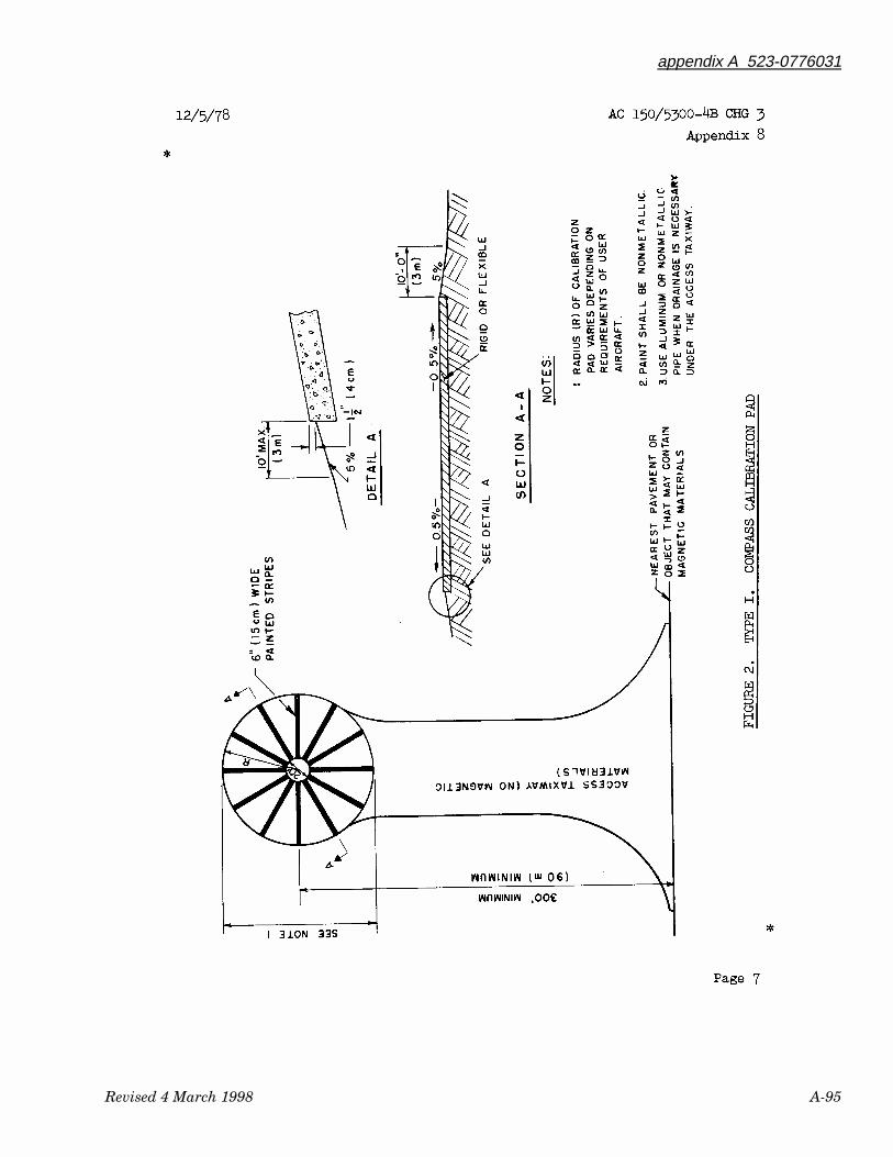
appendix A 523-0776031
Revised 4 March 1998 A-95
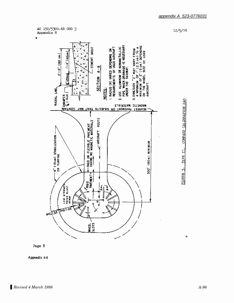
Revised 4 March 1998
appendix A 523-0776031
A-96