practical process control - personal webpages at...
TRANSCRIPT

Practical process controlExamples from a chemical industry
Krister Forsman
2017-11-08

Typical tasks for the control group
• Improve productivity by decreased variation and increased automation.
– Smarter control structures, e.g. feedforwards, mid-ranging, split range, cascades, maximizing control, ratio-in-cascade
– PID control parameter tuning
– Plant-wide control issues
– Introduce new controllers
– Support in design and commissioning of new plants
• Process historian (database) ownership; applications and development in Industrial ICT
• Training seminars

K. Forsman, 2017-11-08, No. 3
Tools are centered around Matlab
• The most important tools in the optimization work is Matlab and IP21.
• We have developed our own libraries for
– Data collection from IP21
– Data analysis
– Simulation of controllers and control structures
– Identification
– Assessment of control performance
• Some examples of tools below


K. Forsman, 2017-11-08, No. 5
Process model structures supported by our Matlab library
sT
KesL
+
−
1KLT
Integrating( )sTs
eksL
v
+
−
1
IPZ( )
( )1
2
1
1
sTs
esTksL
v
+
+−
( )( )( )31
2
11
1
sTsT
esTKsL
++
+−
PPZ
( )31 sT
Ke sL
+
−
P3
~80% of all loops
~15% of all loops

K. Forsman, 2017-11-08, No. 6
Representation of control structures: PID (piping and instrumentation diagram ☺☺☺☺)
PC
v1 , q1 v2p q2
FC
Constantpressure = 1
Atmosphere
Simple example: gas pipe
FC = flow controller, PC = pressure controller, LC = level ctrl, TC=temperature ctrl
FT = flow transmitter, etc
Why not use block diagrams, as in most control textbooks?
PT FT

K. Forsman, 2017-11-08, No. 7
Block diagram for the same process
P1
P2
P3
v1q1
v2
q2
p-
C1
C2

K. Forsman, 2017-11-08, No. 8
Control optimizationA set of practical examples

K. Forsman, 2017-11-08, No. 9
Ex: Level control with improvement opportunity
• The level in the tank varies too much, because there are pressure variations in the line for the incoming flow.
• We can’t tune the controller more aggressively - then it becomes unstable.
• Can we still improve control performance?
LC
FT

K. Forsman, 2017-11-08, No. 10
Solution: Control the flow too!
= Cascade control
LC
FC
SP
PV

K. Forsman, 2017-11-08, No. 11
Cascade control block diagram
• Which disturbances motivate the use of cascade control?
C1 C2 P2 P1+
d1
r1 y1
u1 = r2 u2 y2
+
d2
+
d3
Answer: d1

K. Forsman, 2017-11-08, No. 12
CT
FT
Stock
Dilution water header
Consumers
Example: Dilution process
• Task: Control the concentration measured by the transmitter CT, by manipulating dilution water valve FV.
• How would you do that?
FV

K. Forsman, 2017-11-08, No. 13
CC
CT
FC
FT
FC.sp = CC.op
Stock
Dilution water header
Consumers
Structure for concentration control
• Concentration (consistency) control in cascade against dilution water flow.
• Scenario: There is a pressure drop in the dilution water header, because one of the other consumers suddenly increases its demand.
• We will now see how the cascade controller reacts to this, depending on the tuning of master and slave controller.

0 20 40 60 80 100 120 140 160 180
4.8
5
5.2
5.4
5.6
5.8
0 20 40 60 80 100 120 140 160 18045
46
47
48
49
50
51
52
0 20 40 60 80 100 120 140 160 180
50
52
54
56
58
60
62
y1
r1
y2
r2
u2
Master SP and PV
Slave SP and PV
Valve
Slave controllermuch fasterthan master.
Rule of thumb forcascade control
to work:Time constantin slave 10
times faster thanin master.
The disturbanceis handled by
the slave controllerbefore the mastercontroller reacts(in principle).

0 20 40 60 80 100 120 140 160 180
50
52
54
56
58
60
62
0 20 40 60 80 100 120 140 160 18045
46
47
48
49
50
51
52
0 20 40 60 80 100 120 140 160 180
4.8
5
5.2
5.4
5.6
5.8
y1
r1
y2
r2
u2
Master SP and PV
Slave SP and PV
Valve
Difference betweenslave and mastersmaller than inprevious slide.
The disturbanceis handled by
the slave controllerbut the master
controller also reacts,later on.

0 50 100 150 200 250 300 350
50
55
60
65
0 50 100 150 200 250 300 35040
45
50
55
60
65
0 50 100 150 200 250 300 3503
4
5
6
7
y1
r1
y2
r2
u2
Master SP and PV
Slave SP and PV
Valve
Master and slavecontroller almostequally fast.
The disturbanceis thrown
back and forthbetween master
and slave.
Almost unstable.

K. Forsman, 2017-11-08, No. 17
New case
K. Forsman, 2017-11-08, No. 18
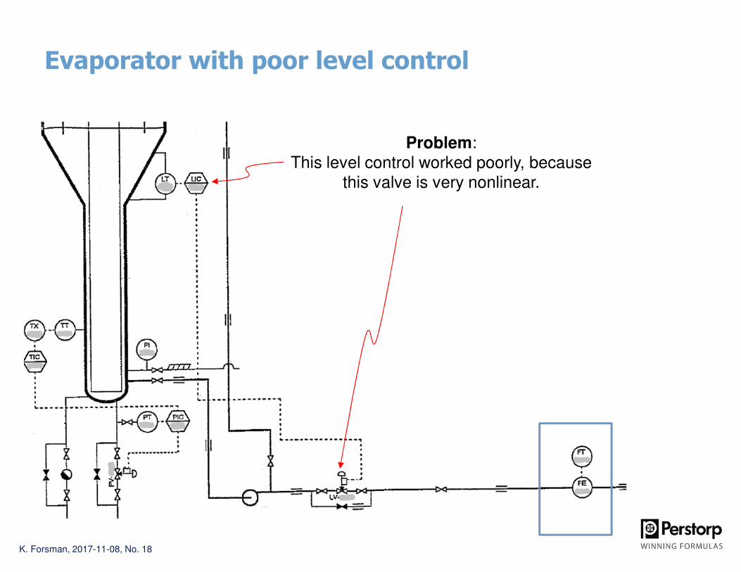
Evaporator with poor level control
Problem:This level control worked poorly, because
this valve is very nonlinear.

K. Forsman, 2017-11-08, No. 19
Solution:Manipulate the flow incascade against level,using the flow meter.

More stable level and smoother flow using cascade control
LC
.PV
FI.
PV
LC
.OP
LC
.PV
FC
.PV
FC
.OP
In this case, cascade control is used to linearize the slave process,rather than for disturbance rejection.

K. Forsman, 2017-11-08, No. 21
Ex: Level control with improvement opportunity
• The level in the tank varies too much because of variations in output flow.
• We can’t tune the controller more aggressively - then it becomes unstable.
• Can we still improve control performance?
LC
FT

K. Forsman, 2017-11-08, No. 22
Feedforward: Give early information to the controller
( ) ( ) FF
t
i
c ueT
teKtu +
+= ∫
0
1
Feedback term Feedforward term
LC
FT
+
KFF
FF

Density control in a dissolver
Dissolver
Centrifuge 1 Centrifuge 2
FT20
FC19
FC21
FC22
Issue: Sometimes one of the flows FC-19 or
FC-21 is closed for cleaning the centrifuge.
Then there will be a large deviation in density
in the dissolver.
solids
solidsmother liquor mother liquor
This controller is the mostimportant one!
DC24
FF
+
water
SP

K. Forsman, 2017-11-08, No. 24
Dissolver: FF and PI tuning reduces variations
Feedforward, and some other improvements, introduced

K. Forsman, 2017-11-08, No. 25
New case

K. Forsman, 2017-11-08, No. 26
Evaporators: Ratio control issue
Raw material feed is master
Steam flow in ratio against feed
Process: Raise the concentration by boiling water away.

K. Forsman, 2017-11-08, No. 27
Traditional ratio control structure
C1 P1
r1
C2 P2
r2
α
12 yr α=
y1
y2
x

K. Forsman, 2017-11-08, No. 28
Disadvantage with this structure
Why do we gets humpsin concentration?
Feed; Setpoint
Concentration
Time [min]
K. Forsman, 2017-11-08, No. 29
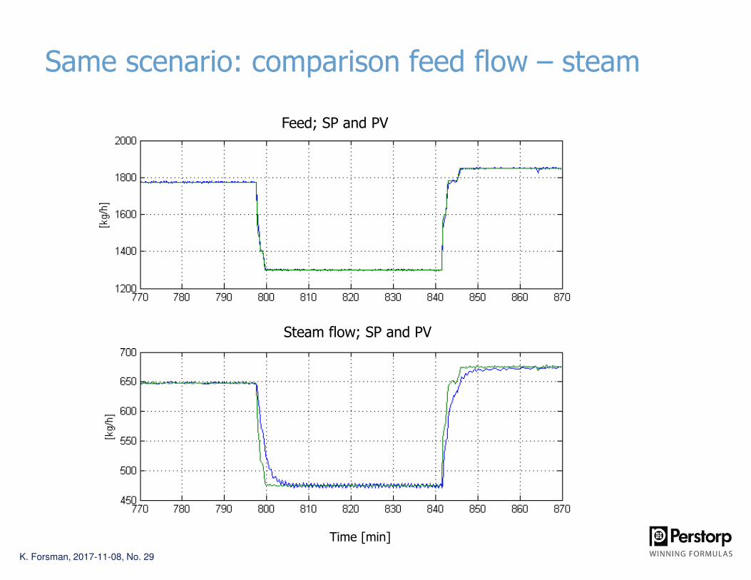
Same scenario: comparison feed flow – steam
Feed; SP and PV
Steam flow; SP and PV
Time [min]

K. Forsman, 2017-11-08, No. 30
The ratio steam / feed not constant during SP-changes
What should we doin order to reduce
the deviation in ratio?
Ratio steam / feed
Time [min]

K. Forsman, 2017-11-08, No. 31
Speed up steam flow controller! Result:
Time [min]
Concentration
Feed; Setpoint
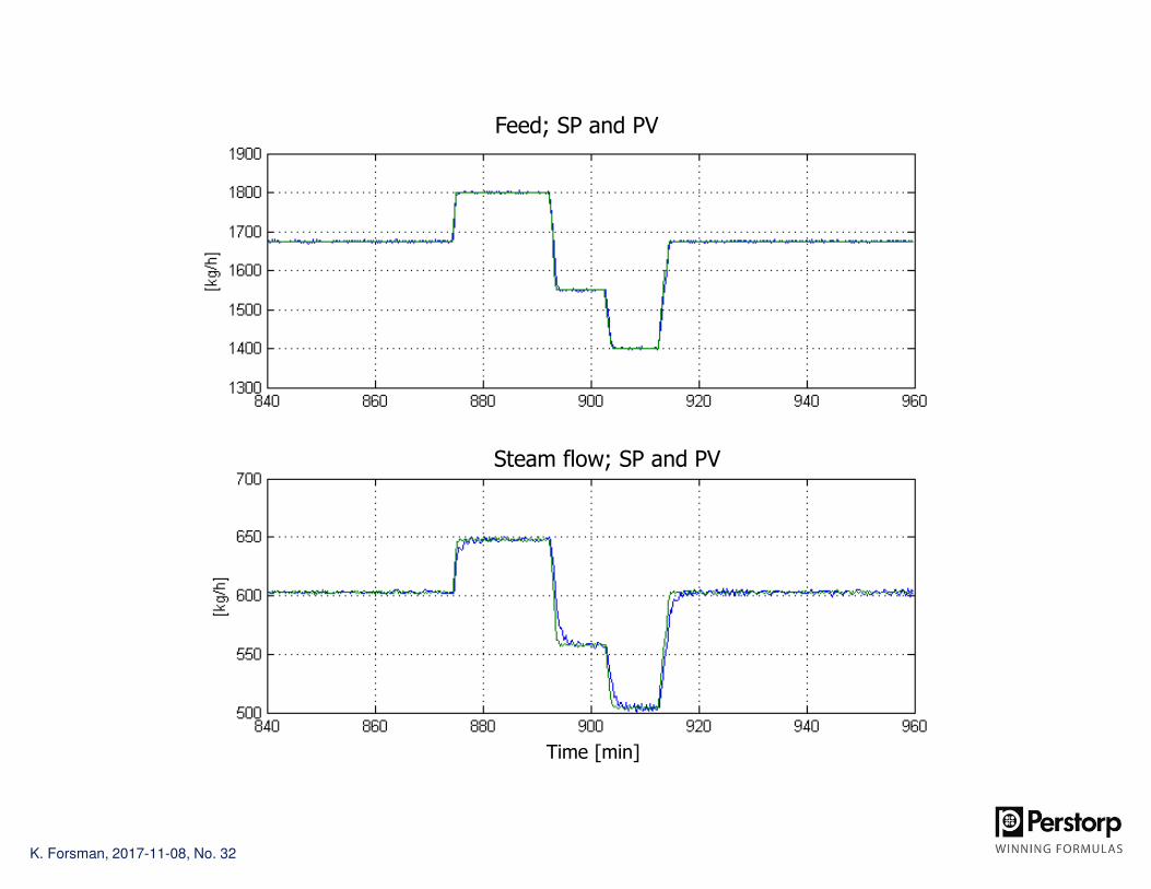
K. Forsman, 2017-11-08, No. 32
Feed; SP and PV
Steam flow; SP and PV
Time [min]
K. Forsman, 2017-11-08, No. 33
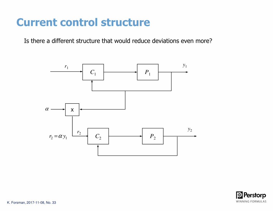
Current control structure
C1 P1
r1
C2 P2
r2
α
12 yr α=
y1
y2
x
Is there a different structure that would reduce deviations even more?
K. Forsman, 2017-11-08, No. 34
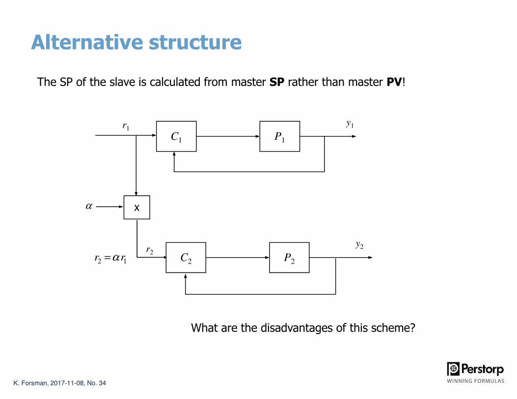
Alternative structure
12 rr α=
C1 P1
r1
C2 P2
r2
α
y1
y2
x
The SP of the slave is calculated from master SP rather than master PV!
What are the disadvantages of this scheme?

K. Forsman, 2017-11-08, No. 35
Test run: Ratio against SP
Feed; Setpoint
Concentration
Time [min]

K. Forsman, 2017-11-08, No. 36
New case

K. Forsman, 2017-11-08, No. 37
Reactor control; Residual oxygen
• Process: Two phase oxidation reactor (liquid-oxygen)
– On-line measurement of residual O2 in reactor gas; must be controlled.
– Which different control structures are feasible, and what are their respective advantages?
R-101
Liquid
Oxygen
FT101
AT101
FT102
LC
Liquid feed is master = TPM
(determines production rate)
Reactor gas
Product

K. Forsman, 2017-11-08, No. 38
Alternative 1: O2-feed in cascade against residual-O2
R-101
Liquid
Oxygen
FC102
Cascade control
FC101
AC101
K. Forsman, 2017-11-08, No. 39
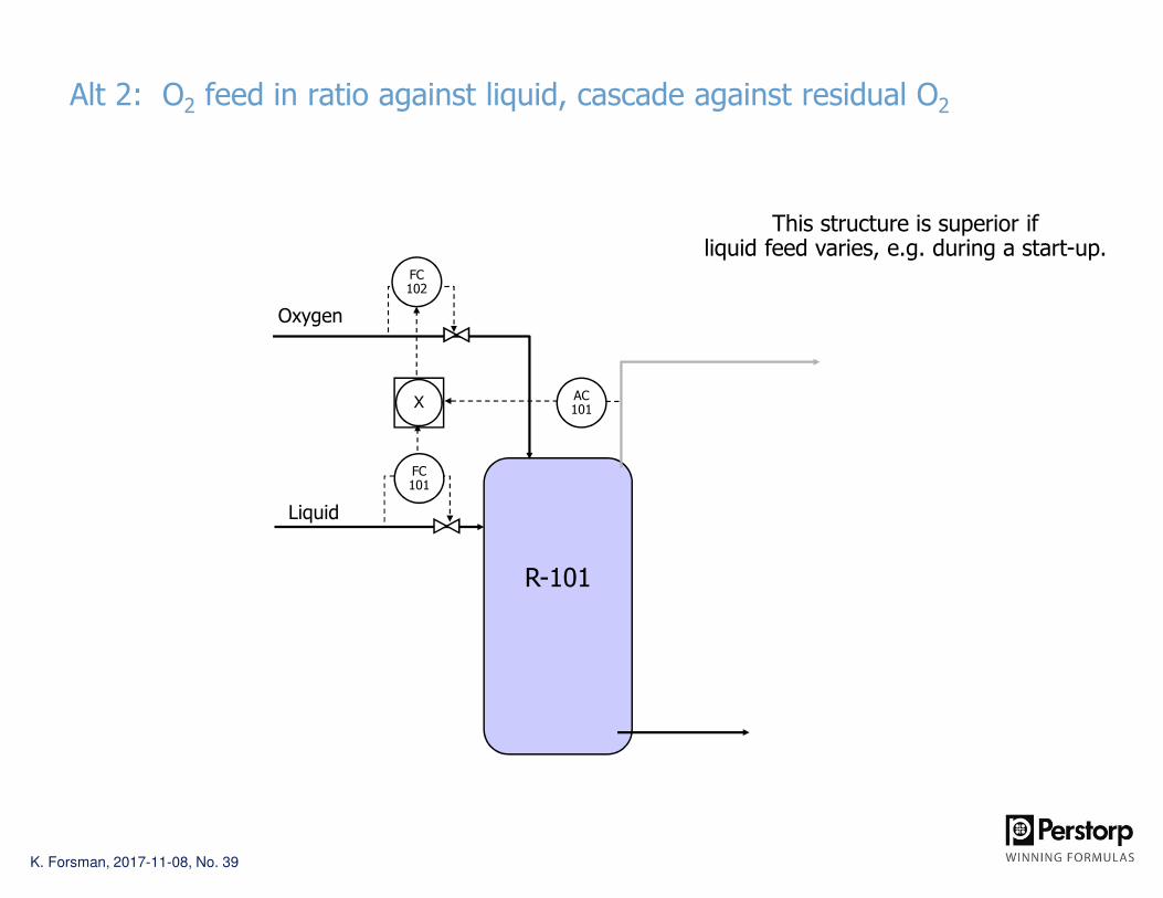
Alt 2: O2 feed in ratio against liquid, cascade against residual O2
R-101
Liquid
Oxygen
FC102
FC101
AC101X
This structure is superior ifliquid feed varies, e.g. during a start-up.

K. Forsman, 2017-11-08, No. 40
New case

Crystallizer: Level disturbance from wash sequence
• A crystallizer is automatically flushed with water, once every second hour. The water flow is large enough to affect level.
• It’s important to keep a steady level.
Flushwater
Crystallizer feed
Improvement suggestions?

K. Forsman, 2017-11-08, No. 42
Crystallizer: Feedforward reduces level variations
Flushwater
Crystallizer feed
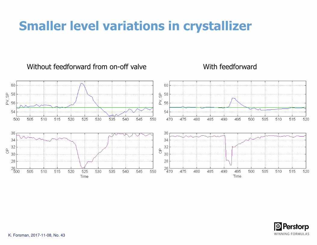
• A FF from on-off-valve to level controller reduces level variations.
• Thus, it’s ok to make a FF from a discrete (binary) variable.
+
K. Forsman, 2017-11-08, No. 43
Smaller level variations in crystallizer
Without feedforward from on-off valve With feedforward

K. Forsman, 2017-11-08, No. 44
Why don’t we do the full compensation?
There us a residual level disturbance,because the feedforward gain used wasonly 0.8 of that calculated theoretically.
Why didn’t we use the fullgain for compensating?

K. Forsman, 2017-11-08, No. 45
New case

K. Forsman, 2017-11-08, No. 46
Sewer pH-control process
pHT
NaOH
There are two valves for feeding caustic to the pit:a small, accurate one, and a larger coarse valve.
So we have one extra degree of freedom for controlling pH.How can we design a control scheme that utilizesthis freedom in a good way?

K. Forsman, 2017-11-08, No. 47
Solution: Mid-ranging (valve position control)
pHT
NaOH
pHC
VPCOP
PV
Let a pH-controller manipulate the small valve
Introduce a valve position controller (VPC) which controlsthe position of the small valve by slowly adjustingthe large valve (working through the process).

K. Forsman, 2017-11-08, No. 48
Block schedule for MR-control: Give setpoint for u1
C1
C2
r1 = SP for y
P2
+
P1
u1
u2
y
r2 = SP for u1
Fine valve
Coarse valve
VPC = valve position controller

K. Forsman, 2017-11-08, No. 49
pH control; Results
pH: Daily averages before and after new control structure

K. Forsman, 2017-11-08, No. 50
Improved pH-control gives fewer alarms
Before: 10 488 alarms in one month After: 418 alarms in one month
96% fewer alarms from this object.

K. Forsman, 2017-11-08, No. 51
New case

Exothermic reactor temperature control
TC
TT
Incomingcooling water
TT
FT
The reactor solution is circulated through a heat exchanger (cooler).The reaction is very exothermic: it is important to control the temperature.Typical variations/disturbances: Cooling water header pressure, CW temperature
HEX
Circulation loop

New control structure: Power control
TC
TT
TT
FT
DT X EC
SP
PV
Incomingcooling water
Power controller

K. Forsman, 2017-11-08, No. 54
HEX power control reduces variations between batches

K. Forsman, 2017-11-08, No. 55
New case

K. Forsman, 2017-11-08, No. 56
Mixingchest
QT
Dilution water header
Two step dilution: how to use the extra DoF?
This consistencyshould be controlled

K. Forsman, 2017-11-08, No. 57
Mixingchest
VPC
QC
Dilution water header
Two step dilution = Typical case for mid-ranging

K. Forsman, 2017-11-08, No. 58
0 10 20 30 40 50 603.7
3.8
3.9
4
4.1
4.2
4.3
4.4
4.5
4.6
4.7
Time [min]
0 10 20 30 40 50 603.7
3.8
3.9
4
4.1
4.2
4.3
4.4
4.5
4.6
4.7
Time [min]
Consi
sten
cy [
%]
Before
After
Consi
sten
cy [
%]

K. Forsman, 2017-11-08, No. 59
HD tower(~1000 – 2000 m3)
VPC
QC
Pulp from pulp mill
Low consistency
stock
Dilution water Dilution water
Another example from pulping: HD tower

K. Forsman, 2017-11-08, No. 60
New case

K. Forsman, 2017-11-08, No. 61
pHT
pH control
• The purpose of this process is to stabilize the pH in the solution coming out of the tank.
– Manipulate the caustic added to the feed line. Don’t care about the level.
– All variation comes from the pH of the feed solution
• Which pH-meter should be controlled in feedback?
• Is there a control structure better than just PID control?
NaOH
pHT

K. Forsman, 2017-11-08, No. 62
pHC
The worst solution
• The solution below will give the highest variations in pH out of the tank.
• Since the meter is far away from the MV the process has a long deadtime, so we have to tune the controller very defensively.
NaOH
pHT

K. Forsman, 2017-11-08, No. 63
pHT
Better
• This solution is much superior to the previous one. The controller can be tuned aggressively, since there is only a short delay.
• However, the final pH is not controlled here.
NaOH
pHC

K. Forsman, 2017-11-08, No. 64
pHC
Even better: Cascade control
• Can you argue why this solution is better than the first one (only local control)?
NaOH
pHC

K. Forsman, 2017-11-08, No. 65
Thank you!