practical aspects of thermo-couples p m v subbarao professor mechanical engineering department...
TRANSCRIPT
Practical Aspects of Thermo-couples
P M V SubbaraoProfessor
Mechanical Engineering Department
Correct Use of Themocouples ….

Standard Calibration Setup
Ice-point
The result of the calibration is a table of EMF versus T values. The integral is never directly evaluated. Instead a polynomial curve fit to the calibration data gives:
njnjjjj TbTbTbbTFE .....2
2100
j
t
T
T ABAB dTTE
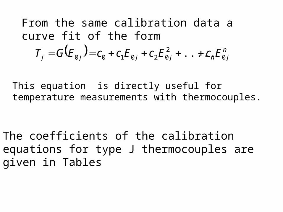
From the same calibration data a curve fit of the form
njnjjjj EcEcEccEGT 0
2020100 .....
This equation is directly useful for temperature measurements with thermocouples.
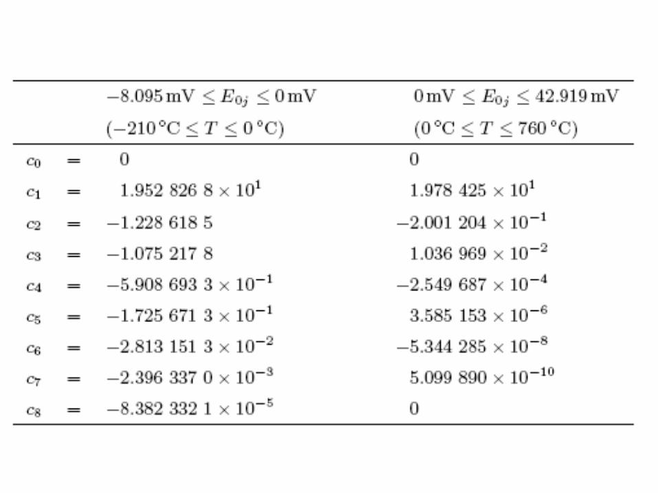
The coefficients of the calibration equations for type J thermocouples are given in Tables


Practical Thermocouple Circuits
• The equations given below are now applied to develop thermocouple circuits that can be used in a laboratory.
• The following ideas are important.• Compensation with a reference junction in an ice bath;• Compensation with a reference junction at an arbitrary
temperature;• Use of zone boxes for large numbers of thermocouples.
njnjjjj EcEcEccEGT 0
2020100 .....
njnjjjj TbTbTbbTFE .....2
2100
Practical Precautions
• The polynomial curve fit relies upon the thermocouple wire being perfect.
• It must not become decalibrated during the act of making a temperature measurement.
• Most measurement errors may be traced to one of these seven primary sources:

Primary Sources of Errors
1. Poor junction connection
2. Decalibration of thermocouple wire
3. Shunt impedance and galvanic action
4. Thermal shunting
5. Noise and leakage currents
6. Thermocouple specifications
7. Documentation

Poor junction connection
• To reach a higher measurement temperature, the joint must be welded.
• But welding is not a process to be taken lightly.
• Overheating can degrade the wire.
• The welding gas and the atmosphere in which the wire is welded can both diffuse into the thermocouple metal, changing its characteristics.
• The difficulty is compounded by the very different nature of the two metals being joined.
• Commercial thermocouples are welded on expensive machinery using a capacitive-discharge technique to insure uniformity.
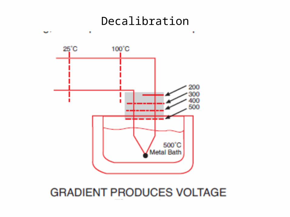
Decalibration
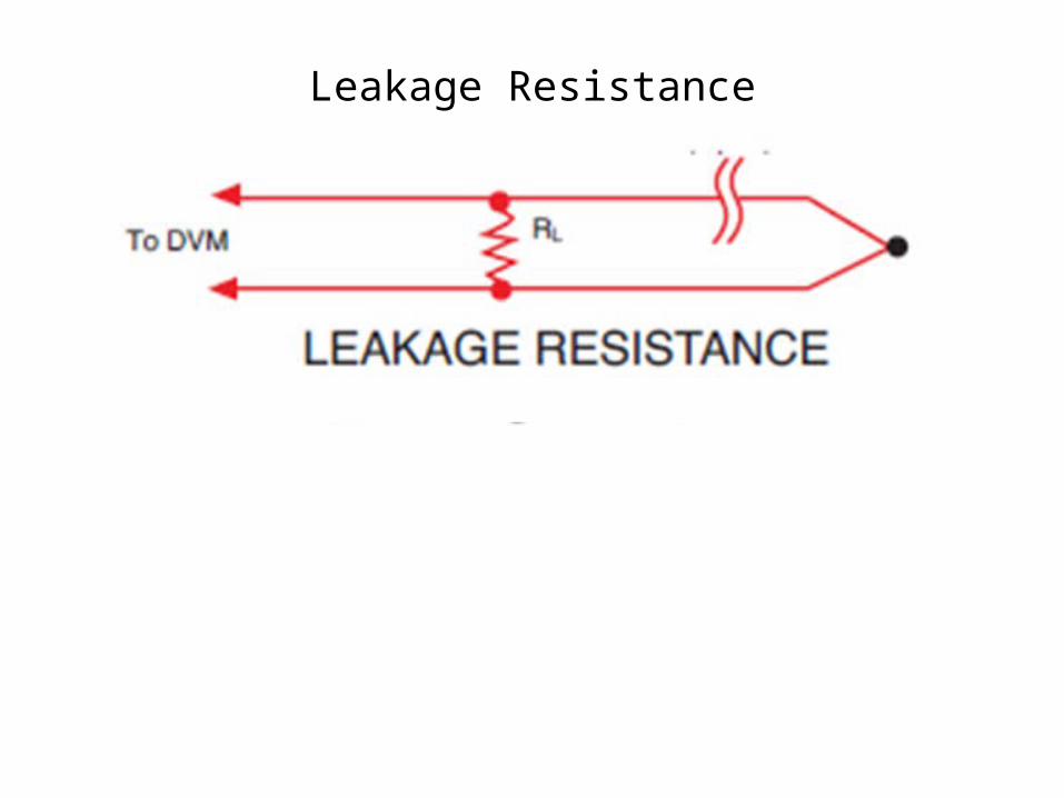
Leakage Resistance

Laws of Thermocouples
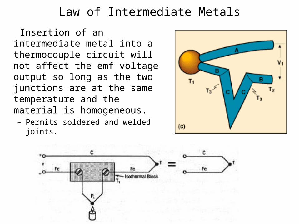
Law of Intermediate Metals
Insertion of an intermediate metal into a thermocouple circuit will not affect the emf voltage output so long as the two junctions are at the same temperature and the material is homogeneous. – Permits soldered and welded joints.
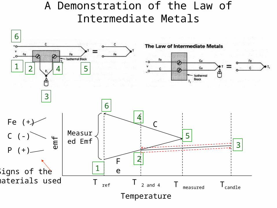
A Demonstration of the Law of Intermediate Metals
3
1 2 54
6
emf
Temperature
T ref T 2 and 4
Measured Emf
Fe
CFe (+)
C (-)
P (+)
Tcandle
12
T measured
35
4
6
Signs of the materials used
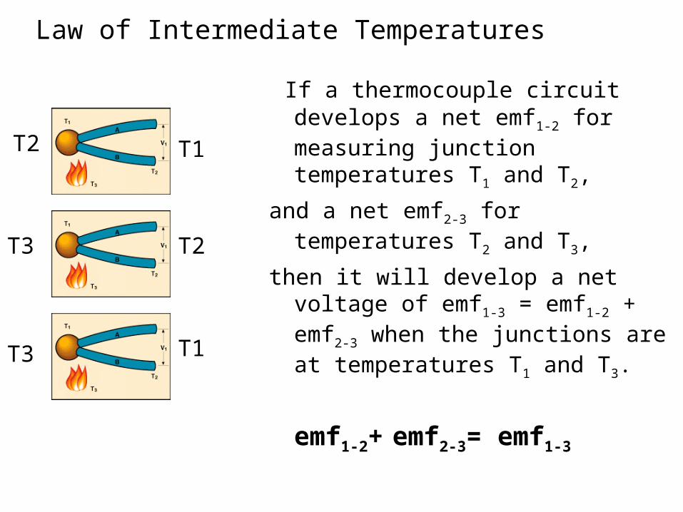
Law of Intermediate Temperatures
If a thermocouple circuit develops a net emf1-2 for measuring junction temperatures T1 and T2,
and a net emf2-3 for temperatures T2 and T3,
then it will develop a net voltage of emf1-3 = emf1-2 + emf2-3 when the junctions are at temperatures T1 and T3.
emf1-2+ emf2-3= emf1-3T3 T1
T3 T2
T2 T1
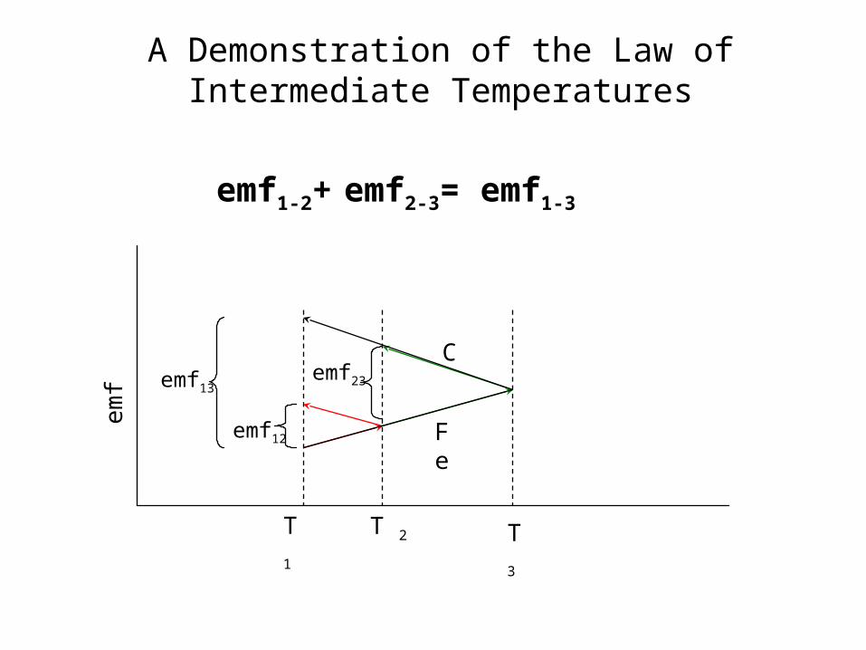
A Demonstration of the Law of Intermediate Temperatures
emf
T 1 T 2
Fe
C
T 3
emf23
emf1-2+ emf2-3= emf1-3
emf13
emf12
The integrity of a thermocouple system
• The integrity of a thermocouple system can be improved by following these precautions:
• Use the largest wire possible that will not shunt heat away from the measurement area.
• If small wire is required, use it only in the region of the measurement and use extension wire for the region with no temperature gradient.
• Avoid mechanical stress and vibration which could strain the wires.
• When using long thermocouple wires, connect the wire shield to the dvm guard terminal and use twisted pair extension wire.
• Avoid steep temperature gradients.
• Try to use the thermocouple wire well within its temperature rating.
• Use a guarded integrating A/D converter.
• Use the proper sheathing material in hostile environments to protect the thermocouple wire.
• Use extension wire only at low temperatures and only in regions of small gradients.
• Keep an event log and a continuous record of thermocouple resistance.
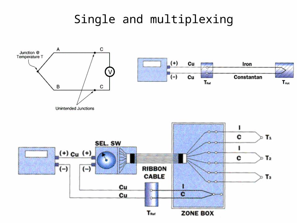
Single and multiplexing

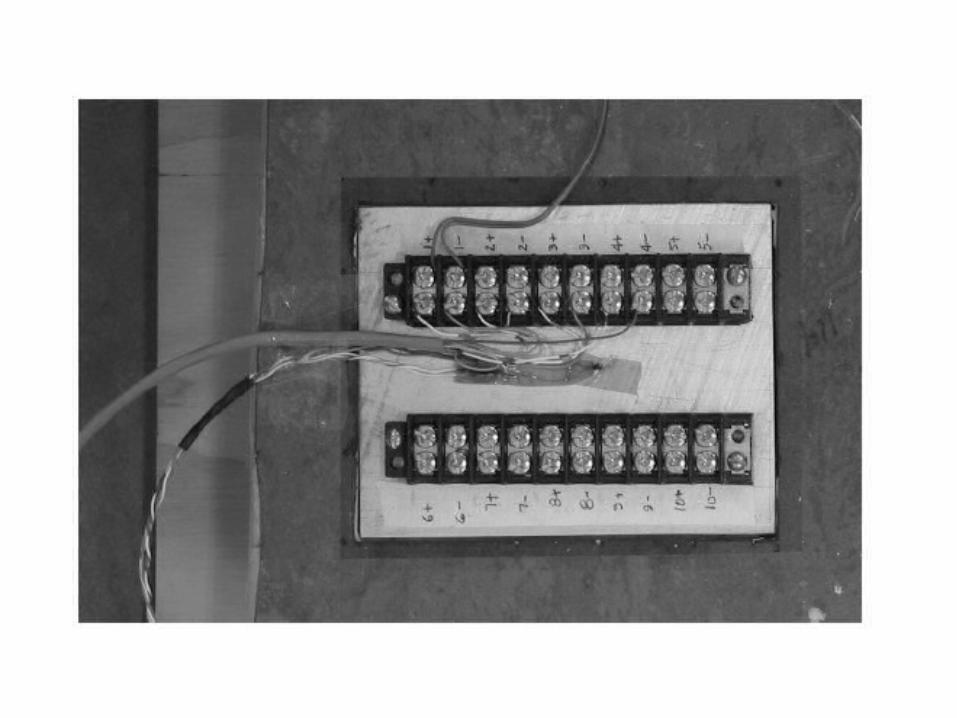
Use of a Zone Box for Multiple Thermocouples

A zone box with a thermistor to measure Tr.
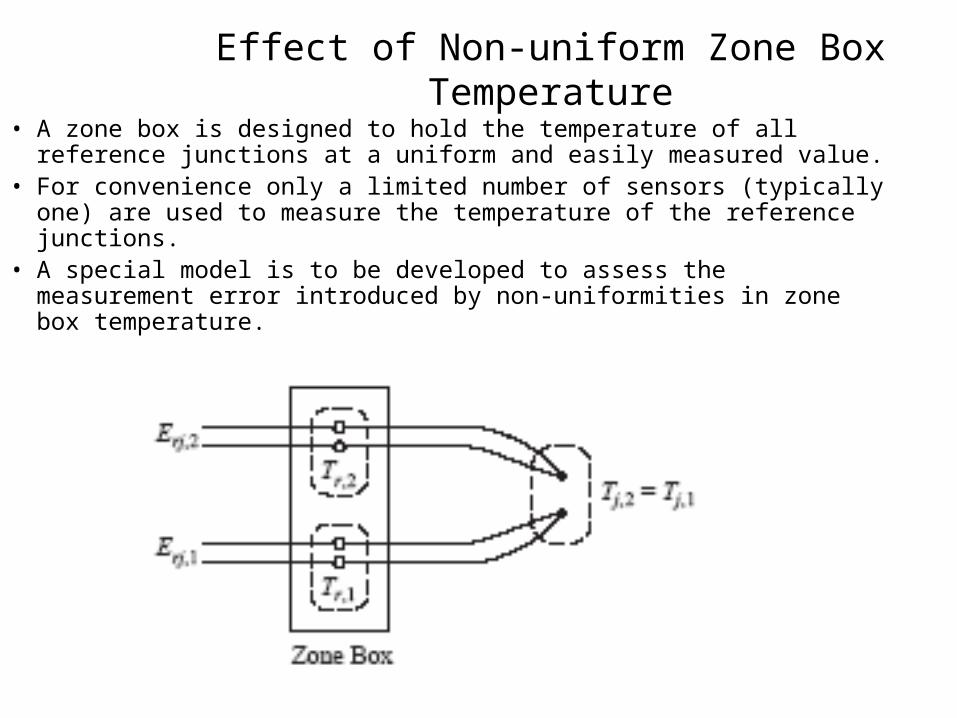
Effect of Non-uniform Zone Box Temperature
• A zone box is designed to hold the temperature of all reference junctions at a uniform and easily measured value.
• For convenience only a limited number of sensors (typically one) are used to measure the temperature of the reference junctions.
• A special model is to be developed to assess the measurement error introduced by non-uniformities in zone box temperature.
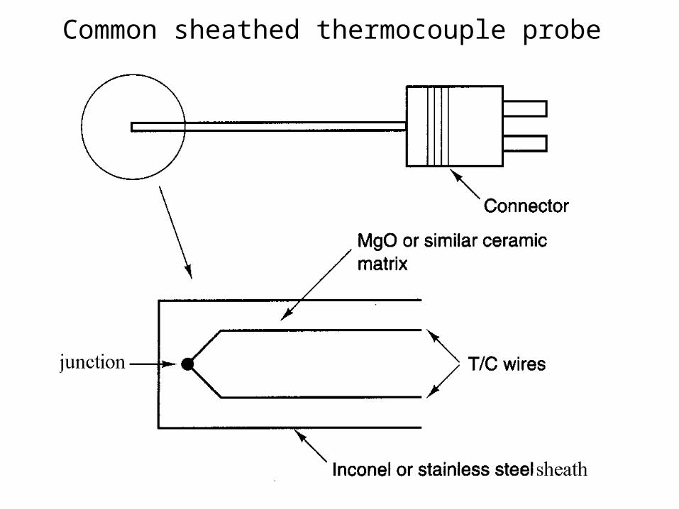
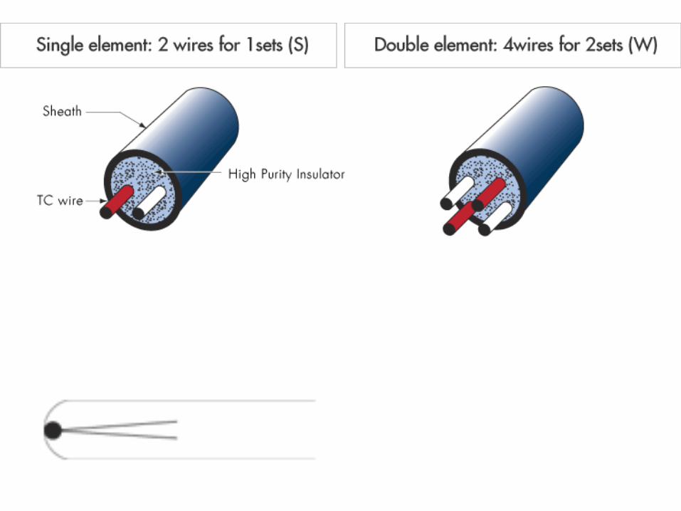
Common sheathed thermocouple probe

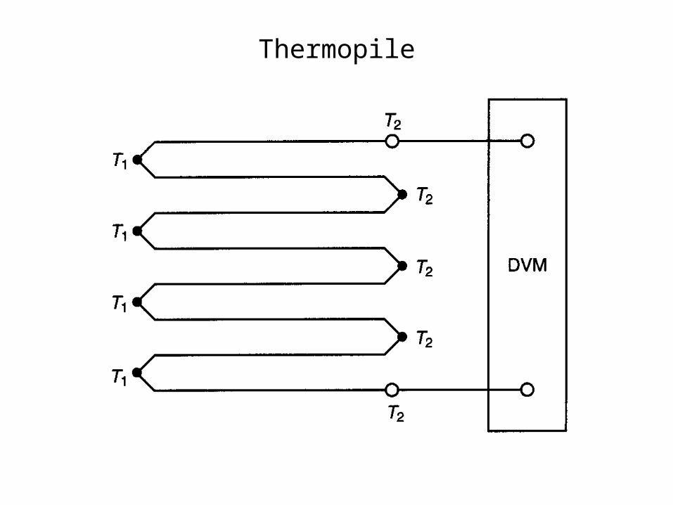
Thermopile
Temperature Measurement Errors
• Conduction
• Convection
• Radiation
• Response Time
• Noise
• Grounding issues and shorts, especially on metal surfaces