ppg wave 2 manual en - theppgs.comtheppgs.com/media/documentation/ppg_wave_2_manual_en.pdf ·...
TRANSCRIPT


INTRODUCTION
The PPG WAVE 2 is a polyphonic digital synthesizer that uses 8 independantly tuneable oscillators.Almost 2000 different waveforms are
di tally generated,64 in each of 32 wavetables.This unique feature allows nning through up to 64 waveforms in the course of a single event or note.Simple or complex waveforms can then be treated with envelope generators,filters and modulation oscillators before being
stored in the 100 programme capasity memory.Two dofferent programmes can be stored in each memory space,and this used with the split
keyboard and stereo output facility,allows for maximum versatility. The WAVE 2 do also contain an extremely flexible 8 track sequencer
including record update and a 10 fonction arpeggio programme.
G
\ \
.3
5

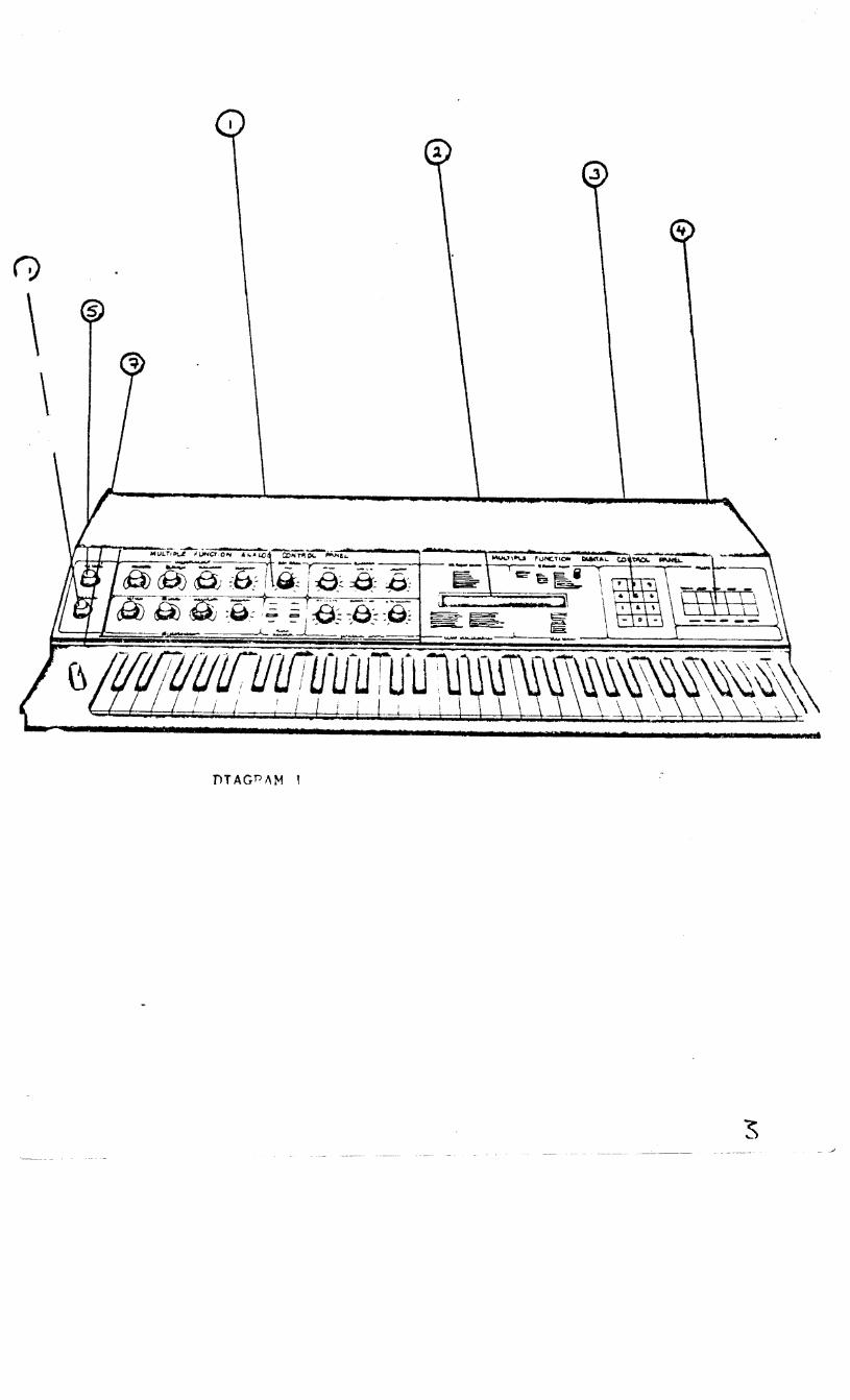
FRONT PANEL CONTROLS
1 ANALOGUE PANEL-controls all analogue functions 2 DISPLAY PANEL-80 character LCD display
SECTION 2
3 NUMERIC KEYPAD-used in various ways in conjunction with the display. 4 DIGITAL KEYPAD-far addressing all system function 5 MASTER TUNING-ta simultaneously tune all oscillators 6 MASTER VOLUME-output volume 7 PITCH WHEEL-spring loaded pitch control
4


ANALOGUE PANEL 1
1 ADSR 1---Attack:0-15 seconds
2 LFO RATE
Decay :0-30 seconds Sustain:sustain level(not length) Release:0-30 seconds
3 FILT~R cut off emphasis
4 PLlN Partial wave numbers 5 ADSR 2---Similar to ADSR 1 6 GROUP INDICATOR LEDs. In conjunction with the GROUP button on the digital panel, these indicate which group are being·addr~ss~d~- A,B or A & B. 7 ~ANEL INDICATOR LEDs. In conjunction with the PANEL button on the digital panel, these indicate which analogue panel is selected. 8 ENVELOPE 1 - VCF. Amount of ADSR 1 CV on filter. 9 ENVELOPE 2 - LOUD •. Amount of ADSR 2 CV on VCA. 10 ENVELOPE 1 - LlAVES. Amount of AOSR 1 CV on PLlN
6

",--,, ...

ANALOGUE PANEL 2
1 LFO. Delay: Introduces a delay before LFO has effect. Waveshape: Continuosly variable through triangle ramp, reverse
ramp and square waves. MOD INT: Output level of LFO.
2 ENV 3 This is an AR envelope only. Attack Release and output level controlling pitch.
3 PANEL INDICATOR LEDs. Second panel indicator will be lit.
4 ALL REMAINING CONTROLS HAVE THE SAME FUNCTION AS IN ANALOGUE PANEL 1 •
8

DIAGRAM q

ANALO~u( FANEL 3
1 8 StOUENCER OUTPUTS. The funclions of these oulPuls are assisned when in the seauence ~ode as explained in section
2 SEQU. This controls lhe •aster clocK rate for the seauencer.
3 PANEL INDICATOR LEDs. Third ~anel indicalor will be lit.
4 ALL REMAINING CONTROLS HAVE THE SAHE FUNCTIONS AS IN ANALOGUE PANEL 1

it
DIGITAL. PANEL
1 LCD DISPLAY.
2 LCD DISPLAY BRIGHTNESS CONTROL.
3 PROGRAMMING CODES.For use with disPla~.
4 NUMERIC KEYPAD. Disits O - 9 tosether with left and risht arrows for cursor 11ovenien t.
5 PROGRAMME BUTTON. This button will alwa~s move the cursor to the prosrarurue Point of the disPlaw. To chanse a Prosrarume use this button tosether with the desired Prosramme nuaber.
6 DIGITAL. This will chanse the disPla~ to the disital disPla~ in order to alter routing and control functions.
7 TUNING. This will chanse the disPla~ to the tunins disPla~ in order to checK individual tunins of oscillators.
8 ANALOGUE B~ usins this button the disPla~ will indicate the seitinss of all the controls on the analosue ~anel on a scale of 0 - 63. If another Panel is selected usins the Panel buttonr the disPlaY will automaticall~ chanse to that Panel.
9 SEQUENCE. This is used for seouence and arpessio functions. The cursor will aPPear under the seouence node headins.
10 GROUP. This button is ~sed to chanse the srouP. An~ control chaoses ~ade will onlw affect the srouP in use.The srouP LEDs on the analosue Panel indicate the state selected b~ this button.
11 DATAT. Use Lhis button to return to the ~ain disPlaw where the cursor will be under the data transfer column. This button is also used t.o transfer dala from one srouP to anolher' or from one Pro!1ra1111e to another.
12 KEYBOARD. This button can also be used to reLurn Lo Lhe main disPlaw and the cursor will aPPear under lhe Kewboard column. The Kewboard ~odes can be chansed usins this button as explained in sec lion
13 PANEL. This is used to chanse the analosue control Panel bet.ween its three modes and is indicated bw the Panel indicator LEDs.
14 RUN/STOP. This can be used to obtain the seauence disPla~ where the cursor will aPPear under Lhe RUN/ST headins. If in the main disPlaY t.his button will 111ove the butt.on to RUN/ST in that disPlaY•

MAIN DISF'L.AY
PROG:oo WAVElADLE:OO DATATRANSF:O KEYB:O "t:~u:oo 1:<UN/ST:o SPLIT:<><> CA~>:o TEs1·:0-o
DTAGDAll-1 6
-· 4 •
MAIN DISPLAY
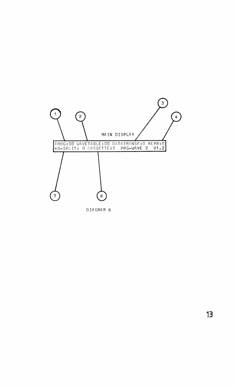
PROG:OO WAVETABLE:DD DATATRANSF:O KEYB:D KB-SPLIT: 0 CASSETTE:D PPG-WAVE 2 V1.2
DIAGRAM 6
13
3,1,7 SPLIT.Indicates the point at which the keyboard is split using Keyboard modes 4-8. The keyboard can be split at any point and the number entered here corresponds to the number of semitones from the left hand end of the keyboard. 3,1,8 CASSETTE.Indicates the state of the cassette interface.
0 no function. 1 load from cassette into memory.Automatically checked if error
9 appears in cassette column. 2 programmes loaded to cassette. 3 = sequences loaded to cassette. 4 = run loaded sequences with this command to check recording. If
error occured 9 appears in cassette column.
1 5
VJ:G:CTAL ItJ:E>F'l.AY
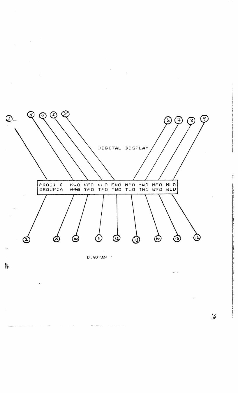
PF<OG: 0 l'\WO KFO r\LO ENCJ MPD MWO MFll MLO GROlff': A ~ reo TFO TWO TL.0 TMCJ WFO WL(J . I
IJ
DTAG'l"'.'AM 7
lG

3.2.DIGITAL DISPLAY
3.2.1 PROG Indicates selected prosra~•e. 3.2.2 GROUP As it is Possible to Prosramme different sounds into each srouP, two dis~laYs are necessar~ for each Prosram~e. The disPlaY for the other srouP is obtained usins the GROUP button on the disPlaw select Panel.
3.2.3 KW Keyboard voltase on Partial wave nu~bers.Ranse 0 = offr - 7 • ma>: i n1urn.
3.2.4 KF Keyboard voltase on the filter freouencY.Ranse 0 =off, - 7 -maximum.
3.2.5 KL Keyboard voltase on VCA.Ranse 0 = hish end loud, 4 = eoual balance• 7 = low end loud.
3.2.6 MP LFO on the Pitch.<vibrato>
3,2,7 MW LFO on partial wave nu~bers.
3.2.8 MF LFO on the filter frenuency.
3.2.9 ML LFO on the VCA.
NOTE: IN ALL LFO FUNCTIOS 0 = of fr 1 = on. THE INTENSITY IS COHTROLLEI• ON THE ANALOGUE PANEL.
J.2.10 TP Toucn sensitivit~ on Pitch. 0 - off, 1 = increase in Pitchr 2 = decrease in Pltch.
3.2.11 TF Touch sensitivit~ on filter. 0 = offr 1 = en.
3,2,12 TW Touch sensitivit~ on partial wave nurubers. 0 = off, 1 = on.
J,2.13 TL Touch sensitivity on loudness. 0 = off, 1 = on.
3.2.14 TM Touch sensitivit~ on LFO ~odulation intensitw. 0 = cffr 1 = on.
3.2.15 VF The velocity at which the Ke~board is strucK on filter. 0 = off' 1 = on. 3.2.16 The velocit~ at which the KeYboard is strucK on loudness.
I
I

TUN I NG It I t>F'L..AY
f'RDG; 0 0 MI CF~D 00 00 00 00 00 00 00 00 GROUP: A ~;EM l T 00 00 00 00 0() 00 00 00
J
DTAGPAM o
J~
ruNrr·
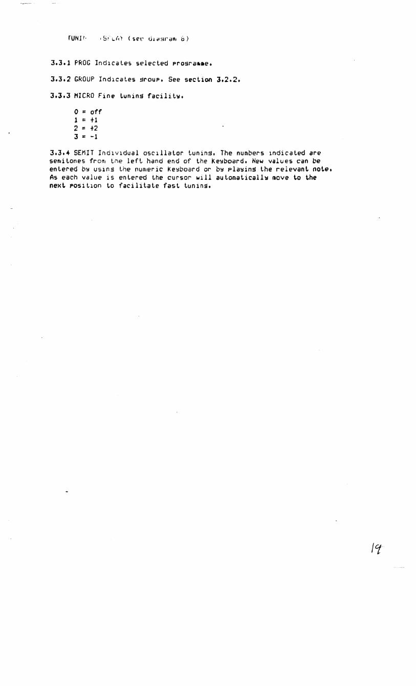
3.3.l PROG Ind1caLes selected Prosra•ae.
J.3.2 GROUP IndicaLes srouP. See section J.2.2.
J.J.J MICRO Fine tunins facilit~.
0 = off l = +1 2 = +2 3 = -1
3.3.4 SEMIT Individual oscillator tuning. The numbers indicated are semitones from Lne left hand end of the Ke~board. New values can be entered b~ us1ns Lhe nurueric Ke~board or b~ Pla~ins the relevant note. As each value is entered the cursor will automaticall~ ~ove Lo Lhe nexL position to facilitate fast tunins.

PROG:oo AOO DOO soo ROO ROO coo EOO POO Gr;;oue: A AOO [I()() ~)()0 ROO FOO LOO woo
I$"

3.4 ANALOGUE DISPLAY PANEL l (see diaS 9)
All values shown on this d1sPla~ are on a disit.al ranse of 0 - 63. An~ moveffient. of an analosue Panel control will result in a chanse of Lhe value in the relevant. disPlay coluffin. If Lhe orisinal values need Lo be seen asa1n aft.er chans1ns the controlsr simPl~ re-enter Lhe Prosra~me number. The laYouL of these values on Lhe disPlaw corresPond to Lhe analosue Panel la~ouL.
3.4.1 PROG Indicates selected Prosra~•e•
3.4.2 GROUP Indicates srou?.See section 3.2.2.
3.4.3 A = ATTACK envelope 1 16 slePs.
3.4.4 D - DECAY envelope l 32 steps.
3.4.5 S = SUSTAIN envelope l 64 steps.
J.4.6 R = RELEASE envelope l 32 slePs+
3.4.7 R = LFO RATE 32 stePS•
3.4.B C = FILTER CUTOFF FREJUENCY 64 slePS•
J.4.9 E FILTER EMPHASIS 16 slePs.
J.4.10 F' = PARTIAL WAVE NUMBER 64 sLePSt
·3.4.11 A = ATTACK enveloPe 2 16 slePs.
J.4.12 ri = DECAY enveloPe 2 32 st.ePs.
3,4.13 s = SUSTAIN enveloPe 2 64 steps.
J,4.14 R = RELEASE enveloPe 2 32 sLePSt
J.4.15 F = ENVELOPE l CONTROL VOLTAGE ON FILTER 32 sLePs.
3,+.16 L = ENVELOPE 2 CONTROL VOLTAGE ON VCA 32 s Leps.
J.4.17 W = ENVELOPE 1 CONTROL VOLTAGE ON PARTIAL WAVE NUMBER 32 stePs.

ANAL.Cl CUE: ri l !:>PLAY F'ANEL
P 1:;: 0 G : 0 0 I.. F D D L 0 0 W () 0 I N 0 0 G 1:;: D l.J F' ! A E N V 3 A 0 0 D 0 0 A F' 0 0
T.>TAGRAM 10
L F 0 1:~ A T C : 0 2.F'ANEL
... ~ ,--

3.5 ANALOGUE DISPLAY PANEL 2 <see diasra~ 10)
3.5.1 PROG Indicates Prog number.
3.5.2 GROUP Indicates srouP.
3.5.3 DL = LFO dela1:1 Lime 16 steps.
3.5.4 W = LFO wavesnaPe 4 sLePs.
3.5.5 IN= LFO outF-ul level (mod intensit.1:1) 16 sLeps.
3.5.6 LFO RATE 32 slePs.
3.5.7 A = ATTACK enYeloPe ; 16 sLePs.
3.5.S D = DECAY envelope 3 16 slePs.
J.5.9 AP = ENVELOPE 3 control voltase on Pilch 16 sLePs.
J.5.10 Indicates second panel is in use.
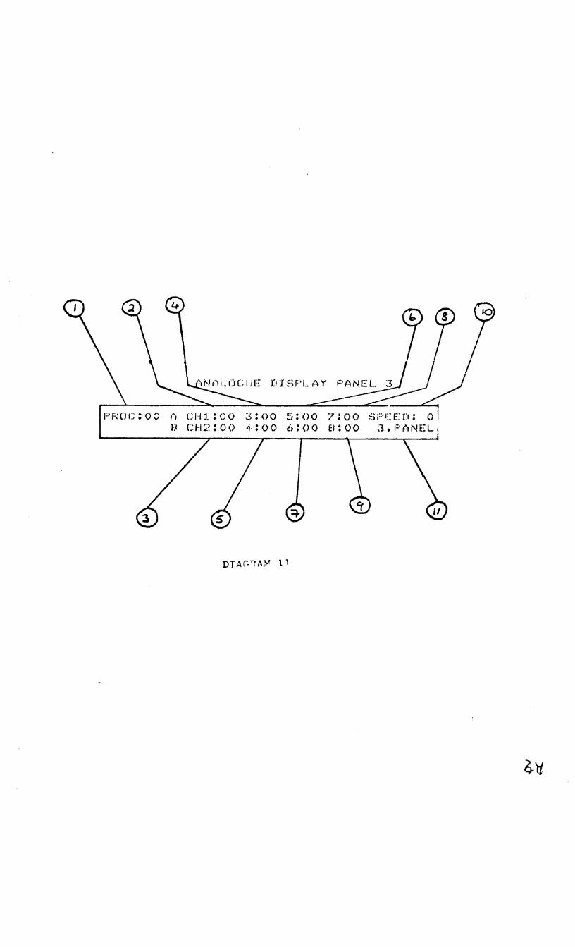
PROC:oo A CHl.:oo 3;00 ~;:oo 7:()0 SPCED: 0 B CH2:00 4:00 6:00 8:00 3.PANEL
3.6.ANALOGUE DISPLAY PANEL 3 (see dias 11)
3.6.1 PROG lndicaLes Pros number.
3.6.2 - 3.6.9 SEQUENCER OUTPUT VALUES 64 sLeps,
3.6.10 SPEED lndicaLes seauencer clocK speed 64 steps.
3.6.11 Indicates Lhird Panel in use.

P 1::: D G : () 0 ::> E G i'i : rJ 0 L DU PS : 0 0 1:;: E C M ! () T I M C DR : 0 RUN:o CH 1:0 2:0 3:0 410 s:o 6:0 7:0 a:o
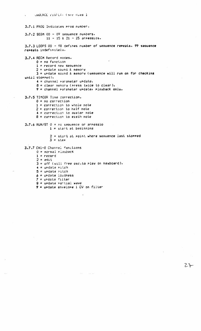
3.7.1 PROG IndicaLes Pros number.
3,7.2 SEQM 00 - 09 seauence numbers. 11 - 15 ~ Zl - 25 arpess1os.
3.7. 3 LOOPS 00 - 98 defines nu111ber of seauence rePeat.s. 99 seauence repeats indefin1te1~.
3.7.4 RECH Record modes, 0 = no function 1 = record new seauence 2 = UPdale sound & memor !:I 3 = UPdale sound & 11emory ( seauence will run on for
unt.i l SlOPPed). 4 = channel Parameter uPdate. 8 =clear memory (Press twice lo clear). 9 = channel Parameter updater Plawback onlv.
3.7. s TIMCOR Time correct.ion. 0 = no correction 1 = correct.1on lo whale note 2 = correc ilon to half note 4 = correct.ion lo Gu at.er note 8 = correction to eut.h note
3.7.6 RUN/ST 0 = no seauence or arF-essio 1 = sLart. al besinnins
check ins
2 = st.art. al Point. where seGuence last. st.oPPed 3 = sleP
3.7,7 CH1-8 Channel fund.ions 0 = normal Pl a1;:1bacl< 1 = record 2 = edit. 3 = off < wi 11 free osc.t.o Pla!:I on Ke~board). 4 = uPdate Pilch 5 = uPdaie PllCh 6 = ui=-da Le loudness 7 = uPdat.e fi l t.er a = UPdale Parlial wave 9 = u?dat.e enveloF-e 1 CV on filter

~· , CTll!r ,,,·lff\TE, lRMiSrER b. STORl1GE OF H<OGRAl1Mt.:S
4.1 To selecl or change any value on lhe disPlaY lhe cursor ~usl be at lhe pos1l1on of lhe value to be chansed.
4.2 The programme nu~ber is shown on all disPla~s and a new Prosra~~e can be selected regardless of which disPlaY is in use.However , uPon seleclion Lhe ~a1n disPlaY will always appear.
4.3 AnY values chansed will nol affecL lhe ~eruory and the new sound will be lost as soon as a new Prosra•me is selecled unless it has firsL been slored.
4.4 To slore a sound, Place a 9 in daLa lransf., press pros., lhen enler lhe desired pros nu~ber.
4.5 IL should be remembered when uPdalins sounds lhat lhe chansed values will onlY affect lhe srouP selecled and indicaled bY the srouP LEDs.This facility allows for different sounds to be prosrammed for each srouP.
4.6 LiKewiser when adJusLins envelope 3 and the LFO controls ~ike sure the ~~cond Panel LED is on.
o •. u I A LJN •
Af<P£GGIOS
5.1 The WAVE 2 will slore one orPe9s10 which can be allered in various ways by enLer1ns nuffiber codes in lhe SEQM coluffin on Lhe seouence disPlaY•
5.2 To enler an arPeSsio Pul Lhe desired nu~ber code in Lhe SEOM column and YOU will hear Lhe lasL sLored arpeggio. PlaY the new chord in arpessio form remembering Lo Keep all Lhe noLes dePressed.
· 5.3 Differenl arpessio modes can be selected while Lhe arPeSSio is running.
s.• ArPeSSio sPeed is conlrolled bY Lhe seauencer clock raLe on t.he third Panel.
5,5 Different. Parts of Lhe arPeSSio can be heard b~ ent.erinS values of bet.ween 1 & 16 in t.he looPs colu~n du~ins Playback.
l .
I SEQUENCER
6.1 To erase all previous!~ recorded seauences and clear seauence memory, enLer 8 in RECM column.The disPlaY will flash auesLion •arks and the clear command is conf1raed bY pressinS 8 again. This is a safety feaLure Lo safesuard asainst accidental erasure.
6,2 To record a new seauence use the followins Procedure:
1. in SEaM column enter seau nu1r1ber 2. in RECH colu~n enter 1 3. in TIHCOR column enter desired ti11e correction .... in CH! 1 en Ler 1 5. in RUN/ST enter 1
A timins note will now be heard. If reauired adJust this Lo a metronome beat with.envelope 2r and change the tempo w1Lh Lhe seauencer clock rate.
The seauencer will not start recording until Lhe first nole is Played. To sssisL with li~ins for future lines' the first four notes Played on Lhis first line are intro notes only. TheY w1ll be heard when record1ns subseauent lines but noL on PlaYbacK.
6. Play in Lhe first line and Press Lhe run sLOP button Lo end. 7. this line 1T1aY now be heard b':i enLerins a 1 in Lhe run/st. colu111n a. lo enter Lne next. line Place a l in channel 2 and Lhen a 1 in run/sL. The four iniro be~ts will be heard then I.he seauence will start.It will st.op aulomalicallw al Lhe end.
6.3 NOTES
6.3.1 All co~mands io Lhe seouencer must be made before runnins it. Com~ands cannot be entered while iL is runnins.
6.3.2 The Lime correction facililw can be set Lo different. values for each line.
6.3.3 To erase all or ParL of a se~uence line enter a 2 in lhe relevant. channel and run iL. Press Lhe run/st. button for the ParL of the line Lo be erased.
6.3.4 Ii is Possible al anw Lime, even while iL is runnins, Lo select a new Pro!ra~rue or ~odifw the sound in anw waw.
6.3.5 Anw oscillators not used in recordinS can st.ill be used with the Kewboard.e.s.iL is Possible Lo use 6 oscillators in recordins and PlaY alons with the seauence us1ns the lwo remainins oscillators.
6.3.6 If a sPlii ~01nl is entered, Lhe KeYboard Lo Lhe left of Lhis Point can be used Lo control the Pilch of the seauence.

PPG WAVE 2,0 Llaveforms
WAVEH\BLE pp, RT IA L lJA VE SHA PE lJavet. Partial w. Shape a o sine 28 0 I\'° left saw 0 1 0 I\/\ 28 1 A 1 0 /'v" 28 2 ,A 1 15~-:>N 28 12~ 2 o sine 28 18~ 3 59 11... 28 34 5 7,22,26 .N 29 - o rt. pw50%-
5 27 '.39 29 221L 99% 6 o sine 6 29 ~
p.wave
6 35 60 - triangle 8 0 ;1 61 - pulse wave 8 ~o A 62 - rectangular 8 63 - sawtooth 9 o sine 9 14 r1\ 9 1 5 ,.., 9 1 7 M 9 1 9 rV1 9 2 3 tVll"I 1 0 0 ;J\ 1 0 20 -'It 1 1 0 M.Jv 11 35 f\'V\, : 3 55 IL 1 3 56 sine 'to '
1 3 57 vV1 4 3 5 8 .fl.11 '13 59 saw 1 3 60 ./\ 14 1 4 2 -1 4 p-14 6 .......... 15 0 J;if:j\J-1 5 36 afup up 1 6 43 l;1:t/1 1 6 54 1 8 33 r:t 1 9 0 ;.,., 1 9 3 0 r'I
,.- 20 o sine 61 20 9-12 r'l 20 18~ 20 4oA~ J\. 21 O sine 21 8 V"-. 21 18 ~ 21 1 9 22 O sine 22 1 5 sine 6i 22 1~~ 22 23 0 \L\ 24 o7V 24 35 /}Ii 1 act up 26 0 (\ 26 1 4,-'\ 26 21 r'\ 26 7 r-A. 6' 27 O sine act up 27 'T r1V 27 6T sine
-"""" \t--lj;-:..::..!...-..:..:._~..:..!.-.:W....:U--~~~~~~~~--~--~~~~~~~~---1~
;>~ ~rJ1:~r:i ".:3. :3" 3 3: r--H ~ -0 w ~U.Q(.)Q ~ 'J~o G --. - -- ~'SS ~~~ ~-ll 11 !( I\ 11 11 11
..4-d __.. -£. __!,..-!. --.!.. II I f (/ ,, - ~
~~ V~<:s"'""'"""""' <:'" ~
;·~· ::::s; ~- :!.1' .;· ';.j' - .. """' ~ ----f ~ .. .,. :, .
/\A""X r- .,., ~ () Q CJ
( I ~,~ ~ "-..1 }( )( - \JI 0J
" ~ ....... -. -I ..:::+· ;·
Q~ Q;a~
e \!' @L--
~ <f<>®~
~~
(j-TI ~0

~~
(4 .. ~ ~n
I \ I \ I t ~ \ 11· -.~.:~, \\
'---·· ,, ··1
. 1
~ E c+·
~ ·ur.-. {ii[jj&~fil